EP3096049A1 - Rotating mechanism, machine tool, and semiconductor production device - Google Patents
Rotating mechanism, machine tool, and semiconductor production device Download PDFInfo
- Publication number
- EP3096049A1 EP3096049A1 EP14878718.7A EP14878718A EP3096049A1 EP 3096049 A1 EP3096049 A1 EP 3096049A1 EP 14878718 A EP14878718 A EP 14878718A EP 3096049 A1 EP3096049 A1 EP 3096049A1
- Authority
- EP
- European Patent Office
- Prior art keywords
- housing
- rotation mechanism
- groove
- rotary member
- gap
- Prior art date
- Legal status (The legal status is an assumption and is not a legal conclusion. Google has not performed a legal analysis and makes no representation as to the accuracy of the status listed.)
- Withdrawn
Links
Images





Classifications
-
- F—MECHANICAL ENGINEERING; LIGHTING; HEATING; WEAPONS; BLASTING
- F16—ENGINEERING ELEMENTS AND UNITS; GENERAL MEASURES FOR PRODUCING AND MAINTAINING EFFECTIVE FUNCTIONING OF MACHINES OR INSTALLATIONS; THERMAL INSULATION IN GENERAL
- F16C—SHAFTS; FLEXIBLE SHAFTS; ELEMENTS OR CRANKSHAFT MECHANISMS; ROTARY BODIES OTHER THAN GEARING ELEMENTS; BEARINGS
- F16C39/00—Relieving load on bearings
- F16C39/04—Relieving load on bearings using hydraulic or pneumatic means
-
- F—MECHANICAL ENGINEERING; LIGHTING; HEATING; WEAPONS; BLASTING
- F16—ENGINEERING ELEMENTS AND UNITS; GENERAL MEASURES FOR PRODUCING AND MAINTAINING EFFECTIVE FUNCTIONING OF MACHINES OR INSTALLATIONS; THERMAL INSULATION IN GENERAL
- F16C—SHAFTS; FLEXIBLE SHAFTS; ELEMENTS OR CRANKSHAFT MECHANISMS; ROTARY BODIES OTHER THAN GEARING ELEMENTS; BEARINGS
- F16C41/00—Other accessories, e.g. devices integrated in the bearing not relating to the bearing function as such
- F16C41/005—Fluid passages not relating to lubrication or cooling
-
- B—PERFORMING OPERATIONS; TRANSPORTING
- B23—MACHINE TOOLS; METAL-WORKING NOT OTHERWISE PROVIDED FOR
- B23Q—DETAILS, COMPONENTS, OR ACCESSORIES FOR MACHINE TOOLS, e.g. ARRANGEMENTS FOR COPYING OR CONTROLLING; MACHINE TOOLS IN GENERAL CHARACTERISED BY THE CONSTRUCTION OF PARTICULAR DETAILS OR COMPONENTS; COMBINATIONS OR ASSOCIATIONS OF METAL-WORKING MACHINES, NOT DIRECTED TO A PARTICULAR RESULT
- B23Q1/00—Members which are comprised in the general build-up of a form of machine, particularly relatively large fixed members
- B23Q1/70—Stationary or movable members for carrying working-spindles for attachment of tools or work
-
- B—PERFORMING OPERATIONS; TRANSPORTING
- B23—MACHINE TOOLS; METAL-WORKING NOT OTHERWISE PROVIDED FOR
- B23Q—DETAILS, COMPONENTS, OR ACCESSORIES FOR MACHINE TOOLS, e.g. ARRANGEMENTS FOR COPYING OR CONTROLLING; MACHINE TOOLS IN GENERAL CHARACTERISED BY THE CONSTRUCTION OF PARTICULAR DETAILS OR COMPONENTS; COMBINATIONS OR ASSOCIATIONS OF METAL-WORKING MACHINES, NOT DIRECTED TO A PARTICULAR RESULT
- B23Q11/00—Accessories fitted to machine tools for keeping tools or parts of the machine in good working condition or for cooling work; Safety devices specially combined with or arranged in, or specially adapted for use in connection with, machine tools
- B23Q11/0042—Devices for removing chips
- B23Q11/0046—Devices for removing chips by sucking
-
- B—PERFORMING OPERATIONS; TRANSPORTING
- B23—MACHINE TOOLS; METAL-WORKING NOT OTHERWISE PROVIDED FOR
- B23Q—DETAILS, COMPONENTS, OR ACCESSORIES FOR MACHINE TOOLS, e.g. ARRANGEMENTS FOR COPYING OR CONTROLLING; MACHINE TOOLS IN GENERAL CHARACTERISED BY THE CONSTRUCTION OF PARTICULAR DETAILS OR COMPONENTS; COMBINATIONS OR ASSOCIATIONS OF METAL-WORKING MACHINES, NOT DIRECTED TO A PARTICULAR RESULT
- B23Q11/00—Accessories fitted to machine tools for keeping tools or parts of the machine in good working condition or for cooling work; Safety devices specially combined with or arranged in, or specially adapted for use in connection with, machine tools
- B23Q11/08—Protective coverings for parts of machine tools; Splash guards
- B23Q11/0883—Protective coverings for parts of machine tools; Splash guards for spindles, e.g. for their bearings or casings
-
- F—MECHANICAL ENGINEERING; LIGHTING; HEATING; WEAPONS; BLASTING
- F16—ENGINEERING ELEMENTS AND UNITS; GENERAL MEASURES FOR PRODUCING AND MAINTAINING EFFECTIVE FUNCTIONING OF MACHINES OR INSTALLATIONS; THERMAL INSULATION IN GENERAL
- F16C—SHAFTS; FLEXIBLE SHAFTS; ELEMENTS OR CRANKSHAFT MECHANISMS; ROTARY BODIES OTHER THAN GEARING ELEMENTS; BEARINGS
- F16C17/00—Sliding-contact bearings for exclusively rotary movement
- F16C17/04—Sliding-contact bearings for exclusively rotary movement for axial load only
- F16C17/08—Sliding-contact bearings for exclusively rotary movement for axial load only for supporting the end face of a shaft or other member, e.g. footstep bearings
-
- F—MECHANICAL ENGINEERING; LIGHTING; HEATING; WEAPONS; BLASTING
- F16—ENGINEERING ELEMENTS AND UNITS; GENERAL MEASURES FOR PRODUCING AND MAINTAINING EFFECTIVE FUNCTIONING OF MACHINES OR INSTALLATIONS; THERMAL INSULATION IN GENERAL
- F16C—SHAFTS; FLEXIBLE SHAFTS; ELEMENTS OR CRANKSHAFT MECHANISMS; ROTARY BODIES OTHER THAN GEARING ELEMENTS; BEARINGS
- F16C19/00—Bearings with rolling contact, for exclusively rotary movement
- F16C19/54—Systems consisting of a plurality of bearings with rolling friction
- F16C19/541—Systems consisting of juxtaposed rolling bearings including at least one angular contact bearing
- F16C19/542—Systems consisting of juxtaposed rolling bearings including at least one angular contact bearing with two rolling bearings with angular contact
- F16C19/543—Systems consisting of juxtaposed rolling bearings including at least one angular contact bearing with two rolling bearings with angular contact in O-arrangement
-
- F—MECHANICAL ENGINEERING; LIGHTING; HEATING; WEAPONS; BLASTING
- F16—ENGINEERING ELEMENTS AND UNITS; GENERAL MEASURES FOR PRODUCING AND MAINTAINING EFFECTIVE FUNCTIONING OF MACHINES OR INSTALLATIONS; THERMAL INSULATION IN GENERAL
- F16C—SHAFTS; FLEXIBLE SHAFTS; ELEMENTS OR CRANKSHAFT MECHANISMS; ROTARY BODIES OTHER THAN GEARING ELEMENTS; BEARINGS
- F16C21/00—Combinations of sliding-contact bearings with ball or roller bearings, for exclusively rotary movement
-
- F—MECHANICAL ENGINEERING; LIGHTING; HEATING; WEAPONS; BLASTING
- F16—ENGINEERING ELEMENTS AND UNITS; GENERAL MEASURES FOR PRODUCING AND MAINTAINING EFFECTIVE FUNCTIONING OF MACHINES OR INSTALLATIONS; THERMAL INSULATION IN GENERAL
- F16C—SHAFTS; FLEXIBLE SHAFTS; ELEMENTS OR CRANKSHAFT MECHANISMS; ROTARY BODIES OTHER THAN GEARING ELEMENTS; BEARINGS
- F16C32/00—Bearings not otherwise provided for
- F16C32/06—Bearings not otherwise provided for with moving member supported by a fluid cushion formed, at least to a large extent, otherwise than by movement of the shaft, e.g. hydrostatic air-cushion bearings
- F16C32/0603—Bearings not otherwise provided for with moving member supported by a fluid cushion formed, at least to a large extent, otherwise than by movement of the shaft, e.g. hydrostatic air-cushion bearings supported by a gas cushion, e.g. an air cushion
- F16C32/0614—Bearings not otherwise provided for with moving member supported by a fluid cushion formed, at least to a large extent, otherwise than by movement of the shaft, e.g. hydrostatic air-cushion bearings supported by a gas cushion, e.g. an air cushion the gas being supplied under pressure, e.g. aerostatic bearings
-
- F—MECHANICAL ENGINEERING; LIGHTING; HEATING; WEAPONS; BLASTING
- F16—ENGINEERING ELEMENTS AND UNITS; GENERAL MEASURES FOR PRODUCING AND MAINTAINING EFFECTIVE FUNCTIONING OF MACHINES OR INSTALLATIONS; THERMAL INSULATION IN GENERAL
- F16C—SHAFTS; FLEXIBLE SHAFTS; ELEMENTS OR CRANKSHAFT MECHANISMS; ROTARY BODIES OTHER THAN GEARING ELEMENTS; BEARINGS
- F16C32/00—Bearings not otherwise provided for
- F16C32/06—Bearings not otherwise provided for with moving member supported by a fluid cushion formed, at least to a large extent, otherwise than by movement of the shaft, e.g. hydrostatic air-cushion bearings
- F16C32/0603—Bearings not otherwise provided for with moving member supported by a fluid cushion formed, at least to a large extent, otherwise than by movement of the shaft, e.g. hydrostatic air-cushion bearings supported by a gas cushion, e.g. an air cushion
- F16C32/0614—Bearings not otherwise provided for with moving member supported by a fluid cushion formed, at least to a large extent, otherwise than by movement of the shaft, e.g. hydrostatic air-cushion bearings supported by a gas cushion, e.g. an air cushion the gas being supplied under pressure, e.g. aerostatic bearings
- F16C32/0622—Bearings not otherwise provided for with moving member supported by a fluid cushion formed, at least to a large extent, otherwise than by movement of the shaft, e.g. hydrostatic air-cushion bearings supported by a gas cushion, e.g. an air cushion the gas being supplied under pressure, e.g. aerostatic bearings via nozzles, restrictors
-
- F—MECHANICAL ENGINEERING; LIGHTING; HEATING; WEAPONS; BLASTING
- F16—ENGINEERING ELEMENTS AND UNITS; GENERAL MEASURES FOR PRODUCING AND MAINTAINING EFFECTIVE FUNCTIONING OF MACHINES OR INSTALLATIONS; THERMAL INSULATION IN GENERAL
- F16C—SHAFTS; FLEXIBLE SHAFTS; ELEMENTS OR CRANKSHAFT MECHANISMS; ROTARY BODIES OTHER THAN GEARING ELEMENTS; BEARINGS
- F16C32/00—Bearings not otherwise provided for
- F16C32/06—Bearings not otherwise provided for with moving member supported by a fluid cushion formed, at least to a large extent, otherwise than by movement of the shaft, e.g. hydrostatic air-cushion bearings
- F16C32/0681—Construction or mounting aspects of hydrostatic bearings, for exclusively rotary movement, related to the direction of load
- F16C32/0692—Construction or mounting aspects of hydrostatic bearings, for exclusively rotary movement, related to the direction of load for axial load only
-
- F—MECHANICAL ENGINEERING; LIGHTING; HEATING; WEAPONS; BLASTING
- F16—ENGINEERING ELEMENTS AND UNITS; GENERAL MEASURES FOR PRODUCING AND MAINTAINING EFFECTIVE FUNCTIONING OF MACHINES OR INSTALLATIONS; THERMAL INSULATION IN GENERAL
- F16J—PISTONS; CYLINDERS; SEALINGS
- F16J15/00—Sealings
- F16J15/16—Sealings between relatively-moving surfaces
- F16J15/40—Sealings between relatively-moving surfaces by means of fluid
-
- H—ELECTRICITY
- H02—GENERATION; CONVERSION OR DISTRIBUTION OF ELECTRIC POWER
- H02K—DYNAMO-ELECTRIC MACHINES
- H02K5/00—Casings; Enclosures; Supports
- H02K5/04—Casings or enclosures characterised by the shape, form or construction thereof
- H02K5/12—Casings or enclosures characterised by the shape, form or construction thereof specially adapted for operating in liquid or gas
- H02K5/124—Sealing of shafts
-
- H—ELECTRICITY
- H02—GENERATION; CONVERSION OR DISTRIBUTION OF ELECTRIC POWER
- H02K—DYNAMO-ELECTRIC MACHINES
- H02K5/00—Casings; Enclosures; Supports
- H02K5/04—Casings or enclosures characterised by the shape, form or construction thereof
- H02K5/16—Means for supporting bearings, e.g. insulating supports or means for fitting bearings in the bearing-shields
-
- H—ELECTRICITY
- H02—GENERATION; CONVERSION OR DISTRIBUTION OF ELECTRIC POWER
- H02K—DYNAMO-ELECTRIC MACHINES
- H02K5/00—Casings; Enclosures; Supports
- H02K5/04—Casings or enclosures characterised by the shape, form or construction thereof
- H02K5/16—Means for supporting bearings, e.g. insulating supports or means for fitting bearings in the bearing-shields
- H02K5/173—Means for supporting bearings, e.g. insulating supports or means for fitting bearings in the bearing-shields using bearings with rolling contact, e.g. ball bearings
- H02K5/1735—Means for supporting bearings, e.g. insulating supports or means for fitting bearings in the bearing-shields using bearings with rolling contact, e.g. ball bearings radially supporting the rotary shaft at only one end of the rotor
-
- H—ELECTRICITY
- H02—GENERATION; CONVERSION OR DISTRIBUTION OF ELECTRIC POWER
- H02K—DYNAMO-ELECTRIC MACHINES
- H02K9/00—Arrangements for cooling or ventilating
- H02K9/02—Arrangements for cooling or ventilating by ambient air flowing through the machine
- H02K9/04—Arrangements for cooling or ventilating by ambient air flowing through the machine having means for generating a flow of cooling medium
-
- H—ELECTRICITY
- H02—GENERATION; CONVERSION OR DISTRIBUTION OF ELECTRIC POWER
- H02K—DYNAMO-ELECTRIC MACHINES
- H02K9/00—Arrangements for cooling or ventilating
- H02K9/14—Arrangements for cooling or ventilating wherein gaseous cooling medium circulates between the machine casing and a surrounding mantle
-
- H—ELECTRICITY
- H10—SEMICONDUCTOR DEVICES; ELECTRIC SOLID-STATE DEVICES NOT OTHERWISE PROVIDED FOR
- H10P—GENERIC PROCESSES OR APPARATUS FOR THE MANUFACTURE OR TREATMENT OF DEVICES COVERED BY CLASS H10
- H10P72/00—Handling or holding of wafers, substrates or devices during manufacture or treatment thereof
- H10P72/70—Handling or holding of wafers, substrates or devices during manufacture or treatment thereof for supporting or gripping
- H10P72/76—Handling or holding of wafers, substrates or devices during manufacture or treatment thereof for supporting or gripping using mechanical means, e.g. clamps or pinches
- H10P72/7604—Handling or holding of wafers, substrates or devices during manufacture or treatment thereof for supporting or gripping using mechanical means, e.g. clamps or pinches the wafers being placed on a susceptor, stage or support
- H10P72/7626—Handling or holding of wafers, substrates or devices during manufacture or treatment thereof for supporting or gripping using mechanical means, e.g. clamps or pinches the wafers being placed on a susceptor, stage or support characterised by the construction of the shaft
-
- H—ELECTRICITY
- H10—SEMICONDUCTOR DEVICES; ELECTRIC SOLID-STATE DEVICES NOT OTHERWISE PROVIDED FOR
- H10P—GENERIC PROCESSES OR APPARATUS FOR THE MANUFACTURE OR TREATMENT OF DEVICES COVERED BY CLASS H10
- H10P72/00—Handling or holding of wafers, substrates or devices during manufacture or treatment thereof
- H10P72/70—Handling or holding of wafers, substrates or devices during manufacture or treatment thereof for supporting or gripping
- H10P72/78—Handling or holding of wafers, substrates or devices during manufacture or treatment thereof for supporting or gripping using vacuum or suction, e.g. Bernoulli chucks
-
- F—MECHANICAL ENGINEERING; LIGHTING; HEATING; WEAPONS; BLASTING
- F16—ENGINEERING ELEMENTS AND UNITS; GENERAL MEASURES FOR PRODUCING AND MAINTAINING EFFECTIVE FUNCTIONING OF MACHINES OR INSTALLATIONS; THERMAL INSULATION IN GENERAL
- F16C—SHAFTS; FLEXIBLE SHAFTS; ELEMENTS OR CRANKSHAFT MECHANISMS; ROTARY BODIES OTHER THAN GEARING ELEMENTS; BEARINGS
- F16C2235/00—Cleaning
-
- F—MECHANICAL ENGINEERING; LIGHTING; HEATING; WEAPONS; BLASTING
- F16—ENGINEERING ELEMENTS AND UNITS; GENERAL MEASURES FOR PRODUCING AND MAINTAINING EFFECTIVE FUNCTIONING OF MACHINES OR INSTALLATIONS; THERMAL INSULATION IN GENERAL
- F16C—SHAFTS; FLEXIBLE SHAFTS; ELEMENTS OR CRANKSHAFT MECHANISMS; ROTARY BODIES OTHER THAN GEARING ELEMENTS; BEARINGS
- F16C2300/00—Application independent of particular apparatuses
- F16C2300/20—Application independent of particular apparatuses related to type of movement
- F16C2300/22—High-speed rotation
-
- F—MECHANICAL ENGINEERING; LIGHTING; HEATING; WEAPONS; BLASTING
- F16—ENGINEERING ELEMENTS AND UNITS; GENERAL MEASURES FOR PRODUCING AND MAINTAINING EFFECTIVE FUNCTIONING OF MACHINES OR INSTALLATIONS; THERMAL INSULATION IN GENERAL
- F16C—SHAFTS; FLEXIBLE SHAFTS; ELEMENTS OR CRANKSHAFT MECHANISMS; ROTARY BODIES OTHER THAN GEARING ELEMENTS; BEARINGS
- F16C2322/00—Apparatus used in shaping articles
- F16C2322/39—General buildup of machine tools, e.g. spindles, slides, actuators
-
- F—MECHANICAL ENGINEERING; LIGHTING; HEATING; WEAPONS; BLASTING
- F16—ENGINEERING ELEMENTS AND UNITS; GENERAL MEASURES FOR PRODUCING AND MAINTAINING EFFECTIVE FUNCTIONING OF MACHINES OR INSTALLATIONS; THERMAL INSULATION IN GENERAL
- F16C—SHAFTS; FLEXIBLE SHAFTS; ELEMENTS OR CRANKSHAFT MECHANISMS; ROTARY BODIES OTHER THAN GEARING ELEMENTS; BEARINGS
- F16C2380/00—Electrical apparatus
- F16C2380/18—Handling tools for semiconductor devices
Definitions
- the present invention relates to a rotation mechanism, a machine tool, and a semiconductor manufacturing device.
- a rotation mechanism that rotates a rotary stage or rotates a tool or a workpiece is used.
- a rotation mechanism for example, a spindle with static pressure gas bearing is disclosed in Patent Literature 1.
- a chuck sleeve and a bearing sleeve are vertically fitted into a sleeve fitting hole of a housing, and an exhaust space formed between both of the sleeves is made to communicate with the outside through an exhaust passage provided at the housing.
- a table for supporting a workpiece is fitted to an upper end of a main spindle.
- the chuck sleeve is provided with a suction passage in communication with a workpiece adsorption recessed portion formed at the table. Compressed gas supplied into a radial bearing gap between the main spindle and the bearing sleeve is exhausted to the outside from the exhaust space and the exhaust passage.
- Patent Literature 1 Japanese Laid-open Patent Publication No. 7-217655
- Patent Literature 1 in the case where compressed gas flows into a gap between a chuck sleeve and a main spindle, the compressed gas is prevented from flowing out over the housing by sucking the compressed gas into a suction passage formed at the chuck sleeve, thereby preventing dust contained in the compressed gas supporting the main spindle from adhering to a surface of a workpiece placed on a table.
- a foreign matter may enter between the main spindle and the chuck sleeve from the outside of the main spindle, and may affect supporting of the main spindle.
- the present invention is directed to suppressing entrance of a foreign matter from the outside of a shaft included in a rotation mechanism.
- a rotation mechanism comprising: a housing; a shaft inserted through a hole provided at the housing; a bearing installed at the housing and configured to rotatably support the shaft; a rotary member provided at one end portion of the shaft, configured to be rotated together with the shaft, and having a portion that projects to a radially outer side of the hole and faces the housing with a gap having a predetermined size; and a gas passage configured to connect the gap to outside of the housing and allow gas contained in a portion of the gap to pass to the outside of the housing.
- the portion of the rotary member that projects to radially outer side of the hole into which the shaft is inserted faces the housing with the gap having the predetermined size, and allows the gas contained in the portion of the gap to pass to the outside of the housing from the gas passage.
- the rotation mechanism exhausts the gas contained in the gap from a more outer side of the rotation mechanism than a portion between the hole and shaft. Therefore, entrance of a foreign matter from the outside of the shaft can be suppressed.
- the bearing is a rolling bearing including an outer ring, an inner ring disposed on a radially inner side of the outer ring, and a rolling element disposed between the outer ring and the inner ring, and a space surrounded by the hole and the shaft is opened on the rotary member side and between the outer ring and the inner ring.
- the gas contained inside the housing is exhausted to the outside of the housing, passing through between the outer ring and the inner ring of the bearing, the space, gap, and the gas passage.
- the space surrounded by the hole and shaft can exhaust heat generated at the bearing to the outside of the housing, temperature increase at the bearing can be suppressed.
- the housing includes, inside, an electric motor having a rotor connected to the other end portion of the shaft, and cooling gas is supplied to the electric motor.
- an electric motor having a rotor connected to the other end portion of the shaft, and cooling gas is supplied to the electric motor.
- a groove extending in a circumferential direction of the hole is provided in at least one of a portion located in the housing and facing the rotary member and a portion located in the rotary member and facing the housing, and the gas passage connects the gap to the outside of the housing at a position of the groove. Since the groove is provided around the hole, the gas contained in the gap is exhausted to the outside of the housing from the entire groove. Due to this operation, entrance of a foreign matter and outflow of the dust contained inside the housing can be effectively suppressed in the rotation mechanism.
- the groove is provided at a portion located in the housing and facing the rotary member, and the gas passage is provided in the housing and opened to the groove. Consequently, entrance of a foreign matter and outflow of the dust contained inside the housing can be effectively suppressed.
- a plurality of the grooves is provided in a radial direction of the hole.
- the rotation mechanism includes the plurality of grooves in the radial direction of the housing, thereby improving sealing function. Moreover, the rotation mechanism can effectively suppress entrance of a foreign matter from the outside of the shaft by the plurality of grooves. Furthermore, when the gap between the rotary member and the housing is cleaned with liquid such as cleaning liquid, the cleaning liquid can be supplied from the grooves on outer side, and the cleaning liquid can be collected from the grooves on the outer side and an inner side of the housing. With this structure, the rotation mechanism can suppress entrance of the cleaning liquid into the bearing.
- the groove is provided at a portion located in the rotary member and facing the housing, and the gas passage is provided in the housing and opened to a position located in the housing and facing the groove.
- a plurality of the grooves is provided in a radial direction of the hole.
- the rotation mechanism includes the plurality of grooves in the radial direction of the housing, thereby improving sealing function. Moreover, the rotation mechanism can effectively suppress entrance of a foreign matter from the outside of the shaft by the plurality of grooves. Furthermore, when the gap between the rotary member and the housing is cleaned with liquid such as cleaning liquid, the cleaning liquid can be supplied from the grooves on outer side, and the cleaning liquid can be collected from the grooves on the outer side and an inner side of the housing. With this structure, the rotation mechanism can suppress entrance of the cleaning liquid to the bearing.
- a through-hole penetrating the rotary member in a thickness direction is provided, and gas is exhausted from the rotary member on an opposite side of the housing through the through-hole, the gap, and the gas passage.
- an adsorption mechanism such as a vacuum chuck can be provided at the rotary member by utilizing the gas passage.
- the housing includes other gas passage different from the gas passage, and the other gas passage different from the gas passage allows gas contained in a portion of the gap to pass to the outside of the housing.
- the rotation mechanism sucks, from the gas passage, the gas from a suction mechanism and can exhaust the gas contained in the gap from the gas passage to the outside of the housing. Since the gas contained in the gap is exhausted also from the other gas passage, an exhausting amount of the gas from the gap is reduced in the gas passage for the adsorption mechanism. As a result, a flow rate at an exhaust system of the adsorption mechanism can be reduced. Furthermore, since pressure loss at the exhaust system of the adsorption mechanism is reduced, chuck pressure can be increased.
- the housing includes a passage to suck gas from between the housing and the shaft. Entrance of the cleaning liquid on the bearing side can be suppressed by sucking the gas from between the housing and the shaft while the gap is cleaned with the cleaning liquid.
- the rotation mechanism includes a supply passage configured to connect the gap to the outside of the housing and supply gas to a portion of the gap from a portion located on a more radially outer side of the hole than the gas passage.
- the rotation mechanism can suppress entrance of a foreign matter such as liquid from the outside of the housing into the radially inner side of the gap by the gas supplied to the gap from the supply passage.
- the rotation mechanism can suppress high-pressure gas supplied from the supply passage from flowing into the inside of the housing.
- the rotation mechanism includes a first groove provided at least at one of a portion located in the housing and facing the rotary member and a portion located in the rotary member and facing the housing, and extending in a circumferential direction of the hole; and a second groove provided at least at one of a portion located in the housing and facing the rotary member and a portion located in the rotary member and facing the housing, and disposed on a more radially outer side of the hole than the first groove, and extending in a circumferential direction of the hole, wherein the gas passage connects the gap to the outside of the housing at a position of the first groove, and the supply passage connects the gap to the outside of the housing at a portion of the second groove.
- the rotation mechanism can efficiently fill the high-pressure gas to the gap across a rotary member and an entire peripheral area of the housing, and also can efficiently exhaust the gas from the gap, by using the first groove and the second groove.
- the rotation mechanism includes a third groove provided at least at one of a portion located in the housing and facing the rotary member and a portion located in the rotary member and facing the housing, and also the third groove being positioned between the first groove and the second groove, extending in a circumferential direction of the hole, and being connected to the outside of the housing.
- the high-pressure gas flowing out to the gap from the supply passage is collected in the third groove and can be emitted to the outside of the housing. Therefore, a flow rate of the high-pressure gas supplied from the supply passage to flow in the gas passage can be reduced.
- the rotation mechanism includes, in the housing, an opening portion opened on a more radially outer side of the hole than the gas passage, facing the rotary member, and extending in a circumferential direction of the hole, wherein the supply passage is connected to the opening portion.
- the high-pressure gas supplied from the supply passage through the opening portion is exhausted to the radially outer side of the housing. Therefore, a flow rate of the high-pressure gas flowing in the exhaust passage can be reduced after supplied from the supply passage.
- a machine tool according to the present invention includes the above-described rotation mechanism. Therefore, entrance of a foreign matter from outside of a shaft included in the machine tool can be suppressed.
- a semiconductor manufacturing device includes the above-described rotation mechanism. Therefore, entrance of a foreign matter from outside of a shaft included in the semiconductor manufacturing device can be suppressed.
- the present invention can suppress entrance of a foreign matter from the outside of the shaft included in the rotation mechanism.
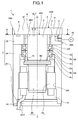
- FIG. 1 is a cross-sectional view illustrating a rotation mechanism according to a first embodiment.
- FIG. 1 shows a cross-section illustrating a rotation mechanism 1 taken along a plane including a rotational center axis Zr of the rotation mechanism 1 and parallel to the rotational center axis Zr.
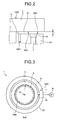
- FIG. 2 is an enlarged view illustrating a gap in the rotation mechanism according to the first embodiment.
- FIG. 3 is a view taken along an arrow A - A in FIG. 1 .
- the rotation mechanism 1 is a machine element that transmits rotation, and is applied to, for example, in a machine tool, a conveyance device used under a special environment such as a vacuum chamber, a semiconductor manufacturing device, a flat panel display manufacturing device, or the like.
- a description will be given for a case where the rotation mechanism 1 is a spindle unit including a spindle as a rotary shaft, but an object to which the rotation mechanism 1 is applied is not limited thereto.
- the rotation mechanism 1 includes a housing 2, a shaft 4, bearings 6A, 6B, a rotary member 5, and a gas passage 7.
- the housing 2 is a member to house the bearings 6A, 6B.
- the housing 2 includes a side portion 2A having a cylindrical shape, a first member 2B provided at one end portion of the side portion 2A, and a second member 2C provided at the other end portion of the side portion 2A.
- the side portion 2A, first member 2B, and second member 2C constitute part of the housing 2.
- the side portion 2A is a cylindrical member, and includes a through-hole 2I that runs from one end portion to the other end portion, more specifically, from the first member 2B to the second member 2C.
- Both of the first member 2B and the second member 2C are plate-like members.
- the first member 2B and the second member 2C each have a circle shape in a planar view, but the shape is not limited thereto.
- the first member 2B includes the rotational center axis Zr of the shaft 4, and also includes a hole 2BH penetrating in a thickness direction.
- the second member 2C includes a through-hole 2CH.
- a power supply cable 3C is inserted through the through-hole 2CH.
- the power supply cable 3C supplies power to an electric motor 3 provided inside the housing 2, more specifically, at a portion surrounded by the side portion 2A, first member 2B, and second member 2C.
- the shaft 4 is an output shaft of the rotation mechanism 1 and passes through the first member 2B by being inserted into the housing 2, more specifically, the hole 2BH provided at the first member 2B of the housing 2.
- the bearings 6A, 6B are installed at the housing 2, in the present embodiment, inside of the housing 2, and adapted to rotatably support the shaft 4.
- the shaft 4 is supported at the housing 2 by the two bearings 6A, 6B, but the number of the bearings is not limited to two.
- the bearings 6A, 6B each include an outer ring 6a, a rolling element 6b, and an inner ring 6c.
- the inner ring 6c is arranged on a radially inner side of the outer ring 6a.
- both of the bearings 6A, 6B are rolling bearings.
- the rolling element 6b is disposed between the outer ring 6a and the inner ring 6c.
- the bearings 6A, 6B each have the outer ring 6a contacting an inner wall 2W of the through-hole 2I included in the side portion 2A of the housing 2. With this structure, the bearings 6A, 6B are attached to the housing 2.
- both of the bearings 6A, 6B are ball bearings, but the type of the bearings 6A, 6B as the rolling bearings is not limited to the ball bearing. Furthermore, in the present embodiment, both of the bearings 6A, 6B are the rolling bearings, but may also be slide bearings.
- the rotary member 5 is provided at one end portion 4TA of the shaft 4, and is rotated together with the shaft 4.
- the rotary member 5 has an object loaded on a surface 5SB located on an opposite side of the one end portion 4TA of the shaft 4.
- the rotary member 5 is a plate-like member and has a circle shape in a planar view.
- the rotary member 5 projects to a radially outer side of the hole 2BH provided at the first member 2B of the housing 2.
- a portion 5F that projects to the radially outer side of the hole 2BH (hereinafter, conveniently referred to as a flange portion) faces the housing 2 with a predetermined gap 10 as illustrated in FIG. 2 .
- the gap 10 is formed between a surface 2BS of the first member 2B included in the housing 2 and facing the rotary member 5 and a surface 5SA located at the rotary member 5 and facing the first member 2B.
- the gap 10 is a sealing portion to seal a space between the inside and the outside of the housing 2.
- the gap 10 illustrated in FIG. 2 has a size t from several ⁇ m to several tens of ⁇ m, for example.
- the gas passage 7 is provided at a portion located in the housing 2 and facing the rotary member 5, more specifically, the first member 2B of the housing 2.
- the gas passage 7 connects a surface 2BS located in the first member 2B and facing the rotary member 5 to a side portion 2BE linked to the surface 2BS, and the gas passage passes through the first member 2B.
- the gas passage 7 connects the gap 10 to the outside of the housing 2, and allows gas contained in the gap 10 portion to pass to the outside of the housing 2.
- an exhaust device 50 is connected to the gas passage 7.
- the exhaust device 50 sucks and exhausts the gas contained inside the gas passage 7 (in the present embodiment, air).
- the exhaust device 50 is, for example, a pump.
- a groove 8 is formed on the surface 2BS that is a portion of the first member 2B included in the housing 2 and faces the rotary member 5.
- the groove 8 extends in a circumferential direction of the hole 2BH included in the first member 2B as illustrated in FIG. 3 .
- the gas passage 7 is opened to the groove 8. More specifically, the gas passage 7 is opened to a bottom portion of the groove 8. In FIG. 3 , an opening portion 7H of the gas passage 7 is illustrated.
- the number of gas passage 7 included in the rotation mechanism 1 is one, but the number thereof is not limited thereto.
- the gas passages 7 are provided at equal intervals around the rotational center axis Zr. The gas contained in the gap 10 passes and is exhausted from the gas passage 7 to the outside of the housing 2, and exhausting balance of the gas is improved by disposing the plurality of gas passages 7 at equal intervals. Therefore, disposing the plurality of gas passages 7 at equal intervals is preferable.
- the electric motor 3 is provided inside the housing 2.
- the electric motor 3 includes a rotor 3R, and a stator 3S provided on a radially outer side of the rotor 3R.
- the stator 3S is attached to the inner wall 2W of the through-hole 2I included in the side portion 2A.
- the rotor 3R is connected to the other end portion of the shaft 4. With this structure, the rotor 3R, shaft 4 and rotary member 5 are integrally rotated around the rotational center axis Zr.
- a form of the electric motor 3 is not limited.
- the gas contained in the gap 10 is exhausted from the gas passage 7 to the outside of the housing 2, thereby suppressing entrance of a foreign matter into between the shaft 4 and the housing 2 from the outside of the rotation mechanism 1, entrance of a foreign matter into the bearings 6A, 6B, and outflow of dust from the inside of housing 2 to the outside of the rotation mechanism 1.
- the dust flowing out from the inside of the housing 2 may include dust from the bearings 6A, 6B and dust from the electric motor 3, for example.
- the rotation mechanism 1 does not necessarily include the groove 8, but since the groove 8 is provided around the hole 2BH, the gas contained in the gap 10 is exhausted from the entire groove 8 to the outside of the housing.
- a mechanical bearing such as a rolling bearing or a slide bearing, which does not require any gas supply can be used for the bearings 6A, 6B.
- sealing performance can be improved by making the size t of the gap 10 small.
- the size t of the gap 10 is determined while allowing predetermined tolerance relative to accuracy of the shaft 4 (deflection in a sealing surface direction), flatness and perpendicularity with respect to the shaft 4 of the sealing surface on the housing 2 side.
- the mentioned sealing surface is, on the housing 2 side, the surface 2BS of the first member 2B located on the rotary member 5 side, and also on the rotary member 5 side, is the surface 5SA of the rotary member 5 located on the first member 2B side.
- the inner ring 6c of the bearing 6A contacts an annular spacer 9 which is provided at shaft 4 on the rotary member 5 side.
- the rotary member 5 and the shaft 4 are fastened and fixed with a bolt BLT, for example, as illustrated in FIG. 1 .
- the spacer 9 is disposed between the bearing 6A and the rotary member 5.
- the outer ring 6a contacts the first member 2B of the housing 2.
- the inner ring 6c of the bearing 6A contacts the inner ring 6c of the bearing 6B, and also the annular spacer 4S contacts the inner ring 6c of the bearing 6B.
- a lock nut 4N is screwed into the shaft 4 from the spacer 4S side.
- the spacer 4S is disposed at the shaft 4 on the electric motor 3 side.
- the bearings 6A, 6B are fixed between the spacer 4S and the spacer 9 and furthermore between the lock nut 4N and the rotary member 5.
- the bearings 6A, 6B are attached to the inner wall 2W of the side portion 2A of the housing 2, the outer ring 6a of the bearing 6A contacts the first member 2B of the housing 2. Then a position of the shaft 4 is determined in the rotational center axis Zr direction.
- reference of the shaft 4 in the rotational center axis Zr direction is located on the rotary member 5 side.
- the shaft 4 and the bearings 6A, 6B are attached to the housing 2 in the following procedure, for example.
- the bearings 6A, 6B are attached to the housing 2, more specifically, the inner wall 2W of the side portion 2A.
- the rotary member 5 is attached to the one end portion 4TA with the spacer 9 being attached to the shaft 4 on the one end portion 4TA side.
- the shaft 4 is made to pass through the hole 2BH of the first member 2B of the housing 2 from the other end portion thereof, and inserted into the inner ring 6c of the bearings 6A, 6B.
- the spacer 4S is attached to the shaft 4, and then the lock nut 4N is screwed from the other end portion of the shaft 4 to attach the shaft 4 to the bearings 6A, 6B.
- the spacer 9 and the shaft 4 are disposed inside the hole 2BH of the first member 2B of the housing 2.
- the spacer 9 and the spacer 4S attached to the shaft 4 are also deemed as the part of the shaft.
- a space surrounded by the hole 2BH and spacer 9, namely, the shaft 4 is opened to the rotary member 5 side of the first member 2B and also between the outer ring 6a and the inner ring 6c in each of the bearings 6A, 6B.
- the space connects the gap 10 to an area between the outer ring 6a and the inner ring 6c in each of the bearings 6A, 6B.
- the gas contained inside the housing 2 can be moved to the gap 10 through the space, passing through the area between the outer ring 6a and the inner ring 6c in each of the bearings 6A, 6B. Therefore, the gas contained in the gap 10 is sucked and exhausted by the exhaust device 50, thereby allowing the gas contained inside the housing 2 to be exhausted to the outside of the housing 2 through the area between the outer ring 6a and the inner ring 6c in each of the bearings 6A, 6B, space, gap 10, and gas passage 7.
- the above-described space can exhaust the heat generated at the electric motor 3 and the bearings 6A, 6B to the outside of the housing 2. Therefore, temperature increase in these components can be suppressed.
- the rotation mechanism 1 can achieve high rotation accuracy. Furthermore, since the above-described heat deformation is suppressed, the rotation mechanism 1 can allow the electric motor 3 and the shaft 4 to be rotated with high acceleration/deceleration or at a high speed accompanying heat generation.
- the rolling bearings are used for the bearings 6A, 6B.
- the bearings 6A, 6B each have the outer ring 6a attached to the inner wall 2W of the side portion 2A of the housing 2 and the inner ring 6c attached to the shaft 4.
- a gap between the shaft 4 and the hole 2BH provided at the first member 2B of the housing 2 is needed to be controlled in order to secure sealing inside the housing 2.
- an axial center on the housing 2 side and an axial center of the shaft 4 supported by the bearings 6A, 6B are needed to be aligned. To align the both shaft center, high processing accuracy is required for the housing.
- the hydrostatic bearing loses a function as the bearing. Therefore, in the case of providing a sealing gap between the first member 2B and the rotary member 5, the sealing gap is needed to be formed larger than a gap of the hydrostatic bearing. Therefore, in the case of using the hydrostatic bearing, the sealing gap is hardly formed smaller than a predetermined size.
- the bearings 6A, 6B are the rolling bearings, and the rolling bearings are hardly affected by power failure or the like, unlike the hydrostatic bearing. Therefore, in the rotation mechanism 1, in the case of using the rolling bearings for the bearings 6A, 6B, the size t of the gap 10 can be formed small in a range that the rotary member 5 does not contact the first member 2B. Consequently, sealing efficiency is improved.
- a diameter of the rotary member 5 is set larger than a diameter of the first member 2B of the housing 2 in order to suppress entrance of a liquid-state foreign matter into the gap 10 while rotation of the shaft 4 is stopped.
- the gap 10 may also be cleaned by, for example, supplying cleaning liquid such as solvent from a passage connected to the groove 8, such as the gas passage 7 or a passage provided separately from the gas passage 7.
- the side portion 2A and the first member 2B are separate components in the housing 2, but not limited to this structure.
- the side portion 2A and the first member 2B are may be manufactured as an integrated structure by a manufacturing method such as casting.
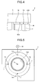
- FIG. 4 is an enlarged view illustrating a rotation mechanism according to a modified example of the first embodiment.
- FIG. 5 is a plan view illustrating the rotation mechanism according to the modified example of the first embodiment.
- FIG. 5 illustrates a state in which a rotation mechanism 1' is viewed from a position corresponding to the arrow A - A in FIG. 1 .
- the rotation mechanism 1' is substantially the same as the rotation mechanism 1 of the first embodiment, but different in not including the groove 8. Since the rotation mechanism 1' does not include the groove 8 illustrated in FIG. 3 and the like in the first member 2B, the gas passage 7 is directly opened to the surface 2BS of the first member 2B on the rotary member 5 side.
- the first member 2B of the rotation mechanism 1' includes a plurality of gas passages 7 (four in this example). In FIG. 5 , opening portions 7H in the respective gas passages 7 are illustrated.
- the gas contained in the gap 10 is exhausted to the outside of the housing 2 from the gas passages 7 by the exhaust device 50 in the rotation mechanism 1'. Therefore, the same operation and effects as the rotation mechanism 1 of the first embodiment can be obtained. Since the rotation mechanism 1' does not need to provide the groove 8 in the first member 2B, there is a merit that manufacturing becomes easy.
- gas having pressure higher than gas around the housing 2 may also be supplied to the gap 10 from the gas passages 7. Consequently, the gap 10 is sealed because the gas supplied from the gas passages 7 flows out to a radially outer side of the rotary member 5 and the first member 2B of the housing 2. As a result, entrance of liquid and the like into the gap 10 from the outside of the housing 2 can be suppressed.
- first embodiment and the modified example thereof have been described above, but the structures of the first embodiment and the modified example thereof can be suitably applied to following embodiments as well. In this case, only a partial structure of the first embodiment and the modified example thereof may be applied or all of the structures may be applied as well.
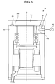
- FIG. 6 is a cross-sectional view illustrating a rotation mechanism according to a second embodiment.
- a rotation mechanism 1a of the second embodiment is the same as a rotation mechanism 1 of a first embodiment, but different in including a groove 8a in a rotary member 5a.
- Other structures of the rotation mechanism 1a are the same as the rotation mechanism 1.
- the groove 8a is provided on a surface 5SAa facing a surface 2BS of the first member 2B.
- the groove 8a is provided along in a circumferential direction of the rotary member 5a around a rotational center axis Zr.
- a gas passage 7 is opened at the surface 2BS included in the first member 2B and facing the rotary member 5a.
- the groove 8a is provided at a position facing an opening portion 7H of the gas passage 7.
- the rotation mechanism 1a includes the groove 8a in the rotary member 5a. Therefore, mass of the rotary member 5a is reduced by mass of the groove 8a. As a result, inertia moment of the rotary member 5a is reduced, thereby improving responsiveness of the rotary member 5a.
- the groove 8a is provided only in the rotary member 5a, but additionally a groove 8 as illustrated in FIGS. 1 , 2, and 3 may also be provided in a portion located in the first member 2B and facing the groove 8a. Consequently, exhaust efficiency of gas contained in a gap 10 is improved. Therefore, sealing performance can be more improved.
- the second embodiment has been described above, but the structure of the second embodiment can be suitably applied to following embodiments as well. In this case, only a partial structure of the second embodiment may be applied or all of the structures may be applied, too.
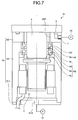
- FIG. 7 is a cross-sectional view illustrating a rotation mechanism according to a third embodiment.
- a rotation mechanism 1b of the third embodiment is the same as a rotation mechanism 1 of a first embodiment, but different in that gas is supplied to an electric motor 3 inside a housing 2b.
- Other structures of the rotation mechanism 1b are the same as the rotation mechanism 1.
- a second member 2Cb included in the housing 2b of the rotation mechanism 1b is attached to an end portion (the other end portion) on the electric motor 3 side housed in the housing 2b.
- the second member 2Cb included in the housing 2b of the rotation mechanism 1b includes a supply port 2CS.
- the supply port 2CS penetrates the second member 2Cb in a thickness direction thereof. From this supply port 2CS, gas is supplied to the electric motor 3 (in the present embodiment, air).
- a blower 51 is connected to the supply port 2CS.
- the blower 51 supplies gas to the electric motor 3 disposed inside the housing 2b via the supply port 2CS.
- the electric motor 3 is cooled by the gas.
- the gas supplied from the blower 51 also cools bearings 6A, 6B. Therefore, the rotation mechanism 1b can suppress heat deformation of the shaft 4. Since heat deformation of the shaft 4 is suppressed, the rotation mechanism 1b can rotate the shaft 4 at a high speed.
- the rotation mechanism 1b may connect the inside of the housing 2b not only to the supply port 2CS but also to a vacuum tank or a vacuum generating source with increasing airtightness of the housing 2b.
- the vacuum tank or the vacuum generating source can keep a vacuum state even in the case where an exhaust device 50 is stopped and a sealing function of the gap 10 cannot be kept in an emergency situation such as power failure.
- degradation of the sealing function by the gap 10 can be suppressed in the rotation mechanism 1b by connecting the inside of the housing 2b to the vacuum tank or the vacuum generating source at the time of power failure or the like.
- volume of the portion in the housing 2 in which the electric motor 3 is housed is formed small.
- the third embodiment has been described above, but the structure of the third embodiment can be suitably applied to following embodiments as well. In this case, only a partial structure of the third embodiment may be applied or all of the structures may be applied, too.
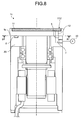
- FIG. 8 is a cross-sectional view illustrating a rotation mechanism according to a fourth embodiment.
- FIG. 8 shows a cross-section illustrating a rotation mechanism 1c taken along a plane including a rotational center axis Zr of the rotation mechanism 1c and parallel to the rotational center axis Zr.
- FIG. 9 is an enlarged view illustrating a gap in the rotation mechanism according to the fourth embodiment.
- FIG. 10 is a view taken along an arrow B - B in FIG. 8 .
- the rotation mechanism 1c of the fourth embodiment is the same as a rotation mechanism 1 of a first embodiment, but different in that a rotary member 5c includes a vacuum chuck mechanism. Other structures of the rotation mechanism 1c are the same as the rotation mechanism 1.
- the rotary member 5c of the rotation mechanism 1c includes a recessed portion 11U.
- a vacuum chuck 11 is provided at the recessed portion 11U.
- the rotary member 5c includes a through-hole 12 penetrating in a thickness direction.
- the through-hole 12 connects a first member 2B side of a housing 2 to the recessed portion 11U.
- the through-hole 12 is provided at a position located in the first member 2B and facing a groove 8.
- the first member 2B includes a plurality of through-holes 12 (four in the present example) along a circumferential direction of the first member 2B around the rotational center axis Zr.
- the number of through-holes 12 is not limited and may also be one.
- An exhaust device 50 sucks gas (for example, air) from the vacuum chuck 11 through a gas passage 7 provided at the first member 2B, the groove 8, a gap 10, and the through-hole 12 of the rotary member 5c. Then, an object loaded on the vacuum chuck 11 is adsorbed thereto. Further, the gap 10 exerts a sealing function by exhaust operation of the exhaust device 50. Thus, in the rotation mechanism 1c, a vacuum passage of the vacuum chuck 11 can be sealed by the gap 10.
- the vacuum chuck 11 may also be a porous body.
- the rotation mechanism 1c may provide the groove 8 at the rotary member 5c same as a second embodiment instead of providing the groove 8 at the first member 2B. Furthermore, the rotation mechanism 1c may include a supply port 2CS and a blower 51 to supply cooling gas to an electric motor 3 like a third embodiment.
- the fourth embodiment has been described above, but the structure of the fourth embodiment can be suitably applied to following embodiments as well. In this case, only a partial structure of the fourth embodiment may be applied or all of the structures may be applied, too.
- FIG. 11 is a cross-sectional view illustrating a rotation mechanism according to a fifth embodiment.
- FIG. 11 shows a cross-section illustrating a rotation mechanism 1d taken along a plane including a rotational center axis Zr of the rotation mechanism 1d and parallel to the rotational center axis Zr.
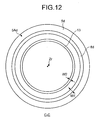
- FIG. 12 is a view taken along an arrow C - C in FIG. 11 .
- the rotation mechanism 1d of the fifth embodiment is the same as a rotation mechanism 1a of a second embodiment illustrated in FIG.
- the gas passage 7 will be conveniently referred to as a first gas passage 7 and the gas passage 14 different from the gas passage 7 will be conveniently referred to as a second gas passage 14.
- the groove 8d and the groove 13 are disposed extending in a circumferential direction of a hole 2BHd included in the first member 2Bd.
- the groove 8d and the groove 13 are provided on a surface 5Ad located in the rotary member 5d and facing a surface 2BS of the first member 2Bd in a radial direction of the hole 2BHd.
- the groove 8d is provided on a radially outer side of the groove 13.
- both of the groove 8d and the groove 13 are provided at the rotary member 5d, but both grooves may also be provided at the first member 2Bd of the housing 2d, or one of the grooves may be provided at the first member 2B and the other groove may be provided at the rotary member 5d.
- the rotation mechanism 1d may include the plurality of grooves in the radial direction of the hole 2BHd.
- the first gas passage 7 and the second gas passage 14 are opened at a surface 2BSd located in the first member 2Bd and facing the rotary member 5d.
- the groove 8d is provided at a position facing an opening portion 7H in the first gas passage 7.
- the groove 13 is provided at a position facing an opening portion 14H of the second gas passage 14.
- a width W1 of the groove 8 is larger than a width W2 of the groove 13 as illustrated in FIG. 12 , but a size relation between both grooves is not limited thereto.
- an exhaust device 52 is connected to the second gas passage 14.
- the exhaust device 52 sucks and exhausts gas contained inside the second gas passage 14 (in the present embodiment, air).
- the exhaust device 52 is, for example, a pump.
- the gas contained in the second gas passage 14 and the gas contained in the first gas passage 7 are respectively sucked by the different exhaust device 52 and exhaust device 50.
- the rotation mechanism 1d includes the plurality of grooves, the groove 8d and the groove 13 (two in the present embodiment) in the radial direction of the hole 2BHd included in the first member 2Bd of the housing 2d, thereby improving a sealing function.
- the exhaust device 50 and the exhaust device 52 suck gas contained in a gap 10 through the first gas passage 7 and the second gas passage 14.
- the gas contained in the gap 10 is exhausted to the outside of the housing 2d, thereby suppressing entrance of a foreign matter between a shaft 4 and the housing 2d from the outside of the rotation mechanism 1d, entrance of a foreign matter into the bearings 6A, 6B, and outflow of dust from the inside of the housing 2d to the outside of the rotation mechanism 1d.
- the rotation mechanism 1d can effectively suppress entrance of a foreign matter from the outside of the shaft 4 by the plurality of grooves, the groove 8d and the groove 13.
- Contamination in the gap 10 is caused by mist contained in an outside atmosphere of the housing 2d and liquid splashed toward the rotation mechanism 1d.
- the liquid may be, for example, cutting oil in a lathe, grinding liquid in a grinder, or the like in a machine tool, and polishing liquid, cleaning liquid, or the like in a semiconductor manufacturing device.
- the rotation mechanism 1d includes the groove 8d provided on the radially outer side of the hole 2BHd and the groove 13 provided on the radially inner side of the grooves 8d.
- the rotation mechanism 1d can be supplied with the cleaning liquid from the groove 8d located on the radially outer side, and can collect the cleaning liquid from the groove 8d located on the outer side of the housing 2d and the groove 13 located on the radially inner side. With this structure, the rotation mechanism 1d can suppress entrance of the cleaning liquid into the bearings 6A, 6B.
- the fifth embodiment has been described above, but the structure of the fifth embodiment can be suitably applied to following embodiments as well. In this case, only a partial structure of the fifth embodiment may be applied or all of the structures may be applied, too.
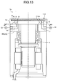
- FIG. 13 is a cross-sectional view illustrating a rotation mechanism according to a sixth embodiment.
- FIG. 13 shows a cross-section illustrating a rotation mechanism 1e taken along a plane including a rotational center axis Zr of the rotation mechanism 1e and parallel to the rotational center axis Zr.
- the rotation mechanism 1e of the sixth embodiment is the same as a rotation mechanism 1d of a fifth embodiment illustrated in FIG. 11 , but different in that a rotary member 5e includes a vacuum chuck mechanism.
- Other structures of the rotation mechanism 1e are the same as the rotation mechanism 1d.
- the rotary member 5e of the rotation mechanism 1e includes a recessed portion 11U.
- a vacuum chuck 11 is provided at the recessed portion 11U.
- the rotary member 5e includes a through-hole 12 penetrating in a thickness direction.
- the through-hole 12 connects a first member 2Be side of a housing 2e to the recessed portion 11U.
- the through-hole 12 is provided at a position facing the first gas passage 7 of the first member 2Be.
- the rotary member 5e includes a plurality of through-holes 12 (four in the present example) along a circumferential direction of the rotary member 5e around the rotational center axis Zr.
- the number of through-holes 12 is not limited and may also be one.
- An exhaust device 50 sucks gas (for example, air) from the vacuum chuck 11 through a first gas passage 7 provided at the first member 2Be, a gap 10, the groove 8e, and the through-hole 12 of the rotary member 5e. Then, an object loaded on the vacuum chuck 11 is adsorbed thereto. Furthermore, the gap 10 exerts a sealing function by exhaust operation of the exhaust device 50. Thus, the rotation mechanism 1e can seal a vacuum passage of the vacuum chuck 11 by the gap 10.
- the vacuum chuck 11 may also be a porous body.
- the rotation mechanism 1e can suck the gas from the vacuum chuck 11 through the first gas passage 7. Further, the rotation mechanism 1e can exhausts gas contained in the gap 10 from a second gas passage 14 different from the first gas passage 7. In this case, an exhaust device 52 sucks the gas from the second gas passage 14.
- an amount of the gas exhausted from the gap 10 is reduced in a gas passage for the vacuum chuck 11, namely, the first gas passage 7. As a result, a flow rate in an exhaust system of the vacuum chuck 11 can be reduced. Since pressure loss is reduced in the exhaust system of the vacuum chuck 11, pressure (chuck pressure) sucked by the vacuum chuck 11 can be increased.
- the rotation mechanism 1e can increase the chuck pressure to, for example, 1.1 times compared to a case of including only the first gas passage 7.
- the gap 10 can be formed large in the rotation mechanism 1e.
- the groove 8e and a groove 13 may be provided in a first member 2Be of a housing 2e same as a fifth embodiment instead of providing the groove 8e and the groove 13 in the rotary member 5e.
- the rotation mechanism 1e may provide either the groove 8e or the groove 13 in the rotary member 5e and may provide, in the housing 2e, the other groove out of the groove 8e or the groove 13 not provided in the rotary member 5e.
- the rotation mechanism 1e does not necessarily include both of the groove 8e and the groove 13.
- the through-hole 12 faces an opening portion of the first member 2Be of the first gas passage 7, and the second gas passage 14 sucks gas contained in a portion of the gap 10 from the opening portion of the first member 2Be.
- the exhaust device 52 can continue sucking the gas from the through-hole 12, the groove 8e, and the groove 13 provided on a radially inner side of the first gas passage 7. Therefore, even when the vacuum chuck 11 is turned off, the rotation mechanism 1e can exhaust the gas in the groove 13 flowing from the bearings 6A, 6B side from the through-hole 12 to the outside of the housing 2e.
- the rotation mechanism 1e can suppress outflow of the gas and dust contained on the bearings 6A, 6B side to the outside of the housing 2e.
- the sixth embodiment has been described above, but the structure of the sixth embodiment can be suitably applied to following embodiments as well. In this case, only a partial structure of the sixth embodiment may be applied or all of the structures may be applied, too.
- FIG. 14 is a cross-sectional view illustrating a rotation mechanism according to a seventh embodiment.
- FIG. 14 shows the cross-section illustrating a rotation mechanism 1f taken along a plane including a rotational center axis Zr of the rotation mechanism 1f and parallel to the rotational center axis Zr.
- the rotation mechanism 1f of the seventh embodiment is the same as a rotation mechanism 1a of a second embodiment illustrated in FIG. 6 , but different in that a housing 2f includes a passage 15 in order to suck gas from between the housing 2f and a shaft 4.
- a first member 2Bf includes the passage 15.
- the passage 15 is a passage extending in a radial direction of the first member 2Bf.
- the passage 15 passes through a side portion on a radially outer side of the first member 2Bf and a through-hole 2Hf, and connects the outside of the first member 2Bf to the inside of the through-hole 2Hf.
- the through-hole 2Hf includes, on an inner peripheral surface 2Hfw, a groove 16 extending in a circumferential direction of the through-hole 2Hf.
- the passage 15 is opened to the groove 16.
- the number of passage 15 is one, but the number of passage 15 is not limited thereto.
- an inner vacuum level can be relatively low. Therefore, the gap 10 in a portion provided with the groove 13 may have a relatively large size, for example, from several ⁇ m to several tens of ⁇ m as described above. Therefore, in the rotation mechanism 1f, the groove 16 is provided on the inner peripheral surface 2Hfw of the through-hole 2Hf instead of providing the groove 13 at the rotary member 5a or the first member 2Bf. Furthermore, an exhaust device 52 sucks gas from between the first member 2Bf of the housing 2f and the shaft 4 through the passage 15 opened to the groove 16.
- the exhaust device 52 sucks the gas from between the first member 2Bf and the shaft 4 through the passage 15 while the gap 10 is cleaned with cleaning liquid. Therefore, entrance of the cleaning liquid into bearings 6A, 6B can be suppressed.
- the groove 16 is provided on the inner peripheral surface 2Hfw of the through-hole 2Hf, but the groove 16 is not necessarily provided at the through-hole 2Hf.
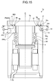
- FIG. 15 is a cross-sectional view illustrating a rotation mechanism according to an eighth embodiment.
- FIG. 15 shows a cross-section illustrating a rotation mechanism 1g taken along a plane including a rotational center axis Zr of the rotation mechanism 1g and parallel to the rotational center axis Zr.
- the rotation mechanism 1g of the eighth embodiment includes a gas passage 7 and a supply passage 18.
- the gas passage 7 connects a gap 10 to outside of a housing 2g, and allows gas contained in the gap 10 portion to pass to the outside of the housing 2g.
- the gas passage 7 will be conveniently referred to as an exhaust passage 7.
- the supply passage 18 connects the gap 10 to the outside of the housing 2g, and supplies gas to the portion of the gap 10 from a more radially outer side of a hole 2BHg than the gas passage 7.
- the supply passage 18 connects the surface 2BS located in a first member 2Bg and facing a rotary member 5g to a side portion 2BE linked to the surface 2BS, and the supply passage 18 passes through the first member 2Bg.
- the supply passage 18 is opened to the surface 2BS located in the first member 2Bg and facing the rotary member 5g.
- the supply passage 18 connects the gap 10 to the outside of the housing 2g and supplies gas to the portion of the gap 10.
- a supply device 54 is connected to the supply passage 18.
- the supply device 54 supplies gas (in the present embodiment, air) to the supply passage 18.
- the supply device 54 is a pump, for example, and supplies the supply passage 18 with the gas having pressure higher than a periphery of the housing 2g.
- a portion located in the rotary member 5g and facing the first member 2Bg of the housing 2g, namely, a surface 5Ag of the rotary member 5g is provided with a first groove 8g and a second groove 17.
- Both of the first groove 8g and the second groove 17 extend in a circumferential direction of the hole 2BHg.
- the second groove 17 is provided on a more radially outer side of the hole 2BHg than the first groove 8g.
- both of the first groove 8g and the second groove 17 are concentric around the rotational center axis Zr.
- An opening portion 7H of the exhaust passage 7 faces the first groove 8g, and an opening portion 18H of the supply passage 18 faces the second groove 17.
- the exhaust passage 7 connects the gap 10 to the outside of the housing 2g at a position of the first groove 8g, and the supply passage 18 connects the gap 10 to the outside of the housing 2g at a position of the second groove 17.
- both of the first groove 8g and the second groove 17 are provided at the rotary member 5g, but may also be provided at the first member 2Bg included in the housing 2g.
- first groove 8g and the second groove 17 may also be provided at least one of a portion located in the first member 2Bg of the housing 2g and facing the rotary member 5g, and a portion located in the rotary member 5g and facing the first member 2Bg of the Housing 2g.
- the opening portion 18H at the first member 2Bg of the supply passage 18 is opened on a more radially outer side of the hole 2BHg than the opening portion 7H at the first member 2Bg of the exhaust passage 7.
- the rotation mechanism 1g can suppress entrance of a foreign matter such as liquid from the outside of the housing 2g into the gap 10 and the radially inner side of the second groove 17 with the gas supplied by the supply device 54 to the gap 10 through the second groove 17 from the supply passage 18.
- An exhaust device 50 sucks high-pressure gas supplied to the gap 10 from the supply passage 18 through the exhaust passage 7 and the first groove 8g, and exhausts the gas from the same the gap 10 to the outside of the housing 2g. Therefore, the rotation mechanism 1g can suppress the high-pressure gas supplied from the supply passage 18 from flowing into the bearing 6A, 6B inside the housing 2g.
- the rotation mechanism 1g does not necessarily include the first groove 8g and the second groove 17.
- the rotation mechanism 1g can efficiently fill the high-pressure gas to the gap 10 across the rotary member 5g and an entire peripheral area of the first member 2Bg of the housing 2g, and furthermore can effectively exhaust the gas from the gap 10. Therefore, it is preferable to include the first groove 8g and the second groove 17.
- a width Wi of the first groove 8g is larger than a width Wo of the second groove 17.
- the gap 10 on the radially outer side of the second groove 17 is larger than a gap on the radially inner side of the second groove 17.
- the rotation mechanism 1g can effectively emit, to the outside of the housing 2g, the gas supplied to the second groove 17.
- the rotation mechanism 1g may include a vacuum chuck 11 illustrated in FIG. 13 .
- a through-hole 12 illustrated in FIG. 13 is connected to the first groove 8g.
- An exhaust device 50 can adsorb an object to the vacuum chuck 11 by sucking the gas through the through-hole 12, first groove 8g, and exhaust passage 7 illustrated in FIG. 13 .
- the rotation mechanism 1g provides high performance to seal the inside of the housing 2g. Therefore, use in an environment in which liquid is sprayed to the shaft 4 is preferable. Furthermore, the rotation mechanism 1g is suitable to be used in a case of an environment in which the gap 10 is formed small due to gas or liquid sucked from the periphery of the housing 2g is accumulated on the first member 2Bg of the housing 2g or a surface of the rotary member 5g.
- the eighth embodiment has been described above, but the structure of the eighth embodiment can be suitably applied to following embodiments as well. In this case, only a partial structure of the eighth embodiment may be applied or all of the structures may be applied, too.
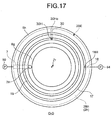
- FIG. 16 is a cross-sectional view illustrating a rotation mechanism according to a ninth embodiment.
- FIG. 17 is a view taken along an arrow D - D in FIG. 16 .
- This rotation mechanism 1h is the same as a rotation mechanism 1g of an eighth embodiment, but different in including a third groove 19 between a first groove 8g and a second groove 17.
- Other structures of the rotation mechanism 1h are the same as the rotation mechanism 1g.
- the third groove 19 extends in a circumferential direction of a hole 2BHh, and is connected to outside of a first member 2Bh of a housing 2h.
- the third groove 19 is provided on a surface 5Ah located in a rotary member 5h and facing the first member 2Bh of the housing 2h, but may also be provided on a surface 2BS located in the first member 2Bh of the housing 2h and facing the rotary member 5h.
- the third groove 19 may also be provided on the surface 5Ah of the rotary member 5h and the surface 2BS of the first member 2Bh of the housing 2h.
- the third groove 19 is provided in at least one of a portion located in the housing 2h and facing the rotary member 5h, and a portion located in the rotary member 5h and facing the housing 2h.
- the first member 2Bh of the housing 2h includes a passage 30.
- the first member 2Bh includes an opening portion 30Hi of the passage 30 at a portion facing the third groove 19.
- the first member 2Bh includes an opening portion 30Ho of the passage 30 at a side portion 2BE.
- the passage 30 allows communication between a gap 10, which is located between the rotary member 5h and the first member 2Bh of the housing 2h, and the outside of the first member 2Bh of the housing 2h illustrated in FIG. 16 .
- a flow rate of gas that flows to an exhaust passage 7 from the first groove 8g (hereinafter, conveniently referred to as exhausting flow rate) is increased in accordance with pressure of high-pressure gas supplied from a supply passage 18 to the second groove 17.
- the third groove 19 collects the high-pressure gas flowing out from the second groove 17 and emits the gas from the passage 30 to the outside of the housing 2h. Therefore, the third groove 19 can reduce the exhausting flow rate.
- the rotation mechanism 1h of the present embodiment can efficiently emit the gas supplied from the second groove 17 to the outside of the housing 2h without forming the gap 10 on a radially outer side larger than the gap 10 on a radially inner side of the second groove 17.
- the rotation mechanism 1h may include a vacuum chuck 11 illustrated in FIG. 13 .
- a through-hole 12 illustrated in FIG. 13 is connected to the first groove 8g.
- An exhaust device 50 can adsorb an object to the vacuum chuck 11 by sucking the gas through the through-hole 12, first groove 8g, and exhaust passage 7 illustrated in FIG. 13 . Since the rotation mechanism 1h can reduce the exhausting flow rate by the third groove 19, chuck pressure can be increased if exhausting performance of the exhaust device 50 is equal to those in a case without the third groove 19. When the chuck pressure is equal to those in a case without the third groove 19, the exhaust performance of the exhaust device 50 can be small.
- the ninth embodiment has been described above, but the structure of the ninth embodiment can be suitably applied to following embodiment as well. In this case, only a partial structure of the ninth embodiment may be applied or all of the structures may be applied, too.
- FIG. 18 is a cross-sectional view illustrating a rotation mechanism according to a tenth embodiment.
- the rotation mechanism 1i includes, in a housing 2i, an opening portion 22 opened on a more radially outer side of a hole 2BHi than an exhaust passage 7, facing a rotary member 5i, and extending in a circumferential direction of the hole 2BHi.
- a supply passage 18i is connected to the opening portion 22.
- a first member 2Bi of the housing 2i included in the rotation mechanism 1i include, on a side portion 2BE, a recessed portion 2BU formed in a circumferential direction.
- An annular member 20 is attached to the recessed portion 2BU.
- the annular member 20 contacts an outer peripheral surface 2Bsw of the recessed portion 2BU on a second member 2Ci side of the housing 2i.
- a gap 22S is formed in a space between the rotation mechanism 1i side of the annular member 20 and the outer peripheral surface 2Bsw of the recessed portion 2BU.
- This gap 22S is formed as the opening portion 22 opened to a surface 2BS located in the first member 2Bi of the housing 2i on the rotary member 5i side.
- a slot throttle of a gas bearing can be utilized for the gap 22S.
- the annular member 20 includes a groove 21 formed on an inner peripheral surface along a circumferential direction.
- the groove 21 is connected to the gap 22S and the supply passage 18i.
- a supply device 54 supplies gas to the gap 22S through the groove 21 from the supply passage 18i
- the gas can be uniformly injected from the opening portion 22 to between the rotary member 5i and the first member 2Bi in circumferential directions thereof.
- the gap 22S and the opening portion 22 can uniformly inject the gas in the circumferential directions of the rotary member 5i and the first member 2Bi.
- the gas is emitted to the outside of the housing 2i, thereby achieving sealing.
- an adjustment apparatus to control a flow rate of the gas flowing into the gap 22S can be provided at the supply passage 18i or a passage connected thereto.
- the rotary member 5i includes a groove 8i extending in a circumferential direction of the hole 2BHi on a surface 5Ai located in the rotary member 5i and facing the first member 2Bi of the housing 2i.
- the groove 8i may also be provided on the surface 2BS located in the first member 2Bi of the housing 2i and facing the rotary member 5i, and may also be provided at both of the rotary member 5i and the first member 2Bi.
- An opening portion 7H of the exhaust passage 7 faces the groove 8i, and an exhaust device 50 sucks gas contained inside a gap 10 and the groove 8i through the exhaust passage 7.
- the rotation mechanism 1i includes a gap 23 between the rotary member 5i and the annular member 20.
- the gap 23 is connected to the opening portion 22.
- the rotation mechanism 1g can reduce a flow rate of high-pressure gas which is supplied from the supply passage 18i to flow into the exhaust passage 7 through the groove 8i.
- the rotation mechanism 1i can reduce diameters of a rotary member 5h and a first member 2Bh of a housing 2h, compared to a rotation mechanism 1h of a ninth embodiment illustrated in FIG. 16 .
- the first to tenth embodiments have been described above, the first to tenth embodiments are not limited by the matters described above. Furthermore, the above-described components include those readily conceivable by men skilled in the art, those substantially identical therewith, and those included in a so-called equivalent range. Moreover, the above-described components can be suitably combined. Additionally, at least one of various kinds of omission, replacement, and modifications can be made with respect to the components in a range without departing from the gist of the first to tenth embodiments.
Landscapes
- Engineering & Computer Science (AREA)
- General Engineering & Computer Science (AREA)
- Mechanical Engineering (AREA)
- Power Engineering (AREA)
- Sealing Using Fluids, Sealing Without Contact, And Removal Of Oil (AREA)
- Container, Conveyance, Adherence, Positioning, Of Wafer (AREA)
Abstract
Description
- The present invention relates to a rotation mechanism, a machine tool, and a semiconductor manufacturing device.
- In a conveyance device, a semiconductor manufacturing device, a machine tool, or the like, a rotation mechanism that rotates a rotary stage or rotates a tool or a workpiece is used. As such a rotation mechanism, for example, a spindle with static pressure gas bearing is disclosed in
Patent Literature 1. According to this spindle with static pressure gas bearing, a chuck sleeve and a bearing sleeve are vertically fitted into a sleeve fitting hole of a housing, and an exhaust space formed between both of the sleeves is made to communicate with the outside through an exhaust passage provided at the housing. A table for supporting a workpiece is fitted to an upper end of a main spindle. The chuck sleeve is provided with a suction passage in communication with a workpiece adsorption recessed portion formed at the table. Compressed gas supplied into a radial bearing gap between the main spindle and the bearing sleeve is exhausted to the outside from the exhaust space and the exhaust passage. - Patent Literature 1:
Japanese Laid-open Patent Publication No. 7-217655 - According to the technology disclosed in
Patent Literature 1, in the case where compressed gas flows into a gap between a chuck sleeve and a main spindle, the compressed gas is prevented from flowing out over the housing by sucking the compressed gas into a suction passage formed at the chuck sleeve, thereby preventing dust contained in the compressed gas supporting the main spindle from adhering to a surface of a workpiece placed on a table. However, a foreign matter may enter between the main spindle and the chuck sleeve from the outside of the main spindle, and may affect supporting of the main spindle. - The present invention is directed to suppressing entrance of a foreign matter from the outside of a shaft included in a rotation mechanism.
- According to the present invention, there is provided a rotation mechanism comprising: a housing; a shaft inserted through a hole provided at the housing; a bearing installed at the housing and configured to rotatably support the shaft; a rotary member provided at one end portion of the shaft, configured to be rotated together with the shaft, and having a portion that projects to a radially outer side of the hole and faces the housing with a gap having a predetermined size; and a gas passage configured to connect the gap to outside of the housing and allow gas contained in a portion of the gap to pass to the outside of the housing.
- In the rotation mechanism, the portion of the rotary member that projects to radially outer side of the hole into which the shaft is inserted faces the housing with the gap having the predetermined size, and allows the gas contained in the portion of the gap to pass to the outside of the housing from the gas passage. With this structure, the rotation mechanism exhausts the gas contained in the gap from a more outer side of the rotation mechanism than a portion between the hole and shaft. Therefore, entrance of a foreign matter from the outside of the shaft can be suppressed.
- Preferably, the bearing is a rolling bearing including an outer ring, an inner ring disposed on a radially inner side of the outer ring, and a rolling element disposed between the outer ring and the inner ring, and a space surrounded by the hole and the shaft is opened on the rotary member side and between the outer ring and the inner ring. With this structure, the gas contained inside the housing is exhausted to the outside of the housing, passing through between the outer ring and the inner ring of the bearing, the space, gap, and the gas passage. Thus, since the space surrounded by the hole and shaft can exhaust heat generated at the bearing to the outside of the housing, temperature increase at the bearing can be suppressed.
- Preferably, the housing includes, inside, an electric motor having a rotor connected to the other end portion of the shaft, and cooling gas is supplied to the electric motor. With this structure, temperature increase at the electric motor can be suppressed.
- Preferably, a groove extending in a circumferential direction of the hole is provided in at least one of a portion located in the housing and facing the rotary member and a portion located in the rotary member and facing the housing, and the gas passage connects the gap to the outside of the housing at a position of the groove. Since the groove is provided around the hole, the gas contained in the gap is exhausted to the outside of the housing from the entire groove. Due to this operation, entrance of a foreign matter and outflow of the dust contained inside the housing can be effectively suppressed in the rotation mechanism.
- Preferably, the groove is provided at a portion located in the housing and facing the rotary member, and the gas passage is provided in the housing and opened to the groove. Consequently, entrance of a foreign matter and outflow of the dust contained inside the housing can be effectively suppressed.
- Preferably, a plurality of the grooves is provided in a radial direction of the hole. The rotation mechanism includes the plurality of grooves in the radial direction of the housing, thereby improving sealing function. Moreover, the rotation mechanism can effectively suppress entrance of a foreign matter from the outside of the shaft by the plurality of grooves. Furthermore, when the gap between the rotary member and the housing is cleaned with liquid such as cleaning liquid, the cleaning liquid can be supplied from the grooves on outer side, and the cleaning liquid can be collected from the grooves on the outer side and an inner side of the housing. With this structure, the rotation mechanism can suppress entrance of the cleaning liquid into the bearing.
- Preferably, the groove is provided at a portion located in the rotary member and facing the housing, and the gas passage is provided in the housing and opened to a position located in the housing and facing the groove. With this structure, mass of the rotary member is reduced. Therefore, inertia moment of the rotary member can be reduced.
- Preferably, a plurality of the grooves is provided in a radial direction of the hole. The rotation mechanism includes the plurality of grooves in the radial direction of the housing, thereby improving sealing function. Moreover, the rotation mechanism can effectively suppress entrance of a foreign matter from the outside of the shaft by the plurality of grooves. Furthermore, when the gap between the rotary member and the housing is cleaned with liquid such as cleaning liquid, the cleaning liquid can be supplied from the grooves on outer side, and the cleaning liquid can be collected from the grooves on the outer side and an inner side of the housing. With this structure, the rotation mechanism can suppress entrance of the cleaning liquid to the bearing.
- Preferably, a through-hole penetrating the rotary member in a thickness direction is provided, and gas is exhausted from the rotary member on an opposite side of the housing through the through-hole, the gap, and the gas passage. With this structure, an adsorption mechanism such as a vacuum chuck can be provided at the rotary member by utilizing the gas passage.
- Preferably, the housing includes other gas passage different from the gas passage, and the other gas passage different from the gas passage allows gas contained in a portion of the gap to pass to the outside of the housing. In the case where the adsorption mechanism such as the vacuum chuck is provided at the rotary member, the rotation mechanism sucks, from the gas passage, the gas from a suction mechanism and can exhaust the gas contained in the gap from the gas passage to the outside of the housing. Since the gas contained in the gap is exhausted also from the other gas passage, an exhausting amount of the gas from the gap is reduced in the gas passage for the adsorption mechanism. As a result, a flow rate at an exhaust system of the adsorption mechanism can be reduced. Furthermore, since pressure loss at the exhaust system of the adsorption mechanism is reduced, chuck pressure can be increased.
- Preferably, the housing includes a passage to suck gas from between the housing and the shaft. Entrance of the cleaning liquid on the bearing side can be suppressed by sucking the gas from between the housing and the shaft while the gap is cleaned with the cleaning liquid.
- Preferably, the rotation mechanism includes a supply passage configured to connect the gap to the outside of the housing and supply gas to a portion of the gap from a portion located on a more radially outer side of the hole than the gas passage. The rotation mechanism can suppress entrance of a foreign matter such as liquid from the outside of the housing into the radially inner side of the gap by the gas supplied to the gap from the supply passage. Furthermore, since the gas from the supply passage is exhausted from the gas passage to the outside of the housing, the rotation mechanism can suppress high-pressure gas supplied from the supply passage from flowing into the inside of the housing.
- Preferably, the rotation mechanism includes a first groove provided at least at one of a portion located in the housing and facing the rotary member and a portion located in the rotary member and facing the housing, and extending in a circumferential direction of the hole; and a second groove provided at least at one of a portion located in the housing and facing the rotary member and a portion located in the rotary member and facing the housing, and disposed on a more radially outer side of the hole than the first groove, and extending in a circumferential direction of the hole, wherein the gas passage connects the gap to the outside of the housing at a position of the first groove, and the supply passage connects the gap to the outside of the housing at a portion of the second groove. The rotation mechanism can efficiently fill the high-pressure gas to the gap across a rotary member and an entire peripheral area of the housing, and also can efficiently exhaust the gas from the gap, by using the first groove and the second groove.
- Preferably, the rotation mechanism includes a third groove provided at least at one of a portion located in the housing and facing the rotary member and a portion located in the rotary member and facing the housing, and also the third groove being positioned between the first groove and the second groove, extending in a circumferential direction of the hole, and being connected to the outside of the housing. In the rotation mechanism, the high-pressure gas flowing out to the gap from the supply passage is collected in the third groove and can be emitted to the outside of the housing. Therefore, a flow rate of the high-pressure gas supplied from the supply passage to flow in the gas passage can be reduced.
- Preferably, the rotation mechanism includes, in the housing, an opening portion opened on a more radially outer side of the hole than the gas passage, facing the rotary member, and extending in a circumferential direction of the hole, wherein the supply passage is connected to the opening portion. In the rotation mechanism, the high-pressure gas supplied from the supply passage through the opening portion is exhausted to the radially outer side of the housing. Therefore, a flow rate of the high-pressure gas flowing in the exhaust passage can be reduced after supplied from the supply passage.
- A machine tool according to the present invention includes the above-described rotation mechanism. Therefore, entrance of a foreign matter from outside of a shaft included in the machine tool can be suppressed.
- A semiconductor manufacturing device according to the present invention includes the above-described rotation mechanism. Therefore, entrance of a foreign matter from outside of a shaft included in the semiconductor manufacturing device can be suppressed.
- The present invention can suppress entrance of a foreign matter from the outside of the shaft included in the rotation mechanism.
-
-
FIG. 1 is a cross-sectional view illustrating a rotation mechanism according to a first embodiment. -
FIG. 2 is an enlarged view illustrating a gap in the rotation mechanism according to the first embodiment. -
FIG. 3 is a view taken along an arrow A - A inFIG. 1 . -
FIG. 4 is an enlarged view illustrating a rotation mechanism according to a modified example of the first embodiment. -
FIG. 5 is a plan view illustrating the rotation mechanism according to the modified example of the first embodiment. -
FIG. 6 is a cross-sectional view illustrating a rotation mechanism according to a second embodiment. -
FIG. 7 is a cross-sectional view illustrating a rotation mechanism according to a third embodiment. -
FIG. 8 is a cross-sectional view illustrating a rotation mechanism according to a fourth embodiment. -
FIG. 9 is an enlarged view illustrating a gap in the rotation mechanism according to the fourth embodiment. -
FIG. 10 is a view taken along an arrow B - B inFIG. 8 . -
FIG. 11 is a cross-sectional view illustrating a rotation mechanism according to a fifth embodiment. -
FIG. 12 is a view taken along an arrow C - C inFIG. 11 . -
FIG. 13 is a cross-sectional view illustrating a rotation mechanism according to a sixth embodiment. -
FIG. 14 is a cross-sectional view illustrating a rotation mechanism according to a seventh embodiment. -
FIG. 15 is a cross-sectional view illustrating a rotation mechanism according to an eighth embodiment. -
FIG. 16 is a cross-sectional view illustrating a rotation mechanism according to a ninth embodiment. -
FIG. 17 is a view taken along an arrow D - D inFIG. 16 . -
FIG. 18 is a cross-sectional view illustrating a rotation mechanism according to a tenth embodiment. - In the following, modes to implement the present invention (hereinafter referred to as embodiments) will be described with reference to the drawings.
-
FIG. 1 is a cross-sectional view illustrating a rotation mechanism according to a first embodiment.FIG. 1 shows a cross-section illustrating arotation mechanism 1 taken along a plane including a rotational center axis Zr of therotation mechanism 1 and parallel to the rotational center axis Zr.FIG. 2 is an enlarged view illustrating a gap in the rotation mechanism according to the first embodiment.FIG. 3 is a view taken along an arrow A - A inFIG. 1 . Therotation mechanism 1 is a machine element that transmits rotation, and is applied to, for example, in a machine tool, a conveyance device used under a special environment such as a vacuum chamber, a semiconductor manufacturing device, a flat panel display manufacturing device, or the like. Here, as an example, a description will be given for a case where therotation mechanism 1 is a spindle unit including a spindle as a rotary shaft, but an object to which therotation mechanism 1 is applied is not limited thereto. - The
rotation mechanism 1 includes a housing 2, ashaft 4,bearings rotary member 5, and agas passage 7. The housing 2 is a member to house thebearings side portion 2A having a cylindrical shape, afirst member 2B provided at one end portion of theside portion 2A, and asecond member 2C provided at the other end portion of theside portion 2A. Theside portion 2A,first member 2B, andsecond member 2C constitute part of the housing 2. In the present embodiment, theside portion 2A is a cylindrical member, and includes a through-hole 2I that runs from one end portion to the other end portion, more specifically, from thefirst member 2B to thesecond member 2C. - Both of the
first member 2B and thesecond member 2C are plate-like members. In the present embodiment, thefirst member 2B and thesecond member 2C each have a circle shape in a planar view, but the shape is not limited thereto. Thefirst member 2B includes the rotational center axis Zr of theshaft 4, and also includes a hole 2BH penetrating in a thickness direction. Thesecond member 2C includes a through-hole 2CH. Apower supply cable 3C is inserted through the through-hole 2CH. Thepower supply cable 3C supplies power to anelectric motor 3 provided inside the housing 2, more specifically, at a portion surrounded by theside portion 2A,first member 2B, andsecond member 2C. - The
shaft 4 is an output shaft of therotation mechanism 1 and passes through thefirst member 2B by being inserted into the housing 2, more specifically, the hole 2BH provided at thefirst member 2B of the housing 2. Thebearings shaft 4. In the present embodiment, theshaft 4 is supported at the housing 2 by the twobearings - The
bearings outer ring 6a, a rollingelement 6b, and aninner ring 6c. Theinner ring 6c is arranged on a radially inner side of theouter ring 6a. Thus, in the present embodiment, both of thebearings element 6b is disposed between theouter ring 6a and theinner ring 6c. Thebearings outer ring 6a contacting aninner wall 2W of the through-hole 2I included in theside portion 2A of the housing 2. With this structure, thebearings bearings bearings bearings - The
rotary member 5 is provided at one end portion 4TA of theshaft 4, and is rotated together with theshaft 4. Therotary member 5 has an object loaded on a surface 5SB located on an opposite side of the one end portion 4TA of theshaft 4. In the present embodiment, therotary member 5 is a plate-like member and has a circle shape in a planar view. Therotary member 5 projects to a radially outer side of the hole 2BH provided at thefirst member 2B of the housing 2. Aportion 5F that projects to the radially outer side of the hole 2BH (hereinafter, conveniently referred to as a flange portion) faces the housing 2 with apredetermined gap 10 as illustrated inFIG. 2 . - The
gap 10 is formed between a surface 2BS of thefirst member 2B included in the housing 2 and facing therotary member 5 and a surface 5SA located at therotary member 5 and facing thefirst member 2B. Thegap 10 is a sealing portion to seal a space between the inside and the outside of the housing 2. Thegap 10 illustrated inFIG. 2 has a size t from several µm to several tens of µm, for example. - The
gas passage 7 is provided at a portion located in the housing 2 and facing therotary member 5, more specifically, thefirst member 2B of the housing 2. Thegas passage 7 connects a surface 2BS located in thefirst member 2B and facing therotary member 5 to a side portion 2BE linked to the surface 2BS, and the gas passage passes through thefirst member 2B. With this structure, thegas passage 7 connects thegap 10 to the outside of the housing 2, and allows gas contained in thegap 10 portion to pass to the outside of the housing 2. In the present embodiment, anexhaust device 50 is connected to thegas passage 7. Theexhaust device 50 sucks and exhausts the gas contained inside the gas passage 7 (in the present embodiment, air). Theexhaust device 50 is, for example, a pump. - In the present embodiment, as illustrated in
FIGS. 1 ,2, and 3 , agroove 8 is formed on the surface 2BS that is a portion of thefirst member 2B included in the housing 2 and faces therotary member 5. Thegroove 8 extends in a circumferential direction of the hole 2BH included in thefirst member 2B as illustrated inFIG. 3 . Further, as illustrated inFIGS. 1 ,2, and 3 , thegas passage 7 is opened to thegroove 8. More specifically, thegas passage 7 is opened to a bottom portion of thegroove 8. InFIG. 3 , anopening portion 7H of thegas passage 7 is illustrated. - In the present embodiment, the number of
gas passage 7 included in therotation mechanism 1 is one, but the number thereof is not limited thereto. In the case where therotation mechanism 1 includes a plurality ofgas passages 7, preferably, thegas passages 7 are provided at equal intervals around the rotational center axis Zr. The gas contained in thegap 10 passes and is exhausted from thegas passage 7 to the outside of the housing 2, and exhausting balance of the gas is improved by disposing the plurality ofgas passages 7 at equal intervals. Therefore, disposing the plurality ofgas passages 7 at equal intervals is preferable. - The
electric motor 3 is provided inside the housing 2. Theelectric motor 3 includes arotor 3R, and astator 3S provided on a radially outer side of therotor 3R. Thestator 3S is attached to theinner wall 2W of the through-hole 2I included in theside portion 2A. Therotor 3R is connected to the other end portion of theshaft 4. With this structure, therotor 3R,shaft 4 androtary member 5 are integrally rotated around the rotational center axis Zr. In the present embodiment, a form of theelectric motor 3 is not limited. - In the present embodiment, as described above, the gas contained in the
gap 10 is exhausted from thegas passage 7 to the outside of the housing 2, thereby suppressing entrance of a foreign matter into between theshaft 4 and the housing 2 from the outside of therotation mechanism 1, entrance of a foreign matter into thebearings rotation mechanism 1. The dust flowing out from the inside of the housing 2 may include dust from thebearings electric motor 3, for example. As described later, therotation mechanism 1 does not necessarily include thegroove 8, but since thegroove 8 is provided around the hole 2BH, the gas contained in thegap 10 is exhausted from theentire groove 8 to the outside of the housing. Due to this action, entrance of a foreign matter and outflow of the dust contained inside the housing 2 can be effectively suppressed in therotation mechanism 1. Therefore, in therotation mechanism 1, a mechanical bearing, such as a rolling bearing or a slide bearing, which does not require any gas supply can be used for thebearings - In the case of using the rolling bearings for the
bearings shaft 4 in a direction of thegap 10 caused by a reason other than a load from an object loaded on therotary member 5 is suppressed. Therefore, sealing performance can be improved by making the size t of thegap 10 small. The size t of thegap 10 is determined while allowing predetermined tolerance relative to accuracy of the shaft 4 (deflection in a sealing surface direction), flatness and perpendicularity with respect to theshaft 4 of the sealing surface on the housing 2 side. The mentioned sealing surface is, on the housing 2 side, the surface 2BS of thefirst member 2B located on therotary member 5 side, and also on therotary member 5 side, is the surface 5SA of therotary member 5 located on thefirst member 2B side. - In the
rotation mechanism 1, theinner ring 6c of the bearing 6A contacts anannular spacer 9 which is provided atshaft 4 on therotary member 5 side. Therotary member 5 and theshaft 4 are fastened and fixed with a bolt BLT, for example, as illustrated inFIG. 1 . Thespacer 9 is disposed between the bearing 6A and therotary member 5. In thebearing 6A, theouter ring 6a contacts thefirst member 2B of the housing 2. Furthermore, theinner ring 6c of thebearing 6A contacts theinner ring 6c of thebearing 6B, and also theannular spacer 4S contacts theinner ring 6c of thebearing 6B. In this state, alock nut 4N is screwed into theshaft 4 from thespacer 4S side. Thespacer 4S is disposed at theshaft 4 on theelectric motor 3 side. - Since the
lock nut 4N is screwed and fastened, thebearings spacer 4S and thespacer 9 and furthermore between thelock nut 4N and therotary member 5. When thebearings inner wall 2W of theside portion 2A of the housing 2, theouter ring 6a of thebearing 6A contacts thefirst member 2B of the housing 2. Then a position of theshaft 4 is determined in the rotational center axis Zr direction. Thus, in therotation mechanism 1, reference of theshaft 4 in the rotational center axis Zr direction is located on therotary member 5 side. With this structure, there is a merit that a posture and a position of therotary member 5 and the size t of thegap 10 are hardly affected by heat deformation of theshaft 4, such as extension in the rotational center axis Zr direction. - In the present embodiment, the
shaft 4 and thebearings bearings inner wall 2W of theside portion 2A. Next, therotary member 5 is attached to the one end portion 4TA with thespacer 9 being attached to theshaft 4 on the one end portion 4TA side. In this state, theshaft 4 is made to pass through the hole 2BH of thefirst member 2B of the housing 2 from the other end portion thereof, and inserted into theinner ring 6c of thebearings shaft 4 is inserted into thebearings spacer 4S is attached to theshaft 4, and then thelock nut 4N is screwed from the other end portion of theshaft 4 to attach theshaft 4 to thebearings - The
spacer 9 and theshaft 4 are disposed inside the hole 2BH of thefirst member 2B of the housing 2. In the present embodiment, thespacer 9 and thespacer 4S attached to theshaft 4 are also deemed as the part of the shaft. A space surrounded by the hole 2BH andspacer 9, namely, theshaft 4 is opened to therotary member 5 side of thefirst member 2B and also between theouter ring 6a and theinner ring 6c in each of thebearings gap 10 to an area between theouter ring 6a and theinner ring 6c in each of thebearings gap 10 through the space, passing through the area between theouter ring 6a and theinner ring 6c in each of thebearings gap 10 is sucked and exhausted by theexhaust device 50, thereby allowing the gas contained inside the housing 2 to be exhausted to the outside of the housing 2 through the area between theouter ring 6a and theinner ring 6c in each of thebearings gap 10, andgas passage 7. Thus, the above-described space can exhaust the heat generated at theelectric motor 3 and thebearings bearings shaft 4 is suppressed, therotation mechanism 1 can achieve high rotation accuracy. Furthermore, since the above-described heat deformation is suppressed, therotation mechanism 1 can allow theelectric motor 3 and theshaft 4 to be rotated with high acceleration/deceleration or at a high speed accompanying heat generation. - In the
rotation mechanism 1, the rolling bearings are used for thebearings bearings outer ring 6a attached to theinner wall 2W of theside portion 2A of the housing 2 and theinner ring 6c attached to theshaft 4. In this structure, a gap between theshaft 4 and the hole 2BH provided at thefirst member 2B of the housing 2 is needed to be controlled in order to secure sealing inside the housing 2. To achieve this, an axial center on the housing 2 side and an axial center of theshaft 4 supported by thebearings rotation mechanism 1, it is effective to form thegap 10 between therotary member 5 and thefirst member 2B of the housing 2 in order to improve sealing efficiency. - When gas supply is stopped by power failure or the like, the hydrostatic bearing loses a function as the bearing. Therefore, in the case of providing a sealing gap between the
first member 2B and therotary member 5, the sealing gap is needed to be formed larger than a gap of the hydrostatic bearing. Therefore, in the case of using the hydrostatic bearing, the sealing gap is hardly formed smaller than a predetermined size. In the present embodiment, thebearings rotation mechanism 1, in the case of using the rolling bearings for thebearings gap 10 can be formed small in a range that therotary member 5 does not contact thefirst member 2B. Consequently, sealing efficiency is improved. - In the
rotation mechanism 1, preferably, a diameter of therotary member 5 is set larger than a diameter of thefirst member 2B of the housing 2 in order to suppress entrance of a liquid-state foreign matter into thegap 10 while rotation of theshaft 4 is stopped. Thegap 10 may also be cleaned by, for example, supplying cleaning liquid such as solvent from a passage connected to thegroove 8, such as thegas passage 7 or a passage provided separately from thegas passage 7. In the present embodiment, theside portion 2A and thefirst member 2B are separate components in the housing 2, but not limited to this structure. For instance, theside portion 2A and thefirst member 2B are may be manufactured as an integrated structure by a manufacturing method such as casting. -
FIG. 4 is an enlarged view illustrating a rotation mechanism according to a modified example of the first embodiment.FIG. 5 is a plan view illustrating the rotation mechanism according to the modified example of the first embodiment.FIG. 5 illustrates a state in which a rotation mechanism 1' is viewed from a position corresponding to the arrow A - A inFIG. 1 . The rotation mechanism 1' is substantially the same as therotation mechanism 1 of the first embodiment, but different in not including thegroove 8. Since the rotation mechanism 1' does not include thegroove 8 illustrated inFIG. 3 and the like in thefirst member 2B, thegas passage 7 is directly opened to the surface 2BS of thefirst member 2B on therotary member 5 side. As illustrated inFIG. 5 , in the present modified example, thefirst member 2B of the rotation mechanism 1' includes a plurality of gas passages 7 (four in this example). InFIG. 5 , openingportions 7H in therespective gas passages 7 are illustrated. - With this structure also, the gas contained in the
gap 10 is exhausted to the outside of the housing 2 from thegas passages 7 by theexhaust device 50 in the rotation mechanism 1'. Therefore, the same operation and effects as therotation mechanism 1 of the first embodiment can be obtained. Since the rotation mechanism 1' does not need to provide thegroove 8 in thefirst member 2B, there is a merit that manufacturing becomes easy. - Furthermore, gas having pressure higher than gas around the housing 2 may also be supplied to the
gap 10 from thegas passages 7. Consequently, thegap 10 is sealed because the gas supplied from thegas passages 7 flows out to a radially outer side of therotary member 5 and thefirst member 2B of the housing 2. As a result, entrance of liquid and the like into thegap 10 from the outside of the housing 2 can be suppressed. - The first embodiment and the modified example thereof have been described above, but the structures of the first embodiment and the modified example thereof can be suitably applied to following embodiments as well. In this case, only a partial structure of the first embodiment and the modified example thereof may be applied or all of the structures may be applied as well.
-
FIG. 6 is a cross-sectional view illustrating a rotation mechanism according to a second embodiment. Arotation mechanism 1a of the second embodiment is the same as arotation mechanism 1 of a first embodiment, but different in including agroove 8a in arotary member 5a. Other structures of therotation mechanism 1a are the same as therotation mechanism 1. - In the
rotary member 5a of therotation mechanism 1a, thegroove 8a is provided on a surface 5SAa facing a surface 2BS of thefirst member 2B. Thegroove 8a is provided along in a circumferential direction of therotary member 5a around a rotational center axis Zr. Agas passage 7 is opened at the surface 2BS included in thefirst member 2B and facing therotary member 5a. Thegroove 8a is provided at a position facing anopening portion 7H of thegas passage 7. - The
rotation mechanism 1a includes thegroove 8a in therotary member 5a. Therefore, mass of therotary member 5a is reduced by mass of thegroove 8a. As a result, inertia moment of therotary member 5a is reduced, thereby improving responsiveness of therotary member 5a. In the present embodiment, thegroove 8a is provided only in therotary member 5a, but additionally agroove 8 as illustrated inFIGS. 1 ,2, and 3 may also be provided in a portion located in thefirst member 2B and facing thegroove 8a. Consequently, exhaust efficiency of gas contained in agap 10 is improved. Therefore, sealing performance can be more improved. - The second embodiment has been described above, but the structure of the second embodiment can be suitably applied to following embodiments as well. In this case, only a partial structure of the second embodiment may be applied or all of the structures may be applied, too.
-
FIG. 7 is a cross-sectional view illustrating a rotation mechanism according to a third embodiment. Arotation mechanism 1b of the third embodiment is the same as arotation mechanism 1 of a first embodiment, but different in that gas is supplied to anelectric motor 3 inside ahousing 2b. Other structures of therotation mechanism 1b are the same as therotation mechanism 1. - A second member 2Cb included in the
housing 2b of therotation mechanism 1b is attached to an end portion (the other end portion) on theelectric motor 3 side housed in thehousing 2b. The second member 2Cb included in thehousing 2b of therotation mechanism 1b includes a supply port 2CS. The supply port 2CS penetrates the second member 2Cb in a thickness direction thereof. From this supply port 2CS, gas is supplied to the electric motor 3 (in the present embodiment, air). - In the present embodiment, a
blower 51 is connected to the supply port 2CS. Theblower 51 supplies gas to theelectric motor 3 disposed inside thehousing 2b via the supply port 2CS. Theelectric motor 3 is cooled by the gas. Furthermore, the gas supplied from theblower 51 also coolsbearings rotation mechanism 1b can suppress heat deformation of theshaft 4. Since heat deformation of theshaft 4 is suppressed, therotation mechanism 1b can rotate theshaft 4 at a high speed. - The
rotation mechanism 1b may connect the inside of thehousing 2b not only to the supply port 2CS but also to a vacuum tank or a vacuum generating source with increasing airtightness of thehousing 2b. The vacuum tank or the vacuum generating source can keep a vacuum state even in the case where anexhaust device 50 is stopped and a sealing function of thegap 10 cannot be kept in an emergency situation such as power failure. With this structure, degradation of the sealing function by thegap 10 can be suppressed in therotation mechanism 1b by connecting the inside of thehousing 2b to the vacuum tank or the vacuum generating source at the time of power failure or the like. In the case of using this structure, preferably, volume of the portion in the housing 2 in which theelectric motor 3 is housed is formed small. - The third embodiment has been described above, but the structure of the third embodiment can be suitably applied to following embodiments as well. In this case, only a partial structure of the third embodiment may be applied or all of the structures may be applied, too.
-
FIG. 8 is a cross-sectional view illustrating a rotation mechanism according to a fourth embodiment.FIG. 8 shows a cross-section illustrating a rotation mechanism 1c taken along a plane including a rotational center axis Zr of the rotation mechanism 1c and parallel to the rotational center axis Zr.FIG. 9 is an enlarged view illustrating a gap in the rotation mechanism according to the fourth embodiment.FIG. 10 is a view taken along an arrow B - B inFIG. 8 . The rotation mechanism 1c of the fourth embodiment is the same as arotation mechanism 1 of a first embodiment, but different in that arotary member 5c includes a vacuum chuck mechanism. Other structures of the rotation mechanism 1c are the same as therotation mechanism 1. - The
rotary member 5c of the rotation mechanism 1c includes a recessedportion 11U. Avacuum chuck 11 is provided at the recessedportion 11U. Furthermore, therotary member 5c includes a through-hole 12 penetrating in a thickness direction. The through-hole 12 connects afirst member 2B side of a housing 2 to the recessedportion 11U. The through-hole 12 is provided at a position located in thefirst member 2B and facing agroove 8. In the present embodiment, thefirst member 2B includes a plurality of through-holes 12 (four in the present example) along a circumferential direction of thefirst member 2B around the rotational center axis Zr. The number of through-holes 12 is not limited and may also be one. - An
exhaust device 50 sucks gas (for example, air) from thevacuum chuck 11 through agas passage 7 provided at thefirst member 2B, thegroove 8, agap 10, and the through-hole 12 of therotary member 5c. Then, an object loaded on thevacuum chuck 11 is adsorbed thereto. Further, thegap 10 exerts a sealing function by exhaust operation of theexhaust device 50. Thus, in the rotation mechanism 1c, a vacuum passage of thevacuum chuck 11 can be sealed by thegap 10. Thevacuum chuck 11 may also be a porous body. - The rotation mechanism 1c may provide the
groove 8 at therotary member 5c same as a second embodiment instead of providing thegroove 8 at thefirst member 2B. Furthermore, the rotation mechanism 1c may include a supply port 2CS and ablower 51 to supply cooling gas to anelectric motor 3 like a third embodiment. - The fourth embodiment has been described above, but the structure of the fourth embodiment can be suitably applied to following embodiments as well. In this case, only a partial structure of the fourth embodiment may be applied or all of the structures may be applied, too.
-
FIG. 11 is a cross-sectional view illustrating a rotation mechanism according to a fifth embodiment.FIG. 11 shows a cross-section illustrating arotation mechanism 1d taken along a plane including a rotational center axis Zr of therotation mechanism 1d and parallel to the rotational center axis Zr.FIG. 12 is a view taken along an arrow C - C inFIG. 11 . Therotation mechanism 1d of the fifth embodiment is the same as arotation mechanism 1a of a second embodiment illustrated inFIG. 6 , but different in that a plurality of grooves, agroove 8d and agroove 13, is provided at arotary member 5d and agas passage 7 as well as agas passage 14 different from thegas passage 7 are provided at a first member 2Bd of ahousing 2d. Other structures of therotation mechanism 1d are the same as therotation mechanism 1a. In the following, thegas passage 7 will be conveniently referred to as afirst gas passage 7 and thegas passage 14 different from thegas passage 7 will be conveniently referred to as asecond gas passage 14. - As illustrated in
FIGS. 11 and12 , thegroove 8d and thegroove 13 are disposed extending in a circumferential direction of a hole 2BHd included in the first member 2Bd. Thegroove 8d and thegroove 13 are provided on a surface 5Ad located in therotary member 5d and facing a surface 2BS of the first member 2Bd in a radial direction of the hole 2BHd. In the present embodiment, thegroove 8d is provided on a radially outer side of thegroove 13. In the present embodiment, both of thegroove 8d and thegroove 13 are provided at therotary member 5d, but both grooves may also be provided at the first member 2Bd of thehousing 2d, or one of the grooves may be provided at thefirst member 2B and the other groove may be provided at therotary member 5d. Thus, therotation mechanism 1d may include the plurality of grooves in the radial direction of the hole 2BHd. - The
first gas passage 7 and thesecond gas passage 14 are opened at a surface 2BSd located in the first member 2Bd and facing therotary member 5d. Thegroove 8d is provided at a position facing anopening portion 7H in thefirst gas passage 7. Thegroove 13 is provided at a position facing anopening portion 14H of thesecond gas passage 14. In the present embodiment, a width W1 of thegroove 8 is larger than a width W2 of thegroove 13 as illustrated inFIG. 12 , but a size relation between both grooves is not limited thereto. - In the present embodiment, an
exhaust device 52 is connected to thesecond gas passage 14. Theexhaust device 52 sucks and exhausts gas contained inside the second gas passage 14 (in the present embodiment, air). Theexhaust device 52 is, for example, a pump. Thus, the gas contained in thesecond gas passage 14 and the gas contained in thefirst gas passage 7 are respectively sucked by thedifferent exhaust device 52 andexhaust device 50. - In the present embodiment, the
rotation mechanism 1d includes the plurality of grooves, thegroove 8d and the groove 13 (two in the present embodiment) in the radial direction of the hole 2BHd included in the first member 2Bd of thehousing 2d, thereby improving a sealing function. Theexhaust device 50 and theexhaust device 52 suck gas contained in agap 10 through thefirst gas passage 7 and thesecond gas passage 14. The gas contained in thegap 10 is exhausted to the outside of thehousing 2d, thereby suppressing entrance of a foreign matter between ashaft 4 and thehousing 2d from the outside of therotation mechanism 1d, entrance of a foreign matter into thebearings housing 2d to the outside of therotation mechanism 1d. Thus, therotation mechanism 1d can effectively suppress entrance of a foreign matter from the outside of theshaft 4 by the plurality of grooves, thegroove 8d and thegroove 13. - Contamination in the
gap 10 is caused by mist contained in an outside atmosphere of thehousing 2d and liquid splashed toward therotation mechanism 1d. The liquid may be, for example, cutting oil in a lathe, grinding liquid in a grinder, or the like in a machine tool, and polishing liquid, cleaning liquid, or the like in a semiconductor manufacturing device. Therotation mechanism 1d includes thegroove 8d provided on the radially outer side of the hole 2BHd and thegroove 13 provided on the radially inner side of thegrooves 8d. Therefore, when thegap 10 between therotary member 5d and thehousing 2d is cleaned with cleaning liquid or the like, therotation mechanism 1d can be supplied with the cleaning liquid from thegroove 8d located on the radially outer side, and can collect the cleaning liquid from thegroove 8d located on the outer side of thehousing 2d and thegroove 13 located on the radially inner side. With this structure, therotation mechanism 1d can suppress entrance of the cleaning liquid into thebearings - The fifth embodiment has been described above, but the structure of the fifth embodiment can be suitably applied to following embodiments as well. In this case, only a partial structure of the fifth embodiment may be applied or all of the structures may be applied, too.
-
FIG. 13 is a cross-sectional view illustrating a rotation mechanism according to a sixth embodiment.FIG. 13 shows a cross-section illustrating arotation mechanism 1e taken along a plane including a rotational center axis Zr of therotation mechanism 1e and parallel to the rotational center axis Zr. Therotation mechanism 1e of the sixth embodiment is the same as arotation mechanism 1d of a fifth embodiment illustrated inFIG. 11 , but different in that arotary member 5e includes a vacuum chuck mechanism. Other structures of therotation mechanism 1e are the same as therotation mechanism 1d. - The
rotary member 5e of therotation mechanism 1e includes a recessedportion 11U. Avacuum chuck 11 is provided at the recessedportion 11U. Furthermore, therotary member 5e includes a through-hole 12 penetrating in a thickness direction. The through-hole 12 connects a first member 2Be side of ahousing 2e to the recessedportion 11U. The through-hole 12 is provided at a position facing thefirst gas passage 7 of the first member 2Be. In the present embodiment, therotary member 5e includes a plurality of through-holes 12 (four in the present example) along a circumferential direction of therotary member 5e around the rotational center axis Zr. The number of through-holes 12 is not limited and may also be one. - An
exhaust device 50 sucks gas (for example, air) from thevacuum chuck 11 through afirst gas passage 7 provided at the first member 2Be, agap 10, thegroove 8e, and the through-hole 12 of therotary member 5e. Then, an object loaded on thevacuum chuck 11 is adsorbed thereto. Furthermore, thegap 10 exerts a sealing function by exhaust operation of theexhaust device 50. Thus, therotation mechanism 1e can seal a vacuum passage of thevacuum chuck 11 by thegap 10. Thevacuum chuck 11 may also be a porous body. - In the case of providing an adsorption mechanism such as the
vacuum chuck 11 in therotary member 5e, therotation mechanism 1e can suck the gas from thevacuum chuck 11 through thefirst gas passage 7. Further, therotation mechanism 1e can exhausts gas contained in thegap 10 from asecond gas passage 14 different from thefirst gas passage 7. In this case, anexhaust device 52 sucks the gas from thesecond gas passage 14. With this structure, an amount of the gas exhausted from thegap 10 is reduced in a gas passage for thevacuum chuck 11, namely, thefirst gas passage 7. As a result, a flow rate in an exhaust system of thevacuum chuck 11 can be reduced. Since pressure loss is reduced in the exhaust system of thevacuum chuck 11, pressure (chuck pressure) sucked by thevacuum chuck 11 can be increased. For example, flow rates in thefirst gas passage 7 andsecond gas passage 14 become substantially half by providing thesecond gas passage 14. Therefore, pressure loss inside thefirst gas passage 7 and inside thesecond gas passage 14 is reduced. In the case of obtaining relatively high chuck pressure, therotation mechanism 1e can increase the chuck pressure to, for example, 1.1 times compared to a case of including only thefirst gas passage 7. In the case of requiring the chuck pressure equal to chuck pressure in the case of including only thefirst gas passage 7, thegap 10 can be formed large in therotation mechanism 1e. - In the
rotation mechanism 1e, thegroove 8e and agroove 13 may be provided in a first member 2Be of ahousing 2e same as a fifth embodiment instead of providing thegroove 8e and thegroove 13 in therotary member 5e. Also, therotation mechanism 1e may provide either thegroove 8e or thegroove 13 in therotary member 5e and may provide, in thehousing 2e, the other groove out of thegroove 8e or thegroove 13 not provided in therotary member 5e. Furthermore, in the present embodiment, therotation mechanism 1e does not necessarily include both of thegroove 8e and thegroove 13. In this case, the through-hole 12 faces an opening portion of the first member 2Be of thefirst gas passage 7, and thesecond gas passage 14 sucks gas contained in a portion of thegap 10 from the opening portion of the first member 2Be. - Even when gas suction by the
exhaust device 50 is temporarily stopped, theexhaust device 52 can continue sucking the gas from the through-hole 12, thegroove 8e, and thegroove 13 provided on a radially inner side of thefirst gas passage 7. Therefore, even when thevacuum chuck 11 is turned off, therotation mechanism 1e can exhaust the gas in thegroove 13 flowing from thebearings hole 12 to the outside of thehousing 2e. Therotation mechanism 1e can suppress outflow of the gas and dust contained on thebearings housing 2e. - The sixth embodiment has been described above, but the structure of the sixth embodiment can be suitably applied to following embodiments as well. In this case, only a partial structure of the sixth embodiment may be applied or all of the structures may be applied, too.
-
FIG. 14 is a cross-sectional view illustrating a rotation mechanism according to a seventh embodiment.FIG. 14 shows the cross-section illustrating arotation mechanism 1f taken along a plane including a rotational center axis Zr of therotation mechanism 1f and parallel to the rotational center axis Zr. Therotation mechanism 1f of the seventh embodiment is the same as arotation mechanism 1a of a second embodiment illustrated inFIG. 6 , but different in that ahousing 2f includes apassage 15 in order to suck gas from between thehousing 2f and ashaft 4. - The
housing 2f of therotation mechanism 1f, in the present embodiment, a first member 2Bf includes thepassage 15. Thepassage 15 is a passage extending in a radial direction of the first member 2Bf. Thepassage 15 passes through a side portion on a radially outer side of the first member 2Bf and a through-hole 2Hf, and connects the outside of the first member 2Bf to the inside of the through-hole 2Hf. In the present embodiment, the through-hole 2Hf includes, on an inner peripheral surface 2Hfw, agroove 16 extending in a circumferential direction of the through-hole 2Hf. Thepassage 15 is opened to thegroove 16. In the present embodiment, the number ofpassage 15 is one, but the number ofpassage 15 is not limited thereto. - In a
groove 13 of a sixth embodiment described above, an inner vacuum level can be relatively low. Therefore, thegap 10 in a portion provided with thegroove 13 may have a relatively large size, for example, from several µm to several tens of µm as described above. Therefore, in therotation mechanism 1f, thegroove 16 is provided on the inner peripheral surface 2Hfw of the through-hole 2Hf instead of providing thegroove 13 at therotary member 5a or the first member 2Bf. Furthermore, anexhaust device 52 sucks gas from between the first member 2Bf of thehousing 2f and theshaft 4 through thepassage 15 opened to thegroove 16. For example, theexhaust device 52 sucks the gas from between the first member 2Bf and theshaft 4 through thepassage 15 while thegap 10 is cleaned with cleaning liquid. Therefore, entrance of the cleaning liquid intobearings groove 16 is provided on the inner peripheral surface 2Hfw of the through-hole 2Hf, but thegroove 16 is not necessarily provided at the through-hole 2Hf. -
FIG. 15 is a cross-sectional view illustrating a rotation mechanism according to an eighth embodiment.FIG. 15 shows a cross-section illustrating a rotation mechanism 1g taken along a plane including a rotational center axis Zr of the rotation mechanism 1g and parallel to the rotational center axis Zr. The rotation mechanism 1g of the eighth embodiment includes agas passage 7 and asupply passage 18. Thegas passage 7 connects agap 10 to outside of ahousing 2g, and allows gas contained in thegap 10 portion to pass to the outside of thehousing 2g. In the following, thegas passage 7 will be conveniently referred to as anexhaust passage 7. Thesupply passage 18 connects thegap 10 to the outside of thehousing 2g, and supplies gas to the portion of thegap 10 from a more radially outer side of a hole 2BHg than thegas passage 7. - The
supply passage 18 connects the surface 2BS located in a first member 2Bg and facing arotary member 5g to a side portion 2BE linked to the surface 2BS, and thesupply passage 18 passes through the first member 2Bg. Thesupply passage 18 is opened to the surface 2BS located in the first member 2Bg and facing therotary member 5g. With this structure, thesupply passage 18 connects thegap 10 to the outside of thehousing 2g and supplies gas to the portion of thegap 10. In the present embodiment, asupply device 54 is connected to thesupply passage 18. Thesupply device 54 supplies gas (in the present embodiment, air) to thesupply passage 18. Thesupply device 54 is a pump, for example, and supplies thesupply passage 18 with the gas having pressure higher than a periphery of thehousing 2g. - In the present embodiment, a portion located in the
rotary member 5g and facing the first member 2Bg of thehousing 2g, namely, a surface 5Ag of therotary member 5g is provided with afirst groove 8g and asecond groove 17. Both of thefirst groove 8g and thesecond groove 17 extend in a circumferential direction of the hole 2BHg. Thesecond groove 17 is provided on a more radially outer side of the hole 2BHg than thefirst groove 8g. In the present embodiment, both of thefirst groove 8g and thesecond groove 17 are concentric around the rotational center axis Zr. - An
opening portion 7H of theexhaust passage 7 faces thefirst groove 8g, and anopening portion 18H of thesupply passage 18 faces thesecond groove 17. Theexhaust passage 7 connects thegap 10 to the outside of thehousing 2g at a position of thefirst groove 8g, and thesupply passage 18 connects thegap 10 to the outside of thehousing 2g at a position of thesecond groove 17. In the present embodiment, both of thefirst groove 8g and thesecond groove 17 are provided at therotary member 5g, but may also be provided at the first member 2Bg included in thehousing 2g. More specifically, thefirst groove 8g and thesecond groove 17 may also be provided at least one of a portion located in the first member 2Bg of thehousing 2g and facing therotary member 5g, and a portion located in therotary member 5g and facing the first member 2Bg of theHousing 2g. - The
opening portion 18H at the first member 2Bg of thesupply passage 18 is opened on a more radially outer side of the hole 2BHg than theopening portion 7H at the first member 2Bg of theexhaust passage 7. With this structure, the rotation mechanism 1g can suppress entrance of a foreign matter such as liquid from the outside of thehousing 2g into thegap 10 and the radially inner side of thesecond groove 17 with the gas supplied by thesupply device 54 to thegap 10 through thesecond groove 17 from thesupply passage 18. Anexhaust device 50 sucks high-pressure gas supplied to thegap 10 from thesupply passage 18 through theexhaust passage 7 and thefirst groove 8g, and exhausts the gas from the same thegap 10 to the outside of thehousing 2g. Therefore, the rotation mechanism 1g can suppress the high-pressure gas supplied from thesupply passage 18 from flowing into the bearing 6A, 6B inside thehousing 2g. - The rotation mechanism 1g does not necessarily include the
first groove 8g and thesecond groove 17. However, by providing thefirst groove 8g and thesecond groove 17, the rotation mechanism 1g can efficiently fill the high-pressure gas to thegap 10 across therotary member 5g and an entire peripheral area of the first member 2Bg of thehousing 2g, and furthermore can effectively exhaust the gas from thegap 10. Therefore, it is preferable to include thefirst groove 8g and thesecond groove 17. - In the present embodiment, a width Wi of the
first groove 8g is larger than a width Wo of thesecond groove 17. With this structure, theexhaust passage 7 can suck the gas contained in thegap 10 from a wide area in the radial direction of thefirst groove 8g. Therefore, liquid, gas, or the like can be effectively suppressed from being directed to thebearings first groove 8g. - Preferably, the
gap 10 on the radially outer side of thesecond groove 17 is larger than a gap on the radially inner side of thesecond groove 17. With this structure, the rotation mechanism 1g can effectively emit, to the outside of thehousing 2g, the gas supplied to thesecond groove 17. - The rotation mechanism 1g may include a
vacuum chuck 11 illustrated inFIG. 13 . In this case, a through-hole 12 illustrated inFIG. 13 is connected to thefirst groove 8g. Anexhaust device 50 can adsorb an object to thevacuum chuck 11 by sucking the gas through the through-hole 12,first groove 8g, andexhaust passage 7 illustrated inFIG. 13 . - The rotation mechanism 1g provides high performance to seal the inside of the
housing 2g. Therefore, use in an environment in which liquid is sprayed to theshaft 4 is preferable. Furthermore, the rotation mechanism 1g is suitable to be used in a case of an environment in which thegap 10 is formed small due to gas or liquid sucked from the periphery of thehousing 2g is accumulated on the first member 2Bg of thehousing 2g or a surface of therotary member 5g. - The eighth embodiment has been described above, but the structure of the eighth embodiment can be suitably applied to following embodiments as well. In this case, only a partial structure of the eighth embodiment may be applied or all of the structures may be applied, too.
-
FIG. 16 is a cross-sectional view illustrating a rotation mechanism according to a ninth embodiment.FIG. 17 is a view taken along an arrow D - D inFIG. 16 . Thisrotation mechanism 1h is the same as a rotation mechanism 1g of an eighth embodiment, but different in including athird groove 19 between afirst groove 8g and asecond groove 17. Other structures of therotation mechanism 1h are the same as the rotation mechanism 1g. - The
third groove 19 extends in a circumferential direction of a hole 2BHh, and is connected to outside of a first member 2Bh of ahousing 2h. In the present embodiment, thethird groove 19 is provided on a surface 5Ah located in arotary member 5h and facing the first member 2Bh of thehousing 2h, but may also be provided on a surface 2BS located in the first member 2Bh of thehousing 2h and facing therotary member 5h. Thethird groove 19 may also be provided on the surface 5Ah of therotary member 5h and the surface 2BS of the first member 2Bh of thehousing 2h. Thus, thethird groove 19 is provided in at least one of a portion located in thehousing 2h and facing therotary member 5h, and a portion located in therotary member 5h and facing thehousing 2h. - As illustrated in
FIG. 17 , the first member 2Bh of thehousing 2h includes apassage 30. The first member 2Bh includes an opening portion 30Hi of thepassage 30 at a portion facing thethird groove 19. Further, the first member 2Bh includes an opening portion 30Ho of thepassage 30 at a side portion 2BE. With this structure, thepassage 30 allows communication between agap 10, which is located between therotary member 5h and the first member 2Bh of thehousing 2h, and the outside of the first member 2Bh of thehousing 2h illustrated inFIG. 16 . - A flow rate of gas that flows to an
exhaust passage 7 from thefirst groove 8g (hereinafter, conveniently referred to as exhausting flow rate) is increased in accordance with pressure of high-pressure gas supplied from asupply passage 18 to thesecond groove 17. Thethird groove 19 collects the high-pressure gas flowing out from thesecond groove 17 and emits the gas from thepassage 30 to the outside of thehousing 2h. Therefore, thethird groove 19 can reduce the exhausting flow rate. Therotation mechanism 1h of the present embodiment can efficiently emit the gas supplied from thesecond groove 17 to the outside of thehousing 2h without forming thegap 10 on a radially outer side larger than thegap 10 on a radially inner side of thesecond groove 17. - The
rotation mechanism 1h may include avacuum chuck 11 illustrated inFIG. 13 . In this case, a through-hole 12 illustrated inFIG. 13 is connected to thefirst groove 8g. Anexhaust device 50 can adsorb an object to thevacuum chuck 11 by sucking the gas through the through-hole 12,first groove 8g, andexhaust passage 7 illustrated inFIG. 13 . Since therotation mechanism 1h can reduce the exhausting flow rate by thethird groove 19, chuck pressure can be increased if exhausting performance of theexhaust device 50 is equal to those in a case without thethird groove 19. When the chuck pressure is equal to those in a case without thethird groove 19, the exhaust performance of theexhaust device 50 can be small. - The ninth embodiment has been described above, but the structure of the ninth embodiment can be suitably applied to following embodiment as well. In this case, only a partial structure of the ninth embodiment may be applied or all of the structures may be applied, too.
-
FIG. 18 is a cross-sectional view illustrating a rotation mechanism according to a tenth embodiment. Therotation mechanism 1i includes, in ahousing 2i, an openingportion 22 opened on a more radially outer side of a hole 2BHi than anexhaust passage 7, facing a rotary member 5i, and extending in a circumferential direction of the hole 2BHi. Asupply passage 18i is connected to the openingportion 22. - A first member 2Bi of the
housing 2i included in therotation mechanism 1i include, on a side portion 2BE, a recessed portion 2BU formed in a circumferential direction. Anannular member 20 is attached to the recessed portion 2BU. Theannular member 20 contacts an outer peripheral surface 2Bsw of the recessed portion 2BU on a second member 2Ci side of thehousing 2i. Agap 22S is formed in a space between therotation mechanism 1i side of theannular member 20 and the outer peripheral surface 2Bsw of the recessed portion 2BU. Thisgap 22S is formed as the openingportion 22 opened to a surface 2BS located in the first member 2Bi of thehousing 2i on the rotary member 5i side. For example, a slot throttle of a gas bearing can be utilized for thegap 22S. - The
annular member 20 includes agroove 21 formed on an inner peripheral surface along a circumferential direction. Thegroove 21 is connected to thegap 22S and thesupply passage 18i. When asupply device 54 supplies gas to thegap 22S through thegroove 21 from thesupply passage 18i, the gas can be uniformly injected from the openingportion 22 to between the rotary member 5i and the first member 2Bi in circumferential directions thereof. For example, even in the case where the number of thesupply passage 18i is one, thegap 22S and the openingportion 22 can uniformly inject the gas in the circumferential directions of the rotary member 5i and the first member 2Bi. The gas is emitted to the outside of thehousing 2i, thereby achieving sealing. In the case of intending to increase a width of the openingportion 22 in order to uniformly inject the gas, an adjustment apparatus to control a flow rate of the gas flowing into thegap 22S can be provided at thesupply passage 18i or a passage connected thereto. - The rotary member 5i includes a
groove 8i extending in a circumferential direction of the hole 2BHi on a surface 5Ai located in the rotary member 5i and facing the first member 2Bi of thehousing 2i. Thegroove 8i may also be provided on the surface 2BS located in the first member 2Bi of thehousing 2i and facing the rotary member 5i, and may also be provided at both of the rotary member 5i and the first member 2Bi. Anopening portion 7H of theexhaust passage 7 faces thegroove 8i, and anexhaust device 50 sucks gas contained inside agap 10 and thegroove 8i through theexhaust passage 7. - The
rotation mechanism 1i includes agap 23 between the rotary member 5i and theannular member 20. Thegap 23 is connected to the openingportion 22. With this structure, the gas flowing out from the openingportion 22 is efficiently exhausted to the outside of thehousing 2i through thegap 23. Therefore, the rotation mechanism 1g can reduce a flow rate of high-pressure gas which is supplied from thesupply passage 18i to flow into theexhaust passage 7 through thegroove 8i. Further, therotation mechanism 1i can reduce diameters of arotary member 5h and a first member 2Bh of ahousing 2h, compared to arotation mechanism 1h of a ninth embodiment illustrated inFIG. 16 . - While the first to tenth embodiments have been described above, the first to tenth embodiments are not limited by the matters described above. Furthermore, the above-described components include those readily conceivable by men skilled in the art, those substantially identical therewith, and those included in a so-called equivalent range. Moreover, the above-described components can be suitably combined. Additionally, at least one of various kinds of omission, replacement, and modifications can be made with respect to the components in a range without departing from the gist of the first to tenth embodiments.
-
- 1, 1a, 1b, 1c, 1d, 1e, 1f, 1g, 1h, 1i ROTATION MECHANISM
- 2, 2b, 2d, 2e, 2f, 2g, 2h, 2i HOUSING
- 2CS SUPPLY PORT
- 2BH, 2BHd HOLE
- 2A SIDE PORTION
- 2B, 2Bd, 2Be, 2Bf, 2Bg, 2Bh, 2Bi FIRST MEMBER
- 2C, 2Cb SECOND MEMBER
- 2I THROUGH-HOLE
- 2Hfw INNER PERIPHERAL SURFACE
- 3 ELECTRIC MOTOR
- 4 SHAFT
- 4S, 9 SPACER
- 5, 5a, 5c, 5d, 5e, 5g, 5h, 5i ROTARY MEMBER
- 5f PORTION THAT PROJECTS TO THE RADIALLY OUTER SIDE OF THE HOLE
- 6A, 6B BEARING
- 6a OUTER RING
- 6b ROLLING ELEMENT
- 6c INNER RING
- 7 GAS PASSAGE (FIRST GAS PASSAGE, EXHAUST PASSAGE)
- 7H OPENING PORTION
- 8, 8a, 8d, 8e, 8g, 8i, 13, 16 GROOVE
- 8g FIRST GROOVE
- 10, 22S, 23 GAP
- 11 VACUUM CHUCK
- 12 THROUGH-HOLE
- 14 GAS PASSAGE (SECOND GAS PASSAGE)
- 15 PASSAGE
- 17 SECOND GROOVE
- 18 SUPPLY PASSAGE
- 19 THIRD PASSAGE
- 20 ANNULAR MEMBER
- 22 OPENING PORTION
- 30 PASSAGE
- 50, 52 EXHAUST DEVICE
- 54 SUPPLY DEVICE
- 51 BLOWER
- BLT BOLT
- Zr ROTATIONAL CENTER AXIS
Claims (17)
- A rotation mechanism comprising:a housing;a shaft inserted through a hole provided at the housing;a bearing installed at the housing and configured to rotatably support the shaft;a rotary member provided at one end portion of the shaft, configured to be rotated together with the shaft, and having a portion that projects to a radially outer side of the hole and faces the housing with a gap having a predetermined size; anda gas passage configured to connect the gap to outside of the housing and allow gas contained in a portion of the gap to pass to the outside of the housing.
- The rotation mechanism according to claim 1, wherein
the bearing is a rolling bearing including an outer ring, an inner ring disposed on a radially inner side of the outer ring, and a rolling element disposed between the outer ring and the inner ring, and
a space surrounded by the hole and the shaft is opened between the outer ring and the inner ring on the rotary member side and. - The rotation mechanism according to claim 1 or 2, wherein
the housing includes, inside, an electric motor having a rotor connected to the other end portion of the shaft, and
cooling gas is supplied to the electric motor. - The rotation mechanism according to any one of claims 1 to 3, wherein
a groove extending in a circumferential direction of the hole is provided in at least one of a portion located in the housing and facing the rotary member and a portion located in the rotary member and facing the housing, and
the gas passage connects the gap to the outside of the housing at a position of the groove. - The rotation mechanism according to claim 4, wherein
the groove is provided at a portion located in the housing and facing the rotary member, and
the gas passage is provided in the housing and opened to the groove. - The rotation mechanism according to claim 5, wherein a plurality of the grooves is provided in a radial direction of the hole.
- The rotation mechanism according to claim 4, wherein
the groove is provided at a portion located in the rotary member and facing the housing, and
the gas passage is provided in the housing and opened to a position located in the housing and facing the groove. - The rotation mechanism according to claim 7, wherein a plurality of the grooves is provided in a radial direction of the hole.
- The rotation mechanism according to any one of claims 1 to 8, wherein
a through-hole penetrating the rotary member in a thickness direction is provided, and
gas is exhausted from the rotary member on an opposite side of the housing through the through-hole, the gap, and the gas passage. - The rotation mechanism according to claim 9, wherein
the housing includes other gas passage different from the gas passage, and
the other gas passage different from the gas passage allows gas contained in a portion of the gap to pass to the outside of the housing. - The rotation mechanism according to any one of claims 1 to 9, wherein the housing includes a passage to suck gas from between the housing and the shaft.
- The rotation mechanism according to any one of claims 1 to 3, including a supply passage configured to connect the gap to the outside of the housing and supply gas to a portion of the gap from a portion located on a more radially outer side of the hole than the gas passage.
- The rotation mechanism according to claim 12, including:a first groove provided at least at one of a portion located in the housing and facing the rotary member and a portion located in the rotary member and facing the housing, and extending in a circumferential direction of the hole; anda second groove provided at least at one of a portion located in the housing and facing the rotary member and a portion located in the rotary member and facing the housing, and disposed on a more radially outer side of the hole than the first groove, and extending in a circumferential direction of the hole,wherein the gas passage connects the gap to the outside of the housing at a position of the first groove, and the supply passage connects the gap to the outside of the housing at a portion of the second groove.
- The rotation mechanism according to claim 13, including a third groove provided at least at one of a portion located in the housing and facing the rotary member and a portion located in the rotary member and facing the housing, and also the third groove being positioned between the first groove and the second groove, extending in a circumferential direction of the hole, and being connected to the outside of the housing.
- The rotation mechanism according to claim 12, including, in the housing, an opening portion opened on a more radially outer side of the hole than the gas passage, facing the rotary member, and extending in a circumferential direction of the hole,
wherein the supply passage is connected to the opening portion. - A machine tool including a rotation mechanism according to any one of claims 1 to 15.
- A semiconductor manufacturing device including a rotation mechanism according to any one of claims 1 to 15.
Applications Claiming Priority (5)
| Application Number | Priority Date | Filing Date | Title |
|---|---|---|---|
| JP2014004632 | 2014-01-14 | ||
| JP2014013801A JP5796645B2 (en) | 2013-11-20 | 2014-01-28 | Rotating mechanism, machine tool and semiconductor manufacturing equipment |
| JP2014025850 | 2014-02-13 | ||
| JP2014045255A JP5800047B2 (en) | 2014-02-13 | 2014-03-07 | Rotating mechanism, machine tool and semiconductor manufacturing equipment |
| PCT/JP2014/084169 WO2015107845A1 (en) | 2014-01-14 | 2014-12-24 | Rotating mechanism, machine tool, and semiconductor production device |
Publications (2)
| Publication Number | Publication Date |
|---|---|
| EP3096049A1 true EP3096049A1 (en) | 2016-11-23 |
| EP3096049A4 EP3096049A4 (en) | 2017-07-05 |
Family
ID=56465471
Family Applications (1)
| Application Number | Title | Priority Date | Filing Date |
|---|---|---|---|
| EP14878718.7A Withdrawn EP3096049A4 (en) | 2014-01-14 | 2014-12-24 | Rotating mechanism, machine tool, and semiconductor production device |
Country Status (3)
| Country | Link |
|---|---|
| US (1) | US10788076B2 (en) |
| EP (1) | EP3096049A4 (en) |
| CN (1) | CN105814347A (en) |
Cited By (2)
| Publication number | Priority date | Publication date | Assignee | Title |
|---|---|---|---|---|
| CN113124055A (en) * | 2021-04-27 | 2021-07-16 | 北京工业大学 | Air-float thrust bearing based on radial dense-bead adsorption |
| EP4141281A1 (en) * | 2021-08-24 | 2023-03-01 | MI-Partners BV | Device with contactless heat transfer |
Families Citing this family (7)
| Publication number | Priority date | Publication date | Assignee | Title |
|---|---|---|---|---|
| WO2018029867A1 (en) * | 2016-08-08 | 2018-02-15 | 日本精工株式会社 | Motor, actuator, semiconductor manufacturing device, and flat display manufacturing device |
| CN108233669B (en) * | 2018-01-31 | 2024-08-09 | 江苏工大金凯高端装备制造有限公司 | Quick cutter servo device with quick cooling function |
| JP6810113B2 (en) * | 2018-09-07 | 2021-01-06 | ファナック株式会社 | Machine Tools |
| JP7306889B2 (en) * | 2019-06-21 | 2023-07-11 | ファナック株式会社 | Fixed member and spindle device |
| CN111364026B (en) * | 2020-05-27 | 2020-08-14 | 上海陛通半导体能源科技股份有限公司 | Reciprocating rotary CVD equipment and application method |
| CN116771799A (en) * | 2023-06-29 | 2023-09-19 | 南京康尼精密机械有限公司 | Rotary workbench formed by compounding static pressure plane bearing and turntable bearing |
| CN119635377B (en) * | 2024-12-27 | 2026-03-24 | 浙江卧龙精密动力系统有限公司 | A five-axis head C-axis rotation limit mechanism, a five-axis swivel head, and a five-axis machine tool |
Family Cites Families (42)
| Publication number | Priority date | Publication date | Assignee | Title |
|---|---|---|---|---|
| GB1345341A (en) * | 1971-03-03 | 1974-01-30 | Devac Ab | Percussion machine |
| US4075927A (en) * | 1975-11-06 | 1978-02-28 | Houdaille Industries, Inc. | Tool orienting and release mechanism for machine tool |
| GB2160451B (en) * | 1984-05-25 | 1987-07-08 | Citizen Watch Co Ltd | A rotary table unit |
| JPH0660692B2 (en) | 1986-02-27 | 1994-08-10 | 三菱重工業株式会社 | Sealing machine for rotating machinery |
| JPS63169253U (en) * | 1987-04-22 | 1988-11-04 | ||
| US5145298A (en) * | 1989-09-11 | 1992-09-08 | Optima Industries, Inc. | High speed drill spindle |
| US5239892A (en) | 1990-08-27 | 1993-08-31 | Mitutoyo Corporation | Rotating device |
| JPH0447937U (en) | 1990-08-27 | 1992-04-23 | ||
| US5139095A (en) * | 1991-09-27 | 1992-08-18 | Ingersoll-Rand Company | Method for removing debris from a drillhole |
| US5310341A (en) * | 1993-01-12 | 1994-05-10 | Byer Joseph I | Dental apparatus |
| JP3517263B2 (en) | 1994-02-03 | 2004-04-12 | Ntn株式会社 | Hydrostatic gas bearing spindle |
| JP3555634B2 (en) * | 1995-11-24 | 2004-08-18 | 豊田工機株式会社 | Spindle device |
| GB2337414A (en) * | 1998-05-14 | 1999-11-17 | Fujitsu Ltd | Soft handoff in cellular communications networks |
| JP2000018248A (en) | 1998-07-03 | 2000-01-18 | Shin Meiwa Ind Co Ltd | Bearing device and seal mechanism for bearing device |
| JP2000100907A (en) | 1998-09-17 | 2000-04-07 | Dainippon Screen Mfg Co Ltd | Substrate processing equipment |
| KR200207572Y1 (en) * | 1998-12-04 | 2001-01-15 | 이원해 | Soundproof Dustproof Device of Hydraulic Rock Drill |
| JP4069435B2 (en) | 1999-11-30 | 2008-04-02 | 日本精工株式会社 | Spindle seal device |
| JP2002061750A (en) * | 2000-08-24 | 2002-02-28 | Mitsutoyo Corp | Noncontact sealing device |
| CN2460801Y (en) | 2001-01-18 | 2001-11-21 | 王玉明 | Sealing device for spiral flute end capable of bidirectional rotation |
| JP4255706B2 (en) * | 2002-03-22 | 2009-04-15 | 東京エレクトロン株式会社 | Liquid processing equipment |
| JP2004197786A (en) * | 2002-12-17 | 2004-07-15 | Tamagawa Machinery Co Ltd | Thickener |
| JP2005249079A (en) | 2004-03-04 | 2005-09-15 | Nsk Ltd | Seal unit |
| JP4702799B2 (en) * | 2006-03-17 | 2011-06-15 | ルネサスエレクトロニクス株式会社 | Bolt and semiconductor manufacturing equipment |
| JP2008035604A (en) * | 2006-07-27 | 2008-02-14 | Sumitomo Heavy Ind Ltd | Gm freezer, pulse tube freezer, cryopump, mri device, super-conductive magnet system, nmr device, and freezer for cooling of semiconductor |
| JP2008175273A (en) * | 2007-01-17 | 2008-07-31 | Ntn Corp | Rolling bearing spindle and pattern correcting device |
| US8542705B2 (en) * | 2007-01-23 | 2013-09-24 | Mobitv, Inc. | Key frame detection and synchronization |
| JP5057843B2 (en) * | 2007-05-14 | 2012-10-24 | 津田駒工業株式会社 | Angle indexing device for machine tools |
| SE0702834L (en) * | 2007-12-20 | 2009-06-09 | Atlas Copco Tools Ab | A gas-powered rotary motor, a tool provided with a gas-powered rotary motor, and a method for controlling the rotational speed of a gas-powered rotary motor |
| JP5093807B2 (en) | 2008-03-11 | 2012-12-12 | Ntn株式会社 | Hydrostatic gas bearing spindle |
| JP4347395B2 (en) * | 2008-03-13 | 2009-10-21 | ファナック株式会社 | Spindle driven by ejecting drive fluid from rotor side |
| US8808456B2 (en) * | 2008-08-29 | 2014-08-19 | Tokyo Electron Limited | Film deposition apparatus and substrate process apparatus |
| RU2532790C2 (en) * | 2009-07-29 | 2014-11-10 | Хитачи Коки Ко., Лтд. | Hand-driven pulsed power machine |
| DK2472055T3 (en) * | 2010-12-30 | 2013-10-07 | Welltec As | Tool for providing artificial lift |
| WO2013018272A1 (en) * | 2011-08-02 | 2013-02-07 | 国立大学法人東北大学 | Pump system for gas exhaust and gas exhaust method |
| JP5851780B2 (en) * | 2011-09-26 | 2016-02-03 | オイレス工業株式会社 | Air bearing unit |
| KR101273642B1 (en) * | 2012-03-07 | 2013-06-17 | 현대중공업 주식회사 | Conduction cooling type superconducting rotator |
| CN102628541B (en) * | 2012-04-10 | 2014-09-17 | 张瑞杰 | Gas floating turntable structure |
| JP5998943B2 (en) * | 2013-01-09 | 2016-09-28 | 日本精工株式会社 | Rotating mechanism, transfer device, and semiconductor manufacturing device |
| CN105556184B (en) * | 2013-11-20 | 2017-10-03 | 日本精工株式会社 | Rotating mechanism, lathe and semiconductor- fabricating device |
| CN105765277B (en) * | 2013-12-10 | 2017-11-17 | 日本精工株式会社 | Sealing mechanism, drive device for sealing mechanism, conveying device and manufacturing device |
| JP6438038B2 (en) * | 2014-09-19 | 2018-12-12 | 株式会社Kokusai Electric | Semiconductor device manufacturing method, substrate processing apparatus, and recording medium |
| US20170081757A1 (en) * | 2015-09-23 | 2017-03-23 | Applied Materials, Inc. | Shadow frame with non-uniform gas flow clearance for improved cleaning |
-
2014
- 2014-12-24 CN CN201480067249.2A patent/CN105814347A/en active Pending
- 2014-12-24 US US15/102,348 patent/US10788076B2/en active Active
- 2014-12-24 EP EP14878718.7A patent/EP3096049A4/en not_active Withdrawn
Cited By (2)
| Publication number | Priority date | Publication date | Assignee | Title |
|---|---|---|---|---|
| CN113124055A (en) * | 2021-04-27 | 2021-07-16 | 北京工业大学 | Air-float thrust bearing based on radial dense-bead adsorption |
| EP4141281A1 (en) * | 2021-08-24 | 2023-03-01 | MI-Partners BV | Device with contactless heat transfer |
Also Published As
| Publication number | Publication date |
|---|---|
| US20170037907A1 (en) | 2017-02-09 |
| EP3096049A4 (en) | 2017-07-05 |
| CN105814347A (en) | 2016-07-27 |
| US10788076B2 (en) | 2020-09-29 |
Similar Documents
| Publication | Publication Date | Title |
|---|---|---|
| US10788076B2 (en) | Rotation mechanism, machine tool, and semiconductor manufacturing device | |
| KR101041685B1 (en) | Multi-axis vacuum motor assembly | |
| JPWO2007080986A1 (en) | Driving apparatus for substrate transfer robot having cooling circulation passage | |
| JP5796645B2 (en) | Rotating mechanism, machine tool and semiconductor manufacturing equipment | |
| WO2012043099A1 (en) | Scroll fluid machine | |
| CN107979208B (en) | Electric motor | |
| CN102179532A (en) | Ultrahigh-precision aerostatic bearing main shaft system | |
| US6269548B1 (en) | Spin processing apparatus | |
| KR20200002727U (en) | Substrate processing apparatus | |
| JP5196397B2 (en) | Hydrostatic gas bearing spindle | |
| JP2009068649A (en) | Spindle device | |
| US8939451B2 (en) | Floating high vacuum seal cartridge | |
| US8496221B2 (en) | Aerostatically guided table system for vacuum application | |
| JP2014042945A (en) | Work holding device and processing machinery | |
| JP2006167821A (en) | Attachment fitting method and spindle device | |
| WO2015107845A1 (en) | Rotating mechanism, machine tool, and semiconductor production device | |
| US20190372417A1 (en) | Motor, actuator, semiconductor manufacturing apparatus, and flat display manufacturing apparatus | |
| CN217376422U (en) | Rotary adsorption device | |
| CN105556184B (en) | Rotating mechanism, lathe and semiconductor- fabricating device | |
| EP3258577A1 (en) | Motor, actuator, semiconductor manufacturing device, and flat display manufacturing device | |
| JP2015116624A (en) | Spindle motor | |
| JP2005349540A (en) | Spindle device | |
| JP2011117546A (en) | Bearing lubricating device | |
| JP2023023314A (en) | Method for forming holding table | |
| KR100567977B1 (en) | Spin processing equipment |
Legal Events
| Date | Code | Title | Description |
|---|---|---|---|
| PUAI | Public reference made under article 153(3) epc to a published international application that has entered the european phase |
Free format text: ORIGINAL CODE: 0009012 |
|
| 17P | Request for examination filed |
Effective date: 20160606 |
|
| AK | Designated contracting states |
Kind code of ref document: A1 Designated state(s): AL AT BE BG CH CY CZ DE DK EE ES FI FR GB GR HR HU IE IS IT LI LT LU LV MC MK MT NL NO PL PT RO RS SE SI SK SM TR |
|
| AX | Request for extension of the european patent |
Extension state: BA ME |
|
| DAX | Request for extension of the european patent (deleted) | ||
| A4 | Supplementary search report drawn up and despatched |
Effective date: 20170601 |
|
| RIC1 | Information provided on ipc code assigned before grant |
Ipc: H01L 21/67 20060101ALI20170526BHEP Ipc: F16C 35/12 20060101ALI20170526BHEP Ipc: F16J 15/40 20060101AFI20170526BHEP Ipc: F16C 19/06 20060101ALI20170526BHEP Ipc: B23B 19/02 20060101ALI20170526BHEP Ipc: F16C 19/54 20060101ALI20170526BHEP Ipc: F16C 33/76 20060101ALI20170526BHEP |
|
| GRAP | Despatch of communication of intention to grant a patent |
Free format text: ORIGINAL CODE: EPIDOSNIGR1 |
|
| STAA | Information on the status of an ep patent application or granted ep patent |
Free format text: STATUS: GRANT OF PATENT IS INTENDED |
|
| RIC1 | Information provided on ipc code assigned before grant |
Ipc: H02K 5/124 20060101ALI20200519BHEP Ipc: H02K 9/04 20060101ALI20200519BHEP Ipc: H02K 5/173 20060101ALI20200519BHEP Ipc: H02K 5/16 20060101ALI20200519BHEP Ipc: F16J 15/40 20060101ALI20200519BHEP Ipc: H01L 21/687 20060101AFI20200519BHEP Ipc: F16C 17/08 20060101ALI20200519BHEP Ipc: F16C 19/54 20060101ALI20200519BHEP Ipc: F16C 39/04 20060101ALI20200519BHEP Ipc: B23Q 11/08 20060101ALI20200519BHEP Ipc: B23Q 1/70 20060101ALI20200519BHEP Ipc: F16C 21/00 20060101ALI20200519BHEP Ipc: F16C 32/06 20060101ALI20200519BHEP |
|
| INTG | Intention to grant announced |
Effective date: 20200608 |
|
| STAA | Information on the status of an ep patent application or granted ep patent |
Free format text: STATUS: THE APPLICATION IS DEEMED TO BE WITHDRAWN |
|
| 18D | Application deemed to be withdrawn |
Effective date: 20201020 |