EP3096009A2 - Cable twist allowance system for power system - Google Patents
Cable twist allowance system for power system Download PDFInfo
- Publication number
- EP3096009A2 EP3096009A2 EP16169758.6A EP16169758A EP3096009A2 EP 3096009 A2 EP3096009 A2 EP 3096009A2 EP 16169758 A EP16169758 A EP 16169758A EP 3096009 A2 EP3096009 A2 EP 3096009A2
- Authority
- EP
- European Patent Office
- Prior art keywords
- cable
- cables
- sun gear
- lever member
- lever
- Prior art date
- Legal status (The legal status is an assumption and is not a legal conclusion. Google has not performed a legal analysis and makes no representation as to the accuracy of the status listed.)
- Granted
Links
- 230000006835 compression Effects 0.000 claims abstract description 27
- 238000007906 compression Methods 0.000 claims abstract description 27
- 238000000034 method Methods 0.000 claims description 26
- 230000001419 dependent effect Effects 0.000 claims description 3
- 238000006073 displacement reaction Methods 0.000 description 5
- 238000010586 diagram Methods 0.000 description 4
- 239000000463 material Substances 0.000 description 3
- 238000013021 overheating Methods 0.000 description 2
- 238000005299 abrasion Methods 0.000 description 1
- 230000009286 beneficial effect Effects 0.000 description 1
- 238000007796 conventional method Methods 0.000 description 1
- 230000007812 deficiency Effects 0.000 description 1
- 239000013013 elastic material Substances 0.000 description 1
- 230000013011 mating Effects 0.000 description 1
- 239000002184 metal Substances 0.000 description 1
Images




Classifications
-
- H—ELECTRICITY
- H02—GENERATION; CONVERSION OR DISTRIBUTION OF ELECTRIC POWER
- H02G—INSTALLATION OF ELECTRIC CABLES OR LINES, OR OF COMBINED OPTICAL AND ELECTRIC CABLES OR LINES
- H02G11/00—Arrangements of electric cables or lines between relatively-movable parts
-
- F—MECHANICAL ENGINEERING; LIGHTING; HEATING; WEAPONS; BLASTING
- F03—MACHINES OR ENGINES FOR LIQUIDS; WIND, SPRING, OR WEIGHT MOTORS; PRODUCING MECHANICAL POWER OR A REACTIVE PROPULSIVE THRUST, NOT OTHERWISE PROVIDED FOR
- F03D—WIND MOTORS
- F03D15/00—Transmission of mechanical power
- F03D15/10—Transmission of mechanical power using gearing not limited to rotary motion, e.g. with oscillating or reciprocating members
-
- F—MECHANICAL ENGINEERING; LIGHTING; HEATING; WEAPONS; BLASTING
- F03—MACHINES OR ENGINES FOR LIQUIDS; WIND, SPRING, OR WEIGHT MOTORS; PRODUCING MECHANICAL POWER OR A REACTIVE PROPULSIVE THRUST, NOT OTHERWISE PROVIDED FOR
- F03D—WIND MOTORS
- F03D80/00—Details, components or accessories not provided for in groups F03D1/00 - F03D17/00
- F03D80/80—Arrangement of components within nacelles or towers
- F03D80/82—Arrangement of components within nacelles or towers of electrical components
- F03D80/85—Cabling
-
- H—ELECTRICITY
- H02—GENERATION; CONVERSION OR DISTRIBUTION OF ELECTRIC POWER
- H02G—INSTALLATION OF ELECTRIC CABLES OR LINES, OR OF COMBINED OPTICAL AND ELECTRIC CABLES OR LINES
- H02G3/00—Installations of electric cables or lines or protective tubing therefor in or on buildings, equivalent structures or vehicles
- H02G3/30—Installations of cables or lines on walls, floors or ceilings
- H02G3/32—Installations of cables or lines on walls, floors or ceilings using mounting clamps
-
- H—ELECTRICITY
- H02—GENERATION; CONVERSION OR DISTRIBUTION OF ELECTRIC POWER
- H02G—INSTALLATION OF ELECTRIC CABLES OR LINES, OR OF COMBINED OPTICAL AND ELECTRIC CABLES OR LINES
- H02G7/00—Overhead installations of electric lines or cables
- H02G7/14—Arrangements or devices for damping mechanical oscillations of lines, e.g. for reducing production of sound
-
- Y—GENERAL TAGGING OF NEW TECHNOLOGICAL DEVELOPMENTS; GENERAL TAGGING OF CROSS-SECTIONAL TECHNOLOGIES SPANNING OVER SEVERAL SECTIONS OF THE IPC; TECHNICAL SUBJECTS COVERED BY FORMER USPC CROSS-REFERENCE ART COLLECTIONS [XRACs] AND DIGESTS
- Y02—TECHNOLOGIES OR APPLICATIONS FOR MITIGATION OR ADAPTATION AGAINST CLIMATE CHANGE
- Y02E—REDUCTION OF GREENHOUSE GAS [GHG] EMISSIONS, RELATED TO ENERGY GENERATION, TRANSMISSION OR DISTRIBUTION
- Y02E10/00—Energy generation through renewable energy sources
- Y02E10/70—Wind energy
- Y02E10/72—Wind turbines with rotation axis in wind direction
Definitions
- the present invention relates generally to cable twist allowance system for power systems.
- the present invention relates to a cable twist allowance system for power systems such as wind turbine systems.
- FIG. 1 An example of a conventional wind turbine system is shown in FIG. 1 .
- the system of FIG. 1 includes a wind turbine 2 with a tower 4, for supporting a nacelle 6 including various components for operating the system. Some of the components include a drive train 8 for driving the wind turbine 2.
- a hub 9 has a plurality of rotatable blades 10 that form a rotor at an end of the drive train 8.
- the blades 10 rotate to drive a gearbox 12 connected to an electrical generator 14 and a control system 16.
- the control system 16 receives input from an anemometer (i.e., wind-speed monitor) 18 that measures wind speed and direction.
- Anemometer i.e., wind-speed monitor
- a plurality of cables 20 extend from the electrical generator 14 to provide power to the grid.
- the control system 16 provides control signals for operation of the wind turbine 2.
- a yaw drive 24 and yaw deck 26 provide yaw orientation for the wind turbine 2.
- the yaw orientation is controlled by the control system 16, based on information received from the anemometer 18.
- a conventional method for cabling in wind turbine systems involves hanging cables in a free-hanging loop for a suitable distance and then attaching the cables to the sidewall of the tower 4 in a ribbon-type arrangement.
- the free-hanging loop allows for twisting of the cables as a result of the operation of the yaw drive 24.
- This method can cause overtwisting and overcrowding of the cables 20 within the tower 4.
- This overtwisting and overcrowding results in overheating and abrasion of the cables leading to failure of the components within the nacelle 6. This failure creates interference in the supply of power through the tower and to the power grid.
- a cable twist allowance system for a wind turbine system includes a sun gear disposed within a tower of wind turbine, a pivot disk connected with the sun gear, a plurality of lever members, each including a plurality of cables and spaced a predetermined distance apart from each other, the plurality of lever members being pivotably connected with a surface of the pivot disk and rotatable about the sun gear; and a plurality of compression members, each compression member corresponding to each lever member and adjusting a position of a respective lever member based on a radial force applied to the plurality of cables of the respective lever member.
- a cable twist allowance system for a wind turbine system includes a hoop portion housed within a tower of the wind turbine and comprising a plurality of openings; and a plurality of cables disposed in cable sets and being received within the openings. A number of the cable sets are disposed along an outer periphery region of the hoop portion and a remaining number of the cable sets are disposed along an inner surface of the hoop portion.
- Exemplary embodiments of the present invention provides a cable twist allowance system that can be implemented within a power system such as a wind turbine system to prevent overtwisting and overcrowding of the cables within the tower thereof.
- the present invention is not limited to being used in a wind turbine system and may therefore be implemented within any type of power system or other system including a cable arrangement for supplying power therein.
- the present invention provides a cable twist allowance system which controls axial tension in the surface of the column of cables in the tower of the wind turbine system through the radial forces on the individual sets of cables.
- FIG. 2A is a schematic top view of a cable twist allowance system 100 that can be implemented within one or more embodiments of the present invention.
- FIG. 2B is an exploded view of a lever of the cable twist allowance system shown in FIG. 2A that can be implemented within one or more embodiments of the present invention. Details regarding the cable twist allowance system according to one or more embodiments of the present invention will now be discussed below with reference to FIGS. 2A and 2B .
- the cable twist allowance system 100 includes a sun gear 102 and a pivot disk 103 connected together.
- the pivot disk 103 can rotate relative to the sun gear 102.
- the sun gear 102 is formed of a diameter ranging from approximately 1.27 m (50 inches) to 15.24 m (50 feet) for example.
- the sun gear 102 is positioned within the tower of the wind turbine system.
- the sun gear 102 may be formed of a material including metal and hard plastic, for example.
- a single sun gear 102, or a plurality of sun gears, may be provided within the tower for supporting the cabling therein.
- the present invention is not limited to a particular number of sun gears 102.
- the sun gear 102 includes a plurality of teeth (or gears) 104 along a periphery region thereof for mating.
- the cable twist allowance system 100 further includes a plurality of lever members 106 to be circumferentially spaced apart a predetermined distance from each other along a surface of the pivot disk 103.
- the lever members 106 each include an opening 105 for pivotably connecting with a surface of the pivot disk 103 and a plurality of teeth (or gears) 108 at one end thereof for engaging with the corresponding teeth (or gears) 104 of the sun gear 102.
- the lever members 106 are pivotably engaged with the sun gear 102 via the teeth (or gears) 108.
- Each lever member 106 further includes a housing section 110 at an opposite end thereof along a periphery region 111 of the lever member 106 for housing cables 112 therein.
- the housing section 110 is formed by a wire restraint portion 114 creating a space within the lever member 106 for receiving the cables 112.
- the wire restraint portion 114 is configured to restrain the cables 110.
- the cables 112 include three separate cables representing three-phase AC power system formed in cable sets. However, the present invention is not limited to a three-phase power system.
- the cables 112 may include low-voltage (up to 105 °C) power cables, medium-voltage (approximately 180 °C) power cables, for example. However, the present invention is not limited.
- the cable twist allowance system 100 further comprises a lever compression member 116 configured to connect a lever member 106 to an adjacent lever member 106 as shown in FIG. 2A .
- the lever compression member 116 may be a spring or any type of compression mechanism suitable for the purposes set forth herein.
- the lever compression member 116 adjusts a position of the lever member 106 and controls axial tension on the system 100, when radial forces are applied to the cables 112.
- a single lever compression member 116 is shown in FIG. 2A for illustration purposes only.
- the cable twist allowance system 100 comprises a plurality of lever compression members 116 to connect each lever member 106 to an adjacent lever member 106 along the periphery of the sun gear 102. That is, in the embodiment of the present invention, a corresponding lever compression member 116 is provided for each lever member 106.
- Each lever compression member 116 is connected to the respective lever member 106 at a midpoint and to the adjacent lever member at a radially inner point, i.e., near to the end with the teeth (or gears) 108 as shown in FIG. 2A .
- each lever member 106 may range from Position A, Position B, and Position C as shown in FIG. 2A , depending on the amount of tension applied.
- the lever compression member 116 controls the position of the respective lever member 106 based on the tension applied thereto. For example, if a nominal amount of tension is applied, e.g., only the weight of the lever member 106, the position of the respective lever member 106 is Position 'A'. Thus, the lever compression member 116 dominates the position of the lever member 106.
- the position of the respective lever member 106 is adjusted to Position 'B' as shown.
- the position of the respective lever member 106 is adjusted to Position C.
- the lever compression member 116 attempts to maintain the respective lever member 106 in the Position 'A' but the position may be adjusted based on the force on the cables 112.
- the outer diameter of the cable twist allowance system 100 may vary dependent upon the force being applied to the cables 112. In particular, the outer diameter of the cable twist allowance system 100 may decrease as the force applied to the cables 112 increases and the lever members 106 move from Position A towards Position C against the bias applied by the lever compression members 116.
- the range of the lever member motion combines the twist of the cables 112 and the radius expansion and compression (i.e., the diameter) of the cable twist allowance system 100.
- the cable twist allowance system 100 may comprise a plurality of tension/compression members 120 instead of the lever compression members 116.
- the tension/compression members 120 are disposed along central area surface 125 of the sun gear 102.
- the tension/compression members 120 may be arranged to correspond to, and be in connection with, one or more lever members 106.
- the tension/compression members 120 are configured to adjust the position of the lever members 106 based upon the radial forces applied to the cables 112.
- the sun gear 102 is used to duplicate the lever position for a total of the lever members 106 to correspond to each other.
- relative rotation between the sun gear 102 and the pivot disk 103 can ensure that the lever members 106 have substantially the same position because of the engagement between the respective teeth (or gears) 104, 108.
- FIGS. 3A and 3B are schematic top views of a cable twist allowance system that can be implemented within one or more alternative embodiments of the present invention.
- the cable twist allowance system 200 includes a hoop portion 202 including openings 203 for receiving a plurality of cables 204 formed in cable sets 206 therethrough.
- the cables 204 are untwisted and the hoop portion 202 is relaxed such that some of the cable sets 206 are disposed along an outer periphery region 208 of the hoop portion 202.
- the remainder of the cable sets 206 are disposed along an inner surface 210 of the hoop portion 202.
- the hoop portion 202 is formed of an elastic material such as rubber, or some other type of flexible material suitable for the purposes set forth herein. As shown in FIG. 3B , when the cables 204 are twisted due to tension increased within the wind turbine system, the hoop portion 202 is deformed and the position of the cable sets 206 are adjusted to be in a center region 212 of the hoop portion 202.
- FIG. 4 is a schematic view of the cable twist allowance system as shown in FIGS. 3A and 3B that can be implemented within one or more alternative embodiments of the present invention.
- the cable twist allowance system 300 is provided.
- the cable twist allowance system 300 includes an alternating cable zigzag type arrangement to minimize overtwisting and overcrowding of cables within the tower of the wind turbine system.
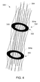
- the cable twist allowance system 300 includes a plurality of hoop portions 302 similar to the hoop portion 202 shown in FIGS. 3A and 3B
- the hoop portions 302 receive a plurality of cables 304 outside, along a periphery region 308 of the hoop portions 302 and inside a center region 310 thereof.
- the cables 304 are arranged to zigzag between the hoop portions 302.
- a cable 304a is disposed inside the center region 310 of one hoop portion 302 and then outside the other hoop portion 302 in a zigzag manner to prevent overcrowding and overtwisting of the cables 304.
- the present invention is not limited to any particular number of hoop portions 302 or cables 304 and may vary as needed.
- FIG. 5 is a graph illustrating zigzag displacement cable parameters for performing zigzag displacement of cabling as shown in FIG. 4 according to one or more embodiments of the present invention.
- the required twist allowance length of the cables 304 (as depicted in FIG. 4 ) is dependent upon the desired degree of turn or twist of each cable 304 and the length of the cable 304.
- the length of the cable 304 is 1.2 m (4 feet)
- approximately 1.5 cm (0.6 inches) will be the required twist allowance needed as indicated by line 502.
- the cable 304 is of a longer length to radius or degree of turn, then less required twist allowance length is needed for turning or twisting as indicated by line 504.
- the length of a helix (cable) can be estimated by the square root of the length squared plus the total circumference of the traversed in the twist. This works out to be approximately 7% additional length for 15 cm (6 inch) radius column spacing of 6 m (20 feet) having 2.5 revolutions of twist or a 23 cm (9 inch) displacement in a zigzag pattern repeated 5 times along the column.
- FIG. 6 is a flow diagram illustrating an exemplary method for performing cable twist allowance within the system shown in FIG. 2A , that can be implemented in an embodiment of the present invention.
- the method 600 will be described with reference to FIG. 2A .
- the method begins at operation 610 where cables 112 are received within a cable twist allowance system 100 housed within the tower of a wind turbine system.
- the cables 112 in cable sets are received within housing sections 110 of lever members 106 engaged with a periphery of a sun gear 102 of the cable twist allowance system 100.
- the process continues to operation 620 where when radial forces are applied to the cables 112, the position of the respective lever member 106 is adjusted via a corresponding lever compression member 116, based on the amount of tension applied.
- the adjustment of the position of the lever member 106 adjusts the outer diameter of the cable twist allowance system 100 within the tower.
- FIG. 7 is a flow diagram illustrating an exemplary method for performing cable twist allowance 200 within the system shown in FIG. 3A .
- the method 700 begins at operation 710, where cables 204 grouped into cable sets are inserted through openings 203 within an inner region and a periphery region of a hoop portion 202 of the cable twist allowance system 200, in an alternating zigzag arrangement. From operation 710, the process continues to operation 720, where the cables 204 are twisted and the hoop portion 202 is deformed, to adjust the position of the cable sets to a center region of the hoop portion 202.
- Embodiments of the present invention provide the advantages of preventing overcrowding and overtwisting of cables within a power system (e.g., a tower of a wind turbine system). Overcrowding and overtwisting is prevented by a rigid cable arrangement controlling axial tension on the system based on radial forces applied to the cables.
- a power system e.g., a tower of a wind turbine system.
Landscapes
- Engineering & Computer Science (AREA)
- Mechanical Engineering (AREA)
- Combustion & Propulsion (AREA)
- General Engineering & Computer Science (AREA)
- Life Sciences & Earth Sciences (AREA)
- Sustainable Development (AREA)
- Sustainable Energy (AREA)
- Chemical & Material Sciences (AREA)
- Civil Engineering (AREA)
- Architecture (AREA)
- Structural Engineering (AREA)
- Wind Motors (AREA)
- Bridges Or Land Bridges (AREA)
- Transmission Devices (AREA)
- Flexible Shafts (AREA)
Abstract
Description
- The present invention relates generally to cable twist allowance system for power systems. In particular, the present invention relates to a cable twist allowance system for power systems such as wind turbine systems.
- In a wind turbine system, the wind turbine converts kinetic energy in wind into mechanical energy to be supplied for use within a power grid. An example of a conventional wind turbine system is shown in
FIG. 1 . The system ofFIG. 1 includes awind turbine 2 with atower 4, for supporting anacelle 6 including various components for operating the system. Some of the components include adrive train 8 for driving thewind turbine 2. - A
hub 9 has a plurality ofrotatable blades 10 that form a rotor at an end of thedrive train 8. Theblades 10 rotate to drive agearbox 12 connected to anelectrical generator 14 and acontrol system 16. Thecontrol system 16 receives input from an anemometer (i.e., wind-speed monitor) 18 that measures wind speed and direction. A plurality ofcables 20 extend from theelectrical generator 14 to provide power to the grid. - The
control system 16 provides control signals for operation of thewind turbine 2. Ayaw drive 24 andyaw deck 26 provide yaw orientation for thewind turbine 2. The yaw orientation is controlled by thecontrol system 16, based on information received from theanemometer 18. - A conventional method for cabling in wind turbine systems involves hanging cables in a free-hanging loop for a suitable distance and then attaching the cables to the sidewall of the
tower 4 in a ribbon-type arrangement. The free-hanging loop allows for twisting of the cables as a result of the operation of theyaw drive 24. This method, however, can cause overtwisting and overcrowding of thecables 20 within thetower 4. This overtwisting and overcrowding results in overheating and abrasion of the cables leading to failure of the components within thenacelle 6. This failure creates interference in the supply of power through the tower and to the power grid. - Given the aforementioned deficiencies, a need exists for methods and systems that provide a cable twist allowance system that prevents overcrowding and overheating of cabling therein.
- In one exemplary embodiment, a cable twist allowance system for a wind turbine system is provided. The system includes a sun gear disposed within a tower of wind turbine, a pivot disk connected with the sun gear, a plurality of lever members, each including a plurality of cables and spaced a predetermined distance apart from each other, the plurality of lever members being pivotably connected with a surface of the pivot disk and rotatable about the sun gear; and a plurality of compression members, each compression member corresponding to each lever member and adjusting a position of a respective lever member based on a radial force applied to the plurality of cables of the respective lever member.
- In another exemplary embodiment, a cable twist allowance system for a wind turbine system is provided. The system includes a hoop portion housed within a tower of the wind turbine and comprising a plurality of openings; and a plurality of cables disposed in cable sets and being received within the openings. A number of the cable sets are disposed along an outer periphery region of the hoop portion and a remaining number of the cable sets are disposed along an inner surface of the hoop portion. When the plurality of cables are twisted due to radial force applied thereto, the hoop portion is deformed and a position of the cable sets is adjusted to be in a central region of the hoop portion.
- The foregoing has broadly outlined some of the aspects and features of various embodiments, which should be construed to be merely illustrative of various potential applications of the disclosure. Other beneficial results can be obtained by applying the disclosed information in a different manner or by combining various aspects of the disclosed embodiments. Accordingly, other aspects and a more comprehensive understanding may be obtained by referring to the detailed description of the exemplary embodiments taken in conjunction with the accompanying drawings, in addition to the scope defined by the claims.
-
-
FIG. 1 is a schematic side view of a conventional wind turbine system. -
FIG. 2A is a schematic top view of a cable twist allowance system that can be implemented within one or more embodiments of the present invention. -
FIG. 2B is an exploded view of a lever of the cable twist allowance system shown inFIG. 2A that can be implemented within one or more embodiments of the present invention. -
FIGS. 3A and 3B are schematic top views of a cable twist allowance system that can be implemented within one or more alternative embodiments of the present invention. -
FIG. 4 is a schematic view of the cable twist allowance system as shown inFIGS. 3A and 3B that can be implemented within one or more alternative embodiments of the present invention. -
FIG. 5 is a graph illustrating zigzag displacement cable parameters for performing zigzag displacement of cabling as shown inFIG. 4 according to one or more embodiments of the present invention. -
FIG. 6 is a flow diagram illustrating an exemplary method for performing cable twist allowance in the system shown inFIG. 2A , that can be implemented in an embodiment of the present invention. -
FIG. 7 is a flow diagram illustrating an exemplary method for performing cable twist allowance within the system shown inFIG. 3A , that can be implemented in an embodiment of the present invention. - The drawings are only for purposes of illustrating preferred embodiments and are not to be construed as limiting the disclosure. Given the following enabling description of the drawings, the novel aspects of the present disclosure should become evident to a person of ordinary skill in the art. This detailed description uses numerical and letter designations to refer to features in the drawings. Like or similar designations in the drawings and description have been used to refer to like or similar parts of embodiments of the invention.
- As required, detailed embodiments are disclosed herein. It must be understood that the disclosed embodiments are merely exemplary of various and alternative forms. As used herein, the word "exemplary" is used expansively to refer to embodiments that serve as illustrations, specimens, models, or patterns. The figures are not necessarily to scale and some features may be exaggerated or minimized to show details of particular components. In other instances, well-known components, systems, materials, or methods that are known to those having ordinary skill in the art have not been described in detail in order to avoid obscuring the present disclosure. Therefore, specific structural and functional details disclosed herein are not to be interpreted as limiting, but merely as a basis for the claims and as a representative basis for teaching one skilled in the art.
- Exemplary embodiments of the present invention provides a cable twist allowance system that can be implemented within a power system such as a wind turbine system to prevent overtwisting and overcrowding of the cables within the tower thereof. The present invention is not limited to being used in a wind turbine system and may therefore be implemented within any type of power system or other system including a cable arrangement for supplying power therein.
- The present invention provides a cable twist allowance system which controls axial tension in the surface of the column of cables in the tower of the wind turbine system through the radial forces on the individual sets of cables.
-
FIG. 2A is a schematic top view of a cabletwist allowance system 100 that can be implemented within one or more embodiments of the present invention.FIG. 2B is an exploded view of a lever of the cable twist allowance system shown inFIG. 2A that can be implemented within one or more embodiments of the present invention. Details regarding the cable twist allowance system according to one or more embodiments of the present invention will now be discussed below with reference toFIGS. 2A and 2B . - As shown, the cable
twist allowance system 100 includes asun gear 102 and apivot disk 103 connected together. Thepivot disk 103 can rotate relative to thesun gear 102. Thesun gear 102 is formed of a diameter ranging from approximately 1.27 m (50 inches) to 15.24 m (50 feet) for example. Thesun gear 102 is positioned within the tower of the wind turbine system. Thesun gear 102 may be formed of a material including metal and hard plastic, for example. Asingle sun gear 102, or a plurality of sun gears, may be provided within the tower for supporting the cabling therein. The present invention is not limited to a particular number of sun gears 102. - The
sun gear 102 includes a plurality of teeth (or gears) 104 along a periphery region thereof for mating. - The cable
twist allowance system 100 further includes a plurality oflever members 106 to be circumferentially spaced apart a predetermined distance from each other along a surface of thepivot disk 103. As shown inFIG. 2B , thelever members 106 each include anopening 105 for pivotably connecting with a surface of thepivot disk 103 and a plurality of teeth (or gears) 108 at one end thereof for engaging with the corresponding teeth (or gears) 104 of thesun gear 102. Thelever members 106 are pivotably engaged with thesun gear 102 via the teeth (or gears) 108. Eachlever member 106 further includes ahousing section 110 at an opposite end thereof along aperiphery region 111 of thelever member 106 forhousing cables 112 therein. - The
housing section 110 is formed by awire restraint portion 114 creating a space within thelever member 106 for receiving thecables 112. Thewire restraint portion 114 is configured to restrain thecables 110. As shown, thecables 112 include three separate cables representing three-phase AC power system formed in cable sets. However, the present invention is not limited to a three-phase power system. Thecables 112 may include low-voltage (up to 105 °C) power cables, medium-voltage (approximately 180 °C) power cables, for example. However, the present invention is not limited. - The cable
twist allowance system 100 further comprises alever compression member 116 configured to connect alever member 106 to anadjacent lever member 106 as shown inFIG. 2A . Thelever compression member 116 may be a spring or any type of compression mechanism suitable for the purposes set forth herein. - The
lever compression member 116 adjusts a position of thelever member 106 and controls axial tension on thesystem 100, when radial forces are applied to thecables 112. A singlelever compression member 116 is shown inFIG. 2A for illustration purposes only. The cabletwist allowance system 100 comprises a plurality oflever compression members 116 to connect eachlever member 106 to anadjacent lever member 106 along the periphery of thesun gear 102. That is, in the embodiment of the present invention, a correspondinglever compression member 116 is provided for eachlever member 106. Eachlever compression member 116 is connected to therespective lever member 106 at a midpoint and to the adjacent lever member at a radially inner point, i.e., near to the end with the teeth (or gears) 108 as shown inFIG. 2A . - The position of each
lever member 106 may range from Position A, Position B, and Position C as shown inFIG. 2A , depending on the amount of tension applied. Thelever compression member 116 controls the position of therespective lever member 106 based on the tension applied thereto. For example, if a nominal amount of tension is applied, e.g., only the weight of thelever member 106, the position of therespective lever member 106 is Position 'A'. Thus, thelever compression member 116 dominates the position of thelever member 106. - If minimal tension is applied, the position of the
respective lever member 106 is adjusted to Position 'B' as shown. On the other hand, if a large amount of tension is applied, the position of therespective lever member 106 is adjusted to Position C. Thelever compression member 116 attempts to maintain therespective lever member 106 in the Position 'A' but the position may be adjusted based on the force on thecables 112. Thus, the outer diameter of the cabletwist allowance system 100 may vary dependent upon the force being applied to thecables 112. In particular, the outer diameter of the cabletwist allowance system 100 may decrease as the force applied to thecables 112 increases and thelever members 106 move from Position A towards Position C against the bias applied by thelever compression members 116. - The range of the lever member motion combines the twist of the
cables 112 and the radius expansion and compression (i.e., the diameter) of the cabletwist allowance system 100. - According to another embodiment of the present invention, the cable
twist allowance system 100 may comprise a plurality of tension/compression members 120 instead of thelever compression members 116. The tension/compression members 120 are disposed alongcentral area surface 125 of thesun gear 102. The tension/compression members 120 may be arranged to correspond to, and be in connection with, one ormore lever members 106. The tension/compression members 120 are configured to adjust the position of thelever members 106 based upon the radial forces applied to thecables 112. - In this embodiment, the
sun gear 102 is used to duplicate the lever position for a total of thelever members 106 to correspond to each other. In other words, relative rotation between thesun gear 102 and thepivot disk 103 can ensure that thelever members 106 have substantially the same position because of the engagement between the respective teeth (or gears) 104, 108. -
FIGS. 3A and 3B are schematic top views of a cable twist allowance system that can be implemented within one or more alternative embodiments of the present invention. As shown inFIG. 3A , the cabletwist allowance system 200 includes ahoop portion 202 includingopenings 203 for receiving a plurality ofcables 204 formed incable sets 206 therethrough. Thecables 204 are untwisted and thehoop portion 202 is relaxed such that some of the cable sets 206 are disposed along anouter periphery region 208 of thehoop portion 202. - The remainder of the cable sets 206 are disposed along an
inner surface 210 of thehoop portion 202. Thehoop portion 202 is formed of an elastic material such as rubber, or some other type of flexible material suitable for the purposes set forth herein. As shown inFIG. 3B , when thecables 204 are twisted due to tension increased within the wind turbine system, thehoop portion 202 is deformed and the position of the cable sets 206 are adjusted to be in acenter region 212 of thehoop portion 202. -
FIG. 4 is a schematic view of the cable twist allowance system as shown inFIGS. 3A and 3B that can be implemented within one or more alternative embodiments of the present invention. As shown inFIG. 4 , the cabletwist allowance system 300 is provided. The cabletwist allowance system 300 includes an alternating cable zigzag type arrangement to minimize overtwisting and overcrowding of cables within the tower of the wind turbine system. - The cable
twist allowance system 300 includes a plurality ofhoop portions 302 similar to thehoop portion 202 shown inFIGS. 3A and 3B Thehoop portions 302 receive a plurality ofcables 304 outside, along aperiphery region 308 of thehoop portions 302 and inside acenter region 310 thereof. Thecables 304 are arranged to zigzag between thehoop portions 302. For example, acable 304a is disposed inside thecenter region 310 of onehoop portion 302 and then outside theother hoop portion 302 in a zigzag manner to prevent overcrowding and overtwisting of thecables 304. The present invention is not limited to any particular number ofhoop portions 302 orcables 304 and may vary as needed. -
FIG. 5 is a graph illustrating zigzag displacement cable parameters for performing zigzag displacement of cabling as shown inFIG. 4 according to one or more embodiments of the present invention. As shown in thegraph 500, the required twist allowance length of the cables 304 (as depicted inFIG. 4 ) is dependent upon the desired degree of turn or twist of eachcable 304 and the length of thecable 304. - For example, if the desired degree of turn or twist is 50 degrees, and the length of the
cable 304 is 1.2 m (4 feet), approximately 1.5 cm (0.6 inches) will be the required twist allowance needed as indicated byline 502. If thecable 304 is of a longer length to radius or degree of turn, then less required twist allowance length is needed for turning or twisting as indicated byline 504. The length of a helix (cable) can be estimated by the square root of the length squared plus the total circumference of the traversed in the twist. This works out to be approximately 7% additional length for 15 cm (6 inch) radius column spacing of 6 m (20 feet) having 2.5 revolutions of twist or a 23 cm (9 inch) displacement in a zigzag pattern repeated 5 times along the column. -
FIG. 6 is a flow diagram illustrating an exemplary method for performing cable twist allowance within the system shown inFIG. 2A , that can be implemented in an embodiment of the present invention. Themethod 600 will be described with reference toFIG. 2A . The method begins atoperation 610 wherecables 112 are received within a cabletwist allowance system 100 housed within the tower of a wind turbine system. Thecables 112 in cable sets are received withinhousing sections 110 oflever members 106 engaged with a periphery of asun gear 102 of the cabletwist allowance system 100. - From
operation 610, the process continues tooperation 620 where when radial forces are applied to thecables 112, the position of therespective lever member 106 is adjusted via a correspondinglever compression member 116, based on the amount of tension applied. The adjustment of the position of thelever member 106 adjusts the outer diameter of the cabletwist allowance system 100 within the tower. -
FIG. 7 is a flow diagram illustrating an exemplary method for performingcable twist allowance 200 within the system shown inFIG. 3A . Themethod 700 begins atoperation 710, wherecables 204 grouped into cable sets are inserted throughopenings 203 within an inner region and a periphery region of ahoop portion 202 of the cabletwist allowance system 200, in an alternating zigzag arrangement. Fromoperation 710, the process continues tooperation 720, where thecables 204 are twisted and thehoop portion 202 is deformed, to adjust the position of the cable sets to a center region of thehoop portion 202. - Embodiments of the present invention provide the advantages of preventing overcrowding and overtwisting of cables within a power system (e.g., a tower of a wind turbine system). Overcrowding and overtwisting is prevented by a rigid cable arrangement controlling axial tension on the system based on radial forces applied to the cables.
- This written description uses examples to disclose the invention, including the best mode, and also to enable any person skilled in the art to practice the invention including making and using any devices or systems and performing any incorporated methods. The patentable scope of the invention is defined by the claims, and may include other examples that occur to those skilled in the art. Such other examples are intended to be within the scope of the claims if they have structural elements that do not differ from the literal language of the claims, or if they include equivalent structural elements with insubstantial differences from the literal languages of the claims.
Claims (15)
- A cable twist allowance system (100) for a wind turbine, comprising:a sun gear (102);a pivot disk (103) connected with the sun gear (102);a plurality of lever members (106), each including a plurality of cables (112) and spaced a predetermined distance apart from each other, the plurality of lever members (106) being pivotably connected with a surface of the pivot disk (103) and rotatable about the sun gear (102); anda plurality of compression members (116; 120), each corresponding to a lever member (106) and adjusting a position thereof based on a radial force applied to the plurality of cables (112) of the respective lever member (106).
- A cable twist allowance system (100) according to claim 1, wherein the sun gear (102) comprises a plurality of teeth (104) at a periphery thereof and each lever member (106) comprises a plurality of teeth (108) corresponding to and engaging with the plurality of teeth (104) of the sun gear (102).
- A cable twist allowance system (100) according to claim 1, wherein each compression member, optionally a spring member, connects a respective one of the lever members (106) to an adjacent lever member (106).
- A cable twist allowance system (100) according to any preceding claim, wherein each lever member (106) includes a housing section (110) for housing cables (112) therein, the housing section (110) optionally being formed by a wire restraint portion (114) configured to restrain the cables (112) within the housing section (110).
- A cable twist allowance system (100) according to any preceding claim, wherein the compression members (120) are disposed along a central area surface (125) of the sun gear (102) and are arranged to correspond to and in connection with one or more lever members (106).
- A method for performing cable twist allowance within a wind turbine system, the method comprising:receiving cable sets including a plurality of cables (112) within housing sections (110) of lever members (106) engaged with a sun gear (102) within a cable twist allowance system (100) housed within a tower of the wind turbine system; andadjusting a position of a lever member (106) based on a radial force applied to the plurality of cables (112) within a cable set of the lever member (106).
- A method according to claim 6, wherein the lever members (106) are pivotably connected with a pivot disk (103) connected to the sun gear (102), and rotatable about the sun gear (102).
- A method according to claim 6 or claim 7, wherein the position of the lever member (106) is adjusted using a compression member (116), optionally a spring member, attaching the lever member (106) to an adjacent lever member (106).
- A method according to any of claims 6 to 8, wherein adjusting the position of the lever member (106) adjusts a diameter of the cable twist allowance system (100).
- A cable twist allowance system (200) for a wind turbine system, comprising:a hoop portion (202) comprising a plurality of openings (203); anda plurality of cables (204) disposed in cable sets (206) and received within the openings (203);wherein a first proportion of the cable sets (206) are disposed in openings (203) at an outer periphery region (208) of the hoop portion (202) and a second proportion of the cable sets (206) are disposed in openings (203) at an inner periphery region (210) of the hoop portion (202) such that when the plurality of cables (204) are twisted due to radial force applied thereto, the hoop portion (202) is deformed and a position of the cable sets (206) is adjusted to be in a central region (212) of the hoop portion (202).
- A method of performing cable twist allowance within a wind turbine system, the method comprising:arranging cable sets (206) or cables (304) in a column; andwhen a radial force is applied, adjusting a position of each cable set (206) or cable (304) to adjust a diameter of the column, via adjusting and tensioning means.
- A method according to claim 11, wherein a hoop portion (202) comprises a plurality of openings (203) for receiving the cable sets (206), the method further comprising;
disposing a first proportion of the cable sets (206) at an outer periphery region (208) of the hoop portion (202) and a second proportion of the cable sets (206) at an inner periphery region (210) of the hoop portion (202); and
deforming the hoop portion (202) and adjusting a position of the cable sets (206) to be in a center region (212) of the hoop portion (202), when cables are twisted due to radial force being applied thereto. - A method according to claim 11 or claim 12, further comprising:arranging the cable sets (206) in an alternating zigzag arrangement.
- A method according to claim 11, wherein a plurality of hoop portions (302) comprise an opening in a center region (310), the method further comprising:disposing a plurality of cables (304) inside the center region (310) of one hoop portion (302), and outside along a periphery region of another hoop portion (302), wherein the plurality of cables (302) are disposed in an alternating zigzag arrangement.
- A method according to claim 14, wherein a twist length allowance of each cable (304) is dependent upon a desired degree of twist of the cable and a length of the cable.
Applications Claiming Priority (1)
| Application Number | Priority Date | Filing Date | Title |
|---|---|---|---|
| US14/715,983 US9831653B2 (en) | 2015-05-19 | 2015-05-19 | Cable twist allowance system for power system |
Publications (3)
| Publication Number | Publication Date |
|---|---|
| EP3096009A2 true EP3096009A2 (en) | 2016-11-23 |
| EP3096009A3 EP3096009A3 (en) | 2017-04-12 |
| EP3096009B1 EP3096009B1 (en) | 2019-09-18 |
Family
ID=55969060
Family Applications (1)
| Application Number | Title | Priority Date | Filing Date |
|---|---|---|---|
| EP16169758.6A Active EP3096009B1 (en) | 2015-05-19 | 2016-05-16 | Cable twist allowance system for power system |
Country Status (5)
| Country | Link |
|---|---|
| US (1) | US9831653B2 (en) |
| EP (1) | EP3096009B1 (en) |
| CN (1) | CN106168197B (en) |
| BR (1) | BR102016010258A2 (en) |
| CA (1) | CA2929755A1 (en) |
Cited By (2)
| Publication number | Priority date | Publication date | Assignee | Title |
|---|---|---|---|---|
| CN108757352A (en) * | 2018-05-22 | 2018-11-06 | 江苏金风科技有限公司 | Cable protecting device and wind power generating set |
| CN109038440A (en) * | 2018-08-15 | 2018-12-18 | 山东大学 | A kind of half active anti-dance damping control device |
Families Citing this family (3)
| Publication number | Priority date | Publication date | Assignee | Title |
|---|---|---|---|---|
| CN113541078A (en) * | 2021-07-27 | 2021-10-22 | 龚云 | Be applied to overhead line's electric power fitting |
| CN113746041B (en) * | 2021-09-26 | 2025-07-22 | 中船海装风电有限公司 | Wind generating set and cable twisting protection system thereof |
| CN120566343B (en) * | 2025-07-30 | 2025-10-14 | 沈阳国联电缆附件制造有限公司 | Ultra-high voltage lead seal monitoring cable terminal |
Family Cites Families (15)
| Publication number | Priority date | Publication date | Assignee | Title |
|---|---|---|---|---|
| US4545728A (en) | 1983-08-30 | 1985-10-08 | Cheney Jr Marvin C | Wind turbine generator with improved operating subassemblies |
| JP2005137097A (en) * | 2003-10-29 | 2005-05-26 | Ryokeiso Kk | Device and method for installing cable |
| JP2008298051A (en) | 2007-06-04 | 2008-12-11 | Ebara Corp | Wind power generator device |
| DE102009013728A1 (en) * | 2009-03-20 | 2010-09-30 | Repower Systems Ag | Wind turbine with twistable nacelle cable guide |
| US8058740B2 (en) | 2009-12-10 | 2011-11-15 | General Electric Company | Wind turbine cable twist prevention |
| ES2601779T3 (en) | 2010-06-03 | 2017-02-16 | Ae Rotor Holding B.V. | Tower for a wind turbine |
| DK177337B1 (en) | 2011-10-26 | 2013-01-21 | Envision Energy Denmark Aps | Wind Turbine Including a Cable Loop |
| US8366396B2 (en) | 2011-11-28 | 2013-02-05 | General Electric Company | Unit for cable management and wind turbine |
| CN202483807U (en) * | 2012-03-01 | 2012-10-10 | 国电联合动力技术有限公司 | Twisting cable fixing and separating structure of wind turbine tower |
| CN202545130U (en) | 2012-04-06 | 2012-11-21 | 中船重工(重庆)海装风电设备有限公司 | A tower cable torsion support ring |
| CN202746120U (en) | 2012-08-07 | 2013-02-20 | 上海万德风力发电股份有限公司 | Cable loosening system used in wind generating set |
| KR102078997B1 (en) * | 2012-10-04 | 2020-02-19 | 하이닥 악세서리즈 게엠베하 | Apparatus for rooting cables in wind turbines |
| DK201270766A (en) * | 2012-12-06 | 2014-06-06 | Envision Energy Denmark Aps | System for twisting cables in a wind turbine tower |
| DK177637B1 (en) * | 2013-03-25 | 2014-01-13 | Envision Energy Denmark Aps | Unit for rotating cable spacing plates in a wind turbine tower |
| CN103758709A (en) | 2013-04-07 | 2014-04-30 | 邓世平 | Wind generator |
-
2015
- 2015-05-19 US US14/715,983 patent/US9831653B2/en not_active Expired - Fee Related
-
2016
- 2016-05-12 CA CA2929755A patent/CA2929755A1/en not_active Abandoned
- 2016-05-16 EP EP16169758.6A patent/EP3096009B1/en active Active
- 2016-05-17 BR BR102016010258A patent/BR102016010258A2/en not_active Application Discontinuation
- 2016-05-19 CN CN201610333636.7A patent/CN106168197B/en not_active Expired - Fee Related
Non-Patent Citations (1)
| Title |
|---|
| None |
Cited By (5)
| Publication number | Priority date | Publication date | Assignee | Title |
|---|---|---|---|---|
| CN108757352A (en) * | 2018-05-22 | 2018-11-06 | 江苏金风科技有限公司 | Cable protecting device and wind power generating set |
| CN108757352B (en) * | 2018-05-22 | 2019-10-15 | 江苏金风科技有限公司 | Cable protection devices and wind turbines |
| US11460007B2 (en) | 2018-05-22 | 2022-10-04 | Jiangsu Goldwind Science & Technology Co., Ltd. | Cable protection device and wind generator set |
| CN109038440A (en) * | 2018-08-15 | 2018-12-18 | 山东大学 | A kind of half active anti-dance damping control device |
| CN109038440B (en) * | 2018-08-15 | 2019-04-16 | 山东大学 | A kind of half active anti-dance damping control device |
Also Published As
| Publication number | Publication date |
|---|---|
| EP3096009B1 (en) | 2019-09-18 |
| EP3096009A3 (en) | 2017-04-12 |
| US9831653B2 (en) | 2017-11-28 |
| CN106168197B (en) | 2019-12-24 |
| CA2929755A1 (en) | 2016-11-19 |
| US20160341181A1 (en) | 2016-11-24 |
| BR102016010258A2 (en) | 2016-11-22 |
| CN106168197A (en) | 2016-11-30 |
Similar Documents
| Publication | Publication Date | Title |
|---|---|---|
| EP3096009B1 (en) | Cable twist allowance system for power system | |
| CN101943117B (en) | Method and apparatus for controlling the tip speed of a blade of a wind turbine | |
| EP2273105B1 (en) | Method and system for noise controlled operation of a wind turbine | |
| US7775760B1 (en) | Turbine wheel | |
| KR20110010241A (en) | Wind power generator that implements multi-cycloidal curve system with eccentric shaft | |
| WO2011084154A1 (en) | Vertical axis variable geometry wind energy collection system | |
| EP2957767B1 (en) | Methods and systems to operate a wind turbine | |
| US9261074B2 (en) | Variable bolt parameters for a wind turbine rotor blade | |
| US10018189B1 (en) | Wind turbine tower cable positioning device | |
| KR102471788B1 (en) | rotor for electric generator | |
| US20120286518A1 (en) | Maritime Current Power Plant Park and a Method for Its Production | |
| CA2787022C (en) | Method and apparatus for fluid turbine having a linear actuator | |
| EP3587804B1 (en) | Wind turbine power generation facility and maintenance method therefore | |
| KR102009596B1 (en) | Multi type wind turbine and control mehtod of the same | |
| JP5619123B2 (en) | Windmill and wind power generator | |
| KR101273648B1 (en) | Tidal power generator | |
| JP2015166562A (en) | Vertical axis drag type wind turbine capable of preventing its overspeed under strong wind and wind power generator | |
| KR101061315B1 (en) | Wind generator that varies air resistance according to wind speed | |
| KR101411475B1 (en) | Wind power generator and method for adjusting pitch angle of blade | |
| KR20110080946A (en) | Wind power generator | |
| US12504002B1 (en) | Tension turbine assembly and operational control system | |
| KR101630111B1 (en) | Blade angle control system of wind power generator | |
| ITBA20110022A1 (en) | WIND GENERATOR WITH VELICA VARIABLE SURFACE ROTOR AUTOMATICALLY ACCORDING TO WIND INTENSITY. | |
| KR20130068041A (en) | Apparatus for controlling pitch of blade | |
| JP6613733B2 (en) | Wind power generator |
Legal Events
| Date | Code | Title | Description |
|---|---|---|---|
| PUAI | Public reference made under article 153(3) epc to a published international application that has entered the european phase |
Free format text: ORIGINAL CODE: 0009012 |
|
| AK | Designated contracting states |
Kind code of ref document: A2 Designated state(s): AL AT BE BG CH CY CZ DE DK EE ES FI FR GB GR HR HU IE IS IT LI LT LU LV MC MK MT NL NO PL PT RO RS SE SI SK SM TR |
|
| AX | Request for extension of the european patent |
Extension state: BA ME |
|
| PUAL | Search report despatched |
Free format text: ORIGINAL CODE: 0009013 |
|
| AK | Designated contracting states |
Kind code of ref document: A3 Designated state(s): AL AT BE BG CH CY CZ DE DK EE ES FI FR GB GR HR HU IE IS IT LI LT LU LV MC MK MT NL NO PL PT RO RS SE SI SK SM TR |
|
| AX | Request for extension of the european patent |
Extension state: BA ME |
|
| RIC1 | Information provided on ipc code assigned before grant |
Ipc: F03D 80/80 20160101AFI20170308BHEP Ipc: H02G 3/32 20060101ALI20170308BHEP |
|
| STAA | Information on the status of an ep patent application or granted ep patent |
Free format text: STATUS: REQUEST FOR EXAMINATION WAS MADE |
|
| 17P | Request for examination filed |
Effective date: 20171002 |
|
| RBV | Designated contracting states (corrected) |
Designated state(s): AL AT BE BG CH CY CZ DE DK EE ES FI FR GB GR HR HU IE IS IT LI LT LU LV MC MK MT NL NO PL PT RO RS SE SI SK SM TR |
|
| GRAP | Despatch of communication of intention to grant a patent |
Free format text: ORIGINAL CODE: EPIDOSNIGR1 |
|
| STAA | Information on the status of an ep patent application or granted ep patent |
Free format text: STATUS: GRANT OF PATENT IS INTENDED |
|
| INTG | Intention to grant announced |
Effective date: 20190516 |
|
| GRAS | Grant fee paid |
Free format text: ORIGINAL CODE: EPIDOSNIGR3 |
|
| GRAA | (expected) grant |
Free format text: ORIGINAL CODE: 0009210 |
|
| STAA | Information on the status of an ep patent application or granted ep patent |
Free format text: STATUS: THE PATENT HAS BEEN GRANTED |
|
| AK | Designated contracting states |
Kind code of ref document: B1 Designated state(s): AL AT BE BG CH CY CZ DE DK EE ES FI FR GB GR HR HU IE IS IT LI LT LU LV MC MK MT NL NO PL PT RO RS SE SI SK SM TR |
|
| REG | Reference to a national code |
Ref country code: GB Ref legal event code: FG4D |
|
| REG | Reference to a national code |
Ref country code: CH Ref legal event code: EP |
|
| REG | Reference to a national code |
Ref country code: DE Ref legal event code: R096 Ref document number: 602016020698 Country of ref document: DE |
|
| REG | Reference to a national code |
Ref country code: AT Ref legal event code: REF Ref document number: 1181617 Country of ref document: AT Kind code of ref document: T Effective date: 20191015 |
|
| REG | Reference to a national code |
Ref country code: IE Ref legal event code: FG4D |
|
| REG | Reference to a national code |
Ref country code: NL Ref legal event code: MP Effective date: 20190918 |
|
| PG25 | Lapsed in a contracting state [announced via postgrant information from national office to epo] |
Ref country code: LT Free format text: LAPSE BECAUSE OF FAILURE TO SUBMIT A TRANSLATION OF THE DESCRIPTION OR TO PAY THE FEE WITHIN THE PRESCRIBED TIME-LIMIT Effective date: 20190918 Ref country code: HR Free format text: LAPSE BECAUSE OF FAILURE TO SUBMIT A TRANSLATION OF THE DESCRIPTION OR TO PAY THE FEE WITHIN THE PRESCRIBED TIME-LIMIT Effective date: 20190918 Ref country code: SE Free format text: LAPSE BECAUSE OF FAILURE TO SUBMIT A TRANSLATION OF THE DESCRIPTION OR TO PAY THE FEE WITHIN THE PRESCRIBED TIME-LIMIT Effective date: 20190918 Ref country code: BG Free format text: LAPSE BECAUSE OF FAILURE TO SUBMIT A TRANSLATION OF THE DESCRIPTION OR TO PAY THE FEE WITHIN THE PRESCRIBED TIME-LIMIT Effective date: 20191218 Ref country code: NO Free format text: LAPSE BECAUSE OF FAILURE TO SUBMIT A TRANSLATION OF THE DESCRIPTION OR TO PAY THE FEE WITHIN THE PRESCRIBED TIME-LIMIT Effective date: 20191218 Ref country code: FI Free format text: LAPSE BECAUSE OF FAILURE TO SUBMIT A TRANSLATION OF THE DESCRIPTION OR TO PAY THE FEE WITHIN THE PRESCRIBED TIME-LIMIT Effective date: 20190918 |
|
| REG | Reference to a national code |
Ref country code: LT Ref legal event code: MG4D |
|
| PG25 | Lapsed in a contracting state [announced via postgrant information from national office to epo] |
Ref country code: RS Free format text: LAPSE BECAUSE OF FAILURE TO SUBMIT A TRANSLATION OF THE DESCRIPTION OR TO PAY THE FEE WITHIN THE PRESCRIBED TIME-LIMIT Effective date: 20190918 Ref country code: GR Free format text: LAPSE BECAUSE OF FAILURE TO SUBMIT A TRANSLATION OF THE DESCRIPTION OR TO PAY THE FEE WITHIN THE PRESCRIBED TIME-LIMIT Effective date: 20191219 Ref country code: LV Free format text: LAPSE BECAUSE OF FAILURE TO SUBMIT A TRANSLATION OF THE DESCRIPTION OR TO PAY THE FEE WITHIN THE PRESCRIBED TIME-LIMIT Effective date: 20190918 Ref country code: AL Free format text: LAPSE BECAUSE OF FAILURE TO SUBMIT A TRANSLATION OF THE DESCRIPTION OR TO PAY THE FEE WITHIN THE PRESCRIBED TIME-LIMIT Effective date: 20190918 |
|
| REG | Reference to a national code |
Ref country code: AT Ref legal event code: MK05 Ref document number: 1181617 Country of ref document: AT Kind code of ref document: T Effective date: 20190918 |
|
| PG25 | Lapsed in a contracting state [announced via postgrant information from national office to epo] |
Ref country code: AT Free format text: LAPSE BECAUSE OF FAILURE TO SUBMIT A TRANSLATION OF THE DESCRIPTION OR TO PAY THE FEE WITHIN THE PRESCRIBED TIME-LIMIT Effective date: 20190918 Ref country code: NL Free format text: LAPSE BECAUSE OF FAILURE TO SUBMIT A TRANSLATION OF THE DESCRIPTION OR TO PAY THE FEE WITHIN THE PRESCRIBED TIME-LIMIT Effective date: 20190918 Ref country code: PT Free format text: LAPSE BECAUSE OF FAILURE TO SUBMIT A TRANSLATION OF THE DESCRIPTION OR TO PAY THE FEE WITHIN THE PRESCRIBED TIME-LIMIT Effective date: 20200120 Ref country code: ES Free format text: LAPSE BECAUSE OF FAILURE TO SUBMIT A TRANSLATION OF THE DESCRIPTION OR TO PAY THE FEE WITHIN THE PRESCRIBED TIME-LIMIT Effective date: 20190918 Ref country code: EE Free format text: LAPSE BECAUSE OF FAILURE TO SUBMIT A TRANSLATION OF THE DESCRIPTION OR TO PAY THE FEE WITHIN THE PRESCRIBED TIME-LIMIT Effective date: 20190918 Ref country code: IT Free format text: LAPSE BECAUSE OF FAILURE TO SUBMIT A TRANSLATION OF THE DESCRIPTION OR TO PAY THE FEE WITHIN THE PRESCRIBED TIME-LIMIT Effective date: 20190918 Ref country code: RO Free format text: LAPSE BECAUSE OF FAILURE TO SUBMIT A TRANSLATION OF THE DESCRIPTION OR TO PAY THE FEE WITHIN THE PRESCRIBED TIME-LIMIT Effective date: 20190918 Ref country code: PL Free format text: LAPSE BECAUSE OF FAILURE TO SUBMIT A TRANSLATION OF THE DESCRIPTION OR TO PAY THE FEE WITHIN THE PRESCRIBED TIME-LIMIT Effective date: 20190918 |
|
| PG25 | Lapsed in a contracting state [announced via postgrant information from national office to epo] |
Ref country code: SM Free format text: LAPSE BECAUSE OF FAILURE TO SUBMIT A TRANSLATION OF THE DESCRIPTION OR TO PAY THE FEE WITHIN THE PRESCRIBED TIME-LIMIT Effective date: 20190918 Ref country code: SK Free format text: LAPSE BECAUSE OF FAILURE TO SUBMIT A TRANSLATION OF THE DESCRIPTION OR TO PAY THE FEE WITHIN THE PRESCRIBED TIME-LIMIT Effective date: 20190918 Ref country code: IS Free format text: LAPSE BECAUSE OF FAILURE TO SUBMIT A TRANSLATION OF THE DESCRIPTION OR TO PAY THE FEE WITHIN THE PRESCRIBED TIME-LIMIT Effective date: 20200224 Ref country code: CZ Free format text: LAPSE BECAUSE OF FAILURE TO SUBMIT A TRANSLATION OF THE DESCRIPTION OR TO PAY THE FEE WITHIN THE PRESCRIBED TIME-LIMIT Effective date: 20190918 |
|
| REG | Reference to a national code |
Ref country code: DE Ref legal event code: R097 Ref document number: 602016020698 Country of ref document: DE |
|
| PLBE | No opposition filed within time limit |
Free format text: ORIGINAL CODE: 0009261 |
|
| STAA | Information on the status of an ep patent application or granted ep patent |
Free format text: STATUS: NO OPPOSITION FILED WITHIN TIME LIMIT |
|
| PG2D | Information on lapse in contracting state deleted |
Ref country code: IS |
|
| PG25 | Lapsed in a contracting state [announced via postgrant information from national office to epo] |
Ref country code: DK Free format text: LAPSE BECAUSE OF FAILURE TO SUBMIT A TRANSLATION OF THE DESCRIPTION OR TO PAY THE FEE WITHIN THE PRESCRIBED TIME-LIMIT Effective date: 20190918 Ref country code: IS Free format text: LAPSE BECAUSE OF FAILURE TO SUBMIT A TRANSLATION OF THE DESCRIPTION OR TO PAY THE FEE WITHIN THE PRESCRIBED TIME-LIMIT Effective date: 20200119 |
|
| PGFP | Annual fee paid to national office [announced via postgrant information from national office to epo] |
Ref country code: DE Payment date: 20200421 Year of fee payment: 5 Ref country code: FR Payment date: 20200422 Year of fee payment: 5 |
|
| 26N | No opposition filed |
Effective date: 20200619 |
|
| PG25 | Lapsed in a contracting state [announced via postgrant information from national office to epo] |
Ref country code: SI Free format text: LAPSE BECAUSE OF FAILURE TO SUBMIT A TRANSLATION OF THE DESCRIPTION OR TO PAY THE FEE WITHIN THE PRESCRIBED TIME-LIMIT Effective date: 20190918 |
|
| PGFP | Annual fee paid to national office [announced via postgrant information from national office to epo] |
Ref country code: GB Payment date: 20200423 Year of fee payment: 5 |
|
| PG25 | Lapsed in a contracting state [announced via postgrant information from national office to epo] |
Ref country code: CH Free format text: LAPSE BECAUSE OF NON-PAYMENT OF DUE FEES Effective date: 20200531 Ref country code: LI Free format text: LAPSE BECAUSE OF NON-PAYMENT OF DUE FEES Effective date: 20200531 Ref country code: MC Free format text: LAPSE BECAUSE OF FAILURE TO SUBMIT A TRANSLATION OF THE DESCRIPTION OR TO PAY THE FEE WITHIN THE PRESCRIBED TIME-LIMIT Effective date: 20190918 |
|
| REG | Reference to a national code |
Ref country code: BE Ref legal event code: MM Effective date: 20200531 |
|
| PG25 | Lapsed in a contracting state [announced via postgrant information from national office to epo] |
Ref country code: LU Free format text: LAPSE BECAUSE OF NON-PAYMENT OF DUE FEES Effective date: 20200516 |
|
| PG25 | Lapsed in a contracting state [announced via postgrant information from national office to epo] |
Ref country code: IE Free format text: LAPSE BECAUSE OF NON-PAYMENT OF DUE FEES Effective date: 20200516 |
|
| PG25 | Lapsed in a contracting state [announced via postgrant information from national office to epo] |
Ref country code: BE Free format text: LAPSE BECAUSE OF NON-PAYMENT OF DUE FEES Effective date: 20200531 |
|
| REG | Reference to a national code |
Ref country code: DE Ref legal event code: R119 Ref document number: 602016020698 Country of ref document: DE |
|
| GBPC | Gb: european patent ceased through non-payment of renewal fee |
Effective date: 20210516 |
|
| PG25 | Lapsed in a contracting state [announced via postgrant information from national office to epo] |
Ref country code: GB Free format text: LAPSE BECAUSE OF NON-PAYMENT OF DUE FEES Effective date: 20210516 Ref country code: DE Free format text: LAPSE BECAUSE OF NON-PAYMENT OF DUE FEES Effective date: 20211201 |
|
| PG25 | Lapsed in a contracting state [announced via postgrant information from national office to epo] |
Ref country code: TR Free format text: LAPSE BECAUSE OF FAILURE TO SUBMIT A TRANSLATION OF THE DESCRIPTION OR TO PAY THE FEE WITHIN THE PRESCRIBED TIME-LIMIT Effective date: 20190918 Ref country code: MT Free format text: LAPSE BECAUSE OF FAILURE TO SUBMIT A TRANSLATION OF THE DESCRIPTION OR TO PAY THE FEE WITHIN THE PRESCRIBED TIME-LIMIT Effective date: 20190918 Ref country code: FR Free format text: LAPSE BECAUSE OF NON-PAYMENT OF DUE FEES Effective date: 20210531 Ref country code: CY Free format text: LAPSE BECAUSE OF FAILURE TO SUBMIT A TRANSLATION OF THE DESCRIPTION OR TO PAY THE FEE WITHIN THE PRESCRIBED TIME-LIMIT Effective date: 20190918 |
|
| PG25 | Lapsed in a contracting state [announced via postgrant information from national office to epo] |
Ref country code: MK Free format text: LAPSE BECAUSE OF FAILURE TO SUBMIT A TRANSLATION OF THE DESCRIPTION OR TO PAY THE FEE WITHIN THE PRESCRIBED TIME-LIMIT Effective date: 20190918 |