EP3095996A1 - Gas adsorption means for automobile - Google Patents
Gas adsorption means for automobile Download PDFInfo
- Publication number
- EP3095996A1 EP3095996A1 EP14870361.4A EP14870361A EP3095996A1 EP 3095996 A1 EP3095996 A1 EP 3095996A1 EP 14870361 A EP14870361 A EP 14870361A EP 3095996 A1 EP3095996 A1 EP 3095996A1
- Authority
- EP
- European Patent Office
- Prior art keywords
- adsorption
- evaporation gas
- gas
- adsorption means
- adsorbent
- Prior art date
- Legal status (The legal status is an assumption and is not a legal conclusion. Google has not performed a legal analysis and makes no representation as to the accuracy of the status listed.)
- Withdrawn
Links
- 238000001179 sorption measurement Methods 0.000 title claims abstract description 115
- 238000001704 evaporation Methods 0.000 claims abstract description 81
- 230000008020 evaporation Effects 0.000 claims abstract description 81
- 239000003463 adsorbent Substances 0.000 claims abstract description 25
- 238000000926 separation method Methods 0.000 claims description 20
- OKTJSMMVPCPJKN-UHFFFAOYSA-N Carbon Chemical compound [C] OKTJSMMVPCPJKN-UHFFFAOYSA-N 0.000 claims description 17
- 229910052799 carbon Inorganic materials 0.000 claims description 17
- 239000002828 fuel tank Substances 0.000 claims description 11
- 239000000853 adhesive Substances 0.000 claims description 6
- 230000001070 adhesive effect Effects 0.000 claims description 6
- 239000004745 nonwoven fabric Substances 0.000 claims description 4
- 239000002759 woven fabric Substances 0.000 claims description 4
- 101100437784 Drosophila melanogaster bocks gene Proteins 0.000 claims description 3
- 230000008878 coupling Effects 0.000 abstract 1
- 238000010168 coupling process Methods 0.000 abstract 1
- 238000005859 coupling reaction Methods 0.000 abstract 1
- 230000001965 increasing effect Effects 0.000 description 11
- 230000003247 decreasing effect Effects 0.000 description 6
- 239000000463 material Substances 0.000 description 6
- 238000000034 method Methods 0.000 description 6
- 239000000446 fuel Substances 0.000 description 5
- 238000013022 venting Methods 0.000 description 5
- 239000004215 Carbon black (E152) Substances 0.000 description 4
- 239000006260 foam Substances 0.000 description 4
- 239000003502 gasoline Substances 0.000 description 4
- 229930195733 hydrocarbon Natural products 0.000 description 4
- 150000002430 hydrocarbons Chemical class 0.000 description 4
- 230000008859 change Effects 0.000 description 3
- 238000010926 purge Methods 0.000 description 3
- 230000001276 controlling effect Effects 0.000 description 2
- 230000002093 peripheral effect Effects 0.000 description 2
- 230000035699 permeability Effects 0.000 description 2
- 230000001105 regulatory effect Effects 0.000 description 2
- 238000009751 slip forming Methods 0.000 description 2
- 238000003915 air pollution Methods 0.000 description 1
- 238000002485 combustion reaction Methods 0.000 description 1
- 239000012141 concentrate Substances 0.000 description 1
- 238000010276 construction Methods 0.000 description 1
- 230000000694 effects Effects 0.000 description 1
- 230000002708 enhancing effect Effects 0.000 description 1
- 238000010438 heat treatment Methods 0.000 description 1
- 230000006872 improvement Effects 0.000 description 1
- 238000012986 modification Methods 0.000 description 1
- 230000004048 modification Effects 0.000 description 1
- 239000011148 porous material Substances 0.000 description 1
- 239000000843 powder Substances 0.000 description 1
- 230000008569 process Effects 0.000 description 1
- 230000001681 protective effect Effects 0.000 description 1
- 230000029058 respiratory gaseous exchange Effects 0.000 description 1
- 235000015096 spirit Nutrition 0.000 description 1
Images




Classifications
-
- B—PERFORMING OPERATIONS; TRANSPORTING
- B60—VEHICLES IN GENERAL
- B60K—ARRANGEMENT OR MOUNTING OF PROPULSION UNITS OR OF TRANSMISSIONS IN VEHICLES; ARRANGEMENT OR MOUNTING OF PLURAL DIVERSE PRIME-MOVERS IN VEHICLES; AUXILIARY DRIVES FOR VEHICLES; INSTRUMENTATION OR DASHBOARDS FOR VEHICLES; ARRANGEMENTS IN CONNECTION WITH COOLING, AIR INTAKE, GAS EXHAUST OR FUEL SUPPLY OF PROPULSION UNITS IN VEHICLES
- B60K15/00—Arrangement in connection with fuel supply of combustion engines or other fuel consuming energy converters, e.g. fuel cells; Mounting or construction of fuel tanks
- B60K15/03—Fuel tanks
-
- F—MECHANICAL ENGINEERING; LIGHTING; HEATING; WEAPONS; BLASTING
- F02—COMBUSTION ENGINES; HOT-GAS OR COMBUSTION-PRODUCT ENGINE PLANTS
- F02M—SUPPLYING COMBUSTION ENGINES IN GENERAL WITH COMBUSTIBLE MIXTURES OR CONSTITUENTS THEREOF
- F02M25/00—Engine-pertinent apparatus for adding non-fuel substances or small quantities of secondary fuel to combustion-air, main fuel or fuel-air mixture
- F02M25/08—Engine-pertinent apparatus for adding non-fuel substances or small quantities of secondary fuel to combustion-air, main fuel or fuel-air mixture adding fuel vapours drawn from engine fuel reservoir
- F02M25/0854—Details of the absorption canister
-
- B—PERFORMING OPERATIONS; TRANSPORTING
- B01—PHYSICAL OR CHEMICAL PROCESSES OR APPARATUS IN GENERAL
- B01D—SEPARATION
- B01D53/00—Separation of gases or vapours; Recovering vapours of volatile solvents from gases; Chemical or biological purification of waste gases, e.g. engine exhaust gases, smoke, fumes, flue gases, aerosols
- B01D53/02—Separation of gases or vapours; Recovering vapours of volatile solvents from gases; Chemical or biological purification of waste gases, e.g. engine exhaust gases, smoke, fumes, flue gases, aerosols by adsorption, e.g. preparative gas chromatography
- B01D53/04—Separation of gases or vapours; Recovering vapours of volatile solvents from gases; Chemical or biological purification of waste gases, e.g. engine exhaust gases, smoke, fumes, flue gases, aerosols by adsorption, e.g. preparative gas chromatography with stationary adsorbents
- B01D53/0407—Constructional details of adsorbing systems
-
- F—MECHANICAL ENGINEERING; LIGHTING; HEATING; WEAPONS; BLASTING
- F02—COMBUSTION ENGINES; HOT-GAS OR COMBUSTION-PRODUCT ENGINE PLANTS
- F02M—SUPPLYING COMBUSTION ENGINES IN GENERAL WITH COMBUSTIBLE MIXTURES OR CONSTITUENTS THEREOF
- F02M25/00—Engine-pertinent apparatus for adding non-fuel substances or small quantities of secondary fuel to combustion-air, main fuel or fuel-air mixture
- F02M25/08—Engine-pertinent apparatus for adding non-fuel substances or small quantities of secondary fuel to combustion-air, main fuel or fuel-air mixture adding fuel vapours drawn from engine fuel reservoir
-
- B—PERFORMING OPERATIONS; TRANSPORTING
- B01—PHYSICAL OR CHEMICAL PROCESSES OR APPARATUS IN GENERAL
- B01D—SEPARATION
- B01D2253/00—Adsorbents used in seperation treatment of gases and vapours
- B01D2253/10—Inorganic adsorbents
- B01D2253/102—Carbon
-
- B—PERFORMING OPERATIONS; TRANSPORTING
- B01—PHYSICAL OR CHEMICAL PROCESSES OR APPARATUS IN GENERAL
- B01D—SEPARATION
- B01D2253/00—Adsorbents used in seperation treatment of gases and vapours
- B01D2253/25—Coated, impregnated or composite adsorbents
-
- B—PERFORMING OPERATIONS; TRANSPORTING
- B01—PHYSICAL OR CHEMICAL PROCESSES OR APPARATUS IN GENERAL
- B01D—SEPARATION
- B01D2253/00—Adsorbents used in seperation treatment of gases and vapours
- B01D2253/30—Physical properties of adsorbents
- B01D2253/34—Specific shapes
-
- B—PERFORMING OPERATIONS; TRANSPORTING
- B01—PHYSICAL OR CHEMICAL PROCESSES OR APPARATUS IN GENERAL
- B01D—SEPARATION
- B01D2257/00—Components to be removed
- B01D2257/70—Organic compounds not provided for in groups B01D2257/00 - B01D2257/602
- B01D2257/702—Hydrocarbons
-
- B—PERFORMING OPERATIONS; TRANSPORTING
- B01—PHYSICAL OR CHEMICAL PROCESSES OR APPARATUS IN GENERAL
- B01D—SEPARATION
- B01D2257/00—Components to be removed
- B01D2257/70—Organic compounds not provided for in groups B01D2257/00 - B01D2257/602
- B01D2257/708—Volatile organic compounds V.O.C.'s
-
- B—PERFORMING OPERATIONS; TRANSPORTING
- B01—PHYSICAL OR CHEMICAL PROCESSES OR APPARATUS IN GENERAL
- B01D—SEPARATION
- B01D2259/00—Type of treatment
- B01D2259/40—Further details for adsorption processes and devices
- B01D2259/40083—Regeneration of adsorbents in processes other than pressure or temperature swing adsorption
- B01D2259/40088—Regeneration of adsorbents in processes other than pressure or temperature swing adsorption by heating
-
- B—PERFORMING OPERATIONS; TRANSPORTING
- B01—PHYSICAL OR CHEMICAL PROCESSES OR APPARATUS IN GENERAL
- B01D—SEPARATION
- B01D2259/00—Type of treatment
- B01D2259/45—Gas separation or purification devices adapted for specific applications
- B01D2259/4516—Gas separation or purification devices adapted for specific applications for fuel vapour recovery systems
Definitions
- the present invention relates to a gas adsorption means for an automobile and, more particularly, to a gas adsorption means for an automobile that is formed by combining an adsorption block including an adsorbent collecting and separating evaporation gas flowing into a canister, with a processing body having a vent channel, that reduces load on a device by increasing permeability for evaporation gas and decreasing back pressure, that maximizes adsorption/separation efficiency of evaporation gas and reduces evaporation gas discharge to the atmosphere by allowing an adsorption block close to the vent channel to immediately collect and separate evaporation gas passing through the vent channel, that becomes more useful by making the adsorption block adsorb/separate evaporation gas by maximally reducing a local difference between adsorption and separation efficiency because vent channels are ensured throughout a porous bulk.
- gasoline evaporation gas mainly includes hydrocarbon (HC), so when it is discharged without any treatment, it causes severe air pollution.
- vehicles using gasoline fuel are equipped with a canister for collecting fuel evaporation gas.
- the canister has an adsorbent therein, so it adsorbs and keeps evaporation gas produced in a fuel tank and then sends it to a carburetor with external gas for combustion, thereby preventing evaporation gas from leaking outside.
- a canister of the related art uses active carbon in a particulate powder type and has narrow and complicated vent channels, so gas cannot smoothly flow. Accordingly, large back pressure is generated and it increases the load applied to the entire device, so the adsorption/separation efficiency of evaporation gas is low.
- CARB California Air Resources Board
- the first method is to decrease the cross-sectional area of the canister and increase the length of active carbon in a canister keeping evaporation gas or air, or to add an auxiliary canister having the structure described above to the air side of a canister. According to this method, it is possible to reduce hydrocarbon remaining in the active carbon by increasing the amount of air passing through the active carbon and reducing the speed of evaporation gas produced in a fuel tank and diffused to the atmosphere through an adsorbent in a canister in accordance with a diurnal change of temperature, so it is possible to reduce DBL.
- the second method proposed in US 2007/0051345 A1 and Korean Patent Application No. 2010-0099075 , is to provide a heater in a canister or at the atmosphere side to increase separation efficiency of evaporation gas remaining in active carbon. Since a heater is provided, evaporation gas remaining in active carbon is minimized and the separation efficiency of evaporation gas is increased by heating air flowing inside when a canister is attached/detached.
- this method there is a need for an electric device or a complicated system for the heater and a safety problem may be caused by the heater.
- a gas adsorption means for an automobile for collecting evaporation gas produced in a fuel tank of a vehicle which includes a base material that is a porous body being advantageous in venting, which has an adsorption block having an adsorbent and formed at a portion of the porous body, which can be easily shaped to ensure vent channels because its shape is variable, which can minimizes evaporation gas remaining on the adsorbent and improve adsorption/separation efficiency of evaporation gas, for example, by decreasing the cross-sectional area and increasing the length of the vent channels, and which can improve competitiveness of a product.
- a gas adsorption means for an automobile that can minimize DBL because it can reduce the speed of evaporation gas produced in a fuel tank and diffused to the atmosphere though the adsorption means in accordance with a diurnal change of temperature, as the result of improving the ability of passing gas by using a porous body as the adsorption means.
- a gas adsorption means for an automobile that reduces a difference in local adsorption/separation amount of evaporation gas with high venting ability by using a porous body having vent channels throughout the bulk, that can induce an adsorption block to contribute to adsorbing/separating evaporation gas, and that can maximize usability and adsorption efficiency.
- a gas adsorption means for an automobile that reduces back pressure due to evaporation gas because it has sufficient vent channels and that can reduce load on a canister and other peripheral devices.
- a gas adsorption means for an automobile for collecting evaporation gas produced in a fuel tank of a vehicle.
- the gas adsorption means includes: porous sheet having vent channels for evaporation gas or air; and adsorption blocks continuously arranged in one or several directions in the porous body to collect the evaporation gas.
- the porous body may be a mesh type porous sheet or a foam block.
- the adsorption bocks may be continuously arranged in parallel with each other with predetermined gaps on a side of the porous body and fixed to the porous body by any one of heat, ultrasonic waves, or an adhesive.
- the adsorption means may be received in a coil shape, or stacked or arranged in multiple layers in a space.
- the adsorption blocks may be received in holes continuously formed in several directions with predetermined gas in the porous body and the holes may be continuously formed up and down and left and right.
- the adsorption blocks each may include: an adsorbent collecting evaporation gas; and an enclosing body keeping the adsorbent and having a pocket shape with porosities.
- the enclosing bodies may be continuously arranged and fixed to a side of the porous body by any one of heat, ultrasonic waves, and an adhesive.
- the enclosing bodies may be received in the holes of the porous body.
- the adsorbent may be particulate active carbon and the enclosing body may be any one of porous non-woven fabric or woven fabric at a millimeter or micrometer level corresponding to the active carbon to prevent separation of the active carbon.
- the porous sheet may control adsorption/separation efficiency by controlling a ratio A/l of a cross-sectional area A through which evaporation gas passes and a length 1 of a vent channel through which the evaporation gas passes within a predetermined volume.
- a gas adsorption means for an automobile for collecting evaporation gas produced in a fuel tank of a vehicle which includes a base material that is a porous body being advantageous in venting, which has an adsorption block having an adsorbent and formed at a portion of the porous body, which can be easily shaped to ensure vent channels because its shape is variable, which can minimizes evaporation gas remaining on the adsorbent and improve adsorption/separation efficiency of evaporation gas, for example, by decreasing the cross-sectional area and increasing the length of the vent channels, and which can improve competitiveness of a product.
- vent channels are ensured in the adsorption means, back pressure due to evaporation gas can be reduced and load on a canister and other peripheral devices can be decreased.
- Terminologies defined to describe the present invention are determined in consideration of functions in the present invention and may be changed according to intention of those skilled in the art or customs in the art, so the terminologies should be construed on the basis of the entire specification.
- the gas adsorption means according to the present invention is characterized in that the shape of a porous body including an adsorbent can be easily varied, other than the effective characteristics.
- the porous body is shaped such that the vent channels are long and the cross-sectional area of the porous body is small such that the flow rate and direction of evaporation gas concentrates on the vent channels, and the vent channel can ensure flow of the evaporation gas. Accordingly, it is characterized in that adsorption/separation efficiency can be maximized without a loss of evaporation gas adsorbed/separated.
- the shape of the internal space of a canister is improved to increase the adsorption/separation efficiency, so it is possible to easily achieve various shapes of an adsorption means to correspond to this shape, and accordingly, usability of the adsorption means can be improved.
- the adsorption means can control adsorption/separation efficiency by controlling the ratio A/l of the cross-sectional area A of a porous body through which evaporation gas passes and the length l of a vent channel in the porous body within a predetermined volume, and particularly, it can improve the adsorption/separation efficiency by decreasing A and increasing l.
- evaporation gas passes through a relatively long vent channel while the evaporation gas passes through vent channels, more evaporation gas can be adsorbed. Accordingly, improvement of adsorption efficiency can be improved.
- Figs. 2 to 5 are views showing the gas adsorption means according to an embodiment of the present invention in a canister.
- Figs. 2 to 5 show a canister and
- Fig. 6 shows an auxiliary canister combined with a canister.
- the figures each include a front cross-sectional view and a plan cross-sectional view, that is, Figs. 2 to 4 each provide a front cross-sectional view at the upper portion and a plan cross-sectional view at the lower portion and Fig. 5 provides a front cross-sectional view of a canister and an auxiliary canister at the left side and a plan cross-sectional view of an auxiliary canister at the right side.
- An adsorption block of an adsorption means according to an embodiment of the present invention is longitudinally shown in the front cross-sectional views and a cross-section vertically taken along the longitudinal direction of the adsorption block of the adsorption means according to an embodiment of the present invention is shown in the plan cross-sectional view.
- an adsorption means 100 can be received in the entire inside 140 of a housing 1 of a canister 10, or as in Figs. 3 and 4 , it may be received in a portion of the inside 140 and the other space may be filled with active carbon, as in the related art.
- the adsorption means according to the present invention can be applied not only to the canister 10, but to an auxiliary canister for compensating for and increasing the function of the canister 100, which is shown in Fig. 6 .
- the adsorption means 100 is received in the internal space 140 of the housing 1 of the canister 10 to collect evaporation gas flowing inside through a fuel tank port 2.
- the traveling direction of the evaporation gas is the same as the extension direction of the adsorption block of the adsorption means 100, so appropriate vent channels for the evaporation gas and air are formed.
- the traveling direction of the evaporation gas may not be the same as the extension direction of the adsorption block of the adsorption means 100, which may be determined in consideration of the sped and the kind of the evaporation gas and air.
- the porous body 110 has more vent channels, so gas flow can be improved and back pressure by evaporation gas can be reduced.
- the adsorption means shown in Fig. 2 may further have spaces between the porous bodies 110 in accordance with modifications of the shape, so vent channels can be more surely formed, so it is very advantageous in gas flow.
- a plurality of adsorption blocks 120 may be formed in parallel in one direction in the porous body 110, and though not shown, they may be formed in different directions. That is, the direction of the adsorption blocks 120 is not limited to any one direction.
- the adsorption means 100 is made of an air-permeable material to allow gas to smoothly flow, so evaporation gas is adsorbed throughout the area and it is possible to prevent evaporation gas from remaining in purging.
- the adsorption means 100 as shown in the cross-section 10-1 taken in direction DD in Fig. 5 , it is preferable that the flow direction of evaporation gas and the longitudinal direction of the adsorption block 120 are in parallel, but the adsorption means 100 may be fixed in the inside 140 such that the flow direction of evaporation gas and the longitudinal direction of the adsorption block 120 are perpendicular to each other, if necessary. Accordingly, the configuration that the flow direction of evaporation gas and the longitudinal direction of the adsorption block 120 are in parallel with each other should be construed as an example in use of the adsorption means 100 of the present invention.
- the adsorption means 100 includes a porous body 110 made of an air-permeable material and adsorption blocks 120 collecting evaporation gas, which will be described in detail with reference to Figs. 6 to 8 .
- Fig. 6 is a perspective view showing an adsorption means according to an embodiment of the present invention
- Fig. 7 is a perspective view of a porous body
- Fig. 8 is a perspective view of an adsorption block.
- the porous body 110 is a bulk and mesh type of porous sheet, in which the sheet is preferably woven or non-woven fabric, but is not limited thereto, and various sheets made of various materials (for example, metallic mesh) may be used.
- the adsorption blocks 120 are continuously arranged with predetermined intervals with the porous body 110 and bonded to a side of the porous body 110 by any one of heat, ultrasonic waves, and an adhesive, in which the bonding areas are bonding portions 130.
- the adsorption block 120 includes a pocket-shaped enclosing body 123 having porosities and receiving an adsorbent 121 for keeping evaporation gas.
- the adsorbent 121 may be particulate active carbon and the enclosing body 123 is a pocket for keeping the adsorbent 121, that is, the active carbon, and the enclosing bodies 123 are continuously arranged and fixed by any one of heat, ultrasonic waves, and an adhesive on a side of the porous body.
- the enclosing body 123 may be made of an air-permeable material and may be a pocket having porosities at a millimeter or micrometer level corresponding to the adsorbent to prevent separation of the adsorbent 121, and the reason is for preventing separation of the adsorbent 121 and for ensuring smooth venting of gas.
- the reason is for improving the ability of keeping evaporation gas and preventing evaporation gas from remaining in purging so that evaporation gas can be smoothly attached and detached.
- the adsorption means 100 of Fig. 9 may be received in the space 140 in a coil shape, as in Fig. 9a , horizontally stacked in multiple layers, as in Fig. 9b , or vertically continuously arranged, as in Fig. 9c .
- the adsorption block 120 may be received in various shapes in accordance with the shape of the space 140.
- the adsorption blocks 120 are received in a coil shape as shown in Fig. 9a , it is not limited to a circular shape, but may be wound to correspond to the shape of the space 140 and it is preferable that one or more adsorption blocks are received in accordance with the size of the space.
- adsorption blocks 120 positioned up and down and ahead and behind in Figs. 9b and 9c may be arranged in the same lines C-1 and C-2, or adsorption blocks 120 positioned up and down and ahead and behind may be alternately arranged, as in the detailed views.
- Fig. 10 shows an example of an adsorption means according to an embodiment of the present invention in perspective views.
- the adsorption means 100 is a foam block having a size corresponding to the space 140 and includes a porous body 110 having holes 111 arranged in several directions with predetermined gaps and adsorption blocks 120 received in the porous body 110.
- the porous body 110 is a foam block, for example, a porous sponge.
- the holes 111 have a shape corresponding to the shape of the adsorption blocks 120 and are not limited to the shape shown in the figures. Further, as shown in the figures, they may be formed not only in a circle, but a triangle, a rectangle, a polygon, and an ellipse, though not shown in the figures.
- the adsorption blocks 120 may be composed of an adsorbent 121 and an enclosing body 123 for keeping the adsorbent 121 to be separated out of the porous body 110 through the holes 111, or, although not shown in the figures, the adsorption bocks 120 may be composed of only the adsorbent 121 and inserted in the holes 111, in which the holes may be closed by a specific closing member (for example, a porous material such as woven or non-woven fabric) to prevent the adsorbent 121 from separating from the holes 111.
- a specific closing member for example, a porous material such as woven or non-woven fabric
- an adsorption means 100 for collecting evaporation gas flowing into a canister 10 by increasing air-permeability of an adsorption means 100 for collecting evaporation gas flowing into a canister 10 and ensuring vent channels in the adsorption means 100, spatial usability can be increased by minimizing a dead zone and the ability of collecting evaporation gas can be improved. Further, when the collected evaporation gas is purged, the evaporation gas may be completely burned, which is a characteristic of the present invention.
Landscapes
- Engineering & Computer Science (AREA)
- Chemical & Material Sciences (AREA)
- Combustion & Propulsion (AREA)
- Mechanical Engineering (AREA)
- General Engineering & Computer Science (AREA)
- Life Sciences & Earth Sciences (AREA)
- Sustainable Development (AREA)
- Sustainable Energy (AREA)
- Transportation (AREA)
- General Chemical & Material Sciences (AREA)
- Oil, Petroleum & Natural Gas (AREA)
- Chemical Kinetics & Catalysis (AREA)
- Analytical Chemistry (AREA)
- Supplying Secondary Fuel Or The Like To Fuel, Air Or Fuel-Air Mixtures (AREA)
- Separation Of Gases By Adsorption (AREA)
Abstract
Description
- The present invention relates to a gas adsorption means for an automobile and, more particularly, to a gas adsorption means for an automobile that is formed by combining an adsorption block including an adsorbent collecting and separating evaporation gas flowing into a canister, with a processing body having a vent channel, that reduces load on a device by increasing permeability for evaporation gas and decreasing back pressure, that maximizes adsorption/separation efficiency of evaporation gas and reduces evaporation gas discharge to the atmosphere by allowing an adsorption block close to the vent channel to immediately collect and separate evaporation gas passing through the vent channel, that becomes more useful by making the adsorption block adsorb/separate evaporation gas by maximally reducing a local difference between adsorption and separation efficiency because vent channels are ensured throughout a porous bulk.
- In general, vehicles are equipped with a fuel system including a fuel tank, and evaporation gas of gasoline is produced in the fuel tank when gasoline fuel is used. The gasoline evaporation gas mainly includes hydrocarbon (HC), so when it is discharged without any treatment, it causes severe air pollution.
- In order to prevent this problem, vehicles using gasoline fuel are equipped with a canister for collecting fuel evaporation gas. The canister has an adsorbent therein, so it adsorbs and keeps evaporation gas produced in a fuel tank and then sends it to a carburetor with external gas for combustion, thereby preventing evaporation gas from leaking outside.
- However, to collect evaporation gas, a canister of the related art, as shown in
Fig. 1 , uses active carbon in a particulate powder type and has narrow and complicated vent channels, so gas cannot smoothly flow. Accordingly, large back pressure is generated and it increases the load applied to the entire device, so the adsorption/separation efficiency of evaporation gas is low. - In particular, legislation for enhancing regulation of evaporation gas from vehicles has recently been adopted in many countries. However, existing canisters cannot sufficiently control evaporation gas from vehicles and thus do not comply with new rules. Accordingly there is an urgent need to solve this problem.
- One of the reasons that vehicles produce exhaust gas is that hydrocarbon remaining in active carbon porosities in a canister is exposed diurnal changes of temperature while a vehicle is parked for several days. Such a process is called "DBL (Diurnal Breathing Loss)".
- At present, the KOREAN Environment Agency regulates automotive DBL to under 1.2g/day for vehicles sold from 2014 through revision of Clean Air Conservation Act, and a rule for regulating DBL to under 0.3g/day from 2017 is currently under examination. Further, CARB (California Air Resources Board) in the U.S. has a plan to phase in rules for regulating not only automotive DBL to 0.3g/day, but also to phase in regulation for DBL for a canister to under 20mg/day from 2014 to 2022.
- There are two methods for satisfying the DBL regulations. The first method is to decrease the cross-sectional area of the canister and increase the length of active carbon in a canister keeping evaporation gas or air, or to add an auxiliary canister having the structure described above to the air side of a canister. According to this method, it is possible to reduce hydrocarbon remaining in the active carbon by increasing the amount of air passing through the active carbon and reducing the speed of evaporation gas produced in a fuel tank and diffused to the atmosphere through an adsorbent in a canister in accordance with a diurnal change of temperature, so it is possible to reduce DBL. However, according to the canister structure described above, there is a limit in decreasing the cross-sectional area and increasing the length while satisfying conditions for evaporation gas or air flow required by an actual fuel system (see
Korean Patent Application No. 2002-0089198 Korean Patent No. 0821732 - The second method, proposed in
US 2007/0051345 A1 andKorean Patent Application No. 2010-0099075 - The present invention has been proposed to solve the problems in the related art. According to an aspect of the present invention, there is provided a gas adsorption means for an automobile for collecting evaporation gas produced in a fuel tank of a vehicle, which includes a base material that is a porous body being advantageous in venting, which has an adsorption block having an adsorbent and formed at a portion of the porous body, which can be easily shaped to ensure vent channels because its shape is variable, which can minimizes evaporation gas remaining on the adsorbent and improve adsorption/separation efficiency of evaporation gas, for example, by decreasing the cross-sectional area and increasing the length of the vent channels, and which can improve competitiveness of a product.
- According to another aspect of the present invention, there is provided a gas adsorption means for an automobile that can minimize DBL because it can reduce the speed of evaporation gas produced in a fuel tank and diffused to the atmosphere though the adsorption means in accordance with a diurnal change of temperature, as the result of improving the ability of passing gas by using a porous body as the adsorption means.
- According to a further aspect of the present invention, there is provided a gas adsorption means for an automobile that reduces a difference in local adsorption/separation amount of evaporation gas with high venting ability by using a porous body having vent channels throughout the bulk, that can induce an adsorption block to contribute to adsorbing/separating evaporation gas, and that can maximize usability and adsorption efficiency.
- According to still another aspect of the present invention, there is provided a gas adsorption means for an automobile that reduces back pressure due to evaporation gas because it has sufficient vent channels and that can reduce load on a canister and other peripheral devices.
- In order to achieve the above object, according to one aspect of the present invention, there is provided a gas adsorption means for an automobile for collecting evaporation gas produced in a fuel tank of a vehicle. The gas adsorption means includes: porous sheet having vent channels for evaporation gas or air; and adsorption blocks continuously arranged in one or several directions in the porous body to collect the evaporation gas.
- The porous body may be a mesh type porous sheet or a foam block.
- When the porous body is a mesh type sheet, the adsorption bocks may be continuously arranged in parallel with each other with predetermined gaps on a side of the porous body and fixed to the porous body by any one of heat, ultrasonic waves, or an adhesive.
- The adsorption means may be received in a coil shape, or stacked or arranged in multiple layers in a space.
- When the porous body is a foam block, the adsorption blocks may be received in holes continuously formed in several directions with predetermined gas in the porous body and the holes may be continuously formed up and down and left and right.
- The adsorption blocks each may include: an adsorbent collecting evaporation gas; and an enclosing body keeping the adsorbent and having a pocket shape with porosities.
- The enclosing bodies may be continuously arranged and fixed to a side of the porous body by any one of heat, ultrasonic waves, and an adhesive.
- The enclosing bodies may be received in the holes of the porous body.
- The adsorbent may be particulate active carbon and the enclosing body may be any one of porous non-woven fabric or woven fabric at a millimeter or micrometer level corresponding to the active carbon to prevent separation of the active carbon.
- The porous sheet may control adsorption/separation efficiency by controlling a ratio A/l of a cross-sectional area A through which evaporation gas passes and a
length 1 of a vent channel through which the evaporation gas passes within a predetermined volume. - According to the present invention, there is provided a gas adsorption means for an automobile for collecting evaporation gas produced in a fuel tank of a vehicle, which includes a base material that is a porous body being advantageous in venting, which has an adsorption block having an adsorbent and formed at a portion of the porous body, which can be easily shaped to ensure vent channels because its shape is variable, which can minimizes evaporation gas remaining on the adsorbent and improve adsorption/separation efficiency of evaporation gas, for example, by decreasing the cross-sectional area and increasing the length of the vent channels, and which can improve competitiveness of a product.
- Further, it is possible to minimize DBL because it can reduce the speed of evaporation gas produced in a fuel tank and diffused to the atmosphere though the adsorption means in accordance with a diurnal change of temperature, as the result of improving the ability of passing gas by using a porous body as the adsorption means.
- Further, it is possible to reduce a difference in local adsorption/separation amount of evaporation gas with high venting ability by using a porous body having vent channels throughout the bulk, induce an adsorption block to contribute to adsorbing/separating evaporation gas, and maximize usability and adsorption efficiency.
- Further, since vent channels are ensured in the adsorption means, back pressure due to evaporation gas can be reduced and load on a canister and other peripheral devices can be decreased.
-
-
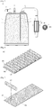
Fig. 1 is a view showing the entire gas adsorption means for an automobile of the related art. -
Figs. 2 to 4 are view showing the gas adsorption means according to an embodiment of the present invention in a canister. -
Fig. 5 is a view showing the gas adsorption means according to an embodiment of the present invention in an auxiliary canister. -
Fig. 6 is a perspective view showing a gas adsorption means according to an embodiment of the present invention. -
Fig. 7 is a perspective view showing a porous body according to an embodiment of the present invention. -
Fig. 8 is a perspective view showing an adsorption block body according to an embodiment of the present invention. -
Fig. 9 shows a reception state of an adsorption block body according to an embodiment of the present invention in perspective views. -
Fig. 10 shows an example of an adsorption means according to an embodiment of the present invention in perspective views. -
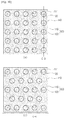
Fig. 11 shows an adsorption means according to an embodiment of the present invention in schematic views, in which the cross-sectional areas A and A' and thelengths 1 and l' of evaporation gas channels are different. - Embodiments of the present invention will be described hereafter in detail with reference to the accompanying drawings. In describing the present invention, well-known functions or constructions will not be described in detail since they may unnecessarily obscure the understanding of the present invention.
- Terminologies defined to describe the present invention are determined in consideration of functions in the present invention and may be changed according to intention of those skilled in the art or customs in the art, so the terminologies should be construed on the basis of the entire specification.
- The gas adsorption means according to the present invention is characterized in that the shape of a porous body including an adsorbent can be easily varied, other than the effective characteristics. In particular, the porous body is shaped such that the vent channels are long and the cross-sectional area of the porous body is small such that the flow rate and direction of evaporation gas concentrates on the vent channels, and the vent channel can ensure flow of the evaporation gas. Accordingly, it is characterized in that adsorption/separation efficiency can be maximized without a loss of evaporation gas adsorbed/separated. Accordingly, the shape of the internal space of a canister is improved to increase the adsorption/separation efficiency, so it is possible to easily achieve various shapes of an adsorption means to correspond to this shape, and accordingly, usability of the adsorption means can be improved.
- For example, the adsorption means can control adsorption/separation efficiency by controlling the ratio A/l of the cross-sectional area A of a porous body through which evaporation gas passes and the length l of a vent channel in the porous body within a predetermined volume, and particularly, it can improve the adsorption/separation efficiency by decreasing A and increasing l.
- As shown in
Fig. 11 , assuming that the cross-sectional area and the length of the vent channels are changed fromFig. 11a to Fig. 11b , that is, to satisfy A>A' and 1<1', if evaporation gas passes through a relatively long vent channel while the evaporation gas passes through vent channels, more evaporation gas can be adsorbed. Accordingly, improvement of adsorption efficiency can be improved. -
Figs. 2 to 5 are views showing the gas adsorption means according to an embodiment of the present invention in a canister.Figs. 2 to 5 show a canister andFig. 6 shows an auxiliary canister combined with a canister. Further, the figures each include a front cross-sectional view and a plan cross-sectional view, that is,Figs. 2 to 4 each provide a front cross-sectional view at the upper portion and a plan cross-sectional view at the lower portion andFig. 5 provides a front cross-sectional view of a canister and an auxiliary canister at the left side and a plan cross-sectional view of an auxiliary canister at the right side. - An adsorption block of an adsorption means according to an embodiment of the present invention is longitudinally shown in the front cross-sectional views and a cross-section vertically taken along the longitudinal direction of the adsorption block of the adsorption means according to an embodiment of the present invention is shown in the plan cross-sectional view.
- As in
Fig. 2 , an adsorption means 100 according to an embodiment of the present invention can be received in the entire inside 140 of ahousing 1 of acanister 10, or as inFigs. 3 and4 , it may be received in a portion of the inside 140 and the other space may be filled with active carbon, as in the related art. - The adsorption means according to the present invention can be applied not only to the
canister 10, but to an auxiliary canister for compensating for and increasing the function of thecanister 100, which is shown inFig. 6 . - The function of a canister will be described to be commonly applied to the configuration shown in
Figs. 2 to 5 . - As shown in
Figs. 2 to 5 , the adsorption means 100 is received in theinternal space 140 of thehousing 1 of thecanister 10 to collect evaporation gas flowing inside through afuel tank port 2. Preferably, the traveling direction of the evaporation gas is the same as the extension direction of the adsorption block of the adsorption means 100, so appropriate vent channels for the evaporation gas and air are formed. However, if necessary, the traveling direction of the evaporation gas may not be the same as the extension direction of the adsorption block of the adsorption means 100, which may be determined in consideration of the sped and the kind of the evaporation gas and air. As compared with a canister filled with only active carbon, theporous body 110 has more vent channels, so gas flow can be improved and back pressure by evaporation gas can be reduced. Further, the adsorption means shown inFig. 2 may further have spaces between theporous bodies 110 in accordance with modifications of the shape, so vent channels can be more surely formed, so it is very advantageous in gas flow. - Further, as shown in the figures, a plurality of adsorption blocks 120 may be formed in parallel in one direction in the
porous body 110, and though not shown, they may be formed in different directions. That is, the direction of the adsorption blocks 120 is not limited to any one direction. - The adsorption means 100 is made of an air-permeable material to allow gas to smoothly flow, so evaporation gas is adsorbed throughout the area and it is possible to prevent evaporation gas from remaining in purging.
- That is, it is possible to increase the ability of collecting evaporation gas by maximizing spatial usability, that is, minimizing a dead zone by increasing air permeability of the adsorption means 100, and it is possible to prevent leakage of evaporation gas by completely burning the adsorbed evaporation gas in purging.
- Further, in the adsorption means 100, as shown in the cross-section 10-1 taken in direction DD in
Fig. 5 , it is preferable that the flow direction of evaporation gas and the longitudinal direction of theadsorption block 120 are in parallel, but the adsorption means 100 may be fixed in the inside 140 such that the flow direction of evaporation gas and the longitudinal direction of theadsorption block 120 are perpendicular to each other, if necessary. Accordingly, the configuration that the flow direction of evaporation gas and the longitudinal direction of theadsorption block 120 are in parallel with each other should be construed as an example in use of the adsorption means 100 of the present invention. - The adsorption means 100, as shown in
Fig. 6 , includes aporous body 110 made of an air-permeable material andadsorption blocks 120 collecting evaporation gas, which will be described in detail with reference toFigs. 6 to 8 . -
Fig. 6 is a perspective view showing an adsorption means according to an embodiment of the present invention,Fig. 7 is a perspective view of a porous body, andFig. 8 is a perspective view of an adsorption block. - The
porous body 110 is a bulk and mesh type of porous sheet, in which the sheet is preferably woven or non-woven fabric, but is not limited thereto, and various sheets made of various materials (for example, metallic mesh) may be used. - The adsorption blocks 120 are continuously arranged with predetermined intervals with the
porous body 110 and bonded to a side of theporous body 110 by any one of heat, ultrasonic waves, and an adhesive, in which the bonding areas are bondingportions 130. - The
adsorption block 120 includes a pocket-shapedenclosing body 123 having porosities and receiving an adsorbent 121 for keeping evaporation gas. - The adsorbent 121 may be particulate active carbon and the enclosing
body 123 is a pocket for keeping the adsorbent 121, that is, the active carbon, and the enclosingbodies 123 are continuously arranged and fixed by any one of heat, ultrasonic waves, and an adhesive on a side of the porous body. - The enclosing
body 123 may be made of an air-permeable material and may be a pocket having porosities at a millimeter or micrometer level corresponding to the adsorbent to prevent separation of the adsorbent 121, and the reason is for preventing separation of the adsorbent 121 and for ensuring smooth venting of gas. - That is, the reason is for improving the ability of keeping evaporation gas and preventing evaporation gas from remaining in purging so that evaporation gas can be smoothly attached and detached.
- The adsorption means 100 of
Fig. 9 may be received in thespace 140 in a coil shape, as inFig. 9a , horizontally stacked in multiple layers, as inFig. 9b , or vertically continuously arranged, as inFig. 9c . - The
adsorption block 120 may be received in various shapes in accordance with the shape of thespace 140. In particular, when the adsorption blocks 120 are received in a coil shape as shown inFig. 9a , it is not limited to a circular shape, but may be wound to correspond to the shape of thespace 140 and it is preferable that one or more adsorption blocks are received in accordance with the size of the space. - Further, adsorption blocks 120 positioned up and down and ahead and behind in
Figs. 9b and 9c may be arranged in the same lines C-1 and C-2, or adsorption blocks 120 positioned up and down and ahead and behind may be alternately arranged, as in the detailed views. - The adsorption means 100 is not limited to the shapes shown in
Figs. 2 to 9 and may be formed in a block shape, as inFig. 10 , and this configuration is described with reference toFig. 10 . -
Fig. 10 shows an example of an adsorption means according to an embodiment of the present invention in perspective views. - As shown in the figures, the adsorption means 100 is a foam block having a size corresponding to the
space 140 and includes aporous body 110 havingholes 111 arranged in several directions with predetermined gaps andadsorption blocks 120 received in theporous body 110. Theporous body 110 is a foam block, for example, a porous sponge. - The
holes 111 are formed with predetermined gaps, as shown inFigs. 10a and 10b , and they may be formed with up and down predetermined gaps along reference lines including a reference line C-3, or they may be alternately arranged up and down along reference lines including a reference line C-4 to achieve smooth flow of gas. - The
holes 111 have a shape corresponding to the shape of the adsorption blocks 120 and are not limited to the shape shown in the figures. Further, as shown in the figures, they may be formed not only in a circle, but a triangle, a rectangle, a polygon, and an ellipse, though not shown in the figures. - The adsorption blocks 120, as shown in
Fig. 10 , may be composed of an adsorbent 121 and an enclosingbody 123 for keeping the adsorbent 121 to be separated out of theporous body 110 through theholes 111, or, although not shown in the figures, theadsorption bocks 120 may be composed of only the adsorbent 121 and inserted in theholes 111, in which the holes may be closed by a specific closing member (for example, a porous material such as woven or non-woven fabric) to prevent the adsorbent 121 from separating from theholes 111. - As described above, by increasing air-permeability of an adsorption means 100 for collecting evaporation gas flowing into a
canister 10 and ensuring vent channels in the adsorption means 100, spatial usability can be increased by minimizing a dead zone and the ability of collecting evaporation gas can be improved. Further, when the collected evaporation gas is purged, the evaporation gas may be completely burned, which is a characteristic of the present invention. - The adsorption blocks 120 according to the present invention are distributed close to vent channels, so most evaporation gas flowing through the vent channels can be collected, and accordingly, adsorption/separation of evaporation gas can be considerably improved, which is also a characteristic of the present invention.
- The present invention was described in detail with reference to examples, but the present invention is not limited thereto and may be modified in various ways without departing from the scope of the present invention. Accordingly, the embodiments described above are provided not to limit the scope of the present invention, but to describe the present invention, so the scope of the present invention should not be construed as being limited by the embodiments. The protective range of the present disclosure should be construed on the basis of claims and all the technical spirits in the equivalent range should be construed as being included in the scope of the right of the present disclosure.
Claims (6)
- A gas adsorption means for an automobile for collecting evaporation gas produced in a fuel tank of a vehicle, the gas adsorption means comprising:a mesh type of porous sheet having vent channels for evaporation gas or air; andadsorption blocks continuously arranged in one direction on the porous sheet to collect the evaporation gas,wherein the adsorption blocks each include:an adsorbent collecting evaporation gas; andan enclosing body keeping the adsorbent and having a pocket shape with porosities.
- The gas adsorption means of claim 1, wherein the adsorption bocks are fixed to the porous sheet by any one of heat, ultrasonic waves, or an adhesive.
- The gas adsorption means of claim 2, wherein the adsorption means is received in a coil shape, or stacked or arranged in multiple layers in a space.
- The gas adsorption means of claim 1, wherein the enclosing bodies are continuously arranged and fixed to a side of the porous sheet by any one of heat, ultrasonic waves, and an adhesive.
- The gas adsorption means of claim 4, wherein the adsorbent is particulate active carbon and the enclosing body is any one of porous non-woven fabric or woven fabric at a millimeter or micrometer level corresponding to the active carbon to prevent separation of the active carbon.
- The gas adsorption means of claim 1, wherein the porous sheet controls adsorption/separation efficiency by controlling a ratio A/1 of a cross-sectional area A through which evaporation gas passes and a length 1 of a vent channel through which the evaporation gas passes within a predetermined volume.
Applications Claiming Priority (2)
| Application Number | Priority Date | Filing Date | Title |
|---|---|---|---|
| KR1020130153491A KR101442071B1 (en) | 2013-12-10 | 2013-12-10 | Adsorption means of gas for vehicles |
| PCT/KR2014/010563 WO2015088143A1 (en) | 2013-12-10 | 2014-11-05 | Gas adsorption means for automobile |
Publications (2)
| Publication Number | Publication Date |
|---|---|
| EP3095996A1 true EP3095996A1 (en) | 2016-11-23 |
| EP3095996A4 EP3095996A4 (en) | 2017-08-09 |
Family
ID=52288942
Family Applications (1)
| Application Number | Title | Priority Date | Filing Date |
|---|---|---|---|
| EP14870361.4A Withdrawn EP3095996A4 (en) | 2013-12-10 | 2014-11-05 | Gas adsorption means for automobile |
Country Status (5)
| Country | Link |
|---|---|
| US (1) | US9970392B2 (en) |
| EP (1) | EP3095996A4 (en) |
| KR (1) | KR101442071B1 (en) |
| CN (1) | CN105793551B (en) |
| WO (1) | WO2015088143A1 (en) |
Families Citing this family (6)
| Publication number | Priority date | Publication date | Assignee | Title |
|---|---|---|---|---|
| JP6725483B2 (en) * | 2017-12-20 | 2020-07-22 | フタバ産業株式会社 | Canister |
| KR102228043B1 (en) * | 2020-07-31 | 2021-03-12 | 현성춘 | canister |
| KR102896419B1 (en) * | 2022-01-07 | 2025-12-05 | 신일화학공업(주) | Canister for vehicle |
| KR102717204B1 (en) * | 2022-11-25 | 2024-10-15 | 코리아에프티 주식회사 | Block for volume control of canister |
| JP7708816B2 (en) * | 2023-07-13 | 2025-07-15 | フタバ産業株式会社 | Canister |
| CN119258723B (en) * | 2024-12-06 | 2025-03-11 | 安徽华中半导体材料有限公司 | A phosphine gas purification device |
Family Cites Families (29)
| Publication number | Priority date | Publication date | Assignee | Title |
|---|---|---|---|---|
| US4386947A (en) * | 1980-04-25 | 1983-06-07 | Nippon Soken, Inc. | Apparatus for adsorbing fuel vapor |
| DE8019041U1 (en) * | 1980-07-16 | 1981-04-16 | Filterwerk Mann & Hummel Gmbh, 7140 Ludwigsburg | INTAKE AIR FILTER OF INTERNAL COMBUSTION ENGINES |
| US4514197A (en) * | 1983-02-15 | 1985-04-30 | Armbruster Joseph M | Filter for air circulator |
| JPS62135168A (en) * | 1985-12-03 | 1987-06-18 | 科研製薬株式会社 | Dehumidifying packaging material |
| US4756726A (en) * | 1986-11-20 | 1988-07-12 | Terry Peace | Regenerable dehumidifier |
| US5354365A (en) * | 1993-04-22 | 1994-10-11 | Youn Kun C | Air filter assembly |
| JP3995881B2 (en) * | 1999-12-28 | 2007-10-24 | 株式会社マーレ フィルターシステムズ | Canister for evaporative fuel treatment |
| US6348086B1 (en) * | 2000-02-16 | 2002-02-19 | 3M Innovative Properties Company | Combination blower wheel and filter cartridge system for HVAC applications |
| JP2002011311A (en) * | 2000-04-28 | 2002-01-15 | Toyoda Spinning & Weaving Co Ltd | Production method for filter material, and filter material |
| JP3565789B2 (en) * | 2001-03-06 | 2004-09-15 | 本田技研工業株式会社 | Evaporative fuel processing equipment |
| KR20020089198A (en) | 2001-05-22 | 2002-11-29 | 코리아에프티 주식회사 | Activated carbon intergrated air fillter installation |
| WO2003047721A1 (en) * | 2001-12-04 | 2003-06-12 | Fleetguard, Inc. | Melt-spun ceramic fiber filter and method |
| JP2003214264A (en) * | 2002-01-22 | 2003-07-30 | Nippon Soken Inc | Evaporative fuel adsorption device |
| JP3892385B2 (en) * | 2002-10-22 | 2007-03-14 | 株式会社デンソー | Canister filter |
| US7344586B2 (en) * | 2003-03-19 | 2008-03-18 | Honeywell International, Inc. | Evaporative emissions filter |
| US7160361B2 (en) * | 2003-10-15 | 2007-01-09 | Delphi Technologies, Inc. | Evaporative emission treatment device |
| DE102004018184A1 (en) * | 2004-04-14 | 2005-11-10 | Mann + Hummel Gmbh | Adsorption element for the adsorption of vapors |
| DE102004000050B4 (en) * | 2004-11-17 | 2008-07-31 | Mann + Hummel Gmbh | Filter element, in particular cabin filter, to the frontal flow |
| DE102004063434B4 (en) * | 2004-12-23 | 2009-03-19 | Mann+Hummel Innenraumfilter Gmbh & Co. Kg | Activated carbon moldings, process for its preparation and its use |
| JP2006214403A (en) * | 2005-02-07 | 2006-08-17 | Aisan Ind Co Ltd | Evaporative fuel processing equipment |
| FR2890340A1 (en) | 2005-09-05 | 2007-03-09 | Inergy Automotive Systems Res | HEATING DEVICE FOR CANISTER |
| KR100736418B1 (en) * | 2006-02-08 | 2007-07-16 | 코리아에프티 주식회사 | Canister assembly |
| KR100821732B1 (en) | 2006-12-26 | 2008-04-14 | 어플라이드 세라믹스 아이엔씨 | Adsorptive monoliths comprising activated carbon, methods of making such monoliths, and methods of adsorbing chemicals from a fluid stream |
| JP2009144684A (en) * | 2007-12-18 | 2009-07-02 | Aisan Ind Co Ltd | Fuel vapor treatment apparatus |
| KR20100104366A (en) * | 2009-03-17 | 2010-09-29 | 지엠 글로벌 테크놀러지 오퍼레이션스, 인코포레이티드 | Canister having ventilation material including charcoal |
| CN201500494U (en) * | 2009-04-24 | 2010-06-09 | 张延青 | Activated carbon filtering device |
| CN201527060U (en) * | 2009-10-26 | 2010-07-14 | 牛泽 | Civil air conditioner air purifier |
| KR101028668B1 (en) | 2010-06-22 | 2011-04-12 | 코리아에프티 주식회사 | Canister with heater |
| KR101092577B1 (en) | 2010-07-27 | 2011-12-13 | 한국기계연구원 | Method for preparing a three-dimensional complex cell support in the form of a tube |
-
2013
- 2013-12-10 KR KR1020130153491A patent/KR101442071B1/en not_active Expired - Fee Related
-
2014
- 2014-11-05 EP EP14870361.4A patent/EP3095996A4/en not_active Withdrawn
- 2014-11-05 WO PCT/KR2014/010563 patent/WO2015088143A1/en not_active Ceased
- 2014-11-05 CN CN201480066735.2A patent/CN105793551B/en not_active Expired - Fee Related
- 2014-11-05 US US15/103,313 patent/US9970392B2/en active Active
Also Published As
| Publication number | Publication date |
|---|---|
| US9970392B2 (en) | 2018-05-15 |
| CN105793551B (en) | 2019-01-29 |
| CN105793551A (en) | 2016-07-20 |
| US20160319777A1 (en) | 2016-11-03 |
| EP3095996A4 (en) | 2017-08-09 |
| WO2015088143A1 (en) | 2015-06-18 |
| KR101442071B1 (en) | 2014-11-04 |
Similar Documents
| Publication | Publication Date | Title |
|---|---|---|
| US9970392B2 (en) | Gas adsorption means for automobile | |
| CN104279090B (en) | Evaporated fuel treating apparatus | |
| ES2827228T3 (en) | Filter element, in particular air filter element, and filter system with a filter element | |
| US6503301B2 (en) | Fuel vapor treatment canister | |
| US7160361B2 (en) | Evaporative emission treatment device | |
| US10508620B2 (en) | Evaporated fuel treatment device | |
| CN102159823B (en) | fuel vapor storage | |
| JP3942887B2 (en) | Evaporative fuel adsorbent and air cleaner | |
| JP7322086B2 (en) | Honeycomb adsorbent, manufacturing method thereof, and canister | |
| US20090301071A1 (en) | Low restriction hydrocarbon trap assembly | |
| US10184431B2 (en) | Fuel vapor processing apparatus | |
| KR20200013787A (en) | Evaporative Ejector and Adsorbent | |
| US20160377032A1 (en) | Vaporized fuel treatment device | |
| JP6628992B2 (en) | Evaporative fuel processing device | |
| US20020073847A1 (en) | Cell within a cell monolith structure for an evaporative emissions hydrocarbon scrubber | |
| CN202832866U (en) | Fuel steam carbon tank, hydrocarbon storage carbon tank and vehicle series | |
| CN111535946B (en) | filter unit for canister | |
| US20210033048A1 (en) | Fuel Vapor Processing Apparatus | |
| JP2013245593A (en) | Evaporated fuel treatment apparatus | |
| JP2002292277A (en) | Adsorbing sheet | |
| KR101685498B1 (en) | Canister | |
| JP4394104B2 (en) | Evaporative fuel adsorbent | |
| US20260104020A1 (en) | Evaporative emissions canister with non-adsorbent, low flow-restriction zone | |
| JP4057345B2 (en) | Evaporative fuel collector for internal combustion engine | |
| KR20100104366A (en) | Canister having ventilation material including charcoal |
Legal Events
| Date | Code | Title | Description |
|---|---|---|---|
| PUAI | Public reference made under article 153(3) epc to a published international application that has entered the european phase |
Free format text: ORIGINAL CODE: 0009012 |
|
| PUAB | Information related to the publication of an a document modified or deleted |
Free format text: ORIGINAL CODE: 0009199EPPU |
|
| PUAI | Public reference made under article 153(3) epc to a published international application that has entered the european phase |
Free format text: ORIGINAL CODE: 0009012 |
|
| 17P | Request for examination filed |
Effective date: 20160704 |
|
| AK | Designated contracting states |
Kind code of ref document: A1 Designated state(s): AL AT BE BG CH CY CZ DE DK EE ES FI FR GB GR HR HU IE IS IT LI LT LU LV MC MK MT NL NO PL PT RO RS SE SI SK SM TR |
|
| AX | Request for extension of the european patent |
Extension state: BA ME |
|
| DAX | Request for extension of the european patent (deleted) | ||
| A4 | Supplementary search report drawn up and despatched |
Effective date: 20170711 |
|
| RIC1 | Information provided on ipc code assigned before grant |
Ipc: F02M 25/08 20060101AFI20170706BHEP Ipc: B60K 15/03 20060101ALI20170706BHEP |
|
| 17Q | First examination report despatched |
Effective date: 20180309 |
|
| STAA | Information on the status of an ep patent application or granted ep patent |
Free format text: STATUS: THE APPLICATION IS DEEMED TO BE WITHDRAWN |
|
| 18D | Application deemed to be withdrawn |
Effective date: 20180720 |