EP3095015B1 - Vorrichtung und verfahren zum betrieb einer automatisierungsanlage mit reduziertem energieverbrauch - Google Patents
Vorrichtung und verfahren zum betrieb einer automatisierungsanlage mit reduziertem energieverbrauch Download PDFInfo
- Publication number
- EP3095015B1 EP3095015B1 EP14712228.7A EP14712228A EP3095015B1 EP 3095015 B1 EP3095015 B1 EP 3095015B1 EP 14712228 A EP14712228 A EP 14712228A EP 3095015 B1 EP3095015 B1 EP 3095015B1
- Authority
- EP
- European Patent Office
- Prior art keywords
- control system
- automation
- energy
- switching
- information signals
- Prior art date
- Legal status (The legal status is an assumption and is not a legal conclusion. Google has not performed a legal analysis and makes no representation as to the accuracy of the status listed.)
- Active
Links
Images
Classifications
-
- G—PHYSICS
- G05—CONTROLLING; REGULATING
- G05B—CONTROL OR REGULATING SYSTEMS IN GENERAL; FUNCTIONAL ELEMENTS OF SUCH SYSTEMS; MONITORING OR TESTING ARRANGEMENTS FOR SUCH SYSTEMS OR ELEMENTS
- G05B15/00—Systems controlled by a computer
- G05B15/02—Systems controlled by a computer electric
-
- G—PHYSICS
- G05—CONTROLLING; REGULATING
- G05B—CONTROL OR REGULATING SYSTEMS IN GENERAL; FUNCTIONAL ELEMENTS OF SUCH SYSTEMS; MONITORING OR TESTING ARRANGEMENTS FOR SUCH SYSTEMS OR ELEMENTS
- G05B2219/00—Program-control systems
- G05B2219/20—Pc systems
- G05B2219/25—Pc structure of the system
- G05B2219/25289—Energy saving, brown out, standby, sleep, powerdown modus for microcomputer
-
- G—PHYSICS
- G05—CONTROLLING; REGULATING
- G05B—CONTROL OR REGULATING SYSTEMS IN GENERAL; FUNCTIONAL ELEMENTS OF SUCH SYSTEMS; MONITORING OR TESTING ARRANGEMENTS FOR SUCH SYSTEMS OR ELEMENTS
- G05B2219/00—Program-control systems
- G05B2219/20—Pc systems
- G05B2219/25—Pc structure of the system
- G05B2219/25291—Set module, component to sleep if no event or no other module needs it
Definitions
- the invention relates to a device for operating an automation system and a corresponding method.
- Automation systems are used to carry out predetermined process sequences in an automated manner using technical equipment. Automation systems are often used for the industrial production of goods or products. Another example of an automation system is a logistic distribution system.
- Automation systems are usually complex and include a large number of sub-systems.
- the problem here is that the subsystems are often not operated in an energy-efficient manner.
- subsystems often remain in operation even though they are not required for the automation system processes that have just been carried out.
- the publication [2] describes a device for the energy-efficient control of a system.
- the system can be set to energy-saving status.
- Document [3] discloses a method for automatically creating switch-on sequences in an industrial plant with the lowest possible total energy consumption in the plant.
- the object of the invention is to create a device for operating an automation system which simply and efficiently controls the energy consumption of the system.
- the device comprises an automation control system which comprises a process control unit for controlling the processes carried out by the automation system.
- the process control unit is usually a programmable logic controller (also referred to as a PLC controller).
- the process control unit accesses several device control units, which can also be implemented as a programmable logic controller.
- a respective device control unit is assigned to a subsystem of the automation system and controls the devices belonging to this subsystem.
- the automation control system is provided for controlling the automation system on the control level and / or the process control level in accordance with the automation pyramid.
- the automation pyramid is well known to the person skilled in the art and describes the various levels in which tasks are carried out by the automation system.
- the automation pyramid is composed from bottom to top of the sensor / actuator level, the field level, the control level, the process control level, the plant control level and the company level.
- the device according to the invention comprises a superordinate control system which Has access to the automation control system to influence the operation of the automation system.
- This superordinate control system is preferably provided above the process control level in accordance with the automation pyramid, preferably in the operations control level.
- the device further comprises an energy control system for determining and executing switching sequences, the energy control system issuing switching commands to the automation control system as part of the execution of a switching sequence, whereby devices of the subsystems are at least temporarily switched to operating states with reduced energy consumption.
- Switching to operating states with reduced energy consumption takes place without affecting the operation of the automation system.
- the switching to operating states with reduced energy consumption takes place in such a way that the currently running processes of the automation system continue to be carried out or the system or corresponding parts of the system are currently stopped.
- Operating states with reduced energy consumption are, in particular, standby states or also completely switched-off states of devices in the automation system.
- the device includes an interface for outputting first information signals from the process control unit to the energy control system, the first information signals specifying one or more subsystems and / or devices thereof (ie at least one device) carried out by the automation system Processes are not needed at least temporarily, ie which are not needed in one or more periods (currently and / or in the future) determined by the processes.
- the device includes an interface for outputting second information signals from the superordinate control system to the energy control system, wherein the second information signals specify at least one pending operational stop (ie a current or future operational stop) of one or more subsystems and / or devices thereof (ie at least one device).
- the second information signals specify an upcoming shutdown of the entire automation system.
- the energy control system of the device according to the invention is designed in such a way that it calculates and executes the switching sequences as a function of the first and second information signals.
- the device according to the invention is characterized by comprehensive regulation of the energy consumption of an automation system, taking into account both a higher-level control system and the automation control system.
- the ongoing processes of the automation system and the information on operational stoppages from a higher-level control system are taken into account.
- the term “shutdown” is understood to mean a period of time in which the automation system does not perform its automation tasks, i.e. a period of time in which the automation system is not working productively.
- MES Manufacturing Execution System
- Such a production control system is assigned to the operations control level of the automation pyramid.
- the operational planning system is designed in such a way that it creates the temporal operating sequence of the automation system and determines the operational stoppages contained in this temporal operating sequence.
- an existing operational planning system can be integrated into the control of the energy consumption of the automation system in a simple manner.
- the operational planning system preferably comprises a separate creation logic for creating the temporal operating sequence and a separate determination logic for determining the operating stops contained in this temporal operating sequence, the determination logic accessing the creation logic for determining the operating stops.
- the energy control system is designed in such a way that it determines the switching sequences based on an energy state model, according to which the devices of the subsystems based on the criterion of the lowest possible energy consumption of one or more parts of the automation system and in particular the entire automation system and / or the criterion of low wear of one or more parts of the automation system can be switched to operating states with reduced energy consumption.
- Parts of the automation system can be understood to mean individual devices or combinations of several devices and possibly also subsystems.
- a common interface is provided for the higher-level control system and the process control unit in order to output the first and second information signals to the energy control system. This creates a simple transfer of first and second information to the energy control system.
- the energy control system has a separate calculation logic for calculating switching sequences and a separate execution logic for executing the switching sequences, the calculation logic for initializing the execution of a calculated switching sequence based on the execution logic accesses.
- a switching control unit is provided in the automation control system for each subsystem, which switching commands of the energy control system are converted into commands that can be processed by the device control unit of the respective subsystem. In this way, a generic connection of the energy control system to the automation control system can be achieved.
- the device according to the invention for operating an automation system is provided in the form of a system for manufacturing goods or products or in the form of a logistic distribution system.
- the invention also relates to an automation system which comprises the device according to the invention described above or one or more preferred variants of this device.
- the method according to the invention is preferably designed in such a way that the automation system is operated with the device according to the invention or one or more preferred variants of the device according to the invention.
- Corresponding features of the device are implemented as corresponding method features in the operating method.
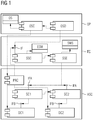
- Fig. 1 the architecture of an embodiment of a device according to the invention is described.
- the control logic of the automation system is coupled with components of an energy control system, which controls the switching into states with reduced energy consumption in relation to individual subsystems of the automation system.
- States with reduced energy consumption can be defined differently depending on the configuration of the automation system.
- states with reduced energy consumption include standby states and switched-off states of corresponding devices at the level of a subsystem of the automation system.
- MES Manufacturing Execution System
- the architecture shown here describes interfaces between the various components.
- the interfaces determine the communication between the components, which is required for automated, energy-saving switching at the subsystem level.
- a protocol is specified that describes the interaction of the components in relation to the interfaces.
- FIG. 1 the architecture is shown in the form of a known UML component diagram.
- the access of a component (specified by the beginning of the arrow) to another component (specified by the end of the arrow) is shown by dashed arrows.
- ASC Automation System Control
- This control system contains, in a manner known per se, a process control unit (for example a PLC control), which in turn controls individual device control units of subsystems of the automation system.
- Fig. 1 two device control units DC1 and DC2 are shown by way of example, with a significantly larger number of device control units being provided as a rule. Each of these device control units controls corresponding devices in the subsystem under consideration.
- the devices represent, among other things, sensors and actuators in the automation system.
- the automation control system ASC is a control system on the process control level and the control level according to the automation pyramid.
- EC Energy Controller
- the switching control units convert or convert commands from the energy control system into commands which can be processed by the individual device control units DC1 or DC2.
- the OSD logic accesses the OSC logic to determine or detect operational stops.
- the OSD logic determines in which Periods of time the entire automation system can be switched off.
- the aforementioned energy control system EC receives first information signals IN1 from the process control unit PRC and second information signals IN2 from the logic OSD via an interface IF.
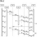
- the information signals IN1 and IN2 are shown in the timing diagram of FIG Fig. 2 shown.
- the first information signals contain information with regard to subsystems or devices thereof that are currently not required by the processes carried out by the automation system and can therefore be switched off or put into an energy-saving mode.
- the second information signals relate to information on pending operational stops of the system, which were detected via the logic OSD by means of an access to the logic OSC. Both pieces of information are given via the interface IF to a logic SSC which calculates the switching sequences SWS.
- the switching sequences specify, taking into account the information signals IN1 and IN2, when corresponding devices of subsystems or entire subsystems or the entire automation system can be switched to states with reduced energy requirements without the operation of the automation system being impaired as a result.
- the logic SSC accesses an energy state model ESM, according to which the switching sequences SWS are defined in such a way that the energy consumption of the entire automation system is as low as possible.
- ESM energy state model
- the type of calculation of corresponding switching sequences with such an energy state model is known per se. As an example, reference is made to the procedures in documents [4], [5] and [6].
- the logic SSC also interacts with the logic SSE, which executes the calculated switching sequences and for this purpose accesses the data object SWS of the switching sequences.
- This component is known per se and is part of the operational planning system OP. It provides an administrative functionality for creating the sequence of operations of the automation system. For this purpose it accesses the data object OS.
- This component which is located within the operations planning system OP, provides a functionality according to which production stops of the automation system or parts thereof are derived from the temporal operating sequence of the automation system.
- the OSD logic accesses the OSC logic, which creates the operational sequence over time.
- This component provides the functionality of calculating energy-efficient switching sequences based on information from the logic OSD and the process control unit PRC.
- the basis for the calculations carried out is the energy state model ESM of the automation system and its subsystems.
- the logic SSC accesses the logic SSE for executing switching sequences in order to cause the calculated switching sequences to be executed.
- the SSE logic sends corresponding commands to the automation control system ASC, which forwards these commands via the respective interfaces IFA to the switching control units SC1 or SC2, which in turn convert the commands into commands for the device control units DC1 or DC2 .
- These commands are output to these device control units via the IFB interface.
- this component executes switching sequences by transferring switching commands to the automation control system ASC.
- the currently executed switching sequence is tracked at all times.
- the component SSE accesses the switching control units SC1 and SC2, which are provided in the automation control system ASC and enable the simultaneous switching of different subsystems of the automation system.
- This component is part of the automation control system ASC and has the functionality of controlling the processes carried out by the automation system. For this purpose, it accesses various device control units DC1 and DC2 in a manner known per se, which are responsible for controlling various subsystems of the automation system.
- the process control unit PRC accesses the logic SSC for calculating switching sequences via the interface IF in order to communicate the corresponding first information signals relating to devices that are currently not required in the processes carried out by the automation system.
- This component directly controls a specific subsystem of the automation system.
- This component is arranged above each device control unit as a communication layer to the energy control system EC.
- the component receives switching commands from the SSE logic to execute the switching sequences and, after appropriate conversion, forwards them to the subsystems of the automation system.
- This interface is referred to below as "ActivationScheduling" and is specified by the following UML class diagram: ⁇ interface>> Activation Scheduling + scheduleSystemActivation () + scheduleSubsystemActivation () + scheduleSystemDeactivation () + scheduleSubsystemDeactivation ()
- the entire automation system can be activated or deactivated using the scheduleSystemActivation () or scheduleSystemDeactivation () functions.
- the functions scheduleSubsystemActivation () or scheduleSubsystemDeactivation () can be used to activate or deactivate subsystems of the automation system.
- the interface IF enables communication between the logic OSC for determining operational stops or the process control unit PRC with the logic SSC for calculating switching sequences.
- the IFA interface is referred to below as "StateSwitching" and is specified by the following UML class diagram: ⁇ interface>> StateSwitching + switchToState () + requestCurrentState () A corresponding switching command is given to the switching control unit SC1 or SC2 via the switchToState () function.
- the requestCurrentState () function is used to request information about the current switching status from the corresponding switching control unit.
- This interface enables communication between the individual switching control units, installed in the various subsystems and the SSE logic for executing the switching sequences. The main purpose of this interface is to switch subsystems into certain states. Since errors can occur when switching, the current switching status of the subsystems can be queried.
- DeviceModeControlling This interface is referred to below as DeviceModeControlling and is specified by the following UML class diagram: ⁇ interface>> DeviceModeControlling + setDeviceMode () + getDeviceMode ()
- the setDeviceMode () function is used to set the states of devices in the corresponding subsystem.
- the current status of devices in the subsystem can also be called up using the getDeviceMode () command.
- the interface enables communication between the switching control units SC1 or SC2 and the device control units DC1 or DC2 assigned to these switching control units.
- Fig. 2 the timing of a communication protocol for information exchange in the architecture of the Fig. 1 described.
- time advances vertically from top to bottom, with periods of activity of corresponding components being indicated by vertical bars.
- the transfer of information between individual components is indicated by arrows running horizontally.
- the Component OSD determines the above-described second information signals IN2, which are given to component SSC.
- the information IN2 specifies an operational stop of the entire automation system.
- the component SSC then calculates the corresponding switching sequence SWS taking into account the second information signals, which is specified by step S1.
- all subsystems of the automation system are switched off with corresponding switching commands ST1, ST2, ..., etc., as indicated by step S2.
- Fig. 2 gives the process control unit PRC of the automation control system ASC at regular intervals commands CO to the individual device control units DCi in order to control them accordingly.
- Event EV finally occurs, which indicates that a subsystem is currently not required in the processes carried out by the automation system.
- a corresponding first information signal IN1 which specifies the subsystem that is not required, is given to the component SSC.
- step S3 the subsystem that is not required is then switched off via a second switching sequence SWS.
- Corresponding commands are given within the switching sequence to the device control unit of the subsystem that is to be switched off. This is achieved by the command SB, which is given to the switching control unit SCi of the subsystem and specifies that the entire subsystem can be put into standby mode.
- the switching control unit SCi then converts this command into the command SM, which is given to the corresponding device control unit DCi and there causes the deactivation of the subsystem.
- the subsystem As soon as the subsystem is required again within the framework of the processes carried out by the automation system, it is returned to the standby state via the commands SR and SM ' switched.
- the command SR is given to the switching control unit SCi, which converts this command into the command SM 'for activating the corresponding device control unit DCi.
- the time span NC between the commands SM and SM ' is also indicated.
- the subsystem that is not required is switched off within this period of time and cannot be controlled via the process control unit PRC.
- the embodiment of the invention described above has a number of advantages.
- a separation of an energy-efficient control of the components of an automation system from the actual process control is achieved.
- the energy control system functions as an abstraction layer for activating and deactivating subsystems.
- the programming of an energy-saving behavior of the automation system is facilitated, since the energy control system is configured as a separate unit and is not part of a PLC program within the automation control system.
- the programmer of a PLC control for the automation control system therefore only needs to implement suitable interfaces to the energy control system.
- the activation and deactivation of corresponding devices is carried out separately via the energy control system. In this way it becomes easier to make changes to the control or to determine malfunctions, because a well-structured interaction between the components in the system is defined.
- the above architecture By processing information about the processes carried out by the automation system (first information signals), the above architecture enables subsystems of the automation system that are currently not required to be switched off. This saves energy without reducing the productivity of the plant.
- the architecture of the Fig. 1 provides mechanisms for deactivating the system from two directions.
- the plant can be shut down as a whole via an operations planning system.
- subsystems can be switched off while the automation system is in operation, for example taking into account corresponding signals in the automation process that indicate that certain devices or subsystems are not required.
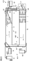
- the automation system is a prototype consisting of the four modules MO1, MO2, MO3 and MO4.
- a module represents a subsystem of the automation system.
- the system with the individual modules is in Fig. 3 shown in plan view from above.
- the modules MO1, MO2, MO3 and MO4 each include a conveyor belt B1, B2, B3 or B4, the transport directions of the belts being indicated by corresponding arrows P.
- Each module has an electric motor to drive its conveyor belt.
- the conveyor belt B1 is driven by the motor M1, the conveyor belt B2 by the motor M2, the conveyor belt B3 by the motor M3 and the conveyor belt B4 by the motor M4.
- Each module also includes a power module for supplying electrical power and a corresponding one Inverter for power conversion to operate the electrical components of the module.
- the power modules and inverters are not off Fig. 3 evident.
- various sensors are provided in the system. In Fig. 3 the light barriers LB1, LB2, LB2 'and LB3 are indicated here.
- the system is controlled by a PLC control.
- Energy meters are also provided for measuring the energy consumption of all modules. Communication with a user takes place via an MMI interface in the form of a screen (not shown).
- Fig. 3 The system shown serves to transport round plastic chips over the individual conveyor belts in such a way that the arrangement of the chips on conveyor belt B3 results in a lettering Fig. 3 just the letters "YOU" are reproduced.
- the individual chips are in Fig. 3 indicated as white circles and only partially given the reference number 1 for reasons of clarity.
- the structure of the individual modules MO1 to MO4 is described in more detail below.
- the module MO1 comprises the conveyor belt B1 with the associated motor M1 and a further motor DM1, which supports the transport of the chips to a narrowing area at the end of the belt B1. From the module MO1, the chips reach the module MO2 via the narrowing area.
- the module MO2 comprises the conveyor belt B2 with an assigned motor M2 as well as the further motor DM2 and a column shifting mechanism CP.
- the motor DM2 transports the chips from the conveyor belt B1 to the conveyor belt B2.
- the chips are transferred in such a way that respective columns of chips for a letter to be generated are formed on the conveyor belt B2.
- the corresponding column of chips is transferred to the conveyor belt B3 of the module MO3 via the column shifting mechanism CP of the module MO2.
- a process control unit PRC and four separate device control units DC1, DC2, DC3 and DC4 with assigned switching control units are provided for the respective modules MO1, MO2, MO3 and MO4.
- an energy control system EC implemented via PLC software.
- the energy control system EC is connected to the automation control system ASC of the automation system via OPC communication.
- the energy control system includes the based on Fig. 1 described functionalities of the calculation and execution of energy-efficient switching sequences. The calculation of these switching sequences is based on an energy state model, which is explained in the documents [4] to [6] mentioned at the beginning.
- an operations planning system OP is also provided, which regulates the timing of the operations of the system to generate corresponding letters.
- the operational sequence is divided into individual jobs, each job relating to the generation of a word on the conveyor belt B3.
- JobNo. text Number of chips per column Start of production (time) Duration of the production process [min] Duration of the production break e [min] 2401 SIEMENS 7th 10:20 00:05 0 2402 INVENTION 7th 10:25 00:07 3 2403 REPORT 5 10:35 00:03 22nd 2404 MUNICH 5 11:00 00:03 57 2405 BERLIN 7th 12:00 00:05
- the (maximum) number of chips per column of a letter can differ.
- Fig. 3 a scenario is shown in which five chips are used per column. By replacing the chips with smaller chips, letters with seven chips per column can also be generated.
- the module MO4 is considered, the conveyor belt B4 of which only has to move when the chips are output from the conveyor belt B3 after being displayed. In other words, there is the possibility that the conveyor belt is switched off temporarily to save energy.
- all modules MO1 to MO4 only have to be active if a corresponding job is active according to the table above. If there is a sufficiently long interruption time between jobs according to the table above, all modules can be switched off or switched to an energy-saving state.
- a control of the plant is made Fig. 3 in the case of production stoppages or breaks in production, which result from the table above.
- the time sequence of the jobs from the table above comes from the logic OSC Fig. 1 whereas the logic OSD is off Fig. 1 the time periods for the corresponding production stops (right column of the table) are determined.
- the number of chips per column is changed between jobs 2402 and 2403, which involves an exchange of chips that takes three minutes.
- the entire automation system can be switched off, since no "production" takes place at all in the sense that words are reproduced via the conveyor belt B3.
- the corresponding (second) information signal about this production break is according to Fig. 1 given via the interface IF to the energy control system EC, which uses the logic SSC and SSE to determine an energy-optimized switching sequence which takes into account the corresponding time specifications in the execution of the jobs, but tries to operate the system with the greatest possible energy savings.
- all four modules MO1 to MO4 are completely switched off.
- the signal of the rising edge of the light barrier LB3 is given via the process control unit PRC to the energy control system EC, which uses this signal as an input for calculating the switching sequences.
- the process control unit PRC uses this signal as an input for calculating the switching sequences.
- both conveyor belt B3 of module MO3 and conveyor belt B4 of module MO4 are switched on.
- the time span for how long the corresponding modules remain switched on depends on the current situation, for example on how many chips are already present on the conveyor belt B3.
- the SSC logic calculates the corresponding time span in which the modules MO3 and MO4 remain switched on, according to the current situation.
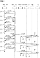
- Fig. 4 shows a timing diagram which again clarifies the activation or deactivation of the modules MO3 and MO4 just described.
- the vertical direction from top to bottom again corresponds to the progression of time and bars assigned to the components represent time spans in which the components are active.
- their assigned device control units DC1 to DC4 are also specified.
- the process control unit PRC and the energy control system EC are also shown.
- “LB 1 RE” designates a rising edge of the light barrier LB1 and “LB 1 FE” a falling edge of the light barrier LB1.
- LB 3 RE denotes a rising edge of the light barrier LB3.
- the diagram of the Fig. 4 shows all active periods of the individual modules and their interaction with the other modules. It describes the display of the letter "C". This letter is made up of three consecutive columns, whereby the first column contains five chips, the second column contains two chips and the third column also contains two chips. The chips in the first column are in Fig. 4 labeled C11, C12, C13, C14 and C15. In contrast, the chips in the second column are labeled C21 and C22. The chips in the third column are correspondingly referred to as C31 and C32. Furthermore, the passage of time is the Fig. 4 also the chip C11 'of the next letter to be reproduced is indicated.
- module MO1 is initially active. Finally, a rising edge is output by the light barrier LB1 due to the transport of the chip C11 to the end of the conveyor belt B1. As a result, the module MO2 starts, whereas the module MO1 is stopped. After the transfer of the chip C11 to the module MO2, a falling edge is generated by the light barrier LB1. As a result, the module MO1 is reactivated to transport the next chip C12. This procedure is continued until the first column of the letter C is transferred to the conveyor belt B2. In Fig.
- LB 1 also indicates the case that the chip C13 immediately follows the chip C12 and thus the rising edge "LB 1 RE” generated by the chip C12 is only followed again by a falling edge "LB 1 FE” when the chip C13 has passed the light barrier LB1.
- the Fig. 1 a rising edge “LB 3 RE” on the light barrier LB3, which is caused by the mechanism CP due to the sliding of the first column of the letter “C” onto the conveyor belt B3.
- This rising edge leads to the process control unit PRC receiving corresponding information IN1 to the energy control system EC, which then activates both the module MO3 and the module MO4, as indicated by the arrows AS and AS '.
- This scenario is repeated accordingly with the transfer of the second column and the third column of the letter C, as can be seen from the illustration of Fig. 4 reveals.
- the time span of the activation of the modules MO3 and MO4 is calculated according to the current situation.
- the modules are then switched off again.
- the module MO3 If the module MO3 is deactivated, it is switched to a standby state, since it has to be switched on again quickly when the chips are transferred by the mechanism CP.
- the module MO4 can be switched to the switched-off state when it is deactivated, since the transfer of the chips from the conveyor belt B3 to the conveyor belt B4 is not time-critical.
Landscapes
- Engineering & Computer Science (AREA)
- General Engineering & Computer Science (AREA)
- Physics & Mathematics (AREA)
- General Physics & Mathematics (AREA)
- Automation & Control Theory (AREA)
- General Factory Administration (AREA)
- Programmable Controllers (AREA)
Description
- Die Erfindung betrifft eine Vorrichtung zum Betrieb einer Automatisierungsanlage sowie ein entsprechendes Verfahren.
- Automatisierungsanlagen dienen dazu, vorbestimmte Verfahrensabläufe automatisiert über technische Einrichtungen durchzuführen. Häufig werden Automatisierungsanlagen zur industriellen Herstellung von Gütern bzw. Produkten genutzt. Ein weiteres Beispiel einer Automatisierungsanlage ist ein logistisches Verteilsystem.
- Automatisierungsanlagen sind in der Regel komplex aufgebaut und umfassen eine Vielzahl von Teilsystemen. Dabei besteht das Problem, dass die Teilsysteme oftmals nicht energieeffizient betrieben werden. Insbesondere bleiben Teilsysteme oftmals im Betrieb, obwohl sie für die gerade durchgeführten Prozesse der Automatisierungsanlange nicht benötigt werden.
- Aus dem Stand der Technik Ansätze bekannt, um Automatisierungsanlangen energiesparend zu betreiben. In der Druckschrift [1] ist eine Vorrichtung zum Reduzieren des Energieverbrauchs einer Anlage beschrieben, bei der die Anlage über ein Deaktivierungssignal in verschiedene Energiesparmodi gesetzt werden kann.
- Die Druckschrift [2] beschreibt eine Vorrichtung zur energieeffizienten Steuerung einer Anlage. Mit Informationen aus übergeordneten Systemen, z.B. einem Produktplanungssystem, kann die Anlage in energiesparende Zustände gesetzt werden.
- Das Dokument [3] offenbart ein Verfahren zur automatischen Erstellung von Einschaltsequenzen in einer industriellen Anlage mit möglichst geringer Gesamt-Energieaufnahme in der Anlage.
- Die bekannten Verfahren zum energieeffizienten Betrieb von technischen Anlagen zeigen keine konkrete Umsetzung, wie der Energieverbrauch der Anlage unter Berücksichtigung der Wechselwirkung mit verschiedenen Steuersystemen geeignet angepasst werden kann.
- Aufgabe der Erfindung ist es, eine Vorrichtung zum Betrieb einer Automatisierungsanlange zu schaffen, welche einfach und effizient den Energieverbrauch der Anlage steuert.
- Diese Aufgabe wird durch die unabhängigen Ansprüche gelöst. Weiterbildungen der Erfindung sind in den abhängigen Ansprüchen definiert.
- Die erfindungsgemäße Vorrichtung umfasst ein Automatisierungs-Steuersystem, das eine Prozess-Steuereinheit zur Steuerung der durch die Automatisierungsanlange durchgeführten Prozesse umfasst. Üblicherweise ist die Prozess-Steuereinheit eine speicherprogrammierbare Steuerung (auch als SPS-Steuerung bezeichnet). Die Prozess-Steuereinheit greift im Rahmen der Steuerung auf mehrere Gerätesteuereinheiten zu, die ebenfalls als speicherprogrammierbare Steuerung realisiert sein können. Eine jeweilige Gerätesteuereinheit ist einem Teilsystem der Automatisierungsanlange zugeordnet und steuert die zu diesem Teilsystem gehörigen Geräte. In einer bevorzugten Variante ist das Automatisierungs-Steuersystem zur Steuerung der Automatisierungsanlange auf der Steuerungsebene und/oder der Prozessleitebene gemäß der Automatisierungspyramide vorgesehen. Die Automatisierungspyramide ist dem Fachmann hinlänglich bekannt und beschreibt die verschiedenen Ebenen, in der Aufgaben durch die Automatisierungsanlange durchgeführt werden. Die Automatisierungspyramide setzt sich von unten nach oben aus der Sensor/Aktor-Ebene, der Feldebene, der Steuerungsebene, der Prozessleitebene, der Betriebsleitebene und der Unternehmensebene zusammen.
- Die erfindungsgemäße Vorrichtung umfasst neben dem Automatisierungs-Steuersystem ein übergeordnetes Steuersystem, welches Zugriff auf das Automatisierungs-Steuersystem zur Beeinflussung des Betriebs der Automatisierungsanlange hat. Vorzugsweise ist dieses übergeordnete Steuersystem oberhalb der Prozessleitebene gemäß der Automatisierungspyramide vorgesehen, vorzugsweise in der Betriebsleitebene.
- Die erfindungsgemäße Vorrichtung umfasst ferner ein Energie-Steuersystem zur Ermittlung und Ausführung von Schaltsequenzen, wobei das Energie-Steuersystem im Rahmen der Ausführung einer Schaltsequenz Schaltbefehle an das Automatisierungs-Steuersystem gibt, wodurch Geräte der Teilsysteme zumindest zeitweise in Betriebszustände mit reduziertem Energieverbrauch geschaltet werden. Das Schalten in Betriebszustände mit reduziertem Energieverbrauch erfolgt dabei ohne Beeinträchtigung des Betriebs der Automatisierungsanlange. Mit anderen Worten erfolgt das Schalten in Betriebszustände mit reduziertem Energieverbrauch derart, dass die aktuell laufenden Prozesse der Automatisierungsanlange weiterhin durchgeführt werden bzw. gerade ein Betriebsstopp der Anlage oder entsprechender Teile der Anlage vorliegt. Betriebszustände mit reduziertem Energieverbrauch sind insbesondere Standby-Zustände oder auch komplett ausgeschaltete Zustände von Geräten in der Automatisierungsanlage.
- Die erfindungsgemäße Vorrichtung beinhaltet eine Schnittstelle zur Ausgabe von ersten Informationssignalen von der Prozess-Steuereinheit an das Energie-Steuersystem, wobei die ersten Informationssignale ein oder mehrere Teilsysteme und/oder Geräte davon (d.h. zumindest ein Gerät) spezifizieren, die von den durch die Automatisierungsanlage durchgeführten Prozessen zumindest zeitweise nicht benötigt werden, d.h. welche in einem oder mehreren (durch die Prozesse) bestimmten Zeiträumen (aktuell und/oder zukünftig) nicht benötigt werden.
- Darüber hinaus beinhaltet die Vorrichtung eine Schnittstelle zur Ausgabe von zweiten Informationssignalen von dem übergeordneten Steuersystem an das Energie-Steuersystem, wobei die zweiten Informationssignale zumindest einen anstehenden Betriebsstopps (d.h. einen aktuellen oder zukünftigen Betriebsstopp) von einem oder mehreren Teilsystemen und/oder Geräten davon (d.h. zumindest einem Gerät) spezifizieren. Insbesondere spezifizieren die zweiten Informationssignale dabei einen anstehenden Betriebsstopp der gesamten Automatisierungsanlange. Das Energie-Steuersystem der erfindungsgemäßen Vorrichtung ist derart ausgestaltet, dass es die Schaltsequenzen in Abhängigkeit von den ersten und zweiten Informationssignalen berechnet und ausführt.
- Die erfindungsgemäße Vorrichtung zeichnet sich durch eine umfassende Regelung des Energieverbrauchs einer Automatisierungsanlange sowohl unter Berücksichtigung eines übergeordneten Steuersystems als auch des Automatisierungs-Steuersystems aus. Dabei werden die laufenden Prozesse der Automatisierungsanlange und die von einem übergeordneten Steuersystem stammenden Informationen zu Betriebsstopps in Betracht gezogen. Unter dem Begriff des Betriebsstopps ist dabei eine Zeitspanne zu verstehen, in der die Automatisierungsanlange ihre Automatisierungsaufgaben nicht erfüllt, d.h. eine Zeitspanne, in der die Automatisierungsanlange nicht produktiv arbeitet.
- In einer besonders bevorzugten Ausführungsform ist das übergeordnete Steuersystem ein Betriebsplanungssystem, insbesondere ein Produktionsleitsystem, das auch als MES-System (MES = Manufacturing Execution System) bezeichnet wird. Ein solches Produktionsleitsystem ist der Betriebsleitebene der Automatisierungspyramide zugeordnet. Das Betriebsplanungssystem ist dabei derart ausgestaltet, dass es den zeitlichen Betriebsablauf der Automatisierungsanlange erstellt und in diesem zeitlichen Betriebsablauf enthaltene Betriebsstopps bestimmt. Mit dieser Variante der Erfindung kann auf einfache Weise ein bestehendes Betriebsplanungssystem in die Steuerung des Energieverbrauchs der Automatisierungsanlange eingebunden werden.
- Das Betriebsplanungssystem umfasst vorzugsweise eine separate Erstellungs-Logik zur Erstellung des zeitlichen Betriebsablaufs und eine separate Bestimmungs-Logik zur Bestimmung der in diesem zeitlichen Betriebsablauf enthaltenen Betriebsstopps, wobei die Bestimmungs-Logik zur Bestimmung der Betriebsstopps auf die Erstellungs-Logik zugreift.
- In einer weiteren Ausgestaltung der erfindungsgemäßen Vorrichtung ist das Energie-Steuersystem derart ausgestaltet, dass es die Schaltsequenzen basierend auf einem Energiezustandsmodell ermittelt, gemäß dem die Geräte der Teilsysteme basierend auf dem Kriterium eines möglichst niedrigen Energieverbrauchs eines oder mehrerer Teile der Automatisierungsanlange und insbesondere der gesamten Automatisierungsanlange und/oder dem Kriterium eines geringen Verschleißes eines oder mehrerer Teile der Automatisierungsanlange in Betriebszustände mit reduziertem Energieverbrauch geschaltet werden. Unter Teilen der Automatisierungsanlange können dabei einzelne Geräte bzw. Kombinationen von mehreren Geräten und ggf. auch Teilsysteme verstanden werden.
- In einer weiteren bevorzugten Ausführungsform der erfindungsgemäßen Vorrichtung ist eine gemeinsame Schnittstelle für das übergeordnete Steuersystem und die Prozess-Steuereinheit vorgesehen, um hierüber die ersten und zweiten Informationssignale an das Energie-Steuersystem auszugeben. Hierdurch wird eine einfache Übergabe von ersten und zweiten Informationen an das Energie-Steuersystem geschaffen.
- In einer weiteren Ausgestaltung der erfindungsgemäßen Vorrichtung weist das Energie-Steuersystem eine separate Berechnungs-Logik zur Berechnung von Schaltsequenzen und eine separate Ausführungs-Logik zur Ausführung der Schaltsequenzen auf, wobei die Berechnungs-Logik zur Initialisierung der Ausführung einer berechneten Schaltsequenz auf die Ausführungs-Logik zugreift.
- In einer weiteren Ausgestaltung ist in dem Automatisierungs-Steuersystem für jedes Teilsystem eine Schaltsteuereinheit vorgesehen, welche Schaltbefehle des Energie-Steuersystems in durch die Gerätesteuereinheit des jeweiligen Teilsystems verarbeitbare Befehle umsetzt. Hierdurch kann eine generische Anbindung des Energie-Steuersystems an das Automatisierungs-Steuersystem erreicht werden.
- In einer weiteren bevorzugten Ausführungsform ist die erfindungsgemäße Vorrichtung zum Betrieb einer Automatisierungsanlange in der Form einer Anlage zur Herstellung von Gütern oder Produkten oder in der Form einer logistischen Verteilanlage vorgesehen.
- Die Erfindung betrifft darüber hinaus eine Automatisierungsanlange, welche die oben beschriebene erfindungsgemäße Vorrichtung bzw. eine oder mehrere bevorzugte Varianten dieser Vorrichtung umfasst.
- Die Erfindung betrifft ferner ein Verfahren zum Betrieb einer Automatisierungsanlange bei dem:
- eine Prozess-Steuereinheit in einem Automatisierungs-Steuersystem auf mehrere Gerätesteuereinheiten zugreift, wobei eine jeweilige Gerätesteuereinheit einem jeweiligen Teilsystem der Automatisierungsanlage zugeordnet ist und zu dem Teilsystem gehörige Geräte steuert;
- ein übergeordnetes Steuersystem auf das Automatisierungs-Steuersystem zur Beeinflussung des Betriebs der Automatisierungsanlage zugreift;
- ein Energie-Steuersystem Schaltsequenzen ermittelt und ausführt, wobei das Energie-Steuersystem im Rahmen der Ausführung einer Schaltsequenz Schaltbefehle an das Automatisierungs-Steuersystem gibt, wodurch Geräte der Teilsysteme zumindest zeitweise in Betriebszustände mit reduziertem Energieverbrauch geschaltet werden;
- erste Informationssignale über eine Schnittstelle von der Prozess-Steuereinheit an das Energie-Steuersystem ausgegeben werden, wobei die ersten Informationssignale ein oder mehrere Teilsysteme und/oder Geräte davon spezifizieren, die von den durch die Automatisierungsanlage durchgeführten Prozessen zumindest zeitweise nicht benötigt werden;
- zweite Informationssignale über eine Schnittstelle von dem übergeordneten Steuersystem an das Energie-Steuersystem ausgegeben werden, wobei die zweiten Informationssignale zumindest einen anstehenden Betriebstopp von einem oder mehreren Teilsystemen und/oder Geräten davon spezifizieren;
- das Energie-Steuersystem die Schaltsequenzen basierend auf den ersten und zweiten Informationssignalen berechnet und ausführt.
- Das erfindungsgemäße Verfahren ist vorzugsweise derart ausgestaltet, dass die Automatisierungsanlage mit der erfindungsgemäßen Vorrichtung bzw. einer oder mehrerer bevorzugter Varianten der erfindungsgemäßen Vorrichtung betrieben wird. Entsprechende Merkmale der Vorrichtung sind dabei als korrespondierende Verfahrensmerkmale in dem Betriebsverfahren realisiert.
- Ausführungsbeispiele der Erfindung werden nachfolgend anhand der beigefügten Figuren detailliert beschrieben.
- Es zeigen:
- Fig. 1
- eine schematische Darstellung der Architektur einer Ausführungsform der erfindungsgemäßen Vorrichtung zum Betrieb einer Automatisierungsanlage;
- Fig. 2
- ein Zeitdiagramm, welches die Kommunikation zwischen den Komponenten der Architektur der
Fig. 1 wiedergibt; - Fig. 3
- ein Beispiel einer Automatisierungsanlage, welche basierend auf einer Ausführungsform der erfindungsgemäßen Vorrichtung betrieben wird; und
- Fig. 4
- ein Zeitdiagramm, welches einen Betriebsablauf der Anlage aus
Fig. 3 wiedergibt. - Nachfolgend wird anhand von
Fig. 1 die Architektur einer Ausführungsform einer erfindungsgemäßen Vorrichtung beschrieben. Gemäß dieser Architektur wird die Steuerlogik der Automatisierungsanlage mit Komponenten eines Energiesteuer-Systems gekoppelt, welches in Bezug auf einzelne Teilsysteme der Automatisierungsanlage das Schalten in Zustände mit reduziertem Energieverbrauch steuert. Zustände mit reduziertem Energieverbrauch können je nach Ausgestaltung der Automatisierungsanlage verschieden definiert sein. Insbesondere umfassen Zustände mit reduziertem Energieverbrauch Standby-Zustände sowie ausgeschaltete Zustände entsprechender Geräte auf der Ebene eines Teilsystems der Automatisierungsanlage. - In der nachfolgend beschriebenen Architektur wird auch eine Kopplung der Steuerung der Automatisierungsanlage zu einem übergeordneten Planungssystem des Betriebs der Automatisierungsanlage geschaffen. Bei diesem Planungssystem handelt es sich um ein sog. MES-System (MES = Manufacturing Execution System), welches auch als Produktionsleitsystem bezeichnet wird.
- Basierend auf der in
Fig. 1 gezeigten Architektur werden Schnittstellen zwischen den verschiedenen Komponenten beschrieben. Die Schnittstellen bestimmen die Kommunikation zwischen den Komponenten, welche für ein automatisiertes energiesparendes Schalten auf der Ebene der Teilsysteme erforderlich ist. Darüber hinaus wird ein Protokoll spezifiziert, welches die Wechselwirkung der Komponenten in Bezug auf die Schnittstellen beschreibt. - In
Fig. 1 ist die Architektur in der Form eines an sich bekannten UML-Komponenten-Diagramms wiedergegeben. Dabei ist durch gestrichelte Pfeile der Zugriff einer Komponente (spezifiziert durch den Anfang des Pfeils) auf eine andere Komponente (spezifiziert durch das Ende des Pfeils) wiedergegeben. Die dargestellte Architektur umfasst ein Automatisierungs-Steuersystem ASC (ASC = Automation System Control). Dieses Steuersystem beinhaltet in an sich bekannter Weise eine Prozess-Steuereinheit (z.B. eine SPS-Steuerung), welche wiederum einzelne Gerätesteuereinheiten von Teilsystemen der Automatisierungsanlage steuert. InFig. 1 sind beispielhaft zwei Gerätesteuereinheiten DC1 und DC2 wiedergegeben, wobei in der Regel eine wesentlich größere Anzahl von Gerätesteuereinheiten vorgesehen ist. Jede dieser Gerätesteuereinheiten steuert entsprechende Geräte im betrachteten Teilsystem. Die Geräte stellen u.a. Sensoren und Aktoren in der Automatisierungsanlage dar. - Bei dem Automatisierungs-Steuersystem ASC handelt es sich in der hier beschriebenen Ausführungsform um ein Steuersystem auf der Prozessleitebene und der Steuerungsebene gemäß der Automatisierungspyramide. Das Automatisierungs-Steuersystem umfasst den jeweiligen Gerätesteuereinheiten DC1 und DC2 zugeordnete Schaltsteuereinheiten SC1 und SC2, die über Schnittstellen IFA an ein Energie-Steuersystem EC (EC = Energy Controller) und über Schnittstellen IFB an die Gerätesteuereinheiten DC1 bzw. DC2 angebunden sind. Wie weiter unten näher erläutert, wird über das Schaltsteuereinheiten eine Umsetzung bzw. Wandlung von Kommandos des Energie-Steuersystems in Befehle erreicht, welche von den einzelnen Gerätesteuereinheiten DC1 bzw. DC2 verarbeitet werden können.
- Die Architektur der
Fig. 1 umfasst ferner ein Betriebsplanungssystem OP (OP = Operation Planning), das ein der eigentlichen Automatisierungs-Steuerung übergeordnetes Steuersystem ist und auf der Betriebsleitebene gemäß der Automatisierungspyramide liegt. Dieses Betriebsplanungssystem umfasst eine Logik OSC zur Erstellung des Betriebsablaufs der Automatisierungsanlage, die auf das Datenobjekt OS (OS = Operation Schedule) zugreift, das den zeitlichen Betriebsablauf spezifiziert. Auf die Logik OSC greift die Logik OSD zur Bestimmung bzw. Detektion von Betriebsstopps zu. Die Logik OSD bestimmt unter Verwendung des erstellten Betriebsablaufs, in welchen Zeitabschnitten die gesamte Automatisierungsanlage abgeschaltet werden kann. - Das bereits erwähnte Energie-Steuersystem EC empfängt über eine Schnittstelle IF erste Informationssignale IN1 von der Prozess-Steuereinheit PRC und zweite Informationssignale IN2 von der Logik OSD. Die Informationssignale IN1 und IN2 sind in dem Zeitdiagramm der
Fig. 2 gezeigt. Die ersten Informationssignale enthalten Informationen im Hinblick auf Teilsysteme bzw. Geräte davon, die aktuell von den durch die Automatisierungsanlage durchgeführten Prozessen nicht benötigt werden und deshalb abgeschaltet bzw. in einen Energiesparmodus gesetzt werden können. Demgegenüber betreffen die zweiten Informationssignale Informationen zu anstehenden Betriebsstopps der Anlage, die über die Logik OSD mittels eines Zugriffs auf die Logik OSC detektiert wurden. Beide Informationen werden über die Schnittstelle IF an eine Logik SSC gegeben, welche Schaltsequenzen SWS berechnet. Die Schaltsequenzen spezifizieren unter Berücksichtigung der Informationssignale IN1 und IN2, wann entsprechende Geräte von Teilsystemen bzw. ganze Teilsysteme bzw. die gesamte Automatisierungsanlage in Zustände mit reduziertem Energiebedarf geschaltet werden können, ohne dass hierdurch der Betrieb der Automatisierungsanlage beeinträchtigt wird. - In der hier beschriebenen Ausführungsform greift die Logik SSC auf ein Energiezustandsmodell ESM zu, gemäß dem die Schaltsequenzen SWS derart festgelegt werden, dass der Energieverbrauch der gesamten Automatisierungsanlage möglichst gering ist. Die Art der Berechnung entsprechender Schaltsequenzen mit einem solchen Energiezustandsmodell ist an sich bekannt. Beispielhaft wird hierbei auf die Verfahren der Dokumente [4], [5] und [6] verwiesen. Die Logik SSC wechselwirkt ferner mit der Logik SSE, welche die Ausführung der berechneten Schaltsequenzen durchführt und hierfür auf das Datenobjekt SWS der Schaltsequenzen zugreift.
- Im Folgenden werden die in
Fig. 1 gezeigten Komponenten sowie die Schnittstellen nochmals detailliert erläutert: - Diese Komponente ist an sich bekannt und Teil des Betriebsplanungssystems OP. Sie stellt eine Verwaltungsfunktionalität zur Erstellung des Ablaufs der Operationen der Automatisierungsanlage bereit. Zu diesem Zweck greift sie auf das Datenobjekt OS zu.
- Diese Komponente, die sich innerhalb des Betriebsplanungssystems OP befindet, stellt eine Funktionalität bereit, gemäß der Produktionsstopps der Automatisierungsanlage bzw. von Teilen davon aus dem zeitlichen Betriebsablauf der Automatisierungsanlage abgeleitet werden. Hierzu greift die Logik OSD auf die Logik OSC zu, welche den zeitlichen Betriebsablauf erstellt.
- Diese Komponente stellt die Funktionalität der Berechnung von energieeffizienten Schaltsequenzen basierend auf Informationen von der Logik OSD und der Prozess-Steuereinheit PRC bereit. Die Basis für die durchgeführten Berechnungen ist das Energiezustandsmodell ESM der Automatisierungsanlage und seiner Teilsysteme. Die Logik SSC greift auf die Logik SSE zur Ausführung von Schaltsequenzen zu, um die Ausführung der berechneten Schaltsequenzen zu veranlassen. Im Rahmen der Ausführung der Schaltsequenzen gibt die Logik SSE entsprechende Befehle an das Automatisierungs-Steuersystem ASC, welches diese Befehle über die jeweiligen Schnittstellen IFA zu den Schaltsteuereinheiten SC1 bzw. SC2 weiterleitet, welche die Befehle wiederum in Kommandos für die Gerätesteuereinheiten DC1 bzw. DC2 wandeln. Diese Kommandos werden über die Schnittstelle IFB an diese Gerätesteuereinheiten ausgegeben.
- Wie bereits erwähnt, führt diese Komponente Schaltsequenzen durch die Übergabe von Schaltkommandos an das Automatisierungs-Steuersystem ASC aus. Dabei wird die aktuell ausgeführte Schaltsequenz zu jedem Zeitpunkt nachverfolgt. Die Komponente SSE greift auf die Schaltsteuereinheiten SC1 bzw. SC2 zu, die in dem Automatisierungs-Steuersystem ASC vorgesehen sind und das gleichzeitige Schalten von verschiedenen Teilsystemen der Automatisierungsanlage ermöglichen.
- Diese Komponente ist ein Teil des Automatisierungs-Steuersystems ASC und hat die Funktionalität der Steuerung der durch die Automatisierungsanlage durchgeführten Prozesse. Hierfür greift sie in an sich bekannter Weise auf verschiedene Gerätesteuereinheiten DC1 bzw. DC2 zu, welche zur Steuerung verschiedener Teilsysteme der Automatisierungsanlage verantwortlich sind. Zusätzlich greift die Prozess-Steuereinheit PRC über die Schnittstelle IF auf die Logik SSC zur Berechnung von Schaltsequenzen zu, um die entsprechenden ersten Informationssignale betreffend Geräte zu kommunizieren, die aktuell nicht in den von der Automatisierungsanlage durchgeführten Prozessen benötigt werden.
- Diese Komponente steuert direkt ein bestimmtes Teilsystem der Automatisierungsanlage.
- Diese Komponente ist oberhalb jeder Gerätesteuereinheit als eine Kommunikationsschicht zum Energie-Steuersystem EC angeordnet. Die Komponente empfängt Schaltbefehle von der Logik SSE zur Ausführung der Schaltsequenzen und gibt diese nach entsprechender Wandlung an die Teilsysteme der Automatisierungsanlage.
- Diese Schnittstelle wird nachfolgend als "ActivationScheduling" bezeichnet und ist durch folgendes UML-Klassendiagramm spezifiziert:
<<interface>> ActivationScheduling +scheduleSystemActivation() +scheduleSubsystemActivation() +scheduleSystemDeactivation() +scheduleSubsystemDeactivation() - Die Schnittstelle IFA wird nachfolgend als "StateSwitching" bezeichnet und ist durch folgendes UML-Klassendiagramm spezifiziert:
<<interface>> StateSwitching +switchToState() +requestCurrentState() - Diese Schnittstelle wird nachfolgend als DeviceModeControlling bezeichnet und ist durch folgendes UML-Klassendiagramm spezifiziert:
<<interface>> DeviceModeControlling +setDeviceMode() +getDeviceMode() - Über die Funktion setDeviceMode() werden Zustände von Geräten des entsprechenden Teilsystems eingestellt. Ferner kann der aktuelle Zustand von Geräten des Teilsystems über den Befehl getDeviceMode() abgerufen werden. Die Schnittstelle ermöglicht die Kommunikation zwischen den Schaltsteuereinheiten SC1 bzw. SC2 und den diesen Schaltsteuereinheiten zugeordneten Gerätesteuereinheiten DC1 bzw. DC2.
- Nachfolgend wird anhand von
Fig. 2 der Zeitablauf eines Kommunikationsprotokolls zum Informationsaustausch in der Architektur derFig. 1 beschrieben. In dem Diagramm derFig. 2 schreitet die Zeit in vertikaler Richtung von oben nach unten fort, wobei Zeitspannen der Aktivität entsprechender Komponenten durch vertikalen Balken angedeutet sind. Die Übergabe von Informationen zwischen einzelnen Komponenten ist durch horizontal verlaufende Pfeile angedeutet. - Wie sich aus
Fig. 2 ergibt, fragt die Komponente OSD über entsprechende Befehle QC (QC = Query Schedule) in regelmäßigen Zeitabständen von der Komponente OSC den erstellten zeitlichen Ablauf des Betriebs der Automatisierungsanlage ab. Die Komponente OSD ermittelt dabei die oben beschriebenen zweiten Informationssignale IN2, die an die Komponente SSC gegeben werden. Die Informationen IN2 spezifizieren einen Betriebsstopp der gesamten Automatisierungsanlage. Die Komponente SSC berechnet dann die entsprechende Schaltsequenz SWS unter Berücksichtigung der zweiten Informationssignale, was durch den Schritt S1 spezifiziert ist. Als Konsequenz werden alle Teilsysteme der Automatisierungsanlage mit entsprechenden Schaltbefehlen ST1, ST2, ..., usw. abgeschaltet, wie durch den Schritt S2 angedeutet ist. Die Schaltbefehle werden an die entsprechenden Schaltsteuereinheiten SCi gegeben, welche diese in Kommandos SM1 bzw. SM2 für die Gerätesteuereinheiten DCi (i = 1, 2) wandeln. - Gemäß
Fig. 2 gibt die Prozess-Steuereinheit PRC des Automatisierungs-Steuersystems ASC in regelmäßigen Abständen Kommandos CO an die einzelnen Gerätesteuereinheiten DCi, um diese entsprechend zu steuern. Schließlich tritt das Ereignis EV auf, welches anzeigt, dass ein Teilsystem aktuell in den durch die Automatisierungsanlage durchgeführten Prozessen nicht benötigt wird. Als Konsequenz wird ein entsprechendes erstes Informationssignal IN1, welche das nicht benötigte Teilsystem spezifiziert, an die Komponente SSC gegeben. Gemäß Schritt S3 wird dann über eine zweite Schaltsequenz SWS das nicht benötigte Teilsystem abgeschaltet. Dabei werden innerhalb der Schaltsequenz entsprechende Befehle an die Gerätesteuereinheit des Teilsystems gegeben, das abgeschaltet werden soll. Dies wird durch den Befehl SB erreicht, der an die Schaltsteuereinheit SCi des Teilsystems gegeben wird und spezifiziert, dass das gesamte Teilsystem in den Standby-Modus gesetzt werden kann. Die Schaltsteuereinheit SCi wandelt diesen Befehl dann in den Befehl SM, der an die entsprechende Gerätesteuereinheit DCi gegeben wird und dort das Deaktivieren des Teilsystems veranlasst. - Sobald das Teilsystem im Rahmen der durch die Automatisierungsanlage durchgeführten Prozesse wieder benötigt wird, wird es über die Befehle SR und SM' wieder in den Bereitschaftszustand geschaltet. Der Befehl SR wird an die Schaltsteuereinheit SCi gegeben, die diesen Befehl in den Befehl SM' zum Aktivieren der entsprechenden Gerätesteuereinheit DCi wandelt. In
Fig. 2 ist ferner die Zeitspanne NC zwischen den Befehlen SM und SM' angedeutet. Innerhalb dieser Zeitspanne ist das nicht benötigte Teilsystem abgeschaltet und kann nicht über die Prozess-Steuereinheit PRC gesteuert werden. - Die im Vorangegangenen beschriebene Ausführungsform der Erfindung weist eine Reihe von Vorteilen auf. Insbesondere wird eine Trennung einer energieeffizienten Steuerung der Komponenten einer Automatisierungsanlage von der eigentlichen Prozesssteuerung erreicht. Dabei fungiert das Energie-Steuersystem als eine Abstraktionsschicht zum Aktivieren bzw. Deaktivieren von Teilsystemen. Auf diese Weise wird die Programmierung eines energiesparenden Verhaltens der Automatisierungsanlage erleichtert, da das Energie-Steuersystem als separate Einheit konfiguriert ist und nicht Teil eines SPS-Programms innerhalb des Automatisierungs-Steuersystems ist. Der Programmierer einer SPS-Steuerung für das Automatisierungs-Steuersystem braucht somit nur geeignete Schnittstellen zum Energie-Steuersystem zu implementieren. Die Aktivierung und Deaktivierung entsprechender Geräte wird separat über das Energie-Steuersystem durchgeführt. Auf diese Weise wird es einfacher, Änderungen an der Steuerung durchzuführen bzw. Fehlfunktionen zu ermitteln, denn es ist eine gut strukturierte Interaktion zwischen den Komponenten in dem System definiert.
- Mit der oben beschriebenen Architektur werden alle Schaltaktivitäten in Bezug auf das energiesparende Verhalten der Automatisierungsanlage in ein separates Energie-Steuersystem ausgelagert und müssen somit nicht in einem Steuerprogramm des Automatisierungs-Steuersystems integriert sein. Auf diese Weise wird das Programm des Automatisierungs-Steuersystems weniger komplex. Das Energie-Steuersystem kann ferner auf einem anderen Rechner als die Prozess-Steuereinheit ausgeführt werden. Dieser Rechner ist nur lose über eine entsprechende Schnittstelle an die Prozess-Steuereinheit gekoppelt.
- Die obige Architektur ermöglicht durch die Verarbeitung von Informationen über die durch die Automatisierungsanlage durchgeführten Prozessen (erste Informationssignale) ein Abschalten von Teilsystemen der Automatisierungsanlage, welche aktuell nicht benötigt werden. Auf diese Weise wird Energie eingespart, ohne dass die Produktivität der Anlage eingeschränkt wird.
- Die Architektur der
Fig. 1 stellt Mechanismen zur Deaktivierung der Anlage aus zwei Richtungen bereit. Zum einen kann die Anlage über ein Betriebsplanungssystem als Ganzes abgeschaltet werden. Zum anderen können Teilsysteme im laufenden Betrieb der Automatisierungsanlage abgeschaltet werden, z.B. unter Berücksichtigung entsprechender Signale im Automatisierungsprozess, die anzeigen, dass bestimmte Geräte bzw. Teilsysteme nicht benötigt werden. - Nachfolgend wird anhand von
Fig. 3 undFig. 4 eine Ausführungsform einer Automatisierungsanlage erläutert, deren Betrieb basierend auf der im Vorangegangenen beschriebenen Architektur erfolgt. Der Automatisierungsanlage stellt dabei einen Prototypen dar, der aus den vier Modulen MO1, MO2, MO3 und MO4 besteht. Ein Modul stellt ein Teilsystem der Automatisierungsanlage dar. Die Anlage mit den einzelnen Modulen ist inFig. 3 in Draufsicht von oben gezeigt. - Die Module MO1, MO2, MO3 bzw. MO4 umfassen jeweils ein Transportband B1, B2, B3 bzw. B4, wobei die Transportrichtungen der Bänder durch entsprechende Pfeile P angedeutet sind. Jedes Modul verfügt über einen Elektromotor zum Antrieb seines Transportbands. Das Transportband B1 wird über den Motor M1, das Transportband B2 über den Motor M2, das Transportband B3 über den Motor M3 und das Transportband B4 über den Motor M4 angetrieben. Jedes Modul umfasst auch ein Leistungsmodul zur Zufuhr von elektrischer Leistung sowie einen entsprechenden Inverter zur Stromwandlung zum Betrieb der elektrischen Komponenten des Moduls. Die Leistungsmodule und Inverter sind nicht aus
Fig. 3 ersichtlich. Darüber hinaus sind in der Anlage verschiedene Sensoren vorgesehen. InFig. 3 sind hierbei die Lichtschranken LB1, LB2, LB2' und LB3 angedeutet. Die Anlage wird über eine SPS-Steuerung gesteuert. Ferner sind Energiemessgeräte zum Messen des Energieverbrauchs aller Module vorgesehen. Die Kommunikation mit einem Benutzer erfolgt über eine MMI-Schnittstelle in der Form eines Bildschirms (nicht gezeigt). - Die in
Fig. 3 gezeigte Anlage dient dazu, runde Plastikchips über die einzelnen Transportbänder derart zu transportieren, dass sich auf dem Transportband B3 über die Anordnung der Chips ein Schriftzug ergibt, wobei in dem Szenario derFig. 3 gerade die Buchstaben "SIE" wiedergegeben werden. Die einzelnen Chips sind inFig. 3 als weiße Kreise angedeutet und aus Übersichtlichkeitsgründen nur zum Teil mit dem Bezugszeichen 1 versehen. - Im Folgenden wird der Aufbau der einzelnen Module MO1 bis MO4 näher beschrieben. Das Modul MO1 umfasst das Transportband B1 mit zugehörigem Motor M1 sowie einen weiteren Motor DM1, der den Transport der Chips hin zu einem sich verengenden Bereich am Ende des Bands B1 unterstützt. Von dem Modul MO1 gelangen die Chips über den sich verengenden Bereich zu dem Modul MO2.
- Das Modul MO2 umfasst das Transportband B2 mit zugeordnetem Motor M2 sowie den weiteren Motor DM2 und einen Spalten-Verschiebemechanismus CP. Der Motor DM2 transportiert die Chips von dem Transportband B1 auf das Transportband B2. Die Übergabe der Chips erfolgt dabei derart, dass sich auf dem Transportband B2 jeweilige Spalten aus Chips für einen zu generierenden Buchstaben bilden. Die entsprechende Spalte aus Chips wird über den Spalten-Verschiebemechanismus CP des Moduls MO2 an das Transportband B3 des Moduls MO3 übergeben.
- Das Modul MO3 umfasst das Transportband B3 mit zugeordnetem Motor M3 und dient dazu, die Buchstaben, welche über die entsprechenden Spalten von Chips erzeugt werden, über das Transportband B3 von rechts nach links zu bewegen. Das Modul MO3 hat die folgenden drei Energiezustände:
- Standby: das Leistungsmodul ist aktiv, der Inverter und der Motor sind inaktiv;
- Bereitschaft: das Leistungsmodul und der Inverter sind aktiv, der Motor ist inaktiv;
- Produktion: das Leistungsmodul, der Inverter und der Motor sind aktiv.
- Das Modul MO4 umfasst das Transportband B4 mit zugeordnetem Motor M4. Dieses Modul dient dazu, die Chips von dem Transportband B3 aufzunehmen und zurück zu dem Transportband B1 zu bewegen. Zusätzlich zu den Energiezuständen des Moduls MO3 kann das Modul MO4 auch komplett abgeschaltet werden, d.h. es umfasst folgenden Energiezustand:
- Abgeschaltet: das Leistungsmodul, der Inverter und der Motor sind inaktiv.
- Zur Steuerung der Anlage der
Fig. 3 basierend auf der Architektur derFig. 1 sind eine Prozess-Steuereinheit PRC sowie vier separate Gerätesteuereinheiten DC1, DC2, DC3 und DC4 mit zugeordneten Schaltsteuereinheiten für die jeweiligen Module MO1, MO2, MO3 und MO4 vorgesehen. Darüber hinaus ist entsprechend derFig. 1 ein Energie-Steuersystem EC über eine SPS-Software implementiert. - Das Energie-Steuersystem EC ist über eine OPC-Kommunikation mit der Automatisierungs-Steuersystem ASC der Automatisierungsanlage verbunden. Das Energie-Steuersystem beinhaltet die anhand von
Fig. 1 beschriebenen Funktionalitäten der Berechnung und Ausführung von energieeffizienten Schaltsequenzen. Die Berechnung dieser Schaltsequenzen erfolgt basierend auf einem Energiezustandsmodell, welches in den eingangs erwähnten Druckschriften [4] bis [6] erläutert ist. - Für die Anlage der
Fig. 3 ist ferner ein Betriebsplanungssystem OP vorgesehen, das den zeitlichen Ablauf der Operationen der Anlage zur Erzeugung entsprechender Buchstaben regelt. Der Betriebsablauf ist dabei in einzelne Jobs eingeteilt, wobei sich jeder Job auf die Erzeugung eines Wortes auf dem Transportband B3 bezieht. - Ein Beispiel eines Betriebsablaufs aus fünf Jobs mit entsprechenden Jobnummern ist in nachfolgender Tabelle gezeigt:
JobNr. Text Anzahl von Chips pro Spalte Produkti onsstart (Uhrzeit ) Dauer des Produktionsprozes ses [min] Dauer der Produktionspaus e [min] 2401 SIEMENS 7 10:20 00:05 0 2402 INVENTION 7 10:25 00:07 3 2403 REPORT 5 10:35 00:03 22 2404 MUNICH 5 11:00 00:03 57 2405 BERLIN 7 12:00 00:05 - Wie sich aus der obigen Tabelle ergibt, kann sich die (maximale) Anzahl von Chips pro Spalte eines Buchstabens unterscheiden. In
Fig. 3 ist dabei ein Szenario gezeigt, bei dem fünf Chips pro Spalte verwendet werden. Durch Austausch der Chips durch kleinere Chips können auch Buchstaben mit sieben Chips pro Spalte generiert werden. - Im Folgenden wird ein energieeffizientes Schalten von Modulen an zwei Stellen in der Automatisierungsanlage der
Fig. 3 beschrieben. Zum einen wird das Modul MO4 betrachtet, dessen Transportband B4 sich nur dann bewegen muss, wenn die Chips von dem Transportband B3 nach Anzeige ausgegeben werden. Mit anderen Worten besteht die Möglichkeit, dass das Transportband zur Energieeinsparung temporär abgeschaltet wird. Zum anderen müssen alle Module MO1 bis MO4 nur dann aktiv sein, wenn ein entsprechender Job gemäß der obigen Tabelle aktiv ist. Wenn eine ausreichend lange Unterbrechungszeit zwischen Jobs gemäß der obigen Tabelle besteht, können alle Module abgeschaltet bzw. in einen energiesparenden Zustand geschaltet werden. - Zunächst wird eine Steuerung der Anlage aus
Fig. 3 im Falle von Produktionsstopps bzw. Produktionspausen erläutert, die sich aus obiger Tabelle ergeben. Der zeitliche Ablauf der Jobs aus obiger Tabelle stammt dabei aus der Logik OSC gemäßFig. 1 , wohingegen die Logik OSD ausFig. 1 die Zeitspannen entsprechender Produktionsstopps (rechte Spalte der Tabelle) ermittelt. - Wie sich aus obiger Tabelle ergibt, werden zwischen den Jobs 2402 und 2403 die Anzahl der Chips pro Spalte geändert, was mit einem Austausch von Chips verbunden ist, der drei Minuten in Anspruch nimmt. In dieser Zeitspanne kann die gesamte Automatisierungsanlage abgeschaltet werden, da überhaupt keine "Produktion" in dem Sinne stattfindet, dass Worte über das Transportband B3 wiedergegeben werden. Das entsprechende (zweite) Informationssignal über diese Produktionspause wird gemäß
Fig. 1 über die Schnittstellt IF an das Energie-Steuersystem EC gegeben, welches mittels der Logik SSC und SSE eine energieoptimale Schaltsequenz ermittelt, welche entsprechende Zeitvorgaben in der Ausführung der Jobs berücksichtigt, jedoch versucht, die Anlage mit möglichst großer Energieeinsparung zu betreiben. Für den soeben beschriebenen Produktionsstopp von drei Minuten werden dabei alle vier Module MO1 bis MO4 komplett abgeschaltet. - Nachfolgend wird ferner ein energieeffizientes Abschalten von Komponenten der Automatisierungsanlage aus dem laufenden Prozess der Anlage beschrieben, wobei dieses Abschalten basierend auf ersten Informationssignalen erfolgt, die von der Prozess-Steuereinheit PRC an das Energie-Steuersystem EC gegeben werden. Es wird dabei die Steuerung des Moduls MO4 mit dem Transportband B4 betrachtet. Wie bereits oben erwähnt, muss das Transportband B4 nur dann aktiv sein, wenn Chips tatsächlich vom Transportband B3 ausgegeben werden. Wenn sich einige Chips auf dem Transportband B3 befinden, besteht eine hohe Wahrscheinlichkeit, dass auch Chips hin zu dem Transportband B4 transportiert werden. Dabei wird über eine ansteigende Flanke der Lichtschranke LB3 das Vorhandensein von Chips detektiert, welche über den Spalten-Verschiebemechanismus CP auf das Transportband B3 bewegt werden.
- Gemäß der Architektur der
Fig. 1 wird das Signal der ansteigenden Flanke der Lichtschranke LB3 über die Prozess-Steuereinheit PRC an das Energie-Steuersystem EC gegeben, welches dieses Signal als Eingabe zur Berechnung der Schaltsequenzen nutzt. Dabei wird bei Vorliegen dieses Signals sowohl das Transportband B3 des Moduls MO3 als auch das Transportband B4 des Moduls MO4 angeschaltet. Die Zeitspanne, wie lange die entsprechenden Module angeschaltet bleiben, ist abhängig von der aktuellen Situation, z.B. davon, wie viele Chips bereits auf dem Transportband B3 vorhanden sind. Die Logik SSC berechnet die entsprechende Zeitspanne, in der die Module MO3 und MO4 angeschaltet bleiben, gemäß der aktuellen Situation. -
Fig. 4 zeigt ein Zeitablaufdiagramm, welches die soeben beschriebene Aktivierung bzw. Deaktivierung der Module MO3 und MO4 nochmals verdeutlicht. Dabei entspricht die vertikale Richtung von oben nach unten wiederum dem Fortschreiten der Zeit und den Komponenten zugeordneten Balken stellen Zeitspannen dar, in denen die Komponenten aktiv sind. In dem Diagramm derFig. 4 sind neben den einzelnen Modulen MO1 bis MO4 auch deren zugeordnete Gerätesteuereinheiten DC1 bis DC4 spezifiziert. Ferner ist die Prozess-Steuereinheit PRC sowie das Energie-Steuersystem EC dargestellt. Darüber hinaus bezeichnet "LB 1 RE" eine ansteigende Flanke der Lichtschranke LB1 und "LB 1 FE" eine absteigende Flanke der Lichtschranke LB1. Analog bezeichnet "LB 3 RE" eine ansteigende Flanke der Lichtschranke LB3. - Das Diagramm der
Fig. 4 zeigt alle aktiven Perioden der einzelnen Module und ihre Interaktion mit den anderen Modulen. Es wird dabei die Anzeige des Buchstabens "C" beschrieben. Dieser Buchstabe setzt sich aus drei aufeinander folgenden Spalten zusammen, wobei die erste Spalte fünf Chips, die zweite Spalte zwei Chips und die dritte Spalte ebenfalls zwei Chips enthält. Die Chips der ersten Spalte sind inFig. 4 mit C11, C12, C13, C14 und C15 bezeichnet. Die Chips der zweiten Spalte sind demgegenüber mit C21 und C22 bezeichnet. Entsprechend werden auch die Chips der dritten Spalte mit C31 und C32 bezeichnet. Ferner ist dem Zeitablauf derFig. 4 auch noch der Chip C11' des nächsten wiederzugebenden Buchstabens angedeutet. - Gemäß dem Szenario der
Fig. 4 ist zunächst das Modul MO1 aktiv. Schließlich wird durch die Lichtschranke LB1 eine ansteigende Flanke aufgrund des Transports des Chips C11 zum Ende des Transportband B1 ausgegeben. Als Folge startet das Modul MO2, wohingegen das Modul MO1 gestoppt wird. Nach der Übergabe des Chips C11 an das Modul MO2 wird durch die Lichtschranke LB1 eine absteigende Flanke generiert. Dies hat zur Folge, dass das Modul MO1 zum Transport des nächsten Chips C12 wieder aktiviert wird. Dieses Vorgehen wird fortgesetzt, bis die erste Spalte des Buchstabens C an das Transportband B2 übergeben ist. Dabei ist inFig. 2 ferner durch "LB 1" der Fall angedeutet, dass der Chip C13 unmittelbar auf den Chip C12 folgt und somit auf die durch den Chip C12 generierte ansteigende Flanke "LB 1 RE" erst wieder eine absteigende Flanke "LB 1 FE" folgt, wenn Chip C13 die Lichtschranke LB1 passiert hat. - Schließlich tritt in dem Ablaufdiagramm der
Fig. 1 eine ansteigende Flanke "LB 3 RE" an der Lichtschranke LB3 auf, welche aufgrund des Schiebens der ersten Spalte des Buchstabens "C" auf das Transportband B3 durch den Mechanismus CP verursacht wird. Diese ansteigende Flanke führt dazu, dass die Prozess-Steuereinheit PRC eine entsprechende Information IN1 an das Energie-Steuersystem EC gibt, welches daraufhin sowohl das Modul MO3 als auch das Modul MO4 aktiviert, wie durch die Pfeile AS und AS' angedeutet ist. Dieses Szenario wiederholt sich entsprechend bei der Übergabe der zweiten Spalte und der dritten Spalte des Buchstabens C, wie sich aus der Darstellung derFig. 4 erkennen lässt. - Wie bereits erwähnt, wird die Zeitspanne der Aktivierung der Module MO3 und MO4 gemäß der aktuellen Situation berechnet. Anschließend werden die Module wieder abgeschaltet. In dem Szenario der
Fig. 2 wird das Modul MO3 bei Deaktivierung in einem Standby-Zustand geschaltet, da es bei der Übergabe von Chips durch den Mechanismus CP wieder schnell angeschaltet werden muss. Demgegenüber kann das Modul MO4 bei seiner Deaktivierung in den ausgeschalteten Zustand geschaltet werden, da die Übergabe der Chips von dem Transportband B3 zu dem Transportband B4 nicht zeitkritisch ist. -
- [1]
EP 2 149 828 B1 - [2]
WO 2013/044964 A1 - [3]
WO 2013/143584 A1 - [4] S. Mechs, J. P. Müller, S. Lamparter, and J. Peschke, "Networked priced timed automata for energy-efficient factory automation," in American Control Conference, Montreal, Canada, 2012, Seiten 5310-5317
- [5] S. Mechs, S. Lamparter, and J. P. Müller, "On evaluation of alternative switching strategies for energy-efficient operation of modular factory automation systems," in Proc. of the 17th IEEE Conference on Emerging Technologies and Factory Automation, Krakow, Poland, 2012, Seite 1-8.
- [6] S. Mechs, S. Grimm, D. Beyer, S. Lamparter, "Evaluation of Prediction Accuracy for Energy-efficient Switching of Automation Facilities", 39th Annual Conference of the IEEE Industrial Electronics Society (IECON), 2013
Claims (13)
- Vorrichtung zum Betrieb einer Automatisierungsanlage, umfassend- ein Automatisierungs-Steuersystem (ASC), das eine Prozess-Steuereinheit (PRC) zur Steuerung der durch die Automatisierungsanlage durchgeführten Prozesse umfasst, wobei die Prozess-Steuereinheit (PRC) im Rahmen der Steuerung auf mehrere Gerätesteuereinheiten (DC1, ..., DC4) zugreift, wobei eine jeweilige Gerätesteuereinheit (DC1, ..., DC4) einem jeweiligen Teilsystem (MO1, ..., MO4) der Automatisierungsanlage zugeordnet ist und zu dem Teilsystem (MO1, ..., MO4) gehörige Geräte steuert;- ein übergeordnetes Steuersystem (OP), welches Zugriff auf das Automatisierungs-Steuersystem (ASC) zur Beeinflussung des Betriebs der Automatisierungsanlage hat;- ein Energie-Steuersystem (EC) zur Ermittlung und Ausführung von Schaltsequenzen (SWS), wobei das Energie-Steuersystem (EC) im Rahmen der Ausführung einer Schaltsequenz (SWS) Schaltbefehle an das Automatisierungs-Steuersystem (ASC) gibt, wodurch Geräte der Teilsysteme (MO1, ..., MO4) zumindest zeitweise in Betriebszustände mit reduziertem Energieverbrauch geschaltet werden;- eine Schnittstelle (IF) zur Ausgabe von ersten Informationssignalen (IN1) von der Prozess-Steuereinheit (PRC) an das Energie-Steuersystem (EC), wobei die ersten Informationssignale (IN1) ein oder mehrere Teilsysteme (MO1, ..., MO4) und/oder Geräte davon spezifizieren, die von den durch die Automatisierungsanlage durchgeführten Prozessen zumindest zeitweise nicht benötigt werden;- eine Schnittstelle (IF) zur Ausgabe von zweiten Informationssignalen (IN2) von dem übergeordneten Steuersystem (OP) an das Energie-Steuersystem (EC), wobei die zweiten Informationssignale (IN2) zumindest einen anstehenden Betriebstopp von einem oder mehreren Teilsystemen (MO1, ..., MO4) und/oder Geräten davon spezifizieren;- wobei das Energie-Steuersystem (EC) derart ausgestaltet ist, dass es die Schaltsequenzen (SWS) basierend auf den ersten und zweiten Informationssignalen (IN1, IN2) berechnet und ausführt.
- Vorrichtung nach Anspruch 1, wobei das Automatisierungs-Steuersystem (ASC) zur Steuerung der Automatisierungsanlage auf der Steuerungsebene und/oder der Prozessleitebene gemäß der Automatisierungspyramide vorgesehen ist.
- Vorrichtung nach Anspruch 1 oder 2, wobei das übergeordnete Steuersystem (OP) zur Beeinflussung des Betriebs der Automatisierungsanlage oberhalb der Prozessleitebne gemäß der Automatisierungspyramide vorgesehen ist, insbesondere in der Betriebsleitebene.
- Vorrichtung nach einem der vorhergehenden Ansprüche, wobei das übergeordnete Steuersystem (OP) ein Betriebsplanungssystem ist, insbesondere ein Produktionsleitsystem, wobei das Betriebsplanungssystem derart ausgestaltet ist, dass es den zeitlichen Betriebsablauf (OS) der Automatisierungsanlage erstellt und in diesem zeitlichen Betriebsablauf (OS) enthaltene Betriebsstopps bestimmt.
- Vorrichtung nach Anspruch 4, wobei das Betriebsplanungssystem eine separate Erstellungs-Logik (OSC) zur Erstellung des zeitlichen Betriebsablaufs (OS) und eine separate Bestimmungs-Logik (OSD) zur Bestimmung der in diesem zeitlichen Betriebsablauf (OS) enthaltenen Betriebsstopps umfasst, wobei die Bestimmungs-Logik (OSD) zur Bestimmung der Betriebsstopps auf die Erstellungs-Logik (OSC) zugreift.
- Vorrichtung nach einem der vorhergehenden Ansprüche, wobei das Energie-Steuersystem (EC) derart ausgestaltet ist, dass es die Schaltsequenzen (SWS) basierend auf einem Energiezustandsmodell (ESM) ermittelt, gemäß dem die Geräte der Teilsysteme (MO1, ..., MO4) basierend auf dem Kriterium eines möglichst niedrigen Energieverbrauchs eines oder mehrerer Teile der Automatisierungsanlage und insbesondere der gesamten Automatisierungsanlage und/oder dem Kriterium eines geringen Verschleißes eines oder mehrerer Teile der Automatisierungsanlage in Betriebszustände mit reduziertem Energieverbrauch geschaltet werden.
- Vorrichtung nach einem der vorhergehenden Ansprüche, wobei eine gemeinsame Schnittstelle (IF) für das übergeordnete Steuersystem (OP) und die Prozess-Steuereinheit (PRC) vorgesehen ist, um hierüber die ersten und zweiten Informationssignale (IN1, IN2) an das Energie-Steuersystem (EC) auszugeben.
- Vorrichtung nach einem der vorhergehenden Ansprüche, wobei das Energie-Steuersystem (EC) eine separate Berechnungs-Logik (SSC) zur Berechnung von Schaltsequenzen (SWS) und eine separate Ausführungs-Logik (SSE) zur Ausführung von Schaltsequenzen (SWS) aufweist, wobei die Berechnungs-Logik (SSC) zur Initialisierung der Ausführung einer berechneten Schaltsequenz (SWS) auf die Ausführungs-Logik (SSE) zugreift.
- Vorrichtung nach einem der vorhergehenden Ansprüche, wobei in dem Automatisierungs-Steuersystem (ASC) für jedes Teilsystem (MO1, ..., MO4) eine Schaltsteuereinheit (SC1, ..., SC4) vorgesehen ist, welche Schaltbefehle des Energie-Steuersystems (EC) in durch die Gerätesteuereinheit (DC1, ..., DC4) des jeweiligen Teilsystems (MO1, ..., MO4) verarbeitbare Befehle umsetzt.
- Vorrichtung nach einem der vorhergehenden Ansprüche, wobei die Vorrichtung zum Betrieb einer Automatisierungsanlage in der Form einer Anlage zur Herstellung von Gütern oder Produkten oder einer logistischen Verteilanlage vorgesehen ist.
- Automatisierungsanlage, welche eine Vorrichtung nach einem der vorhergehende Ansprüche umfasst.
- Verfahren zum Betrieb einer Automatisierungsanlage, bei dem- eine Prozess-Steuereinheit (PRC) in einem Automatisierungs-Steuersystem (ASC) auf mehrere Gerätesteuereinheiten (DC1, ..., DC4) zugreift, wobei eine jeweilige Gerätesteuereinheit (DC1, ..., DC4) einem jeweiligen Teilsystem (MO1, ..., MO4) der Automatisierungsanlage zugeordnet ist und zu dem Teilsystem (MO1, ..., MO4) gehörige Geräte steuert;- ein übergeordnetes Steuersystem (OP) auf das Automatisierungs-Steuersystem (ASC) zur Beeinflussung des Betriebs der Automatisierungsanlage zugreift;- ein Energie-Steuersystem (EC) Schaltsequenzen (SWS) ermittelt und ausführt, wobei das Energie-Steuersystem (EC) im Rahmen der Ausführung einer Schaltsequenz (SWS) Schaltbefehle an das Automatisierungs-Steuersystem (ASC) gibt, wodurch Geräte der Teilsysteme (MO1, ..., MO4) zumindest zeitweise in Betriebszustände mit reduziertem Energieverbrauch geschaltet werden;- erste Informationssignale (IN1) über eine Schnittstelle (IF) von der Prozess-Steuereinheit (PRC) an das Energie-Steuersystem (EC) ausgegeben werden, wobei die ersten Informationssignale (IN1) ein oder mehrere Teilsysteme (MO1, ..., MO4) und/oder Geräte davon spezifizieren, die zumindest zeitweise von den durch die Automatisierungsanlage durchgeführten Prozessen nicht benötigt werden;- zweite Informationssignale (IN2) über eine Schnittstelle (IF) von dem übergeordneten Steuersystem (OP) an das Energie-Steuersystem (EC) ausgegeben werden, wobei die zweiten Informationssignale (IN2) zumindest einen anstehenden Betriebstopp von einem oder mehreren Teilsystemen (MO1, ..., MO4) und/oder Geräten davon spezifizieren;- das Energie-Steuersystem (EC) die Schaltsequenzen (SWS) basierend auf den ersten und zweiten Informationssignalen (IN1, IN2) berechnet und ausführt.
- Verfahren nach Anspruch 12, wobei das Verfahren derart ausgestaltet ist, dass die Automatisierungsanlage mit einer Vorrichtung nach einem der Ansprüche 2 bis 11 betrieben wird.
Applications Claiming Priority (1)
| Application Number | Priority Date | Filing Date | Title |
|---|---|---|---|
| PCT/EP2014/054784 WO2015135577A1 (de) | 2014-03-12 | 2014-03-12 | Vorrichtung zum betrieb einer automatisierungsanlage mit reduziertem energieverbrauch |
Publications (2)
| Publication Number | Publication Date |
|---|---|
| EP3095015A1 EP3095015A1 (de) | 2016-11-23 |
| EP3095015B1 true EP3095015B1 (de) | 2021-09-22 |
Family
ID=50349581
Family Applications (1)
| Application Number | Title | Priority Date | Filing Date |
|---|---|---|---|
| EP14712228.7A Active EP3095015B1 (de) | 2014-03-12 | 2014-03-12 | Vorrichtung und verfahren zum betrieb einer automatisierungsanlage mit reduziertem energieverbrauch |
Country Status (2)
| Country | Link |
|---|---|
| EP (1) | EP3095015B1 (de) |
| WO (1) | WO2015135577A1 (de) |
Family Cites Families (8)
| Publication number | Priority date | Publication date | Assignee | Title |
|---|---|---|---|---|
| US5991827A (en) * | 1996-05-22 | 1999-11-23 | Geovector Corporation | Apparatus for controlling electrical devices in response to sensed conditions |
| DE102008035756A1 (de) | 2008-07-31 | 2010-02-04 | Robert Bosch Gmbh | Vorrichtung und Verfahren zum Reduzieren des Energieverbrauchs einer Maschine oder Anlage |
| EP2192457B1 (de) * | 2008-11-28 | 2013-08-14 | Siemens Aktiengesellschaft | Automatisierungskomponente für eine industrielle Automatisierungsanordnung und Verfahren zur Aktivierung eines Betriebszustandes |
| EP2244142A1 (de) * | 2009-04-22 | 2010-10-27 | Siemens Aktiengesellschaft | Automatisierungssystem mit Energiesparmodus |
| EP2455827A1 (de) * | 2010-11-19 | 2012-05-23 | Siemens Aktiengesellschaft | Feldgerät mit einem Energiesparmodus, der über jede der zwei Schnittstellen des Feldgerätes aktiviert und deaktiviert werden kann |
| WO2013044964A1 (de) | 2011-09-29 | 2013-04-04 | Siemens Aktiengesellschaft | Vorrichtung zur energieeffizienten steuerung einer anlage und verfahren hierzu |
| WO2013077191A1 (ja) * | 2011-11-25 | 2013-05-30 | 東京エレクトロン株式会社 | 処理装置群コントローラ、生産処理システム、処理装置群制御方法、生産効率化システム、生産効率化装置および生産効率化方法 |
| WO2013143584A1 (de) | 2012-03-28 | 2013-10-03 | Siemens Aktiengesellschaft | Vorrichtung und verfahren zur automatischen erstellung von einschalt-sequenzen in einer anlage |
-
2014
- 2014-03-12 EP EP14712228.7A patent/EP3095015B1/de active Active
- 2014-03-12 WO PCT/EP2014/054784 patent/WO2015135577A1/de not_active Ceased
Also Published As
| Publication number | Publication date |
|---|---|
| WO2015135577A1 (de) | 2015-09-17 |
| EP3095015A1 (de) | 2016-11-23 |
Similar Documents
| Publication | Publication Date | Title |
|---|---|---|
| EP2149828B1 (de) | Vorrichtung und Verfahren zum Reduzieren des Energieverbrauchs einer Maschine oder Anlage | |
| EP2422243B1 (de) | Sicherheitssteuerung zum steuern einer automatisierten anlage und verfahren zum erstellen eines anwenderprogramms für eine sicherheitssteuerung | |
| EP2422244B1 (de) | Sicherheitssteuerung und verfahren zum steuern einer automatisierten anlage | |
| WO2013171234A1 (de) | Verfahren zur überwachung, steuerung und datenerfassung von systemkomponenten eines service-orientierten automatisierungssystems sowie service-orientiertes automatisierungssystem zur durchführung des verfahrens | |
| WO2008037779A1 (de) | Verfahren zum synchronisieren zweier steuereinrichtungen und redundant aufgebaute automatisierungsvorrichtung | |
| EP2726945A1 (de) | Vorrichtung zur energieeffizienten steuerung einer anlage und verfahren hierzu | |
| EP2574997B1 (de) | Verfahren zur Einstellung eines Betriebszustandes | |
| EP3082002B1 (de) | Sicherheitssteuerung und verfahren zum steuern einer automatisierten anlage | |
| EP2798418B1 (de) | Vorrichtung und verfahren zur automatischen erstellung von einschalt-sequenzen in einer anlage | |
| EP0801340A1 (de) | Verfahren und Vorrichtung zur Steuerung einer Werkzeugmaschine, insbesondere einer Funkenerosionsmaschine | |
| DE102017007909A1 (de) | Produktionssteuerung, ausgestattet mit einer Funktion zur Identifizierung der Ursache nach einem Betriebsstop einer Produktionseinrichtung, die Fertigungseinrichtungen umfasst | |
| WO2015150184A1 (de) | Fertigungsmanagementsystem und verfahren | |
| EP2802947A1 (de) | Verfahren und vorrichtung zur energieeffizienten steuerung einer anlage | |
| DE102011122516A1 (de) | Verfahren zum Reduzieren des Ressourcenverbrauchs von Automatisierungsanlagen | |
| EP0647890A1 (de) | Verarbeitungsmodul für ein modulares Automatisierungssystem | |
| WO2013044962A1 (de) | Werkzeug zur unterstützung einer energieeffizienten steuerung und verfahren hierzu | |
| EP3252549A1 (de) | Verfahren zum betreiben einer automatisierungseinrichtung sowie automatisierungseinrichtung | |
| EP2159658A1 (de) | Verfahren und Automatisierungs-Controller zur Ausgabe einer Wartungsinformation einer Automatisierungskomponente | |
| EP4660731A2 (de) | Lager- und kommissioniersystem mit optimiertem materialfluss | |
| EP2864845B1 (de) | Automatisierte rekonfiguration eines ereignisdiskreten regelkreises | |
| WO2015135577A1 (de) | Vorrichtung zum betrieb einer automatisierungsanlage mit reduziertem energieverbrauch | |
| DE60218127T2 (de) | Zeitsteuerungssystem für eine Hohlglass-Produktionslinie | |
| EP2729854B1 (de) | Verfahren zur ermittlung von komponentenparametern und vorrichtung | |
| EP0819272A1 (de) | Programmiergerät | |
| EP3812860A1 (de) | Fertigungssteuerungssystem |
Legal Events
| Date | Code | Title | Description |
|---|---|---|---|
| PUAI | Public reference made under article 153(3) epc to a published international application that has entered the european phase |
Free format text: ORIGINAL CODE: 0009012 |
|
| 17P | Request for examination filed |
Effective date: 20160819 |
|
| AK | Designated contracting states |
Kind code of ref document: A1 Designated state(s): AL AT BE BG CH CY CZ DE DK EE ES FI FR GB GR HR HU IE IS IT LI LT LU LV MC MK MT NL NO PL PT RO RS SE SI SK SM TR |
|
| AX | Request for extension of the european patent |
Extension state: BA ME |
|
| DAX | Request for extension of the european patent (deleted) | ||
| RAP1 | Party data changed (applicant data changed or rights of an application transferred) |
Owner name: SIEMENS AKTIENGESELLSCHAFT |
|
| STAA | Information on the status of an ep patent application or granted ep patent |
Free format text: STATUS: EXAMINATION IS IN PROGRESS |
|
| 17Q | First examination report despatched |
Effective date: 20190404 |
|
| REG | Reference to a national code |
Ref country code: DE Ref legal event code: R079 Ref document number: 502014015887 Country of ref document: DE Free format text: PREVIOUS MAIN CLASS: G05B0019418000 Ipc: G05B0015020000 |
|
| GRAP | Despatch of communication of intention to grant a patent |
Free format text: ORIGINAL CODE: EPIDOSNIGR1 |
|
| STAA | Information on the status of an ep patent application or granted ep patent |
Free format text: STATUS: GRANT OF PATENT IS INTENDED |
|
| RIC1 | Information provided on ipc code assigned before grant |
Ipc: G05B 15/02 20060101AFI20210412BHEP |
|
| INTG | Intention to grant announced |
Effective date: 20210428 |
|
| GRAS | Grant fee paid |
Free format text: ORIGINAL CODE: EPIDOSNIGR3 |
|
| GRAA | (expected) grant |
Free format text: ORIGINAL CODE: 0009210 |
|
| STAA | Information on the status of an ep patent application or granted ep patent |
Free format text: STATUS: THE PATENT HAS BEEN GRANTED |
|
| AK | Designated contracting states |
Kind code of ref document: B1 Designated state(s): AL AT BE BG CH CY CZ DE DK EE ES FI FR GB GR HR HU IE IS IT LI LT LU LV MC MK MT NL NO PL PT RO RS SE SI SK SM TR |
|
| REG | Reference to a national code |
Ref country code: GB Ref legal event code: FG4D Free format text: NOT ENGLISH |
|
| REG | Reference to a national code |
Ref country code: IE Ref legal event code: FG4D Free format text: LANGUAGE OF EP DOCUMENT: GERMAN |
|
| REG | Reference to a national code |
Ref country code: DE Ref legal event code: R096 Ref document number: 502014015887 Country of ref document: DE |
|
| REG | Reference to a national code |
Ref country code: CH Ref legal event code: EP Ref country code: AT Ref legal event code: REF Ref document number: 1432802 Country of ref document: AT Kind code of ref document: T Effective date: 20211015 |
|
| REG | Reference to a national code |
Ref country code: LT Ref legal event code: MG9D |
|
| REG | Reference to a national code |
Ref country code: NL Ref legal event code: MP Effective date: 20210922 |
|
| PG25 | Lapsed in a contracting state [announced via postgrant information from national office to epo] |
Ref country code: HR Free format text: LAPSE BECAUSE OF FAILURE TO SUBMIT A TRANSLATION OF THE DESCRIPTION OR TO PAY THE FEE WITHIN THE PRESCRIBED TIME-LIMIT Effective date: 20210922 Ref country code: RS Free format text: LAPSE BECAUSE OF FAILURE TO SUBMIT A TRANSLATION OF THE DESCRIPTION OR TO PAY THE FEE WITHIN THE PRESCRIBED TIME-LIMIT Effective date: 20210922 Ref country code: SE Free format text: LAPSE BECAUSE OF FAILURE TO SUBMIT A TRANSLATION OF THE DESCRIPTION OR TO PAY THE FEE WITHIN THE PRESCRIBED TIME-LIMIT Effective date: 20210922 Ref country code: BG Free format text: LAPSE BECAUSE OF FAILURE TO SUBMIT A TRANSLATION OF THE DESCRIPTION OR TO PAY THE FEE WITHIN THE PRESCRIBED TIME-LIMIT Effective date: 20211222 Ref country code: LT Free format text: LAPSE BECAUSE OF FAILURE TO SUBMIT A TRANSLATION OF THE DESCRIPTION OR TO PAY THE FEE WITHIN THE PRESCRIBED TIME-LIMIT Effective date: 20210922 Ref country code: FI Free format text: LAPSE BECAUSE OF FAILURE TO SUBMIT A TRANSLATION OF THE DESCRIPTION OR TO PAY THE FEE WITHIN THE PRESCRIBED TIME-LIMIT Effective date: 20210922 Ref country code: NO Free format text: LAPSE BECAUSE OF FAILURE TO SUBMIT A TRANSLATION OF THE DESCRIPTION OR TO PAY THE FEE WITHIN THE PRESCRIBED TIME-LIMIT Effective date: 20211222 |
|
| PG25 | Lapsed in a contracting state [announced via postgrant information from national office to epo] |
Ref country code: LV Free format text: LAPSE BECAUSE OF FAILURE TO SUBMIT A TRANSLATION OF THE DESCRIPTION OR TO PAY THE FEE WITHIN THE PRESCRIBED TIME-LIMIT Effective date: 20210922 Ref country code: GR Free format text: LAPSE BECAUSE OF FAILURE TO SUBMIT A TRANSLATION OF THE DESCRIPTION OR TO PAY THE FEE WITHIN THE PRESCRIBED TIME-LIMIT Effective date: 20211223 |
|
| PG25 | Lapsed in a contracting state [announced via postgrant information from national office to epo] |
Ref country code: IS Free format text: LAPSE BECAUSE OF FAILURE TO SUBMIT A TRANSLATION OF THE DESCRIPTION OR TO PAY THE FEE WITHIN THE PRESCRIBED TIME-LIMIT Effective date: 20220122 Ref country code: SK Free format text: LAPSE BECAUSE OF FAILURE TO SUBMIT A TRANSLATION OF THE DESCRIPTION OR TO PAY THE FEE WITHIN THE PRESCRIBED TIME-LIMIT Effective date: 20210922 Ref country code: RO Free format text: LAPSE BECAUSE OF FAILURE TO SUBMIT A TRANSLATION OF THE DESCRIPTION OR TO PAY THE FEE WITHIN THE PRESCRIBED TIME-LIMIT Effective date: 20210922 Ref country code: PT Free format text: LAPSE BECAUSE OF FAILURE TO SUBMIT A TRANSLATION OF THE DESCRIPTION OR TO PAY THE FEE WITHIN THE PRESCRIBED TIME-LIMIT Effective date: 20220124 Ref country code: PL Free format text: LAPSE BECAUSE OF FAILURE TO SUBMIT A TRANSLATION OF THE DESCRIPTION OR TO PAY THE FEE WITHIN THE PRESCRIBED TIME-LIMIT Effective date: 20210922 Ref country code: NL Free format text: LAPSE BECAUSE OF FAILURE TO SUBMIT A TRANSLATION OF THE DESCRIPTION OR TO PAY THE FEE WITHIN THE PRESCRIBED TIME-LIMIT Effective date: 20210922 Ref country code: ES Free format text: LAPSE BECAUSE OF FAILURE TO SUBMIT A TRANSLATION OF THE DESCRIPTION OR TO PAY THE FEE WITHIN THE PRESCRIBED TIME-LIMIT Effective date: 20210922 Ref country code: EE Free format text: LAPSE BECAUSE OF FAILURE TO SUBMIT A TRANSLATION OF THE DESCRIPTION OR TO PAY THE FEE WITHIN THE PRESCRIBED TIME-LIMIT Effective date: 20210922 Ref country code: CZ Free format text: LAPSE BECAUSE OF FAILURE TO SUBMIT A TRANSLATION OF THE DESCRIPTION OR TO PAY THE FEE WITHIN THE PRESCRIBED TIME-LIMIT Effective date: 20210922 Ref country code: AL Free format text: LAPSE BECAUSE OF FAILURE TO SUBMIT A TRANSLATION OF THE DESCRIPTION OR TO PAY THE FEE WITHIN THE PRESCRIBED TIME-LIMIT Effective date: 20210922 |
|
| REG | Reference to a national code |
Ref country code: DE Ref legal event code: R097 Ref document number: 502014015887 Country of ref document: DE |
|
| PG25 | Lapsed in a contracting state [announced via postgrant information from national office to epo] |
Ref country code: DK Free format text: LAPSE BECAUSE OF FAILURE TO SUBMIT A TRANSLATION OF THE DESCRIPTION OR TO PAY THE FEE WITHIN THE PRESCRIBED TIME-LIMIT Effective date: 20210922 |
|
| PLBE | No opposition filed within time limit |
Free format text: ORIGINAL CODE: 0009261 |
|
| STAA | Information on the status of an ep patent application or granted ep patent |
Free format text: STATUS: NO OPPOSITION FILED WITHIN TIME LIMIT |
|
| 26N | No opposition filed |
Effective date: 20220623 |
|
| PG25 | Lapsed in a contracting state [announced via postgrant information from national office to epo] |
Ref country code: MC Free format text: LAPSE BECAUSE OF FAILURE TO SUBMIT A TRANSLATION OF THE DESCRIPTION OR TO PAY THE FEE WITHIN THE PRESCRIBED TIME-LIMIT Effective date: 20210922 |
|
| REG | Reference to a national code |
Ref country code: CH Ref legal event code: PL |
|
| GBPC | Gb: european patent ceased through non-payment of renewal fee |
Effective date: 20220312 |
|
| PG25 | Lapsed in a contracting state [announced via postgrant information from national office to epo] |
Ref country code: SI Free format text: LAPSE BECAUSE OF FAILURE TO SUBMIT A TRANSLATION OF THE DESCRIPTION OR TO PAY THE FEE WITHIN THE PRESCRIBED TIME-LIMIT Effective date: 20210922 |
|
| REG | Reference to a national code |
Ref country code: BE Ref legal event code: MM Effective date: 20220331 |
|
| PG25 | Lapsed in a contracting state [announced via postgrant information from national office to epo] |
Ref country code: LU Free format text: LAPSE BECAUSE OF NON-PAYMENT OF DUE FEES Effective date: 20220312 Ref country code: LI Free format text: LAPSE BECAUSE OF NON-PAYMENT OF DUE FEES Effective date: 20220331 Ref country code: IE Free format text: LAPSE BECAUSE OF NON-PAYMENT OF DUE FEES Effective date: 20220312 Ref country code: GB Free format text: LAPSE BECAUSE OF NON-PAYMENT OF DUE FEES Effective date: 20220312 Ref country code: CH Free format text: LAPSE BECAUSE OF NON-PAYMENT OF DUE FEES Effective date: 20220331 |
|
| PG25 | Lapsed in a contracting state [announced via postgrant information from national office to epo] |
Ref country code: BE Free format text: LAPSE BECAUSE OF NON-PAYMENT OF DUE FEES Effective date: 20220331 |
|
| REG | Reference to a national code |
Ref country code: AT Ref legal event code: MM01 Ref document number: 1432802 Country of ref document: AT Kind code of ref document: T Effective date: 20220312 |
|
| PG25 | Lapsed in a contracting state [announced via postgrant information from national office to epo] |
Ref country code: AT Free format text: LAPSE BECAUSE OF NON-PAYMENT OF DUE FEES Effective date: 20220312 |
|
| PG25 | Lapsed in a contracting state [announced via postgrant information from national office to epo] |
Ref country code: HU Free format text: LAPSE BECAUSE OF FAILURE TO SUBMIT A TRANSLATION OF THE DESCRIPTION OR TO PAY THE FEE WITHIN THE PRESCRIBED TIME-LIMIT; INVALID AB INITIO Effective date: 20140312 |
|
| PG25 | Lapsed in a contracting state [announced via postgrant information from national office to epo] |
Ref country code: SM Free format text: LAPSE BECAUSE OF FAILURE TO SUBMIT A TRANSLATION OF THE DESCRIPTION OR TO PAY THE FEE WITHIN THE PRESCRIBED TIME-LIMIT Effective date: 20210922 Ref country code: MK Free format text: LAPSE BECAUSE OF FAILURE TO SUBMIT A TRANSLATION OF THE DESCRIPTION OR TO PAY THE FEE WITHIN THE PRESCRIBED TIME-LIMIT Effective date: 20210922 Ref country code: CY Free format text: LAPSE BECAUSE OF FAILURE TO SUBMIT A TRANSLATION OF THE DESCRIPTION OR TO PAY THE FEE WITHIN THE PRESCRIBED TIME-LIMIT Effective date: 20210922 |
|
| PG25 | Lapsed in a contracting state [announced via postgrant information from national office to epo] |
Ref country code: MT Free format text: LAPSE BECAUSE OF FAILURE TO SUBMIT A TRANSLATION OF THE DESCRIPTION OR TO PAY THE FEE WITHIN THE PRESCRIBED TIME-LIMIT Effective date: 20210922 |
|
| PGFP | Annual fee paid to national office [announced via postgrant information from national office to epo] |
Ref country code: DE Payment date: 20250520 Year of fee payment: 12 |
|
| PG25 | Lapsed in a contracting state [announced via postgrant information from national office to epo] |
Ref country code: TR Free format text: LAPSE BECAUSE OF FAILURE TO SUBMIT A TRANSLATION OF THE DESCRIPTION OR TO PAY THE FEE WITHIN THE PRESCRIBED TIME-LIMIT Effective date: 20210922 |
|
| PGFP | Annual fee paid to national office [announced via postgrant information from national office to epo] |
Ref country code: IT Payment date: 20260324 Year of fee payment: 13 |
|
| PGFP | Annual fee paid to national office [announced via postgrant information from national office to epo] |
Ref country code: FR Payment date: 20260316 Year of fee payment: 13 |