EP3094223B1 - Dockable remote control for portable spas - Google Patents
Dockable remote control for portable spas Download PDFInfo
- Publication number
- EP3094223B1 EP3094223B1 EP14878906.8A EP14878906A EP3094223B1 EP 3094223 B1 EP3094223 B1 EP 3094223B1 EP 14878906 A EP14878906 A EP 14878906A EP 3094223 B1 EP3094223 B1 EP 3094223B1
- Authority
- EP
- European Patent Office
- Prior art keywords
- remote control
- layer
- housing
- spa
- battery
- Prior art date
- Legal status (The legal status is an assumption and is not a legal conclusion. Google has not performed a legal analysis and makes no representation as to the accuracy of the status listed.)
- Active
Links
Images







Classifications
-
- A—HUMAN NECESSITIES
- A61—MEDICAL OR VETERINARY SCIENCE; HYGIENE
- A61H—PHYSICAL THERAPY APPARATUS, e.g. DEVICES FOR LOCATING OR STIMULATING REFLEX POINTS IN THE BODY; ARTIFICIAL RESPIRATION; MASSAGE; BATHING DEVICES FOR SPECIAL THERAPEUTIC OR HYGIENIC PURPOSES OR SPECIFIC PARTS OF THE BODY
- A61H33/00—Bathing devices for special therapeutic or hygienic purposes
- A61H33/005—Electrical circuits therefor
-
- A—HUMAN NECESSITIES
- A61—MEDICAL OR VETERINARY SCIENCE; HYGIENE
- A61H—PHYSICAL THERAPY APPARATUS, e.g. DEVICES FOR LOCATING OR STIMULATING REFLEX POINTS IN THE BODY; ARTIFICIAL RESPIRATION; MASSAGE; BATHING DEVICES FOR SPECIAL THERAPEUTIC OR HYGIENIC PURPOSES OR SPECIFIC PARTS OF THE BODY
- A61H33/00—Bathing devices for special therapeutic or hygienic purposes
- A61H33/0087—Therapeutic baths with agitated or circulated water
-
- G—PHYSICS
- G02—OPTICS
- G02F—OPTICAL DEVICES OR ARRANGEMENTS FOR THE CONTROL OF LIGHT BY MODIFICATION OF THE OPTICAL PROPERTIES OF THE MEDIA OF THE ELEMENTS INVOLVED THEREIN; NON-LINEAR OPTICS; FREQUENCY-CHANGING OF LIGHT; OPTICAL LOGIC ELEMENTS; OPTICAL ANALOGUE/DIGITAL CONVERTERS
- G02F1/00—Devices or arrangements for the control of the intensity, colour, phase, polarisation or direction of light arriving from an independent light source, e.g. switching, gating or modulating; Non-linear optics
- G02F1/01—Devices or arrangements for the control of the intensity, colour, phase, polarisation or direction of light arriving from an independent light source, e.g. switching, gating or modulating; Non-linear optics for the control of the intensity, phase, polarisation or colour
- G02F1/13—Devices or arrangements for the control of the intensity, colour, phase, polarisation or direction of light arriving from an independent light source, e.g. switching, gating or modulating; Non-linear optics for the control of the intensity, phase, polarisation or colour based on liquid crystals, e.g. single liquid crystal display cells
- G02F1/133—Constructional arrangements; Operation of liquid crystal cells; Circuit arrangements
- G02F1/1333—Constructional arrangements; Manufacturing methods
- G02F1/133308—Support structures for LCD panels, e.g. frames or bezels
-
- A—HUMAN NECESSITIES
- A61—MEDICAL OR VETERINARY SCIENCE; HYGIENE
- A61H—PHYSICAL THERAPY APPARATUS, e.g. DEVICES FOR LOCATING OR STIMULATING REFLEX POINTS IN THE BODY; ARTIFICIAL RESPIRATION; MASSAGE; BATHING DEVICES FOR SPECIAL THERAPEUTIC OR HYGIENIC PURPOSES OR SPECIFIC PARTS OF THE BODY
- A61H33/00—Bathing devices for special therapeutic or hygienic purposes
- A61H33/005—Electrical circuits therefor
- A61H2033/0083—Illumination
-
- A—HUMAN NECESSITIES
- A61—MEDICAL OR VETERINARY SCIENCE; HYGIENE
- A61H—PHYSICAL THERAPY APPARATUS, e.g. DEVICES FOR LOCATING OR STIMULATING REFLEX POINTS IN THE BODY; ARTIFICIAL RESPIRATION; MASSAGE; BATHING DEVICES FOR SPECIAL THERAPEUTIC OR HYGIENIC PURPOSES OR SPECIFIC PARTS OF THE BODY
- A61H2201/00—Characteristics of apparatus not provided for in the preceding codes
- A61H2201/01—Constructive details
- A61H2201/0111—Constructive details watertight
-
- A—HUMAN NECESSITIES
- A61—MEDICAL OR VETERINARY SCIENCE; HYGIENE
- A61H—PHYSICAL THERAPY APPARATUS, e.g. DEVICES FOR LOCATING OR STIMULATING REFLEX POINTS IN THE BODY; ARTIFICIAL RESPIRATION; MASSAGE; BATHING DEVICES FOR SPECIAL THERAPEUTIC OR HYGIENIC PURPOSES OR SPECIFIC PARTS OF THE BODY
- A61H2201/00—Characteristics of apparatus not provided for in the preceding codes
- A61H2201/01—Constructive details
- A61H2201/0115—Constructive details used in water
-
- A—HUMAN NECESSITIES
- A61—MEDICAL OR VETERINARY SCIENCE; HYGIENE
- A61H—PHYSICAL THERAPY APPARATUS, e.g. DEVICES FOR LOCATING OR STIMULATING REFLEX POINTS IN THE BODY; ARTIFICIAL RESPIRATION; MASSAGE; BATHING DEVICES FOR SPECIAL THERAPEUTIC OR HYGIENIC PURPOSES OR SPECIFIC PARTS OF THE BODY
- A61H2201/00—Characteristics of apparatus not provided for in the preceding codes
- A61H2201/01—Constructive details
- A61H2201/0119—Support for the device
- A61H2201/0153—Support for the device hand-held
-
- A—HUMAN NECESSITIES
- A61—MEDICAL OR VETERINARY SCIENCE; HYGIENE
- A61H—PHYSICAL THERAPY APPARATUS, e.g. DEVICES FOR LOCATING OR STIMULATING REFLEX POINTS IN THE BODY; ARTIFICIAL RESPIRATION; MASSAGE; BATHING DEVICES FOR SPECIAL THERAPEUTIC OR HYGIENIC PURPOSES OR SPECIFIC PARTS OF THE BODY
- A61H2201/00—Characteristics of apparatus not provided for in the preceding codes
- A61H2201/50—Control means thereof
- A61H2201/5007—Control means thereof computer controlled
-
- A—HUMAN NECESSITIES
- A61—MEDICAL OR VETERINARY SCIENCE; HYGIENE
- A61H—PHYSICAL THERAPY APPARATUS, e.g. DEVICES FOR LOCATING OR STIMULATING REFLEX POINTS IN THE BODY; ARTIFICIAL RESPIRATION; MASSAGE; BATHING DEVICES FOR SPECIAL THERAPEUTIC OR HYGIENIC PURPOSES OR SPECIFIC PARTS OF THE BODY
- A61H2201/00—Characteristics of apparatus not provided for in the preceding codes
- A61H2201/50—Control means thereof
- A61H2201/5023—Interfaces to the user
- A61H2201/5043—Displays
- A61H2201/5046—Touch screens
-
- A—HUMAN NECESSITIES
- A61—MEDICAL OR VETERINARY SCIENCE; HYGIENE
- A61H—PHYSICAL THERAPY APPARATUS, e.g. DEVICES FOR LOCATING OR STIMULATING REFLEX POINTS IN THE BODY; ARTIFICIAL RESPIRATION; MASSAGE; BATHING DEVICES FOR SPECIAL THERAPEUTIC OR HYGIENIC PURPOSES OR SPECIFIC PARTS OF THE BODY
- A61H2201/00—Characteristics of apparatus not provided for in the preceding codes
- A61H2201/50—Control means thereof
- A61H2201/5058—Sensors or detectors
- A61H2201/5082—Temperature sensors
-
- A—HUMAN NECESSITIES
- A61—MEDICAL OR VETERINARY SCIENCE; HYGIENE
- A61H—PHYSICAL THERAPY APPARATUS, e.g. DEVICES FOR LOCATING OR STIMULATING REFLEX POINTS IN THE BODY; ARTIFICIAL RESPIRATION; MASSAGE; BATHING DEVICES FOR SPECIAL THERAPEUTIC OR HYGIENIC PURPOSES OR SPECIFIC PARTS OF THE BODY
- A61H2201/00—Characteristics of apparatus not provided for in the preceding codes
- A61H2201/50—Control means thereof
- A61H2201/5097—Control means thereof wireless
-
- G—PHYSICS
- G02—OPTICS
- G02F—OPTICAL DEVICES OR ARRANGEMENTS FOR THE CONTROL OF LIGHT BY MODIFICATION OF THE OPTICAL PROPERTIES OF THE MEDIA OF THE ELEMENTS INVOLVED THEREIN; NON-LINEAR OPTICS; FREQUENCY-CHANGING OF LIGHT; OPTICAL LOGIC ELEMENTS; OPTICAL ANALOGUE/DIGITAL CONVERTERS
- G02F1/00—Devices or arrangements for the control of the intensity, colour, phase, polarisation or direction of light arriving from an independent light source, e.g. switching, gating or modulating; Non-linear optics
- G02F1/01—Devices or arrangements for the control of the intensity, colour, phase, polarisation or direction of light arriving from an independent light source, e.g. switching, gating or modulating; Non-linear optics for the control of the intensity, phase, polarisation or colour
- G02F1/13—Devices or arrangements for the control of the intensity, colour, phase, polarisation or direction of light arriving from an independent light source, e.g. switching, gating or modulating; Non-linear optics for the control of the intensity, phase, polarisation or colour based on liquid crystals, e.g. single liquid crystal display cells
- G02F1/133—Constructional arrangements; Operation of liquid crystal cells; Circuit arrangements
- G02F1/1333—Constructional arrangements; Manufacturing methods
- G02F1/133308—Support structures for LCD panels, e.g. frames or bezels
- G02F1/133311—Environmental protection, e.g. against dust or humidity
-
- G—PHYSICS
- G02—OPTICS
- G02F—OPTICAL DEVICES OR ARRANGEMENTS FOR THE CONTROL OF LIGHT BY MODIFICATION OF THE OPTICAL PROPERTIES OF THE MEDIA OF THE ELEMENTS INVOLVED THEREIN; NON-LINEAR OPTICS; FREQUENCY-CHANGING OF LIGHT; OPTICAL LOGIC ELEMENTS; OPTICAL ANALOGUE/DIGITAL CONVERTERS
- G02F1/00—Devices or arrangements for the control of the intensity, colour, phase, polarisation or direction of light arriving from an independent light source, e.g. switching, gating or modulating; Non-linear optics
- G02F1/01—Devices or arrangements for the control of the intensity, colour, phase, polarisation or direction of light arriving from an independent light source, e.g. switching, gating or modulating; Non-linear optics for the control of the intensity, phase, polarisation or colour
- G02F1/13—Devices or arrangements for the control of the intensity, colour, phase, polarisation or direction of light arriving from an independent light source, e.g. switching, gating or modulating; Non-linear optics for the control of the intensity, phase, polarisation or colour based on liquid crystals, e.g. single liquid crystal display cells
- G02F1/133—Constructional arrangements; Operation of liquid crystal cells; Circuit arrangements
- G02F1/1333—Constructional arrangements; Manufacturing methods
- G02F1/13338—Input devices, e.g. touch panels
Definitions
- the subject disclosure relates to spas, tubs, and the like and more particularly to a dockable remote control for enabling a spa user to remotely control various spa functions.
- JP-A-2011053745 describes a mount structure of a tactile feeling feedback type touch panel comprising a touch panel body; a design sheet laminated onto the upper surface of the touch panel body, and having a transparent window part and a decorated part surrounding the transparent window part; a vibrating element formed on a rear periphery of the touch panel body and hidden by the decorated part; a housing concavely formed having a step allowing insertion, from the exterior, of the touch panel body, the design sheet, and the vibrating element, and on the bottom surface, having a concave part or aperture for a display device, and a frame-shaped supporting part supporting a rear periphery of the touch panel body; an elastic member frame arranged on the supporting part, and positioned more toward an outer edge side of the touch panel body than the vibrator; and a tactile feeling feedback control part arranged in the interior of the housing, and adding a driving voltage to the vibrating element by detecting a pressurizing operation to the touch panel body.
- US-A-2008246741 describes an input device that includes an input panel, a cover member that is provided with a housing portion, in which the input panel is housed, and a film member that is disposed over a main surface of the input panel provided in the housing portion and a main surface of the cover member.
- EP-A-1860531 describes a display device equipped with a touch panel that includes a device chassis provided with an opening section, a display panel having a display surface disposed to be accessible through the opening section, a touch panel disposed on the display surface of the display panel and capable at least of selecting a function displayed on the display surface in response to a pressing operation on the touch panel, and a surface sheet for covering the touch panel on the opposite side to the display panel, and closing the opening section to form substantially the same surface with the device chassis, wherein a reinforcing area for improving resistivity against pressing force applied from the outside is provided in a predetermined range of the surface sheet.
- a waterproof floatable remote control comprising a top housing comprising a first upper step leading to a second lower step; a top polyester layer; a first adhesive layer located about the perimeter of an underside of the top polyester layer and attaching the top polyester layer to a tread portion of the first upper step; a clear polycarbonate layer having a sidewall lying adjacent a riser portion of the first upper step and having a rectangular top surface; a resistive touch screen structure comprising an upper conductive layer located on a backside of the top polyester layer and spaced apart from a lower conductive layer located on a top surface of the clear polycarbonate layer; a perimeter adhesive formed around a perimeter of the touch screen structure and bonding the backside of the top polyester layer to the top surface of the clear polycarbonate layer; a second adhesive layer fastening a bottom surface of the polycarbonate layer to a tread portion of the second lower step; an LCD module positioned adjacent a riser portion of the second lower step; and a clear optical bonding adhesive
- the remote control further comprises a bottom housing configured to mate with and attach to the top housing and having a receptacle therein; a battery assembly mounted in the receptacle and comprising a rectangular housing, a rechargeable battery comprising a battery mounted in said housing, and a power receiving coil mounted in the housing beneath the battery for charging the rechargeable battery; wherein the rectangular housing of the battery assembly comprises a bottom part mating with a top part, and a watertight gland seal between the bottom part and the receptacle; and wherein the battery assembly and the power receiving coil are centered within the bottom housing to promote even floating of the remote control.
- the remote control further comprises a circuit board assembly mounted on a topside of the bottom housing.
- the circuit board assembly is positioned by two pegs or bosses and is attached by screws at each of four corners. More preferably, a flexible electronic connector passes from the touch screen structure through an opening in a stepped housing cavity, then into a circuit board cavity, and then attaches to the circuit board assembly.
- the layers are concentric.
- the remote control is further configured to removably mount to a docking station fixedly located in a spa.
- said docking station comprises a communications interface to a central spa controller within the spa, a radio for communication with the remote, a wireless power transmitter, and a WiFi module for communication to nearby WiFi devices, such as a smart phone.
- a central cavity is defined by the riser portion of the second step.
- a gland seal is positioned between respective vertical walls of the top and bottom housings and a secondary seal is formed by a soft gel material embedded in a channel in the top housing into which protrudes the vertical wall of the bottom housing.
- the top and bottom housings are held together with first and second plastic snaps molded into the housings, as well as by threaded fasteners.
- the remote control further comprises a graphics display system comprising a screen configuration table memory, a graphics memory, an SDRAM, and graphics electronics controlling image display on a display screen, the system being configured to preload screens from the flash memory to SDRAM upon system power-up based on the screen configuration table memory; respond to a first command from a spa controller to draw a first new screen by sending image data from a memory buffer portion of SDRAM to the graphics electronics to cause display of the image represented by the image data; respond to commands from the spa controller to update the first new screen image by constructing a new update image in a dynamic buffer portion of SDRAM; and instantaneously cause display of the new image stored in the dynamic buffer to replace the image originally presented from the SDRAM memory buffer.
- a graphics display system comprising a screen configuration table memory, a graphics memory, an SDRAM, and graphics electronics controlling image display on a display screen, the system being configured to preload screens from the flash memory to SDRAM upon system power-up based on the screen configuration table memory; respond to a first command from a spa controller
- the system is further configured to update the screen configuration table memory to reflect the new image being displayed.
- the screens which are preloaded during power-up comprise those screens which are most frequently used.
- the commands from the spa controller are received over a wireless link comprising a wireless transceiver located in said remote control.
- the graphics memory comprises flash memory.
- Fig. 1 illustrates a portable spa 11 having a spa shell 13, side panels 15, 17 and corner pieces 19, 21, 23.
- the spa shell 11 has a generally rectangular rim 14 about its upper periphery and includes various features such as jets, e.g. 16, 18, a filter compartment 20 and a remote control system 12.
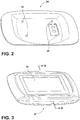
- the remote control system 12 provides a wireless remote control for portable spas and includes a dock 24 ( Fig. 2 ) and a remote control 25 ( Fig. 3 ).
- the dock 24 is mounted into the spa 11 in a user-convenient location and is used to dock the remote 25 when not in use and to charge a battery in the remote 25.
- the remote 25 can be removed from the dock 24 at any time and used either while in the dock 24 or at any location within the vicinity of the spa 11.
- the remote 25 provides fingertip control of jets, lights, music, and other spa functions while relaxing in the spa 11 without requiring the user to change position.
- the remote 25 of the embodiment is completely waterproof and floatable and will operate while floating in the spa water.
- the dock 24 comprises a communications interface to a central spa controller within the spa 11, a radio for communication with the remote, a wireless power transmitter, and a WiFi module for communication to nearby WiFi devices, such as a smart phone.
- the docking station 24 includes four pegs 26, which mate with corresponding holes on the back side of the remote 25. The holes and pegs are positioned such that the remote 25 may be oriented in a first position where the display 27 can be read by someone in the spa 11 or in a second position where it can be read by someone outside the spa 11.
- the remote 25 comprises a touch screen structure 35 specifically designed for a wet environment, a radio for communication with the dock 24, a battery ( Fig. 8 ) with associated battery management systems, a wireless power receiver, a USB programming input, and a configurable graphic system that allows for flexibility in spa control updates, yet still maintains graphics responsiveness and extended battery life.
- the remote 25 has a concentrically layered structure including a polyester layer 31, an adhesive layer 33, a touch screen structure 35, a touch screen adhesive ring 37, an optical adhesive layer 39, an LCD (liquid crystal display) 41, a polyester bead seal 43, a top housing 45, a main seal 47, a PCB (printed circuit board) assembly 49, a bottom housing 51, and a battery pack assembly 53.
- Additional componentry includes a light pipe 55, a pressure vent 57, a test plug 59 and an FCC label 61.
- the top polyester layer 31 is used to provide a flexible touch layer and for waterproofing.
- the layer 31 extends out beyond all other layers for bonding as described below.
- the back of the polyester layer 31 may be printed with various screen-print inks/graphics around the perimeter of the touch area.
- the adhesive seal layer 33 bonds the bottom side of top polyester layer 31 around the perimeter of the plastic housing 45 to the tread (horizontal) portion of a first step 32 ( Fig. 6 ) of the remote control body. This bond and seal prevents water from reaching the inner touch screen structure 35 or its adhesives.
- the adhesive seal layer 33 is water proof and chemical resistant, and in one embodiment may comprise 3M VHBTM double sided tape.
- An optional application of water repellent material, such as a hydrophobic nano-coating, may be made to the outer edge 34 ( Fig. 6 ) of the adhesive 33 to provide additional protection.
- Fig. 7 illustrates a touch sensing structure 35 comprising a clear electrically conductive layer 36 applied to the bottom side of the top polyester layer 31 and a clear electrically conductive layer 40 applied to the top of a polycarbonate substrate layer 42.
- a plurality of spacer dots 38 define a space which separates the conductive layers 36, 40.
- An adhesive bond is made around the perimeter of the touch screen area by adhesive 30 in order to bond the bottom of the top polyester layer 31 to the top of the polycarbonate substrate layer 42, while holding the spacer layer in place.
- the touch screen is a 4-wire resistive touch screen where the conductive layers 36, 40 may be, for example, ITO (indium tin oxide).
- ITO indium tin oxide
- the polyester layer 31 When a person touches the polyester layer 31, it deflects, causing the two ITO layers 36, 40 to make an electrical connection. Since the ITO layers 36, 40 are electrically resistive, the position of the touch can be determined by a resistance reading taken for both X and Y coordinates, as known to those skilled in the art.
- the touch sensing area provided by the touch sensing structure 35 is smaller than the top polyester layer 31 such that the touch sensing adhesive 30 ( Fig. 7 ) is inside the water seal of the adhesive seal layer 33. It is important that the touch sensing adhesive 30 is not exposed to water, as otherwise spa water could eventually seep in between the touch layers 36, 40, causing failure of the touch sensing.
- the polyester layer 31 and its adhesive seal layer 33 larger and protective of the touch sensing adhesive 30, the touch sensing is rendered tolerant to the spa water environment.
- the top polyester layer 31 as both a water proofing layer, and the top of the touch sensing system, the sensitivity of the touch sensing function is greatly enhanced.
- the polycarbonate substrate layer 42 is smaller than the top polyester layer 31 to allow for perimeter sealing, but is larger than the LCD color display 41 below.
- the polycarbonate substrate layer 42 is used to provide mechanical support for the entire assembly, to provide rigid backing support for the touch sensing structure 35, to provide the surface on which the lower layer 40 of electrically conductive touch sensing material is applied, and to provide mechanical mounting for the LCD color screen 41.
- polycarbonate is the preferred material in one embodiment, other substrate materials may also be used, such as acrylic, glass, etc. Polycarbonate provides excellent optical clarity, rigidity, and tolerates dropping.
- a second adhesive support layer 37 is bonded between the polycarbonate layer 42 and the tread of a second step 50 in the plastic housing 45 of the remote control body. This layer 37 is centered within the adhesive seal layer 33 and the first step 32 in the plastic housing 45.
- the optically clear adhesive (OCA) layer 39 bonds the LCD 41 to the bottom side of the polycarbonate layer 42.
- This adhesive 39 covers the entire viewable area of the LCD 41 to eliminate air gaps and the possibility of condensation on the surface of the LCD 41 which would cause image distortions.
- an edge adhesive system could be employed, but will result in a small air gap and potential for condensation on the LCD screen surface.
- the LCD color display 41 is in turn bonded to the bottom of the assembly via another layer 52 of optically clear adhesive.
- a spa remote control in order for a spa remote control to be allowed to be positioned in its charging dock 24 either facing into or out of the spa 11, depending on where the user is accessing it, and to enable the spa remote 25 to float evenly in the water, all weight is centered horizontally, and is evenly distributed vertically so that the device will float consistently.
- a wireless power transfer scheme is employed. To allow charging in either direction of placement in the dock 24, both the power transmit coil in the dock 24, and the power receive coil in the remote 25 are centered horizontally in each respective device. At the same time the rechargeable battery pack 53 is also placed in the center horizontally within the remote 25 so that its weight is centered.
- the spa remote 25 employs a battery assembly (battery pack) 53 which contains a power receiving coil 69, a rechargeable battery 65, a female connector 68, and a temperature sensor located on the small PCB inside the battery pack.
- the temperature sensor is contained within the battery assembly 53 to allow for proper charge management of the battery 65.
- the battery assembly 53 has a perimeter water seal 63 such that all inner components of the assembly 53 are protected from water when installed in the spa remote 25.
- the power receiving coil 69 is placed on the bottom of the battery assembly 53 so that it can pick up magnetic fields from the dock power transmit coil and is also placed in the center of the pack for proper weight centering.
- the rechargeable battery 65 is also centered and placed directly on top of the power receiving coil 69, also for weight centering.
- the electrical interface via connector 66 to the primary electronics of the PCB assembly 49 within the spa remote 25 consists of two coil connections, two battery connections, and two temperature sense connections.
- the two temperature sense connections are also shared by two USB external programming data lines for software updates via the battery connector when the battery assembly 53 is removed.
- the remote 25 uses intelligent charging. Thus, when placed in the dock 24, power from the dock 24 is used to charge the battery 65 if charge is needed. When removed from the dock 24, the remote 25 runs on battery power and tracks usage times to establish typical patterns and anticipate how long the remote 25 is used away from the dock 24 to ensure proper charge.
- This charge algorithm is to extend the battery longevity by performing fewer charge cycles, while at the same time ensuring good run times out of the dock 24 based on usage history.
- the charge algorithm also limits the maximum charge voltage of the battery 65 to about 70%, which at typical spa environment temperatures will also extend battery longevity. Lithium-ion battery life is shortened if held at full charge at 100° F temperature. It is also shortened if allowed to discharge too deeply and if always re-charged whenever placed in the charger. It is ideal to leave the battery 65 in the 30 to 70% charge range at moderate temperatures.
- the top and bottom halves 45, 51 of the remote's plastic housing are sealed around their perimeter using a primary and secondary seal system.
- the primary seal is the "gland" seal 47, where the seal is made horizontally by compressing a relatively soft gasket material between a vertical wall 56 ( Fig. 5 ) protruding down from the top half 45 of the top housing 45 and a mating vertical wall 56a protruding up from the bottom half housing 51.
- a relatively soft gasket material between two rigid walls 56, 56a, very little static pressure is needed in the vertical direction. Therefore, the fasteners 58 that hold the top and bottom together require very little constant tension to maintain the seal, in comparison to a compression seal that relies on the constant tension.
- the secondary seal is a soft gel material 60 embedded in a channel in the top housing 45.
- the top edge of the vertical wall 56a protruding up from the bottom housing protrudes into the gel 60 with slight compression and some displacement of gel 60 to create a secondary seal around the full perimeter of the mating parts 45, 51.
- top and bottom housings 45, 51 are held together with plastic snaps 64, 66 ( Fig. 5 ) molded into the housings, as well as threaded screw fasteners 58 ( Fig. 4 ).
- two screws 58 are inserted through the bottom housing 51 via the battery cavity and then thread into the bottom of the top housing 45.
- Either one or both types of fasteners can be utilized in various embodiments.
- the overall system provides the option of allowing the device to be opened for service and re-work if necessary, as opposed to seal systems that employ permanent adhesives.
- the LCD 41 and touch panel are assembled to form a subassembly ( Figs. 9 , 10 ) consisting of the following layers top to bottom: a) the polyester layer 31, whose rectangular dimension fits into the largest step 32 of the top housing nest, with perimeter adhesive tape 33 for later bonding to the housing 45; b) a touch screen structure 35 affixed to the rear of the polyester layer 31 and on top of the clear polycarbonate layer 42; c) the clear polycarbonate layer 42, whose rectangular dimension fits into the second step 50 in the top housing 45, with a second layer of adhesive tape 37 around its perimeter; d) clear optical bonding adhesive 39 adhered to the back of the polycarbonate layer 42 and to the top of the LCD module 41; and e) the LCD module 41, whose rectangular dimension fits within the smallest step 50 of the top housing nest.
- the perimeter adhesive tape 33 attached to the polyester layer 31 forms a primary water proof seal, and the larger size of the polyester layer 31 prevents the touch screen structure 35 from being exposed to water, as noted above.
- the polycarbonate layer 42 is then attached to the second step 48 via the second layer of adhesive tape 37 for mechanical strength, providing mechanical support for both the polyester layer 31 and the LCD module 41.
- the LCD module 41 is bonded to the back of the polycarbonate layer 42 and does not rest on any of the top housing steps, so it is suspended from the rear of the polycarbonate layer 42, helping protect the LCD glass from breakage.
- the LCD/touchscreen sub-assembly (LCD display, polycarbonate layer touch screen, and top polyester layer) is first assembled into the stepped nested housing cavity and bonded to the top housing 45 via the adhesive tape layers 33, 37.
- the circuit board (PCB) assembly 49 is mounted on the topside of the bottom housing 51.
- the circuit board assembly 49 is positioned by two pegs or bosses and is attached by screws at each of its four corners.
- a flexible electronic connector 50 ( Fig. 5 ) passes through an opening in the stepped housing cavity and into the circuit board cavity and then attaches to the circuit board assembly 49.
- the bottom housing 51 is attached by screws to the top housing 45.
- a waterproof seal between the top and bottom covers is created by a main seal, which is a "gland seal,” which seals by sideways pressure or squeezing, rather than by vertical pressure.
- a "Gore" vent 57 is also provided to eliminate pressure differentials, e.g. for altitude compensation.
- a battery 65 is installed in the rectangular battery housing 53, which is closed by a rectangular cover or "header” 61.
- the closed battery housing 53 then mounts into a rectangular receptacle formed in the underside of the lower housing 51.
- Location pins in the receptacle guide the positioning of the battery housing assembly 59 so that six vertical conductor pins 66 ( Fig. 4 ) are guided through holes in the battery housing cover to properly connect with the battery 65 and inductive charge coil 69.
- the battery pack has its own gland seal 63 for waterproofing, and the battery 65 and coil 69 are centered to promote even floating.
- the top polyester layer 31 and the double sided adhesive tape layer 33 have concentric holes 101 ( Fig. 4 ) formed therein, which conduct ambient light to the light pipe 55, which then conducts the light to a light sensing circuit on the PCB 49.
- the ambient light is used to automatically adjust the back light of the LCD 41 for user comfort and battery power savings.
- the remote control device 25 communicates wirelessly with spa-based control circuitry comprising a radio, e.g. by using an IEEE 802.15.4 or other suitable protocol.
- the remote control 25 communicates commands to/from the spa 11, causing various spa actions.
- the remote's electronics comprises a microprocessor, a graphics sub-system 227 ( Fig. 14 ) to drive the LCD 41, a non-volatile graphics memory to store graphic images, a battery charge circuit controlled by the microprocessor software to restrict charging and extend battery life, and touch screen interface circuitry and software, all of which may be located on PCB 49 in one embodiment.
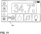
- the remote 25 employs a relatively large color LCD 41 with a full graphical user interface illustrated in Fig. 11 that works with the touch screen.
- This arrangement creates a very user friendly interface that is far less dependent on language and therefore makes the product more easily useable throughout the world.
- the device electronics and processing power must be restrained in order to provide excellent battery life, lower cost to fit the market, and controls-grade reliability.
- the remote 25 is designed to be a slave device of the spa control 190, which allows software and user-interfaces to be easily upgraded via the spa control and does not require full-reprogramming of the remote 25 itself.
- the actual graphic images reside in non-volatile memory in the remote 25.
- the spa control 190 then issues a series of commands to use these graphics to construct the screens on the remote 25.
- the position information is sent to the spa control 190 which has logic to direct new actions on the remote 25 as well as taking actions within the spa 11, as appropriate. For example, touching the JETS icon 105 ( Fig. 11 ) sends its X-Y coordinates to the spa control 190, which, in turn, turns on the jet pumps, and sends commands to the remote 25 to draw the graphics for the JETS screen.
- graphics must be moved from non-volatile memory to the graphics output memory for displaying them.
- the user-interface would suffer significantly if every image had to be loaded from non-volatile memory every time something changed because it would take multiple seconds for each action, making the user-interface unworkable.
- a memory system is constructed as part of a system which responds to spa control commands to create various displays.
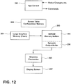
- An embodiment of such a memory system is shown in Fig. 12 and includes a screen configuration table 200, a large graphics memory 201, and SDRAM 203 comprising memory buffers 204 and a dynamic output buffer 206.
- the SDRAM 203 communicates with graphics electronics 205, which causes display of desired images on the display screen 207.
- the software employed in the remote system 12 takes steps to minimize delays and to create a very responsive dynamic user-interface.
- the remote 25 contains a screen configuration table memory 200. This memory 200 is initialized and updated by the spa control via a series of commands to create a screen. Once a screen has been created, the next time the remote 25 must display that screen, it draws the screen based on the contents of the configuration memory 200. The screen draw time is significantly shorter than a new screen construction, although the spa control can over-write this memory 200 at any time as required.
- the configuration memory 200 is non-volatile so that it is immediately available after a power cycle/battery change.
- the remote 25 also contains the large graphics memory 201 in non-volatile "flash” memory and the high speed "SDRAM" volatile memory 203 whose contents can be directly and immediately displayed by the graphic electronics 205.
- the remote 25 On power-up from battery insertion or placement into the dock, step 209 of Fig. 13 , the remote 25 immediately starts pre-loading screens from the flash memory 201 into the SDRAM memory buffers 204 based on the configuration memory 200 (step 211).
- the screens loaded are the ones most used. This preload can take up to 15 to 20 seconds.
- the graphics system also has a dynamic output screen buffer 206 in SDRAM 203.
- the spa control 190 When a new screen is to be drawn, the spa control 190 first instructs the remote 25 to display an image from one of the SDRAM memory buffers 204, if available, step 215. Then, the spa controller 190 sends commands to construct a completely up-to-date version of the same image, but with the current spa status (such as jet pumps being "on") in the dynamic buffer 206 (step 217). Once this new image is prepared, the graphic system is instructed to instantaneously switch the image from the SDRAM memory buffer 204 to the new image stored in the dynamic output buffer 206, step 219. To build and maintain the configuration memory 200, the command strings are updated to the non-volatile memory on each command if there is a change, step 221.
- commands are transmitted wirelessly from the spa controller 190 to a wireless transceiver 223, and then to a microprocessor 225, as shown in Fig. 14 .
- the microprocessor 225 then executes the various commands issued by the spa control 190 through appropriate control of the various memories and electronics illustrated in Fig. 12 .
- the SDRAM 203 requires power to retain the graphic images. While the remote 25 is in the dock charging station, power is supplied from the dock. However, if the remote 25 is removed from the dock, the battery 65 must supply all power. It is desirable that the remote 25 wake up immediately with no delays to load graphics, so the battery 65 must power the SDRAM 203 for expected periods of time when the remote is removed from the dock. At the same time, it is desirable to not over-discharge the battery 65.
- a power management scheme is implemented that enhances the user's graphical experience.
- Graphics images are loaded upon power up.
- Graphics images are retained in SDRAM 203 at all times when powered from the dock.
- Graphics images are retained on battery power if not in the dock at full power for short periods of time while the user is controlling the spa (several minutes per session).
- Graphics images are also retained under battery power in a "doze" mode for 1 to 2 days (expected) by turning off all electronics except the SDRAM 203 in an ultra-low power mode.
- the SDRAM 203 is also shut off and the entire system goes into deep sleep in order to preserve some battery power and avoid "over-discharge". Re-power after deep sleep is identical to a cold power-up and all graphics images must be re-loaded, based on the configuration memory described above.
- Embodiments of the touch screen described herein may thus provide a highly sensitive touch screen that works in water, having a smooth front surface appearance, a bright intuitive display, and compatibility with the harsh spa environment.
- the touch screen sub-assembly of embodiments is also unique in that it allows full touch screen control of the spa 11 even while operating in the water, yet does not require a front bezel for water sealing, maintains excellent sensitivity to touch, and has a large full color screen.
Landscapes
- Health & Medical Sciences (AREA)
- Public Health (AREA)
- Physics & Mathematics (AREA)
- General Health & Medical Sciences (AREA)
- Veterinary Medicine (AREA)
- Animal Behavior & Ethology (AREA)
- Life Sciences & Earth Sciences (AREA)
- Rehabilitation Therapy (AREA)
- Physical Education & Sports Medicine (AREA)
- Epidemiology (AREA)
- Pain & Pain Management (AREA)
- Nonlinear Science (AREA)
- Chemical & Material Sciences (AREA)
- Crystallography & Structural Chemistry (AREA)
- Optics & Photonics (AREA)
- General Physics & Mathematics (AREA)
- Mathematical Physics (AREA)
- Selective Calling Equipment (AREA)
- Casings For Electric Apparatus (AREA)
- Battery Mounting, Suspending (AREA)
Description
- The subject disclosure relates to spas, tubs, and the like and more particularly to a dockable remote control for enabling a spa user to remotely control various spa functions.
-
JP-A-2011053745 -
US-A-2008246741 describes an input device that includes an input panel, a cover member that is provided with a housing portion, in which the input panel is housed, and a film member that is disposed over a main surface of the input panel provided in the housing portion and a main surface of the cover member. -
EP-A-1860531 describes a display device equipped with a touch panel that includes a device chassis provided with an opening section, a display panel having a display surface disposed to be accessible through the opening section, a touch panel disposed on the display surface of the display panel and capable at least of selecting a function displayed on the display surface in response to a pressing operation on the touch panel, and a surface sheet for covering the touch panel on the opposite side to the display panel, and closing the opening section to form substantially the same surface with the device chassis, wherein a reinforcing area for improving resistivity against pressing force applied from the outside is provided in a predetermined range of the surface sheet. - According an aspect of the present invention, there is provided a waterproof floatable remote control comprising a top housing comprising a first upper step leading to a second lower step; a top polyester layer; a first adhesive layer located about the perimeter of an underside of the top polyester layer and attaching the top polyester layer to a tread portion of the first upper step; a clear polycarbonate layer having a sidewall lying adjacent a riser portion of the first upper step and having a rectangular top surface; a resistive touch screen structure comprising an upper conductive layer located on a backside of the top polyester layer and spaced apart from a lower conductive layer located on a top surface of the clear polycarbonate layer; a perimeter adhesive formed around a perimeter of the touch screen structure and bonding the backside of the top polyester layer to the top surface of the clear polycarbonate layer; a second adhesive layer fastening a bottom surface of the polycarbonate layer to a tread portion of the second lower step; an LCD module positioned adjacent a riser portion of the second lower step; and a clear optical bonding adhesive adhering the back of the polycarbonate to the top of the LCD module; wherein the first adhesive layer on the underside of the top polyester layer forms a primary water proof seal and wherein the top polyester layer has a width greater than that of a width of the touch screen structure thereby preventing the touch screen structure from being exposed to water; and wherein the second layer of adhesive provides mechanical support for both the polyester layer and the LCD module.
- In embodiments, the remote control further comprises a bottom housing configured to mate with and attach to the top housing and having a receptacle therein; a battery assembly mounted in the receptacle and comprising a rectangular housing, a rechargeable battery comprising a battery mounted in said housing, and a power receiving coil mounted in the housing beneath the battery for charging the rechargeable battery; wherein the rectangular housing of the battery assembly comprises a bottom part mating with a top part, and a watertight gland seal between the bottom part and the receptacle; and wherein the battery assembly and the power receiving coil are centered within the bottom housing to promote even floating of the remote control.
- In embodiments, the remote control further comprises a circuit board assembly mounted on a topside of the bottom housing. Preferably, the circuit board assembly is positioned by two pegs or bosses and is attached by screws at each of four corners. More preferably, a flexible electronic connector passes from the touch screen structure through an opening in a stepped housing cavity, then into a circuit board cavity, and then attaches to the circuit board assembly.
- In embodiments, the layers are concentric.
- In embodiments, the remote control is further configured to removably mount to a docking station fixedly located in a spa. Preferably, said docking station comprises a communications interface to a central spa controller within the spa, a radio for communication with the remote, a wireless power transmitter, and a WiFi module for communication to nearby WiFi devices, such as a smart phone.
- In embodiments, a central cavity is defined by the riser portion of the second step.
- In embodiments, a gland seal is positioned between respective vertical walls of the top and bottom housings and a secondary seal is formed by a soft gel material embedded in a channel in the top housing into which protrudes the vertical wall of the bottom housing. Preferably, the top and bottom housings are held together with first and second plastic snaps molded into the housings, as well as by threaded fasteners.
- In embodiments, the remote control further comprises a graphics display system comprising a screen configuration table memory, a graphics memory, an SDRAM, and graphics electronics controlling image display on a display screen, the system being configured to preload screens from the flash memory to SDRAM upon system power-up based on the screen configuration table memory; respond to a first command from a spa controller to draw a first new screen by sending image data from a memory buffer portion of SDRAM to the graphics electronics to cause display of the image represented by the image data; respond to commands from the spa controller to update the first new screen image by constructing a new update image in a dynamic buffer portion of SDRAM; and instantaneously cause display of the new image stored in the dynamic buffer to replace the image originally presented from the SDRAM memory buffer. Preferably, the system is further configured to update the screen configuration table memory to reflect the new image being displayed. Preferably, the screens which are preloaded during power-up comprise those screens which are most frequently used. Preferably, the commands from the spa controller are received over a wireless link comprising a wireless transceiver located in said remote control. Preferably, the graphics memory comprises flash memory.
-
Fig. 1 is a perspective view of an portable spa; -
Fig. 2 is a perspective view of a remote control docking station; -
Fig. 3 is a perspective view of a remote control; -
Fig. 4 is an exploded perspective view of the remote control ofFig. 3 ; -
Fig. 5 is a cross-sectional view of the remote control taken at V-V ofFig. 3 ; -
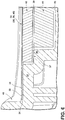
Fig. 6 is a fragmentary schematic side sectional view of the structure of the remote control ofFig. 3 ; -
Fig. 7 is a fragmentary side sectional view of touch sensing structure employed in the remote control ofFig. 3 ; -
Fig. 8 is an exploded perspective view of the battery assembly of the remote control ofFig. 3 ; -
Fig. 9 is a top view of the touch panel assembly of the remote control ofFig. 3 ; -
Fig. 10 is a bottom view of the touch panel assembly ofFig. 9 ; -
Fig. 11 is a front view of a graphical interface for the remote control ofFig. 3 ; -
Fig. 12 is a schematic block diagram of a memory system of a remote control; -
Fig. 13 is a flow diagram illustrating a method of display screen image generation; -
Fig. 14 is a block diagram illustrating one embodiment of hardware for use in implementing the method ofFig. 13 . -
Fig. 1 illustrates aportable spa 11 having aspa shell 13,side panels corner pieces spa shell 11 has a generallyrectangular rim 14 about its upper periphery and includes various features such as jets, e.g. 16, 18, afilter compartment 20 and aremote control system 12. - The
remote control system 12 provides a wireless remote control for portable spas and includes a dock 24 (Fig. 2 ) and a remote control 25 (Fig. 3 ). Thedock 24 is mounted into thespa 11 in a user-convenient location and is used to dock the remote 25 when not in use and to charge a battery in the remote 25. The remote 25 can be removed from thedock 24 at any time and used either while in thedock 24 or at any location within the vicinity of thespa 11. The remote 25 provides fingertip control of jets, lights, music, and other spa functions while relaxing in thespa 11 without requiring the user to change position. The remote 25 of the embodiment is completely waterproof and floatable and will operate while floating in the spa water. - The
dock 24 comprises a communications interface to a central spa controller within thespa 11, a radio for communication with the remote, a wireless power transmitter, and a WiFi module for communication to nearby WiFi devices, such as a smart phone. Thedocking station 24 includes fourpegs 26, which mate with corresponding holes on the back side of the remote 25. The holes and pegs are positioned such that the remote 25 may be oriented in a first position where the display 27 can be read by someone in thespa 11 or in a second position where it can be read by someone outside thespa 11. - In one embodiment, the remote 25 comprises a
touch screen structure 35 specifically designed for a wet environment, a radio for communication with thedock 24, a battery (Fig. 8 ) with associated battery management systems, a wireless power receiver, a USB programming input, and a configurable graphic system that allows for flexibility in spa control updates, yet still maintains graphics responsiveness and extended battery life. - The construction of an embodiment of the
remote control 25 is illustrated inFigs. 4-8 . As shown in the assembly view ofFig. 4 , theremote 25 has a concentrically layered structure including apolyester layer 31, anadhesive layer 33, atouch screen structure 35, a touch screenadhesive ring 37, an opticaladhesive layer 39, an LCD (liquid crystal display) 41, apolyester bead seal 43, atop housing 45, amain seal 47, a PCB (printed circuit board)assembly 49, abottom housing 51, and abattery pack assembly 53. Additional componentry includes alight pipe 55, apressure vent 57, atest plug 59 and an FCClabel 61. - In the embodiment, the
top polyester layer 31 is used to provide a flexible touch layer and for waterproofing. Thelayer 31 extends out beyond all other layers for bonding as described below. In one embodiment, the back of thepolyester layer 31 may be printed with various screen-print inks/graphics around the perimeter of the touch area. - The
adhesive seal layer 33 bonds the bottom side oftop polyester layer 31 around the perimeter of theplastic housing 45 to the tread (horizontal) portion of a first step 32 (Fig. 6 ) of the remote control body. This bond and seal prevents water from reaching the innertouch screen structure 35 or its adhesives. Theadhesive seal layer 33 is water proof and chemical resistant, and in one embodiment may comprise 3M VHB™ double sided tape. An optional application of water repellent material, such as a hydrophobic nano-coating, may be made to the outer edge 34 (Fig. 6 ) of theadhesive 33 to provide additional protection. -
Fig. 7 illustrates atouch sensing structure 35 comprising a clear electricallyconductive layer 36 applied to the bottom side of thetop polyester layer 31 and a clear electricallyconductive layer 40 applied to the top of apolycarbonate substrate layer 42. A plurality ofspacer dots 38 define a space which separates theconductive layers top polyester layer 31 to the top of thepolycarbonate substrate layer 42, while holding the spacer layer in place. - In an embodiment, the touch screen is a 4-wire resistive touch screen where the
conductive layers polyester layer 31, it deflects, causing the two ITO layers 36, 40 to make an electrical connection. Since the ITO layers 36, 40 are electrically resistive, the position of the touch can be determined by a resistance reading taken for both X and Y coordinates, as known to those skilled in the art. - As seen in
Figs. 5 and6 , the touch sensing area provided by thetouch sensing structure 35 is smaller than thetop polyester layer 31 such that the touch sensing adhesive 30 (Fig. 7 ) is inside the water seal of theadhesive seal layer 33. It is important that thetouch sensing adhesive 30 is not exposed to water, as otherwise spa water could eventually seep in between the touch layers 36, 40, causing failure of the touch sensing. By making thepolyester layer 31 and itsadhesive seal layer 33 larger and protective of thetouch sensing adhesive 30, the touch sensing is rendered tolerant to the spa water environment. By using thetop polyester layer 31 as both a water proofing layer, and the top of the touch sensing system, the sensitivity of the touch sensing function is greatly enhanced. - As further seen in
Figs. 5 and6 , thepolycarbonate substrate layer 42 is smaller than thetop polyester layer 31 to allow for perimeter sealing, but is larger than theLCD color display 41 below. Thepolycarbonate substrate layer 42 is used to provide mechanical support for the entire assembly, to provide rigid backing support for thetouch sensing structure 35, to provide the surface on which thelower layer 40 of electrically conductive touch sensing material is applied, and to provide mechanical mounting for theLCD color screen 41. Although polycarbonate is the preferred material in one embodiment, other substrate materials may also be used, such as acrylic, glass, etc. Polycarbonate provides excellent optical clarity, rigidity, and tolerates dropping. - A second
adhesive support layer 37 is bonded between thepolycarbonate layer 42 and the tread of asecond step 50 in theplastic housing 45 of the remote control body. Thislayer 37 is centered within theadhesive seal layer 33 and thefirst step 32 in theplastic housing 45. - The optically clear adhesive (OCA) layer 39 (
Fig. 6 ) bonds theLCD 41 to the bottom side of thepolycarbonate layer 42. This adhesive 39 covers the entire viewable area of theLCD 41 to eliminate air gaps and the possibility of condensation on the surface of theLCD 41 which would cause image distortions. Alternatively, an edge adhesive system could be employed, but will result in a small air gap and potential for condensation on the LCD screen surface. TheLCD color display 41 is in turn bonded to the bottom of the assembly via anotherlayer 52 of optically clear adhesive. - In the embodiment, in order for a spa remote control to be allowed to be positioned in its charging
dock 24 either facing into or out of thespa 11, depending on where the user is accessing it, and to enable the spa remote 25 to float evenly in the water, all weight is centered horizontally, and is evenly distributed vertically so that the device will float consistently. To allow reliable charging in the spa environment, a wireless power transfer scheme is employed. To allow charging in either direction of placement in thedock 24, both the power transmit coil in thedock 24, and the power receive coil in the remote 25 are centered horizontally in each respective device. At the same time therechargeable battery pack 53 is also placed in the center horizontally within the remote 25 so that its weight is centered. - As illustrated in
Fig. 8 , to allow for occasional battery replacement, thespa remote 25 employs a battery assembly (battery pack) 53 which contains apower receiving coil 69, arechargeable battery 65, a female connector 68, and a temperature sensor located on the small PCB inside the battery pack. The temperature sensor is contained within thebattery assembly 53 to allow for proper charge management of thebattery 65. Thebattery assembly 53 has aperimeter water seal 63 such that all inner components of theassembly 53 are protected from water when installed in thespa remote 25. Thepower receiving coil 69 is placed on the bottom of thebattery assembly 53 so that it can pick up magnetic fields from the dock power transmit coil and is also placed in the center of the pack for proper weight centering. Therechargeable battery 65 is also centered and placed directly on top of thepower receiving coil 69, also for weight centering. - In an embodiment, the electrical interface via
connector 66 to the primary electronics of thePCB assembly 49 within thespa remote 25 consists of two coil connections, two battery connections, and two temperature sense connections. The two temperature sense connections are also shared by two USB external programming data lines for software updates via the battery connector when thebattery assembly 53 is removed. - In an embodiment, the remote 25 uses intelligent charging. Thus, when placed in the
dock 24, power from thedock 24 is used to charge thebattery 65 if charge is needed. When removed from thedock 24, the remote 25 runs on battery power and tracks usage times to establish typical patterns and anticipate how long the remote 25 is used away from thedock 24 to ensure proper charge. - While in battery mode (away from the dock), the remote's software counts the active time (not dozing or sleeping). When placed back in the
dock 24, start of charge is determined by looking at the recent usage times and the battery voltage. A charge cycle will be started at a higher battery voltage/charge level if typical recent usage away from thedock 24 is longer, and the charge cycle will be started at a lower battery voltage/lower charge level if it is expected that the next usage will require less power/shorter usage. - The purpose of this charge algorithm is to extend the battery longevity by performing fewer charge cycles, while at the same time ensuring good run times out of the
dock 24 based on usage history. The charge algorithm also limits the maximum charge voltage of thebattery 65 to about 70%, which at typical spa environment temperatures will also extend battery longevity. Lithium-ion battery life is shortened if held at full charge at 100° F temperature. It is also shortened if allowed to discharge too deeply and if always re-charged whenever placed in the charger. It is ideal to leave thebattery 65 in the 30 to 70% charge range at moderate temperatures. - In one embodiment, the top and
bottom halves seal 47, where the seal is made horizontally by compressing a relatively soft gasket material between a vertical wall 56 (Fig. 5 ) protruding down from thetop half 45 of thetop housing 45 and a matingvertical wall 56a protruding up from thebottom half housing 51. By sealing horizontally between tworigid walls fasteners 58 that hold the top and bottom together require very little constant tension to maintain the seal, in comparison to a compression seal that relies on the constant tension. - The secondary seal is a
soft gel material 60 embedded in a channel in thetop housing 45. The top edge of thevertical wall 56a protruding up from the bottom housing protrudes into thegel 60 with slight compression and some displacement ofgel 60 to create a secondary seal around the full perimeter of themating parts - The top and
bottom housings plastic snaps 64, 66 (Fig. 5 ) molded into the housings, as well as threaded screw fasteners 58 (Fig. 4 ). In one embodiment (Fig. 4 ), twoscrews 58 are inserted through thebottom housing 51 via the battery cavity and then thread into the bottom of thetop housing 45. Either one or both types of fasteners can be utilized in various embodiments. The overall system provides the option of allowing the device to be opened for service and re-work if necessary, as opposed to seal systems that employ permanent adhesives. - According to one embodiment, the
LCD 41 and touch panel are assembled to form a subassembly (Figs. 9 ,10 ) consisting of the following layers top to bottom: a) thepolyester layer 31, whose rectangular dimension fits into thelargest step 32 of the top housing nest, with perimeteradhesive tape 33 for later bonding to thehousing 45; b) atouch screen structure 35 affixed to the rear of thepolyester layer 31 and on top of theclear polycarbonate layer 42; c) theclear polycarbonate layer 42, whose rectangular dimension fits into thesecond step 50 in thetop housing 45, with a second layer ofadhesive tape 37 around its perimeter; d) clearoptical bonding adhesive 39 adhered to the back of thepolycarbonate layer 42 and to the top of theLCD module 41; and e) theLCD module 41, whose rectangular dimension fits within thesmallest step 50 of the top housing nest. - When the LCD/touch panel subassembly just described is placed into the stepped nest of the
top housing 45, the perimeteradhesive tape 33 attached to thepolyester layer 31 forms a primary water proof seal, and the larger size of thepolyester layer 31 prevents thetouch screen structure 35 from being exposed to water, as noted above. Thepolycarbonate layer 42 is then attached to the second step 48 via the second layer ofadhesive tape 37 for mechanical strength, providing mechanical support for both thepolyester layer 31 and theLCD module 41. TheLCD module 41 is bonded to the back of thepolycarbonate layer 42 and does not rest on any of the top housing steps, so it is suspended from the rear of thepolycarbonate layer 42, helping protect the LCD glass from breakage. - In assembly, the LCD/touchscreen sub-assembly (LCD display, polycarbonate layer touch screen, and top polyester layer) is first assembled into the stepped nested housing cavity and bonded to the
top housing 45 via the adhesive tape layers 33, 37. The circuit board (PCB)assembly 49 is mounted on the topside of thebottom housing 51. In one embodiment, thecircuit board assembly 49 is positioned by two pegs or bosses and is attached by screws at each of its four corners. A flexible electronic connector 50 (Fig. 5 ) passes through an opening in the stepped housing cavity and into the circuit board cavity and then attaches to thecircuit board assembly 49. - The
bottom housing 51 is attached by screws to thetop housing 45. As noted above, a waterproof seal between the top and bottom covers is created by a main seal, which is a "gland seal," which seals by sideways pressure or squeezing, rather than by vertical pressure. A "Gore"vent 57 is also provided to eliminate pressure differentials, e.g. for altitude compensation. - As noted above, a
battery 65 is installed in therectangular battery housing 53, which is closed by a rectangular cover or "header" 61. Theclosed battery housing 53 then mounts into a rectangular receptacle formed in the underside of thelower housing 51. Location pins in the receptacle guide the positioning of thebattery housing assembly 59 so that six vertical conductor pins 66 (Fig. 4 ) are guided through holes in the battery housing cover to properly connect with thebattery 65 andinductive charge coil 69. The battery pack has itsown gland seal 63 for waterproofing, and thebattery 65 andcoil 69 are centered to promote even floating. - In one embodiment, the
top polyester layer 31 and the double sidedadhesive tape layer 33 have concentric holes 101 (Fig. 4 ) formed therein, which conduct ambient light to thelight pipe 55, which then conducts the light to a light sensing circuit on thePCB 49. The ambient light is used to automatically adjust the back light of theLCD 41 for user comfort and battery power savings. - In one embodiment, the
remote control device 25 communicates wirelessly with spa-based control circuitry comprising a radio, e.g. by using an IEEE 802.15.4 or other suitable protocol. Theremote control 25 communicates commands to/from thespa 11, causing various spa actions. The remote's electronics comprises a microprocessor, a graphics sub-system 227 (Fig. 14 ) to drive theLCD 41, a non-volatile graphics memory to store graphic images, a battery charge circuit controlled by the microprocessor software to restrict charging and extend battery life, and touch screen interface circuitry and software, all of which may be located onPCB 49 in one embodiment. - In an embodiment, the remote 25 employs a relatively
large color LCD 41 with a full graphical user interface illustrated inFig. 11 that works with the touch screen. This arrangement creates a very user friendly interface that is far less dependent on language and therefore makes the product more easily useable throughout the world. At the same time, the device electronics and processing power must be restrained in order to provide excellent battery life, lower cost to fit the market, and controls-grade reliability. - In one embodiment, the remote 25 is designed to be a slave device of the
spa control 190, which allows software and user-interfaces to be easily upgraded via the spa control and does not require full-reprogramming of the remote 25 itself. In this embodiment, the actual graphic images reside in non-volatile memory in the remote 25. Thespa control 190 then issues a series of commands to use these graphics to construct the screens on the remote 25. When the screen is touched, the position information is sent to thespa control 190 which has logic to direct new actions on the remote 25 as well as taking actions within thespa 11, as appropriate. For example, touching the JETS icon 105 (Fig. 11 ) sends its X-Y coordinates to thespa control 190, which, in turn, turns on the jet pumps, and sends commands to the remote 25 to draw the graphics for the JETS screen. - According to this embodiment, graphics must be moved from non-volatile memory to the graphics output memory for displaying them. The user-interface would suffer significantly if every image had to be loaded from non-volatile memory every time something changed because it would take multiple seconds for each action, making the user-interface unworkable.
- At the same time, significant delays occur if the
spa control 190 must issue multiple commands to create each screen as there may be many details involved. Due to power and reliability considerations, the speed of the radio link with wireless transmitter/receiver of the remote 25 is relatively slow and limits the update speeds, and is not conducive to full image transfers. - Accordingly, a memory system is constructed as part of a system which responds to spa control commands to create various displays. An embodiment of such a memory system is shown in
Fig. 12 and includes a screen configuration table 200, alarge graphics memory 201, andSDRAM 203 comprising memory buffers 204 and adynamic output buffer 206. TheSDRAM 203 communicates withgraphics electronics 205, which causes display of desired images on thedisplay screen 207. - The software employed in the
remote system 12 takes steps to minimize delays and to create a very responsive dynamic user-interface. As noted, the remote 25 contains a screenconfiguration table memory 200. Thismemory 200 is initialized and updated by the spa control via a series of commands to create a screen. Once a screen has been created, the next time the remote 25 must display that screen, it draws the screen based on the contents of theconfiguration memory 200. The screen draw time is significantly shorter than a new screen construction, although the spa control can over-write thismemory 200 at any time as required. Theconfiguration memory 200 is non-volatile so that it is immediately available after a power cycle/battery change. The remote 25 also contains thelarge graphics memory 201 in non-volatile "flash" memory and the high speed "SDRAM"volatile memory 203 whose contents can be directly and immediately displayed by thegraphic electronics 205. - On power-up from battery insertion or placement into the dock, step 209 of
Fig. 13 , the remote 25 immediately starts pre-loading screens from theflash memory 201 into theSDRAM memory buffers 204 based on the configuration memory 200 (step 211). In the embodiment, the screens loaded are the ones most used. This preload can take up to 15 to 20 seconds. The graphics system also has a dynamicoutput screen buffer 206 inSDRAM 203. - When a new screen is to be drawn, the
spa control 190 first instructs the remote 25 to display an image from one of theSDRAM memory buffers 204, if available,step 215. Then, thespa controller 190 sends commands to construct a completely up-to-date version of the same image, but with the current spa status (such as jet pumps being "on") in the dynamic buffer 206 (step 217). Once this new image is prepared, the graphic system is instructed to instantaneously switch the image from theSDRAM memory buffer 204 to the new image stored in thedynamic output buffer 206,step 219. To build and maintain theconfiguration memory 200, the command strings are updated to the non-volatile memory on each command if there is a change,step 221. - In one embodiment, commands are transmitted wirelessly from the
spa controller 190 to awireless transceiver 223, and then to amicroprocessor 225, as shown inFig. 14 . Themicroprocessor 225 then executes the various commands issued by thespa control 190 through appropriate control of the various memories and electronics illustrated inFig. 12 . - The
SDRAM 203 requires power to retain the graphic images. While the remote 25 is in the dock charging station, power is supplied from the dock. However, if the remote 25 is removed from the dock, thebattery 65 must supply all power. It is desirable that the remote 25 wake up immediately with no delays to load graphics, so thebattery 65 must power theSDRAM 203 for expected periods of time when the remote is removed from the dock. At the same time, it is desirable to not over-discharge thebattery 65. - Therefore, a power management scheme is implemented that enhances the user's graphical experience. Graphics images are loaded upon power up. Graphics images are retained in
SDRAM 203 at all times when powered from the dock. Graphics images are retained on battery power if not in the dock at full power for short periods of time while the user is controlling the spa (several minutes per session). Graphics images are also retained under battery power in a "doze" mode for 1 to 2 days (expected) by turning off all electronics except theSDRAM 203 in an ultra-low power mode. After 1-2 days of maintaining the graphics on battery power, theSDRAM 203 is also shut off and the entire system goes into deep sleep in order to preserve some battery power and avoid "over-discharge". Re-power after deep sleep is identical to a cold power-up and all graphics images must be re-loaded, based on the configuration memory described above. - The design of the touch screen of the embodiment allows for normal operation and normal life in the harsh spa environment. Embodiments of the touch screen described herein may thus provide a highly sensitive touch screen that works in water, having a smooth front surface appearance, a bright intuitive display, and compatibility with the harsh spa environment. The touch screen sub-assembly of embodiments is also unique in that it allows full touch screen control of the
spa 11 even while operating in the water, yet does not require a front bezel for water sealing, maintains excellent sensitivity to touch, and has a large full color screen. - Those skilled in the art will appreciate that various adaptations and modifications of the described embodiments can be configured without departing from the scope of the appended claims.
Claims (15)
- A waterproof floatable remote control (25) for a spa comprising:a top housing (45) comprising a first upper step (32) leading to a second lower step (50);a top polyester layer (31);a first adhesive layer (33) located about the perimeter of an underside of the top polyester layer and attaching the top polyester layer to a tread portion of the first upper step (32);a clear polycarbonate layer (42) having a sidewall lying adjacent a riser portion of the first upper step (32) and having a rectangular top surface;a resistive touch screen structure (35) comprising an upper conductive layer (36) located on a backside of the top polyester layer (31) and spaced apart from a lower conductive layer (40) located on a top surface of the clear polycarbonate layer (42);a perimeter adhesive (30) formed around a perimeter of the touch screen structure (35) and bonding the backside of the top polyester layer (31) to the top surface of the clear polycarbonate layer (42);a second adhesive layer (37) fastening a bottom surface of the polycarbonate layer (42) to a tread portion of the second lower step (50);an LCD module (41) positioned adjacent a riser portion of the second lower step (50);a clear optical bonding adhesive (39) adhering the back of the polycarbonate layer (42) to the top of the LCD module (41);wherein the first adhesive layer (33) on the underside of the top polyester layer (31) forms a primary water proof seal and wherein the top polyester layer (31) has a width greater than that of a width of the touch screen structure (35) thereby preventing the touch screen structure (35) from being exposed to water; andwherein the second layer of adhesive (37) provides mechanical support for both the polyester layer (31) and the LCD module (41).
- The remote control of claim 1 further comprising:a bottom housing (51) configured to mate with and attach to said top housing and having a receptacle therein;a battery assembly mounted in said receptacle and comprising:(a) a rectangular housing (53);(b) a rechargeable battery assembly (65) comprising a battery mounted in said housing; and(c) a power receiving coil (69) mounted in said housing beneath said battery assembly for charging said rechargeable battery;wherein the rectangular housing of the battery assembly comprises:a bottom part mating with a top part;a watertight gland seal (63) between said bottom part and said receptacle; andwherein the battery assembly and the power receiving coil are centered within the bottom housing to promote even floating of the remote control.
- The remote control of claim 1 further comprising a circuit board assembly (49) mounted on a topside of the bottom housing.
- The remote control of claim 3 wherein the circuit board assembly is positioned by two pegs or bosses and is attached by screws at each of four corners.
- The remote control of claim 3 wherein a flexible electronic connector (50) passes from the touch screen structure through an opening in a stepped housing cavity, then into a circuit board cavity, and then attaches to the circuit board assembly.
- The remote control of claim 1 wherein the layers are concentric.
- The remote control of claim 1 further configured to removably mount to a docking station (24) fixedly located in a spa.
- The remote control of claim 7 wherein said docking station comprises a communications interface to a central spa controller within the spa, a radio for communication with the remote, a wireless power transmitter, and a WiFi module for communication to nearby WiFi devices, such as a smart phone.
- The remote control of claim 1 wherein a central cavity is defined by the riser portion of the second step.
- The remote control of claim 2 wherein a gland seal is positioned between respective vertical walls (56a) of the top and bottom housings and a secondary seal is formed by a soft gel material (60) embedded in a channel in the top housing into which protrudes the vertical wall of the bottom housing.
- The remote control of claim 10 wherein the top and bottom housings are held together with first and second plastic snaps (64, 66) molded into the housings, as well as by threaded fasteners (58).
- The remote control of claim 1 further comprising a graphics display system (227) comprising a screen configuration table memory, a graphics memory, an SDRAM, and graphics electronics controlling image display on a display screen, the system being configured to:preload screens from the flash memory to SDRAM upon system power-up based on the screen configuration table memory;respond to a first command from a spa controller to draw a first new screen by sending image data from a memory buffer portion of SDRAM to the graphics electronics to cause display of the image represented by the image data;respond to commands from the spa controller to update the first new screen image by constructing a new update image in a dynamic buffer portion of SDRAM; andinstantaneously cause display of the new image stored in the dynamic buffer to replace the image originally presented from the SDRAM memory buffer.
- The remote control of claim 12 wherein the system is further configured to update the screen configuration table memory to reflect the new image being displayed.
- The remote control of claim 12 wherein the screens which are preloaded during power-up comprise those screens which are most frequently used.
- The remote control of claim 12 wherein the commands from the spa controller are received over a wireless link comprising a wireless transceiver located in said remote control.
Applications Claiming Priority (3)
| Application Number | Priority Date | Filing Date | Title |
|---|---|---|---|
| US201461927090P | 2014-01-14 | 2014-01-14 | |
| US14/262,597 US9326912B2 (en) | 2014-01-14 | 2014-04-25 | Dockable remote control for portable spas |
| PCT/US2014/047057 WO2015108566A1 (en) | 2014-01-14 | 2014-07-17 | Dockable remote control for portable spas |
Publications (3)
| Publication Number | Publication Date |
|---|---|
| EP3094223A1 EP3094223A1 (en) | 2016-11-23 |
| EP3094223A4 EP3094223A4 (en) | 2017-12-27 |
| EP3094223B1 true EP3094223B1 (en) | 2019-03-20 |
Family
ID=53520386
Family Applications (1)
| Application Number | Title | Priority Date | Filing Date |
|---|---|---|---|
| EP14878906.8A Active EP3094223B1 (en) | 2014-01-14 | 2014-07-17 | Dockable remote control for portable spas |
Country Status (5)
| Country | Link |
|---|---|
| US (1) | US9326912B2 (en) |
| EP (1) | EP3094223B1 (en) |
| CA (1) | CA2925859C (en) |
| NZ (1) | NZ718504A (en) |
| WO (1) | WO2015108566A1 (en) |
Families Citing this family (19)
| Publication number | Priority date | Publication date | Assignee | Title |
|---|---|---|---|---|
| US8578081B1 (en) | 2007-07-25 | 2013-11-05 | Robert Louis Fils | Docking station for an electronic device |
| US20160175189A1 (en) * | 2013-04-08 | 2016-06-23 | Robert Louis Fils | Method, system and apparatus for communicating with an electronic device and a stereo housing |
| US9680515B2 (en) * | 2014-07-11 | 2017-06-13 | Superior Communications, Inc. | Mobile device case and armband with fluid chamber |
| USD772284S1 (en) | 2014-09-01 | 2016-11-22 | Apple Inc. | Display screen or portion thereof with a set of graphical user interfaces |
| USD842818S1 (en) * | 2015-06-23 | 2019-03-12 | Gecko Alliance Group Inc. | Top-side control panel for bathing unit |
| US20170017315A1 (en) * | 2015-07-14 | 2017-01-19 | Gecko Alliance Group Inc. | Topside control panel for bathing unit system |
| US10660819B2 (en) * | 2015-07-16 | 2020-05-26 | Bestway Inflatables & Material Corp. | Pool pump |
| CN107454788B (en) * | 2017-08-24 | 2022-11-29 | 佛山市汇凯达科技有限公司 | Remote controller with float waterproof function |
| US10925804B2 (en) | 2017-10-04 | 2021-02-23 | Sundance Spas, Inc. | Remote spa control system |
| JP7055038B2 (en) * | 2018-03-07 | 2022-04-15 | セイコーインスツル株式会社 | clock |
| US10615836B1 (en) * | 2018-12-20 | 2020-04-07 | Motorola Solutions, Inc. | Radio with customizable external housing |
| US12051322B2 (en) * | 2021-05-03 | 2024-07-30 | Aquatic Av | System with wireless integrated spa topside control panel |
| US12086334B2 (en) | 2021-11-01 | 2024-09-10 | Gecko Alliance Group Inc. | Topside control panel and topside control panel system for a bathing unit system and method of operating same |
| US20230294539A1 (en) * | 2022-01-06 | 2023-09-21 | Ev Charging Solutions Llc | Electromagnetic power receiving device for wireless electric vehicle charging |
| US20260085537A1 (en) * | 2022-09-09 | 2026-03-26 | COCLEAN Technologies, Co., Ltd. | Floating device and swimming pool cleaning robot |
| USD1088256S1 (en) * | 2023-04-14 | 2025-08-12 | Sundance Spas, Inc. | Spa |
| USD1094742S1 (en) * | 2023-04-27 | 2025-09-23 | Sundance Spas, Inc. | Spa |
| USD1122463S1 (en) * | 2023-08-11 | 2026-04-14 | Sundance Spas, Inc. | Spa |
| USD1100231S1 (en) * | 2023-08-11 | 2025-10-28 | Sundance Spas, Inc. | Spa |
Family Cites Families (27)
| Publication number | Priority date | Publication date | Assignee | Title |
|---|---|---|---|---|
| JP2563227Y2 (en) | 1990-01-29 | 1998-02-18 | 東陶機器株式会社 | Operation section structure of bubble generation bathtub |
| US5219067A (en) | 1992-02-04 | 1993-06-15 | Trimble Navigation Limited | Keyboard pad structure for electronic devices |
| US5713466A (en) | 1994-09-30 | 1998-02-03 | Oi Electric Co., Ltd. | Water-resistant portable receiver case |
| US7230823B2 (en) | 2003-08-20 | 2007-06-12 | Otter Products, Llc | Protective membrane for touch screen device |
| US6646864B2 (en) | 2001-11-19 | 2003-11-11 | Otter Products, Llc | Protective case for touch screen device |
| US6721651B1 (en) | 2002-06-28 | 2004-04-13 | Garmin Ltd. | Rugged, waterproof, navigation device with touch panel |
| JP2004296957A (en) | 2003-03-28 | 2004-10-21 | Fujitsu Ltd | Mobile terminal device |
| US7205900B2 (en) | 2005-03-09 | 2007-04-17 | Benq Corporation | Water detecting system and related method of portable electric device |
| JP4285504B2 (en) * | 2006-05-24 | 2009-06-24 | ソニー株式会社 | Display device having touch panel |
| US7383150B2 (en) | 2006-06-12 | 2008-06-03 | Johnson Outdoors Inc. | Diving computer with programmable display |
| US20080129578A1 (en) | 2006-11-28 | 2008-06-05 | Hayward Industries, Inc. | Buoyant Remote Control Unit for Swimming Pools and Spas |
| US9007309B2 (en) * | 2007-04-05 | 2015-04-14 | Japan Display Inc. | Input device, and electro-optical device |
| US7933122B2 (en) | 2007-06-06 | 2011-04-26 | Otter Products, Llc | Protective enclosure for a computer |
| US8040667B2 (en) | 2008-01-21 | 2011-10-18 | Litemax Electronics Inc. | Portable LCD TV |
| KR101455805B1 (en) | 2008-06-12 | 2014-11-03 | 엘지전자 주식회사 | A portable terminal and a manufacturing method thereof |
| US8160657B2 (en) | 2009-07-24 | 2012-04-17 | Harris Corporation | Mobile wireless communications device with elastomeric sealing membrane covering switch and related methods |
| JP5306945B2 (en) * | 2009-08-31 | 2013-10-02 | 日本写真印刷株式会社 | Mounting structure of tactile feedback type touch panel |
| CN102656536B (en) | 2009-11-04 | 2015-06-10 | 诺基亚公司 | Apparatus |
| US8344277B1 (en) | 2010-03-04 | 2013-01-01 | Pioneer & Co., Inc. | Waterproof operating device with one or more capacitive switches |
| US8102483B2 (en) | 2010-03-08 | 2012-01-24 | Peerless Industries, Inc. | Display enclosure |
| US8081267B2 (en) | 2010-03-08 | 2011-12-20 | Peerless Industries, Inc. | Display enclosure |
| US8294843B2 (en) | 2010-03-19 | 2012-10-23 | Balboa Instruments, Inc. | Waterproof touch screen panel with protective film |
| US8399764B2 (en) | 2010-03-31 | 2013-03-19 | Justin Klosky | Water resistant case for a mobile electronic device |
| US8453835B2 (en) | 2010-06-24 | 2013-06-04 | Kar Ming So | Protective cover for communication device |
| NZ703209A (en) | 2010-10-12 | 2016-06-24 | Treefrog Developments Inc | Housing for encasing an object |
| JP2012175454A (en) | 2011-02-22 | 2012-09-10 | Rb Controls Co | Remote controller for bathroom |
| US9631388B2 (en) * | 2012-02-13 | 2017-04-25 | Compurobot Technology Company | Floating pool water controler |
-
2014
- 2014-04-25 US US14/262,597 patent/US9326912B2/en active Active
- 2014-07-17 EP EP14878906.8A patent/EP3094223B1/en active Active
- 2014-07-17 WO PCT/US2014/047057 patent/WO2015108566A1/en not_active Ceased
- 2014-07-17 NZ NZ718504A patent/NZ718504A/en unknown
- 2014-07-17 CA CA2925859A patent/CA2925859C/en active Active
Non-Patent Citations (1)
| Title |
|---|
| None * |
Also Published As
| Publication number | Publication date |
|---|---|
| US20150196456A1 (en) | 2015-07-16 |
| CA2925859A1 (en) | 2015-07-23 |
| CA2925859C (en) | 2019-01-15 |
| EP3094223A1 (en) | 2016-11-23 |
| EP3094223A4 (en) | 2017-12-27 |
| NZ718504A (en) | 2017-11-24 |
| WO2015108566A1 (en) | 2015-07-23 |
| US9326912B2 (en) | 2016-05-03 |
Similar Documents
| Publication | Publication Date | Title |
|---|---|---|
| CA2925859C (en) | Dockable remote control for portable spas | |
| EP3747181B1 (en) | Electronic device and method of forming flexible display thereof | |
| CN101115256B (en) | portable terminal | |
| TWI524113B (en) | Display device | |
| EP2799950B1 (en) | Portable electronic device, flip-type cover of the portable electronic device, and method for controlling the flip-type cover | |
| KR102411047B1 (en) | Electronic device having force touch function | |
| US9069201B2 (en) | Waterproof user interface display panels | |
| US10468901B2 (en) | Accessory device for wireless charging and electronic device having the same | |
| KR102396585B1 (en) | Electronic device with waterproof structure | |
| CN108140504A (en) | Electronic equipment and electric equipment manufacturing method | |
| CN108462769A (en) | Electronic device and its manufacturing method | |
| CN112602312A (en) | Electronic device | |
| KR20150009070A (en) | Cover device and portable terminal having the same | |
| EP3537691A1 (en) | Mobile terminal and battery cover | |
| CN107015693A (en) | Electronic installation | |
| CN108712523A (en) | Electronic device and method for manufacturing the same | |
| CN108600418A (en) | Electronic device and method for manufacturing the same | |
| CN203178709U (en) | Wireless touch device used in shower room | |
| CN108833615B (en) | Electronic device | |
| KR20240069891A (en) | Display apparatus | |
| AU2014377718A1 (en) | Dockable remote control for portable spas | |
| CN106817466B (en) | Electronic equipment and breathing light control method thereof | |
| CN108521481B (en) | Electronic device | |
| CN108683750A (en) | Electronic device and manufacturing method thereof | |
| CN112859441A (en) | Display device |
Legal Events
| Date | Code | Title | Description |
|---|---|---|---|
| PUAI | Public reference made under article 153(3) epc to a published international application that has entered the european phase |
Free format text: ORIGINAL CODE: 0009012 |
|
| 17P | Request for examination filed |
Effective date: 20160428 |
|
| AK | Designated contracting states |
Kind code of ref document: A1 Designated state(s): AL AT BE BG CH CY CZ DE DK EE ES FI FR GB GR HR HU IE IS IT LI LT LU LV MC MK MT NL NO PL PT RO RS SE SI SK SM TR |
|
| AX | Request for extension of the european patent |
Extension state: BA ME |
|
| DAX | Request for extension of the european patent (deleted) | ||
| A4 | Supplementary search report drawn up and despatched |
Effective date: 20171123 |
|
| RIC1 | Information provided on ipc code assigned before grant |
Ipc: A47K 3/10 20060101ALI20171117BHEP Ipc: A47K 3/06 20060101AFI20171117BHEP Ipc: A61H 33/00 20060101ALI20171117BHEP |
|
| GRAP | Despatch of communication of intention to grant a patent |
Free format text: ORIGINAL CODE: EPIDOSNIGR1 |
|
| STAA | Information on the status of an ep patent application or granted ep patent |
Free format text: STATUS: GRANT OF PATENT IS INTENDED |
|
| RIC1 | Information provided on ipc code assigned before grant |
Ipc: A47K 3/06 20060101AFI20181205BHEP Ipc: A61H 33/00 20060101ALI20181205BHEP Ipc: A47K 3/10 20060101ALI20181205BHEP |
|
| INTG | Intention to grant announced |
Effective date: 20190104 |
|
| GRAS | Grant fee paid |
Free format text: ORIGINAL CODE: EPIDOSNIGR3 |
|
| GRAA | (expected) grant |
Free format text: ORIGINAL CODE: 0009210 |
|
| STAA | Information on the status of an ep patent application or granted ep patent |
Free format text: STATUS: THE PATENT HAS BEEN GRANTED |
|
| AK | Designated contracting states |
Kind code of ref document: B1 Designated state(s): AL AT BE BG CH CY CZ DE DK EE ES FI FR GB GR HR HU IE IS IT LI LT LU LV MC MK MT NL NO PL PT RO RS SE SI SK SM TR |
|
| REG | Reference to a national code |
Ref country code: GB Ref legal event code: FG4D |
|
| REG | Reference to a national code |
Ref country code: CH Ref legal event code: EP |
|
| REG | Reference to a national code |
Ref country code: DE Ref legal event code: R096 Ref document number: 602014043430 Country of ref document: DE |
|
| REG | Reference to a national code |
Ref country code: AT Ref legal event code: REF Ref document number: 1109607 Country of ref document: AT Kind code of ref document: T Effective date: 20190415 |
|
| REG | Reference to a national code |
Ref country code: IE Ref legal event code: FG4D |
|
| REG | Reference to a national code |
Ref country code: NL Ref legal event code: MP Effective date: 20190320 |
|
| PG25 | Lapsed in a contracting state [announced via postgrant information from national office to epo] |
Ref country code: SE Free format text: LAPSE BECAUSE OF FAILURE TO SUBMIT A TRANSLATION OF THE DESCRIPTION OR TO PAY THE FEE WITHIN THE PRESCRIBED TIME-LIMIT Effective date: 20190320 Ref country code: FI Free format text: LAPSE BECAUSE OF FAILURE TO SUBMIT A TRANSLATION OF THE DESCRIPTION OR TO PAY THE FEE WITHIN THE PRESCRIBED TIME-LIMIT Effective date: 20190320 Ref country code: NO Free format text: LAPSE BECAUSE OF FAILURE TO SUBMIT A TRANSLATION OF THE DESCRIPTION OR TO PAY THE FEE WITHIN THE PRESCRIBED TIME-LIMIT Effective date: 20190620 Ref country code: LT Free format text: LAPSE BECAUSE OF FAILURE TO SUBMIT A TRANSLATION OF THE DESCRIPTION OR TO PAY THE FEE WITHIN THE PRESCRIBED TIME-LIMIT Effective date: 20190320 |
|
| REG | Reference to a national code |
Ref country code: LT Ref legal event code: MG4D |
|
| PG25 | Lapsed in a contracting state [announced via postgrant information from national office to epo] |
Ref country code: GR Free format text: LAPSE BECAUSE OF FAILURE TO SUBMIT A TRANSLATION OF THE DESCRIPTION OR TO PAY THE FEE WITHIN THE PRESCRIBED TIME-LIMIT Effective date: 20190621 Ref country code: HR Free format text: LAPSE BECAUSE OF FAILURE TO SUBMIT A TRANSLATION OF THE DESCRIPTION OR TO PAY THE FEE WITHIN THE PRESCRIBED TIME-LIMIT Effective date: 20190320 Ref country code: LV Free format text: LAPSE BECAUSE OF FAILURE TO SUBMIT A TRANSLATION OF THE DESCRIPTION OR TO PAY THE FEE WITHIN THE PRESCRIBED TIME-LIMIT Effective date: 20190320 Ref country code: NL Free format text: LAPSE BECAUSE OF FAILURE TO SUBMIT A TRANSLATION OF THE DESCRIPTION OR TO PAY THE FEE WITHIN THE PRESCRIBED TIME-LIMIT Effective date: 20190320 Ref country code: RS Free format text: LAPSE BECAUSE OF FAILURE TO SUBMIT A TRANSLATION OF THE DESCRIPTION OR TO PAY THE FEE WITHIN THE PRESCRIBED TIME-LIMIT Effective date: 20190320 Ref country code: BG Free format text: LAPSE BECAUSE OF FAILURE TO SUBMIT A TRANSLATION OF THE DESCRIPTION OR TO PAY THE FEE WITHIN THE PRESCRIBED TIME-LIMIT Effective date: 20190620 |
|
| REG | Reference to a national code |
Ref country code: AT Ref legal event code: MK05 Ref document number: 1109607 Country of ref document: AT Kind code of ref document: T Effective date: 20190320 |
|
| PG25 | Lapsed in a contracting state [announced via postgrant information from national office to epo] |
Ref country code: CZ Free format text: LAPSE BECAUSE OF FAILURE TO SUBMIT A TRANSLATION OF THE DESCRIPTION OR TO PAY THE FEE WITHIN THE PRESCRIBED TIME-LIMIT Effective date: 20190320 Ref country code: IT Free format text: LAPSE BECAUSE OF FAILURE TO SUBMIT A TRANSLATION OF THE DESCRIPTION OR TO PAY THE FEE WITHIN THE PRESCRIBED TIME-LIMIT Effective date: 20190320 Ref country code: ES Free format text: LAPSE BECAUSE OF FAILURE TO SUBMIT A TRANSLATION OF THE DESCRIPTION OR TO PAY THE FEE WITHIN THE PRESCRIBED TIME-LIMIT Effective date: 20190320 Ref country code: RO Free format text: LAPSE BECAUSE OF FAILURE TO SUBMIT A TRANSLATION OF THE DESCRIPTION OR TO PAY THE FEE WITHIN THE PRESCRIBED TIME-LIMIT Effective date: 20190320 Ref country code: EE Free format text: LAPSE BECAUSE OF FAILURE TO SUBMIT A TRANSLATION OF THE DESCRIPTION OR TO PAY THE FEE WITHIN THE PRESCRIBED TIME-LIMIT Effective date: 20190320 Ref country code: PT Free format text: LAPSE BECAUSE OF FAILURE TO SUBMIT A TRANSLATION OF THE DESCRIPTION OR TO PAY THE FEE WITHIN THE PRESCRIBED TIME-LIMIT Effective date: 20190720 Ref country code: SK Free format text: LAPSE BECAUSE OF FAILURE TO SUBMIT A TRANSLATION OF THE DESCRIPTION OR TO PAY THE FEE WITHIN THE PRESCRIBED TIME-LIMIT Effective date: 20190320 Ref country code: AL Free format text: LAPSE BECAUSE OF FAILURE TO SUBMIT A TRANSLATION OF THE DESCRIPTION OR TO PAY THE FEE WITHIN THE PRESCRIBED TIME-LIMIT Effective date: 20190320 |
|
| PG25 | Lapsed in a contracting state [announced via postgrant information from national office to epo] |
Ref country code: PL Free format text: LAPSE BECAUSE OF FAILURE TO SUBMIT A TRANSLATION OF THE DESCRIPTION OR TO PAY THE FEE WITHIN THE PRESCRIBED TIME-LIMIT Effective date: 20190320 Ref country code: SM Free format text: LAPSE BECAUSE OF FAILURE TO SUBMIT A TRANSLATION OF THE DESCRIPTION OR TO PAY THE FEE WITHIN THE PRESCRIBED TIME-LIMIT Effective date: 20190320 |
|
| PG25 | Lapsed in a contracting state [announced via postgrant information from national office to epo] |
Ref country code: AT Free format text: LAPSE BECAUSE OF FAILURE TO SUBMIT A TRANSLATION OF THE DESCRIPTION OR TO PAY THE FEE WITHIN THE PRESCRIBED TIME-LIMIT Effective date: 20190320 Ref country code: IS Free format text: LAPSE BECAUSE OF FAILURE TO SUBMIT A TRANSLATION OF THE DESCRIPTION OR TO PAY THE FEE WITHIN THE PRESCRIBED TIME-LIMIT Effective date: 20190720 |
|
| REG | Reference to a national code |
Ref country code: DE Ref legal event code: R097 Ref document number: 602014043430 Country of ref document: DE |
|
| PLBE | No opposition filed within time limit |
Free format text: ORIGINAL CODE: 0009261 |
|
| STAA | Information on the status of an ep patent application or granted ep patent |
Free format text: STATUS: NO OPPOSITION FILED WITHIN TIME LIMIT |
|
| PG25 | Lapsed in a contracting state [announced via postgrant information from national office to epo] |
Ref country code: DK Free format text: LAPSE BECAUSE OF FAILURE TO SUBMIT A TRANSLATION OF THE DESCRIPTION OR TO PAY THE FEE WITHIN THE PRESCRIBED TIME-LIMIT Effective date: 20190320 |
|
| 26N | No opposition filed |
Effective date: 20200102 |
|
| PG25 | Lapsed in a contracting state [announced via postgrant information from national office to epo] |
Ref country code: SI Free format text: LAPSE BECAUSE OF FAILURE TO SUBMIT A TRANSLATION OF THE DESCRIPTION OR TO PAY THE FEE WITHIN THE PRESCRIBED TIME-LIMIT Effective date: 20190320 Ref country code: MC Free format text: LAPSE BECAUSE OF FAILURE TO SUBMIT A TRANSLATION OF THE DESCRIPTION OR TO PAY THE FEE WITHIN THE PRESCRIBED TIME-LIMIT Effective date: 20190320 |
|
| REG | Reference to a national code |
Ref country code: CH Ref legal event code: PL |
|
| PG25 | Lapsed in a contracting state [announced via postgrant information from national office to epo] |
Ref country code: TR Free format text: LAPSE BECAUSE OF FAILURE TO SUBMIT A TRANSLATION OF THE DESCRIPTION OR TO PAY THE FEE WITHIN THE PRESCRIBED TIME-LIMIT Effective date: 20190320 |
|
| REG | Reference to a national code |
Ref country code: BE Ref legal event code: MM Effective date: 20190731 |
|
| PG25 | Lapsed in a contracting state [announced via postgrant information from national office to epo] |
Ref country code: LI Free format text: LAPSE BECAUSE OF NON-PAYMENT OF DUE FEES Effective date: 20190731 Ref country code: LU Free format text: LAPSE BECAUSE OF NON-PAYMENT OF DUE FEES Effective date: 20190717 Ref country code: CH Free format text: LAPSE BECAUSE OF NON-PAYMENT OF DUE FEES Effective date: 20190731 Ref country code: BE Free format text: LAPSE BECAUSE OF NON-PAYMENT OF DUE FEES Effective date: 20190731 |
|
| PG25 | Lapsed in a contracting state [announced via postgrant information from national office to epo] |
Ref country code: IE Free format text: LAPSE BECAUSE OF NON-PAYMENT OF DUE FEES Effective date: 20190717 |
|
| PG25 | Lapsed in a contracting state [announced via postgrant information from national office to epo] |
Ref country code: CY Free format text: LAPSE BECAUSE OF FAILURE TO SUBMIT A TRANSLATION OF THE DESCRIPTION OR TO PAY THE FEE WITHIN THE PRESCRIBED TIME-LIMIT Effective date: 20190320 |
|
| PG25 | Lapsed in a contracting state [announced via postgrant information from national office to epo] |
Ref country code: MT Free format text: LAPSE BECAUSE OF FAILURE TO SUBMIT A TRANSLATION OF THE DESCRIPTION OR TO PAY THE FEE WITHIN THE PRESCRIBED TIME-LIMIT Effective date: 20190320 Ref country code: HU Free format text: LAPSE BECAUSE OF FAILURE TO SUBMIT A TRANSLATION OF THE DESCRIPTION OR TO PAY THE FEE WITHIN THE PRESCRIBED TIME-LIMIT; INVALID AB INITIO Effective date: 20140717 |
|
| PG25 | Lapsed in a contracting state [announced via postgrant information from national office to epo] |
Ref country code: MK Free format text: LAPSE BECAUSE OF FAILURE TO SUBMIT A TRANSLATION OF THE DESCRIPTION OR TO PAY THE FEE WITHIN THE PRESCRIBED TIME-LIMIT Effective date: 20190320 |
|
| P01 | Opt-out of the competence of the unified patent court (upc) registered |
Effective date: 20230518 |
|
| PGFP | Annual fee paid to national office [announced via postgrant information from national office to epo] |
Ref country code: DE Payment date: 20250728 Year of fee payment: 12 |
|
| PGFP | Annual fee paid to national office [announced via postgrant information from national office to epo] |
Ref country code: GB Payment date: 20250722 Year of fee payment: 12 |
|
| PGFP | Annual fee paid to national office [announced via postgrant information from national office to epo] |
Ref country code: FR Payment date: 20250725 Year of fee payment: 12 |