EP3094222B1 - Beverage machine cartridge holder - Google Patents
Beverage machine cartridge holder Download PDFInfo
- Publication number
- EP3094222B1 EP3094222B1 EP15704407.4A EP15704407A EP3094222B1 EP 3094222 B1 EP3094222 B1 EP 3094222B1 EP 15704407 A EP15704407 A EP 15704407A EP 3094222 B1 EP3094222 B1 EP 3094222B1
- Authority
- EP
- European Patent Office
- Prior art keywords
- cartridge
- beverage
- holder
- cartridge holder
- engagement portion
- Prior art date
- Legal status (The legal status is an assumption and is not a legal conclusion. Google has not performed a legal analysis and makes no representation as to the accuracy of the status listed.)
- Active
Links
Images




Classifications
-
- A—HUMAN NECESSITIES
- A47—FURNITURE; DOMESTIC ARTICLES OR APPLIANCES; COFFEE MILLS; SPICE MILLS; SUCTION CLEANERS IN GENERAL
- A47J—KITCHEN EQUIPMENT; COFFEE MILLS; SPICE MILLS; APPARATUS FOR MAKING BEVERAGES
- A47J31/00—Apparatus for making beverages
- A47J31/06—Filters or strainers for coffee or tea makers ; Holders therefor
- A47J31/0647—Filters or strainers for coffee or tea makers ; Holders therefor with means to adjust the brewing chamber volume to accommodate different quantities of brewing material
-
- A—HUMAN NECESSITIES
- A47—FURNITURE; DOMESTIC ARTICLES OR APPLIANCES; COFFEE MILLS; SPICE MILLS; SUCTION CLEANERS IN GENERAL
- A47J—KITCHEN EQUIPMENT; COFFEE MILLS; SPICE MILLS; APPARATUS FOR MAKING BEVERAGES
- A47J31/00—Apparatus for making beverages
- A47J31/24—Coffee-making apparatus in which hot water is passed through the filter under pressure, i.e. in which the coffee grounds are extracted under pressure
- A47J31/34—Coffee-making apparatus in which hot water is passed through the filter under pressure, i.e. in which the coffee grounds are extracted under pressure with hot water under liquid pressure
- A47J31/36—Coffee-making apparatus in which hot water is passed through the filter under pressure, i.e. in which the coffee grounds are extracted under pressure with hot water under liquid pressure with mechanical pressure-producing means
- A47J31/3604—Coffee-making apparatus in which hot water is passed through the filter under pressure, i.e. in which the coffee grounds are extracted under pressure with hot water under liquid pressure with mechanical pressure-producing means with a mechanism arranged to move the brewing chamber between loading, infusing and ejecting stations
- A47J31/3623—Cartridges being employed
- A47J31/3633—Means to perform transfer from a loading position to an infusing position
-
- A—HUMAN NECESSITIES
- A47—FURNITURE; DOMESTIC ARTICLES OR APPLIANCES; COFFEE MILLS; SPICE MILLS; SUCTION CLEANERS IN GENERAL
- A47J—KITCHEN EQUIPMENT; COFFEE MILLS; SPICE MILLS; APPARATUS FOR MAKING BEVERAGES
- A47J31/00—Apparatus for making beverages
- A47J31/06—Filters or strainers for coffee or tea makers ; Holders therefor
- A47J31/0657—Filters or strainers for coffee or tea makers ; Holders therefor for brewing coffee under pressure, e.g. for espresso machines
- A47J31/0668—Filters or strainers for coffee or tea makers ; Holders therefor for brewing coffee under pressure, e.g. for espresso machines specially adapted for cartridges
-
- A—HUMAN NECESSITIES
- A47—FURNITURE; DOMESTIC ARTICLES OR APPLIANCES; COFFEE MILLS; SPICE MILLS; SUCTION CLEANERS IN GENERAL
- A47J—KITCHEN EQUIPMENT; COFFEE MILLS; SPICE MILLS; APPARATUS FOR MAKING BEVERAGES
- A47J31/00—Apparatus for making beverages
- A47J31/40—Beverage-making apparatus with dispensing means for adding a measured quantity of ingredients, e.g. coffee, water, sugar, cocoa, milk, tea
- A47J31/407—Beverage-making apparatus with dispensing means for adding a measured quantity of ingredients, e.g. coffee, water, sugar, cocoa, milk, tea with ingredient-containing cartridges; Cartridge-perforating means
-
- A—HUMAN NECESSITIES
- A47—FURNITURE; DOMESTIC ARTICLES OR APPLIANCES; COFFEE MILLS; SPICE MILLS; SUCTION CLEANERS IN GENERAL
- A47J—KITCHEN EQUIPMENT; COFFEE MILLS; SPICE MILLS; APPARATUS FOR MAKING BEVERAGES
- A47J31/00—Apparatus for making beverages
- A47J31/44—Parts or details or accessories of beverage-making apparatus
- A47J31/4403—Constructional details
- A47J31/446—Filter holding means; Attachment of filters to beverage-making apparatus
Definitions
- This invention relates to beverage forming systems, such as coffee brewers that use a liquid to form a coffee beverage.
- U.S. Patent 8,361,527 discloses a beverage forming system that uses a beverage cartridge containing a beverage material to make a beverage by introducing liquid into the cartridge. Liquid provided to the cartridge may be heated in a tank prior to delivery to the cartridge.
- Document US 2013/0139699 A1 discloses a coffee maker (10e) comprising a spring element (36) configured to extend into the base of a coffee holder (30) within which is received a coffee pod (31d).
- the coffee maker (10e) includes an opposing horizontal ram (42a) configured to force the body of the coffee holder (30) against the spring element (36) such that the coffee pod (31d) contained within the coffee holder (30) is compressed (see Figs. 48A-48C).
- the cartridge holder may be arranged to receive and support cartridges that have different sizes, e.g., circular rims of different diameters, and/or that have different shapes, e.g., one cartridge may have a circular rim while another cartridge may have a rim with an irregular shape, without the user having to manipulate an adapter or other component of the cartridge holder.
- the cartridge holder may be arranged to expand and/or contract to adjust a size and/or shape of an opening in which cartridges are received. Thus, a user may simply place cartridges having different sizes or shapes in the cartridge holder without having to take any specific action to adjust a receiving opening of the holder or otherwise configure the machine.
- the cartridge holder may have an engagement portion that engages with, and optionally supports the weight of, cartridges placed in the holder.
- the engagement portion may include one or more radially movable portions which can move to adjust a size and/or shape of an opening in which the cartridges are received.
- the engagement portion may include one or more compliant portions which can move resiliently such that the act of placing a cartridge in the holder causes movement of the compliant portions and adjustment of the size and/or shape of the receiving opening. Such an arrangement may make for an easy and convenient way for users to place differently sized/shaped cartridges in a cartridge holder.
- the cartridges may be differently sized and/or shaped in a region where the cartridge holder engages with, and supports the weight of, the cartridge.
- an engagement portion of the cartridge holder may engage with cartridges at a rim of the cartridges (e.g., at a location just below and/or around a top edge where a sealing lid is attached to the cartridge).
- the different cartridges may have rims of different diameters and/or shapes.
- a first cartridge may have a rim with an irregular shape (such as a rim with a circular section and a spout portion extending from one part of the circular section), and a second cartridge may have a circular rim.
- the cartridge holder may accommodate both cartridge types while supporting the cartridges at a location at or near the rim.
- a beverage forming machine may provide water or other fluid to different cartridges, and/or may receive beverage from different cartridges, using different inlet and/or outlet ports.
- a first cartridge may receive water from an inlet port that pierces a top lid of the cartridge, and beverage may exit the cartridge to an outlet port that also pierces the top lid of the cartridge (though in a different location than the inlet port).
- a second cartridge held by the same cartridge holder may receive water from an inlet port that pierces the cartridge at a different location (such as the bottom of the cartridge as opposed to the top), and/or beverage may exit the second cartridge to an outlet port that pierces the cartridge at a different location (such as the bottom of the cartridge).
- inflow of water into a first cartridge may be downwardly into the cartridge, while beverage outflow is upwardly from the cartridge.
- inflow of water into a second cartridge may be downwardly into the cartridge, but beverage outflow may be downwardly from the second cartridge.
- inflow and/or outflow for different cartridges may occur in different relative places and/or directions.
- a first cartridge may be pierced in two locations at a top lid for inlet and outlet openings, respectively. Water or other fluid may be introduced into the cartridge in a downward direction through the inlet opening, and beverage may exit the cartridge in an upward direction through the outlet opening.
- a second cartridge may be pierced in one location at the top lid for an inlet opening, and pierced at a location below the lid, e.g., at a bottom of the cartridge, for an outlet opening.
- water or other fluid may be introduced into the cartridge in a downward direction through the inlet opening, and beverage may exit the cartridge in a downward direction through the outlet opening.
- Such different flows may be accommodated by a single cartridge holder which can not only accommodate differently sized and/or shaped cartridges, but also different flow arrangements for fluid into and beverage out of the cartridges.
- a beverage forming apparatus includes a frame arranged to support components of the beverage forming apparatus, and a cartridge holder including a cartridge engagement portion that defines an opening and that is arranged to engage with a cartridge placed in the opening.
- the engagement portion may include one or more radially movable sections that are movable to accommodate and engage with first and second cartridges that are differently sized and/or shaped relative to each other in a region where the engagement portion engages with the first and second cartridges.
- the first and second cartridges may have differently sized rims, and the engagement portion may have one or more sections move to accommodate one or both of the cartridges.
- a cover may cooperate with the cartridge holder to at least partially enclose a cartridge held by the cartridge holder for formation of a beverage using the cartridge.
- the cover may move to cover a part of a cartridge, or the cover may be fixed to the frame and the cartridge holder may move so that the cover is positioned over at least part of a cartridge.
- a liquid supply system at least partially supported by the frame may be arranged to provide a liquid for combination with a beverage medium in a cartridge held by the cartridge holder to form a beverage.
- the cartridge engagement portion may include a plurality of wall sections that are movable away from (and/or toward) each other to accommodate the first or second cartridge.
- the cartridge engagement portion may include at least one trigger that is mounted for sliding movement away from the opening, e.g., the trigger may be movable to receive a spout of the first or second cartridge.
- the cartridge engagement portion may engage with a rim of the first and second cartridge to support a weight of the cartridge, where the first cartridge has a rim with a first diameter, and the second cartridge has a rim with a second diameter that is smaller than the first diameter.
- the rim of the second cartridge may be circular, and the rim of the first cartridge may have a circular portion and a spout portion that extends outwardly from the circular portion.
- the cartridge engagement portion may include a plurality of wall portions that extend upwardly from a bottom of the engagement portion, where the wall portions are joined together, to a top of the engagement portion.
- the wall portions located at the top of the engagement portion may be radially movable relative to each other, e.g., so as to move to accommodate and engage with the first and second cartridge.
- the wall portions may be radially movable based on flexing movement of the wall portions relative to the bottom of the engagement portion or may be movable in other ways, such as by pivoting about a hinge.
- the cover includes a liquid inlet to introduce liquid from the liquid supply system to a cartridge held in the cartridge holder, and/or includes a first beverage outlet to receive beverage exiting a cartridge held in the cartridge holder.
- the apparatus may also include a second beverage outlet mounted to the cartridge holder and arranged to receive beverage exiting a cartridge held in the cartridge holder.
- the first and second beverage outlets may be selectively employed to receive beverage from a cartridge, e.g., depending on a type of cartridge.
- the second beverage outlet may be selectively movable into and out of a cartridge receiving area of the cartridge holder based on whether the first or second cartridge is received in the cartridge holder.
- the liquid inlet and the first and second beverage outlets may each include a piercing element to pierce a cartridge, and the piercing elements of the liquid inlet and the first beverage outlet may face downwardly and the second beverage outlet may face upwardly.
- the engagement portion includes a plurality of radially movable sections and at least one of the radially movable sections has a smaller range of motion than at least one other radially movable section.
- This arrangement may help properly locate cartridges in the cartridge holder, e.g., so that an inlet and/or outlet may properly align with the cartridge.
- the engagement portions may be required to move different amounts to accommodate different cartridges.
- the cartridge may be misaligned with respect to an inlet and/or outlet.
- the engagement portions may effectively function as stops for one or more cartridges, helping to ensure proper positioning of the cartridges.
- the cartridge holder is arranged to receive a cartridge with a rim having a partially circular portion and a spout section extending outwardly from the partially circular portion.
- the at least one radially movable section with a smaller range of motion may be located on a side of the opening opposite where the spout section of the cartridge is received. This positioning of the movable section having a smaller range of motion can be helpful where the spout section contacts a trigger, which may resist radially outward movement to a greater extent than other engagement portions.
- a method for forming a beverage using a beverage forming apparatus includes providing a beverage forming apparatus having a cartridge holder with an engagement portion arranged to engage with a cartridge placed in an opening of the cartridge holder.
- a first or second cartridge may be provided into the opening of the cartridge holder, where the first and second cartridges are differently sized and/or shaped relative to each other in a region where the engagement portion engages with the first and second cartridges to support a weight of the cartridge.
- One or more sections of the engagement portion may be moved radially to accommodate and engage with a region of the first or second cartridge provided into the opening, and liquid may be combined with a beverage medium in the first or second cartridge held by the cartridge holder to form a beverage.
- a plurality of wall sections may move away from each other to accommodate the first or second cartridge.
- a cover may cooperate with the cartridge holder to at least partially enclose a cartridge and liquid may be introduced from the liquid supply system to a cartridge held in the cartridge holder via a liquid inlet of the cover.
- Beverage may be received from the cartridge at a first beverage outlet, which may be attached to the cover.
- beverage may be received at a first beverage outlet if a first cartridge is received in the cartridge holder, but beverage may be received at a second beverage outlet if a second cartridge is received in the cartridge holder.
- the second beverage outlet may be selectively moved out of a cartridge receiving area of the cartridge holder if the first cartridge is received in the cartridge holder, and the first beverage outlet may interact with the first cartridge to receive beverage.
- a beverage forming apparatus in another aspect of the invention, includes a frame arranged to support components of the beverage forming apparatus, and a cartridge holder having a cartridge engagement portion that defines an opening and that is arranged to engage with a cartridge placed in the opening and support a weight of the cartridge.
- the engagement portion may include one or more compliant sections that are movable to adjust a size and/or shape of the opening to accommodate and engage with first and second cartridges that are differently sized and/or shaped relative to each other in a region where the engagement portion engages with the first and second cartridges.
- a cover may be arranged to cooperate with the cartridge holder to at least partially enclose a cartridge held by the cartridge holder for formation of a beverage using the cartridge, and a liquid supply system may be arranged to provide a liquid for combination with a beverage medium in a cartridge held by the cartridge holder to form a beverage.
- the one or more compliant sections each include a resilient element that deforms in response to insertion of the first or second cartridge into the opening of the cartridge holder.
- the one or more compliant sections may include a plurality of wall sections that are movable away from each other to accommodate the first or second cartridge.
- the one or more compliant sections may include at least one trigger that is mounted for sliding movement away from the opening, e.g., the trigger may be movable to receive a spout of the first or second cartridge.
- the trigger may be movable to receive a spout of the first or second cartridge.
- Other features described above may be incorporated as well, such as having the one or more compliant sections include wall elements that are joined together and are capable of flexing to receive one or more cartridges.
- a method for forming a beverage using a beverage forming apparatus includes providing a beverage forming apparatus having a cartridge holder with an engagement portion arranged to engage with a cartridge placed in an opening of the cartridge holder and support a weight of the cartridge.
- the engagement portion may include one or more resilient elements that are movable to adjust a size and/or shape of the opening.
- a first or second cartridge may be placed into the opening of the cartridge holder, where the first and second cartridges are differently sized and/or shaped relative to each other in a region where the engagement portion engages with the first and second cartridges to support a weight of the cartridge.
- One or more resilient elements of the engagement portion may be moved to adjust a size and/or shape of the opening and to accommodate and engage with a region of the first or second cartridge provided into the opening, and liquid may be combined with a beverage medium in the first or second cartridge held by the cartridge holder to form a beverage.
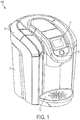
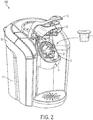
- FIGs. 1 and 2 show a perspective view of a beverage forming apparatus 100 in an illustrative embodiment that incorporates aspects of the invention.
- the beverage forming apparatus 100 may be used to form any suitable beverage, such as tea, coffee, other infusion-type beverages, beverages formed from a liquid or powdered concentrate, soups, juices or other beverages made from dried materials, or other, in this illustrative embodiment, the apparatus 100 is arranged to form coffee or tea beverages.
- a beverage cartridge 1 may be provided to the apparatus 100 and used to form a beverage that is deposited into a container 2.
- the cartridge 1 may be manually or automatically placed in a cartridge holder 3 of a beverage forming station 11 of the beverage forming machine 10.
- the cartridge holder 3 may be exposed to receive the cartridge 1 when the user operates a handle 5 or other actuator.
- movement of the handle 5 or other actuator may cause a cover 8 to move relative to the cartridge holder 3 (or the cover 8 and holder 3 to otherwise move relative to each other, e.g., by having the holder 3 move) to expose the holder 3 for reception of a cartridge 1.
- the actuator 5 may be operated to at least partially enclose the cartridge 1, e.g., so that the cover 8 moves to cooperate with the holder 3 to at least partially enclose the cartridge 1 so water or other precursor liquid can be introduced into the cartridge 1 to form a beverage.
- a cartridge 1 may be pierced to form inlet and outlet openings through which water or other precursor liquid enters the cartridge 1 and beverage that exits the cartridge 1, respectively.
- U.S. Patent 8,361,527 describes a cartridge and a system for introducing liquid into the cartridge that may be used in embodiments of this invention, and is hereby incorporated by reference in its entirety.
- aspects of the invention may be employed with any suitably arranged apparatus 100, including drip-type coffee brewers, carbonated beverage machines, and others arranged to form a beverage regardless of how the beverage is formed.
- a cartridge 1 may include any suitable materials to form a beverage, such as a carbon dioxide source used to carbonate water, a beverage mix, etc.
- the beverage forming machine 10 includes a housing 17 that houses and/or supports components of the machine 10, such as a user interface 14 used to control system operation, and defines a container receiving area 12 at which the container 2 is positionable to receive beverage dispensed by the machine 10 via a beverage outlet.
- the container 2 is associated with the machine 10 to receive a dispensed beverage and may be supported by the housing 17.
- the container 2 may be received at the container receiving area 12 so that the container 2 is at least partially surrounded by the housing 17, or the container 2 may be more exposed when at the container receiving area 12, as shown in FIG. 2 .
- a cartridge holder having an opening arranged to receive and support a cartridge may be arranged to receive cartridges of different sizes and/or shapes.
- the cartridges may have different sizes and/or shapes in a region where the cartridge holder engages with the cartridge to support the weight of the cartridge.
- the cartridge holder may engage cartridges at a rim (e.g., at or below a flange to which a lid of the cartridge is attached), and different cartridges may have different rim sizes and/or shapes.
- the cartridge holder may include an engagement portion that engages with the cartridges to support the cartridges in the holder.
- the engagement portion may include one or more movable portions that may move relative to each other to adjust a size and/or shape of an opening of the cartridge holder at which the cartridges are received.
- the movable portions may be radially movable relative to each other so as to enlarge and/or reduce the size of the opening, or to adjust a shape of the opening.
- radial movement of the movable portions may move one or more of the movable portions in a plane that is parallel to a plane of the opening. Radial movement need not necessarily involve linear movement of a portion along a radius or diameter of a circularly shaped opening.
- the opening may have any suitable shape, such as a square or other polygon, and the movable portions may move in any suitable way to change the size and/or shape of the opening, such as along a linear path, a curved path, a rotational path, etc.
- a cylindrical element may rotate about a longitudinal axis that is offset from the longitudinal center of the cylinder so as to effectively move the contact area of the cylinder radially relative to the opening.
- the moveable portions of the engagement portion may be compliant, e.g., include resilient sections that flex or otherwise resiliently deform to adjust the size of the opening so as to accommodate cartridges of different size/shape at the region where the engagement portion engages with the cartridges.
- the parts of the engagement portion at the opening may engage with a cartridge to support the weight of the cartridge or otherwise exert a force on the cartridge, e.g., to clamp the cartridge in place.
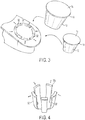
- FIG. 3 shows a partial, close up view of a cartridge holder 3 that may be employed in the FIGs. 1 and 2 embodiment.
- an opening 31 of the cartridge holder 3 is oriented in an upwardly inclined position with the opening 31 facing toward a front of the machine 10.
- an axis that is perpendicular to the plane of the opening 31 may be arranged at an angle above the horizontal of about 25 to 85 degrees, e.g., about 45 degrees.
- the handle 5 may be returned to the position of FIG.
- the cover 8 may move to a closed position, e.g., such that the cover 8 is positioned over the opening 31. Closing of the cover 8 may also cause one or more piercing elements to pierce the cartridge, e.g., to introduce liquid into the cartridge or allow beverage to exit.
- the cartridge holder 3 need not be positioned in an upwardly inclined orientation, and instead may be arranged in a horizontal, vertical, inverted or other orientation. Also, the cartridge holder 3 may move relative to the cover 8 and/or housing 17, e.g., in a horizontal, translational movement, in a pivoting motion, etc. to open and close the beverage forming station 11.
- the cartridge holder 3 may include one or more moveable portions 32 that are movable to adjust a size of the opening 31 at which the cartridges are received and engaged by the cartridge holder 3.
- the cartridge holder 3 is arranged to receive both a first cartridge 1a and a second cartridge 1b that are different from each other, e.g., the first cartridge 1a has a circular rim 19 with a diameter that is larger than the diameter of the circular rim 19 of the second cartridge 1b.
- the sizes of the rim diameters and the difference between the two may be any suitable value, e.g., one rim 19 may have diameter of about 50mm and the other rim 19 diameter may be about 63mm.
- the rim 19 diameter is relevant in this embodiment because the cartridge holder 3 engages with the cartridges 1 in a region at or near (e.g., just below) the rim 19.
- the cartridge may be received into the opening 31 such that an underside of the rim 19 rests on the movable portions 32.
- the cartridges 1 may be different in size and/or shape in these regions.
- the movable portions 32 are movable in a radial direction as shown by the arrows so that the size of the opening 31 can be adjusted to receive the differently sized cartridges 1a, 1b.
- the movable portions 32 may move in any suitable way, such as being spring biased to move radially inwardly so that when the first and/or second cartridge 1a, 1b is placed in the holder 3, the movable portions 32 are pushed outwardly by the cartridge 1a, 1b sidewall 12 until the rim 19 contacts the movable portions 32 or other stop.
- each of the movable portions 32 may be slidable in a corresponding slot of the cartridge holder 3, and a coil spring (not shown) may bias each of the movable portions 32 to move radially inwardly in the corresponding slot.
- a stop or other feature may limit each movable portion's 32 radial movement, e.g., the movable portions 32 may be normally biased to a position in which the movable portions 32 define a size and/or shape of the opening 31 that corresponds to the smaller second cartridge 1b.
- the movable portions 32 need not move to allow the holder to receive the second cartridge 1b.
- the movable portions 32 may move radially to accept the larger first cartridge 1a.
- the movable portions 32 may move in other ways, such as by a cam mechanism, screw drive, linkage, or other.
- the movable portions may each have a cam follower pin that engages with a corresponding cam slot of a cam ring that extends around the opening 31.
- the cam slots may move the follower pins radially in/out, and thereby moving the movable portions in/out.
- Other arrangements are possible, such as a diaphragm or iris mechanism used to open/close a photographic camera diaphragm so as to control an amount of light entering the camera lens or a collet chuck arrangement used to hold drill bits in a hand-held drill.
- the cartridge holder 3 may include a user-operable element, such as a knob or ring, that is movable to adjust a size and/or shape of the opening 31.
- an engagement portion of the cartridge holder may include one or more "finger” or wall portions that are arranged to move to accommodate differently sized/shaped cartridges.
- FIG. 4 shows one embodiment of an engagement portion that includes five “fingers” or wall portions 32.
- the wall portions 32 are arranged together to form a sort of basket in which the cartridges 1 are placed.
- the structure shown in FIG. 4 may be positioned in the cartridge holder 3 such that top parts 32a of the wall portions 32 define the opening 31 of the holder 3, e.g., the top parts 32a may contact an underside of the rim 19 of the cartridges 1.
- the wall portions 32 may be joined together at a bottom of the engagement portion and include at least one resilient portion that allows the wall portions 32 to flex outwardly and/or inwardly so as to adjust a size and/or shape of the opening 31.
- the smaller second cartridge 1b may be received into the opening 31 defined by the wall portions 32 with little or no movement of the wall portions 32.
- the sidewall 12 of the cartridge 1a may force the wall portions 32 to flex outwardly until the underside of the rim 19 contacts the top parts 32a of the wall portions 32.
- FIGs. 3 and 4 also illustrate another aspect of the invention, i.e., that the cartridge holder may include one or more compliant portions that are resiliently deformable or otherwise movable to accommodate differently sized and/or shaped cartridges (at least in the region where the cartridges are engaged by the cartridge holder). That is, the engagement portion of FIG. 4 is compliant in that the wall portions 32 can resiliently change shape to accommodate differently sized and shaped cartridges (the same is true of the spring-loaded movable portions 32 in FIG. 3 ). This can allow for simplified cartridge insertion into a holder 3, e.g., because neither the machine nor user need take any specific action to adjust the size and/or shape of the opening 31.
- the interaction of the cartridge 1 with the cartridge holder 3 may itself adjust the size and/or shape of the opening 31 due to the compliant nature of the engagement portion.
- compliant movable portions 32 are possible, such as forming the movable portions in FIG. 3 of a foam or silicone material that deforms to adjust a size and/or shape of the opening 31.
- a first outlet port may be used to receive beverage from a first cartridge
- a second outlet port may be used to receive beverage from a second cartridge.
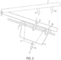
- FIG. 5 shows a schematic side view of an inlet and outlet port configuration that may be employed in an embodiment like that shown in FIG. 3 where a cartridge holder is arranged to receive cartridges of different sizes and/or shapes.
- the cover 8 of the beverage machine 10 may include an inlet port 50 and an outlet port 52a, and may be pivotal about a cover pivot 81 between an open position (shown in dashed line) and a closed position (shown in solid line).
- the inlet and outlet ports 50, 52a include piercing elements to pierce the cartridge 1 and form an opening, but piercing elements for either or both ports is not required.
- the cartridge 1 may have preformed inlet/outlet openings, or the openings may be formed by pressure applied to the outside or inside of the cartridge. For example, water pressure may be applied to the exterior of the cartridge 1 to form an inlet opening, and beverage pressure inside the cartridge may form an outlet opening in the cartridge, e.g., a septum, burstable seal or other structure may open in response to pressure.
- the inlet and outlet ports 50, 52a may form openings in a top of the cartridge 1a so that water or other fluid may be provided into the cartridge 1a via the inlet port 50, and beverage may be received from the cartridge 1a via the outlet port 52a.
- a second outlet port 52b does not contact the first cartridge 1a because the first cartridge 1a is not tall enough to contact the outlet second port 52b.
- the inlet port 50 may form an opening in a top of the cartridge 1b when the cover 8 is in the closed position, but the first outlet port 52a does not penetrate the second cartridge 1b because the second cartridge 1b is smaller in diameter at the rim 19.
- the second outlet port 52b may form an outlet opening in a bottom of the cartridge 1b because in this embodiment, the second cartridge 1b is taller than the first cartridge 1a so that the piercing element of the outlet port 52b penetrates the second cartridge 1b.
- beverage formed in the cartridge 1b may flow to the second outlet port 52b.
- inlet/outlet port arrangements are possible for use with different cartridges and are not limited to this illustrative embodiment.
- the inlet and/or outlet ports may introduce or receive fluid in any suitable locations relative to the cartridges, such as at the top, bottom, side or other locations of the cartridge, and may depend on the cartridge arrangements.
- Cartridges used with various cartridge holder embodiments may be arranged in different ways, and may depend at least in part on the nature of how a beverage medium in the cartridge is accessed to form a beverage.
- FIG. 6 shows an exploded view
- FIG. 7 shows an assembled view of one cartridge embodiment that may be used in some embodiments. Details regarding such a cartridge are provided in U.S. Patent 8,361,527 , which is hereby incorporated by reference.
- the cartridge 1 may contain any suitable beverage medium 20, e.g., ground coffee, tea leaves, dry herbal tea, powdered beverage concentrate, dried fruit extract or powder, powdered or liquid concentrated bouillon or other soup, powdered or liquid medicinal materials (such as powdered vitamins, drugs or other pharmaceuticals, nutriceuticals, etc.), and/or other beverage-making material (such as powdered milk or other creamers, sweeteners, thickeners, flavorings, and so on).
- suitable beverage medium 20 e.g., ground coffee, tea leaves, dry herbal tea, powdered beverage concentrate, dried fruit extract or powder, powdered or liquid concentrated bouillon or other soup
- powdered or liquid medicinal materials such as powdered vitamins, drugs or other pharmaceuticals, nutriceuticals, etc.
- other beverage-making material such as powdered milk or other creamers, sweeteners, thickeners, flavorings, and so on.
- the cartridge 1 includes a container 12 that includes an interior space 14 having a first chamber 14a and a second chamber 14b that are separated by a filter 30.
- the container 12 may have a frustoconical cup shape with a sidewall 17 and an opening 13, although other arrangements are possible, e.g., the container 12 may have a fluted, conical, or cylindrical shape, may be in the form of a square or rectangular cup, a domed cup, a sphere or partial sphere, or other suitable form, may have a fluted, corrugated, or otherwise shaped sidewall, and so on.
- the container 12 need not necessarily have a defined shape, as is the case with some beverage sachets and pods.
- the container 12 in this embodiment has a relatively rigid and/or resilient construction so that the container 12 tends to maintain its shape
- the container 12 could be made to have a more compliant and/or deformable arrangement, e.g., like a sachet container made from a sheet of deformable material.
- an interior space defined by the container 12 may be formed only after the container material is formed around a beverage medium, filter and/or other cartridge components, similar to when two filter paper layers (container material) are joined together around a charge of coffee grounds to form a pod or other form of cartridge.
- the opening 13 may be closed by a lid 38, e.g., a flexible sheet of foil and polymer laminate material that is attached to a rim 19 of the container 12.
- a lid 38 e.g., a flexible sheet of foil and polymer laminate material that is attached to a rim 19 of the container 12.
- the rim 19 is arranged as an annular flange-like element, the rim 19 may be arranged in other ways.
- the rim 19 may be the top edge of the sidewall 17 without any flange element.
- the filter 30 may be attached to the lid 38 at a periphery 32 that is spaced inwardly and away from the rim 19, e.g., for reasons discussed more below.
- the filter 30 may extend from the periphery 32 at least partially into the interior space 14.
- the filter 30 may have a substantially frustoconical shape with fluted or pleated sidewalls and a generally flat bottom 31, as shown.
- the filter 30 may have any suitable shape, such as a cylindrical shape, a square cup shape, a domed shape, a flat sheet, or other.
- the use of a filter 30 is not necessary, and instead the cartridge 1 may be filterless.
- the lid 38 and/or the container 12 may be pierced to introduce liquid into the cartridge and receive beverage from the cartridge.
- beverage refers to a liquid substance intended for drinking that is formed when a liquid interacts with a beverage medium.
- beverage refers to a liquid that is ready for consumption, e.g., is dispensed into a cup and ready for drinking, as well as a liquid that will undergo other processes or treatments, such as filtering or the addition of flavorings, creamer, sweeteners, another beverage, etc., before being consumed.
- To introduce liquid into the cartridge for example, as shown in FIG.
- a portion of the lid 38 generally circumscribed by the periphery 32 may be pierced by an inlet piercing element 50 (e.g., a needle) so that water or other liquid may be injected into the cartridge 1.
- an inlet piercing element 50 e.g., a needle
- Other inlet piercing arrangements are possible, such as multiple needles, a shower head, a non-hollow needle, a cone, a pyramid, a knife, a blade, etc.
- a beverage machine that uses the cartridge may include multiple piercing elements of the same type or of different types, as the invention is not limited in this respect.
- a beverage machine may include a piercing element (such as a spike) that forms an opening and thereafter a second inlet element (such as a tube) may pass through the formed hole to introduce liquid into (or conduct liquid out of) the container.
- the lid 38 may be pierced, or otherwise effectively opened for flow, by introducing pressure at an exterior of the lid 38.
- a water inlet may be pressed and sealed to the lid 38 exterior and water pressure introduced at the site. The water pressure may cause the lid 38 to be pierced or otherwise opened to allow flow into the cartridge 1.
- the lid 38 may include a valve, conduit or other structure that opens when exposed to a suitable pressure and/or when mated with a water inlet tube or other structure. Fluid introduced into the cartridge 1 may be slowed, distributed or otherwise acted on by a flow distributor 33, e.g., an element with holes to help more evenly wet the beverage medium 20.
- the cartridge 1 may also be penetrated by an outlet piercing element 52b (e.g., a needle) at a bottom 16 of the container 12, or by an outlet piercing element 52a at a second portion of the lid 38 outside of the periphery 32 and apart from the inlet opening.
- the outlet piercing arrangement may be varied in any suitable way.
- the outlet piercing element 52 may include one or more hollow or solid needles, knives, blades, tubes, and so on.
- the cartridge 1 may include a valve, septum or other element that opens to permit beverage to exit when liquid is introduced into the cartridge, but otherwise remains closed (e.g., to protect the beverage medium from external conditions such as oxygen, moisture or others).
- no piercing element for forming the outlet opening is necessarily required although may be used, e.g., to allow the valve or other element to open.
- the piercing element 52 remains in place to receive beverage as it exits the opening formed in the container 12 or lid 38.
- the piercing element 52 may withdraw after forming an opening, allowing beverage to exit the opening and be received without the piercing element 52 being extended into the cartridge 1.
- FIGs. 6-8 may be used in an embodiment like that in FIGs. 3 and 5
- other cartridge types are possible, such as those described in U.S. Patents 6607762 ; 6645537 ; 6589577 and others.
- cartridges that can be received by a cartridge holder 3 may differ in shape, in addition to, or instead of, size (at least in a region where the cartridges are engaged by the cartridge holder to support the cartridge).
- U.S. Patent 8,361,527 also describes a cartridge with an irregular rim shape, which is shown in FIG. 9 .
- the cartridge 1 is arranged similarly to that in FIGs.
- the container 12 has a rim 19 with a circular portion 19a and a spout portion 19b that extends from the circular portion 19a.
- the rim 19 has an irregular shape, and the cartridge holder 3 may be arranged to not only accommodate a larger overall rim size of the cartridge 1, but also the irregular shape of the rim 19.
- FIG. 5 is only one that illustrates how different inlet and/or outlet ports 50, 52 may be used for different cartridges.
- one or more ports 52 may be movable to exchange fluid, or not, with a cartridge in the holder 3.
- FIG. 10 shows a schematic side view of the cartridge holder 3 of FIG. 3 with a second cartridge 1b having a relatively smaller, circularly-shaped rim diameter (e.g., as seen in FIGs. 6 and 7 ) received in the holder 3.
- FIG. 11 shows a schematic side view of the cartridge holder 3 of FIG. 3 with a first cartridge 1a having a relatively larger rim diameter and an irregular rim shape (e.g., as seen in FIG.
- FIG. 10 The view in FIG. 10 is similar to that shown in FIG. 5 for the second cartridge 1b. That is, the second cartridge 1b, which has a relatively small circular rim 19 in this embodiment, is pierced at the top by the inlet port 50 to accommodate downward inflow of fluid into the cartridge 1b, and pierced at the bottom by the second outlet port 52b to accommodate downward outflow of beverage from the cartridge 1b.
- the top of the cartridge is pierced by both the inlet port 50 and the first outlet port 52a.
- the first cartridge 1a may be pierced by the first outlet port 52a at an area of the lid 38 which is located in the spout area near the spout portion 19b of the rim 19, although other areas of the lid are possible.
- Inclining the cartridge holder 3 and cartridge 1a such that the spout portion 19b is at a lower end of the cartridge 1a may aid in removing beverage from the cartridge 1a, since beverage may collect in the spout area for outflow in an upward direction.
- the first cartridge 1a is too short to contact the second outlet port 52b, this need not be the case and the first cartridge 1a may be made taller.
- the second outlet port 52b may be moved out of a cartridge receiving space so that the port 52b can avoid contact with the cartridge 1a.
- Such movement may be accomplished in different ways, such as by a motorized drive, a linkage, having a user physically move one of the ports into/out of a cartridge receiving area, and others.
- one or more ports may be selected for use with a cartridge based on one or more features of the cartridge that is inserted into the cartridge holder 3.
- insertion of a cartridge having a relatively larger rim diameter may cause the second outlet port 52b to be moved out of a cartridge receiving area so as to avoid potential contact with the cartridge 1.
- insertion of a particular cartridge type may release a port for movement, e.g., insertion of the larger rim cartridge may release the second outlet port 52b so that the cartridge 1a may contact the second outlet port 52b and move it.
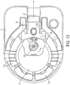
- FIGs. 12 and 13 show an illustrative embodiment in which insertion of a cartridge having a spout, such as that shown in FIG. 9 , causes the second outlet port 52b to move out of a cartridge receiving area.
- one of the movable portions 32 e.g., a trigger 33
- the trigger 33 may be coupled to the second outlet port 52b by a linkage that causes the second outlet port 52b to pivot about an axis 53 as the sliding portion 32 is moved radially outwardly.
- the trigger 33 may be spring loaded such that when the first cartridge 1a having a spout is removed from the cartridge holder 3, the trigger 33 may move radially inwardly, allowing the second outlet port 52b to pivot back into a cartridge receiving area. Thus, if a second cartridge 1b is inserted into the holder 3 having no spout, the trigger 33 may remain stationary, and the second outlet port 52b may pierce the second cartridge 1b at its bottom or other suitable location.
- the second outlet port 52b may include or be connected to a conduit to conduct beverage from the second cartridge 1b to a dispensing area of the beverage forming machine 10, or beverage may simply exit the cartridge 1b without being conducted by a conduit.
- movement of the trigger or other part of the cartridge holder 3 may release one or more ports for movement, e.g., based on contact with a cartridge, so that the port does not pierce or otherwise interact with the cartridge to exchange fluid.
- FIG. 14 shows an embodiment in which a trigger 33 like that in FIGs. 12 and 13 may be moved by a contact with a spout of a first cartridge 1a. Movement of the trigger 33 may release the second outlet port 52b for movement upon contact with the cartridge 1a so that the second outlet port 52b does not substantially resist movement.
- a bottom of the first cartridge 1a may contact the second outlet port 52b and pivot the port 52b about a horizontal axis 54 so the port 52b moves out of a cartridge receiving area and does not pierce the cartridge 1a.
- the trigger 33 is linked to a latch 331 that engages with the second outlet port 52b to prevent pivoting of the port 52b about the axis 54 when the trigger 33 is positioned to the left.
- the trigger 33 may be spring loaded to move to the left as shown in FIG. 14 ; thus, the latch 331 may normally engage the port 52b unless the trigger 33 is moved, e.g., by a first cartridge 1a.
- inlet and/or outlet ports may be effected by a motor drive or other mechanism, and may be controlled by based on reading of a machine readable feature or other indicia on a cartridge.
- the machine 10 may read an RFID tag, barcode, etc., on a cartridge 1, and make suitable port selections based on a cartridge type or other information associated with the identified cartridge 1.
- FIGs. 15 and 16 show an exploded view and an assembled view of a cartridge holder, associated cover, handle actuator and other selected components of a beverage forming apparatus 10.
- the engagement portion of the cartridge holder 3 includes a plurality of movable portions 32 in the form of "fingers" or wall portions that are joined together at a bottom of the engagement portion, as in FIG. 4 .
- This embodiment also includes a trigger 33 to cause and/or allow movement of an outlet port from a cartridge receiving area. That is, this embodiment is arranged to receive both a first cartridge 1a that has an irregular rim having a circular portion and spout portion, and a second cartridge 1b that has a circular rim with a diameter smaller than that of the circular portion of the first cartridge 1a.
- the wall portions 32 of the engagement portion are arranged to provide a suitable opening for the second outlet port 52b to move into/out of the cartridge receiving area as needed.
- the engagement portion is received into a hole 35 in a portion of the frame 6 that helps define the cartridge holder 3.
- the engagement portion is supported in the hole 35 so that the wall portions 32 located opposite the trigger 33 have a smaller range of radial motion than wall portions 32 located nearer the trigger 33. That is, one or more wall portions 32 opposite the trigger 33 may be permitted to move radially outwardly to some extent, but then contact the hole 35 or other part of the frame 6 so the wall portion(s) 32 are prevented from further outward radial movement. This may help the cartridge holder 3 to urge a cartridge 1a having a spout section into proper contact with the trigger 33 and move the trigger 33 suitably radially outwardly.
- the trigger 33 may be biased to move radially inwardly by a spring or other resilient element of suitable strength so that insertion of the cartridge having a spout section causes the wall portion(s) 32 opposite the trigger 33 to flex outwardly and contact the hole 35 or other stop of radial movement before the cartridge 1a is fully inserted into the opening 31. Further insertion of the cartridge 1a may then cause the trigger 33 to slide outwardly because the wall portion(s) 32 opposite the trigger 33 are prevented from further outward radial movement. This may ensure that the cartridge 1 is properly positioned for piercing by an inlet and/or outlet piercing element.
- FIG. 16 also shows how in this embodiment the cover 8 may be moved relative to the cartridge holder 3.
- the cover 8 is arranged for pivotal movement relative to the frame 6 about a cover pivot 61 based on movement of a handle 5 which is pivotally mounted to the cover 8 at a handle pivot 63.
- a plate 81 is also pivotally mounted to the frame 6 about a plate pivot 62 and moves based on movement of the handle 5. The plate 81 operates to contact a cartridge 1 placed in the cartridge holder 3, and push the cartridge 1 into the holder 3 so that the cartridge 1 is fully received into the holder 3 before the cover 8 engages the cartridge 1. This helps ensure that the cartridge 1 is fully seated in the holder 3 before piercing elements on the cover 8 pierce the cartridge 1.
- a pivot pin 64 of the handle 5 is engaged with a slot 82 of the plate 81 and moves in a cam slot 65 of the frame 6 so that as the handle 5 is pivoted about the handle pivot 63 from an open position (shown in FIG. 16 ) to a closed position, the pivot pin 64 moves in the cam slot 65, thereby pivoting the plate 81 about the plate pivot 62 toward the cartridge holder 3.
- the cover 8 is pivoted about the cover pivot 63 to move toward the cartridge holder 3.
- the plate 81 is arranged to contact a cartridge 1 in the holder 3 before the cover 8, forcing the cartridge 1 to be seated into the holder 3. This action may cause movable portions 32 of the engagement portion to move as needed to receive the cartridge 1.
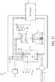
- FIG. 17 shows a schematic block diagram of various components that may be included in a beverage forming apparatus 100 in one illustrative embodiment.
- a beverage forming apparatus 100 may be configured in a variety of different ways, and thus aspects of the invention should not be narrowly interpreted as relating only to one type of beverage forming apparatus.
- water or other precursor liquid may be provided by a liquid supply 15 to mix with a beverage material at a beverage forming station 11.
- the beverage material (such as coffee grounds, tea leaves, a powdered drink mix, etc.) may be provided in a cartridge 1, or not, and beverage produced by mixing the liquid with the beverage material may be dispensed into the container 2 via a beverage outlet.
- the liquid supply 15 in this embodiment controls the volume of liquid provided to the beverage forming station 11 by filling the tank to a liquid dispense level 159, 160 and then pressurizing the tank 152 by way of an air pump 154 so that liquid in the tank 152 is forced out of the conduit 156 to the beverage forming station 11.
- the volume of liquid delivered to the beverage forming station 11 is equal to the volume in the tank 152 between the liquid delivery level 159, 160 and a post-delivery level 158 at a bottom of the conduit 156 in the tank 152. Since there are two delivery levels 159, 160 in this embodiment, two different volumes can be provided to the beverage forming station 11. However, more than two levels, or a single level, may be used.
- the liquid supply 15 provides liquid to the tank 152 via a valve 151 that is coupled to a source W.
- the source W may have any suitable arrangement, e.g., may provide liquid from a storage tank, a mains water supply or other source.
- the liquid provided to the tank 152 may vary in temperature by a wide degree depending on various factors, such as time of year, a temperature of a room in which the machine 10 is located, etc.
- the temperature of liquid in the reservoir may vary between room temperature (e.g., if liquid sits in the reservoir for an extended time) and a cooler temperature (e.g., if the reservoir has just been filled with water that is dispensed from a tap).
- the valve 151 is controlled by the control circuit 16 to open and close to provide a desired volume of liquid to the tank 152. For example, if the tank 152 is empty or at the post-dispense level 158, the valve 151 may be opened until a conductive probe or other liquid level sensor 157 provides a signal to the control circuit 16 that indicates when liquid arrives at the dispense level 159, 160. In response to the level sensor 157 detecting liquid at the sensor 157, the control circuit 16 may close the valve 151.
- the control circuit 16 may close the valve 151.
- other arrangements are possible, such using a pump to move liquid from a storage reservoir to the tank 152.
- the liquid level sensor includes a pair of conductive probes capable of contacting liquid in the tank 152 and providing a signal (e.g., a resistance change) indicative of liquid being present at respective dispense levels 159 or 160 in the tank 152
- the liquid level sensor may be arranged in other ways.
- the sensor may include a microswitch with an attached float that rises with liquid level in the tank 152 to activate the switch.
- the liquid level sensor may detect a capacitance change associated with one or more liquid levels in the tank, may use an optical emitter/sensor arrangement (such as an LED and photodiode) to detect a change in liquid level, may use a pressure sensor, may use a floating magnet and Hall effect sensor to detect a level change, and others.
- the liquid level sensor is not necessarily limited to a conductive probe configuration.
- the liquid level sensor may include two or more different types sensors to detect different levels in the tank.
- a pressure sensor may be used to detect liquid at the dispense level 160 (e.g., complete filling of the tank 152 may coincide with a sharp rise in pressure in the tank 152), while a conductive probe may be used to detect liquid at the other dispense level 159.
- a liquid level sensor need not be used to fill the tank to the dispense level 159, 160.
- other techniques may be used to suitably fill the tank 152, such as opening the valve 151 for a defined period of time that is found to correspond to approximate filling of the tank 152 to the desired level.
- a pump e.g., a centrifugal pump, piston pump, solenoid pump, diaphragm pump, etc.
- gravity feed e.g., gravity feed, or other, and the way by which the tank is filled to the dispense level 159, 160 may depend on the technique used to provide liquid to the tank.
- control of a volume of liquid provided to fill the tank 152 to the dispense level 159, 160 may be performed by running a pump for a predetermined time, detecting a flow rate or volume of liquid entering the tank 152 (e.g., using a flow meter), operating a pump for a desired number of cycles (such as where the pump is arranged to deliver a known volume of liquid for each cycle), detecting a pressure rise in the tank 152 using a pressure sensor, or using any other viable technique.
- Liquid in the tank 152 may be heated by way of a heating element 153 whose operation is controlled by the control circuit 16 using input from a temperature sensor or other suitable input.
- heating of the liquid is not necessary, and instead (or additionally) the apparatus 100 may include a chiller to cool the liquid, a carbonator to carbonate the liquid, or otherwise condition the liquid in a way that alters the volume of liquid in the tank 152.
- a chiller to cool the liquid
- a carbonator to carbonate the liquid
- the liquid conditioner components of the liquid supply 15 that heat, cool, carbonate or otherwise condition liquid supplied to the beverage forming station 11 are referred to as a "liquid conditioner."
- liquid may be discharged from the tank 152 by an air pump 154 operating to force air into the tank 152 to pressurize the tank and force liquid to flow in the conduit 156 to the beverage forming station 11. Since the conduit extends downwardly into the tank 152, the volume of liquid delivered to the forming station 11 is defined as the volume in the tank 152 between the dispense level 159, 160 and the bottom end of the conduit 156. Again, liquid may be caused to flow from the tank 152 to the beverage forming station 11 in other ways. For example, a pump may be used to pump liquid from the tank 152 to the forming station 11, liquid may be allowed to flow by gravity from the tank 152, and others.
- a vent 155 which can be opened or closed to vent the tank 152, may be provided to allow the tank 152 to be filled without causing a substantial rise in pressure in the tank 152 and to allow liquid to be delivered from the tank 152 by pressurizing the tank using the air pump 154.
- the vent 155 is actually not controlled by the control circuit 16, but remains always open with an orifice of suitable size to allow venting for filling of the tank 152, and air pressure buildup in the tank 152 to allow liquid delivery.
- Other flow control features may be provided as well, such as a check valve or other flow controller that can prevent backflow in the conduit between the source W and the tank 152, or between the tank 152 and the beverage forming station 11.
- the beverage forming station 11 may use any beverage making ingredient, such as ground coffee, tea, a flavored drink mix, or other beverage medium, e.g., contained in a cartridge 1 or not. Alternately, the beverage forming station 11 may function simply as an outlet for heated, cooled or otherwise conditioned water or other liquid, e.g., where a beverage medium is contained in the container 2. Once liquid delivery from the tank 156 to the station 11 is complete, the air pump 154 (or other air pump) may be operated to force air into the conduit 156 to purge liquid from the beverage forming station 11, at least to some extent.
- any beverage making ingredient such as ground coffee, tea, a flavored drink mix, or other beverage medium, e.g., contained in a cartridge 1 or not.
- the beverage forming station 11 may function simply as an outlet for heated, cooled or otherwise conditioned water or other liquid, e.g., where a beverage medium is contained in the container 2.
- control circuit 16 Operation of the valve 151, air pump 154 and other components of the apparatus 100 may be controlled by the control circuit 16, e.g., which may include a programmed processor and/or other data processing device along with suitable software or other operating instructions, one or more memories (including non-transient storage media that may store software and/or other operating instructions), temperature and liquid level sensors, pressure sensors, input/output interfaces, communication buses or other links, a display, switches, relays, triacs, or other components necessary to perform desired input/output or other functions.
- the control circuit 16 e.g., which may include a programmed processor and/or other data processing device along with suitable software or other operating instructions, one or more memories (including non-transient storage media that may store software and/or other operating instructions), temperature and liquid level sensors, pressure sensors, input/output interfaces, communication buses or other links, a display, switches, relays, triacs, or other components necessary to perform desired input/output or other functions.
- the beverage forming apparatus may include multiple detectors to detect characteristics of a cartridge received in the cartridge holder. Operation of the apparatus 100 may be controlled by the control circuit 16 based on information detected by the detectors.
- the apparatus includes first, second and third detectors 161, 162, 163 that each detect a different characteristic regarding a cartridge 1 in the cartridge holder 3.
- a first detector 161 may detect the presence or absence of a cartridge 1, e.g., may include an infrared detector that illuminates an area of the cartridge holder 3 with infrared light and detects whether infrared light is reflected by a cartridge or not.
- Detection of a suitable amount or other level of reflected light may be used to determine that a cartridge 1 is present, whereas no or lower light levels may indicate the absence of a cartridge.
- Such an infrared detector may include an infrared emitter and a photodetector or other suitable element(s).
- Other detector arrangements are possible, such as mechanical switches, a bar code reader, an RFID interrogator, etc.
- a second detector 162 may detect a type of cartridge, e.g., may detect whether a cartridge includes a spout portion or not.
- the second detector may be arranged in a variety of different ways, and in one embodiment may include the trigger 33 of FIGs. 12-16 and a switch to detect movement of the trigger 33.
- the trigger 33 may include a magnet that moves with the trigger 33 and a reed or other suitable switch may detect the presence or absence of the magnet, thereby detecting movement of the trigger 33.
- Other arrangements for the second detector 162 are possible, such as an optical detector, bar code reader, etc.
- the third detector 163 may detect information related to whether a cartridge is authorized for use with the beverage forming apparatus, and may include a bar code reader, a camera or other image capture device with image analysis capability, an RFID interrogator, and others.
- the third detector 163 includes an illumination element that illuminates a portion of a cartridge with suitable light, e.g., one or more LED sources may illuminate a cartridge with light having any suitable set of wavelengths.
- the third detector 163 may also include a light detector that is arranged to detect light emitted and/or reflected by a cartridge portion and assess whether the light detected is consistent with an authorized cartridge.
- authorized cartridges may carry a security ink or other material that provides a specific spectral response to being illuminated by certain light. The third detector 163 may detect whether the spectral response is present, and if so, indicate that the cartridge is authorized for use in forming a beverage.
- the control circuit 16 may control operation of the liquid supply 15 and/or other portions of the apparatus 100 based on information detected by the first, second and/or third detectors 161, 162, 163. For example, if no cartridge is detected by the first detector 161 and an operator presses a brew indication button, the control circuit 16 may cause the apparatus 100 to perform a cleaning operation by which the cartridge holder 3 and/or other parts of the apparatus 100 are cleaned. However, if a cartridge 1 is detected, the control circuit 16 may cause the display of beverage forming options to a user at the user interface 14, may start a beverage creation cycle, may begin heating of water in the tank 152, etc.
- the control circuit 162 may control the system to adjust beverage forming parameters in some way, e.g., by adjusting a heating temperature, an amount of liquid used to make a beverage, displaying and requiring particular user input to form a beverage, and so on.
- the control circuit 16 may prevent all or certain ones of beverage production processes if a cartridge is not detected by the third detector 163 to be an authorized one. Instead, the control circuit 16 may only permit a cleaning operation, provided no cartridge is detected in the cartridge holder. Alternately, the control circuit 16 may cause the apparatus to perform a default beverage process, e.g., including a specific set of brew water temperature, volume, delivery time, etc.
- the cartridge 1 may take any suitable form such as those commonly known as a sachet, pod, capsule, container or other.
- the cartridge 1 may include an impermeable outer covering within which is housed a beverage medium, such as roasted and ground coffee or other.
- the cartridge 1 may also include a filter so that a beverage formed by interaction of the liquid with the beverage medium passes through the filter before being dispensed into a container 2.
- cartridges in the form of a pod may use the outer portion of the cartridge 1 to filter the beverage formed.
- the cartridge 1 in this example may be used in a beverage machine to form any suitable beverage such as tea, coffee, other infusion-type beverages, beverages formed from a liquid or powdered concentrate, etc.
- the cartridge 1 may contain any suitable beverage medium, e.g., ground coffee, tea leaves, dry herbal tea, powdered beverage concentrate, dried fruit extract or powder, powdered or liquid concentrated bouillon or other soup, powdered or liquid medicinal materials (such as powdered vitamins, drugs or other pharmaceuticals, nutriaceuticals, etc.), and/or other beverage-making material (such as powdered milk or other creamers, sweeteners, thickeners, flavorings, and so on).
- the cartridge 1 contains a beverage medium that is configured for use with a machine that forms coffee and/or tea beverages, however, aspects of the invention are not limited in this respect.
- beverage refers to a liquid substance intended for drinking that is formed when a liquid interacts with a beverage medium.
- beverage refers to a liquid that is ready for consumption, e.g., is dispensed into a cup and ready for drinking, as well as a liquid that will undergo other processes or treatments, such as filtering or the addition of flavorings, creamer, sweeteners, another beverage, etc., before being consumed.
Landscapes
- Engineering & Computer Science (AREA)
- Food Science & Technology (AREA)
- Mechanical Engineering (AREA)
- Apparatus For Making Beverages (AREA)
- Devices For Dispensing Beverages (AREA)
Description
- This invention relates to beverage forming systems, such as coffee brewers that use a liquid to form a coffee beverage.
- Beverage forming systems that use a liquid, such as water, to form a beverage are well known. For example,
U.S. Patent 8,361,527 discloses a beverage forming system that uses a beverage cartridge containing a beverage material to make a beverage by introducing liquid into the cartridge. Liquid provided to the cartridge may be heated in a tank prior to delivery to the cartridge. DocumentUS 2013/0139699 A1 discloses a coffee maker (10e) comprising a spring element (36) configured to extend into the base of a coffee holder (30) within which is received a coffee pod (31d). The coffee maker (10e) includes an opposing horizontal ram (42a) configured to force the body of the coffee holder (30) against the spring element (36) such that the coffee pod (31d) contained within the coffee holder (30) is compressed (see Figs. 48A-48C). - Aspects of the invention relate to methods and apparatus for receiving cartridges of different size and/or shape in a cartridge holder of a beverage forming machine. For example, in some embodiments, the cartridge holder may be arranged to receive and support cartridges that have different sizes, e.g., circular rims of different diameters, and/or that have different shapes, e.g., one cartridge may have a circular rim while another cartridge may have a rim with an irregular shape, without the user having to manipulate an adapter or other component of the cartridge holder. In one embodiment, the cartridge holder may be arranged to expand and/or contract to adjust a size and/or shape of an opening in which cartridges are received. Thus, a user may simply place cartridges having different sizes or shapes in the cartridge holder without having to take any specific action to adjust a receiving opening of the holder or otherwise configure the machine.
- In some embodiments, the cartridge holder may have an engagement portion that engages with, and optionally supports the weight of, cartridges placed in the holder. The engagement portion may include one or more radially movable portions which can move to adjust a size and/or shape of an opening in which the cartridges are received. In some embodiments, the engagement portion may include one or more compliant portions which can move resiliently such that the act of placing a cartridge in the holder causes movement of the compliant portions and adjustment of the size and/or shape of the receiving opening. Such an arrangement may make for an easy and convenient way for users to place differently sized/shaped cartridges in a cartridge holder.
- In some embodiments, the cartridges may be differently sized and/or shaped in a region where the cartridge holder engages with, and supports the weight of, the cartridge. For example, an engagement portion of the cartridge holder may engage with cartridges at a rim of the cartridges (e.g., at a location just below and/or around a top edge where a sealing lid is attached to the cartridge). In some embodiments, the different cartridges may have rims of different diameters and/or shapes. For example, in one embodiment, a first cartridge may have a rim with an irregular shape (such as a rim with a circular section and a spout portion extending from one part of the circular section), and a second cartridge may have a circular rim. Despite these different shapes at the cartridge rim, the cartridge holder may accommodate both cartridge types while supporting the cartridges at a location at or near the rim.
- In an aspect of the invention, a beverage forming machine may provide water or other fluid to different cartridges, and/or may receive beverage from different cartridges, using different inlet and/or outlet ports. For example, a first cartridge may receive water from an inlet port that pierces a top lid of the cartridge, and beverage may exit the cartridge to an outlet port that also pierces the top lid of the cartridge (though in a different location than the inlet port). However, a second cartridge held by the same cartridge holder may receive water from an inlet port that pierces the cartridge at a different location (such as the bottom of the cartridge as opposed to the top), and/or beverage may exit the second cartridge to an outlet port that pierces the cartridge at a different location (such as the bottom of the cartridge). For example, inflow of water into a first cartridge may be downwardly into the cartridge, while beverage outflow is upwardly from the cartridge. In contrast, inflow of water into a second cartridge may be downwardly into the cartridge, but beverage outflow may be downwardly from the second cartridge. Thus, inflow and/or outflow for different cartridges may occur in different relative places and/or directions.
- In one embodiment, a first cartridge may be pierced in two locations at a top lid for inlet and outlet openings, respectively. Water or other fluid may be introduced into the cartridge in a downward direction through the inlet opening, and beverage may exit the cartridge in an upward direction through the outlet opening. In contrast, a second cartridge may be pierced in one location at the top lid for an inlet opening, and pierced at a location below the lid, e.g., at a bottom of the cartridge, for an outlet opening. Thus, water or other fluid may be introduced into the cartridge in a downward direction through the inlet opening, and beverage may exit the cartridge in a downward direction through the outlet opening. Such different flows may be accommodated by a single cartridge holder which can not only accommodate differently sized and/or shaped cartridges, but also different flow arrangements for fluid into and beverage out of the cartridges.
- In one aspect of the invention, a beverage forming apparatus includes a frame arranged to support components of the beverage forming apparatus, and a cartridge holder including a cartridge engagement portion that defines an opening and that is arranged to engage with a cartridge placed in the opening. The engagement portion may include one or more radially movable sections that are movable to accommodate and engage with first and second cartridges that are differently sized and/or shaped relative to each other in a region where the engagement portion engages with the first and second cartridges. For example, the first and second cartridges may have differently sized rims, and the engagement portion may have one or more sections move to accommodate one or both of the cartridges. A cover may cooperate with the cartridge holder to at least partially enclose a cartridge held by the cartridge holder for formation of a beverage using the cartridge. For example, the cover may move to cover a part of a cartridge, or the cover may be fixed to the frame and the cartridge holder may move so that the cover is positioned over at least part of a cartridge. A liquid supply system at least partially supported by the frame may be arranged to provide a liquid for combination with a beverage medium in a cartridge held by the cartridge holder to form a beverage.
- In one embodiment, the cartridge engagement portion may include a plurality of wall sections that are movable away from (and/or toward) each other to accommodate the first or second cartridge. The cartridge engagement portion may include at least one trigger that is mounted for sliding movement away from the opening, e.g., the trigger may be movable to receive a spout of the first or second cartridge. In some embodiments, the cartridge engagement portion may engage with a rim of the first and second cartridge to support a weight of the cartridge, where the first cartridge has a rim with a first diameter, and the second cartridge has a rim with a second diameter that is smaller than the first diameter. The rim of the second cartridge may be circular, and the rim of the first cartridge may have a circular portion and a spout portion that extends outwardly from the circular portion.
- In one embodiment, the cartridge engagement portion may include a plurality of wall portions that extend upwardly from a bottom of the engagement portion, where the wall portions are joined together, to a top of the engagement portion. The wall portions located at the top of the engagement portion may be radially movable relative to each other, e.g., so as to move to accommodate and engage with the first and second cartridge. The wall portions may be radially movable based on flexing movement of the wall portions relative to the bottom of the engagement portion or may be movable in other ways, such as by pivoting about a hinge.
- In one embodiment, the cover includes a liquid inlet to introduce liquid from the liquid supply system to a cartridge held in the cartridge holder, and/or includes a first beverage outlet to receive beverage exiting a cartridge held in the cartridge holder. The apparatus may also include a second beverage outlet mounted to the cartridge holder and arranged to receive beverage exiting a cartridge held in the cartridge holder. The first and second beverage outlets may be selectively employed to receive beverage from a cartridge, e.g., depending on a type of cartridge. For example, the second beverage outlet may be selectively movable into and out of a cartridge receiving area of the cartridge holder based on whether the first or second cartridge is received in the cartridge holder. The liquid inlet and the first and second beverage outlets may each include a piercing element to pierce a cartridge, and the piercing elements of the liquid inlet and the first beverage outlet may face downwardly and the second beverage outlet may face upwardly.
- In one embodiment, the engagement portion includes a plurality of radially movable sections and at least one of the radially movable sections has a smaller range of motion than at least one other radially movable section. This arrangement may help properly locate cartridges in the cartridge holder, e.g., so that an inlet and/or outlet may properly align with the cartridge. For example, since different cartridges may have different sizes, the engagement portions may be required to move different amounts to accommodate different cartridges. However, if the engagement portions do not move in an appropriate way, the cartridge may be misaligned with respect to an inlet and/or outlet. Thus, by having one or more engagement portions have a limited range of motion, the engagement portions may effectively function as stops for one or more cartridges, helping to ensure proper positioning of the cartridges. In one embodiment, the cartridge holder is arranged to receive a cartridge with a rim having a partially circular portion and a spout section extending outwardly from the partially circular portion. The at least one radially movable section with a smaller range of motion may be located on a side of the opening opposite where the spout section of the cartridge is received. This positioning of the movable section having a smaller range of motion can be helpful where the spout section contacts a trigger, which may resist radially outward movement to a greater extent than other engagement portions. By limiting movement of a movable portion opposite the trigger, the radially inward force of the trigger on the cartridge may be resisted, helping to properly position the cartridge.
- In another aspect of the invention, a method for forming a beverage using a beverage forming apparatus includes providing a beverage forming apparatus having a cartridge holder with an engagement portion arranged to engage with a cartridge placed in an opening of the cartridge holder. A first or second cartridge may be provided into the opening of the cartridge holder, where the first and second cartridges are differently sized and/or shaped relative to each other in a region where the engagement portion engages with the first and second cartridges to support a weight of the cartridge. One or more sections of the engagement portion may be moved radially to accommodate and engage with a region of the first or second cartridge provided into the opening, and liquid may be combined with a beverage medium in the first or second cartridge held by the cartridge holder to form a beverage. In one embodiment, a plurality of wall sections may move away from each other to accommodate the first or second cartridge.
- In one embodiment, a cover may cooperate with the cartridge holder to at least partially enclose a cartridge and liquid may be introduced from the liquid supply system to a cartridge held in the cartridge holder via a liquid inlet of the cover. Beverage may be received from the cartridge at a first beverage outlet, which may be attached to the cover. In some cases, beverage may be received at a first beverage outlet if a first cartridge is received in the cartridge holder, but beverage may be received at a second beverage outlet if a second cartridge is received in the cartridge holder. For example, the second beverage outlet may be selectively moved out of a cartridge receiving area of the cartridge holder if the first cartridge is received in the cartridge holder, and the first beverage outlet may interact with the first cartridge to receive beverage.
- In another aspect of the invention, a beverage forming apparatus includes a frame arranged to support components of the beverage forming apparatus, and a cartridge holder having a cartridge engagement portion that defines an opening and that is arranged to engage with a cartridge placed in the opening and support a weight of the cartridge. The engagement portion may include one or more compliant sections that are movable to adjust a size and/or shape of the opening to accommodate and engage with first and second cartridges that are differently sized and/or shaped relative to each other in a region where the engagement portion engages with the first and second cartridges. A cover may be arranged to cooperate with the cartridge holder to at least partially enclose a cartridge held by the cartridge holder for formation of a beverage using the cartridge, and a liquid supply system may be arranged to provide a liquid for combination with a beverage medium in a cartridge held by the cartridge holder to form a beverage. In one embodiment, the one or more compliant sections each include a resilient element that deforms in response to insertion of the first or second cartridge into the opening of the cartridge holder. For example, the one or more compliant sections may include a plurality of wall sections that are movable away from each other to accommodate the first or second cartridge. The one or more compliant sections may include at least one trigger that is mounted for sliding movement away from the opening, e.g., the trigger may be movable to receive a spout of the first or second cartridge. Other features described above may be incorporated as well, such as having the one or more compliant sections include wall elements that are joined together and are capable of flexing to receive one or more cartridges.
- In another aspect of the invention, a method for forming a beverage using a beverage forming apparatus includes providing a beverage forming apparatus having a cartridge holder with an engagement portion arranged to engage with a cartridge placed in an opening of the cartridge holder and support a weight of the cartridge. The engagement portion may include one or more resilient elements that are movable to adjust a size and/or shape of the opening. A first or second cartridge may be placed into the opening of the cartridge holder, where the first and second cartridges are differently sized and/or shaped relative to each other in a region where the engagement portion engages with the first and second cartridges to support a weight of the cartridge. One or more resilient elements of the engagement portion may be moved to adjust a size and/or shape of the opening and to accommodate and engage with a region of the first or second cartridge provided into the opening, and liquid may be combined with a beverage medium in the first or second cartridge held by the cartridge holder to form a beverage.
- These and other aspects of the invention will be apparent from the following description and claims.
- Aspects are described below with reference to the following drawings in which like numerals reference like elements, and wherein:
-
FIG. 1 is a front perspective view of a beverage forming apparatus in an illustrative embodiment; -
FIG. 2 is a front perspective view of theFIG. 1 embodiment with the cartridge holder exposed to receive a cartridge; -
FIG. 3 is a perspective side view of a cartridge holder arranged to receive cartridges having different sizes; -
FIG. 4 is a perspective side view of an engagement portion for the cartridge holder mechanism in theFIG. 3 embodiment; -
FIG. 5 is a schematic side view of a cartridge holder and cover in an illustrative embodiment; -
FIG. 6 is an exploded view of a beverage cartridge in an illustrative embodiment; -
FIG. 7 is an assembled, cross-sectional view of the cartridge ofFIG. 6 ; -
FIG. 8 is a cross-sectional view of theFIG. 6 cartridge and optional inlet and outlet locations for the cartridge; -
FIG. 9 is perspective view of another beverage cartridge arrangement that may be received by a cartridge holder also arranged to receive the cartridge ofFIGs. 6-8 ; -
FIG. 10 is schematic side view of a cartridge holder and cover in an illustrative embodiment in which different outlet ports are used for different cartridges; -
FIG. 11 is a schematic side view of the cartridge holder ofFIG. 10 illustrating how a different outlet port is used with a different cartridge than that shown inFIG. 10 ; -
FIG. 12 is a side view of a cartridge holder having an outlet port that is pivotal about a vertical axis; -
FIG. 13 is a top view of theFIG. 12 cartridge holder; -
FIG. 14 is a side view of a cartridge holder having an outlet port that is pivotal about a horizontal axis; -
FIG. 15 is a partially exploded view of a cartridge holder employing the engagement portion ofFIG. 4 ; -
FIG. 16 is a perspective view of a cartridge holder, associated cover and components for moving the cover in an illustrative embodiment; and -
FIG. 17 is a schematic diagram of components of a beverage forming apparatus in an illustrative embodiment. -
FIGs. 1 and2 show a perspective view of abeverage forming apparatus 100 in an illustrative embodiment that incorporates aspects of the invention. Although thebeverage forming apparatus 100 may be used to form any suitable beverage, such as tea, coffee, other infusion-type beverages, beverages formed from a liquid or powdered concentrate, soups, juices or other beverages made from dried materials, or other, in this illustrative embodiment, theapparatus 100 is arranged to form coffee or tea beverages. As is known in the art, abeverage cartridge 1 may be provided to theapparatus 100 and used to form a beverage that is deposited into a container 2. Thecartridge 1 may be manually or automatically placed in acartridge holder 3 of abeverage forming station 11 of the beverage forming machine 10. For example, thecartridge holder 3 may be exposed to receive thecartridge 1 when the user operates ahandle 5 or other actuator. In this embodiment, movement of thehandle 5 or other actuator may cause acover 8 to move relative to the cartridge holder 3 (or thecover 8 andholder 3 to otherwise move relative to each other, e.g., by having theholder 3 move) to expose theholder 3 for reception of acartridge 1. With thecartridge 1 placed in thecartridge holder 3, theactuator 5 may be operated to at least partially enclose thecartridge 1, e.g., so that thecover 8 moves to cooperate with theholder 3 to at least partially enclose thecartridge 1 so water or other precursor liquid can be introduced into thecartridge 1 to form a beverage. For example, with thecartridge 1 held in thebeverage forming station 11 by thecartridge holder 3, thecartridge 1 may be pierced to form inlet and outlet openings through which water or other precursor liquid enters thecartridge 1 and beverage that exits thecartridge 1, respectively.U.S. Patent 8,361,527 describes a cartridge and a system for introducing liquid into the cartridge that may be used in embodiments of this invention, and is hereby incorporated by reference in its entirety. Of course, aspects of the invention may be employed with any suitably arrangedapparatus 100, including drip-type coffee brewers, carbonated beverage machines, and others arranged to form a beverage regardless of how the beverage is formed. For example, acartridge 1 may include any suitable materials to form a beverage, such as a carbon dioxide source used to carbonate water, a beverage mix, etc. - In this embodiment, the beverage forming machine 10 includes a
housing 17 that houses and/or supports components of the machine 10, such as auser interface 14 used to control system operation, and defines acontainer receiving area 12 at which the container 2 is positionable to receive beverage dispensed by the machine 10 via a beverage outlet. Thus, at thecontainer receiving area 12, the container 2 is associated with the machine 10 to receive a dispensed beverage and may be supported by thehousing 17. The container 2 may be received at thecontainer receiving area 12 so that the container 2 is at least partially surrounded by thehousing 17, or the container 2 may be more exposed when at thecontainer receiving area 12, as shown inFIG. 2 . - In accordance with an aspect of the invention, a cartridge holder having an opening arranged to receive and support a cartridge may be arranged to receive cartridges of different sizes and/or shapes. In particular, the cartridges may have different sizes and/or shapes in a region where the cartridge holder engages with the cartridge to support the weight of the cartridge. For example, the cartridge holder may engage cartridges at a rim (e.g., at or below a flange to which a lid of the cartridge is attached), and different cartridges may have different rim sizes and/or shapes. In some embodiments, the cartridge holder may include an engagement portion that engages with the cartridges to support the cartridges in the holder. The engagement portion may include one or more movable portions that may move relative to each other to adjust a size and/or shape of an opening of the cartridge holder at which the cartridges are received. For example, the movable portions may be radially movable relative to each other so as to enlarge and/or reduce the size of the opening, or to adjust a shape of the opening. Thus, in some embodiments, radial movement of the movable portions may move one or more of the movable portions in a plane that is parallel to a plane of the opening. Radial movement need not necessarily involve linear movement of a portion along a radius or diameter of a circularly shaped opening. Instead, the opening may have any suitable shape, such as a square or other polygon, and the movable portions may move in any suitable way to change the size and/or shape of the opening, such as along a linear path, a curved path, a rotational path, etc. For example, a cylindrical element may rotate about a longitudinal axis that is offset from the longitudinal center of the cylinder so as to effectively move the contact area of the cylinder radially relative to the opening. Such movement and others are termed radial movement herein. The moveable portions of the engagement portion may be compliant, e.g., include resilient sections that flex or otherwise resiliently deform to adjust the size of the opening so as to accommodate cartridges of different size/shape at the region where the engagement portion engages with the cartridges. The parts of the engagement portion at the opening may engage with a cartridge to support the weight of the cartridge or otherwise exert a force on the cartridge, e.g., to clamp the cartridge in place.
-
FIG. 3 shows a partial, close up view of acartridge holder 3 that may be employed in theFIGs. 1 and2 embodiment. In this embodiment, anopening 31 of thecartridge holder 3 is oriented in an upwardly inclined position with theopening 31 facing toward a front of the machine 10. In this upwardly inclined position, an axis that is perpendicular to the plane of theopening 31 may be arranged at an angle above the horizontal of about 25 to 85 degrees, e.g., about 45 degrees. Such an orientation may make placement of a cartridge in the holder easy and convenient for a user, e.g., theholder 3 may securely hold thecartridge 1 with thecover 8 in the open position. Thereafter, thehandle 5 may be returned to the position ofFIG. 1 , and in response thecover 8 may move to a closed position, e.g., such that thecover 8 is positioned over theopening 31. Closing of thecover 8 may also cause one or more piercing elements to pierce the cartridge, e.g., to introduce liquid into the cartridge or allow beverage to exit. Note, however, that thecartridge holder 3 need not be positioned in an upwardly inclined orientation, and instead may be arranged in a horizontal, vertical, inverted or other orientation. Also, thecartridge holder 3 may move relative to thecover 8 and/orhousing 17, e.g., in a horizontal, translational movement, in a pivoting motion, etc. to open and close thebeverage forming station 11. - In accordance with an aspect of the invention, the
cartridge holder 3 may include one or moremoveable portions 32 that are movable to adjust a size of theopening 31 at which the cartridges are received and engaged by thecartridge holder 3. For example, in this embodiment, thecartridge holder 3 is arranged to receive both afirst cartridge 1a and asecond cartridge 1b that are different from each other, e.g., thefirst cartridge 1a has acircular rim 19 with a diameter that is larger than the diameter of thecircular rim 19 of thesecond cartridge 1b. The sizes of the rim diameters and the difference between the two may be any suitable value, e.g., onerim 19 may have diameter of about 50mm and theother rim 19 diameter may be about 63mm. Therim 19 diameter is relevant in this embodiment because thecartridge holder 3 engages with thecartridges 1 in a region at or near (e.g., just below) therim 19. For example, the cartridge may be received into theopening 31 such that an underside of therim 19 rests on themovable portions 32. In cases where thecartridges 1 are engaged by theholder 3 in other regions, such as at a mid-section of thecartridges 1, at a bottom of the cartridges, etc., thecartridges 1 may be different in size and/or shape in these regions. - In this embodiment, the
movable portions 32 are movable in a radial direction as shown by the arrows so that the size of theopening 31 can be adjusted to receive the differentlysized cartridges movable portions 32 may move in any suitable way, such as being spring biased to move radially inwardly so that when the first and/orsecond cartridge holder 3, themovable portions 32 are pushed outwardly by thecartridge 1b sidewall 12 until therim 19 contacts themovable portions 32 or other stop. In the embodiment shown inFIG. 3 , each of themovable portions 32 may be slidable in a corresponding slot of thecartridge holder 3, and a coil spring (not shown) may bias each of themovable portions 32 to move radially inwardly in the corresponding slot. A stop or other feature may limit each movable portion's 32 radial movement, e.g., themovable portions 32 may be normally biased to a position in which themovable portions 32 define a size and/or shape of theopening 31 that corresponds to the smallersecond cartridge 1b. Thus, when thesecond cartridge 1b is placed in theholder 3, themovable portions 32 need not move to allow the holder to receive thesecond cartridge 1b. However, themovable portions 32 may move radially to accept the largerfirst cartridge 1a. - In other embodiments, the
movable portions 32 may move in other ways, such as by a cam mechanism, screw drive, linkage, or other. For example, the movable portions may each have a cam follower pin that engages with a corresponding cam slot of a cam ring that extends around theopening 31. When the cam ring is rotated, the cam slots may move the follower pins radially in/out, and thereby moving the movable portions in/out. Other arrangements are possible, such as a diaphragm or iris mechanism used to open/close a photographic camera diaphragm so as to control an amount of light entering the camera lens or a collet chuck arrangement used to hold drill bits in a hand-held drill. In such cases, thecartridge holder 3 may include a user-operable element, such as a knob or ring, that is movable to adjust a size and/or shape of theopening 31. - In another embodiment, an engagement portion of the cartridge holder may include one or more "finger" or wall portions that are arranged to move to accommodate differently sized/shaped cartridges. For example,
FIG. 4 shows one embodiment of an engagement portion that includes five "fingers" orwall portions 32. Thewall portions 32 are arranged together to form a sort of basket in which thecartridges 1 are placed. Thus, the structure shown inFIG. 4 may be positioned in thecartridge holder 3 such thattop parts 32a of thewall portions 32 define theopening 31 of theholder 3, e.g., thetop parts 32a may contact an underside of therim 19 of thecartridges 1. Thewall portions 32 may be joined together at a bottom of the engagement portion and include at least one resilient portion that allows thewall portions 32 to flex outwardly and/or inwardly so as to adjust a size and/or shape of theopening 31. For example, with thewall portions 32 at rest in an undeformed state, the smallersecond cartridge 1b may be received into theopening 31 defined by thewall portions 32 with little or no movement of thewall portions 32. However, when the largerfirst cartridge 1a is placed in theopening 31, thesidewall 12 of thecartridge 1a may force thewall portions 32 to flex outwardly until the underside of therim 19 contacts thetop parts 32a of thewall portions 32. -
FIGs. 3 and 4 also illustrate another aspect of the invention, i.e., that the cartridge holder may include one or more compliant portions that are resiliently deformable or otherwise movable to accommodate differently sized and/or shaped cartridges (at least in the region where the cartridges are engaged by the cartridge holder). That is, the engagement portion ofFIG. 4 is compliant in that thewall portions 32 can resiliently change shape to accommodate differently sized and shaped cartridges (the same is true of the spring-loadedmovable portions 32 inFIG. 3 ). This can allow for simplified cartridge insertion into aholder 3, e.g., because neither the machine nor user need take any specific action to adjust the size and/or shape of theopening 31. Instead, the interaction of thecartridge 1 with thecartridge holder 3 may itself adjust the size and/or shape of theopening 31 due to the compliant nature of the engagement portion. Of course, other arrangements for compliantmovable portions 32 are possible, such as forming the movable portions inFIG. 3 of a foam or silicone material that deforms to adjust a size and/or shape of theopening 31. - In accordance with another aspect of the invention, different inlet and/or outlet ports at the cartridge holder may be used with different cartridges to form a beverage. For example, in one embodiment, a first outlet port may be used to receive beverage from a first cartridge, and a second outlet port may be used to receive beverage from a second cartridge. Such an arrangement may be useful, for example, when a first cartridge type is configured to be pierced at a top for a beverage outlet, and a second cartridge type is configured to be pierced at a bottom for a beverage outlet.
FIG. 5 shows a schematic side view of an inlet and outlet port configuration that may be employed in an embodiment like that shown inFIG. 3 where a cartridge holder is arranged to receive cartridges of different sizes and/or shapes. As can be seen inFIG. 5 , thecover 8 of the beverage machine 10 may include aninlet port 50 and anoutlet port 52a, and may be pivotal about a cover pivot 81 between an open position (shown in dashed line) and a closed position (shown in solid line). In this embodiment, the inlet andoutlet ports cartridge 1 and form an opening, but piercing elements for either or both ports is not required. Instead, thecartridge 1 may have preformed inlet/outlet openings, or the openings may be formed by pressure applied to the outside or inside of the cartridge. For example, water pressure may be applied to the exterior of thecartridge 1 to form an inlet opening, and beverage pressure inside the cartridge may form an outlet opening in the cartridge, e.g., a septum, burstable seal or other structure may open in response to pressure. - In this embodiment, when the larger
first cartridge 1a is received into thecartridge holder 3 and thecover 8 is moved to the closed position, the inlet andoutlet ports cartridge 1a so that water or other fluid may be provided into thecartridge 1a via theinlet port 50, and beverage may be received from thecartridge 1a via theoutlet port 52a. However, asecond outlet port 52b does not contact thefirst cartridge 1a because thefirst cartridge 1a is not tall enough to contact the outletsecond port 52b. In contrast, when thesecond cartridge 1b is received in thecartridge holder 3, theinlet port 50 may form an opening in a top of thecartridge 1b when thecover 8 is in the closed position, but thefirst outlet port 52a does not penetrate thesecond cartridge 1b because thesecond cartridge 1b is smaller in diameter at therim 19. Instead, thesecond outlet port 52b may form an outlet opening in a bottom of thecartridge 1b because in this embodiment, thesecond cartridge 1b is taller than thefirst cartridge 1a so that the piercing element of theoutlet port 52b penetrates thesecond cartridge 1b. Thus, beverage formed in thecartridge 1b may flow to thesecond outlet port 52b. Of course, it will be understood that other inlet/outlet port arrangements are possible for use with different cartridges and are not limited to this illustrative embodiment. For example, the inlet and/or outlet ports may introduce or receive fluid in any suitable locations relative to the cartridges, such as at the top, bottom, side or other locations of the cartridge, and may depend on the cartridge arrangements. - Cartridges used with various cartridge holder embodiments may be arranged in different ways, and may depend at least in part on the nature of how a beverage medium in the cartridge is accessed to form a beverage.
FIG. 6 shows an exploded view andFIG. 7 shows an assembled view of one cartridge embodiment that may be used in some embodiments. Details regarding such a cartridge are provided inU.S. Patent 8,361,527 , which is hereby incorporated by reference. As will be understood, thecartridge 1 may contain anysuitable beverage medium 20, e.g., ground coffee, tea leaves, dry herbal tea, powdered beverage concentrate, dried fruit extract or powder, powdered or liquid concentrated bouillon or other soup, powdered or liquid medicinal materials (such as powdered vitamins, drugs or other pharmaceuticals, nutriceuticals, etc.), and/or other beverage-making material (such as powdered milk or other creamers, sweeteners, thickeners, flavorings, and so on). - In this illustrative embodiment, the
cartridge 1 includes acontainer 12 that includes aninterior space 14 having afirst chamber 14a and asecond chamber 14b that are separated by afilter 30. Thecontainer 12 may have a frustoconical cup shape with asidewall 17 and anopening 13, although other arrangements are possible, e.g., thecontainer 12 may have a fluted, conical, or cylindrical shape, may be in the form of a square or rectangular cup, a domed cup, a sphere or partial sphere, or other suitable form, may have a fluted, corrugated, or otherwise shaped sidewall, and so on. Also, thecontainer 12 need not necessarily have a defined shape, as is the case with some beverage sachets and pods. For example, although thecontainer 12 in this embodiment has a relatively rigid and/or resilient construction so that thecontainer 12 tends to maintain its shape, thecontainer 12 could be made to have a more compliant and/or deformable arrangement, e.g., like a sachet container made from a sheet of deformable material. Thus, an interior space defined by thecontainer 12 may be formed only after the container material is formed around a beverage medium, filter and/or other cartridge components, similar to when two filter paper layers (container material) are joined together around a charge of coffee grounds to form a pod or other form of cartridge. - The
opening 13 may be closed by alid 38, e.g., a flexible sheet of foil and polymer laminate material that is attached to arim 19 of thecontainer 12. (Although in this embodiment therim 19 is arranged as an annular flange-like element, therim 19 may be arranged in other ways. For example, therim 19 may be the top edge of thesidewall 17 without any flange element.) Thefilter 30 may be attached to thelid 38 at aperiphery 32 that is spaced inwardly and away from therim 19, e.g., for reasons discussed more below. In addition, thefilter 30 may extend from theperiphery 32 at least partially into theinterior space 14. In this illustrative embodiment, thefilter 30 may have a substantially frustoconical shape with fluted or pleated sidewalls and a generally flat bottom 31, as shown. However, thefilter 30 may have any suitable shape, such as a cylindrical shape, a square cup shape, a domed shape, a flat sheet, or other. Also, the use of afilter 30 is not necessary, and instead thecartridge 1 may be filterless. - When using the
cartridge 1 to form a beverage, thelid 38 and/or thecontainer 12 may be pierced to introduce liquid into the cartridge and receive beverage from the cartridge. (As used herein, "beverage" refers to a liquid substance intended for drinking that is formed when a liquid interacts with a beverage medium. Thus, beverage refers to a liquid that is ready for consumption, e.g., is dispensed into a cup and ready for drinking, as well as a liquid that will undergo other processes or treatments, such as filtering or the addition of flavorings, creamer, sweeteners, another beverage, etc., before being consumed.) To introduce liquid into the cartridge, for example, as shown inFIG. 8 , a portion of thelid 38 generally circumscribed by theperiphery 32 may be pierced by an inlet piercing element 50 (e.g., a needle) so that water or other liquid may be injected into thecartridge 1. Other inlet piercing arrangements are possible, such as multiple needles, a shower head, a non-hollow needle, a cone, a pyramid, a knife, a blade, etc. A beverage machine that uses the cartridge may include multiple piercing elements of the same type or of different types, as the invention is not limited in this respect. In another arrangement, a beverage machine may include a piercing element (such as a spike) that forms an opening and thereafter a second inlet element (such as a tube) may pass through the formed hole to introduce liquid into (or conduct liquid out of) the container. In other embodiments, thelid 38 may be pierced, or otherwise effectively opened for flow, by introducing pressure at an exterior of thelid 38. For example, a water inlet may be pressed and sealed to thelid 38 exterior and water pressure introduced at the site. The water pressure may cause thelid 38 to be pierced or otherwise opened to allow flow into thecartridge 1. In another arrangement, thelid 38 may include a valve, conduit or other structure that opens when exposed to a suitable pressure and/or when mated with a water inlet tube or other structure. Fluid introduced into thecartridge 1 may be slowed, distributed or otherwise acted on by aflow distributor 33, e.g., an element with holes to help more evenly wet thebeverage medium 20. - The
cartridge 1 may also be penetrated by anoutlet piercing element 52b (e.g., a needle) at a bottom 16 of thecontainer 12, or by anoutlet piercing element 52a at a second portion of thelid 38 outside of theperiphery 32 and apart from the inlet opening. As with the inlet piercing arrangement, the outlet piercing arrangement may be varied in any suitable way. Thus, the outlet piercing element 52 may include one or more hollow or solid needles, knives, blades, tubes, and so on. Alternately, thecartridge 1 may include a valve, septum or other element that opens to permit beverage to exit when liquid is introduced into the cartridge, but otherwise remains closed (e.g., to protect the beverage medium from external conditions such as oxygen, moisture or others). In such a case, no piercing element for forming the outlet opening is necessarily required although may be used, e.g., to allow the valve or other element to open. Also, in this illustrative embodiment the piercing element 52 remains in place to receive beverage as it exits the opening formed in thecontainer 12 orlid 38. However, in other embodiments, the piercing element 52 may withdraw after forming an opening, allowing beverage to exit the opening and be received without the piercing element 52 being extended into thecartridge 1. - It should be understood that while a cartridge arranged like that in
FIGs. 6-8 may be used in an embodiment like that inFIGs. 3 and5 , other cartridge types are possible, such as those described inU.S. Patents 6607762 ;6645537 ;6589577 and others. Also, it should be appreciated that cartridges that can be received by acartridge holder 3 may differ in shape, in addition to, or instead of, size (at least in a region where the cartridges are engaged by the cartridge holder to support the cartridge). For example,U.S. Patent 8,361,527 also describes a cartridge with an irregular rim shape, which is shown inFIG. 9 . In this embodiment, thecartridge 1 is arranged similarly to that inFIGs. 6-8 , but thecontainer 12 has arim 19 with acircular portion 19a and aspout portion 19b that extends from thecircular portion 19a. Thus, therim 19 has an irregular shape, and thecartridge holder 3 may be arranged to not only accommodate a larger overall rim size of thecartridge 1, but also the irregular shape of therim 19. - The example of
FIG. 5 is only one that illustrates how different inlet and/oroutlet ports 50, 52 may be used for different cartridges. For example, in some embodiments, one or more ports 52 may be movable to exchange fluid, or not, with a cartridge in theholder 3. For example,FIG. 10 shows a schematic side view of thecartridge holder 3 ofFIG. 3 with asecond cartridge 1b having a relatively smaller, circularly-shaped rim diameter (e.g., as seen inFIGs. 6 and7 ) received in theholder 3. In contrast,FIG. 11 shows a schematic side view of thecartridge holder 3 ofFIG. 3 with afirst cartridge 1a having a relatively larger rim diameter and an irregular rim shape (e.g., as seen inFIG. 9 ) received in theholder 3. The view inFIG. 10 is similar to that shown inFIG. 5 for thesecond cartridge 1b. That is, thesecond cartridge 1b, which has a relatively smallcircular rim 19 in this embodiment, is pierced at the top by theinlet port 50 to accommodate downward inflow of fluid into thecartridge 1b, and pierced at the bottom by thesecond outlet port 52b to accommodate downward outflow of beverage from thecartridge 1b. - However, with the
first cartridge 1a held in thecartridge holder 3, the top of the cartridge is pierced by both theinlet port 50 and thefirst outlet port 52a. Thefirst cartridge 1a may be pierced by thefirst outlet port 52a at an area of thelid 38 which is located in the spout area near thespout portion 19b of therim 19, although other areas of the lid are possible. Inclining thecartridge holder 3 andcartridge 1a such that thespout portion 19b is at a lower end of thecartridge 1a may aid in removing beverage from thecartridge 1a, since beverage may collect in the spout area for outflow in an upward direction. - Note that while in the
FIG. 5 embodiment, thefirst cartridge 1a is too short to contact thesecond outlet port 52b, this need not be the case and thefirst cartridge 1a may be made taller. In such a case, thesecond outlet port 52b may be moved out of a cartridge receiving space so that theport 52b can avoid contact with thecartridge 1a. Such movement may be accomplished in different ways, such as by a motorized drive, a linkage, having a user physically move one of the ports into/out of a cartridge receiving area, and others. In one aspect of the invention, one or more ports may be selected for use with a cartridge based on one or more features of the cartridge that is inserted into thecartridge holder 3. For example, insertion of a cartridge having a relatively larger rim diameter may cause thesecond outlet port 52b to be moved out of a cartridge receiving area so as to avoid potential contact with thecartridge 1. In other embodiments, insertion of a particular cartridge type may release a port for movement, e.g., insertion of the larger rim cartridge may release thesecond outlet port 52b so that thecartridge 1a may contact thesecond outlet port 52b and move it. - For example,
FIGs. 12 and13 show an illustrative embodiment in which insertion of a cartridge having a spout, such as that shown inFIG. 9 , causes thesecond outlet port 52b to move out of a cartridge receiving area. In this embodiment, one of themovable portions 32, e.g., atrigger 33, may contact the spout area of thecartridge 1a and be moved radially outwardly, i.e., to the right inFIGs. 12 and13 . Thetrigger 33 may be coupled to thesecond outlet port 52b by a linkage that causes thesecond outlet port 52b to pivot about anaxis 53 as the slidingportion 32 is moved radially outwardly. This may move thesecond outlet port 52b out of an area of potential contact with thecartridge 1a. Thetrigger 33 may be spring loaded such that when thefirst cartridge 1a having a spout is removed from thecartridge holder 3, thetrigger 33 may move radially inwardly, allowing thesecond outlet port 52b to pivot back into a cartridge receiving area. Thus, if asecond cartridge 1b is inserted into theholder 3 having no spout, thetrigger 33 may remain stationary, and thesecond outlet port 52b may pierce thesecond cartridge 1b at its bottom or other suitable location. Thesecond outlet port 52b may include or be connected to a conduit to conduct beverage from thesecond cartridge 1b to a dispensing area of the beverage forming machine 10, or beverage may simply exit thecartridge 1b without being conducted by a conduit. - In another embodiment, movement of the trigger or other part of the
cartridge holder 3 may release one or more ports for movement, e.g., based on contact with a cartridge, so that the port does not pierce or otherwise interact with the cartridge to exchange fluid. For example,FIG. 14 shows an embodiment in which atrigger 33 like that inFIGs. 12 and13 may be moved by a contact with a spout of afirst cartridge 1a. Movement of thetrigger 33 may release thesecond outlet port 52b for movement upon contact with thecartridge 1a so that thesecond outlet port 52b does not substantially resist movement. For example, with thefirst cartridge 1a inserted into thecartridge holder 3, a bottom of thefirst cartridge 1a may contact thesecond outlet port 52b and pivot theport 52b about a horizontal axis 54 so theport 52b moves out of a cartridge receiving area and does not pierce thecartridge 1a. However, if asecond cartridge 1b is inserted into thecartridge holder 3, the lack of movement of thetrigger 33 may lock thesecond outlet port 52b in place so that it pierces or otherwise interacts with thesecond cartridge 1b to receive beverage. In this embodiment, thetrigger 33 is linked to alatch 331 that engages with thesecond outlet port 52b to prevent pivoting of theport 52b about the axis 54 when thetrigger 33 is positioned to the left. However, movement of thetrigger 33 to the right disengages thelatch 331 from theport 52b, allowing theport 52b to pivot about the axis 54. Thetrigger 33 may be spring loaded to move to the left as shown inFIG. 14 ; thus, thelatch 331 may normally engage theport 52b unless thetrigger 33 is moved, e.g., by afirst cartridge 1a. - Although the examples above show and describe embodiments in which only one outlet port is moved, other arrangements are possible, such as where two or more outlet ports are moved, one or more inlet ports are moved, or other combinations of port selections are made. Also, movement of inlet and/or outlet ports may be effected by a motor drive or other mechanism, and may be controlled by based on reading of a machine readable feature or other indicia on a cartridge. For example, the machine 10 may read an RFID tag, barcode, etc., on a
cartridge 1, and make suitable port selections based on a cartridge type or other information associated with the identifiedcartridge 1. -
FIGs. 15 and16 show an exploded view and an assembled view of a cartridge holder, associated cover, handle actuator and other selected components of a beverage forming apparatus 10. In this embodiment, the engagement portion of thecartridge holder 3 includes a plurality ofmovable portions 32 in the form of "fingers" or wall portions that are joined together at a bottom of the engagement portion, as inFIG. 4 . This embodiment also includes atrigger 33 to cause and/or allow movement of an outlet port from a cartridge receiving area. That is, this embodiment is arranged to receive both afirst cartridge 1a that has an irregular rim having a circular portion and spout portion, and asecond cartridge 1b that has a circular rim with a diameter smaller than that of the circular portion of thefirst cartridge 1a. Contact of the spout area of thefirst cartridge 1a with thetrigger 33 causes thetrigger 33 to move radially outwardly, releasing thesecond outlet port 52b for movement (or actually moving thesecond outlet port 52b). Note that thewall portions 32 of the engagement portion are arranged to provide a suitable opening for thesecond outlet port 52b to move into/out of the cartridge receiving area as needed. - As can be seen in
FIG. 15 , the engagement portion is received into a hole 35 in a portion of the frame 6 that helps define thecartridge holder 3. In this embodiment, the engagement portion is supported in the hole 35 so that thewall portions 32 located opposite thetrigger 33 have a smaller range of radial motion thanwall portions 32 located nearer thetrigger 33. That is, one ormore wall portions 32 opposite thetrigger 33 may be permitted to move radially outwardly to some extent, but then contact the hole 35 or other part of the frame 6 so the wall portion(s) 32 are prevented from further outward radial movement. This may help thecartridge holder 3 to urge acartridge 1a having a spout section into proper contact with thetrigger 33 and move thetrigger 33 suitably radially outwardly. In addition, this may help thecartridge holder 3 to properly position thecartridge 1a for alignment with an inlet andoutlet port trigger 33 may be biased to move radially inwardly by a spring or other resilient element of suitable strength so that insertion of the cartridge having a spout section causes the wall portion(s) 32 opposite thetrigger 33 to flex outwardly and contact the hole 35 or other stop of radial movement before thecartridge 1a is fully inserted into theopening 31. Further insertion of thecartridge 1a may then cause thetrigger 33 to slide outwardly because the wall portion(s) 32 opposite thetrigger 33 are prevented from further outward radial movement. This may ensure that thecartridge 1 is properly positioned for piercing by an inlet and/or outlet piercing element. -
FIG. 16 also shows how in this embodiment thecover 8 may be moved relative to thecartridge holder 3. Thecover 8 is arranged for pivotal movement relative to the frame 6 about acover pivot 61 based on movement of ahandle 5 which is pivotally mounted to thecover 8 at ahandle pivot 63. A plate 81 is also pivotally mounted to the frame 6 about aplate pivot 62 and moves based on movement of thehandle 5. The plate 81 operates to contact acartridge 1 placed in thecartridge holder 3, and push thecartridge 1 into theholder 3 so that thecartridge 1 is fully received into theholder 3 before thecover 8 engages thecartridge 1. This helps ensure that thecartridge 1 is fully seated in theholder 3 before piercing elements on thecover 8 pierce thecartridge 1. A pivot pin 64 of thehandle 5 is engaged with a slot 82 of the plate 81 and moves in acam slot 65 of the frame 6 so that as thehandle 5 is pivoted about thehandle pivot 63 from an open position (shown inFIG. 16 ) to a closed position, the pivot pin 64 moves in thecam slot 65, thereby pivoting the plate 81 about theplate pivot 62 toward thecartridge holder 3. At the same time, thecover 8 is pivoted about thecover pivot 63 to move toward thecartridge holder 3. The plate 81 is arranged to contact acartridge 1 in theholder 3 before thecover 8, forcing thecartridge 1 to be seated into theholder 3. This action may causemovable portions 32 of the engagement portion to move as needed to receive thecartridge 1. Further movement of thehandle 5 toward the closed position causes the pivot pin 64 to move further downwardly in thecam slot 65 so thecover 8 engages thecartridge 1. In this embodiment, piercing elements at the inlet and/oroutlet ports cartridge 1, although such piercing elements are not required. With thehandle 5 at a closed position, the pivot pin 64 may move into a "J" shaped section of thecam slot 65 which effectively locks thecover 8 and the plate 81 in place over thecartridge holder 3. Lifting of thehandle 5 from the closed position reverses movement of the pivot pin 64 in thecam slot 65, thereby pivoting thecover 8 and plate 81 to the open positions. -
FIG. 17 shows a schematic block diagram of various components that may be included in abeverage forming apparatus 100 in one illustrative embodiment. Those of skill in the art will appreciate that abeverage forming apparatus 100 may be configured in a variety of different ways, and thus aspects of the invention should not be narrowly interpreted as relating only to one type of beverage forming apparatus. In this embodiment, water or other precursor liquid may be provided by a liquid supply 15 to mix with a beverage material at abeverage forming station 11. The beverage material (such as coffee grounds, tea leaves, a powdered drink mix, etc.) may be provided in acartridge 1, or not, and beverage produced by mixing the liquid with the beverage material may be dispensed into the container 2 via a beverage outlet. - The liquid supply 15 in this embodiment controls the volume of liquid provided to the
beverage forming station 11 by filling the tank to a liquid dispenselevel 159, 160 and then pressurizing thetank 152 by way of anair pump 154 so that liquid in thetank 152 is forced out of theconduit 156 to thebeverage forming station 11. The volume of liquid delivered to thebeverage forming station 11 is equal to the volume in thetank 152 between theliquid delivery level 159, 160 and a post-delivery level 158 at a bottom of theconduit 156 in thetank 152. Since there are twodelivery levels 159, 160 in this embodiment, two different volumes can be provided to thebeverage forming station 11. However, more than two levels, or a single level, may be used. - In this embodiment, the liquid supply 15 provides liquid to the
tank 152 via avalve 151 that is coupled to a source W. The source W may have any suitable arrangement, e.g., may provide liquid from a storage tank, a mains water supply or other source. Thus, in some cases, the liquid provided to thetank 152 may vary in temperature by a wide degree depending on various factors, such as time of year, a temperature of a room in which the machine 10 is located, etc. For example, if the source W is a reservoir that is filled by a user, the temperature of liquid in the reservoir may vary between room temperature (e.g., if liquid sits in the reservoir for an extended time) and a cooler temperature (e.g., if the reservoir has just been filled with water that is dispensed from a tap). - To provide liquid to the
tank 152 in this embodiment, thevalve 151 is controlled by thecontrol circuit 16 to open and close to provide a desired volume of liquid to thetank 152. For example, if thetank 152 is empty or at the post-dispense level 158, thevalve 151 may be opened until a conductive probe or otherliquid level sensor 157 provides a signal to thecontrol circuit 16 that indicates when liquid arrives at the dispenselevel 159, 160. In response to thelevel sensor 157 detecting liquid at thesensor 157, thecontrol circuit 16 may close thevalve 151. Of course, other arrangements are possible, such using a pump to move liquid from a storage reservoir to thetank 152. - Although in this embodiment the liquid level sensor includes a pair of conductive probes capable of contacting liquid in the
tank 152 and providing a signal (e.g., a resistance change) indicative of liquid being present at respective dispenselevels 159 or 160 in thetank 152, the liquid level sensor may be arranged in other ways. For example, the sensor may include a microswitch with an attached float that rises with liquid level in thetank 152 to activate the switch. In another embodiment, the liquid level sensor may detect a capacitance change associated with one or more liquid levels in the tank, may use an optical emitter/sensor arrangement (such as an LED and photodiode) to detect a change in liquid level, may use a pressure sensor, may use a floating magnet and Hall effect sensor to detect a level change, and others. Thus, the liquid level sensor is not necessarily limited to a conductive probe configuration. Moreover, the liquid level sensor may include two or more different types sensors to detect different levels in the tank. For example, a pressure sensor may be used to detect liquid at the dispense level 160 (e.g., complete filling of thetank 152 may coincide with a sharp rise in pressure in the tank 152), while a conductive probe may be used to detect liquid at the other dispense level 159. - Further, a liquid level sensor need not be used to fill the tank to the dispense
level 159, 160. Instead, other techniques may be used to suitably fill thetank 152, such as opening thevalve 151 for a defined period of time that is found to correspond to approximate filling of thetank 152 to the desired level. Of course, other arrangements for providing liquid to thetank 152 are possible, such as by a pump (e.g., a centrifugal pump, piston pump, solenoid pump, diaphragm pump, etc.), gravity feed, or other, and the way by which the tank is filled to the dispenselevel 159, 160 may depend on the technique used to provide liquid to the tank. For example, control of a volume of liquid provided to fill thetank 152 to the dispenselevel 159, 160 may be performed by running a pump for a predetermined time, detecting a flow rate or volume of liquid entering the tank 152 (e.g., using a flow meter), operating a pump for a desired number of cycles (such as where the pump is arranged to deliver a known volume of liquid for each cycle), detecting a pressure rise in thetank 152 using a pressure sensor, or using any other viable technique. - Liquid in the
tank 152 may be heated by way of aheating element 153 whose operation is controlled by thecontrol circuit 16 using input from a temperature sensor or other suitable input. Of course, heating of the liquid is not necessary, and instead (or additionally) theapparatus 100 may include a chiller to cool the liquid, a carbonator to carbonate the liquid, or otherwise condition the liquid in a way that alters the volume of liquid in thetank 152. (Generally speaking, components of the liquid supply 15 that heat, cool, carbonate or otherwise condition liquid supplied to thebeverage forming station 11 are referred to as a "liquid conditioner.") - In this embodiment, liquid may be discharged from the
tank 152 by anair pump 154 operating to force air into thetank 152 to pressurize the tank and force liquid to flow in theconduit 156 to thebeverage forming station 11. Since the conduit extends downwardly into thetank 152, the volume of liquid delivered to the formingstation 11 is defined as the volume in thetank 152 between the dispenselevel 159, 160 and the bottom end of theconduit 156. Again, liquid may be caused to flow from thetank 152 to thebeverage forming station 11 in other ways. For example, a pump may be used to pump liquid from thetank 152 to the formingstation 11, liquid may be allowed to flow by gravity from thetank 152, and others. Avent 155, which can be opened or closed to vent thetank 152, may be provided to allow thetank 152 to be filled without causing a substantial rise in pressure in thetank 152 and to allow liquid to be delivered from thetank 152 by pressurizing the tank using theair pump 154. In this embodiment, thevent 155 is actually not controlled by thecontrol circuit 16, but remains always open with an orifice of suitable size to allow venting for filling of thetank 152, and air pressure buildup in thetank 152 to allow liquid delivery. Other flow control features may be provided as well, such as a check valve or other flow controller that can prevent backflow in the conduit between the source W and thetank 152, or between thetank 152 and thebeverage forming station 11. - The
beverage forming station 11 may use any beverage making ingredient, such as ground coffee, tea, a flavored drink mix, or other beverage medium, e.g., contained in acartridge 1 or not. Alternately, thebeverage forming station 11 may function simply as an outlet for heated, cooled or otherwise conditioned water or other liquid, e.g., where a beverage medium is contained in the container 2. Once liquid delivery from thetank 156 to thestation 11 is complete, the air pump 154 (or other air pump) may be operated to force air into theconduit 156 to purge liquid from thebeverage forming station 11, at least to some extent. - Operation of the
valve 151,air pump 154 and other components of theapparatus 100 may be controlled by thecontrol circuit 16, e.g., which may include a programmed processor and/or other data processing device along with suitable software or other operating instructions, one or more memories (including non-transient storage media that may store software and/or other operating instructions), temperature and liquid level sensors, pressure sensors, input/output interfaces, communication buses or other links, a display, switches, relays, triacs, or other components necessary to perform desired input/output or other functions. - In accordance with an aspect of the invention, the beverage forming apparatus may include multiple detectors to detect characteristics of a cartridge received in the cartridge holder. Operation of the
apparatus 100 may be controlled by thecontrol circuit 16 based on information detected by the detectors. For example, in the embodiment shown inFIG. 17 , the apparatus includes first, second andthird detectors cartridge 1 in thecartridge holder 3. Afirst detector 161 may detect the presence or absence of acartridge 1, e.g., may include an infrared detector that illuminates an area of thecartridge holder 3 with infrared light and detects whether infrared light is reflected by a cartridge or not. Detection of a suitable amount or other level of reflected light may be used to determine that acartridge 1 is present, whereas no or lower light levels may indicate the absence of a cartridge. Such an infrared detector may include an infrared emitter and a photodetector or other suitable element(s). Other detector arrangements are possible, such as mechanical switches, a bar code reader, an RFID interrogator, etc. - A
second detector 162 may detect a type of cartridge, e.g., may detect whether a cartridge includes a spout portion or not. The second detector may be arranged in a variety of different ways, and in one embodiment may include thetrigger 33 ofFIGs. 12-16 and a switch to detect movement of thetrigger 33. For example, thetrigger 33 may include a magnet that moves with thetrigger 33 and a reed or other suitable switch may detect the presence or absence of the magnet, thereby detecting movement of thetrigger 33. Other arrangements for thesecond detector 162 are possible, such as an optical detector, bar code reader, etc. - The
third detector 163 may detect information related to whether a cartridge is authorized for use with the beverage forming apparatus, and may include a bar code reader, a camera or other image capture device with image analysis capability, an RFID interrogator, and others. In this illustrative embodiment, thethird detector 163 includes an illumination element that illuminates a portion of a cartridge with suitable light, e.g., one or more LED sources may illuminate a cartridge with light having any suitable set of wavelengths. Thethird detector 163 may also include a light detector that is arranged to detect light emitted and/or reflected by a cartridge portion and assess whether the light detected is consistent with an authorized cartridge. For example, authorized cartridges may carry a security ink or other material that provides a specific spectral response to being illuminated by certain light. Thethird detector 163 may detect whether the spectral response is present, and if so, indicate that the cartridge is authorized for use in forming a beverage. - The
control circuit 16 may control operation of the liquid supply 15 and/or other portions of theapparatus 100 based on information detected by the first, second and/orthird detectors first detector 161 and an operator presses a brew indication button, thecontrol circuit 16 may cause theapparatus 100 to perform a cleaning operation by which thecartridge holder 3 and/or other parts of theapparatus 100 are cleaned. However, if acartridge 1 is detected, thecontrol circuit 16 may cause the display of beverage forming options to a user at theuser interface 14, may start a beverage creation cycle, may begin heating of water in thetank 152, etc. As another example, if thesecond detector 162 detects a particular type of cartridge, thecontrol circuit 162 may control the system to adjust beverage forming parameters in some way, e.g., by adjusting a heating temperature, an amount of liquid used to make a beverage, displaying and requiring particular user input to form a beverage, and so on. Thecontrol circuit 16 may prevent all or certain ones of beverage production processes if a cartridge is not detected by thethird detector 163 to be an authorized one. Instead, thecontrol circuit 16 may only permit a cleaning operation, provided no cartridge is detected in the cartridge holder. Alternately, thecontrol circuit 16 may cause the apparatus to perform a default beverage process, e.g., including a specific set of brew water temperature, volume, delivery time, etc. - While aspects of the invention may be used with any suitable cartridge, or no cartridge at all, some cartridges may include features that enhance the operation of a
beverage forming apparatus 100. As is known in the art, thecartridge 1 may take any suitable form such as those commonly known as a sachet, pod, capsule, container or other. For example, thecartridge 1 may include an impermeable outer covering within which is housed a beverage medium, such as roasted and ground coffee or other. Thecartridge 1 may also include a filter so that a beverage formed by interaction of the liquid with the beverage medium passes through the filter before being dispensed into a container 2. As will be understood by those of skill in the art, cartridges in the form of a pod (e.g., having opposed layers of permeable filter paper encapsulating a beverage medium) may use the outer portion of thecartridge 1 to filter the beverage formed. Thecartridge 1 in this example may be used in a beverage machine to form any suitable beverage such as tea, coffee, other infusion-type beverages, beverages formed from a liquid or powdered concentrate, etc. Thus, thecartridge 1 may contain any suitable beverage medium, e.g., ground coffee, tea leaves, dry herbal tea, powdered beverage concentrate, dried fruit extract or powder, powdered or liquid concentrated bouillon or other soup, powdered or liquid medicinal materials (such as powdered vitamins, drugs or other pharmaceuticals, nutriaceuticals, etc.), and/or other beverage-making material (such as powdered milk or other creamers, sweeteners, thickeners, flavorings, and so on). In one illustrative embodiment, thecartridge 1 contains a beverage medium that is configured for use with a machine that forms coffee and/or tea beverages, however, aspects of the invention are not limited in this respect. - As used herein, "beverage" refers to a liquid substance intended for drinking that is formed when a liquid interacts with a beverage medium. Thus, beverage refers to a liquid that is ready for consumption, e.g., is dispensed into a cup and ready for drinking, as well as a liquid that will undergo other processes or treatments, such as filtering or the addition of flavorings, creamer, sweeteners, another beverage, etc., before being consumed.
- Having thus described several aspects of at least one embodiment of this invention, it is to be appreciated various alterations, modifications, and improvements will readily occur to those skilled in the art.
Claims (16)
- A beverage forming apparatus, comprising:a frame (6) arranged to support components of the beverage forming apparatus (100);a cartridge holder (3) including a cartridge engagement portion that defines an opening (31) and that is arranged to engage with a cartridge positioned in the opening (31), the engagement portion including one or more radially movable sections (32) that are movable to accommodate and engage with regions of the first and second cartridges (la, 1b) at a rim (19) thereof, which regions are differently sized and/or shaped relative to each other;a cover (8) arranged to cooperate with the cartridge holder (3) to at least partially enclose a cartridge (1) held by the cartridge holder (3) for formation of a beverage using the cartridge (1); anda liquid supply system (15) at least partially supported by the frame (6) arranged to provide a liquid for combination with a beverage medium (20) in a cartridge (1) held by the cartridge holder (3) to form a beverage.
- The apparatus of claim 1, wherein the cartridge engagement portion includes a plurality of wall sections (32) that are movable relative to each other to accommodate and engage with the region at the rim (19) of the first or second cartridge (1a, 1b).
- The apparatus of claim 1, wherein the cartridge engagement portion includes at least one trigger (33) that is mounted for sliding movement away from the opening (31).
- The apparatus of claim 3, wherein the trigger (33) is movable to receive a spout of the first or second cartridge (1a, 1b).
- The apparatus of claim 1, wherein the cartridge engagement portion engages with the rim (19) of the first and second cartridge (1a, 1b) positioned in the opening (31) to support a weight of the cartridge (1), and wherein the rim (19) of the first cartridge (1a) has a first diameter, and the rim (19) of the second cartridge (1b) has a second diameter that is smaller than the first diameter.
- The apparatus of claim 5, wherein the rim (19) of the second cartridge (1b) is circular, and the rim (19) of the first cartridge (1a) has a circular portion (19a) and a spout portion (19b) or other geometric feature that extends outwardly from the circular portion (19a).
- The apparatus of claim 1, wherein the cartridge engagement portion includes a plurality of wall portions (32) that extend upwardly from a bottom of the engagement portion, where the wall portions are joined together, to a top (32a) of the engagement portion, the wall portions (32) located at the top of the engagement portion being radially movable relative to each other and arranged for engagement with the first and second cartridge (1a, 1b).
- The apparatus of claim 7, wherein the wall portions (32) are radially movable based on flexing movement of the wall portions (32) relative to the bottom of the engagement portion.
- The apparatus of claim 1, wherein the cover (8) includes a liquid inlet (50) to introduce liquid from the liquid supply system (15) to a cartridge (1) held in the cartridge holder (3).
- The apparatus of claim 9, wherein the cover includes a first beverage outlet (52a) to receive beverage exiting a cartridge (1) held in the cartridge holder (3).
- The apparatus of claim 9, further comprising a second beverage outlet (52b) mounted to the cartridge holder (3) and arranged to receive beverage exiting a cartridge (1) held in the cartridge holder (3).
- The apparatus of claim 11, wherein the second beverage outlet (52b) is selectively movable into and out of a cartridge receiving area of the cartridge holder (3) based on whether the first or second cartridge (1a, 1b) is received in the cartridge holder (3).
- The apparatus of claim 12, wherein the liquid inlet and the first and second beverage outlets each include a piercing element to pierce a cartridge, the piercing elements of the liquid inlet and the first beverage outlet facing downwardly and the second beverage outlet (52b) faces upwardly with the cover cooperating with the cartridge holder (3) to at least partially enclose a cartridge (1a, 1b).
- The apparatus of claim 1, wherein the cover (8) is movable relative to the cartridge holder (3) between an open position in which the cartridge holder (3) is exposed to receive a cartridge (1) into the opening (31), and a closed position in which the cover (8) cooperates with the cartridge holder (3) to at least partially enclose a cartridge (1) held by the cartridge holder (3).
- The apparatus of claim 1, wherein regions of the first and second cartridges (1a, 1b) where the engagement portion engages with the first and second cartridges (la, 1b) have different shapes.
- A method for forming a beverage using a beverage forming apparatus (100), comprising:providing a beverage forming apparatus (100) including a cartridge holder (3) having an engagement portion arranged to engage with a region at a rim (19) of a cartridge (1) placed in an opening (31) of the cartridge holder (3);providing a first or second cartridge (la, 1b) into the opening (31) of the cartridge holder (3), the first and second cartridges (la, 1b) being differently sized and/or shaped relative to each other in the region at the rim (19) where the engagement portion engages with the first and second cartridges (la, lb);radially moving one or more sections (32) of the engagement portion to accommodate and engage with the region at the rim (19) of the first or second cartridge (la, 1b) provided into the opening (31); andcombining liquid with a beverage medium (20) in the first or second cartridge (la, 1b) held by the cartridge holder (3) to form a beverage.
Applications Claiming Priority (2)
| Application Number | Priority Date | Filing Date | Title |
|---|---|---|---|
| US14/157,853 US10136754B2 (en) | 2014-01-17 | 2014-01-17 | Beverage machine cartridge holder |
| PCT/US2015/011542 WO2015109062A1 (en) | 2014-01-17 | 2015-01-15 | Beverage machine cartridge holder |
Publications (2)
| Publication Number | Publication Date |
|---|---|
| EP3094222A1 EP3094222A1 (en) | 2016-11-23 |
| EP3094222B1 true EP3094222B1 (en) | 2018-12-12 |
Family
ID=52469904
Family Applications (1)
| Application Number | Title | Priority Date | Filing Date |
|---|---|---|---|
| EP15704407.4A Active EP3094222B1 (en) | 2014-01-17 | 2015-01-15 | Beverage machine cartridge holder |
Country Status (9)
| Country | Link |
|---|---|
| US (1) | US10136754B2 (en) |
| EP (1) | EP3094222B1 (en) |
| JP (1) | JP6548672B2 (en) |
| KR (1) | KR102285614B1 (en) |
| CN (1) | CN105916416B (en) |
| AU (1) | AU2015206502A1 (en) |
| CA (1) | CA2934717C (en) |
| MY (1) | MY180752A (en) |
| WO (1) | WO2015109062A1 (en) |
Cited By (2)
| Publication number | Priority date | Publication date | Assignee | Title |
|---|---|---|---|---|
| WO2026027962A1 (en) * | 2024-07-31 | 2026-02-05 | Gessi S.P.A. | Dispensing device with capsules release |
| WO2026028024A1 (en) * | 2024-07-31 | 2026-02-05 | Gessi S.P.A. | Dispensing device for beverages |
Families Citing this family (30)
| Publication number | Priority date | Publication date | Assignee | Title |
|---|---|---|---|---|
| US10034570B2 (en) | 2011-11-09 | 2018-07-31 | LaVit Technology LLC | Capsule based system for preparing and dispensing a beverage |
| US10080459B2 (en) | 2011-11-09 | 2018-09-25 | La Vit Technology Llc | Capsule-based system for preparing and dispensing a beverage |
| US9320382B2 (en) | 2013-07-15 | 2016-04-26 | La Vit Technology Llc | Capsule based system for preparing and dispensing a beverage |
| US9295357B2 (en) | 2014-01-17 | 2016-03-29 | Keurig Green Mountain, Inc. | Apparatus for cup and carafe beverage production |
| US9474406B2 (en) * | 2014-01-17 | 2016-10-25 | Keurig Green Mountain, Inc. | Apparatus with beverage cartridge holder having movable outlet |
| US20150327718A1 (en) | 2014-02-14 | 2015-11-19 | Remington Designs, Llc | Apparatuses and methods for solute extraction |
| US20150307267A1 (en) * | 2014-04-23 | 2015-10-29 | Shawn Alpheus Jackson | Permeable disposable filter and beverage system |
| EP3200660B1 (en) * | 2014-09-29 | 2023-08-23 | Luigi Lavazza S.p.A. | Dispensing assembly for machines for the preparation of liquid food products |
| US10647563B2 (en) * | 2014-12-30 | 2020-05-12 | Edward Showalter | Apparatus, systems and methods for dispensing drinks |
| NL2014557B1 (en) * | 2015-03-31 | 2017-01-06 | Bravilor Holding Bv | Beverage preparation device. |
| US10342377B2 (en) * | 2015-06-16 | 2019-07-09 | Starbucks Corporation | Beverage preparation systems with adaptable brew chambers |
| US10602874B2 (en) * | 2015-06-16 | 2020-03-31 | Starbucks Corporation Dba Starbucks Coffee Company | Beverage preparation systems with brew chamber access mechanisms |
| ES2939370T3 (en) | 2016-01-12 | 2023-04-21 | Freezio Ag | Dispensing system with cartridge holder |
| CN105662151B (en) * | 2016-04-06 | 2018-08-10 | 宁波锦宇电器有限公司 | A kind of brewing structure of capsule coffee machine |
| CA3041722A1 (en) | 2016-11-09 | 2018-05-17 | Pepsico, Inc. | Carbonated beverage makers, methods, and systems |
| US20190095751A1 (en) * | 2017-09-25 | 2019-03-28 | Symbol Technologies, Llc | Pattern matching |
| WO2019077568A1 (en) * | 2017-10-19 | 2019-04-25 | Sgl Italia S.R.L. Con Unico Socio | Brewing device for producing a beverage |
| US20200087057A1 (en) * | 2018-09-13 | 2020-03-19 | Brett C. Richardson | Biodegradable coffee filter system |
| EP3873304A1 (en) * | 2018-11-01 | 2021-09-08 | Société des Produits Nestlé S.A. | Capsule system with recognition means and adaptable opening and injection mechanism |
| NL2022265B1 (en) * | 2018-12-20 | 2020-07-15 | Douwe Egberts Bv | System for preparing a beverage from a capsule using a fluid supplied under pressure into the capsule and a capsule for use in such a system |
| NL2022267B1 (en) * | 2018-12-20 | 2020-07-15 | Douwe Egberts Bv | System for preparing a beverage from a capsule using a fluid supplied under pressure into the capsule and a capsule for use in such a system |
| USD954483S1 (en) * | 2019-06-17 | 2022-06-14 | Café Três Corações S.A. | Beverage machine |
| US12064051B2 (en) | 2019-12-16 | 2024-08-20 | Healthy Concepts | Single serving pod usable in a beverage forming system and method of mixing pod contents with liquid to dispense as a beverage |
| CN111616591B (en) * | 2020-05-21 | 2022-04-08 | 四川虹美智能科技有限公司 | Tea brewing device |
| US12551049B2 (en) | 2020-09-07 | 2026-02-17 | Hcl Technologies Limited | System and a method of processing a food product |
| CN114224171A (en) * | 2020-09-09 | 2022-03-25 | 富港电子(徐州)有限公司 | Capsule coffee machine and automatic identification and extraction method thereof |
| US12171361B2 (en) | 2020-12-30 | 2024-12-24 | Sharkninja Operating Llc | Hybrid receptacle beverage brewing system |
| USD1048792S1 (en) | 2023-04-12 | 2024-10-29 | Sharkninja Operating Llc | Coffee machine |
| USD1048793S1 (en) | 2023-05-02 | 2024-10-29 | Sharkninja Operating Llc | Coffee machine |
| WO2025245563A1 (en) * | 2024-05-27 | 2025-12-04 | Breville Pty Limited | Coffee machine with basket size detection |
Family Cites Families (66)
| Publication number | Priority date | Publication date | Assignee | Title |
|---|---|---|---|---|
| BR8206233A (en) | 1982-10-26 | 1984-06-05 | Walita Eletro Domesticos | COFFEE PERFECTING |
| US5054733A (en) * | 1990-02-14 | 1991-10-08 | Shields Michael P | Container support device |
| EP0469162B1 (en) * | 1990-07-27 | 1995-10-04 | Societe Des Produits Nestle S.A. | Extraction device for closed cartridges |
| DK0468078T3 (en) * | 1990-07-27 | 1994-01-03 | Nestle Sa | Method of extracting from closed cartridges and device for carrying out the method |
| DK0468080T3 (en) * | 1990-07-27 | 1995-04-03 | Nestle Sa | Method of extracting from open coffee cartridges, coffee cartridge and extracting device for carrying out the method |
| US5060899A (en) * | 1990-11-19 | 1991-10-29 | Chivas Products Limited | Nested container holders |
| TW199884B (en) | 1991-05-08 | 1993-02-11 | Sociere Des Produits Nestle S A | |
| US5897090A (en) * | 1997-11-13 | 1999-04-27 | Bayer Corporation | Puck for a sample tube |
| PT1090574E (en) | 1999-08-31 | 2005-02-28 | Nestle Sa | DEVICE FOR EXTRACTION OF A SUBSTANCE FOR THE PREPARATION OF A DRINK |
| CA2325978A1 (en) | 1999-11-16 | 2001-05-16 | Robert Hale | Beverage filter cartridge system |
| IT1311722B1 (en) | 1999-12-02 | 2002-03-19 | Electrolux Zanussi Vending S P | AUTOMATIC BEVERAGE DISPENSER WITH PERFECTED DEVICE FOR HANDLING OF THE DISPENSING NOZZLES |
| US6607762B2 (en) | 2000-02-18 | 2003-08-19 | Keurig, Incorporated | Disposable single serve beverage filter cartridge |
| US6589577B2 (en) | 2000-02-18 | 2003-07-08 | Keurig, Inc. | Disposable single serve beverage filter cartridge |
| US6645537B2 (en) | 2000-02-18 | 2003-11-11 | Keurig, Incorporated | Beverage filter cartridge |
| CN2446921Y (en) | 2000-10-24 | 2001-09-12 | 沈顺从 | coffee brewing container |
| ATE274321T1 (en) * | 2000-11-28 | 2004-09-15 | Nestle Sa | PERCOLATION DEVICE |
| DE60100785T2 (en) | 2000-12-29 | 2004-07-15 | Sgl Italia S.R.L. | coffee machine |
| EP2241229B8 (en) | 2001-04-27 | 2012-07-25 | Mars, Incorporated | Beverage apparatus for making foamed drinks |
| WO2003030696A1 (en) * | 2001-10-05 | 2003-04-17 | Hp Intellectual Corp. | Coffee maker |
| DE20208253U1 (en) * | 2002-05-28 | 2003-10-09 | fischer automotive systems GmbH, 72160 Horb | Holder for a beverage container |
| ES2226531B1 (en) | 2002-07-04 | 2006-05-16 | Francisco Navarro Alcantara | PROCEDURE, MACHINE AND PACK FOR THE PREPARATION AND EXPEDITION OF HOT AND COLD DRINKS. |
| FR2842092B1 (en) | 2002-07-12 | 2004-12-24 | Seb Sa | COFFEE MACHINE OPERATING WITH DOSES |
| US20040045257A1 (en) | 2002-09-05 | 2004-03-11 | Bakker William J. | Container centering device |
| DE20218745U1 (en) * | 2002-12-04 | 2004-04-08 | Fischer Automotive Systems Gmbh | Holder for a beverage container |
| JP2004194796A (en) | 2002-12-17 | 2004-07-15 | Kirin Brewery Co Ltd | Container hanging tool |
| US6705580B1 (en) * | 2002-12-20 | 2004-03-16 | Daimlerchrysler Corporation | Cup holder for a motor vehicle |
| US7255039B2 (en) | 2003-01-24 | 2007-08-14 | Kraft Foods R & D, Inc. | Machine for the preparation of beverages |
| US6955116B2 (en) | 2003-06-13 | 2005-10-18 | Robert Hale | Beverage dispensing machine including cartridge ejector assembly |
| US20060196364A1 (en) * | 2003-07-22 | 2006-09-07 | The Coca-Cola Company | Coffee & Tea Pod |
| GB2406329A (en) * | 2003-09-29 | 2005-03-30 | Mars Inc | Apparatus for making multiple beverages with reduced cross-contamination |
| US7093530B2 (en) | 2003-10-09 | 2006-08-22 | Applica Consumer Products, Inc. | Coffeemaker pod carrier |
| US7165488B2 (en) | 2003-12-12 | 2007-01-23 | Keurig, Incorporated | Brew chamber for a single serve beverage brewer |
| DE102004004314B4 (en) | 2004-01-28 | 2014-05-15 | Tchibo Gmbh | Brewing device for a coffee machine |
| ITTO20040441A1 (en) | 2004-06-29 | 2004-09-29 | Sgl Italia Srl | METHOD AND INFUSION DEVICE FOR THE SELECTIVE REALIZATION OF AN "AMERICAN" AND "ESPRESSO" TYPE COFFEE FROM A SAME CAPTAIN CONTAINING COFFEE POWDER. |
| GB2416480B (en) | 2004-07-27 | 2007-12-27 | Kraft Foods R & D Inc | A system for the preparation of beverages |
| DE102004046450A1 (en) | 2004-09-24 | 2006-04-06 | BSH Bosch und Siemens Hausgeräte GmbH | Coffee machine with a spout |
| MX2007003792A (en) | 2004-10-01 | 2007-07-11 | Hausbrandt Trieste 1892 Spa | Apparatus and method for preparing and delivering a beverage with the use of a raw matter contained in a cartridge. |
| US7540232B2 (en) | 2005-02-17 | 2009-06-02 | Hamilton Beach Brands, Inc. | Hot beverage maker brew basket adaptor |
| US9844292B2 (en) * | 2009-10-30 | 2017-12-19 | Adrian Rivera | Coffee maker with multi and single cup modes |
| CN2843251Y (en) | 2005-11-07 | 2006-12-06 | 王爽 | Movable cup |
| US7513192B2 (en) | 2006-03-23 | 2009-04-07 | Keurig, Incorporated | Beverage forming device with opening/closing mechanism for a beverage cartridge receiver |
| ITMI20061989A1 (en) | 2006-10-17 | 2008-04-18 | Maddalena Ricotti | INFUSION APPARATUS FOR COFFEE MACHINE AND RELATED DRIVING METHOD |
| ITFI20070028A1 (en) | 2007-02-07 | 2008-08-08 | Saeco Ipr Ltd | INFUSION DEVICE FOR THE PREPARATION OF DRINKS FROM SINGLE-DOSE CAPSULES WITH A CAPSULES CENTERING DEVICE. |
| US8967038B2 (en) * | 2007-07-13 | 2015-03-03 | Adrian Rivera | Cartridge for use in coffee maker |
| US9271597B2 (en) * | 2007-07-13 | 2016-03-01 | ARM Enterprises | Single serving reusable brewing material holder |
| US9179797B2 (en) * | 2007-07-13 | 2015-11-10 | Adrian Rivera | Disposable single serving beverage pod adapter |
| WO2009084059A1 (en) * | 2008-01-03 | 2009-07-09 | Essence-Sbt Sa | System for delivering infusion beverages and infusion capsule |
| US8087528B1 (en) * | 2008-01-28 | 2012-01-03 | Elizabeth Scarlett | Stabilizer cup holder |
| ITRM20080092A1 (en) | 2008-02-18 | 2009-08-19 | Ides Ltd | MACHINE FOR DISPENSING INFUSES FROM A PODS PREPARATION WITH A RESET SYSTEM. |
| CN101969823B (en) | 2008-03-14 | 2013-05-29 | 摩考菲股份公司 | Apparatus and capsule for making a drink |
| AU2009268116B2 (en) * | 2008-07-08 | 2015-01-29 | Société des Produits Nestlé S.A. | Portion-controlled nutrition system and method using capsules |
| US20100078531A1 (en) * | 2008-09-30 | 2010-04-01 | Faurecia Interior Systems U.S.A., Inc. | Cup Holder |
| US8210095B2 (en) | 2008-10-03 | 2012-07-03 | Kraft Foods R & D, Inc. | Brew head of beverage preparation machine |
| IN2012DN00761A (en) * | 2009-08-28 | 2015-05-22 | Nestec Sa | |
| EP2401945A1 (en) * | 2010-07-01 | 2012-01-04 | Nestec S.A. | A device for adapting a food capsule into a capsule holder |
| ES2423295T3 (en) | 2010-07-19 | 2013-09-19 | Nestec S.A. | Device for detecting a capsule in a beverage production apparatus |
| US8361527B2 (en) | 2010-09-02 | 2013-01-29 | Keurig, Incorporated | Beverage cartridge |
| ITMI20110876A1 (en) | 2011-05-18 | 2012-11-19 | Swiss Caffe Asia Ltd | INFUSER GROUP, PARTICULARLY FOR CAPSULES AND / OR PODS FOR OBTAINING INFUSED AND SIMILAR DRINKS. |
| EP2785223B1 (en) | 2011-11-30 | 2015-09-30 | Freydman, Philippe | Machine for preparing beverages by extraction from capsules |
| CA2876920C (en) | 2012-06-22 | 2016-08-23 | Touch Coffee & Beverages, Llc | Beverage brewing system |
| US20140158852A1 (en) * | 2012-07-17 | 2014-06-12 | Lear Corporation | Beverage Holder Assembly |
| ES2595224T3 (en) * | 2012-12-13 | 2016-12-28 | Nestec S.A. | Parametric recipes for beverage preparation with capsules in a centrifugal beverage preparation system |
| ES2753258T3 (en) * | 2012-12-19 | 2020-04-07 | Nestle Sa | Sensor for multi-size cartridge removal unit |
| CN202960135U (en) * | 2012-12-24 | 2013-06-05 | 厦门优尔电器有限公司 | Capsule type coffee machine with modified capsule mounting groove |
| US9295357B2 (en) * | 2014-01-17 | 2016-03-29 | Keurig Green Mountain, Inc. | Apparatus for cup and carafe beverage production |
| US10595666B2 (en) * | 2014-11-24 | 2020-03-24 | 2266170 Ontario Inc. | Capsule machine and components |
-
2014
- 2014-01-17 US US14/157,853 patent/US10136754B2/en active Active
-
2015
- 2015-01-15 MY MYPI2016702417A patent/MY180752A/en unknown
- 2015-01-15 JP JP2016565106A patent/JP6548672B2/en not_active Expired - Fee Related
- 2015-01-15 KR KR1020167021954A patent/KR102285614B1/en not_active Expired - Fee Related
- 2015-01-15 CA CA2934717A patent/CA2934717C/en active Active
- 2015-01-15 EP EP15704407.4A patent/EP3094222B1/en active Active
- 2015-01-15 WO PCT/US2015/011542 patent/WO2015109062A1/en not_active Ceased
- 2015-01-15 AU AU2015206502A patent/AU2015206502A1/en not_active Abandoned
- 2015-01-15 CN CN201580004743.9A patent/CN105916416B/en active Active
Non-Patent Citations (1)
| Title |
|---|
| None * |
Cited By (2)
| Publication number | Priority date | Publication date | Assignee | Title |
|---|---|---|---|---|
| WO2026027962A1 (en) * | 2024-07-31 | 2026-02-05 | Gessi S.P.A. | Dispensing device with capsules release |
| WO2026028024A1 (en) * | 2024-07-31 | 2026-02-05 | Gessi S.P.A. | Dispensing device for beverages |
Also Published As
| Publication number | Publication date |
|---|---|
| US20150201789A1 (en) | 2015-07-23 |
| WO2015109062A1 (en) | 2015-07-23 |
| CN105916416A (en) | 2016-08-31 |
| MY180752A (en) | 2020-12-08 |
| KR102285614B1 (en) | 2021-08-05 |
| KR20160110435A (en) | 2016-09-21 |
| CN105916416B (en) | 2020-06-05 |
| CA2934717C (en) | 2022-08-16 |
| JP2017508572A (en) | 2017-03-30 |
| CA2934717A1 (en) | 2015-07-23 |
| JP6548672B2 (en) | 2019-07-24 |
| AU2015206502A1 (en) | 2016-08-04 |
| EP3094222A1 (en) | 2016-11-23 |
| US10136754B2 (en) | 2018-11-27 |
Similar Documents
| Publication | Publication Date | Title |
|---|---|---|
| CA2934717C (en) | Beverage machine cartridge holder | |
| EP3094219B1 (en) | Beverage cartridge holder with movable outlet | |
| US9295357B2 (en) | Apparatus for cup and carafe beverage production | |
| US9788685B2 (en) | Beverage machine with carafe compatible drip tray | |
| US9554668B2 (en) | Beverage carafe lid open/closed detection and system control | |
| KR20140129101A (en) | Beverage forming device and method with beverage outlet control | |
| HK1228227A1 (en) | Beverage cartridge holder with movable outlet | |
| HK1228228A1 (en) | Beverage machine cartridge holder | |
| HK1228228B (en) | Beverage machine cartridge holder | |
| HK1228226A1 (en) | Method and apparatus for cup and carafe beverage production |
Legal Events
| Date | Code | Title | Description |
|---|---|---|---|
| PUAI | Public reference made under article 153(3) epc to a published international application that has entered the european phase |
Free format text: ORIGINAL CODE: 0009012 |
|
| 17P | Request for examination filed |
Effective date: 20160721 |
|
| AK | Designated contracting states |
Kind code of ref document: A1 Designated state(s): AL AT BE BG CH CY CZ DE DK EE ES FI FR GB GR HR HU IE IS IT LI LT LU LV MC MK MT NL NO PL PT RO RS SE SI SK SM TR |
|
| AX | Request for extension of the european patent |
Extension state: BA ME |
|
| DAX | Request for extension of the european patent (deleted) | ||
| GRAP | Despatch of communication of intention to grant a patent |
Free format text: ORIGINAL CODE: EPIDOSNIGR1 |
|
| STAA | Information on the status of an ep patent application or granted ep patent |
Free format text: STATUS: GRANT OF PATENT IS INTENDED |
|
| INTG | Intention to grant announced |
Effective date: 20180716 |
|
| GRAS | Grant fee paid |
Free format text: ORIGINAL CODE: EPIDOSNIGR3 |
|
| GRAA | (expected) grant |
Free format text: ORIGINAL CODE: 0009210 |
|
| STAA | Information on the status of an ep patent application or granted ep patent |
Free format text: STATUS: THE PATENT HAS BEEN GRANTED |
|
| AK | Designated contracting states |
Kind code of ref document: B1 Designated state(s): AL AT BE BG CH CY CZ DE DK EE ES FI FR GB GR HR HU IE IS IT LI LT LU LV MC MK MT NL NO PL PT RO RS SE SI SK SM TR |
|
| REG | Reference to a national code |
Ref country code: GB Ref legal event code: FG4D |
|
| REG | Reference to a national code |
Ref country code: CH Ref legal event code: EP |
|
| REG | Reference to a national code |
Ref country code: AT Ref legal event code: REF Ref document number: 1074888 Country of ref document: AT Kind code of ref document: T Effective date: 20181215 |
|
| REG | Reference to a national code |
Ref country code: DE Ref legal event code: R096 Ref document number: 602015021217 Country of ref document: DE |
|
| REG | Reference to a national code |
Ref country code: IE Ref legal event code: FG4D |
|
| REG | Reference to a national code |
Ref country code: NL Ref legal event code: MP Effective date: 20181212 |
|
| REG | Reference to a national code |
Ref country code: LT Ref legal event code: MG4D |
|
| PG25 | Lapsed in a contracting state [announced via postgrant information from national office to epo] |
Ref country code: LV Free format text: LAPSE BECAUSE OF FAILURE TO SUBMIT A TRANSLATION OF THE DESCRIPTION OR TO PAY THE FEE WITHIN THE PRESCRIBED TIME-LIMIT Effective date: 20181212 Ref country code: ES Free format text: LAPSE BECAUSE OF FAILURE TO SUBMIT A TRANSLATION OF THE DESCRIPTION OR TO PAY THE FEE WITHIN THE PRESCRIBED TIME-LIMIT Effective date: 20181212 Ref country code: LT Free format text: LAPSE BECAUSE OF FAILURE TO SUBMIT A TRANSLATION OF THE DESCRIPTION OR TO PAY THE FEE WITHIN THE PRESCRIBED TIME-LIMIT Effective date: 20181212 Ref country code: BG Free format text: LAPSE BECAUSE OF FAILURE TO SUBMIT A TRANSLATION OF THE DESCRIPTION OR TO PAY THE FEE WITHIN THE PRESCRIBED TIME-LIMIT Effective date: 20190312 Ref country code: HR Free format text: LAPSE BECAUSE OF FAILURE TO SUBMIT A TRANSLATION OF THE DESCRIPTION OR TO PAY THE FEE WITHIN THE PRESCRIBED TIME-LIMIT Effective date: 20181212 Ref country code: FI Free format text: LAPSE BECAUSE OF FAILURE TO SUBMIT A TRANSLATION OF THE DESCRIPTION OR TO PAY THE FEE WITHIN THE PRESCRIBED TIME-LIMIT Effective date: 20181212 Ref country code: NO Free format text: LAPSE BECAUSE OF FAILURE TO SUBMIT A TRANSLATION OF THE DESCRIPTION OR TO PAY THE FEE WITHIN THE PRESCRIBED TIME-LIMIT Effective date: 20190312 |
|
| REG | Reference to a national code |
Ref country code: AT Ref legal event code: MK05 Ref document number: 1074888 Country of ref document: AT Kind code of ref document: T Effective date: 20181212 |
|
| PG25 | Lapsed in a contracting state [announced via postgrant information from national office to epo] |
Ref country code: GR Free format text: LAPSE BECAUSE OF FAILURE TO SUBMIT A TRANSLATION OF THE DESCRIPTION OR TO PAY THE FEE WITHIN THE PRESCRIBED TIME-LIMIT Effective date: 20190313 Ref country code: RS Free format text: LAPSE BECAUSE OF FAILURE TO SUBMIT A TRANSLATION OF THE DESCRIPTION OR TO PAY THE FEE WITHIN THE PRESCRIBED TIME-LIMIT Effective date: 20181212 Ref country code: AL Free format text: LAPSE BECAUSE OF FAILURE TO SUBMIT A TRANSLATION OF THE DESCRIPTION OR TO PAY THE FEE WITHIN THE PRESCRIBED TIME-LIMIT Effective date: 20181212 Ref country code: SE Free format text: LAPSE BECAUSE OF FAILURE TO SUBMIT A TRANSLATION OF THE DESCRIPTION OR TO PAY THE FEE WITHIN THE PRESCRIBED TIME-LIMIT Effective date: 20181212 |
|
| PG25 | Lapsed in a contracting state [announced via postgrant information from national office to epo] |
Ref country code: NL Free format text: LAPSE BECAUSE OF FAILURE TO SUBMIT A TRANSLATION OF THE DESCRIPTION OR TO PAY THE FEE WITHIN THE PRESCRIBED TIME-LIMIT Effective date: 20181212 |
|
| PG25 | Lapsed in a contracting state [announced via postgrant information from national office to epo] |
Ref country code: PT Free format text: LAPSE BECAUSE OF FAILURE TO SUBMIT A TRANSLATION OF THE DESCRIPTION OR TO PAY THE FEE WITHIN THE PRESCRIBED TIME-LIMIT Effective date: 20190412 Ref country code: CZ Free format text: LAPSE BECAUSE OF FAILURE TO SUBMIT A TRANSLATION OF THE DESCRIPTION OR TO PAY THE FEE WITHIN THE PRESCRIBED TIME-LIMIT Effective date: 20181212 Ref country code: PL Free format text: LAPSE BECAUSE OF FAILURE TO SUBMIT A TRANSLATION OF THE DESCRIPTION OR TO PAY THE FEE WITHIN THE PRESCRIBED TIME-LIMIT Effective date: 20181212 |
|
| PG25 | Lapsed in a contracting state [announced via postgrant information from national office to epo] |
Ref country code: RO Free format text: LAPSE BECAUSE OF FAILURE TO SUBMIT A TRANSLATION OF THE DESCRIPTION OR TO PAY THE FEE WITHIN THE PRESCRIBED TIME-LIMIT Effective date: 20181212 Ref country code: SK Free format text: LAPSE BECAUSE OF FAILURE TO SUBMIT A TRANSLATION OF THE DESCRIPTION OR TO PAY THE FEE WITHIN THE PRESCRIBED TIME-LIMIT Effective date: 20181212 Ref country code: IS Free format text: LAPSE BECAUSE OF FAILURE TO SUBMIT A TRANSLATION OF THE DESCRIPTION OR TO PAY THE FEE WITHIN THE PRESCRIBED TIME-LIMIT Effective date: 20190412 Ref country code: SM Free format text: LAPSE BECAUSE OF FAILURE TO SUBMIT A TRANSLATION OF THE DESCRIPTION OR TO PAY THE FEE WITHIN THE PRESCRIBED TIME-LIMIT Effective date: 20181212 Ref country code: EE Free format text: LAPSE BECAUSE OF FAILURE TO SUBMIT A TRANSLATION OF THE DESCRIPTION OR TO PAY THE FEE WITHIN THE PRESCRIBED TIME-LIMIT Effective date: 20181212 |
|
| REG | Reference to a national code |
Ref country code: DE Ref legal event code: R097 Ref document number: 602015021217 Country of ref document: DE |
|
| PG25 | Lapsed in a contracting state [announced via postgrant information from national office to epo] |
Ref country code: LU Free format text: LAPSE BECAUSE OF NON-PAYMENT OF DUE FEES Effective date: 20190115 |
|
| REG | Reference to a national code |
Ref country code: BE Ref legal event code: MM Effective date: 20190131 |
|
| PLBE | No opposition filed within time limit |
Free format text: ORIGINAL CODE: 0009261 |
|
| STAA | Information on the status of an ep patent application or granted ep patent |
Free format text: STATUS: NO OPPOSITION FILED WITHIN TIME LIMIT |
|
| REG | Reference to a national code |
Ref country code: IE Ref legal event code: MM4A |
|
| PG25 | Lapsed in a contracting state [announced via postgrant information from national office to epo] |
Ref country code: MC Free format text: LAPSE BECAUSE OF FAILURE TO SUBMIT A TRANSLATION OF THE DESCRIPTION OR TO PAY THE FEE WITHIN THE PRESCRIBED TIME-LIMIT Effective date: 20181212 Ref country code: SI Free format text: LAPSE BECAUSE OF FAILURE TO SUBMIT A TRANSLATION OF THE DESCRIPTION OR TO PAY THE FEE WITHIN THE PRESCRIBED TIME-LIMIT Effective date: 20181212 Ref country code: AT Free format text: LAPSE BECAUSE OF FAILURE TO SUBMIT A TRANSLATION OF THE DESCRIPTION OR TO PAY THE FEE WITHIN THE PRESCRIBED TIME-LIMIT Effective date: 20181212 Ref country code: DK Free format text: LAPSE BECAUSE OF FAILURE TO SUBMIT A TRANSLATION OF THE DESCRIPTION OR TO PAY THE FEE WITHIN THE PRESCRIBED TIME-LIMIT Effective date: 20181212 |
|
| 26N | No opposition filed |
Effective date: 20190913 |
|
| PG25 | Lapsed in a contracting state [announced via postgrant information from national office to epo] |
Ref country code: BE Free format text: LAPSE BECAUSE OF NON-PAYMENT OF DUE FEES Effective date: 20190131 |
|
| PG25 | Lapsed in a contracting state [announced via postgrant information from national office to epo] |
Ref country code: IE Free format text: LAPSE BECAUSE OF NON-PAYMENT OF DUE FEES Effective date: 20190115 |
|
| PG25 | Lapsed in a contracting state [announced via postgrant information from national office to epo] |
Ref country code: TR Free format text: LAPSE BECAUSE OF FAILURE TO SUBMIT A TRANSLATION OF THE DESCRIPTION OR TO PAY THE FEE WITHIN THE PRESCRIBED TIME-LIMIT Effective date: 20181212 |
|
| PG25 | Lapsed in a contracting state [announced via postgrant information from national office to epo] |
Ref country code: MT Free format text: LAPSE BECAUSE OF NON-PAYMENT OF DUE FEES Effective date: 20190115 |
|
| PG25 | Lapsed in a contracting state [announced via postgrant information from national office to epo] |
Ref country code: CY Free format text: LAPSE BECAUSE OF FAILURE TO SUBMIT A TRANSLATION OF THE DESCRIPTION OR TO PAY THE FEE WITHIN THE PRESCRIBED TIME-LIMIT Effective date: 20181212 |
|
| PG25 | Lapsed in a contracting state [announced via postgrant information from national office to epo] |
Ref country code: HU Free format text: LAPSE BECAUSE OF FAILURE TO SUBMIT A TRANSLATION OF THE DESCRIPTION OR TO PAY THE FEE WITHIN THE PRESCRIBED TIME-LIMIT; INVALID AB INITIO Effective date: 20150115 |
|
| PG25 | Lapsed in a contracting state [announced via postgrant information from national office to epo] |
Ref country code: MK Free format text: LAPSE BECAUSE OF FAILURE TO SUBMIT A TRANSLATION OF THE DESCRIPTION OR TO PAY THE FEE WITHIN THE PRESCRIBED TIME-LIMIT Effective date: 20181212 |
|
| P01 | Opt-out of the competence of the unified patent court (upc) registered |
Effective date: 20230526 |
|
| REG | Reference to a national code |
Ref country code: CH Ref legal event code: U11 Free format text: ST27 STATUS EVENT CODE: U-0-0-U10-U11 (AS PROVIDED BY THE NATIONAL OFFICE) Effective date: 20260201 |
|
| PGFP | Annual fee paid to national office [announced via postgrant information from national office to epo] |
Ref country code: GB Payment date: 20260127 Year of fee payment: 12 |
|
| PGFP | Annual fee paid to national office [announced via postgrant information from national office to epo] |
Ref country code: DE Payment date: 20260128 Year of fee payment: 12 |
|
| PGFP | Annual fee paid to national office [announced via postgrant information from national office to epo] |
Ref country code: IT Payment date: 20260121 Year of fee payment: 12 |
|
| PGFP | Annual fee paid to national office [announced via postgrant information from national office to epo] |
Ref country code: FR Payment date: 20260126 Year of fee payment: 12 |
|
| PGFP | Annual fee paid to national office [announced via postgrant information from national office to epo] |
Ref country code: CH Payment date: 20260201 Year of fee payment: 12 |