EP3094079A1 - Video signal processing device, video signal processing method, and camera device - Google Patents
Video signal processing device, video signal processing method, and camera device Download PDFInfo
- Publication number
- EP3094079A1 EP3094079A1 EP14877618.0A EP14877618A EP3094079A1 EP 3094079 A1 EP3094079 A1 EP 3094079A1 EP 14877618 A EP14877618 A EP 14877618A EP 3094079 A1 EP3094079 A1 EP 3094079A1
- Authority
- EP
- European Patent Office
- Prior art keywords
- frame
- signal
- edge
- edge signal
- frame rate
- Prior art date
- Legal status (The legal status is an assumption and is not a legal conclusion. Google has not performed a legal analysis and makes no representation as to the accuracy of the status listed.)
- Granted
Links
- 238000003672 processing method Methods 0.000 title claims description 6
- 238000000034 method Methods 0.000 claims abstract description 41
- 230000002194 synthesizing effect Effects 0.000 claims abstract description 18
- 238000001514 detection method Methods 0.000 claims description 62
- 230000007274 generation of a signal involved in cell-cell signaling Effects 0.000 claims description 53
- 238000006243 chemical reaction Methods 0.000 claims description 52
- 238000001914 filtration Methods 0.000 claims description 16
- 230000015572 biosynthetic process Effects 0.000 claims description 8
- 238000003786 synthesis reaction Methods 0.000 claims description 8
- 230000000694 effects Effects 0.000 description 7
- 238000003384 imaging method Methods 0.000 description 6
- 238000010586 diagram Methods 0.000 description 5
- 230000006870 function Effects 0.000 description 3
- 230000002730 additional effect Effects 0.000 description 1
- 230000000295 complement effect Effects 0.000 description 1
- 230000007423 decrease Effects 0.000 description 1
- 239000003550 marker Substances 0.000 description 1
- 229910044991 metal oxide Inorganic materials 0.000 description 1
- 150000004706 metal oxides Chemical class 0.000 description 1
- 230000004044 response Effects 0.000 description 1
- 239000004065 semiconductor Substances 0.000 description 1
Images


Classifications
-
- H—ELECTRICITY
- H04—ELECTRIC COMMUNICATION TECHNIQUE
- H04N—PICTORIAL COMMUNICATION, e.g. TELEVISION
- H04N23/00—Cameras or camera modules comprising electronic image sensors; Control thereof
- H04N23/95—Computational photography systems, e.g. light-field imaging systems
- H04N23/951—Computational photography systems, e.g. light-field imaging systems by using two or more images to influence resolution, frame rate or aspect ratio
-
- H—ELECTRICITY
- H04—ELECTRIC COMMUNICATION TECHNIQUE
- H04N—PICTORIAL COMMUNICATION, e.g. TELEVISION
- H04N5/00—Details of television systems
- H04N5/14—Picture signal circuitry for video frequency region
- H04N5/142—Edging; Contouring
-
- G—PHYSICS
- G06—COMPUTING; CALCULATING OR COUNTING
- G06T—IMAGE DATA PROCESSING OR GENERATION, IN GENERAL
- G06T2207/00—Indexing scheme for image analysis or image enhancement
- G06T2207/10—Image acquisition modality
- G06T2207/10016—Video; Image sequence
-
- H—ELECTRICITY
- H04—ELECTRIC COMMUNICATION TECHNIQUE
- H04N—PICTORIAL COMMUNICATION, e.g. TELEVISION
- H04N7/00—Television systems
- H04N7/01—Conversion of standards, e.g. involving analogue television standards or digital television standards processed at pixel level
- H04N7/0127—Conversion of standards, e.g. involving analogue television standards or digital television standards processed at pixel level by changing the field or frame frequency of the incoming video signal, e.g. frame rate converter
Definitions
- the present technology relates to a video signal processing device, a video signal processing method, and a camera device and, in particular, relates to a video signal processing device that processes a high-frame-rate video signal.
- Camera devices that can capture a video at a high frame rate have been proposed (for example, see Patent Document 1).
- the camera device acquires a video signal for a viewfinder display by converting the high-frame-rate video signal into a normal-frame-rate video signal (a normal speed video signal).
- a function to highlight the edge signal (high-frequency components) extracted from the video signal for a viewfinder display in order to use the edge signal as a marker to facilitate the operation of manually bringing the camera into focus with the viewfinder has been known (for example, see Patent Document 2).
- Using this technique can check whether the camera is in focus by checking the highlighted edge because there is a drastic change in the signal level of the part in focus (edge).
- Moving image blurring occurs in the part that moves fast on a screen.
- edge signal high-frequency components
- edge signal is used in the camera device capable of capturing a video at a high frame rate in order to show the part moving fast in slow motion.
- An objective of the present technology is to allow for easily checking whether a moving part is in focus.
- a concept of the present technology lies in a video signal processing device including:
- the edge signal detection unit filters each frame of a video signal at a second frame rate N times higher than a first frame rate in horizontal and vertical high pass filter processes so as to detect an edge signal.
- N is an integer larger than or equal to two.
- the edge signal generation unit generates an edge signal corresponding to each frame at the first frame rate in accordance with the edge signal of each frame detected with the edge signal detection unit.
- the second frame rate can be 200 Hz.
- the edge signal generation unit may perform an arithmetic process to find a difference absolute value between the edge signals of each frame and an adjacent frame, using the edge signal of each frame detected with the edge signal detection unit, and generate an edge signal of a frame from some or all of the difference absolute values of the edge signals of the frames every N frames. Further, for example, the edge signal generation unit may generate an edge signal of a frame from some or all of the edge signals of the frames every N frames, using the edge signal of each frame detected with the edge signal detection unit.
- an edge signal corresponding to each frame at the first frame rate (the normal frame rate) is generated in accordance with the edge signal detected in each frame in the video signal at the second frame rate (the high frame rate).
- This generation can prevent, for example, the effect of moving image blurring.
- the edge signal corresponding to the edge of the moving part as the edge signal corresponding to each frame at the first frame rate in good condition.
- the video signal processing device may further include: a color conversion unit that converts an edge signal of each frame generated with the edge signal generation unit into a color signal of a predetermined color and outputs the color signal.
- This color conversion unit enables an edge highlight display with the predetermined color, using the edge signal.
- Another concept of the present technology lies in a camera device including:
- the frame rate conversion unit provides a video signal at a first frame rate from a captured video signal at a second frame rate N times higher than the first frame rate.
- N is an integer larger than or equal to two.
- the second frame rate can be higher than or equal to 200 Hz.
- the edge signal detection unit filters each frame in the captured video signal at the second frame rate in horizontal and vertical high pass filter processes so as to detect an edge signal.
- the edge signal generation unit generates an edge signal corresponding to each frame at the first frame rate in accordance with the edge signal of each frame detected with the edge signal detection unit.
- the edge signal generation unit may perform an arithmetic process to find a difference absolute value between the edge signals of each frame and an adj acent frame, using the edge signal of each frame detected with the edge signal detection unit, and generate an edge signal of a frame from some or all of the difference absolute values of the edge signals of the frames every N frames. Further, for example, the edge signal generation unit may generate an edge signal of a frame from some or all of the edge signals of the frames every N frames, using the edge signal of each frame detected with the edge signal detection unit.
- the signal synthesis unit provides a video signal at the first frame rate for a viewfinder display by synthesizing the edge signal corresponding to each frame at the first frame rate and generated with the edge signal generation unit onto the video signal at the first frame rate provided by the frame rate conversion unit.
- an edge signal corresponding to each frame at the first frame rate (the normal frame rate) is generated in accordance with the edge signal detected in each frame in the video signal at the second frame rate (the high frame rate).
- the generated edge signal is synthesized onto the video signal at the first frame rate.
- This synthesis provides a video signal for a viewfinder display.
- the edge signal of the moving part can be provided as the edge signal corresponding to each frame at the first frame rate in good condition.
- the edge of the moving part can also be highlighted with the edge signal in good condition.
- the camera device may further include: a color conversion unit that converts an edge signal of each frame generated with the edge signal generation unit into a color signal of a predetermined color and outputs the color signal, and the signal synthesis unit may provide a video signal at the first frame rate for a viewfinder display by synthesizing the color signal of the predetermined color corresponding to each frame at the first frame rate and output from the color conversion unit onto the video signal at the first frame rate provided by the frame rate conversion unit.
- the color conversion unit can determine the predetermined color, for example, in accordance with a selection signal from the user operation unit. The display of the edge information with the edge signal can be performed, for example, with the predetermined color selected by the user.
- a camera device including:
- the frame rate conversion unit provides a video signal at a first frame rate from a captured video signal at a second frame rate N times higher than the first frame rate.
- N is an integer larger than or equal to two.
- the second frame rate can be higher than or equal to 200 Hz.
- the first edge signal detection unit filters each frame in the captured video signal at the second frame rate in horizontal and vertical high pass filter processes so as to detect an edge signal.
- the edge signal generation unit generates a first edge signal corresponding to each frame at the first frame rate in accordance with the edge signal of each frame detected with the first edge signal detection unit.
- the second edge signal detection unit filters each frame in the video signal at the first frame rate provided by the frame rate conversion unit in horizontal and vertical high pass filter processes so as to detect a second edge signal corresponding to each frame at the first frame rate.
- the signal processing unit outputs a video signal at the first frame rate for a viewfinder display by synthesizing the first edge signal, the second edge signal, or a third edge signal provided by combining the first edge signal and the second edge signal onto the video signal at the first frame rate provided by the frame rate conversion unit.
- the signal processing unit may selectively output one of the first edge signal, the second edge signal, and the third edge signal in accordance with a selection signal from a user operation unit.
- the first edge signal, the second edge signal, or the third edge signal provided by combining the first edge signal and the second edge signal is synthesized onto the video signal at the first frame rate.
- the synthesized signal is output as a video signal at the first frame rate for a viewfinder display.
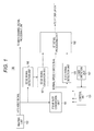
- Fig. 1 is an exemplary configuration of a camera device 100 as an embodiment.
- the camera device 100 includes a control unit 101, a user operation unit 102, an imaging unit 103, a frame rate conversion unit 104, an edge signal detection unit 105, an edge signal detection unit 106, an edge signal generation unit 107, and a VF signal processing unit 108.
- the control unit (camera CPU) 101 controls the operation of each unit in the camera device 100.
- the user operation unit 102 is connected to the control unit 101 so as to form a user interface for various types of user operation.
- the imaging unit 103 includes an image sensor such as a Complementary Metal-Oxide Semiconductor (CMOS) or a Charge Coupled Device (CCD) so as to output a high-frame-rate video signal (HFR video signal).
- CMOS Complementary Metal-Oxide Semiconductor
- CCD Charge Coupled Device
- the output HFR video signal is transmitted to a main-channel signal processing unit.
- the frame rate of the HFR video signal is N times higher than the frame rate of a normal speed video signal (normal-frame-rate video signal).
- N is an integer larger than or equal to two.
- the frame rate of the normal speed video signal is 60 Hz
- the frame rate of the HFR video signal is four times higher than the frame rate and thus is 240 Hz.
- the frame rate conversion unit 104 is configured with, for example, a frame memory so as to provide a normal speed video signal at a frame rate of 60 Hz from an HFR video signal at a frame rate of 240 Hz.
- the frame rate conversion unit 104 generates a video signal of a frame of the normal speed video signal by summing the video signals of four frames every four frames in the HFR video signal.
- a video signal of a frame of the normal speed video signal can be provided every four frames in the HFR video signal with video signals of three or two frames or a video signal of a frame instead of all of the video signals of the four frames.
- Figs. 2(a1) to 2(a4) illustrate exemplary images of four frames in an HFR video signal output from the imaging unit 103.
- a "person” forms a moving part and "cylinders" form a stationary part.
- Fig. 2 (b) illustrates an exemplary image of a frame in a normal speed video signal provided by the frame rate conversion unit 104. The example illustrates that the video signals of four frames are summed in a unit of four frames in the HFR video signal so that a video signal of a frame in the normal speed video signal.
- the edge signal detection unit 105 filters each frame in the normal speed video signal at a frame rate of 60 Hz provided by the frame rate conversion unit 104 in horizontal and vertical high pass filter processes so as to detect an edge signal corresponding to each frame at the frame rate of 60 Hz.
- Fig. 3 (a) illustrates an exemplary edge signal of a frame detected with the edge signal detection unit 105.
- This example illustrates that a focused point is near the stationary part of the front "cylinder".
- the edge signal corresponding to the edge of the "cylinder” is detected (see an arrow P1).
- moving image blurring occurs because the "person” is the moving part.
- the edge signal corresponding to the edge of the "person” is not detected.
- the edge signal detection unit 106 filters each frame in the HFR video signal at a frame rate of 240 Hz output from the imaging unit 103 in horizontal and vertical high pass filter processes so as to detect an edge signal corresponding to each frame at the frame rate of 240 Hz.
- Figs. 3(b1) to 3(b4) illustrate exemplary edge signals of the four frames detected with the edge signal detection unit 106.
- FIG. 4 (a) illustrates the state in which the edge signals of the four frame detected with the edge signal detection unit 106 and illustrated in Figs. 3(b1) to 3(b4) are summed. Note that the "cylinder” and "person” are illustrated as references indicating the detection positions at which the edge signals (difference absolute values) are detected in Figs.3(a), 3(b1) to 3(b4) , and 4(a) .
- the edge signal generation unit 107 performs an arithmetic process to find the difference absolute value between the edge signals of each frame and the adjacent frame, using the edge signal of each frame detected with the edge signal detection unit 106. Taking the difference absolute values as described above can offset and remove the edge signals corresponding to the stationary part.
- Figs. 4(b1) to 4(b4) illustrates exemplary difference absolute values among the four frames generated with the edge signal generation unit 107.
- the edge signals corresponding to the edge of the "cylinder” that is the stationary part are removed and the edge signals corresponding to the edge of the "person” that is the moving part remain as illustrated in the drawings (see arrows Q1', Q2' , and Q3').
- the "cylinder” and "person” are illustrated as references indicating the detection positions at which the edge signals (difference absolute values) are detected in Figs. 4(b1) to 4(b4) .
- the edge signal generation unit 107 sums the difference absolute values of the four frames every four frames, and generates an edge signal corresponding to each frame at a frame rate of 60 Hz. Note that the edge signal generation unit 107 can generate the edge signal of a frame every four frames using the difference absolute values of three or two frames, or the difference absolute value of a frame instead of all of the difference absolute values of the four frames.
- the VF signal processing unit 108 synthesizes the edge signal corresponding to each frame at a frame rate of 60 Hz and generated with the edge signal generation unit 107 onto the normal speed video signal at a frame rate of 60 Hz provided by the frame rate conversion unit 104 so as to generate a first video signal for a viewfinder display.
- the VF signal processing unit 108 synthesizes the edge signal onto the video signal so that the edge is highlighted (for example, by a bright display or a display with a predetermined color including white).
- the VF signal processing unit 108 converts the edge signal into a color signal of a predetermined color and synthesizes the color signal onto the video signal.
- the VF signal processing unit 108 determines the predetermined color in accordance with the selection signal from the user operation unit 102. In other words, the user can set the color that the user desires as the predetermined color by operating the user operation unit 102.
- the VF signal processing unit 108 synthesizes the edge signal corresponding to each frame at a frame rate of 60 Hz and detected with the edge signal detection unit 105 onto the normal speed video signal at a frame rate of 60 Hz provided by the frame rate conversion unit 104 so as to generate a second video signal for a viewfinder display.
- the VF signal processing unit 108 synthesizes the edge signal onto the video signal so that the edge is highlighted (for example, by a bright display or a display with a predetermined color including white).
- the VF signal processing unit 108 synthesizes both of the edge signal corresponding to each frame at a frame rate of 60 Hz and generated with the edge signal generation unit 107 (the first edge signal) and the edge signal corresponding to each frame at a frame rate of 60 Hz and detected with the edge signal detection unit 105 (the second edge signal) onto the normal speed video signal at a frame rate of 60 Hz provided by the frame rate conversion unit 104 so as to generate a third video signal for a viewfinder display.
- the VF signal processing unit 108 synthesizes the edge signal onto the video signal so that the edge is highlighted (for example, by a bright display or a display with a predetermined color including white) .
- the VF signal processing unit 108 can distinguish the highlighted edge with the first edge signal from the highlighted edge with the second edge signal by changing the color phases.
- the VF signal processing unit 108 outputs one of the first video signal, the second video signal, and the third video signal and transmits the output signal to a VF display unit (the viewfinder).
- the VF signal processing unit 108 determines the video signal for a viewfinder display to be output in accordance with the selection signal from the user operation unit 102.
- the user can set the video signal for a viewfinder display to be transmitted to the VF display unit (the viewfinder) by operating the user operation unit 102.
- An HFR video signal at a frame rate of 240 Hz is provided from the imaging unit 103 (see Figs. 2 (a1) to 2 (a4)).
- the HFR video signal is transmitted to the main-channel signal processing unit and provided to the frame rate conversion unit 104 and the edge signal detection unit 106.
- the frame rate conversion unit 104 coverts the frame rates in a conversion process so that a normal speed video signal at a frame rate of 60 Hz is acquired from the HFR video signal at a frame rate of 240 Hz (see Fig. 2(b) ).
- the acquired normal speed video signal is provided to the edge signal detection unit 105 and the VF signal processing unit 108.
- the edge signal detection unit 105 filters each frame in the normal speed video signal at a frame rate of 60 Hz in horizontal and vertical high pass filter processes so as to detect an edge signal corresponding to each frame at a frame rate of 60 Hz (see Fig. 3(a) ).
- the detected edge signal is provided to the VF signal processing unit 108.
- the edge signal detection unit 106 filters each frame in the HFR video signal at a frame rate of 240 Hz in horizontal and vertical high pass filter processes so as to detect an edge signal corresponding to each frame at a frame rate of 240 Hz (see Figs. 3(b1) to 3 (b4)).
- the detected edge signal is provided to the edge signal generation unit 107.
- the edge signal generation unit 107 finds the difference absolute value between the edge signals of each frame and the adjacent frame, using the edge signal of each frame (see Figs. 4(b1) to 4(b4) ). Then, the edge signal generation unit 107 generates an edge signal corresponding to each frame at a frame rate of 60 Hz by summing the difference absolute values of the four frames every four frames. The generated edge signal is provided to the VF signal processing unit 108.
- the VF signal processing unit 108 synthesizes the edge signal corresponding to each frame at a frame rate of 60 Hz and generated with the edge signal generation unit 107 onto the normal speed video signal at a frame rate of 60 Hz provided by the frame rate conversion unit 104 so as to generate the first video signal for a viewfinder display.
- the VF signal processing unit 108 synthesizes the edge signal onto the video signal so that the edge is highlighted (for example, by a bright display or a display with a predetermined color including white).
- the VF signal processing unit 108 synthesizes the edge signal corresponding to each frame at a frame rate of 60 Hz and detected with the edge signal detection unit 105 onto the normal speed video signal at a frame rate of 60 Hz provided by the frame rate conversion unit 104 so as to generate the second video signal for a viewfinder display.
- the VF signal processing unit 108 synthesizes the edge signal onto the video signal so that the edge is highlighted (for example, by a bright display or a display with a predetermined color including white).
- the VF signal processing unit 108 synthesizes both of the edge signal corresponding to each frame at a frame rate of 60 Hz and generated with the edge signal generation unit 107 (the first edge signal) and the edge signal corresponding to each frame at a frame rate of 60 Hz and detected with the edge signal detection unit 105 (the second edge signal) onto the normal speed video signal at a frame rate of 60 Hz provided by the frame rate conversion unit 104 so as to generate a third video signal for a view finder display.
- the VF signal processing unit 108 synthesizes the edge signals onto the video signal so that the edge is highlighted (for example, by a bright display or a display with a predetermined color including white).
- the VF signal processing unit 108 selectively outputs one of the first video signal, the second video signal, and the third video signal, for example, in response to the user's selection operation. As described above, the video signal for a viewfinder display output from the VF signal processing unit 108 is transmitted to the VF display unit (the viewfinder).
- Fig. 5 (a) illustrates an exemplary image of a frame of the first video signal for a viewfinder display to be displayed in the viewfinder. This example illustrates that a focused point is near the stationary part of the front "cylinder". As illustrated in the drawing, only the edge of the "person” that is the moving part is highlighted (see an arrow R1).
- Fig. 5(b) illustrates an exemplary image of a frame of the second video signal for a viewfinder display to be displayed in the viewfinder. This example illustrates that a focused point is near the stationary part of the front "cylinder". As illustrated in the drawing, only the edge of the "cylinder" that is the stationary part is highlighted (see an arrow R2).
- Fig. 5(c) illustrates an exemplary image of a frame of the third video signal for a viewfinder display to be displayed in the viewfinder.
- This example illustrates that a focused point is near the stationary part of the front "cylinder".
- both of the edge of the "person” that is the moving part and the edge of the "cylinder” that is the stationary part are highlighted (see arrows R1 and R2).
- the camera device 100 illustrated in Fig. 1 provides the video signal (the first video signal) for a viewfinder display by generating an edge signal corresponding to each frame at a frame rate of 60 Hz in accordance with the edge signal detected in each frame of the HFR video signal at a frame rate of 240 Hz and synthesizing the generated edge signal onto the normal speed video signal at a frame rate of 60 Hz.
- This can, for example, prevent the effect of moving image blurring, and can provide the edge signal of the moving part as the edge signal corresponding to each frame at a frame rate of 60 Hz with good condition.
- the edge of the moving part can also be highlighted with the edge signal.
- the camera device 100 illustrated in Fig. 1 finds the difference absolute value between the edge signals of each frame and the adjacent frame, using the edge signal detected in each frame of the HFR video signal at a frame rate of 240 Hz, and then generates the edge signal of a frame from some or all of the difference absolute values of the edge signals of the frames every four frames. This enables, for example, an edge highlight display corresponding only to the edge of the moving part.
- the VF signal processing unit 108 in the camera device 100 illustrated in Fig. 1 generates the first, second, and third video signals as a video signal for a viewfinder display and selectively outputs one of the first, second, and third video signals. This enables the camera device 100, for example, to display an image in which only the edge of the moving part, only the edge of the stationary part, or both edges of the parts are highlighted by the edge highlight display with the edge signals in the viewfinder.
- the edge signal generation unit 107 in the embodiment finds the difference absolute value between the edge signals of each frame and the adjacent frame, using the edge signal detected in each frame of the HFR video signal at a frame rate of 240 Hz, and then generates the edge signal of a frame from some or all of the difference absolute values of the edge signals of the frames every four frames.
- the edge signal generation unit 107 can also generate the edge signal of a frame from some or all of the absolute values of the edge signals of the frames every four frames, using the edge signal detected in each frame of the HFR video signal at a frame rate of 240 Hz.
- the generated edge signal includes the edge signal corresponding to the edge of the stationary part in addition to the edge signal corresponding to the edge of the moving part (see Fig. 4(a) ).
- the first video signal for a viewfinder display provided in this exemplary variation by synthesizing the edge signal corresponding to each frame at a frame rate of 60 Hz and generated with the edge signal generation unit 107 onto the normal speed video signal of at a frame rate of 60 Hz provided by the frame rate conversion unit 104 generated with the VF signal processing unit 108 is identical to the third video signal described in the embodiment.
- the normal frame rate using the present technology is not limited to 60 Hz, and can be, for example, 59.94 Hz or 50 Hz.
- the present technology can have the configuration described below.
Abstract
Description
- The present technology relates to a video signal processing device, a video signal processing method, and a camera device and, in particular, relates to a video signal processing device that processes a high-frame-rate video signal.
- Camera devices that can capture a video at a high frame rate have been proposed (for example, see Patent Document 1). The camera device acquires a video signal for a viewfinder display by converting the high-frame-rate video signal into a normal-frame-rate video signal (a normal speed video signal).
- A function to highlight the edge signal (high-frequency components) extracted from the video signal for a viewfinder display in order to use the edge signal as a marker to facilitate the operation of manually bringing the camera into focus with the viewfinder (for example, the PEAKING function, or the VF-DETAIL function) has been known (for example, see Patent Document 2). Using this technique can check whether the camera is in focus by checking the highlighted edge because there is a drastic change in the signal level of the part in focus (edge).
-
- Patent Document 1: Japanese Patent Application Laid-Open No.
2010-268354 - Patent Document 2: Japanese Patent Application Laid-Open No.
2007-060328 - Moving image blurring occurs in the part that moves fast on a screen. Thus, there is a loss of the edge signal (high-frequency components) in the video signal for a viewfinder display. This makes it difficult to detect the edge signal (high-frequency components) and check from the highlight of the edge signal whether the fast moving part is in focus. Note that, however, there is a need to make especially the moving part come into focus because the edge signal is used in the camera device capable of capturing a video at a high frame rate in order to show the part moving fast in slow motion.
- An objective of the present technology is to allow for easily checking whether a moving part is in focus.
- A concept of the present technology lies in a video signal processing device including:
- an edge signal detection unit that detects an edge signal by filtering each frame in a video signal at a second frame rate N times higher than a first frame rate in horizontal and vertical high pass filter processes, the N being an integer larger than or equal to two; and
- an edge signal generation unit that generates an edge signal corresponding to each frame at the first frame rate in accordance with an edge signal of each frame detected with the edge signal detection unit.
- The edge signal detection unit according to the present technology filters each frame of a video signal at a second frame rate N times higher than a first frame rate in horizontal and vertical high pass filter processes so as to detect an edge signal. N is an integer larger than or equal to two. The edge signal generation unit generates an edge signal corresponding to each frame at the first frame rate in accordance with the edge signal of each frame detected with the edge signal detection unit. For example, the second frame rate can be 200 Hz.
- Further, for example, the edge signal generation unit may perform an arithmetic process to find a difference absolute value between the edge signals of each frame and an adjacent frame, using the edge signal of each frame detected with the edge signal detection unit, and generate an edge signal of a frame from some or all of the difference absolute values of the edge signals of the frames every N frames. Further, for example, the edge signal generation unit may generate an edge signal of a frame from some or all of the edge signals of the frames every N frames, using the edge signal of each frame detected with the edge signal detection unit.
- According to the present technology, an edge signal corresponding to each frame at the first frame rate (the normal frame rate) is generated in accordance with the edge signal detected in each frame in the video signal at the second frame rate (the high frame rate). This generation can prevent, for example, the effect of moving image blurring. Thus, the edge signal corresponding to the edge of the moving part as the edge signal corresponding to each frame at the first frame rate in good condition.
- In the present technology, the video signal processing device may further include: a color conversion unit that converts an edge signal of each frame generated with the edge signal generation unit into a color signal of a predetermined color and outputs the color signal. This color conversion unit enables an edge highlight display with the predetermined color, using the edge signal.
- Another concept of the present technology lies in a camera device including:
- a frame rate conversion unit that provides a video signal at a first frame rate from a captured video signal at a second frame rate N times higher than the first frame rate, the N being an integer larger than or equal to two;
- an edge signal detection unit that detects an edge signal by filtering each frame in the captured video signal at the second frame rate in horizontal and vertical high pass filter processes;
- an edge signal generation unit that generates an edge signal corresponding to each frame at the first frame rate in accordance with the edge signal of each frame detected with the edge signal detection unit; and
- a signal synthesis unit that provides a video signal at the first frame rate for a viewfinder display by synthesizing an edge signal corresponding to each frame at the first frame rate and generated with the edge signal generation unit onto the video signal at the first frame rate provided by the frame rate conversion unit.
- The frame rate conversion unit according to the present technology provides a video signal at a first frame rate from a captured video signal at a second frame rate N times higher than the first frame rate. N is an integer larger than or equal to two. For example, the second frame rate can be higher than or equal to 200 Hz.
- The edge signal detection unit filters each frame in the captured video signal at the second frame rate in horizontal and vertical high pass filter processes so as to detect an edge signal. The edge signal generation unit generates an edge signal corresponding to each frame at the first frame rate in accordance with the edge signal of each frame detected with the edge signal detection unit.
- For example, the edge signal generation unit may perform an arithmetic process to find a difference absolute value between the edge signals of each frame and an adj acent frame, using the edge signal of each frame detected with the edge signal detection unit, and generate an edge signal of a frame from some or all of the difference absolute values of the edge signals of the frames every N frames. Further, for example, the edge signal generation unit may generate an edge signal of a frame from some or all of the edge signals of the frames every N frames, using the edge signal of each frame detected with the edge signal detection unit.
- The signal synthesis unit provides a video signal at the first frame rate for a viewfinder display by synthesizing the edge signal corresponding to each frame at the first frame rate and generated with the edge signal generation unit onto the video signal at the first frame rate provided by the frame rate conversion unit.
- According to the present technology, an edge signal corresponding to each frame at the first frame rate (the normal frame rate) is generated in accordance with the edge signal detected in each frame in the video signal at the second frame rate (the high frame rate). The generated edge signal is synthesized onto the video signal at the first frame rate. This synthesis provides a video signal for a viewfinder display. Thus, for example, the effect of moving image blurring can be prevented. The edge signal of the moving part can be provided as the edge signal corresponding to each frame at the first frame rate in good condition. Thus, the edge of the moving part can also be highlighted with the edge signal in good condition.
- In the present technology, for example, the camera device may further include: a color conversion unit that converts an edge signal of each frame generated with the edge signal generation unit into a color signal of a predetermined color and outputs the color signal, and the signal synthesis unit may provide a video signal at the first frame rate for a viewfinder display by synthesizing the color signal of the predetermined color corresponding to each frame at the first frame rate and output from the color conversion unit onto the video signal at the first frame rate provided by the frame rate conversion unit. In this example, the color conversion unit can determine the predetermined color, for example, in accordance with a selection signal from the user operation unit. The display of the edge information with the edge signal can be performed, for example, with the predetermined color selected by the user.
- Further, another concept of the present technology lies in a camera device including:
- a frame rate conversion unit that provides a video signal at a first frame rate from a captured video signal at a second frame rate N times higher than the first frame rate, the N being an integer larger than or equal to two;
- a first edge signal detection unit that detects an edge signal by filtering each frame in the captured video signal at the second frame rate in horizontal and vertical high pass filter processes;
- an edge signal generation unit that generates a first edge signal corresponding to each frame at the first frame rate in accordance with the edge signal of each frame detected with the first edge signal detection unit;
- a second edge signal detection unit that detects a second edge signal corresponding to each frame at the first frame rate by filtering each frame in the video signal at the first frame rate providedby the frame rate conversion unit in horizontal and vertical high pass filter processes; and
- a signal processing unit that outputs a video signal at the first frame rate for a viewfinder display by synthesizing the first edge signal generated with the edge signal generation unit, the second edge signal detected with the second edge signal detection unit, or a third edge signal provided by combining the first edge signal and the second edge signal onto a video signal at the first frame rate provided by the frame rate conversion unit.
- The frame rate conversion unit according to the present technology provides a video signal at a first frame rate from a captured video signal at a second frame rate N times higher than the first frame rate. N is an integer larger than or equal to two. For example, the second frame rate can be higher than or equal to 200 Hz. The first edge signal detection unit filters each frame in the captured video signal at the second frame rate in horizontal and vertical high pass filter processes so as to detect an edge signal.
- The edge signal generation unit generates a first edge signal corresponding to each frame at the first frame rate in accordance with the edge signal of each frame detected with the first edge signal detection unit. The second edge signal detection unit filters each frame in the video signal at the first frame rate provided by the frame rate conversion unit in horizontal and vertical high pass filter processes so as to detect a second edge signal corresponding to each frame at the first frame rate.
- The signal processing unit outputs a video signal at the first frame rate for a viewfinder display by synthesizing the first edge signal, the second edge signal, or a third edge signal provided by combining the first edge signal and the second edge signal onto the video signal at the first frame rate provided by the frame rate conversion unit. For example, the signal processing unit may selectively output one of the first edge signal, the second edge signal, and the third edge signal in accordance with a selection signal from a user operation unit.
- As described above according to the present technology, the first edge signal, the second edge signal, or the third edge signal provided by combining the first edge signal and the second edge signal is synthesized onto the video signal at the first frame rate. The synthesized signal is output as a video signal at the first frame rate for a viewfinder display. Thus, an image in which the edge of only the moving part, the edge of only the stationary part, or both edges of the parts are highlighted by the edge highlight display with the edge signals can be displayed in the viewfinder.
- According to the present technology, whether the moving part is in focus can be easily checked. Note that the effects described herein are merely examples and the effects of the present technology are not limited to the described effects. The present technology can have an additional effect.
-
-
Fig. 1 is a block diagram of an exemplary configuration of a camera device as an embodiment. -
Figs. 2(a1) to 2(b) are explanatory diagrams of HFR video signals and normal speed video signals. -
Figs. 3 (a) to 3 (b4) are explanatory diagrams of a process for detecting and generating an edge signal. -
Figs. 4 (a) to 4 (b4) are explanatory diagrams of a process for detecting and generating an edge signal. -
Figs. 5(a) to 5(c) are diagrams of an exemplary image shown in a viewfinder. - The mode for carrying out the invention (hereinafter, referred to as an "embodiment") will be described hereinafter. Note that the embodiment will be described in the following order.
- 1. Embodiment
- 2. Exemplary Variation
-
Fig. 1 is an exemplary configuration of acamera device 100 as an embodiment. Thecamera device 100 includes acontrol unit 101, auser operation unit 102, animaging unit 103, a framerate conversion unit 104, an edgesignal detection unit 105, an edge signal detection unit 106, an edgesignal generation unit 107, and a VFsignal processing unit 108. - The control unit (camera CPU) 101 controls the operation of each unit in the
camera device 100. Theuser operation unit 102 is connected to thecontrol unit 101 so as to form a user interface for various types of user operation. - The
imaging unit 103 includes an image sensor such as a Complementary Metal-Oxide Semiconductor (CMOS) or a Charge Coupled Device (CCD) so as to output a high-frame-rate video signal (HFR video signal). The output HFR video signal is transmitted to a main-channel signal processing unit. The frame rate of the HFR video signal is N times higher than the frame rate of a normal speed video signal (normal-frame-rate video signal). N is an integer larger than or equal to two. In the present embodiment, the frame rate of the normal speed video signal is 60 Hz, and the frame rate of the HFR video signal is four times higher than the frame rate and thus is 240 Hz. - The frame
rate conversion unit 104 is configured with, for example, a frame memory so as to provide a normal speed video signal at a frame rate of 60 Hz from an HFR video signal at a frame rate of 240 Hz. In the example, the framerate conversion unit 104 generates a video signal of a frame of the normal speed video signal by summing the video signals of four frames every four frames in the HFR video signal. Note that a video signal of a frame of the normal speed video signal can be provided every four frames in the HFR video signal with video signals of three or two frames or a video signal of a frame instead of all of the video signals of the four frames. -
Figs. 2(a1) to 2(a4) illustrate exemplary images of four frames in an HFR video signal output from theimaging unit 103. InFigs. 2(a1) to 2(a4) , a "person" forms a moving part and "cylinders" form a stationary part.Fig. 2 (b) illustrates an exemplary image of a frame in a normal speed video signal provided by the framerate conversion unit 104. The example illustrates that the video signals of four frames are summed in a unit of four frames in the HFR video signal so that a video signal of a frame in the normal speed video signal. - The edge
signal detection unit 105 filters each frame in the normal speed video signal at a frame rate of 60 Hz provided by the framerate conversion unit 104 in horizontal and vertical high pass filter processes so as to detect an edge signal corresponding to each frame at the frame rate of 60 Hz.Fig. 3 (a) illustrates an exemplary edge signal of a frame detected with the edgesignal detection unit 105. - This example illustrates that a focused point is near the stationary part of the front "cylinder". The edge signal corresponding to the edge of the "cylinder" is detected (see an arrow P1). However, moving image blurring occurs because the "person" is the moving part. Thus, the edge signal corresponding to the edge of the "person" is not detected.
- The edge signal detection unit 106 filters each frame in the HFR video signal at a frame rate of 240 Hz output from the
imaging unit 103 in horizontal and vertical high pass filter processes so as to detect an edge signal corresponding to each frame at the frame rate of 240 Hz.Figs. 3(b1) to 3(b4) illustrate exemplary edge signals of the four frames detected with the edge signal detection unit 106. - This example illustrates that a focused point is near the stationary part of the front "cylinder". The edge signal corresponding to the edge of the "cylinder" is detected (see the arrow P1). Meanwhile, the high frame rate decreases the moving image blurring, and thus the edge signals corresponding to the edge of the "person" are also detected (see arrows Q1, Q2, and Q3).
Fig. 4 (a) illustrates the state in which the edge signals of the four frame detected with the edge signal detection unit 106 and illustrated inFigs. 3(b1) to 3(b4) are summed. Note that the "cylinder" and "person" are illustrated as references indicating the detection positions at which the edge signals (difference absolute values) are detected inFigs.3(a), 3(b1) to 3(b4) , and4(a) . - The edge
signal generation unit 107 performs an arithmetic process to find the difference absolute value between the edge signals of each frame and the adjacent frame, using the edge signal of each frame detected with the edge signal detection unit 106. Taking the difference absolute values as described above can offset and remove the edge signals corresponding to the stationary part. -
Figs. 4(b1) to 4(b4) illustrates exemplary difference absolute values among the four frames generated with the edgesignal generation unit 107. The edge signals corresponding to the edge of the "cylinder" that is the stationary part are removed and the edge signals corresponding to the edge of the "person" that is the moving part remain as illustrated in the drawings (see arrows Q1', Q2' , and Q3'). Note that the "cylinder" and "person" are illustrated as references indicating the detection positions at which the edge signals (difference absolute values) are detected inFigs. 4(b1) to 4(b4) . - The edge
signal generation unit 107 sums the difference absolute values of the four frames every four frames, and generates an edge signal corresponding to each frame at a frame rate of 60 Hz. Note that the edgesignal generation unit 107 can generate the edge signal of a frame every four frames using the difference absolute values of three or two frames, or the difference absolute value of a frame instead of all of the difference absolute values of the four frames. - The VF
signal processing unit 108 synthesizes the edge signal corresponding to each frame at a frame rate of 60 Hz and generated with the edgesignal generation unit 107 onto the normal speed video signal at a frame rate of 60 Hz provided by the framerate conversion unit 104 so as to generate a first video signal for a viewfinder display. In this example, the VFsignal processing unit 108 synthesizes the edge signal onto the video signal so that the edge is highlighted (for example, by a bright display or a display with a predetermined color including white). - For example, in order to display the edge with a predetermined color, the VF
signal processing unit 108 converts the edge signal into a color signal of a predetermined color and synthesizes the color signal onto the video signal. In this example, the VFsignal processing unit 108 determines the predetermined color in accordance with the selection signal from theuser operation unit 102. In other words, the user can set the color that the user desires as the predetermined color by operating theuser operation unit 102. - The VF
signal processing unit 108 synthesizes the edge signal corresponding to each frame at a frame rate of 60 Hz and detected with the edgesignal detection unit 105 onto the normal speed video signal at a frame rate of 60 Hz provided by the framerate conversion unit 104 so as to generate a second video signal for a viewfinder display. In this example, the VFsignal processing unit 108 synthesizes the edge signal onto the video signal so that the edge is highlighted (for example, by a bright display or a display with a predetermined color including white). - The VF
signal processing unit 108 synthesizes both of the edge signal corresponding to each frame at a frame rate of 60 Hz and generated with the edge signal generation unit 107 (the first edge signal) and the edge signal corresponding to each frame at a frame rate of 60 Hz and detected with the edge signal detection unit 105 (the second edge signal) onto the normal speed video signal at a frame rate of 60 Hz provided by the framerate conversion unit 104 so as to generate a third video signal for a viewfinder display. - In this example, the VF
signal processing unit 108 synthesizes the edge signal onto the video signal so that the edge is highlighted (for example, by a bright display or a display with a predetermined color including white) . For example, in order to display the edge with a predetermined color, the VFsignal processing unit 108 can distinguish the highlighted edge with the first edge signal from the highlighted edge with the second edge signal by changing the color phases. - Then, the VF
signal processing unit 108 outputs one of the first video signal, the second video signal, and the third video signal and transmits the output signal to a VF display unit (the viewfinder). In this example, the VFsignal processing unit 108 determines the video signal for a viewfinder display to be output in accordance with the selection signal from theuser operation unit 102. In other words, the user can set the video signal for a viewfinder display to be transmitted to the VF display unit (the viewfinder) by operating theuser operation unit 102. - The operation of the
camera device 100 illustrated inFig. 1 will brief ly be described. An HFR video signal at a frame rate of 240 Hz is provided from the imaging unit 103 (seeFigs. 2 (a1) to 2 (a4)). The HFR video signal is transmitted to the main-channel signal processing unit and provided to the framerate conversion unit 104 and the edge signal detection unit 106. - The frame
rate conversion unit 104 coverts the frame rates in a conversion process so that a normal speed video signal at a frame rate of 60 Hz is acquired from the HFR video signal at a frame rate of 240 Hz (seeFig. 2(b) ). The acquired normal speed video signal is provided to the edgesignal detection unit 105 and the VFsignal processing unit 108. - The edge
signal detection unit 105 filters each frame in the normal speed video signal at a frame rate of 60 Hz in horizontal and vertical high pass filter processes so as to detect an edge signal corresponding to each frame at a frame rate of 60 Hz (seeFig. 3(a) ). The detected edge signal is provided to the VFsignal processing unit 108. - The edge signal detection unit 106 filters each frame in the HFR video signal at a frame rate of 240 Hz in horizontal and vertical high pass filter processes so as to detect an edge signal corresponding to each frame at a frame rate of 240 Hz (see
Figs. 3(b1) to 3 (b4)). The detected edge signal is provided to the edgesignal generation unit 107. - The edge
signal generation unit 107 finds the difference absolute value between the edge signals of each frame and the adjacent frame, using the edge signal of each frame (seeFigs. 4(b1) to 4(b4) ). Then, the edgesignal generation unit 107 generates an edge signal corresponding to each frame at a frame rate of 60 Hz by summing the difference absolute values of the four frames every four frames. The generated edge signal is provided to the VFsignal processing unit 108. - The VF
signal processing unit 108 synthesizes the edge signal corresponding to each frame at a frame rate of 60 Hz and generated with the edgesignal generation unit 107 onto the normal speed video signal at a frame rate of 60 Hz provided by the framerate conversion unit 104 so as to generate the first video signal for a viewfinder display. In this example, the VFsignal processing unit 108 synthesizes the edge signal onto the video signal so that the edge is highlighted (for example, by a bright display or a display with a predetermined color including white). - The VF
signal processing unit 108 synthesizes the edge signal corresponding to each frame at a frame rate of 60 Hz and detected with the edgesignal detection unit 105 onto the normal speed video signal at a frame rate of 60 Hz provided by the framerate conversion unit 104 so as to generate the second video signal for a viewfinder display. In this example, the VFsignal processing unit 108 synthesizes the edge signal onto the video signal so that the edge is highlighted (for example, by a bright display or a display with a predetermined color including white). - The VF
signal processing unit 108 synthesizes both of the edge signal corresponding to each frame at a frame rate of 60 Hz and generated with the edge signal generation unit 107 (the first edge signal) and the edge signal corresponding to each frame at a frame rate of 60 Hz and detected with the edge signal detection unit 105 (the second edge signal) onto the normal speed video signal at a frame rate of 60 Hz provided by the framerate conversion unit 104 so as to generate a third video signal for a view finder display. In this example, the VFsignal processing unit 108 synthesizes the edge signals onto the video signal so that the edge is highlighted (for example, by a bright display or a display with a predetermined color including white). - The VF
signal processing unit 108 selectively outputs one of the first video signal, the second video signal, and the third video signal, for example, in response to the user's selection operation. As described above, the video signal for a viewfinder display output from the VFsignal processing unit 108 is transmitted to the VF display unit (the viewfinder). -
Fig. 5 (a) illustrates an exemplary image of a frame of the first video signal for a viewfinder display to be displayed in the viewfinder. This example illustrates that a focused point is near the stationary part of the front "cylinder". As illustrated in the drawing, only the edge of the "person" that is the moving part is highlighted (see an arrow R1). -
Fig. 5(b) illustrates an exemplary image of a frame of the second video signal for a viewfinder display to be displayed in the viewfinder. This example illustrates that a focused point is near the stationary part of the front "cylinder". As illustrated in the drawing, only the edge of the "cylinder" that is the stationary part is highlighted (see an arrow R2). -
Fig. 5(c) illustrates an exemplary image of a frame of the third video signal for a viewfinder display to be displayed in the viewfinder. This example illustrates that a focused point is near the stationary part of the front "cylinder". As illustrated in the drawing, both of the edge of the "person" that is the moving part and the edge of the "cylinder" that is the stationary part are highlighted (see arrows R1 and R2). - The
camera device 100 illustrated inFig. 1 provides the video signal (the first video signal) for a viewfinder display by generating an edge signal corresponding to each frame at a frame rate of 60 Hz in accordance with the edge signal detected in each frame of the HFR video signal at a frame rate of 240 Hz and synthesizing the generated edge signal onto the normal speed video signal at a frame rate of 60 Hz. This can, for example, prevent the effect of moving image blurring, and can provide the edge signal of the moving part as the edge signal corresponding to each frame at a frame rate of 60 Hz with good condition. Thus, the edge of the moving part can also be highlighted with the edge signal. - The
camera device 100 illustrated inFig. 1 finds the difference absolute value between the edge signals of each frame and the adjacent frame, using the edge signal detected in each frame of the HFR video signal at a frame rate of 240 Hz, and then generates the edge signal of a frame from some or all of the difference absolute values of the edge signals of the frames every four frames. This enables, for example, an edge highlight display corresponding only to the edge of the moving part. - The VF
signal processing unit 108 in thecamera device 100 illustrated inFig. 1 generates the first, second, and third video signals as a video signal for a viewfinder display and selectively outputs one of the first, second, and third video signals. This enables thecamera device 100, for example, to display an image in which only the edge of the moving part, only the edge of the stationary part, or both edges of the parts are highlighted by the edge highlight display with the edge signals in the viewfinder. - Note that the edge
signal generation unit 107 in the embodiment finds the difference absolute value between the edge signals of each frame and the adjacent frame, using the edge signal detected in each frame of the HFR video signal at a frame rate of 240 Hz, and then generates the edge signal of a frame from some or all of the difference absolute values of the edge signals of the frames every four frames. However, the edgesignal generation unit 107 can also generate the edge signal of a frame from some or all of the absolute values of the edge signals of the frames every four frames, using the edge signal detected in each frame of the HFR video signal at a frame rate of 240 Hz. - In this exemplary variation, the generated edge signal includes the edge signal corresponding to the edge of the stationary part in addition to the edge signal corresponding to the edge of the moving part (see
Fig. 4(a) ). Thus, the first video signal for a viewfinder display provided in this exemplary variation by synthesizing the edge signal corresponding to each frame at a frame rate of 60 Hz and generated with the edgesignal generation unit 107 onto the normal speed video signal of at a frame rate of 60 Hz provided by the framerate conversion unit 104 generated with the VFsignal processing unit 108 is identical to the third video signal described in the embodiment. - To simplify the description, the example in which the normal frame rate is 60 Hz has been described in the embodiment. However, the normal frame rate using the present technology is not limited to 60 Hz, and can be, for example, 59.94 Hz or 50 Hz.
- Furthermore, the present technology can have the configuration described below.
- (1) A video signal processing device including:
- an edge signal detection unit that detects an edge signal by filtering each frame in a video signal at a second frame rate N times higher than a first frame rate in horizontal and vertical high pass filter processes, the N being an integer larger than or equal to two; and
- an edge signal generation unit that generates an edge signal corresponding to each frame at the first frame rate in accordance with an edge signal of each frame detected with the edge signal detection unit.
- (2) The video signal processing device according to (1), wherein the edge signal generation unit
performs an arithmetic process to find a difference absolute value between the edge signals of each frame and an adjacent frame, using the edge signal of each frame detected with the edge signal detection unit, and
generates an edge signal of a frame from some or all of the difference absolute values of the edge signals of the frames every N frames. - (3) The video signal processing device according to (1), wherein the edge signal generation unit
generates an edge signal of a frame from some or all of the edge signals of the frames every N frames, using the edge signal of each frame detected with the edge signal detection unit. - (4) The video signal processing device according to any of (1) to (3), further including:
- a color conversion unit that converts an edge signal of each frame generated with the edge signal generation unit into a color signal of a predetermined color and outputs the color signal.
- (5) The video signal processing device according to any of (1) to (4), wherein the second frame rate is higher than or equal to 200 Hz.
- (6) A video signal processing method, the method including:
- an edge signal detecting step that detects an edge signal by filtering each frame in a video signal at a second frame rate N times higher than a first frame rate in horizontal and vertical high pass filter processes with a high pass filter, the N being an integer larger than or equal to two; and
- an edge signal generating step that generates an edge signal corresponding to each frame at the first frame rate in accordance with an edge signal of each frame detected in the edge signal detecting step.
- (7) A camera device including:
- a frame rate conversion unit that provides a video signal at a first frame rate from a captured video signal at a second frame rate N times higher than the first frame rate, the N being an integer larger than or equal to two;
- an edge signal detection unit that detects an edge signal by filtering each frame in the captured video signal at the second frame rate in horizontal and vertical high pass filter processes;
- an edge signal generation unit that generates an edge signal corresponding to each frame at the first frame rate in accordance with the edge signal of each frame detected with the edge signal detection unit; and
- a signal synthesis unit that provides a video signal at the first frame rate for a viewfinder display by synthesizing an edge signal corresponding to each frame at the first frame rate and generated with the edge signal generation unit onto the video signal at the first frame rate provided by the frame rate conversion unit.
- (8) The camera device according to (7), wherein the edge signal generation unit
performs an arithmetic process to find a difference absolute value between the edge signals of each frame and an adjacent frame, using the edge signal of each frame detected with the edge signal detection unit, and
generates an edge signal of a frame from some or all of the difference absolute values of the edge signals of the frames every N frames. - (9) The camera device according to (7), wherein the edge signal generation unit
generates an edge signal of a frame from some or all of the edge signals of the frames every N frames, using the edge signal of each frame detected with the edge signal detection unit. - (10) The camera device according to any of (7) to (9), further including:
- a color conversion unit that converts an edge signal of each frame generated with the edge signal generation unit into a color signal of a predetermined color and outputs the color signal,
- wherein the signal synthesis unit
- provides a video signal at the first frame rate for a viewfinder display by synthesizing the color signal of the predetermined color corresponding to each frame at the first frame rate and output from the color conversion unit onto the video signal at the first frame rate provided by the frame rate conversion unit.
- (11) The camera device according to (10),
wherein the color conversion unit
determines the predetermined color in accordance with a selection signal from a user operation unit. - (12) The camera device according to any of (7) to (11), wherein the second frame rate is higher than or equal to 200 Hz.
- (13) A video signal processing method, the method including:
- a framerate converting step that provides a video signal at a first frame rate from a captured video signal at a second frame rate N times higher than the first frame rate, the N being an integer larger than or equal to two;
- an edge signal detecting step that detects an edge signal by filtering each frame in the captured video signal at the second frame rate in horizontal and vertical high pass filter processes with a high pass filter;
- an edge signal generating step that generates an edge signal corresponding to each frame at the first frame rate in accordance with the edge signal of each frame detected in the edge signal detecting step; and
- a signal synthesizing step that provides a video signal at the first frame rate for a viewfinder display by synthesizing an edge signal corresponding to each frame at the first frame rate and generated in the edge signal generating step onto the video signal at the first frame rate provided in the frame rate converting step.
- a framerate converting step that provides a video signal at a first frame rate from a captured video signal at a second frame rate N times higher than the first frame rate, the N being an integer larger than or equal to two;
- (14) A camera device including:
- a frame rate conversion unit that provides a video signal at a first frame rate from a captured video signal at a second frame rate N times higher than the first frame rate, the N being an integer larger than or equal to two;
- a first edge signal detection unit that detects an edge signal by filtering each frame in the captured video signal at the second frame rate in horizontal and vertical high pass filter processes;
- an edge signal generation unit that generates a first edge signal corresponding to each frame at the first frame rate in accordance with the edge signal of each frame detected with the first edge signal detection unit;
- a second edge signal detection unit that detects a second edge signal corresponding to each frame at the first frame rate by filtering each frame in the video signal at the first frame rate providedby the frame rate conversion unit in horizontal and vertical high pass filter processes; and
- a signal processing unit that outputs a video signal at the first frame rate for a viewfinder display by synthesizing the first edge signal generated with the edge signal generation unit, the second edge signal detected with the second edge signal detection unit, or a third edge signal provided by combining the first edge signal and the second edge signal onto a video signal at the first frame rate provided by the frame rate conversion unit. (15) The camera device according to (14), wherein the signal processing unit
- selectively outputs one of the first edge signal, the second edge signal, and the third edge signal in accordance with a selection signal from a user operation unit.
-
- 100
- Camera device
- 101
- Control unit
- 102
- User operation unit
- 103
- Imaging unit
- 104
- Frame rate conversion unit
- 105, 106
- Edge signal detection unit
- 107
- Edge signal generation unit
- 108
- VF signal processing unit
Claims (15)
- A video signal processing device comprising:an edge signal detection unit that detects an edge signal by filtering each frame in a video signal at a second frame rate N times higher than a first frame rate in horizontal and vertical high pass filter processes, the N being an integer larger than or equal to two; andan edge signal generation unit that generates an edge signal corresponding to each frame at the first frame rate in accordance with an edge signal of each frame detected with the edge signal detection unit.
- The video signal processing device according to claim 1, wherein the edge signal generation unit
performs an arithmetic process to find a difference absolute value between the edge signals of each frame and an adjacent frame, using the edge signal of each frame detected with the edge signal detection unit, and
generates an edge signal of a frame from some or all of the difference absolute values of the edge signals of the frames every N frames. - The video signal processing device according to claim 1, wherein the edge signal generation unit
generates an edge signal of a frame from some or all of the edge signals of the frames every N frames, using the edge signal of each frame detected with the edge signal detection unit. - The video signal processing device according to claim 1, further comprising:a color conversion unit that converts an edge signal of each frame generated with the edge signal generation unit into a color signal of a predetermined color and outputs the color signal.
- The video signal processing device according to claim 1, wherein the second frame rate is higher than or equal to 200 Hz.
- A video signal processing method, the method comprising:an edge signal detecting step that detects an edge signal by filtering each frame in a video signal at a second frame rate N times higher than a first frame rate in horizontal and vertical high pass filter processes with a high pass filter, the N being an integer larger than or equal to two; andan edge signal generating step that generates an edge signal corresponding to each frame at the first frame rate in accordance with an edge signal of each frame detected in the edge signal detecting step.
- A camera device comprising:a frame rate conversion unit that provides a video signal at a first frame rate from a captured video signal at a second frame rate N times higher than the first frame rate, the N being an integer larger than or equal to two;an edge signal detection unit that detects an edge signal by filtering each frame in the captured video signal at the second frame rate in horizontal and vertical high pass filter processes;an edge signal generation unit that generates an edge signal corresponding to each frame at the first frame rate in accordance with the edge signal of each frame detected with the edge signal detection unit; anda signal synthesis unit that provides a video signal at the first frame rate for a viewfinder display by synthesizing an edge signal corresponding to each frame at the first frame rate and generated with the edge signal generation unit onto the video signal at the first frame rate provided by the frame rate conversion unit.
- The camera device according to claim 7, wherein the edge signal generation unit
performs an arithmetic process to find a difference absolute value between the edge signals of each frame and an adjacent frame, using the edge signal of each frame detected with the edge signal detection unit, and
generates an edge signal of a frame from some or all of the difference absolute values of the edge signals of the frames every N frames. - The camera device according to claim 7, wherein the edge signal generation unit
generates an edge signal of a frame from some or all of the edge signals of the frames every N frames, using the edge signal of each frame detected with the edge signal detection unit. - The camera device according to claim 7, further comprising:a color conversion unit that converts an edge signal of each frame generated with the edge signal generation unit into a color signal of a predetermined color and outputs the color signal,wherein the signal synthesis unitprovides a video signal at the first frame rate for a viewfinder display by synthesizing the color signal of the predetermined color corresponding to each frame at the first frame rate and output from the color conversion unit onto the video signal at the first frame rate provided by the frame rate conversion unit.
- The camera device according to claim 10,
wherein the color conversion unit
determines the predetermined color in accordance with a selection signal from a user operation unit. - The camera device according to claim 7, wherein the second frame rate is higher than or equal to 200 Hz.
- A video signal processing method, the method comprising:a framerate converting step that provides a video signal at a first frame rate from a captured video signal at a second frame rate N times higher than the first frame rate, the N being an integer larger than or equal to two;an edge signal detecting step that detects an edge signal by filtering each frame in the captured video signal at the second frame rate in horizontal and vertical high pass filter processes with a high pass filter;an edge signal generating step that generates an edge signal corresponding to each frame at the first frame rate in accordance with the edge signal of each frame detected in the edge signal detecting step; anda signal synthesizing step that provides a video signal at the first frame rate for a viewfinder display by synthesizing an edge signal corresponding to each frame at the first frame rate and generated in the edge signal generating step onto the video signal at the first frame rate provided in the frame rate converting step.
- A camera device comprising:a frame rate conversion unit that provides a video signal at a first frame rate from a captured video signal at a second frame rate N times higher than the first frame rate, the N being an integer larger than or equal to two;a first edge signal detection unit that detects an edge signal by filtering each frame in the captured video signal at the second frame rate in horizontal and vertical high pass filter processes;an edge signal generation unit that generates a first edge signal corresponding to each frame at the first frame rate in accordance with the edge signal of each frame detected with the first edge signal detection unit;a second edge signal detection unit that detects a second edge signal corresponding to each frame at the first frame rate by filtering each frame in the video signal at the first frame rate providedby the frame rate conversion unit in horizontal and vertical high pass filter processes; anda signal processing unit that outputs a video signal at the first frame rate for a viewfinder display by synthesizing the first edge signal generated with the edge signal generation unit, the second edge signal detected with the second edge signal detection unit, or a third edge signal provided by combining the first edge signal and the second edge signal onto a video signal at the first frame rate provided by the frame rate conversion unit.
- The camera device according to claim 14, wherein the signal processing unit
selectively outputs one of the first edge signal, the second edge signal, and the third edge signal in accordance with a selection signal from a user operation unit.
Applications Claiming Priority (2)
| Application Number | Priority Date | Filing Date | Title |
|---|---|---|---|
| JP2014002202 | 2014-01-09 | ||
| PCT/JP2014/083487 WO2015104969A1 (en) | 2014-01-09 | 2014-12-17 | Video signal processing device, video signal processing method, and camera device |
Publications (3)
| Publication Number | Publication Date |
|---|---|
| EP3094079A1 true EP3094079A1 (en) | 2016-11-16 |
| EP3094079A4 EP3094079A4 (en) | 2017-08-16 |
| EP3094079B1 EP3094079B1 (en) | 2023-03-29 |
Family
ID=53523807
Family Applications (1)
| Application Number | Title | Priority Date | Filing Date |
|---|---|---|---|
| EP14877618.0A Active EP3094079B1 (en) | 2014-01-09 | 2014-12-17 | Video signal processing device, video signal processing method, and camera device |
Country Status (4)
| Country | Link |
|---|---|
| US (2) | US10469729B2 (en) |
| EP (1) | EP3094079B1 (en) |
| JP (2) | JP6443346B2 (en) |
| WO (1) | WO2015104969A1 (en) |
Families Citing this family (5)
| Publication number | Priority date | Publication date | Assignee | Title |
|---|---|---|---|---|
| WO2015104969A1 (en) * | 2014-01-09 | 2015-07-16 | ソニー株式会社 | Video signal processing device, video signal processing method, and camera device |
| US10598972B2 (en) * | 2017-12-25 | 2020-03-24 | Huizhou China Star Optoelectronics Technology Co., Ltd. | Liquid crystal panel protective cover and liquid crystal panel packaging component |
| TWI808970B (en) * | 2018-04-30 | 2023-07-21 | 圓剛科技股份有限公司 | Video signal conversion device |
| CN113574858A (en) * | 2019-03-28 | 2021-10-29 | 索尼集团公司 | Image capturing apparatus, image capturing method, and program |
| US20230088882A1 (en) * | 2021-09-22 | 2023-03-23 | Samsung Electronics Co., Ltd. | Judder detection for dynamic frame rate conversion |
Family Cites Families (22)
| Publication number | Priority date | Publication date | Assignee | Title |
|---|---|---|---|---|
| US5496106A (en) * | 1994-12-13 | 1996-03-05 | Apple Computer, Inc. | System and method for generating a contrast overlay as a focus assist for an imaging device |
| JP4031122B2 (en) * | 1998-09-30 | 2008-01-09 | 本田技研工業株式会社 | Object detection device using difference image |
| JP4592243B2 (en) * | 1999-10-04 | 2010-12-01 | 浜松ホトニクス株式会社 | High-speed image processing camera system |
| JP4228947B2 (en) | 2003-05-20 | 2009-02-25 | 日産自動車株式会社 | Imaging device |
| JP5062968B2 (en) * | 2004-08-11 | 2012-10-31 | ソニー株式会社 | Image processing apparatus and method, recording medium, and program |
| JP4836065B2 (en) | 2005-03-31 | 2011-12-14 | 株式会社国際電気通信基礎技術研究所 | Edge tracking method and computer program therefor |
| JP4325599B2 (en) | 2005-08-25 | 2009-09-02 | ソニー株式会社 | Imaging apparatus and display control method |
| JP4982997B2 (en) | 2005-10-28 | 2012-07-25 | 株式会社ニコン | Image processing device |
| JP4984915B2 (en) * | 2006-03-27 | 2012-07-25 | セイコーエプソン株式会社 | Imaging apparatus, imaging system, and imaging method |
| JP4139430B1 (en) * | 2007-04-27 | 2008-08-27 | シャープ株式会社 | Image processing apparatus and method, image display apparatus and method |
| JP2008283442A (en) * | 2007-05-10 | 2008-11-20 | Olympus Corp | Imaging apparatus |
| JP4869218B2 (en) * | 2007-12-28 | 2012-02-08 | オリンパス株式会社 | Imaging display device |
| JP4730412B2 (en) * | 2008-08-12 | 2011-07-20 | ソニー株式会社 | Image processing apparatus and image processing method |
| JP2010268354A (en) | 2009-05-18 | 2010-11-25 | Olympus Corp | Image sensor and imaging device equipped with the image sensor |
| JP4620163B2 (en) * | 2009-06-30 | 2011-01-26 | 株式会社東芝 | Still subtitle detection apparatus, video device for displaying image including still subtitle, and method for processing image including still subtitle |
| WO2011047214A2 (en) * | 2009-10-14 | 2011-04-21 | Optimum Technologies, Inc. | Portable retinal camera and image acquisition method |
| KR101630303B1 (en) * | 2010-02-02 | 2016-06-14 | 삼성전자주식회사 | Apparatus for processing digital image and thereof method |
| US9013584B2 (en) * | 2010-03-01 | 2015-04-21 | Stmicroelectronics, Inc. | Border handling for motion compensated temporal interpolator using camera model |
| JP5799690B2 (en) * | 2011-09-07 | 2015-10-28 | 株式会社リコー | Imaging apparatus and control method thereof |
| JP2013072923A (en) * | 2011-09-27 | 2013-04-22 | Sanyo Electric Co Ltd | Imaging apparatus |
| WO2015104969A1 (en) * | 2014-01-09 | 2015-07-16 | ソニー株式会社 | Video signal processing device, video signal processing method, and camera device |
| BR112016018702A2 (en) | 2014-02-21 | 2017-08-08 | Taleris Global Llp | METHOD FOR PREDICTING A FAILURE IN A CABIN TEMPERATURE CONTROL SYSTEM |
-
2014
- 2014-12-17 WO PCT/JP2014/083487 patent/WO2015104969A1/en active Application Filing
- 2014-12-17 US US15/107,526 patent/US10469729B2/en active Active
- 2014-12-17 JP JP2015556756A patent/JP6443346B2/en active Active
- 2014-12-17 EP EP14877618.0A patent/EP3094079B1/en active Active
-
2018
- 2018-11-30 JP JP2018224409A patent/JP6665918B2/en active Active
-
2019
- 2019-08-26 US US16/550,619 patent/US10778881B2/en active Active
Also Published As
| Publication number | Publication date |
|---|---|
| EP3094079B1 (en) | 2023-03-29 |
| JPWO2015104969A1 (en) | 2017-03-23 |
| WO2015104969A1 (en) | 2015-07-16 |
| US10778881B2 (en) | 2020-09-15 |
| JP2019071619A (en) | 2019-05-09 |
| JP6443346B2 (en) | 2018-12-26 |
| US20160323500A1 (en) | 2016-11-03 |
| JP6665918B2 (en) | 2020-03-13 |
| EP3094079A4 (en) | 2017-08-16 |
| US10469729B2 (en) | 2019-11-05 |
| US20190379820A1 (en) | 2019-12-12 |
Similar Documents
| Publication | Publication Date | Title |
|---|---|---|
| US10778881B2 (en) | Video signal processing device, video signal processing method, and camera device | |
| EP4040775A1 (en) | Image processing device, method of processing image, image processing program, and imaging device | |
| JP2010141653A (en) | Image processing device and imaging apparatus | |
| JP6594180B2 (en) | IMAGING DEVICE, IMAGING DEVICE CONTROL METHOD, AND PROGRAM | |
| JP2014230176A (en) | Image signal processing apparatus, image signal processing method, imaging apparatus, and image display method | |
| JP5952782B2 (en) | Image processing apparatus, control method therefor, program, and storage medium | |
| JP2017060010A (en) | Imaging device, method of controlling imaging device, and program | |
| US10739573B2 (en) | Image processing apparatus and image processing method for achieving visibility of an entire image used for capturing a microscopic image and accuracy of edge detection | |
| US11477384B2 (en) | Information processing apparatus, imaging apparatus, information processing method, control method for imaging apparatus, and storage medium for notifying of a subject blur occuring in a captured image | |
| JP2016054423A (en) | Imaging device, method for controlling the same, and program | |
| EP2911383B1 (en) | Image processing apparatus, control method, program, and recording medium | |
| JP2018191178A (en) | Image processing device, and image processing method and program | |
| JP2008160620A (en) | Image processing apparatus and imaging apparatus | |
| JP5014277B2 (en) | Focus auxiliary signal processing device | |
| JP2012109899A (en) | Image processing device | |
| JP2009232348A (en) | Imaging apparatus, distance information acquiring method, image processing method, and drive control method of optical system | |
| CN110933288B (en) | Image generation method and electronic device | |
| US9648232B2 (en) | Image processing apparatus, image capturing apparatus, control method and recording medium | |
| JP2014153517A (en) | Image processing device, image processing method, program, and storage medium | |
| US20230336682A1 (en) | Image processing apparatus, method of controlling image processing apparatus, and program storage | |
| JP5704069B2 (en) | Image input device | |
| JP2015159396A (en) | Imaging apparatus, image generation method, and program | |
| JP5605492B2 (en) | Image processing apparatus, image processing method, and image processing program | |
| JP2015159375A (en) | image processing apparatus, image processing method and program | |
| JP2010050657A (en) | Video-signal processing device and image pickup device |
Legal Events
| Date | Code | Title | Description |
|---|---|---|---|
| PUAI | Public reference made under article 153(3) epc to a published international application that has entered the european phase |
Free format text: ORIGINAL CODE: 0009012 |
|
| 17P | Request for examination filed |
Effective date: 20160702 |
|
| AK | Designated contracting states |
Kind code of ref document: A1 Designated state(s): AL AT BE BG CH CY CZ DE DK EE ES FI FR GB GR HR HU IE IS IT LI LT LU LV MC MK MT NL NO PL PT RO RS SE SI SK SM TR |
|
| AX | Request for extension of the european patent |
Extension state: BA ME |
|
| DAX | Request for extension of the european patent (deleted) | ||
| A4 | Supplementary search report drawn up and despatched |
Effective date: 20170717 |
|
| RIC1 | Information provided on ipc code assigned before grant |
Ipc: H04N 5/14 20060101ALI20170711BHEP Ipc: G03B 17/20 20060101ALI20170711BHEP Ipc: G06T 5/00 20060101ALI20170711BHEP Ipc: G03B 17/18 20060101ALI20170711BHEP Ipc: H04N 7/01 20060101ALI20170711BHEP Ipc: H04N 5/225 20060101ALI20170711BHEP Ipc: G03B 13/02 20060101ALI20170711BHEP Ipc: H04N 5/232 20060101AFI20170711BHEP |
|
| STAA | Information on the status of an ep patent application or granted ep patent |
Free format text: STATUS: EXAMINATION IS IN PROGRESS |
|
| 17Q | First examination report despatched |
Effective date: 20190411 |
|
| STAA | Information on the status of an ep patent application or granted ep patent |
Free format text: STATUS: EXAMINATION IS IN PROGRESS |
|
| STAA | Information on the status of an ep patent application or granted ep patent |
Free format text: STATUS: EXAMINATION IS IN PROGRESS |
|
| RAP3 | Party data changed (applicant data changed or rights of an application transferred) |
Owner name: SONY GROUP CORPORATION |
|
| GRAP | Despatch of communication of intention to grant a patent |
Free format text: ORIGINAL CODE: EPIDOSNIGR1 |
|
| STAA | Information on the status of an ep patent application or granted ep patent |
Free format text: STATUS: GRANT OF PATENT IS INTENDED |
|
| INTG | Intention to grant announced |
Effective date: 20221025 |
|
| GRAS | Grant fee paid |
Free format text: ORIGINAL CODE: EPIDOSNIGR3 |
|
| GRAA | (expected) grant |
Free format text: ORIGINAL CODE: 0009210 |
|
| STAA | Information on the status of an ep patent application or granted ep patent |
Free format text: STATUS: THE PATENT HAS BEEN GRANTED |
|
| AK | Designated contracting states |
Kind code of ref document: B1 Designated state(s): AL AT BE BG CH CY CZ DE DK EE ES FI FR GB GR HR HU IE IS IT LI LT LU LV MC MK MT NL NO PL PT RO RS SE SI SK SM TR |
|
| REG | Reference to a national code |
Ref country code: GB Ref legal event code: FG4D |
|
| REG | Reference to a national code |
Ref country code: CH Ref legal event code: EP |
|
| REG | Reference to a national code |
Ref country code: DE Ref legal event code: R096 Ref document number: 602014086572 Country of ref document: DE |
|
| REG | Reference to a national code |
Ref country code: AT Ref legal event code: REF Ref document number: 1557468 Country of ref document: AT Kind code of ref document: T Effective date: 20230415 |
|
| REG | Reference to a national code |
Ref country code: IE Ref legal event code: FG4D |
|
| REG | Reference to a national code |
Ref country code: LT Ref legal event code: MG9D |
|
| PG25 | Lapsed in a contracting state [announced via postgrant information from national office to epo] |
Ref country code: RS Free format text: LAPSE BECAUSE OF FAILURE TO SUBMIT A TRANSLATION OF THE DESCRIPTION OR TO PAY THE FEE WITHIN THE PRESCRIBED TIME-LIMIT Effective date: 20230329 Ref country code: NO Free format text: LAPSE BECAUSE OF FAILURE TO SUBMIT A TRANSLATION OF THE DESCRIPTION OR TO PAY THE FEE WITHIN THE PRESCRIBED TIME-LIMIT Effective date: 20230629 Ref country code: LV Free format text: LAPSE BECAUSE OF FAILURE TO SUBMIT A TRANSLATION OF THE DESCRIPTION OR TO PAY THE FEE WITHIN THE PRESCRIBED TIME-LIMIT Effective date: 20230329 Ref country code: LT Free format text: LAPSE BECAUSE OF FAILURE TO SUBMIT A TRANSLATION OF THE DESCRIPTION OR TO PAY THE FEE WITHIN THE PRESCRIBED TIME-LIMIT Effective date: 20230329 Ref country code: HR Free format text: LAPSE BECAUSE OF FAILURE TO SUBMIT A TRANSLATION OF THE DESCRIPTION OR TO PAY THE FEE WITHIN THE PRESCRIBED TIME-LIMIT Effective date: 20230329 |
|
| REG | Reference to a national code |
Ref country code: NL Ref legal event code: MP Effective date: 20230329 |
|
| REG | Reference to a national code |
Ref country code: AT Ref legal event code: MK05 Ref document number: 1557468 Country of ref document: AT Kind code of ref document: T Effective date: 20230329 |
|
| PG25 | Lapsed in a contracting state [announced via postgrant information from national office to epo] |
Ref country code: SE Free format text: LAPSE BECAUSE OF FAILURE TO SUBMIT A TRANSLATION OF THE DESCRIPTION OR TO PAY THE FEE WITHIN THE PRESCRIBED TIME-LIMIT Effective date: 20230329 Ref country code: NL Free format text: LAPSE BECAUSE OF FAILURE TO SUBMIT A TRANSLATION OF THE DESCRIPTION OR TO PAY THE FEE WITHIN THE PRESCRIBED TIME-LIMIT Effective date: 20230329 Ref country code: GR Free format text: LAPSE BECAUSE OF FAILURE TO SUBMIT A TRANSLATION OF THE DESCRIPTION OR TO PAY THE FEE WITHIN THE PRESCRIBED TIME-LIMIT Effective date: 20230630 Ref country code: FI Free format text: LAPSE BECAUSE OF FAILURE TO SUBMIT A TRANSLATION OF THE DESCRIPTION OR TO PAY THE FEE WITHIN THE PRESCRIBED TIME-LIMIT Effective date: 20230329 |
|
| PG25 | Lapsed in a contracting state [announced via postgrant information from national office to epo] |
Ref country code: SM Free format text: LAPSE BECAUSE OF FAILURE TO SUBMIT A TRANSLATION OF THE DESCRIPTION OR TO PAY THE FEE WITHIN THE PRESCRIBED TIME-LIMIT Effective date: 20230329 Ref country code: RO Free format text: LAPSE BECAUSE OF FAILURE TO SUBMIT A TRANSLATION OF THE DESCRIPTION OR TO PAY THE FEE WITHIN THE PRESCRIBED TIME-LIMIT Effective date: 20230329 Ref country code: PT Free format text: LAPSE BECAUSE OF FAILURE TO SUBMIT A TRANSLATION OF THE DESCRIPTION OR TO PAY THE FEE WITHIN THE PRESCRIBED TIME-LIMIT Effective date: 20230731 Ref country code: ES Free format text: LAPSE BECAUSE OF FAILURE TO SUBMIT A TRANSLATION OF THE DESCRIPTION OR TO PAY THE FEE WITHIN THE PRESCRIBED TIME-LIMIT Effective date: 20230329 Ref country code: EE Free format text: LAPSE BECAUSE OF FAILURE TO SUBMIT A TRANSLATION OF THE DESCRIPTION OR TO PAY THE FEE WITHIN THE PRESCRIBED TIME-LIMIT Effective date: 20230329 Ref country code: AT Free format text: LAPSE BECAUSE OF FAILURE TO SUBMIT A TRANSLATION OF THE DESCRIPTION OR TO PAY THE FEE WITHIN THE PRESCRIBED TIME-LIMIT Effective date: 20230329 |
|
| PG25 | Lapsed in a contracting state [announced via postgrant information from national office to epo] |
Ref country code: SK Free format text: LAPSE BECAUSE OF FAILURE TO SUBMIT A TRANSLATION OF THE DESCRIPTION OR TO PAY THE FEE WITHIN THE PRESCRIBED TIME-LIMIT Effective date: 20230329 Ref country code: PL Free format text: LAPSE BECAUSE OF FAILURE TO SUBMIT A TRANSLATION OF THE DESCRIPTION OR TO PAY THE FEE WITHIN THE PRESCRIBED TIME-LIMIT Effective date: 20230329 Ref country code: IS Free format text: LAPSE BECAUSE OF FAILURE TO SUBMIT A TRANSLATION OF THE DESCRIPTION OR TO PAY THE FEE WITHIN THE PRESCRIBED TIME-LIMIT Effective date: 20230729 |
|
| REG | Reference to a national code |
Ref country code: DE Ref legal event code: R097 Ref document number: 602014086572 Country of ref document: DE |
|
| PG25 | Lapsed in a contracting state [announced via postgrant information from national office to epo] |
Ref country code: DK Free format text: LAPSE BECAUSE OF FAILURE TO SUBMIT A TRANSLATION OF THE DESCRIPTION OR TO PAY THE FEE WITHIN THE PRESCRIBED TIME-LIMIT Effective date: 20230329 Ref country code: CZ Free format text: LAPSE BECAUSE OF FAILURE TO SUBMIT A TRANSLATION OF THE DESCRIPTION OR TO PAY THE FEE WITHIN THE PRESCRIBED TIME-LIMIT Effective date: 20230329 |
|
| PGFP | Annual fee paid to national office [announced via postgrant information from national office to epo] |
Ref country code: DE Payment date: 20231121 Year of fee payment: 10 |
|
| PLBE | No opposition filed within time limit |
Free format text: ORIGINAL CODE: 0009261 |
|
| STAA | Information on the status of an ep patent application or granted ep patent |
Free format text: STATUS: NO OPPOSITION FILED WITHIN TIME LIMIT |
|
| 26N | No opposition filed |
Effective date: 20240103 |