EP3093947A1 - Storage battery management apparatus, method, and program - Google Patents
Storage battery management apparatus, method, and program Download PDFInfo
- Publication number
- EP3093947A1 EP3093947A1 EP15753600.4A EP15753600A EP3093947A1 EP 3093947 A1 EP3093947 A1 EP 3093947A1 EP 15753600 A EP15753600 A EP 15753600A EP 3093947 A1 EP3093947 A1 EP 3093947A1
- Authority
- EP
- European Patent Office
- Prior art keywords
- battery
- minimum
- cell voltage
- cell
- battery units
- Prior art date
- Legal status (The legal status is an assumption and is not a legal conclusion. Google has not performed a legal analysis and makes no representation as to the accuracy of the status listed.)
- Granted
Links
Images



Classifications
-
- H—ELECTRICITY
- H01—ELECTRIC ELEMENTS
- H01M—PROCESSES OR MEANS, e.g. BATTERIES, FOR THE DIRECT CONVERSION OF CHEMICAL ENERGY INTO ELECTRICAL ENERGY
- H01M10/00—Secondary cells; Manufacture thereof
- H01M10/42—Methods or arrangements for servicing or maintenance of secondary cells or secondary half-cells
- H01M10/4207—Methods or arrangements for servicing or maintenance of secondary cells or secondary half-cells for several batteries or cells simultaneously or sequentially
-
- G—PHYSICS
- G01—MEASURING; TESTING
- G01R—MEASURING ELECTRIC VARIABLES; MEASURING MAGNETIC VARIABLES
- G01R19/00—Arrangements for measuring currents or voltages or for indicating presence or sign thereof
- G01R19/10—Measuring sum, difference or ratio
-
- G—PHYSICS
- G01—MEASURING; TESTING
- G01R—MEASURING ELECTRIC VARIABLES; MEASURING MAGNETIC VARIABLES
- G01R19/00—Arrangements for measuring currents or voltages or for indicating presence or sign thereof
- G01R19/165—Indicating that current or voltage is either above or below a predetermined value or within or outside a predetermined range of values
- G01R19/16533—Indicating that current or voltage is either above or below a predetermined value or within or outside a predetermined range of values characterised by the application
- G01R19/16538—Indicating that current or voltage is either above or below a predetermined value or within or outside a predetermined range of values characterised by the application in AC or DC supplies
- G01R19/16542—Indicating that current or voltage is either above or below a predetermined value or within or outside a predetermined range of values characterised by the application in AC or DC supplies for batteries
-
- G—PHYSICS
- G01—MEASURING; TESTING
- G01R—MEASURING ELECTRIC VARIABLES; MEASURING MAGNETIC VARIABLES
- G01R19/00—Arrangements for measuring currents or voltages or for indicating presence or sign thereof
- G01R19/30—Measuring the maximum or the minimum value of current or voltage reached in a time interval
-
- G—PHYSICS
- G01—MEASURING; TESTING
- G01R—MEASURING ELECTRIC VARIABLES; MEASURING MAGNETIC VARIABLES
- G01R31/00—Arrangements for testing electric properties; Arrangements for locating electric faults; Arrangements for electrical testing characterised by what is being tested not provided for elsewhere
- G01R31/36—Arrangements for testing, measuring or monitoring the electrical condition of accumulators or electric batteries, e.g. capacity or state of charge [SoC]
- G01R31/382—Arrangements for monitoring battery or accumulator variables, e.g. SoC
- G01R31/3842—Arrangements for monitoring battery or accumulator variables, e.g. SoC combining voltage and current measurements
-
- G—PHYSICS
- G01—MEASURING; TESTING
- G01R—MEASURING ELECTRIC VARIABLES; MEASURING MAGNETIC VARIABLES
- G01R31/00—Arrangements for testing electric properties; Arrangements for locating electric faults; Arrangements for electrical testing characterised by what is being tested not provided for elsewhere
- G01R31/36—Arrangements for testing, measuring or monitoring the electrical condition of accumulators or electric batteries, e.g. capacity or state of charge [SoC]
- G01R31/396—Acquisition or processing of data for testing or for monitoring individual cells or groups of cells within a battery
-
- H—ELECTRICITY
- H02—GENERATION; CONVERSION OR DISTRIBUTION OF ELECTRIC POWER
- H02J—ELECTRIC POWER NETWORKS; CIRCUIT ARRANGEMENTS OR SYSTEMS FOR SUPPLYING OR DISTRIBUTING ELECTRIC POWER; SYSTEMS FOR STORING ELECTRIC ENERGY
- H02J7/00—Circuit arrangements for charging or discharging batteries or for supplying loads from batteries
- H02J7/34—Parallel operation in networks using both storage and other DC sources, e.g. providing buffering
- H02J7/35—Parallel operation in networks using both storage and other DC sources, e.g. providing buffering with light sensitive cells
-
- H—ELECTRICITY
- H02—GENERATION; CONVERSION OR DISTRIBUTION OF ELECTRIC POWER
- H02J—ELECTRIC POWER NETWORKS; CIRCUIT ARRANGEMENTS OR SYSTEMS FOR SUPPLYING OR DISTRIBUTING ELECTRIC POWER; SYSTEMS FOR STORING ELECTRIC ENERGY
- H02J7/00—Circuit arrangements for charging or discharging batteries or for supplying loads from batteries
- H02J7/50—Circuit arrangements for charging or discharging batteries or for supplying loads from batteries acting upon multiple batteries simultaneously or sequentially
- H02J7/52—Circuit arrangements for charging or discharging batteries or for supplying loads from batteries acting upon multiple batteries simultaneously or sequentially for charge balancing, e.g. equalisation of charge between batteries
-
- H—ELECTRICITY
- H02—GENERATION; CONVERSION OR DISTRIBUTION OF ELECTRIC POWER
- H02J—ELECTRIC POWER NETWORKS; CIRCUIT ARRANGEMENTS OR SYSTEMS FOR SUPPLYING OR DISTRIBUTING ELECTRIC POWER; SYSTEMS FOR STORING ELECTRIC ENERGY
- H02J7/00—Circuit arrangements for charging or discharging batteries or for supplying loads from batteries
- H02J7/80—Circuit arrangements for charging or discharging batteries or for supplying loads from batteries including monitoring or indicating arrangements
-
- H—ELECTRICITY
- H02—GENERATION; CONVERSION OR DISTRIBUTION OF ELECTRIC POWER
- H02J—ELECTRIC POWER NETWORKS; CIRCUIT ARRANGEMENTS OR SYSTEMS FOR SUPPLYING OR DISTRIBUTING ELECTRIC POWER; SYSTEMS FOR STORING ELECTRIC ENERGY
- H02J7/00—Circuit arrangements for charging or discharging batteries or for supplying loads from batteries
- H02J7/80—Circuit arrangements for charging or discharging batteries or for supplying loads from batteries including monitoring or indicating arrangements
- H02J7/82—Control of state of charge [SOC]
-
- H—ELECTRICITY
- H02—GENERATION; CONVERSION OR DISTRIBUTION OF ELECTRIC POWER
- H02J—ELECTRIC POWER NETWORKS; CIRCUIT ARRANGEMENTS OR SYSTEMS FOR SUPPLYING OR DISTRIBUTING ELECTRIC POWER; SYSTEMS FOR STORING ELECTRIC ENERGY
- H02J3/00—Circuit arrangements for AC mains or AC distribution networks
- H02J3/28—Arrangements for balancing of the load in networks by storage of energy
- H02J3/32—Arrangements for balancing of the load in networks by storage of energy using batteries or super capacitors with converting means
-
- Y—GENERAL TAGGING OF NEW TECHNOLOGICAL DEVELOPMENTS; GENERAL TAGGING OF CROSS-SECTIONAL TECHNOLOGIES SPANNING OVER SEVERAL SECTIONS OF THE IPC; TECHNICAL SUBJECTS COVERED BY FORMER USPC CROSS-REFERENCE ART COLLECTIONS [XRACs] AND DIGESTS
- Y02—TECHNOLOGIES OR APPLICATIONS FOR MITIGATION OR ADAPTATION AGAINST CLIMATE CHANGE
- Y02E—REDUCTION OF GREENHOUSE GAS [GHG] EMISSIONS, RELATED TO ENERGY GENERATION, TRANSMISSION OR DISTRIBUTION
- Y02E60/00—Enabling technologies; Technologies with a potential or indirect contribution to GHG emissions mitigation
- Y02E60/10—Energy storage using batteries
Definitions
- An embodiment of the present invention relates to a storage battery management device, a method, and a computer program.
- a large-scale storage battery system using secondary batteries is added to the power generation systems, and is expected to prevent output fluctuations of the natural energy by charging/discharging power to and from the storage batteries, and to store surplus power in the storage batteries.
- the required storage battery capacity is obtained by configuring a storage battery device including a plurality of battery modules arranged in parallel, in which a plurality of battery cells are connected in series.
- the voltage of a single battery cell having the lowest voltage in the storage battery device is used as a target voltage to adjust the voltage of other single battery cells.
- the voltage of all the cells can possibly be adjusted to the voltage of the abnormal cell.
- the present invention has been made to solve the problem, and an object of the present invention is to provide a storage battery management device, a method, and a computer program capable of preventing an influence even if an abnormality occurs in a battery cell (or cell module) forming a battery unit, and providing enhanced utilization.
- a storage battery management device manages a plurality of battery units in a storage battery system including the battery units having a plurality of battery cells and a power adjustment device connected to the battery units via respective contactors and connected to a main circuit.
- a minimum value determination unit from the battery units in which a difference between a maximum cell voltage and a minimum cell voltage of the battery cells forming each of the battery units is equal to or less than a certain value, determines a minimum value of the minimum cell voltage.
- a controller controls a cell balance process of the battery unit managed by itself, by using the minimum value of the minimum cell voltage determined by the minimum value determination unit as a cell balance target voltage.
- FIG. 1 is a schematic configuration diagram of a natural energy power generation system including a plurality of storage battery systems.
- a natural energy power generation system 100 includes: a natural energy power generation unit 1 that functions as a power system, uses natural energy (renewable energy) such as solar light, hydraulic power, wind power, biomass, and geothermal, and is capable of outputting the energy as system power; a power meter 2 that measures the power generated by the natural energy power generation unit 1; a plurality of storage battery systems 3 that charge surplus power and discharge deficient power of the natural energy power generation unit 1 based on the measurement results by an anemometer and the power meter 2, and output the resulting power including superimposition of the charged or discharged power on the power generated by the natural energy power generation unit 1; a transformer 4 that converts the voltage of the power (including when the power output from the storage battery systems 3 includes superimposition) output from the natural energy power generation unit 1; a storage battery controller 5 that locally controls a storage battery system 3n; and a host controlling device 6 that remotely controls the storage battery controller 5.
- natural energy newable energy
- a power meter 2 that measures the power generated by the natural energy power
- FIG. 2 is a schematic configuration block diagram of a storage battery system according to the embodiment.
- the storage battery system 3 when roughly classified, includes a storage battery device 11 that stores power therein and a power conditioning system (PCS) 12 that converts direct current power supplied from the storage battery device 11 to alternating current power having a desired power quality and supplies it to a load.
- PCS power conditioning system
- the storage battery device 11 when roughly classified, includes a plurality of battery boards 21-1 to 21-N (N being a natural number) and a battery terminal board 22 to which the battery boards 21-1 to 21-N are connected.
- Each of the battery boards 21-1 to 21-N includes a plurality of battery units 23-1 to 23-M (M being a natural number) connected in parallel with each other, a gateway device 24, and a direct current power source device 25 that supplies direct current power to operate a battery management unit (BMU) and a cell monitoring unit (CMU), which will be described later.
- M being a natural number
- BMU battery management unit
- CMU cell monitoring unit
- Each of the battery units 23-1 to 23-M is connected to output power lines (bus) LHO and LLO via a high potential side power supply line LH and a low potential side power supply line LL, and supplies power to the PCS 12, which is a main circuit.
- the battery unit 23-1 is explained as an example.
- the battery unit 23-1 when roughly classified, includes a plurality (24 in FIG. 1 ) of cell modules 31-1 to 31-24, a plurality (24 in FIG. 1 ) of CMUs 32-1 to 32-24 provided respectively to the cell modules 31-1 to 31-24, a service disconnect 33 provided between the cell module 31-12 and the cell module 31-13, a current sensor 34, and a contactor 35.
- the cell modules 31-1 to 31-24, the service disconnect 33, the current sensor 34, and the contactor 35 are connected in series.
- the cell modules 31-1 to 31-24 configure a battery pack by connecting a plurality of battery cells in series and in parallel.
- the cell modules 31-1 to 31-24 connected in series configure a battery pack group.
- the battery unit 23-1 also includes a BMU 36.
- the communication line of each of the CMUs 32-1 to 32-24 and the output line of the current sensor 34 are connected to the BMU 36.
- the BMU 36 controls the entire battery unit 23-1 under the control of the gateway device 24, and controls the opening and closing of the contactor 35 based on the communication results (voltage data and temperature data, which will be described later) with each of the CMUs 32-1 to 32-24 and the detection result of the current sensor 34.
- the battery terminal board 22 includes a plurality of board breakers 41-1 to 41-N provided corresponding to the battery boards 21-1 to 21-N and a master device 42 configured as a microcomputer that controls the entire storage battery device 11.
- the master device 42 is connected to the PCS 12 through a control power line 51 supplied via an uninterruptible power system (UPS) 12A of the PCS 12 and a control communication line 52 configured as an Ethernet (registered trademark) and with which the BMU 36 and the PCS 12 directly exchange control data by functioning as a communication bus.
- the master device 42 is also connected to a communication line 53 electrically connected to the control communication line 52 and with which data is exchanged directly with another BMU 36 by functioning as a communication bus.
- FIG. 3 is a detailed configuration diagram for explaining a cell module, a CMU, and a BMU.
- Each of the cell modules 31-1 to 31-24 includes a plurality (10 in FIG. 2 ) of battery cells 61-1 to 61-10 connected in series.
- Each of the CMUs 32-1 to 32-24 includes an analog front end IC (AFE-IC) 62 used for measuring the voltage of the battery cells configuring the corresponding cell modules 31-1 to 31-24 and the temperature of a certain location, a microprocessor unit (MPU) 63 that controls the entire corresponding CMUs 32-1 to 32-24, a communication controller 64 in compliance with the Controller Area Network (CAN) standard so as to perform the CAN communication with the BMU 36, and a memory 65 that stores therein voltage data corresponding to the voltage of each cell as well as temperature data.
- AFE-IC analog front end IC
- MPU microprocessor unit
- CAN Controller Area Network
- the configuration that combines each of the cell modules 31-1 to 31-24 and the corresponding CMUs 32-1 to 32-24 is referred to as battery modules 37-1 to 37-24.
- a configuration that combines the cell module 31-1 and the corresponding CMU 32-1 is referred to as a battery module 37-1.
- the BMU 36 includes an MPU 71 that controls the entire BMU 36, a communication controller 72 in compliance with the CAN standard so as to perform the CAN communication with the CMUs 32-1 to 32-24, a memory 73 that stores therein voltage data and temperature data transmitted from the CMUs 32-1 to 32-24, and a communication controller 74 in compliance with the CAN standard so as to perform the CAN communication with the gateway device 24 or the BMU 36 of the battery units 23-2 to 23-M.
- the storage battery controller 5 detects the power generated by the natural energy power generation unit 1, and to ease the influence of the generated power on the power system, suppresses the output fluctuation of the generated power by using the storage battery device 11.
- the fluctuation suppression amount relative to the storage battery device 11 is calculated by the storage battery controller 5 or the host controlling device 6, and applied to the PCS 12 corresponding to the storage battery device 11 as a charge/discharge command.
- the BMU 36 of the battery unit 23-1 actually performs a determination operation for executing the cell balance, when the determination operation for executing the cell balance of the storage battery device 11 is performed by the battery unit 23-1.
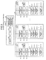
- FIG. 4 is a process flowchart illustrating a determination operation for executing a cell balance according to the embodiment.
- the BMU 36 of the battery unit 23-1 obtains, via the communication controller 74 and the host communication bus (CAN) connected to the gateway device 24 or the BMU 36 of the battery units 23-2 to 23-M, the opened or closed state of the contactors 35 of the other battery units 23-2 to 23-M connected to the host communication bus (S11).
- CAN host communication bus
- the BMU 36 of the battery unit 23-1 determines whether the contactors 35 of all the battery units 23-1 to 23-M is opened (S12).
- the BMU 36 of the battery unit 23-1 obtains the maximum cell voltage (maximum cell module voltage) and the minimum cell voltage (minimum cell module voltage) from the cell modules 31-1 to 31-24 configuring the other battery units 23-2 to 23-M connected to the host communication bus (S13).
- the BMU 36 of the battery unit 23-1 then calculates the difference between the maximum cell voltage and the minimum cell voltage (differential voltage) of each of the battery units 23-1 to 23-M (S14).
- the BMU 36 of the battery unit 23-1 determines whether the difference between the maximum cell voltage and the minimum cell voltage is equal to or less than a certain value, in any of the battery units 23-1 to 23-M (S15).
- the BMU 36 of the battery unit 23-1 functions as a minimum value determination unit and a controller, and from the battery units in which the difference between the maximum cell voltage and the minimum cell voltage is equal to or less than a certain value in the battery unit, sets the most minimum cell voltage as a cell balance target voltage (S16). The process then proceeds to S17.
- the BMU 36 of the battery unit 23-1 sets the minimum cell voltage of the battery unit 23-1 as a cell balance target voltage (S18).
- the above explanation is a cell balance process performed only during normal operation and when the difference between the maximum cell voltage and the minimum cell voltage is above a certain value due to maintenance and the like, it is possible to set a cell balance target voltage accordingly by giving a clear instruction to the BMU 36 of the battery unit 23-1.
- the BMU 36 of the battery unit 23-1 then executes the cell balance process according to the cell balance target voltage and finishes the process (S17).
- the BMU 36 of the battery unit 23-1 obtains the main circuit voltage of the other battery units 23-2 to 23-M connected to the host communication bus (S20).
- the BMU 36 of the battery unit 23-1 compares the main circuit voltage of the other battery units in which the contactor 35 is closed and the main circuit voltage of the battery unit 23-1, and determines whether the main circuit voltage of the battery unit 23-1 (local battery unit) is the same or higher (S21).
- the BMU 36 of the battery unit 23-1 finishes the process without performing the cell balance process.
- the present embodiment it is possible to prevent the cell balance process being performed by referring to the voltage of a battery cell in an abnormal state. Even if an abnormality occurs in a battery cell (or cell module) configuring the storage battery device 11, it is possible to prevent the influence and to enhance the utilization of the storage battery system 3.
- a computer program executed in the storage battery management device is provided by being recorded in a computer-readable memory medium such as a compact disc read-only memory (CD-ROM), a flexible disk (FD), a compact-disc recordable (CD-R), a digital versatile disc (DVD) in a file of an installable form or an executable form.
- a computer-readable memory medium such as a compact disc read-only memory (CD-ROM), a flexible disk (FD), a compact-disc recordable (CD-R), a digital versatile disc (DVD) in a file of an installable form or an executable form.
- the computer program executed in the storage battery management device according to the present embodiment may be stored on a computer connected to a network such as the Internet, and provided by causing a user to download it via the network.
- the computer program executed in the storage battery management device according to the present embodiment may also be provided or distributed via a network such as the Internet.
- the computer program of the storage battery management device can also be provided by being incorporated in a read-only memory (ROM) or the like in advance.
- ROM read-only memory
- the computer program executed in the storage battery management device is composed of a modular configuration including respective units (minimum value determination unit and controller) described above, and as actual hardware, the CPU (processor) reads out the computer program from the recording medium described above and executes the computer program, thereby loading the respective units on the main memory device, and the minimum value determination unit and the controller are generated on the main memory device.
Landscapes
- Engineering & Computer Science (AREA)
- Power Engineering (AREA)
- Physics & Mathematics (AREA)
- General Physics & Mathematics (AREA)
- Manufacturing & Machinery (AREA)
- Chemical & Material Sciences (AREA)
- Chemical Kinetics & Catalysis (AREA)
- Electrochemistry (AREA)
- General Chemical & Material Sciences (AREA)
- Charge And Discharge Circuits For Batteries Or The Like (AREA)
- Secondary Cells (AREA)
Abstract
Description
- An embodiment of the present invention relates to a storage battery management device, a method, and a computer program.
- In recent years, safe and clean natural energy such as solar power generation and wind power generation has been introduced. However, the output of natural energy is not stable, and the mass introduction may negatively affect the voltage and frequency of power systems. If the supply of natural energy largely exceeds the power demand, the natural energy power generation systems need to be stopped, resulting in reduced utilization of power generation facilities.
- To solve such problems, a large-scale storage battery system using secondary batteries is added to the power generation systems, and is expected to prevent output fluctuations of the natural energy by charging/discharging power to and from the storage batteries, and to store surplus power in the storage batteries.
-
- Patent Literature 1: Japanese Patent Application Laid-open No.
2013-179739 - Patent Literature 2:
Japanese Patent Application Laid-open No. 2009-124933 - Patent Literature 3: Japanese Patent Application Laid-open No.
2009-212020 - In large-scale storage battery systems such as a storage battery system for power systems, the required storage battery capacity is obtained by configuring a storage battery device including a plurality of battery modules arranged in parallel, in which a plurality of battery cells are connected in series.
- To adjust the cell balance of such a storage battery device, the voltage of a single battery cell having the lowest voltage in the storage battery device is used as a target voltage to adjust the voltage of other single battery cells.
- However, for example, if abnormally low voltage occurs in a single battery cell forming a storage battery device, the voltage of all the cells can possibly be adjusted to the voltage of the abnormal cell.
- The present invention has been made to solve the problem, and an object of the present invention is to provide a storage battery management device, a method, and a computer program capable of preventing an influence even if an abnormality occurs in a battery cell (or cell module) forming a battery unit, and providing enhanced utilization.
- A storage battery management device according to an embodiment manages a plurality of battery units in a storage battery system including the battery units having a plurality of battery cells and a power adjustment device connected to the battery units via respective contactors and connected to a main circuit.
- A minimum value determination unit, from the battery units in which a difference between a maximum cell voltage and a minimum cell voltage of the battery cells forming each of the battery units is equal to or less than a certain value, determines a minimum value of the minimum cell voltage.
- A controller controls a cell balance process of the battery unit managed by itself, by using the minimum value of the minimum cell voltage determined by the minimum value determination unit as a cell balance target voltage.
-
-
FIG. 1 is a schematic configuration diagram of a natural energy power generation system including a plurality of storage battery systems. -
FIG. 2 is a schematic configuration block diagram of a storage battery system according to an embodiment. -
FIG. 3 is a detailed configuration diagram for explaining a cell module, a CMU, and a BMU. -
FIG. 4 is a process flowchart illustrating a determination operation for executing a cell balance according to the embodiment. - An embodiment will now be described with reference to the accompanying drawings.
-
FIG. 1 is a schematic configuration diagram of a natural energy power generation system including a plurality of storage battery systems. - A natural energy
power generation system 100 includes: a natural energy power generation unit 1 that functions as a power system, uses natural energy (renewable energy) such as solar light, hydraulic power, wind power, biomass, and geothermal, and is capable of outputting the energy as system power; apower meter 2 that measures the power generated by the natural energy power generation unit 1; a plurality ofstorage battery systems 3 that charge surplus power and discharge deficient power of the natural energy power generation unit 1 based on the measurement results by an anemometer and thepower meter 2, and output the resulting power including superimposition of the charged or discharged power on the power generated by the natural energy power generation unit 1; atransformer 4 that converts the voltage of the power (including when the power output from thestorage battery systems 3 includes superimposition) output from the natural energy power generation unit 1; astorage battery controller 5 that locally controls a storage battery system 3n; and a host controllingdevice 6 that remotely controls thestorage battery controller 5. -
FIG. 2 is a schematic configuration block diagram of a storage battery system according to the embodiment. - The
storage battery system 3, when roughly classified, includes astorage battery device 11 that stores power therein and a power conditioning system (PCS) 12 that converts direct current power supplied from thestorage battery device 11 to alternating current power having a desired power quality and supplies it to a load. - The
storage battery device 11, when roughly classified, includes a plurality of battery boards 21-1 to 21-N (N being a natural number) and abattery terminal board 22 to which the battery boards 21-1 to 21-N are connected. - Each of the battery boards 21-1 to 21-N includes a plurality of battery units 23-1 to 23-M (M being a natural number) connected in parallel with each other, a
gateway device 24, and a direct currentpower source device 25 that supplies direct current power to operate a battery management unit (BMU) and a cell monitoring unit (CMU), which will be described later. - A configuration of a battery unit will now be described.
- Each of the battery units 23-1 to 23-M is connected to output power lines (bus) LHO and LLO via a high potential side power supply line LH and a low potential side power supply line LL, and supplies power to the PCS 12, which is a main circuit.
- Because the battery units 23-1 to 23-M have the same configuration, the battery unit 23-1 is explained as an example.
- The battery unit 23-1, when roughly classified, includes a plurality (24 in
FIG. 1 ) of cell modules 31-1 to 31-24, a plurality (24 inFIG. 1 ) of CMUs 32-1 to 32-24 provided respectively to the cell modules 31-1 to 31-24, aservice disconnect 33 provided between the cell module 31-12 and the cell module 31-13, acurrent sensor 34, and acontactor 35. The cell modules 31-1 to 31-24, the service disconnect 33, thecurrent sensor 34, and thecontactor 35 are connected in series. - The cell modules 31-1 to 31-24 configure a battery pack by connecting a plurality of battery cells in series and in parallel. The cell modules 31-1 to 31-24 connected in series configure a battery pack group.
- The battery unit 23-1 also includes a
BMU 36. The communication line of each of the CMUs 32-1 to 32-24 and the output line of thecurrent sensor 34 are connected to theBMU 36. - The
BMU 36 controls the entire battery unit 23-1 under the control of thegateway device 24, and controls the opening and closing of thecontactor 35 based on the communication results (voltage data and temperature data, which will be described later) with each of the CMUs 32-1 to 32-24 and the detection result of thecurrent sensor 34. - The configuration of the
battery terminal board 22 will now be described. - The
battery terminal board 22 includes a plurality of board breakers 41-1 to 41-N provided corresponding to the battery boards 21-1 to 21-N and amaster device 42 configured as a microcomputer that controls the entirestorage battery device 11. - The
master device 42 is connected to the PCS 12 through acontrol power line 51 supplied via an uninterruptible power system (UPS) 12A of the PCS 12 and acontrol communication line 52 configured as an Ethernet (registered trademark) and with which theBMU 36 and the PCS 12 directly exchange control data by functioning as a communication bus. Themaster device 42 is also connected to acommunication line 53 electrically connected to thecontrol communication line 52 and with which data is exchanged directly with anotherBMU 36 by functioning as a communication bus. - Detailed configurations of the cell modules 31-1 to 31-24, the CMUs 32-1 to 32-24, and the
BMU 36 will now be described. -
FIG. 3 is a detailed configuration diagram for explaining a cell module, a CMU, and a BMU. - Each of the cell modules 31-1 to 31-24 includes a plurality (10 in
FIG. 2 ) of battery cells 61-1 to 61-10 connected in series. - Each of the CMUs 32-1 to 32-24 includes an analog front end IC (AFE-IC) 62 used for measuring the voltage of the battery cells configuring the corresponding cell modules 31-1 to 31-24 and the temperature of a certain location, a microprocessor unit (MPU) 63 that controls the entire corresponding CMUs 32-1 to 32-24, a
communication controller 64 in compliance with the Controller Area Network (CAN) standard so as to perform the CAN communication with theBMU 36, and a memory 65 that stores therein voltage data corresponding to the voltage of each cell as well as temperature data. - In the following explanation, the configuration that combines each of the cell modules 31-1 to 31-24 and the corresponding CMUs 32-1 to 32-24 is referred to as battery modules 37-1 to 37-24. For example, a configuration that combines the cell module 31-1 and the corresponding CMU 32-1 is referred to as a battery module 37-1.
- The BMU 36 includes an MPU 71 that controls the
entire BMU 36, a communication controller 72 in compliance with the CAN standard so as to perform the CAN communication with the CMUs 32-1 to 32-24, a memory 73 that stores therein voltage data and temperature data transmitted from the CMUs 32-1 to 32-24, and acommunication controller 74 in compliance with the CAN standard so as to perform the CAN communication with thegateway device 24 or theBMU 36 of the battery units 23-2 to 23-M. - The
storage battery controller 5 detects the power generated by the natural energy power generation unit 1, and to ease the influence of the generated power on the power system, suppresses the output fluctuation of the generated power by using thestorage battery device 11. The fluctuation suppression amount relative to thestorage battery device 11 is calculated by thestorage battery controller 5 or thehost controlling device 6, and applied to thePCS 12 corresponding to thestorage battery device 11 as a charge/discharge command. - An operation of executing the cell balance in the
storage battery device 11 will now be described. - In the following example, the
BMU 36 of the battery unit 23-1 actually performs a determination operation for executing the cell balance, when the determination operation for executing the cell balance of thestorage battery device 11 is performed by the battery unit 23-1. -
FIG. 4 is a process flowchart illustrating a determination operation for executing a cell balance according to the embodiment. - The
BMU 36 of the battery unit 23-1 obtains, via thecommunication controller 74 and the host communication bus (CAN) connected to thegateway device 24 or theBMU 36 of the battery units 23-2 to 23-M, the opened or closed state of thecontactors 35 of the other battery units 23-2 to 23-M connected to the host communication bus (S11). - The
BMU 36 of the battery unit 23-1 then determines whether thecontactors 35 of all the battery units 23-1 to 23-M is opened (S12). - At S12, if the
contactors 35 of all the battery units 23-1 to 23-M are opened (Yes at S12), theBMU 36 of the battery unit 23-1 obtains the maximum cell voltage (maximum cell module voltage) and the minimum cell voltage (minimum cell module voltage) from the cell modules 31-1 to 31-24 configuring the other battery units 23-2 to 23-M connected to the host communication bus (S13). - The
BMU 36 of the battery unit 23-1 then calculates the difference between the maximum cell voltage and the minimum cell voltage (differential voltage) of each of the battery units 23-1 to 23-M (S14). - The
BMU 36 of the battery unit 23-1 then determines whether the difference between the maximum cell voltage and the minimum cell voltage is equal to or less than a certain value, in any of the battery units 23-1 to 23-M (S15). - At S15, if the difference between the maximum cell voltage and the minimum cell voltage is equal to or less than a certain value in any of the other battery units 23-2 to 23-M (Yes at S15), the
BMU 36 of the battery unit 23-1 functions as a minimum value determination unit and a controller, and from the battery units in which the difference between the maximum cell voltage and the minimum cell voltage is equal to or less than a certain value in the battery unit, sets the most minimum cell voltage as a cell balance target voltage (S16). The process then proceeds to S17. - At S15, if the difference between the maximum cell voltage and the minimum cell voltage is not equal to or less than a certain value in any of the battery units 23-2 to 23-M (No at S15), in other words, if the difference between the maximum cell voltage and the minimum cell voltage is above a certain value, the
BMU 36 of the battery unit 23-1 sets the minimum cell voltage of the battery unit 23-1 as a cell balance target voltage (S18). - This is because, if the difference between the maximum cell voltage and the minimum cell voltage is above a certain value, some battery unit may have a failure of some kind. Thus, this is to avoid setting a cell balance target voltage accordingly.
- The above explanation is a cell balance process performed only during normal operation and when the difference between the maximum cell voltage and the minimum cell voltage is above a certain value due to maintenance and the like, it is possible to set a cell balance target voltage accordingly by giving a clear instruction to the
BMU 36 of the battery unit 23-1. - The
BMU 36 of the battery unit 23-1 then executes the cell balance process according to the cell balance target voltage and finishes the process (S17). - At S12, if the
contactors 35 of not all the battery units 23-1 to 23-M are opened (No at S12), in other words, if thecontactor 35 of a part of the battery units is closed, theBMU 36 of the battery unit 23-1 obtains the main circuit voltage of the other battery units 23-2 to 23-M connected to the host communication bus (S20). - The
BMU 36 of the battery unit 23-1 then compares the main circuit voltage of the other battery units in which thecontactor 35 is closed and the main circuit voltage of the battery unit 23-1, and determines whether the main circuit voltage of the battery unit 23-1 (local battery unit) is the same or higher (S21). - At S21, if the main circuit voltage of the other battery units in which the
contactor 35 is closed is the same or higher than the main circuit voltage of the battery unit 23-1 (Yes at S21), the process proceeds to S13 again to continue the same process. - If the main circuit voltage of the other battery units in which the
contactor 35 is closed is lower than the main circuit voltage of the battery unit 23-1 (No at S21), theBMU 36 of the battery unit 23-1 finishes the process without performing the cell balance process. - This is because, if the voltage of the battery unit 23-1 diverges excessively from that of the other battery units 23-2 to 23-M, the
contactor 35 may become unclosable. This is to prevent such things. - As described above, according to the present embodiment, it is possible to prevent the cell balance process being performed by referring to the voltage of a battery cell in an abnormal state. Even if an abnormality occurs in a battery cell (or cell module) configuring the
storage battery device 11, it is possible to prevent the influence and to enhance the utilization of thestorage battery system 3. - A computer program executed in the storage battery management device according to the present embodiment is provided by being recorded in a computer-readable memory medium such as a compact disc read-only memory (CD-ROM), a flexible disk (FD), a compact-disc recordable (CD-R), a digital versatile disc (DVD) in a file of an installable form or an executable form.
- The computer program executed in the storage battery management device according to the present embodiment may be stored on a computer connected to a network such as the Internet, and provided by causing a user to download it via the network. The computer program executed in the storage battery management device according to the present embodiment may also be provided or distributed via a network such as the Internet.
- The computer program of the storage battery management device according to the present embodiment can also be provided by being incorporated in a read-only memory (ROM) or the like in advance.
- The computer program executed in the storage battery management device according to the present embodiment is composed of a modular configuration including respective units (minimum value determination unit and controller) described above, and as actual hardware, the CPU (processor) reads out the computer program from the recording medium described above and executes the computer program, thereby loading the respective units on the main memory device, and the minimum value determination unit and the controller are generated on the main memory device.
- Some exemplary embodiments of the present invention have been described but such embodiments are not meant to limit the scope of the invention. These new embodiments may be carried out in various other modes, and various omissions, replacements, and modifications are possible without departing from the spirit of the invention. These embodiments and the modifications fall within the scope and spirit of the invention, and also within the invention described in the accompanying claims and their equivalents.
Claims (5)
- A storage battery management device that manages a plurality of battery units in a storage battery system including the battery units having a plurality of battery cells and a power adjustment device connected to the battery units via respective contactors and connected to a main circuit, the storage battery management device comprising:a minimum value determination unit that, from the battery units in which a difference between a maximum cell voltage and a minimum cell voltage of the battery cells forming each of the battery units is equal to or less than a certain value, determines a minimum value of the minimum cell voltage; anda controller that controls a cell balance process of the battery unit managed by itself, by using the minimum value of the minimum cell voltage determined by the minimum value determination unit as a cell balance target voltage.
- The storage battery management device according to claim 1, wherein if all the differences between the maximum cell voltage and the minimum cell voltage of the battery cells forming the battery units connected to the power adjustment device via a communication bus are above a certain value, the controller controls the cell balance process by using the minimum cell voltage of the battery cells forming the battery unit managed by itself as the cell balance target voltage.
- The storage battery management device according to claim 1 or 2, wherein
a connection with the power adjustment device is provided via the communication bus, and
the maximum cell voltage and the minimum cell voltage are acquired, via the communication bus, from the other battery units connected to the communication bus. - A method executed by a storage battery management device that manages a plurality of battery units in a storage battery system including the battery units having a plurality of battery cells and a power adjustment device connected to the battery units via respective contactors and connected to a main circuit, the method comprising:determining, from the battery units in which a difference between a maximum cell voltage and a minimum cell voltage of the battery cells forming each of the battery units is equal to or less than a certain value, a minimum value of the minimum cell voltage; andcontrolling a cell balance process of the battery unit managed by itself, by using the determined minimum value of the minimum cell voltage as a cell balance target voltage.
- A computer program for controlling a storage battery management device that manages a plurality of battery units, in a storage battery system including the battery units having a plurality of battery cells and a power adjustment device connected to the battery units via respective contactors and connected to a main circuit, by a computer, the computer program causing the computer to function as:determining means that, from the battery units in which a difference between a maximum cell voltage and a minimum cell voltage of the battery cells forming each of the battery units is equal to or less than a certain value, determines a minimum value of the minimum cell voltage; andcontrolling means that controls a cell balance process of the battery unit managed by itself by using the determined minimum value of the minimum cell voltage as a cell balance target voltage.
Applications Claiming Priority (1)
| Application Number | Priority Date | Filing Date | Title |
|---|---|---|---|
| PCT/JP2015/057765 WO2016147306A1 (en) | 2015-03-16 | 2015-03-16 | Storage battery management apparatus, method, and program |
Publications (3)
| Publication Number | Publication Date |
|---|---|
| EP3093947A1 true EP3093947A1 (en) | 2016-11-16 |
| EP3093947A4 EP3093947A4 (en) | 2017-03-01 |
| EP3093947B1 EP3093947B1 (en) | 2018-06-06 |
Family
ID=56919822
Family Applications (1)
| Application Number | Title | Priority Date | Filing Date |
|---|---|---|---|
| EP15753600.4A Active EP3093947B1 (en) | 2015-03-16 | 2015-03-16 | Storage battery management apparatus, method, and program |
Country Status (7)
| Country | Link |
|---|---|
| US (1) | US9859721B2 (en) |
| EP (1) | EP3093947B1 (en) |
| JP (1) | JP6174154B2 (en) |
| KR (1) | KR101838362B1 (en) |
| CN (1) | CN107431363B (en) |
| ES (1) | ES2685856T3 (en) |
| WO (1) | WO2016147306A1 (en) |
Cited By (1)
| Publication number | Priority date | Publication date | Assignee | Title |
|---|---|---|---|---|
| FR3148176A1 (en) | 2023-04-25 | 2024-11-01 | Psa Automobiles Sa | METHOD FOR BALANCING AN ENERGY STORAGE SYSTEM |
Families Citing this family (10)
| Publication number | Priority date | Publication date | Assignee | Title |
|---|---|---|---|---|
| WO2020086973A1 (en) | 2018-10-26 | 2020-04-30 | Cummins Inc. | BATTERY CHARGING AND DISCHARGING OF MULTIPLE PACKS AT DIFFERENT STATES OF CHARGE (SOCs) |
| KR102842049B1 (en) | 2019-06-28 | 2025-08-04 | 주식회사 엘지에너지솔루션 | Apparatus and method for detecting poor battery cell |
| CN111509317B (en) * | 2020-03-01 | 2022-09-16 | 青岛能蜂电气有限公司 | Energy storage management method and system for storage battery and electronic equipment |
| KR20220057368A (en) * | 2020-10-29 | 2022-05-09 | 주식회사 엘지에너지솔루션 | Apparatus and method for managing battery, battery managing system |
| KR20220100332A (en) * | 2021-01-08 | 2022-07-15 | 주식회사 엘지에너지솔루션 | Battery apparatus and method of supplying voltage |
| US12512681B2 (en) * | 2021-02-15 | 2025-12-30 | Tdk Corporation | Power management device and power feeding system |
| CN113472037B (en) * | 2021-06-24 | 2024-07-19 | 珠海中力新能源科技有限公司 | A battery pack balancing method, a battery pack balancing device and a battery management system |
| CN117214726B (en) * | 2023-11-02 | 2024-01-26 | 江苏天合储能有限公司 | State detection method and device, electronic equipment and computer readable storage medium |
| WO2025249969A1 (en) * | 2024-05-31 | 2025-12-04 | 삼성전자 주식회사 | Electronic device and method for charging battery cells in electronic device |
| SE2450794A1 (en) * | 2024-07-10 | 2026-01-11 | Sem Ab | A battery system and a method for controlling a battery system |
Family Cites Families (14)
| Publication number | Priority date | Publication date | Assignee | Title |
|---|---|---|---|---|
| JP2003289629A (en) * | 2002-03-27 | 2003-10-10 | Mitsubishi Heavy Ind Ltd | Voltage equalizer in capacitor and power storage system equipped with the device |
| TWI359548B (en) | 2007-11-16 | 2012-03-01 | Advance Smart Ind Ltd | Alarm protected addapatus for lithium-ion battery |
| CN101471577B (en) * | 2007-12-29 | 2011-06-15 | 比亚迪股份有限公司 | Voltage balance circuit for double-burl chargeable battery |
| JP5184921B2 (en) | 2008-03-06 | 2013-04-17 | 株式会社東芝 | Power storage device |
| JP5529402B2 (en) * | 2008-08-13 | 2014-06-25 | 三菱重工業株式会社 | Power storage system |
| US8541979B2 (en) * | 2010-06-22 | 2013-09-24 | A123 Systems, Inc. | System and method for balancing voltage of individual battery cells within a battery pack |
| US20110309796A1 (en) * | 2010-06-22 | 2011-12-22 | A123 Systems, Inc. | System and Method for Managing Charge Within a Battery Pack |
| JP2012039821A (en) * | 2010-08-10 | 2012-02-23 | Toshiba Corp | Power fluctuation relaxing device of power generating system and power fluctuation relaxing method |
| US20130187466A1 (en) * | 2010-10-15 | 2013-07-25 | Sanyo Electric Co., Ltd. | Power management system |
| WO2012114479A1 (en) * | 2011-02-23 | 2012-08-30 | 株式会社日立製作所 | Power storage system provided with batteries |
| JP2013051759A (en) * | 2011-08-30 | 2013-03-14 | Toshiba Corp | Battery pack monitoring device, secondary battery device, and vehicle |
| WO2013061759A1 (en) * | 2011-10-27 | 2013-05-02 | 三洋電機株式会社 | Battery unit, electric vehicle, mobile object, power supply apparatus, and battery control apparatus |
| JP5748689B2 (en) | 2012-02-28 | 2015-07-15 | 三菱重工業株式会社 | Battery system |
| JP5583194B2 (en) * | 2012-11-21 | 2014-09-03 | 三菱重工業株式会社 | Battery system, battery management apparatus and battery management method |
-
2015
- 2015-03-16 CN CN201580000360.4A patent/CN107431363B/en active Active
- 2015-03-16 US US14/771,962 patent/US9859721B2/en active Active
- 2015-03-16 KR KR1020157023757A patent/KR101838362B1/en active Active
- 2015-03-16 WO PCT/JP2015/057765 patent/WO2016147306A1/en not_active Ceased
- 2015-03-16 ES ES15753600.4T patent/ES2685856T3/en active Active
- 2015-03-16 EP EP15753600.4A patent/EP3093947B1/en active Active
- 2015-03-16 JP JP2015535910A patent/JP6174154B2/en active Active
Cited By (1)
| Publication number | Priority date | Publication date | Assignee | Title |
|---|---|---|---|---|
| FR3148176A1 (en) | 2023-04-25 | 2024-11-01 | Psa Automobiles Sa | METHOD FOR BALANCING AN ENERGY STORAGE SYSTEM |
Also Published As
| Publication number | Publication date |
|---|---|
| JP6174154B2 (en) | 2017-08-02 |
| KR101838362B1 (en) | 2018-03-13 |
| CN107431363A (en) | 2017-12-01 |
| JPWO2016147306A1 (en) | 2017-04-27 |
| EP3093947A4 (en) | 2017-03-01 |
| EP3093947B1 (en) | 2018-06-06 |
| ES2685856T3 (en) | 2018-10-11 |
| WO2016147306A1 (en) | 2016-09-22 |
| CN107431363B (en) | 2020-06-26 |
| US20160276846A1 (en) | 2016-09-22 |
| KR20160130939A (en) | 2016-11-15 |
| US9859721B2 (en) | 2018-01-02 |
Similar Documents
| Publication | Publication Date | Title |
|---|---|---|
| EP3093947B1 (en) | Storage battery management apparatus, method, and program | |
| JP6571268B2 (en) | Battery monitoring apparatus and method | |
| EP3086133A1 (en) | Storage battery management device, method and program | |
| US20150194707A1 (en) | Battery pack, energy storage system including the battery pack, and method of operating the battery pack | |
| EP3514557A1 (en) | Electric storage capacity estimation device, method and program | |
| WO2015040724A1 (en) | Storage battery system | |
| JPWO2017154115A1 (en) | Storage battery device, storage battery system, method and control program | |
| EP3273567B1 (en) | Storage battery management device, method, and program | |
| JP2017505098A5 (en) | ||
| JP6622380B2 (en) | Storage battery device and method | |
| KR102793991B1 (en) | Energy storage system connected to photovolatic system and controlling method thereof | |
| KR102061308B1 (en) | Control power supplying apparatus and method for battery management and energy stock system using the same | |
| JPWO2015040722A1 (en) | Battery system | |
| JP6334423B2 (en) | Storage battery device, storage battery system, method and program | |
| WO2016147326A1 (en) | Storage-battery management device, method, and program | |
| WO2017042973A1 (en) | Storage battery system, method, and program | |
| WO2016147322A1 (en) | Storage cell management device, method, and program | |
| JP7293145B2 (en) | MONITORING CONTROL DEVICE, STORAGE BATTERY SYSTEM AND METHOD | |
| JP6585705B2 (en) | Charge / discharge system | |
| HK1229890A1 (en) | Method and system for managing a plurality of energy storage assemblies | |
| HK1229890B (en) | Method and system for managing a plurality of energy storage assemblies | |
| HK1252944B (en) | Power supply device |
Legal Events
| Date | Code | Title | Description |
|---|---|---|---|
| PUAI | Public reference made under article 153(3) epc to a published international application that has entered the european phase |
Free format text: ORIGINAL CODE: 0009012 |
|
| 17P | Request for examination filed |
Effective date: 20150901 |
|
| AK | Designated contracting states |
Kind code of ref document: A1 Designated state(s): AL AT BE BG CH CY CZ DE DK EE ES FI FR GB GR HR HU IE IS IT LI LT LU LV MC MK MT NL NO PL PT RO RS SE SI SK SM TR |
|
| AX | Request for extension of the european patent |
Extension state: BA ME |
|
| A4 | Supplementary search report drawn up and despatched |
Effective date: 20170131 |
|
| RIC1 | Information provided on ipc code assigned before grant |
Ipc: H02J 7/02 20160101AFI20170125BHEP Ipc: H02J 7/35 20060101ALI20170125BHEP Ipc: H02J 7/00 20060101ALI20170125BHEP Ipc: H01M 10/42 20060101ALI20170125BHEP Ipc: H02J 3/32 20060101ALI20170125BHEP |
|
| GRAP | Despatch of communication of intention to grant a patent |
Free format text: ORIGINAL CODE: EPIDOSNIGR1 |
|
| STAA | Information on the status of an ep patent application or granted ep patent |
Free format text: STATUS: GRANT OF PATENT IS INTENDED |
|
| RIC1 | Information provided on ipc code assigned before grant |
Ipc: H01M 10/42 20060101ALI20171207BHEP Ipc: H02J 3/32 20060101ALI20171207BHEP Ipc: H02J 7/35 20060101ALI20171207BHEP Ipc: H02J 7/02 20160101AFI20171207BHEP Ipc: H02J 7/00 20060101ALI20171207BHEP |
|
| DAV | Request for validation of the european patent (deleted) | ||
| DAX | Request for extension of the european patent (deleted) | ||
| INTG | Intention to grant announced |
Effective date: 20180102 |
|
| GRAS | Grant fee paid |
Free format text: ORIGINAL CODE: EPIDOSNIGR3 |
|
| GRAA | (expected) grant |
Free format text: ORIGINAL CODE: 0009210 |
|
| STAA | Information on the status of an ep patent application or granted ep patent |
Free format text: STATUS: THE PATENT HAS BEEN GRANTED |
|
| AK | Designated contracting states |
Kind code of ref document: B1 Designated state(s): AL AT BE BG CH CY CZ DE DK EE ES FI FR GB GR HR HU IE IS IT LI LT LU LV MC MK MT NL NO PL PT RO RS SE SI SK SM TR |
|
| REG | Reference to a national code |
Ref country code: GB Ref legal event code: FG4D |
|
| REG | Reference to a national code |
Ref country code: CH Ref legal event code: EP Ref country code: AT Ref legal event code: REF Ref document number: 1007110 Country of ref document: AT Kind code of ref document: T Effective date: 20180615 |
|
| REG | Reference to a national code |
Ref country code: IE Ref legal event code: FG4D |
|
| REG | Reference to a national code |
Ref country code: DE Ref legal event code: R096 Ref document number: 602015012035 Country of ref document: DE |
|
| REG | Reference to a national code |
Ref country code: CH Ref legal event code: NV Representative=s name: WEINMANN ZIMMERLI, CH |
|
| REG | Reference to a national code |
Ref country code: NL Ref legal event code: MP Effective date: 20180606 |
|
| REG | Reference to a national code |
Ref country code: ES Ref legal event code: FG2A Ref document number: 2685856 Country of ref document: ES Kind code of ref document: T3 Effective date: 20181011 |
|
| REG | Reference to a national code |
Ref country code: LT Ref legal event code: MG4D |
|
| PG25 | Lapsed in a contracting state [announced via postgrant information from national office to epo] |
Ref country code: BG Free format text: LAPSE BECAUSE OF FAILURE TO SUBMIT A TRANSLATION OF THE DESCRIPTION OR TO PAY THE FEE WITHIN THE PRESCRIBED TIME-LIMIT Effective date: 20180906 Ref country code: FI Free format text: LAPSE BECAUSE OF FAILURE TO SUBMIT A TRANSLATION OF THE DESCRIPTION OR TO PAY THE FEE WITHIN THE PRESCRIBED TIME-LIMIT Effective date: 20180606 Ref country code: LT Free format text: LAPSE BECAUSE OF FAILURE TO SUBMIT A TRANSLATION OF THE DESCRIPTION OR TO PAY THE FEE WITHIN THE PRESCRIBED TIME-LIMIT Effective date: 20180606 Ref country code: SE Free format text: LAPSE BECAUSE OF FAILURE TO SUBMIT A TRANSLATION OF THE DESCRIPTION OR TO PAY THE FEE WITHIN THE PRESCRIBED TIME-LIMIT Effective date: 20180606 Ref country code: NO Free format text: LAPSE BECAUSE OF FAILURE TO SUBMIT A TRANSLATION OF THE DESCRIPTION OR TO PAY THE FEE WITHIN THE PRESCRIBED TIME-LIMIT Effective date: 20180906 Ref country code: CY Free format text: LAPSE BECAUSE OF FAILURE TO SUBMIT A TRANSLATION OF THE DESCRIPTION OR TO PAY THE FEE WITHIN THE PRESCRIBED TIME-LIMIT Effective date: 20180606 |
|
| PG25 | Lapsed in a contracting state [announced via postgrant information from national office to epo] |
Ref country code: RS Free format text: LAPSE BECAUSE OF FAILURE TO SUBMIT A TRANSLATION OF THE DESCRIPTION OR TO PAY THE FEE WITHIN THE PRESCRIBED TIME-LIMIT Effective date: 20180606 Ref country code: HR Free format text: LAPSE BECAUSE OF FAILURE TO SUBMIT A TRANSLATION OF THE DESCRIPTION OR TO PAY THE FEE WITHIN THE PRESCRIBED TIME-LIMIT Effective date: 20180606 Ref country code: GR Free format text: LAPSE BECAUSE OF FAILURE TO SUBMIT A TRANSLATION OF THE DESCRIPTION OR TO PAY THE FEE WITHIN THE PRESCRIBED TIME-LIMIT Effective date: 20180907 Ref country code: LV Free format text: LAPSE BECAUSE OF FAILURE TO SUBMIT A TRANSLATION OF THE DESCRIPTION OR TO PAY THE FEE WITHIN THE PRESCRIBED TIME-LIMIT Effective date: 20180606 |
|
| REG | Reference to a national code |
Ref country code: AT Ref legal event code: MK05 Ref document number: 1007110 Country of ref document: AT Kind code of ref document: T Effective date: 20180606 |
|
| PG25 | Lapsed in a contracting state [announced via postgrant information from national office to epo] |
Ref country code: NL Free format text: LAPSE BECAUSE OF FAILURE TO SUBMIT A TRANSLATION OF THE DESCRIPTION OR TO PAY THE FEE WITHIN THE PRESCRIBED TIME-LIMIT Effective date: 20180606 |
|
| PG25 | Lapsed in a contracting state [announced via postgrant information from national office to epo] |
Ref country code: PL Free format text: LAPSE BECAUSE OF FAILURE TO SUBMIT A TRANSLATION OF THE DESCRIPTION OR TO PAY THE FEE WITHIN THE PRESCRIBED TIME-LIMIT Effective date: 20180606 Ref country code: EE Free format text: LAPSE BECAUSE OF FAILURE TO SUBMIT A TRANSLATION OF THE DESCRIPTION OR TO PAY THE FEE WITHIN THE PRESCRIBED TIME-LIMIT Effective date: 20180606 Ref country code: IS Free format text: LAPSE BECAUSE OF FAILURE TO SUBMIT A TRANSLATION OF THE DESCRIPTION OR TO PAY THE FEE WITHIN THE PRESCRIBED TIME-LIMIT Effective date: 20181006 Ref country code: AT Free format text: LAPSE BECAUSE OF FAILURE TO SUBMIT A TRANSLATION OF THE DESCRIPTION OR TO PAY THE FEE WITHIN THE PRESCRIBED TIME-LIMIT Effective date: 20180606 Ref country code: CZ Free format text: LAPSE BECAUSE OF FAILURE TO SUBMIT A TRANSLATION OF THE DESCRIPTION OR TO PAY THE FEE WITHIN THE PRESCRIBED TIME-LIMIT Effective date: 20180606 Ref country code: RO Free format text: LAPSE BECAUSE OF FAILURE TO SUBMIT A TRANSLATION OF THE DESCRIPTION OR TO PAY THE FEE WITHIN THE PRESCRIBED TIME-LIMIT Effective date: 20180606 Ref country code: SK Free format text: LAPSE BECAUSE OF FAILURE TO SUBMIT A TRANSLATION OF THE DESCRIPTION OR TO PAY THE FEE WITHIN THE PRESCRIBED TIME-LIMIT Effective date: 20180606 |
|
| PG25 | Lapsed in a contracting state [announced via postgrant information from national office to epo] |
Ref country code: SM Free format text: LAPSE BECAUSE OF FAILURE TO SUBMIT A TRANSLATION OF THE DESCRIPTION OR TO PAY THE FEE WITHIN THE PRESCRIBED TIME-LIMIT Effective date: 20180606 |
|
| REG | Reference to a national code |
Ref country code: DE Ref legal event code: R097 Ref document number: 602015012035 Country of ref document: DE |
|
| PLBE | No opposition filed within time limit |
Free format text: ORIGINAL CODE: 0009261 |
|
| STAA | Information on the status of an ep patent application or granted ep patent |
Free format text: STATUS: NO OPPOSITION FILED WITHIN TIME LIMIT |
|
| 26N | No opposition filed |
Effective date: 20190307 |
|
| PG25 | Lapsed in a contracting state [announced via postgrant information from national office to epo] |
Ref country code: DK Free format text: LAPSE BECAUSE OF FAILURE TO SUBMIT A TRANSLATION OF THE DESCRIPTION OR TO PAY THE FEE WITHIN THE PRESCRIBED TIME-LIMIT Effective date: 20180606 Ref country code: SI Free format text: LAPSE BECAUSE OF FAILURE TO SUBMIT A TRANSLATION OF THE DESCRIPTION OR TO PAY THE FEE WITHIN THE PRESCRIBED TIME-LIMIT Effective date: 20180606 |
|
| PG25 | Lapsed in a contracting state [announced via postgrant information from national office to epo] |
Ref country code: MC Free format text: LAPSE BECAUSE OF FAILURE TO SUBMIT A TRANSLATION OF THE DESCRIPTION OR TO PAY THE FEE WITHIN THE PRESCRIBED TIME-LIMIT Effective date: 20180606 |
|
| PG25 | Lapsed in a contracting state [announced via postgrant information from national office to epo] |
Ref country code: LU Free format text: LAPSE BECAUSE OF NON-PAYMENT OF DUE FEES Effective date: 20190316 Ref country code: AL Free format text: LAPSE BECAUSE OF FAILURE TO SUBMIT A TRANSLATION OF THE DESCRIPTION OR TO PAY THE FEE WITHIN THE PRESCRIBED TIME-LIMIT Effective date: 20180606 |
|
| REG | Reference to a national code |
Ref country code: BE Ref legal event code: MM Effective date: 20190331 |
|
| PG25 | Lapsed in a contracting state [announced via postgrant information from national office to epo] |
Ref country code: IE Free format text: LAPSE BECAUSE OF NON-PAYMENT OF DUE FEES Effective date: 20190316 |
|
| PG25 | Lapsed in a contracting state [announced via postgrant information from national office to epo] |
Ref country code: BE Free format text: LAPSE BECAUSE OF NON-PAYMENT OF DUE FEES Effective date: 20190331 |
|
| PG25 | Lapsed in a contracting state [announced via postgrant information from national office to epo] |
Ref country code: TR Free format text: LAPSE BECAUSE OF FAILURE TO SUBMIT A TRANSLATION OF THE DESCRIPTION OR TO PAY THE FEE WITHIN THE PRESCRIBED TIME-LIMIT Effective date: 20180606 |
|
| PG25 | Lapsed in a contracting state [announced via postgrant information from national office to epo] |
Ref country code: MT Free format text: LAPSE BECAUSE OF NON-PAYMENT OF DUE FEES Effective date: 20190316 Ref country code: PT Free format text: LAPSE BECAUSE OF FAILURE TO SUBMIT A TRANSLATION OF THE DESCRIPTION OR TO PAY THE FEE WITHIN THE PRESCRIBED TIME-LIMIT Effective date: 20181008 |
|
| PG25 | Lapsed in a contracting state [announced via postgrant information from national office to epo] |
Ref country code: HU Free format text: LAPSE BECAUSE OF FAILURE TO SUBMIT A TRANSLATION OF THE DESCRIPTION OR TO PAY THE FEE WITHIN THE PRESCRIBED TIME-LIMIT; INVALID AB INITIO Effective date: 20150316 |
|
| PG25 | Lapsed in a contracting state [announced via postgrant information from national office to epo] |
Ref country code: MK Free format text: LAPSE BECAUSE OF FAILURE TO SUBMIT A TRANSLATION OF THE DESCRIPTION OR TO PAY THE FEE WITHIN THE PRESCRIBED TIME-LIMIT Effective date: 20180606 |
|
| PGFP | Annual fee paid to national office [announced via postgrant information from national office to epo] |
Ref country code: FR Payment date: 20230110 Year of fee payment: 9 |
|
| PGFP | Annual fee paid to national office [announced via postgrant information from national office to epo] |
Ref country code: IT Payment date: 20230213 Year of fee payment: 9 Ref country code: GB Payment date: 20230126 Year of fee payment: 9 |
|
| PGFP | Annual fee paid to national office [announced via postgrant information from national office to epo] |
Ref country code: ES Payment date: 20230407 Year of fee payment: 9 |
|
| GBPC | Gb: european patent ceased through non-payment of renewal fee |
Effective date: 20240316 |
|
| PG25 | Lapsed in a contracting state [announced via postgrant information from national office to epo] |
Ref country code: GB Free format text: LAPSE BECAUSE OF NON-PAYMENT OF DUE FEES Effective date: 20240316 |
|
| PG25 | Lapsed in a contracting state [announced via postgrant information from national office to epo] |
Ref country code: FR Free format text: LAPSE BECAUSE OF NON-PAYMENT OF DUE FEES Effective date: 20240331 |
|
| PG25 | Lapsed in a contracting state [announced via postgrant information from national office to epo] |
Ref country code: GB Free format text: LAPSE BECAUSE OF NON-PAYMENT OF DUE FEES Effective date: 20240316 Ref country code: FR Free format text: LAPSE BECAUSE OF NON-PAYMENT OF DUE FEES Effective date: 20240331 |
|
| PG25 | Lapsed in a contracting state [announced via postgrant information from national office to epo] |
Ref country code: IT Free format text: LAPSE BECAUSE OF NON-PAYMENT OF DUE FEES Effective date: 20240316 |
|
| REG | Reference to a national code |
Ref country code: ES Ref legal event code: FD2A Effective date: 20250430 |
|
| PG25 | Lapsed in a contracting state [announced via postgrant information from national office to epo] |
Ref country code: ES Free format text: LAPSE BECAUSE OF NON-PAYMENT OF DUE FEES Effective date: 20240317 |
|
| PGFP | Annual fee paid to national office [announced via postgrant information from national office to epo] |
Ref country code: CH Payment date: 20250401 Year of fee payment: 11 |
|
| REG | Reference to a national code |
Ref country code: CH Ref legal event code: U11 Free format text: ST27 STATUS EVENT CODE: U-0-0-U10-U11 (AS PROVIDED BY THE NATIONAL OFFICE) Effective date: 20260401 |
|
| PGFP | Annual fee paid to national office [announced via postgrant information from national office to epo] |
Ref country code: DE Payment date: 20260102 Year of fee payment: 12 |