EP3093650B1 - Measuring apparatus, measuring method, and program - Google Patents
Measuring apparatus, measuring method, and program Download PDFInfo
- Publication number
- EP3093650B1 EP3093650B1 EP16167764.6A EP16167764A EP3093650B1 EP 3093650 B1 EP3093650 B1 EP 3093650B1 EP 16167764 A EP16167764 A EP 16167764A EP 3093650 B1 EP3093650 B1 EP 3093650B1
- Authority
- EP
- European Patent Office
- Prior art keywords
- light source
- sample
- diffusion
- fourier transform
- coefficient
- Prior art date
- Legal status (The legal status is an assumption and is not a legal conclusion. Google has not performed a legal analysis and makes no representation as to the accuracy of the status listed.)
- Active
Links
Images



Classifications
-
- G—PHYSICS
- G06—COMPUTING OR CALCULATING; COUNTING
- G06T—IMAGE DATA PROCESSING OR GENERATION, IN GENERAL
- G06T5/00—Image enhancement or restoration
- G06T5/20—Image enhancement or restoration using local operators
-
- G—PHYSICS
- G01—MEASURING; TESTING
- G01N—INVESTIGATING OR ANALYSING MATERIALS BY DETERMINING THEIR CHEMICAL OR PHYSICAL PROPERTIES
- G01N21/00—Investigating or analysing materials by the use of optical means, i.e. using sub-millimetre waves, infrared, visible or ultraviolet light
- G01N21/17—Systems in which incident light is modified in accordance with the properties of the material investigated
- G01N21/55—Specular reflectivity
-
- G—PHYSICS
- G01—MEASURING; TESTING
- G01N—INVESTIGATING OR ANALYSING MATERIALS BY DETERMINING THEIR CHEMICAL OR PHYSICAL PROPERTIES
- G01N21/00—Investigating or analysing materials by the use of optical means, i.e. using sub-millimetre waves, infrared, visible or ultraviolet light
- G01N21/17—Systems in which incident light is modified in accordance with the properties of the material investigated
- G01N21/47—Scattering, i.e. diffuse reflection
- G01N21/4738—Diffuse reflection, e.g. also for testing fluids, fibrous materials
-
- G—PHYSICS
- G01—MEASURING; TESTING
- G01N—INVESTIGATING OR ANALYSING MATERIALS BY DETERMINING THEIR CHEMICAL OR PHYSICAL PROPERTIES
- G01N21/00—Investigating or analysing materials by the use of optical means, i.e. using sub-millimetre waves, infrared, visible or ultraviolet light
- G01N21/17—Systems in which incident light is modified in accordance with the properties of the material investigated
- G01N21/47—Scattering, i.e. diffuse reflection
- G01N21/49—Scattering, i.e. diffuse reflection within a body or fluid
- G01N21/53—Scattering, i.e. diffuse reflection within a body or fluid within a flowing fluid, e.g. smoke
- G01N21/532—Scattering, i.e. diffuse reflection within a body or fluid within a flowing fluid, e.g. smoke with measurement of scattering and transmission
-
- G—PHYSICS
- G01—MEASURING; TESTING
- G01N—INVESTIGATING OR ANALYSING MATERIALS BY DETERMINING THEIR CHEMICAL OR PHYSICAL PROPERTIES
- G01N21/00—Investigating or analysing materials by the use of optical means, i.e. using sub-millimetre waves, infrared, visible or ultraviolet light
- G01N21/84—Systems specially adapted for particular applications
- G01N21/8422—Investigating thin films, e.g. matrix isolation method
-
- G—PHYSICS
- G06—COMPUTING OR CALCULATING; COUNTING
- G06T—IMAGE DATA PROCESSING OR GENERATION, IN GENERAL
- G06T7/00—Image analysis
- G06T7/30—Determination of transform parameters for the alignment of images, i.e. image registration
- G06T7/32—Determination of transform parameters for the alignment of images, i.e. image registration using correlation-based methods
-
- G—PHYSICS
- G06—COMPUTING OR CALCULATING; COUNTING
- G06T—IMAGE DATA PROCESSING OR GENERATION, IN GENERAL
- G06T7/00—Image analysis
- G06T7/30—Determination of transform parameters for the alignment of images, i.e. image registration
- G06T7/37—Determination of transform parameters for the alignment of images, i.e. image registration using transform domain methods
-
- G—PHYSICS
- G01—MEASURING; TESTING
- G01N—INVESTIGATING OR ANALYSING MATERIALS BY DETERMINING THEIR CHEMICAL OR PHYSICAL PROPERTIES
- G01N21/00—Investigating or analysing materials by the use of optical means, i.e. using sub-millimetre waves, infrared, visible or ultraviolet light
- G01N21/84—Systems specially adapted for particular applications
- G01N21/8422—Investigating thin films, e.g. matrix isolation method
- G01N2021/8427—Coatings
-
- G—PHYSICS
- G01—MEASURING; TESTING
- G01N—INVESTIGATING OR ANALYSING MATERIALS BY DETERMINING THEIR CHEMICAL OR PHYSICAL PROPERTIES
- G01N21/00—Investigating or analysing materials by the use of optical means, i.e. using sub-millimetre waves, infrared, visible or ultraviolet light
- G01N21/17—Systems in which incident light is modified in accordance with the properties of the material investigated
- G01N21/55—Specular reflectivity
- G01N21/57—Measuring gloss
-
- G—PHYSICS
- G01—MEASURING; TESTING
- G01N—INVESTIGATING OR ANALYSING MATERIALS BY DETERMINING THEIR CHEMICAL OR PHYSICAL PROPERTIES
- G01N2223/00—Investigating materials by wave or particle radiation
- G01N2223/30—Accessories, mechanical or electrical features
- G01N2223/345—Accessories, mechanical or electrical features mathematical transformations on beams or signals, e.g. Fourier
Definitions
- the present invention relates to, for example, a measuring apparatus for measuring an optical characteristic of a sample.
- such measuring apparatuses include an apparatus that first obtains the diffusion characteristic (e.g., a bidirectional reflectance distribution function (abbreviated as BRDF)).
- This apparatus may function as a general-purpose apparatus that obtains a plurality of additional indices (e.g., the specular gloss, the haze, and the image clarity) on the basis of the diffusion characteristic.
- a sample may be disposed in the pupil, a secondary light source may be provided at the anterior focal point, and an image sensor may be provided at the posterior focal point.
- Japanese Patent Laid-Open No. 2010-276492 discloses an apparatus in which a pinhole serves as a secondary light source and an image of the pinhole is taken by an image sensor. Since the pinhole serves as the secondary light source, the diffusion characteristic with a high angular resolution can be obtained, but this apparatus may suffer from a disadvantage in securing the quantity of light or the luminous sensitivity. Meanwhile, Japanese Patent Laid-Open No. 2008-256454 discloses an apparatus in which an aperture in an aperture plate serves as a secondary light source and an image of the aperture is taken by an image sensor.
- Increasing the angle of the aperture in the aperture plate provides an advantage in securing the quantity of light but suffers from a disadvantage in the angular resolution of the obtained optical characteristic, such as the diffusion characteristic.
- EP2 749 865 discloses a measuring apparatus as claimed in the pre-characterizing portion of claim 1 herein, without however disclosing any use of a Wiener filter.
- the present invention provides, for example, a measuring apparatus advantageous in angular resolution of an obtained optical characteristic.
- the present invention in its first aspect provides a measuring apparatus as specified in claims 1 to 4.
- the present invention in its second aspect provides a measuring method as specified in claim 5.
- the present invention in its third aspect provides a computer program as specified in claim 6.
- the present invention in its fourth aspect provides a readable storage medium as specified in claim 7.
- Fig. 1A illustrates a configuration example of a measuring apparatus according to an exemplary embodiment.
- Fig. 1A is a sectional view of the measuring apparatus.
- the measuring apparatus includes an optical system (having an optical axis 110) that includes an aperture unit 101 having an aperture (also referred to as a light source or a secondary light source) and condenser lenses 102 and 103.
- the optical system projects light onto a sample 2 and receives light via the sample 2.
- a light source 1 (a real light source or a primary light source) illuminates the aperture in the aperture unit 101, for example, via another optical system (not illustrated).
- the sample 2 is disposed in the pupil (or at a position near the pupil) of the optical system.
- An imaging device 3 takes an image of the aperture (light source) in the aperture unit 101 via the optical system.
- the condenser lens 103 is configured to receive specular reflection light (112) produced as light (111) from the condenser lens 102 is specularly reflected by the sample 2.
- the aperture in the aperture unit 101 has an angle of aperture (angle of aperture on the light-projection side) 113 as viewed from the condenser lens 102.
- the light-receiving area of the imaging device 3 has an angle of aperture (angle of aperture on the light-receiving side) 114 as viewed from the condenser lens 103, and the stated angle of aperture 114 is determined by the product of the optical magnification of the optical system and the angle of aperture 113 on the light-projection side. It is preferable that the aperture unit 101 and the imaging device 3 be in an optically conjugate relationship.
- the imaging device 3 may include a solid-state image sensor of a charge-coupled device (CCD) or complementary metal-oxide semiconductor (CMOS) structure. In particular, a structure in which pixels are arranged in a matrix is preferable.
- the imaging device 3 is connected to a (signal) processor 4 (arithmetic device) via a cable 5.
- the processor 4 obtains the optical characteristic (e.g., diffusion characteristic) of the sample 2 on the basis of an output (signal) from the imaging device 3.
- the processor 4 may include, but is not limited to, a computer (or an information processing device that includes a device (processor or the like), such as a central processing unit (CPU)) that operates in accordance with a program corresponding to the flow of the process illustrated in Fig. 1B , Fig. 4 , or Fig. 6 , which will be described later.
- Fig. 1B illustrates a flow of a process executed by the processor 4.
- step S1 information on the aperture g(x,y) in the aperture unit 101 and information on an image i(x,y) of the aperture taken by the imaging device 3 via the sample 2 are obtained.
- g(x,y) and i(x,y) are also referred to as g and i, respectively.
- the information on the aperture g may be a signal to be obtained by the imaging device 3 when the sample 2 is replaced with a mirror surface, or may be a signal to be obtained by directly imaging the aperture with another imaging device.
- step S2 the aperture g and the image i are subjected to a Fourier transform so as to obtain G(m,n) and I(m,n).
- G(m,n) and I(m,n) are also referred to as G and I, respectively.
- a Fourier transform B(m,n) (also referred to simply as B for simplicity) of a BRDF serving as an optical characteristic can be expressed through the following relation with the use of G and I.
- G m n exp ⁇ i 2 ⁇ N m 0 N m + ⁇ i 2 ⁇ N n 0 N n
- N m and N n represent, respectively, the number of pixels in the longitudinal direction and the number of pixels in the lateral direction of the imaging device 3.
- N m0 and N n0 represent the constants for determining the center coordinates of the BRDF.
- G(m,n) may become 0, which causes a divergence to occur.
- a Wiener filter may be used as in the following expression.
- the fraction that is not present in the expression (1) corresponds to the Wiener filter, and c represents a Wiener coefficient (also referred to simply as a coefficient).
- the gain of the filter varies in accordance with the coefficient c.
- the value of c is determined in accordance with not only G(m,n) that is not dependent on the sample 2 but also I(m,n) that is dependent on the sample 2.
- an ideal value of c varies depending on the degree of diffusion (e.g., the degree of diffusion ⁇ , which will be described later), and c cannot be set to a fixed value.
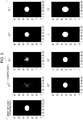
- Fig. 2 illustrates a BRDF obtained when the coefficient of the Wiener filter is kept constant regardless of the degree of diffusion.
- the BRDF obtained when the aperture in the aperture unit 101 is a pinhole (e.g., expressed by a ⁇ function) and the BRDF obtained when the aperture in the aperture unit 101 is an aperture (slit) defined in accordance with the specular gloss at 20 degrees in JIS Z 8741 are illustrated for different degrees of diffusion (Gaussian radius).
- the focal lengths of the condenser lenses 102 and 103 are both 15.5 mm
- the aperture in the aperture unit 101 is an aperture defined in accordance with the specular gloss at 20 degrees in JIS Z 8741 (finite aperture)
- the (primary) light source is a D65 light source
- the dimensions of each pixel in the imaging device 3 are 7.4 ⁇ m by 59.2 ⁇ m.
- the coefficient of the Wiener filter is 10 -4 .
- the BRDFs in Fig. 2 are each binarized with the median value of the BRDF serving as a threshold.
- A represents a coefficient for normalizing the reflectance.
- the BRDF deviates from the BRDF in the case of the pinhole in accordance with the degree of diffusion ⁇ , and the deviation is greater in particular as the degree of diffusion ⁇ is greater. In this manner, when the coefficient of the Wiener filter is fixed, an appropriate BRDF may not be obtained.
- Fig. 3 illustrates the BRDF obtained when the coefficient of the Wiener filter is varied. In this case, the degree of diffusion ⁇ is set to 1.0, and the coefficient c is varied.
- step S3 the degree of diffusion ⁇ is estimated, and the coefficient c of the Wiener filter is determined on the basis of the estimated degree of diffusion ⁇ .
- step S4 the Wiener filter is determined on the basis of the coefficient c determined in S3. More specifically, in step S3, a provisional BRDF can be obtained on the basis of a provisional Wiener coefficient c determined in advance, and the degree of diffusion ⁇ can be estimated on the basis of the provisional BRDF. Alternatively, the degree of diffusion ⁇ can be estimated on the basis of a correlation (e.g., a correlation coefficient) between the aperture g and the image i.
- a correlation e.g., a correlation coefficient
- the degree of diffusion of the sample may be estimated on the basis of one of the image and a Fourier transform thereof and one of the (secondary) light source corresponding thereto and a Fourier transform thereof.
- step S5 b(01,02) as the BRDF of the sample 2 is obtained by subjecting B(m,n), which is a Fourier transform of the BRDF, to an inverse Fourier transform, as in the following expression.
- B(m,n) which is a Fourier transform of the BRDF
- b( ⁇ 1, ⁇ 2) as the BRDF of the sample 2 generally takes a nonnegative value, but the BRDF obtained through the expression (4) may take a negative value.
- the absolute value of such a negative value is small when an appropriate Wiener filter is selected, and thus even when such a negative value is turned into a nonnegative value (i.e., rounding to 0 or turning it into a positive value by taking its absolute value), an influence of such an operation may be negligible.
- an appropriate BRDF can be obtained.
- a measuring apparatus that is advantageous in terms of the angular resolution of an obtained optical characteristic can be provided.
- the sample may transmit light (the optical characteristic obtained in this case are bidirectional transmittance distribution function (BTDF)).
- BTDF bidirectional transmittance distribution function
- the reflection characteristic (reflectance) have been described as an example, the present invention is not limited thereto, and the reflection characteristic (reflectance) may be converted to an absorption characteristic (absorptance).
- Fig. 4 illustrates an example of the flow of the process of determining the coefficient of the Wiener filter. Specifically, Fig. 4 illustrates a specific example of the flow of the process in step S3 of Fig. 1B .
- a provisional coefficient c of the Wiener filter is set to a provisional value (predetermined value) determined in advance.
- the focal lengths of the condenser lenses 102 and 103 are both 15.5 mm
- the aperture in the aperture unit 101 is an aperture in accordance with the specular gloss at 20 degrees defined by JIS Z 8741 (finite aperture)
- the primary light source is a D65 light source
- the dimensions of each pixel in the imaging device 3 are 7.4 ⁇ m by 59.2 ⁇ m.
- the provisional coefficient c of the Wiener filter preferably takes a value within a range from 10 -3 to 10 -1 inclusive.
- the provisional coefficient c preferably takes a value within a range from 10 -2 to 1 inclusive.
- step S3-2 a provisional BRDF is obtained on the basis of the provisional filter coefficient c, and a provisional value of the degree of diffusion ⁇ is obtained.
- the provisional filter coefficient c is set to 10 -3 .
- the BRDF is obtained through the expressions (2) and (4) with the use of the provisional filter coefficient c, and the obtained BRDF is fitted through the expression (3).
- provisional values of the degree of diffusion ⁇ can be obtained as indicated in Table 1.
- the aforementioned fitting may be carried out on the degree of diffusion ⁇ with the use of a Gaussian function (the right-hand side of the expression (3)) having the degree of diffusion ⁇ in the form of a Gaussian radius as an unknown.
- Table 1 DEGREE OF DIFFUSION ⁇ PROVISIONAL VALUE OF ⁇ 0.010 0.037 0.020 0.045 0.030 0.052 0.040 0.059 0.050 0.067 0.100 0.117 0.200 0.219 0.300 0.312 0.400 0.415 0.500 0.519 1.000 1.034 2.000 2.032 4.000 4.020
- step S3-3 the coefficient c of the Wiener filter is determined on the basis of the provisional value of the degree of diffusion ⁇ obtained in S3-2 with reference to Table 1 and Table 2.
- Table 2 indicates preferable coefficients (common logarithms) of the Wiener filter obtained in advance with respect to the degree of diffusion ⁇ of the sample 2.
- Table 2 DEGREE OF DIFFUSION ⁇ Log 10 (c) 0.01 -8 0.02 -8 0.03 -8 0.04 -8 0.05 -7 0.1 -6 0.2 -5 0.3 -4 0.4 -4 0.5 -3 1 -3 2 -3 4 -3
- Fig. 5 illustrates the degree of diffusion that is based on the BRDF obtained by using the provisional coefficient or the determined coefficient. As compared with (the provisional value of) the degree of diffusion ⁇ obtained from the provisional coefficient, the degree of diffusion ⁇ obtained from the determined coefficient is close to the actual degree of diffusion ⁇ of the sample. This reveals that an effective BRDF can be obtained even when a finite aperture instead of a pinhole is used as the aperture in the aperture unit 101.
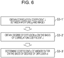
- Fig. 6 illustrates another example of the flow of the process of determining the coefficient of the Wiener filter.
- step S3-1' a correlation (correlation coefficient J in this case) between the aperture g in the aperture unit 101 and the image i is obtained.
- g 0 represents a mean value of g(x,y)
- i 0 represents a mean value of i(x,y).
- step S3-2' the degree of diffusion ⁇ is obtained on the basis of the correlation coefficient J obtained through the expression (5) with reference to the relations indicated in Table 3 obtained in advance.
- the relations indicated in Table 3 are obtained under the same condition as the first example.
- Table 3 DEGREE OF DIFFUSION ⁇ CORRELATION COEFFICIENT J 0.01 1.000 0.02 1.000 0.03 0.999 0.04 0.999 0.05 0.997 0.1 0.989 0.2 0.964 0.3 0.926 0.4 0.876 0.5 0.825 1 0.628 2 0.437 4 0.339
- step S3-3' as in the first example, the coefficient c of the Wiener filter is determined on the basis of the degree of diffusion ⁇ obtained in step S3-2' and the relations indicated in Table 2.
- the aperture (slit) in the aperture unit 101 may be rectangular having different dimensions, may be circular, or may have yet another shape.
- the angle is not limited to 20 degrees, and various other angles may be employed.
- the angle may be any angle between 18 and 22 degrees; any angle between 15 and 25 degrees; any angle between 10 and 30 degrees.
- the angle of aperture 113 on the light-projection side, the angle of aperture 114 on the light-receiving side, the (primary) light source 1, the aperture in the aperture unit 101, and the angle of incidence of light incident on the sample (the angle of reflection of light from the sample) according to the first exemplary embodiment are configured so as to comply with any one of the JIS standards and the ISO standards.
- Such a configuration makes it possible to output a measurement value in accordance with such standards and to output a general index, such as a BRDF.
- a configuration compliant with JIS Z 8741 may be employed.
- a configuration compliant with ASTM E430 may be employed, or in order to output an image clarity as a measurement value, a configuration compliant with JIS K 7374 may be employed.
- a general index such as a BRDF
- processing that follows the flow of the process described with reference to Fig. 1B , Fig. 4 , or Fig. 6 in the first exemplary embodiment may be carried out.
- the processor 4 may obtain a BRDF as the optical characteristic and may obtain at least one of the gloss, the haze, the DOI, and the image clarity as the optical characteristic on the basis of the obtained BRDF.
- an image of the aperture may be taken (computed) from the aperture (e.g., g(x,y) described above) in the aperture unit 101 that is compliant with the standards and the BRDF (e.g., b( ⁇ 1, ⁇ 2) described above), and the optical characteristic compliant with the standards may be obtained on the basis of the stated image.
- the aperture e.g., g(x,y) described above
- the BRDF e.g., b( ⁇ 1, ⁇ 2) described above
- the optical characteristic may be obtained through the expression (2) after (the influence of) the aberration on the image (e.g., i(x,y) or I(m,n) described above) obtained through the optical system has been compensated for.
- the optical characteristic may be obtained through the expression (2) after (the influence of) the aberration on the image (e.g., i(x,y) or I(m,n) described above) obtained through the optical system has been compensated for.
- a Wiener filter that is based on the characteristic of the stated aberration (transfer function)
- a restored (recovered) image I'(m,n) of which aberration has been compensated for may be used in place of I(m,n).
- the degree of diffusion of the sample is estimated on the basis of one of the image and the Fourier transform thereof and one of the light source corresponding thereto and the Fourier transform thereof, and the coefficient of the Wiener filter is determined on the basis of the degree of diffusion obtained from the estimation.
- the coefficient may be determined not on the basis of (the estimated value) of the degree of diffusion of the sample but on the basis of other information (data), such as information correlated to (the estimated value) of the degree of diffusion.
- the coefficient may be determined on the basis of at least one of the provisional BRDF described above and the correlation coefficient.
- the coefficient may be determined on the basis of one of the image used to obtain the provisional BRDF and the correlation coefficient and the Fourier transform thereof or a feature amount thereof and one of the light source corresponding thereto and the Fourier transform thereof or a feature amount thereof.
- the information in Table 2 that indicates coefficients (their common logarithms) suitable for the degree of diffusion of the sample is obtained in advance, but the present invention is not limited thereto and does not exclude a mode in which such information is obtained for each instance. This also applies in a case in which other information different from (the estimated value) of the degree of diffusion of the sample as described above is used.
- Embodiment(s) of the present invention can also be realized by a computer of a system or apparatus that reads out and executes computer executable instructions (e.g., one or more programs) recorded on a storage medium (which may also be referred to more fully as a 'non-transitory computer-readable storage medium') to perform the functions of one or more of the above-described embodiment(s) and/or that includes one or more circuits (e.g., application specific integrated circuit (ASIC)) for performing the functions of one or more of the above-described embodiment(s), and by a method performed by the computer of the system or apparatus by, for example, reading out and executing the computer executable instructions from the storage medium to perform the functions of one or more of the above-described embodiment(s) and/or controlling the one or more circuits to perform the functions of one or more of the above-described embodiment(s).
- computer executable instructions e.g., one or more programs
- a storage medium which may also be referred to more fully as
- the computer may comprise one or more processors (e.g., central processing unit (CPU), micro processing unit (MPU)) and may include a network of separate computers or separate processors to read out and execute the computer executable instructions.
- the computer executable instructions may be provided to the computer, for example, from a network or the storage medium.
- the storage medium may include, for example, one or more of a hard disk, a random-access memory (RAM), a read only memory (ROM), a storage of distributed computing systems, an optical disk (such as a compact disc (CD), digital versatile disc (DVD), or Blu-ray Disc (BD)TM), a flash memory device, a memory card, and the like.
Landscapes
- Physics & Mathematics (AREA)
- General Physics & Mathematics (AREA)
- Engineering & Computer Science (AREA)
- General Health & Medical Sciences (AREA)
- Analytical Chemistry (AREA)
- Biochemistry (AREA)
- Chemical & Material Sciences (AREA)
- Life Sciences & Earth Sciences (AREA)
- Immunology (AREA)
- Pathology (AREA)
- Health & Medical Sciences (AREA)
- Theoretical Computer Science (AREA)
- Computer Vision & Pattern Recognition (AREA)
- Mathematical Physics (AREA)
- Investigating Or Analysing Materials By Optical Means (AREA)
Description
- The present invention relates to, for example, a measuring apparatus for measuring an optical characteristic of a sample.
- Conventionally, for the purpose of evaluating the appearances of print materials, coated surfaces, and products, for example, standards for evaluating the optical characteristic of samples (their surfaces, their interiors, and so on) are being defined by JIS and ISO. For example, ISO 2813 and JIS Z 8741 define the specular gloss. ASTM E430 defines the haze and the distinctness of image (DOI). In addition, JIS K 7374 and ASTM D5767 define the image clarity. Furthermore, a unique index for evaluating the glossiness is also being proposed. Measuring apparatuses that obtain such a diffusion characteristic or an optical characteristic of samples are known. Such measuring apparatuses include an apparatus configured in accordance with a specific standard. Meanwhile, such measuring apparatuses include an apparatus that first obtains the diffusion characteristic (e.g., a bidirectional reflectance distribution function (abbreviated as BRDF)). This apparatus may function as a general-purpose apparatus that obtains a plurality of additional indices (e.g., the specular gloss, the haze, and the image clarity) on the basis of the diffusion characteristic. In an optical system in such a general-purpose measuring apparatus, a sample may be disposed in the pupil, a secondary light source may be provided at the anterior focal point, and an image sensor may be provided at the posterior focal point.
- Japanese Patent Laid-Open No.
2010-276492 2008-256454 - Increasing the angle of the aperture in the aperture plate provides an advantage in securing the quantity of light but suffers from a disadvantage in the angular resolution of the obtained optical characteristic, such as the diffusion characteristic.
-
EP2 749 865 discloses a measuring apparatus as claimed in the pre-characterizing portion of claim 1 herein, without however disclosing any use of a Wiener filter. - The present invention provides, for example, a measuring apparatus advantageous in angular resolution of an obtained optical characteristic.
- The present invention in its first aspect provides a measuring apparatus as specified in claims 1 to 4.
- The present invention in its second aspect provides a measuring method as specified in
claim 5. - The present invention in its third aspect provides a computer program as specified in claim 6.
- The present invention in its fourth aspect provides a readable storage medium as specified in claim 7.
- Further features of the present invention will become apparent from the following description of exemplary embodiments with reference to the attached drawings.
-
-
Fig. 1A illustrates a configuration example of a measuring apparatus, andFig. 1B illustrates a flow of a process executed by a processor. -
Fig. 2 illustrates a BRDF obtained when a coefficient of a Wiener filter is kept constant regardless of the degree of diffusion. -
Fig. 3 illustrates a BRDF obtained when a coefficient of a Wiener filter is varied. -
Fig. 4 illustrates an example of a flow of a process of determining a coefficient of a Wiener filter. -
Fig. 5 illustrates the degree of diffusion that is based on a BRDF obtained with the use of a provisional coefficient or a determined coefficient. -
Fig. 6 illustrates another example of a flow of a process of determining a coefficient of a Wiener filter. - Hereinafter, exemplary embodiments of the present invention will be described with reference to the accompanying drawings. It is to be noted that, throughout the drawings for describing the exemplary embodiments, in general (unless indicated otherwise), identical members are given identical reference characters, and duplicate descriptions thereof will be omitted.
-
Fig. 1A illustrates a configuration example of a measuring apparatus according to an exemplary embodiment.Fig. 1A is a sectional view of the measuring apparatus. The measuring apparatus includes an optical system (having an optical axis 110) that includes anaperture unit 101 having an aperture (also referred to as a light source or a secondary light source) andcondenser lenses sample 2 and receives light via thesample 2. A light source 1 (a real light source or a primary light source) illuminates the aperture in theaperture unit 101, for example, via another optical system (not illustrated). Thesample 2 is disposed in the pupil (or at a position near the pupil) of the optical system. Animaging device 3 takes an image of the aperture (light source) in theaperture unit 101 via the optical system. Thecondenser lens 103 is configured to receive specular reflection light (112) produced as light (111) from thecondenser lens 102 is specularly reflected by thesample 2. The aperture in theaperture unit 101 has an angle of aperture (angle of aperture on the light-projection side) 113 as viewed from thecondenser lens 102. In addition, the light-receiving area of theimaging device 3 has an angle of aperture (angle of aperture on the light-receiving side) 114 as viewed from thecondenser lens 103, and the stated angle ofaperture 114 is determined by the product of the optical magnification of the optical system and the angle ofaperture 113 on the light-projection side. It is preferable that theaperture unit 101 and theimaging device 3 be in an optically conjugate relationship. Theimaging device 3 may include a solid-state image sensor of a charge-coupled device (CCD) or complementary metal-oxide semiconductor (CMOS) structure. In particular, a structure in which pixels are arranged in a matrix is preferable. Theimaging device 3 is connected to a (signal) processor 4 (arithmetic device) via acable 5. Theprocessor 4 obtains the optical characteristic (e.g., diffusion characteristic) of thesample 2 on the basis of an output (signal) from theimaging device 3. Theprocessor 4 may include, but is not limited to, a computer (or an information processing device that includes a device (processor or the like), such as a central processing unit (CPU)) that operates in accordance with a program corresponding to the flow of the process illustrated inFig. 1B ,Fig. 4 , orFig. 6 , which will be described later. -
Fig. 1B illustrates a flow of a process executed by theprocessor 4. Referring toFig. 1B , in step S1, information on the aperture g(x,y) in theaperture unit 101 and information on an image i(x,y) of the aperture taken by theimaging device 3 via thesample 2 are obtained. For simplicity, g(x,y) and i(x,y) are also referred to as g and i, respectively. The information on the aperture g may be a signal to be obtained by theimaging device 3 when thesample 2 is replaced with a mirror surface, or may be a signal to be obtained by directly imaging the aperture with another imaging device. - In step S2, the aperture g and the image i are subjected to a Fourier transform so as to obtain G(m,n) and I(m,n). For simplicity, G(m,n) and I(m,n) are also referred to as G and I, respectively. A Fourier transform B(m,n) (also referred to simply as B for simplicity) of a BRDF serving as an optical characteristic can be expressed through the following relation with the use of G and I.

- In the above, Nm and Nn represent, respectively, the number of pixels in the longitudinal direction and the number of pixels in the lateral direction of the
imaging device 3. In addition, Nm0 and Nn0 represent the constants for determining the center coordinates of the BRDF. With respect to B in the expression (1), G(m,n) may become 0, which causes a divergence to occur. In order to prevent such a divergence from occurring, a Wiener filter may be used as in the following expression.
- In the above, the fraction that is not present in the expression (1) corresponds to the Wiener filter, and c represents a Wiener coefficient (also referred to simply as a coefficient). The gain of the filter varies in accordance with the coefficient c. What is important here is that the value of c is determined in accordance with not only G(m,n) that is not dependent on the
sample 2 but also I(m,n) that is dependent on thesample 2. Specifically, an ideal value of c varies depending on the degree of diffusion (e.g., the degree of diffusion σ, which will be described later), and c cannot be set to a fixed value. For describing this point,Fig. 2 illustrates a BRDF obtained when the coefficient of the Wiener filter is kept constant regardless of the degree of diffusion. The BRDF obtained when the aperture in theaperture unit 101 is a pinhole (e.g., expressed by a δ function) and the BRDF obtained when the aperture in theaperture unit 101 is an aperture (slit) defined in accordance with the specular gloss at 20 degrees in JIS Z 8741 are illustrated for different degrees of diffusion (Gaussian radius). Here, the focal lengths of thecondenser lenses aperture unit 101 is an aperture defined in accordance with the specular gloss at 20 degrees in JIS Z 8741 (finite aperture), the (primary) light source is a D65 light source, and the dimensions of each pixel in theimaging device 3 are 7.4 µm by 59.2 µm. The coefficient of the Wiener filter is 10-4. The BRDFs inFig. 2 are each binarized with the median value of the BRDF serving as a threshold. The degree of diffusion σ of thesample 2 is given by the following expression.
- In the above, θ0 represents the specular reflection angle (= 20°), and A represents a coefficient for normalizing the reflectance. Referring to
Fig. 2 , in the case of the finite aperture, the BRDF deviates from the BRDF in the case of the pinhole in accordance with the degree of diffusion σ, and the deviation is greater in particular as the degree of diffusion σ is greater. In this manner, when the coefficient of the Wiener filter is fixed, an appropriate BRDF may not be obtained. With respect to the case of the finite aperture,Fig. 3 illustrates the BRDF obtained when the coefficient of the Wiener filter is varied. In this case, the degree of diffusion σ is set to 1.0, and the coefficient c is varied.Fig. 3 reveals that, when the coefficient c is in a range from around 10-3 to 10-2, the obtained BRDF is close to the BRDF obtained in the case of the pinhole and the deviation increases in other ranges. In other words, an appropriate BRDF may be obtained when (the coefficient c of) the Wiener filter is determined in accordance with the degree of diffusion. Referring back toFig. 1B , processing steps therefor will be described. - In step S3, the degree of diffusion σ is estimated, and the coefficient c of the Wiener filter is determined on the basis of the estimated degree of diffusion σ. In step S4, the Wiener filter is determined on the basis of the coefficient c determined in S3. More specifically, in step S3, a provisional BRDF can be obtained on the basis of a provisional Wiener coefficient c determined in advance, and the degree of diffusion σ can be estimated on the basis of the provisional BRDF. Alternatively, the degree of diffusion σ can be estimated on the basis of a correlation (e.g., a correlation coefficient) between the aperture g and the image i. Specifically, the degree of diffusion of the sample may be estimated on the basis of one of the image and a Fourier transform thereof and one of the (secondary) light source corresponding thereto and a Fourier transform thereof. These methods will be described later in detail with specific examples in a first example and a second example.
- Lastly, in step S5, b(01,02) as the BRDF of the
sample 2 is obtained by subjecting B(m,n), which is a Fourier transform of the BRDF, to an inverse Fourier transform, as in the following expression.
- In the above, b(θ1, θ2) as the BRDF of the
sample 2 generally takes a nonnegative value, but the BRDF obtained through the expression (4) may take a negative value. However, the absolute value of such a negative value is small when an appropriate Wiener filter is selected, and thus even when such a negative value is turned into a nonnegative value (i.e., rounding to 0 or turning it into a positive value by taking its absolute value), an influence of such an operation may be negligible. In this manner, an appropriate BRDF can be obtained. Thus, a measuring apparatus that is advantageous in terms of the angular resolution of an obtained optical characteristic can be provided. - Although a case in which the sample reflects light has been illustrated as an example in the foregoing description, the present invention is not limited thereto. For example, the sample may transmit light (the optical characteristic obtained in this case are bidirectional transmittance distribution function (BTDF)). Furthermore, although the reflection characteristic (reflectance) have been described as an example, the present invention is not limited thereto, and the reflection characteristic (reflectance) may be converted to an absorption characteristic (absorptance).
-
Fig. 4 illustrates an example of the flow of the process of determining the coefficient of the Wiener filter. Specifically,Fig. 4 illustrates a specific example of the flow of the process in step S3 ofFig. 1B . In step S3-1, a provisional coefficient c of the Wiener filter is set to a provisional value (predetermined value) determined in advance. Here, the focal lengths of thecondenser lenses aperture unit 101 is an aperture in accordance with the specular gloss at 20 degrees defined by JIS Z 8741 (finite aperture), the primary light source is a D65 light source, and the dimensions of each pixel in theimaging device 3 are 7.4 µm by 59.2 µm. In this case, the provisional coefficient c of the Wiener filter preferably takes a value within a range from 10-3 to 10-1 inclusive. In addition, when the aperture (slit) in theaperture unit 101 is an aperture in accordance with the specular gloss at 60 degrees defined by JIS Z 8741, the provisional coefficient c preferably takes a value within a range from 10-2 to 1 inclusive. - In step S3-2, a provisional BRDF is obtained on the basis of the provisional filter coefficient c, and a provisional value of the degree of diffusion σ is obtained. When the aperture (slit) in the
aperture unit 101 is an aperture in accordance with the specular gloss at 20 degrees, the provisional filter coefficient c is set to 10-3. With respect to the degree of diffusion σ of the sample, the BRDF is obtained through the expressions (2) and (4) with the use of the provisional filter coefficient c, and the obtained BRDF is fitted through the expression (3). Thus, provisional values of the degree of diffusion σ can be obtained as indicated in Table 1. The aforementioned fitting may be carried out on the degree of diffusion σ with the use of a Gaussian function (the right-hand side of the expression (3)) having the degree of diffusion σ in the form of a Gaussian radius as an unknown.Table 1 DEGREE OF DIFFUSION σ PROVISIONAL VALUE OF σ 0.010 0.037 0.020 0.045 0.030 0.052 0.040 0.059 0.050 0.067 0.100 0.117 0.200 0.219 0.300 0.312 0.400 0.415 0.500 0.519 1.000 1.034 2.000 2.032 4.000 4.020 - In step S3-3, the coefficient c of the Wiener filter is determined on the basis of the provisional value of the degree of diffusion σ obtained in S3-2 with reference to Table 1 and Table 2. Table 2 indicates preferable coefficients (common logarithms) of the Wiener filter obtained in advance with respect to the degree of diffusion σ of the
sample 2.Table 2 DEGREE OF DIFFUSION σ Log10(c) 0.01 -8 0.02 -8 0.03 -8 0.04 -8 0.05 -7 0.1 -6 0.2 -5 0.3 -4 0.4 -4 0.5 -3 1 -3 2 -3 4 -3 -
Fig. 5 illustrates the degree of diffusion that is based on the BRDF obtained by using the provisional coefficient or the determined coefficient. As compared with (the provisional value of) the degree of diffusion σ obtained from the provisional coefficient, the degree of diffusion σ obtained from the determined coefficient is close to the actual degree of diffusion σ of the sample. This reveals that an effective BRDF can be obtained even when a finite aperture instead of a pinhole is used as the aperture in theaperture unit 101. -
Fig. 6 illustrates another example of the flow of the process of determining the coefficient of the Wiener filter. In step S3-1', a correlation (correlation coefficient J in this case) between the aperture g in theaperture unit 101 and the image i is obtained.
- In the above, g0 represents a mean value of g(x,y), and i0 represents a mean value of i(x,y).
- In step S3-2', the degree of diffusion σ is obtained on the basis of the correlation coefficient J obtained through the expression (5) with reference to the relations indicated in Table 3 obtained in advance. The relations indicated in Table 3 are obtained under the same condition as the first example.
Table 3 DEGREE OF DIFFUSION σ CORRELATION COEFFICIENT J 0.01 1.000 0.02 1.000 0.03 0.999 0.04 0.999 0.05 0.997 0.1 0.989 0.2 0.964 0.3 0.926 0.4 0.876 0.5 0.825 1 0.628 2 0.437 4 0.339 - In step S3-3', as in the first example, the coefficient c of the Wiener filter is determined on the basis of the degree of diffusion σ obtained in step S3-2' and the relations indicated in Table 2.
- The measurement of the specular gloss at 20 degrees has primarily been illustrated as an example in the first exemplary embodiment above, but the present invention is not limited thereto. For example, the aperture (slit) in the
aperture unit 101 may be rectangular having different dimensions, may be circular, or may have yet another shape. The angle is not limited to 20 degrees, and various other angles may be employed. For example, the angle may be any angle between 18 and 22 degrees; any angle between 15 and 25 degrees; any angle between 10 and 30 degrees. - In the present exemplary embodiment, the angle of
aperture 113 on the light-projection side, the angle ofaperture 114 on the light-receiving side, the (primary) light source 1, the aperture in theaperture unit 101, and the angle of incidence of light incident on the sample (the angle of reflection of light from the sample) according to the first exemplary embodiment are configured so as to comply with any one of the JIS standards and the ISO standards. Such a configuration makes it possible to output a measurement value in accordance with such standards and to output a general index, such as a BRDF. For example, in order to output a specular gloss as a measurement value, a configuration compliant with JIS Z 8741 may be employed. In addition, in order to output a haze as a measurement, a configuration compliant with ASTM E430 may be employed, or in order to output an image clarity as a measurement value, a configuration compliant with JIS K 7374 may be employed. In order to output a general index, such as a BRDF, in the aforementioned configuration, processing that follows the flow of the process described with reference toFig. 1B ,Fig. 4 , orFig. 6 in the first exemplary embodiment may be carried out. - Thus far, exemplary embodiments of the present invention have been described, but it is needless to say that the present invention is not limited to these exemplary embodiments, and various modifications and changes can be made within the scope of spirit of the present invention. For example, the
processor 4 may obtain a BRDF as the optical characteristic and may obtain at least one of the gloss, the haze, the DOI, and the image clarity as the optical characteristic on the basis of the obtained BRDF. In this case, an image of the aperture may be taken (computed) from the aperture (e.g., g(x,y) described above) in theaperture unit 101 that is compliant with the standards and the BRDF (e.g., b(θ1, θ2) described above), and the optical characteristic compliant with the standards may be obtained on the basis of the stated image. - In addition, when an influence of aberration of the optical system in the measuring apparatus is not negligible, the optical characteristic may be obtained through the expression (2) after (the influence of) the aberration on the image (e.g., i(x,y) or I(m,n) described above) obtained through the optical system has been compensated for. In this case, with the use of a Wiener filter that is based on the characteristic of the stated aberration (transfer function), a restored (recovered) image I'(m,n) of which aberration has been compensated for may be used in place of I(m,n).
- In addition, in the examples described above, the degree of diffusion of the sample is estimated on the basis of one of the image and the Fourier transform thereof and one of the light source corresponding thereto and the Fourier transform thereof, and the coefficient of the Wiener filter is determined on the basis of the degree of diffusion obtained from the estimation. However, the present invention is not limited thereto. For example, the coefficient may be determined not on the basis of (the estimated value) of the degree of diffusion of the sample but on the basis of other information (data), such as information correlated to (the estimated value) of the degree of diffusion. For example, the coefficient may be determined on the basis of at least one of the provisional BRDF described above and the correlation coefficient. Furthermore, the coefficient may be determined on the basis of one of the image used to obtain the provisional BRDF and the correlation coefficient and the Fourier transform thereof or a feature amount thereof and one of the light source corresponding thereto and the Fourier transform thereof or a feature amount thereof. In addition, the information in Table 2 that indicates coefficients (their common logarithms) suitable for the degree of diffusion of the sample is obtained in advance, but the present invention is not limited thereto and does not exclude a mode in which such information is obtained for each instance. This also applies in a case in which other information different from (the estimated value) of the degree of diffusion of the sample as described above is used.
- Embodiment(s) of the present invention can also be realized by a computer of a system or apparatus that reads out and executes computer executable instructions (e.g., one or more programs) recorded on a storage medium (which may also be referred to more fully as a 'non-transitory computer-readable storage medium') to perform the functions of one or more of the above-described embodiment(s) and/or that includes one or more circuits (e.g., application specific integrated circuit (ASIC)) for performing the functions of one or more of the above-described embodiment(s), and by a method performed by the computer of the system or apparatus by, for example, reading out and executing the computer executable instructions from the storage medium to perform the functions of one or more of the above-described embodiment(s) and/or controlling the one or more circuits to perform the functions of one or more of the above-described embodiment(s). The computer may comprise one or more processors (e.g., central processing unit (CPU), micro processing unit (MPU)) and may include a network of separate computers or separate processors to read out and execute the computer executable instructions. The computer executable instructions may be provided to the computer, for example, from a network or the storage medium. The storage medium may include, for example, one or more of a hard disk, a random-access memory (RAM), a read only memory (ROM), a storage of distributed computing systems, an optical disk (such as a compact disc (CD), digital versatile disc (DVD), or Blu-ray Disc (BD)™), a flash memory device, a memory card, and the like.
- While the present invention has been described with reference to exemplary embodiments, it is to be understood that the invention is not limited to the disclosed exemplary embodiments. The scope of the following claims is to be accorded the broadest interpretation so as to encompass all such modifications and equivalent structures and functions.
Claims (7)
- A measuring apparatus for measuring an optical characteristic of a sample, the optical characteristic being a bidirectional reflectance distribution function or a bidirectional transmittance distribution function, the apparatus comprising:an optical system (102, 103) configured to project light from a light source (101) onto the sample (2) and to receive light via the sample to form an image of the light source;an imaging device (3) configured to take the image of the light source (101) via the optical system, the light source being an object corresponding to the taken image with respect to the optical system; anda processor (4) configured to obtain the optical characteristic of the sample based on the taken image and a coefficient of a Wiener filter,characterized in that the processor (4) is configured to:estimate a degree of diffusion of the projected light by the sample (2) based on (i) a provisional optical characteristic obtained based on a provisional coefficient of a Wiener filter, a Fourier transform of the taken image, and a Fourier transform of the light source, or (ii) a correlation between the taken image and the light source,determine a coefficient c of the Wiener filter with respect to the estimated degree of diffusion based on data of coefficients of the Wiener filter with respect to different degrees of diffusion of a sample, andobtain a Fourier transform B(m,n) of the optical characteristic by substituting the determined coefficient c of the Wiener filter, the Fourier transform I(m,n) of the taken image and the Fourier transform G(m,n) of the light source into the expression

- The measuring apparatus according to Claim 1, wherein the processor (4) is configured to obtain the estimated degree of diffusion based on a Gaussian function having the estimated degree of diffusion as an unknown Gaussian radius and a bidirectional reflectance distribution function.
- The measuring apparatus according to Claim 1, wherein the processor (4) is configured to obtain, as the correlation, a correlation coefficient between the taken image and the light source.
- The measuring apparatus according to Claim 1, wherein the processor (4) estimates the degree of diffusion of the sample (2) by(i) substituting a provisional coefficient c of a Wiener filter, a Fourier transform I(m,n) of the taken image and a Fourier transform G(m,n) of the light source into the expression
 (ii) obtaining a correlation coefficient between the taken image and the light source, and by obtaining the degree of diffusion of the sample with respect to the obtained correlation coefficient based on data of different degrees of diffusion of the sample with respect to different correlation coefficients between the light source and an image of the light source.
 - A method of obtaining an optical characteristic of a sample, the optical characteristic being a bidirectional reflectance distribution function or a bidirectional transmittance distribution function, wherein light from a light source (101) has been projected onto the sample (2), light via the sample has been received to form an image of the light source, via an optical system, the image of the light source (101) has been taken via the optical system to obtain the optical characteristic of the sample based on the taken image and a coefficient of a Wiener filter, the light source being an object corresponding to the taken image with respect to the optical system, the method comprising steps of:estimating a degree of diffusion of the projected light by the sample (2) based on (i) a provisional optical characteristic obtained based on a provisional coefficient of a Wiener filter, a Fourier transform of the taken image, and a Fourier transform of the light source, or (ii) a correlation between the taken image and the light source,determining a coefficient c of the Wiener filter with respect to the estimated degree of diffusion based on data of coefficients of the Wiener filter with respect to different degrees of diffusion of the sample, andobtaining a Fourier transform B(m,n) of the optical characteristic by substituting the determined coefficient c of the Wiener filter, the Fourier transform I(m,n) of the taken image and the Fourier transform G(m,n) of the light source into the expression

- A computer program for causing a measuring apparatus to execute the steps of a method according to claim 5.
- A computer-readable storage medium storing the computer program of claim 6.
Applications Claiming Priority (1)
| Application Number | Priority Date | Filing Date | Title |
|---|---|---|---|
| JP2015096830A JP6635674B2 (en) | 2015-05-11 | 2015-05-11 | Measuring device, measuring method and program |
Publications (2)
| Publication Number | Publication Date |
|---|---|
| EP3093650A1 EP3093650A1 (en) | 2016-11-16 |
| EP3093650B1 true EP3093650B1 (en) | 2021-04-07 |
Family
ID=55952984
Family Applications (1)
| Application Number | Title | Priority Date | Filing Date |
|---|---|---|---|
| EP16167764.6A Active EP3093650B1 (en) | 2015-05-11 | 2016-04-29 | Measuring apparatus, measuring method, and program |
Country Status (5)
| Country | Link |
|---|---|
| US (1) | US10235743B2 (en) |
| EP (1) | EP3093650B1 (en) |
| JP (1) | JP6635674B2 (en) |
| KR (1) | KR102052431B1 (en) |
| CN (1) | CN106153579B (en) |
Families Citing this family (6)
| Publication number | Priority date | Publication date | Assignee | Title |
|---|---|---|---|---|
| JP6557688B2 (en) | 2017-01-13 | 2019-08-07 | キヤノン株式会社 | Measuring device, information processing device, information processing method, and program |
| JP2019207175A (en) | 2018-05-30 | 2019-12-05 | キヤノン株式会社 | Measurement device |
| JP7087687B2 (en) * | 2018-06-01 | 2022-06-21 | 株式会社サタケ | Grain gloss measuring device |
| JP7446725B2 (en) | 2019-06-28 | 2024-03-11 | キヤノン株式会社 | Measuring device, measuring method, and program |
| FR3101173B1 (en) * | 2019-09-19 | 2021-08-27 | Aryballe Tech | Odor identification device, odor identification method and corresponding computer program |
| FR3101174B1 (en) * | 2019-09-19 | 2021-08-27 | Aryballe Tech | Odor detection device, odor detection method and corresponding computer program |
Citations (2)
| Publication number | Priority date | Publication date | Assignee | Title |
|---|---|---|---|---|
| US7228005B1 (en) * | 2002-06-17 | 2007-06-05 | National Security Technologies, Llc | Adaptive wiener image restoration kernel |
| US20090080790A1 (en) * | 2007-09-21 | 2009-03-26 | Sony Corporation | Image processing apparatus, image processing method, image processing program, and image capturing apparatus |
Family Cites Families (18)
| Publication number | Priority date | Publication date | Assignee | Title |
|---|---|---|---|---|
| WO1995016259A1 (en) * | 1993-12-06 | 1995-06-15 | Philips Electronics N.V. | A noise reduction system and device, and a mobile radio station |
| US5694484A (en) * | 1995-05-15 | 1997-12-02 | Polaroid Corporation | System and method for automatically processing image data to provide images of optimal perceptual quality |
| US6608676B1 (en) * | 1997-08-01 | 2003-08-19 | Kla-Tencor Corporation | System for detecting anomalies and/or features of a surface |
| US6201601B1 (en) * | 1997-09-19 | 2001-03-13 | Kla-Tencor Corporation | Sample inspection system |
| SE9900276L (en) * | 1999-01-28 | 2000-01-10 | Skogsind Tekn Foskningsinst | Topographic determination of a surface illuminated by incident light |
| DE19909534B4 (en) * | 1999-03-04 | 2011-07-07 | BYK-Gardner GmbH, 82538 | Apparatus and method for determining the quality of structured surfaces |
| US6993204B1 (en) * | 2002-01-04 | 2006-01-31 | Pixon Llc | High speed signal enhancement using pixons |
| US7181085B1 (en) * | 2002-04-04 | 2007-02-20 | Acorn Technologies, Inc. | Adaptive multistage wiener filter |
| EP1520255A2 (en) * | 2002-06-21 | 2005-04-06 | Isis Innovation Limited | Methods of anisotropic diffusion and foveal segmentation of digital images |
| US7636489B2 (en) * | 2004-04-16 | 2009-12-22 | Apple Inc. | Blur computation algorithm |
| US7767949B2 (en) * | 2005-01-18 | 2010-08-03 | Rearden, Llc | Apparatus and method for capturing still images and video using coded aperture techniques |
| GB0608841D0 (en) * | 2006-05-04 | 2006-06-14 | Isis Innovation | Scanner system and method for scanning |
| JP2008256454A (en) | 2007-04-03 | 2008-10-23 | Konica Minolta Sensing Inc | Optical characteristic measuring device and method |
| JP5204723B2 (en) | 2009-05-29 | 2013-06-05 | 三菱製紙株式会社 | Method and apparatus for measuring specular reflected light distribution of point image |
| JP5409829B2 (en) * | 2012-02-17 | 2014-02-05 | キヤノン株式会社 | Image processing apparatus, imaging apparatus, image processing method, and program |
| JP6053506B2 (en) * | 2012-12-25 | 2016-12-27 | キヤノン株式会社 | Reflection characteristic measuring device |
| US9235283B2 (en) * | 2013-08-06 | 2016-01-12 | Apple Inc. | Electronic device including blurred finger image deblurring circuitry and related methods |
| EP3072129B1 (en) * | 2014-04-30 | 2018-06-13 | Huawei Technologies Co., Ltd. | Signal processing apparatus, method and computer program for dereverberating a number of input audio signals |
-
2015
- 2015-05-11 JP JP2015096830A patent/JP6635674B2/en active Active
-
2016
- 2016-04-29 EP EP16167764.6A patent/EP3093650B1/en active Active
- 2016-05-02 US US15/144,550 patent/US10235743B2/en active Active
- 2016-05-11 KR KR1020160057314A patent/KR102052431B1/en not_active Expired - Fee Related
- 2016-05-11 CN CN201610308070.2A patent/CN106153579B/en not_active Expired - Fee Related
Patent Citations (2)
| Publication number | Priority date | Publication date | Assignee | Title |
|---|---|---|---|---|
| US7228005B1 (en) * | 2002-06-17 | 2007-06-05 | National Security Technologies, Llc | Adaptive wiener image restoration kernel |
| US20090080790A1 (en) * | 2007-09-21 | 2009-03-26 | Sony Corporation | Image processing apparatus, image processing method, image processing program, and image capturing apparatus |
Also Published As
| Publication number | Publication date |
|---|---|
| CN106153579B (en) | 2019-07-23 |
| KR102052431B1 (en) | 2019-12-05 |
| US20160335772A1 (en) | 2016-11-17 |
| KR20160132778A (en) | 2016-11-21 |
| US10235743B2 (en) | 2019-03-19 |
| JP2016211999A (en) | 2016-12-15 |
| CN106153579A (en) | 2016-11-23 |
| JP6635674B2 (en) | 2020-01-29 |
| EP3093650A1 (en) | 2016-11-16 |
Similar Documents
| Publication | Publication Date | Title |
|---|---|---|
| EP3093650A1 (en) | Measuring apparatus, measuring method, and program | |
| Hancock et al. | Compact continuum source finding for next generation radio surveys | |
| CN111308448A (en) | Image acquisition equipment and radar external parameter determination method and device | |
| EP3513552B1 (en) | Systems and methods for improved depth sensing | |
| CN114127520A (en) | Spectrometer device | |
| US11902497B2 (en) | Depth measurement | |
| US11193756B2 (en) | Object shape measurement apparatus and method | |
| CN111986103A (en) | Image processing method, image processing device, electronic equipment and computer storage medium | |
| WO2016080442A1 (en) | Quality evaluation method and quality evaluation device | |
| Pineda et al. | Robust automated reading of the skin prick test via 3D imaging and parametric surface fitting | |
| KR102170163B1 (en) | System, method and computer program product for correcting a difference image generated from comparison of a target die and a reference die | |
| CN114203571B (en) | Systems, methods, and non-transitory computer-readable media for tuning sensitivity of a modulated wafer and determining a process window for a modulated wafer | |
| FR3078793A1 (en) | METHOD OF AUTHENTICATING A FACE BASED ON REFLECTANCE | |
| US12175635B2 (en) | Temporal metrics for denoising depth image data | |
| JP6272112B2 (en) | Distance detection device, imaging device, distance detection method, and parallax amount detection device | |
| EP3073416B1 (en) | Device for checking the veracity of a fingerprint | |
| KR102308974B1 (en) | Dangerous substance detecting system and method and computer program based visual information | |
| US20220260489A1 (en) | System and method for analyzing molecular interactions on living cells using biosensor techniques | |
| CN111062857B (en) | 3D contour camera reflected light elimination system and method | |
| Chan et al. | Laser digitizer-based sheet metal strain and surface analysis | |
| US12449316B2 (en) | Temperature measurement system, temperature measurement method, and non-transitory computer readable storage medium | |
| Letova et al. | Test object image preprocessing for modulation transfer function calculation in the testing of optical systems | |
| Xiang et al. | MTF measurement and imaging quality evaluation of digital camera with slanted-edge method | |
| US20240242536A1 (en) | Detection system and detection method | |
| Amdani et al. | An Early Validation Of Image Processing Technique For Flatness Measurement |
Legal Events
| Date | Code | Title | Description |
|---|---|---|---|
| PUAI | Public reference made under article 153(3) epc to a published international application that has entered the european phase |
Free format text: ORIGINAL CODE: 0009012 |
|
| AK | Designated contracting states |
Kind code of ref document: A1 Designated state(s): AL AT BE BG CH CY CZ DE DK EE ES FI FR GB GR HR HU IE IS IT LI LT LU LV MC MK MT NL NO PL PT RO RS SE SI SK SM TR |
|
| AX | Request for extension of the european patent |
Extension state: BA ME |
|
| STAA | Information on the status of an ep patent application or granted ep patent |
Free format text: STATUS: REQUEST FOR EXAMINATION WAS MADE |
|
| 17P | Request for examination filed |
Effective date: 20170516 |
|
| RBV | Designated contracting states (corrected) |
Designated state(s): AL AT BE BG CH CY CZ DE DK EE ES FI FR GB GR HR HU IE IS IT LI LT LU LV MC MK MT NL NO PL PT RO RS SE SI SK SM TR |
|
| STAA | Information on the status of an ep patent application or granted ep patent |
Free format text: STATUS: EXAMINATION IS IN PROGRESS |
|
| 17Q | First examination report despatched |
Effective date: 20191008 |
|
| REG | Reference to a national code |
Ref country code: DE Ref legal event code: R079 Ref document number: 602016055518 Country of ref document: DE Free format text: PREVIOUS MAIN CLASS: G01N0021550000 Ipc: G06T0007320000 |
|
| GRAP | Despatch of communication of intention to grant a patent |
Free format text: ORIGINAL CODE: EPIDOSNIGR1 |
|
| STAA | Information on the status of an ep patent application or granted ep patent |
Free format text: STATUS: GRANT OF PATENT IS INTENDED |
|
| RIC1 | Information provided on ipc code assigned before grant |
Ipc: G06T 7/32 20170101AFI20201014BHEP Ipc: G06T 7/37 20170101ALI20201014BHEP Ipc: G01N 21/55 20140101ALI20201014BHEP Ipc: G01N 21/57 20060101ALI20201014BHEP |
|
| INTG | Intention to grant announced |
Effective date: 20201112 |
|
| GRAS | Grant fee paid |
Free format text: ORIGINAL CODE: EPIDOSNIGR3 |
|
| GRAA | (expected) grant |
Free format text: ORIGINAL CODE: 0009210 |
|
| STAA | Information on the status of an ep patent application or granted ep patent |
Free format text: STATUS: THE PATENT HAS BEEN GRANTED |
|
| AK | Designated contracting states |
Kind code of ref document: B1 Designated state(s): AL AT BE BG CH CY CZ DE DK EE ES FI FR GB GR HR HU IE IS IT LI LT LU LV MC MK MT NL NO PL PT RO RS SE SI SK SM TR |
|
| REG | Reference to a national code |
Ref country code: GB Ref legal event code: FG4D |
|
| REG | Reference to a national code |
Ref country code: AT Ref legal event code: REF Ref document number: 1380680 Country of ref document: AT Kind code of ref document: T Effective date: 20210415 Ref country code: CH Ref legal event code: EP |
|
| REG | Reference to a national code |
Ref country code: DE Ref legal event code: R096 Ref document number: 602016055518 Country of ref document: DE |
|
| REG | Reference to a national code |
Ref country code: IE Ref legal event code: FG4D |
|
| REG | Reference to a national code |
Ref country code: LT Ref legal event code: MG9D |
|
| REG | Reference to a national code |
Ref country code: NL Ref legal event code: MP Effective date: 20210407 Ref country code: AT Ref legal event code: MK05 Ref document number: 1380680 Country of ref document: AT Kind code of ref document: T Effective date: 20210407 |
|
| PG25 | Lapsed in a contracting state [announced via postgrant information from national office to epo] |
Ref country code: HR Free format text: LAPSE BECAUSE OF FAILURE TO SUBMIT A TRANSLATION OF THE DESCRIPTION OR TO PAY THE FEE WITHIN THE PRESCRIBED TIME-LIMIT Effective date: 20210407 Ref country code: AT Free format text: LAPSE BECAUSE OF FAILURE TO SUBMIT A TRANSLATION OF THE DESCRIPTION OR TO PAY THE FEE WITHIN THE PRESCRIBED TIME-LIMIT Effective date: 20210407 Ref country code: BG Free format text: LAPSE BECAUSE OF FAILURE TO SUBMIT A TRANSLATION OF THE DESCRIPTION OR TO PAY THE FEE WITHIN THE PRESCRIBED TIME-LIMIT Effective date: 20210707 Ref country code: NL Free format text: LAPSE BECAUSE OF FAILURE TO SUBMIT A TRANSLATION OF THE DESCRIPTION OR TO PAY THE FEE WITHIN THE PRESCRIBED TIME-LIMIT Effective date: 20210407 Ref country code: LT Free format text: LAPSE BECAUSE OF FAILURE TO SUBMIT A TRANSLATION OF THE DESCRIPTION OR TO PAY THE FEE WITHIN THE PRESCRIBED TIME-LIMIT Effective date: 20210407 Ref country code: FI Free format text: LAPSE BECAUSE OF FAILURE TO SUBMIT A TRANSLATION OF THE DESCRIPTION OR TO PAY THE FEE WITHIN THE PRESCRIBED TIME-LIMIT Effective date: 20210407 |
|
| REG | Reference to a national code |
Ref country code: DE Ref legal event code: R119 Ref document number: 602016055518 Country of ref document: DE |
|
| PG25 | Lapsed in a contracting state [announced via postgrant information from national office to epo] |
Ref country code: GR Free format text: LAPSE BECAUSE OF FAILURE TO SUBMIT A TRANSLATION OF THE DESCRIPTION OR TO PAY THE FEE WITHIN THE PRESCRIBED TIME-LIMIT Effective date: 20210708 Ref country code: IS Free format text: LAPSE BECAUSE OF FAILURE TO SUBMIT A TRANSLATION OF THE DESCRIPTION OR TO PAY THE FEE WITHIN THE PRESCRIBED TIME-LIMIT Effective date: 20210807 Ref country code: LV Free format text: LAPSE BECAUSE OF FAILURE TO SUBMIT A TRANSLATION OF THE DESCRIPTION OR TO PAY THE FEE WITHIN THE PRESCRIBED TIME-LIMIT Effective date: 20210407 Ref country code: ES Free format text: LAPSE BECAUSE OF FAILURE TO SUBMIT A TRANSLATION OF THE DESCRIPTION OR TO PAY THE FEE WITHIN THE PRESCRIBED TIME-LIMIT Effective date: 20210407 Ref country code: PT Free format text: LAPSE BECAUSE OF FAILURE TO SUBMIT A TRANSLATION OF THE DESCRIPTION OR TO PAY THE FEE WITHIN THE PRESCRIBED TIME-LIMIT Effective date: 20210809 Ref country code: PL Free format text: LAPSE BECAUSE OF FAILURE TO SUBMIT A TRANSLATION OF THE DESCRIPTION OR TO PAY THE FEE WITHIN THE PRESCRIBED TIME-LIMIT Effective date: 20210407 Ref country code: NO Free format text: LAPSE BECAUSE OF FAILURE TO SUBMIT A TRANSLATION OF THE DESCRIPTION OR TO PAY THE FEE WITHIN THE PRESCRIBED TIME-LIMIT Effective date: 20210707 Ref country code: RS Free format text: LAPSE BECAUSE OF FAILURE TO SUBMIT A TRANSLATION OF THE DESCRIPTION OR TO PAY THE FEE WITHIN THE PRESCRIBED TIME-LIMIT Effective date: 20210407 Ref country code: SE Free format text: LAPSE BECAUSE OF FAILURE TO SUBMIT A TRANSLATION OF THE DESCRIPTION OR TO PAY THE FEE WITHIN THE PRESCRIBED TIME-LIMIT Effective date: 20210407 |
|
| PG25 | Lapsed in a contracting state [announced via postgrant information from national office to epo] |
Ref country code: LU Free format text: LAPSE BECAUSE OF NON-PAYMENT OF DUE FEES Effective date: 20210429 |
|
| REG | Reference to a national code |
Ref country code: BE Ref legal event code: MM Effective date: 20210430 |
|
| PG25 | Lapsed in a contracting state [announced via postgrant information from national office to epo] |
Ref country code: SM Free format text: LAPSE BECAUSE OF FAILURE TO SUBMIT A TRANSLATION OF THE DESCRIPTION OR TO PAY THE FEE WITHIN THE PRESCRIBED TIME-LIMIT Effective date: 20210407 Ref country code: SK Free format text: LAPSE BECAUSE OF FAILURE TO SUBMIT A TRANSLATION OF THE DESCRIPTION OR TO PAY THE FEE WITHIN THE PRESCRIBED TIME-LIMIT Effective date: 20210407 Ref country code: CZ Free format text: LAPSE BECAUSE OF FAILURE TO SUBMIT A TRANSLATION OF THE DESCRIPTION OR TO PAY THE FEE WITHIN THE PRESCRIBED TIME-LIMIT Effective date: 20210407 Ref country code: DK Free format text: LAPSE BECAUSE OF FAILURE TO SUBMIT A TRANSLATION OF THE DESCRIPTION OR TO PAY THE FEE WITHIN THE PRESCRIBED TIME-LIMIT Effective date: 20210407 Ref country code: EE Free format text: LAPSE BECAUSE OF FAILURE TO SUBMIT A TRANSLATION OF THE DESCRIPTION OR TO PAY THE FEE WITHIN THE PRESCRIBED TIME-LIMIT Effective date: 20210407 Ref country code: DE Free format text: LAPSE BECAUSE OF NON-PAYMENT OF DUE FEES Effective date: 20211103 Ref country code: RO Free format text: LAPSE BECAUSE OF FAILURE TO SUBMIT A TRANSLATION OF THE DESCRIPTION OR TO PAY THE FEE WITHIN THE PRESCRIBED TIME-LIMIT Effective date: 20210407 Ref country code: CH Free format text: LAPSE BECAUSE OF NON-PAYMENT OF DUE FEES Effective date: 20210430 Ref country code: MC Free format text: LAPSE BECAUSE OF FAILURE TO SUBMIT A TRANSLATION OF THE DESCRIPTION OR TO PAY THE FEE WITHIN THE PRESCRIBED TIME-LIMIT Effective date: 20210407 Ref country code: LI Free format text: LAPSE BECAUSE OF NON-PAYMENT OF DUE FEES Effective date: 20210430 |
|
| PLBE | No opposition filed within time limit |
Free format text: ORIGINAL CODE: 0009261 |
|
| STAA | Information on the status of an ep patent application or granted ep patent |
Free format text: STATUS: NO OPPOSITION FILED WITHIN TIME LIMIT |
|
| 26N | No opposition filed |
Effective date: 20220110 |
|
| PG25 | Lapsed in a contracting state [announced via postgrant information from national office to epo] |
Ref country code: IE Free format text: LAPSE BECAUSE OF NON-PAYMENT OF DUE FEES Effective date: 20210429 |
|
| PG25 | Lapsed in a contracting state [announced via postgrant information from national office to epo] |
Ref country code: IS Free format text: LAPSE BECAUSE OF FAILURE TO SUBMIT A TRANSLATION OF THE DESCRIPTION OR TO PAY THE FEE WITHIN THE PRESCRIBED TIME-LIMIT Effective date: 20210807 Ref country code: FR Free format text: LAPSE BECAUSE OF NON-PAYMENT OF DUE FEES Effective date: 20210607 Ref country code: AL Free format text: LAPSE BECAUSE OF FAILURE TO SUBMIT A TRANSLATION OF THE DESCRIPTION OR TO PAY THE FEE WITHIN THE PRESCRIBED TIME-LIMIT Effective date: 20210407 |
|
| PG25 | Lapsed in a contracting state [announced via postgrant information from national office to epo] |
Ref country code: IT Free format text: LAPSE BECAUSE OF FAILURE TO SUBMIT A TRANSLATION OF THE DESCRIPTION OR TO PAY THE FEE WITHIN THE PRESCRIBED TIME-LIMIT Effective date: 20210407 Ref country code: BE Free format text: LAPSE BECAUSE OF NON-PAYMENT OF DUE FEES Effective date: 20210430 |
|
| PG25 | Lapsed in a contracting state [announced via postgrant information from national office to epo] |
Ref country code: HU Free format text: LAPSE BECAUSE OF FAILURE TO SUBMIT A TRANSLATION OF THE DESCRIPTION OR TO PAY THE FEE WITHIN THE PRESCRIBED TIME-LIMIT; INVALID AB INITIO Effective date: 20160429 |
|
| PGFP | Annual fee paid to national office [announced via postgrant information from national office to epo] |
Ref country code: GB Payment date: 20230321 Year of fee payment: 8 |
|
| PG25 | Lapsed in a contracting state [announced via postgrant information from national office to epo] |
Ref country code: CY Free format text: LAPSE BECAUSE OF FAILURE TO SUBMIT A TRANSLATION OF THE DESCRIPTION OR TO PAY THE FEE WITHIN THE PRESCRIBED TIME-LIMIT Effective date: 20210407 |
|
| PG25 | Lapsed in a contracting state [announced via postgrant information from national office to epo] |
Ref country code: MK Free format text: LAPSE BECAUSE OF FAILURE TO SUBMIT A TRANSLATION OF THE DESCRIPTION OR TO PAY THE FEE WITHIN THE PRESCRIBED TIME-LIMIT Effective date: 20210407 |
|
| PG25 | Lapsed in a contracting state [announced via postgrant information from national office to epo] |
Ref country code: TR Free format text: LAPSE BECAUSE OF FAILURE TO SUBMIT A TRANSLATION OF THE DESCRIPTION OR TO PAY THE FEE WITHIN THE PRESCRIBED TIME-LIMIT Effective date: 20210407 |
|
| PG25 | Lapsed in a contracting state [announced via postgrant information from national office to epo] |
Ref country code: MT Free format text: LAPSE BECAUSE OF FAILURE TO SUBMIT A TRANSLATION OF THE DESCRIPTION OR TO PAY THE FEE WITHIN THE PRESCRIBED TIME-LIMIT Effective date: 20210407 |
|
| GBPC | Gb: european patent ceased through non-payment of renewal fee |
Effective date: 20240429 |
|
| PG25 | Lapsed in a contracting state [announced via postgrant information from national office to epo] |
Ref country code: GB Free format text: LAPSE BECAUSE OF NON-PAYMENT OF DUE FEES Effective date: 20240429 |
|
| PG25 | Lapsed in a contracting state [announced via postgrant information from national office to epo] |
Ref country code: GB Free format text: LAPSE BECAUSE OF NON-PAYMENT OF DUE FEES Effective date: 20240429 |