EP2749865A1 - Reflection characteristic measuring apparatus - Google Patents
Reflection characteristic measuring apparatus Download PDFInfo
- Publication number
- EP2749865A1 EP2749865A1 EP13197240.8A EP13197240A EP2749865A1 EP 2749865 A1 EP2749865 A1 EP 2749865A1 EP 13197240 A EP13197240 A EP 13197240A EP 2749865 A1 EP2749865 A1 EP 2749865A1
- Authority
- EP
- European Patent Office
- Prior art keywords
- light
- data
- light source
- intensity distribution
- processor
- Prior art date
- Legal status (The legal status is an assumption and is not a legal conclusion. Google has not performed a legal analysis and makes no representation as to the accuracy of the status listed.)
- Granted
Links
- 238000009826 distribution Methods 0.000 claims abstract description 49
- 238000005286 illumination Methods 0.000 claims abstract description 7
- 238000011156 evaluation Methods 0.000 claims description 6
- 238000000034 method Methods 0.000 description 20
- 238000005259 measurement Methods 0.000 description 14
- 238000004364 calculation method Methods 0.000 description 8
- 244000126211 Hericium coralloides Species 0.000 description 4
- 239000001825 Polyoxyethene (8) stearate Substances 0.000 description 4
- 230000000007 visual effect Effects 0.000 description 3
- 239000011295 pitch Substances 0.000 description 2
- 230000007704 transition Effects 0.000 description 2
- 238000009966 trimming Methods 0.000 description 2
- 238000009825 accumulation Methods 0.000 description 1
- 230000002457 bidirectional effect Effects 0.000 description 1
- 238000005315 distribution function Methods 0.000 description 1
- 230000006870 function Effects 0.000 description 1
- 238000012545 processing Methods 0.000 description 1
- 230000002035 prolonged effect Effects 0.000 description 1
- 238000010998 test method Methods 0.000 description 1
Images

Classifications
-
- G—PHYSICS
- G01—MEASURING; TESTING
- G01N—INVESTIGATING OR ANALYSING MATERIALS BY DETERMINING THEIR CHEMICAL OR PHYSICAL PROPERTIES
- G01N21/00—Investigating or analysing materials by the use of optical means, i.e. using sub-millimetre waves, infrared, visible or ultraviolet light
- G01N21/17—Systems in which incident light is modified in accordance with the properties of the material investigated
- G01N21/55—Specular reflectivity
- G01N21/57—Measuring gloss
-
- G—PHYSICS
- G01—MEASURING; TESTING
- G01N—INVESTIGATING OR ANALYSING MATERIALS BY DETERMINING THEIR CHEMICAL OR PHYSICAL PROPERTIES
- G01N21/00—Investigating or analysing materials by the use of optical means, i.e. using sub-millimetre waves, infrared, visible or ultraviolet light
- G01N21/17—Systems in which incident light is modified in accordance with the properties of the material investigated
- G01N21/47—Scattering, i.e. diffuse reflection
- G01N21/4738—Diffuse reflection, e.g. also for testing fluids, fibrous materials
-
- G—PHYSICS
- G01—MEASURING; TESTING
- G01N—INVESTIGATING OR ANALYSING MATERIALS BY DETERMINING THEIR CHEMICAL OR PHYSICAL PROPERTIES
- G01N21/00—Investigating or analysing materials by the use of optical means, i.e. using sub-millimetre waves, infrared, visible or ultraviolet light
- G01N21/17—Systems in which incident light is modified in accordance with the properties of the material investigated
- G01N21/55—Specular reflectivity
-
- G—PHYSICS
- G01—MEASURING; TESTING
- G01N—INVESTIGATING OR ANALYSING MATERIALS BY DETERMINING THEIR CHEMICAL OR PHYSICAL PROPERTIES
- G01N21/00—Investigating or analysing materials by the use of optical means, i.e. using sub-millimetre waves, infrared, visible or ultraviolet light
- G01N21/84—Systems specially adapted for particular applications
- G01N21/88—Investigating the presence of flaws or contamination
- G01N21/8806—Specially adapted optical and illumination features
-
- G—PHYSICS
- G01—MEASURING; TESTING
- G01N—INVESTIGATING OR ANALYSING MATERIALS BY DETERMINING THEIR CHEMICAL OR PHYSICAL PROPERTIES
- G01N21/00—Investigating or analysing materials by the use of optical means, i.e. using sub-millimetre waves, infrared, visible or ultraviolet light
- G01N21/17—Systems in which incident light is modified in accordance with the properties of the material investigated
- G01N2021/1734—Sequential different kinds of measurements; Combining two or more methods
- G01N2021/1736—Sequential different kinds of measurements; Combining two or more methods with two or more light sources
-
- G—PHYSICS
- G01—MEASURING; TESTING
- G01N—INVESTIGATING OR ANALYSING MATERIALS BY DETERMINING THEIR CHEMICAL OR PHYSICAL PROPERTIES
- G01N21/00—Investigating or analysing materials by the use of optical means, i.e. using sub-millimetre waves, infrared, visible or ultraviolet light
- G01N21/17—Systems in which incident light is modified in accordance with the properties of the material investigated
- G01N2021/1748—Comparative step being essential in the method
-
- G—PHYSICS
- G01—MEASURING; TESTING
- G01N—INVESTIGATING OR ANALYSING MATERIALS BY DETERMINING THEIR CHEMICAL OR PHYSICAL PROPERTIES
- G01N21/00—Investigating or analysing materials by the use of optical means, i.e. using sub-millimetre waves, infrared, visible or ultraviolet light
- G01N21/17—Systems in which incident light is modified in accordance with the properties of the material investigated
- G01N21/55—Specular reflectivity
- G01N2021/556—Measuring separately scattering and specular
-
- G—PHYSICS
- G01—MEASURING; TESTING
- G01N—INVESTIGATING OR ANALYSING MATERIALS BY DETERMINING THEIR CHEMICAL OR PHYSICAL PROPERTIES
- G01N2201/00—Features of devices classified in G01N21/00
- G01N2201/06—Illumination; Optics
- G01N2201/061—Sources
-
- G—PHYSICS
- G01—MEASURING; TESTING
- G01N—INVESTIGATING OR ANALYSING MATERIALS BY DETERMINING THEIR CHEMICAL OR PHYSICAL PROPERTIES
- G01N2201/00—Features of devices classified in G01N21/00
- G01N2201/06—Illumination; Optics
- G01N2201/068—Optics, miscellaneous
-
- G—PHYSICS
- G01—MEASURING; TESTING
- G01N—INVESTIGATING OR ANALYSING MATERIALS BY DETERMINING THEIR CHEMICAL OR PHYSICAL PROPERTIES
- G01N2201/00—Features of devices classified in G01N21/00
- G01N2201/12—Circuits of general importance; Signal processing
Definitions
- the present invention relates to a measuring apparatus for measuring a reflection characteristic of a surface.
- JIS and ISO set standards for measuring a reflection characteristic of an object surface (surface) such as gloss.
- a specular gloss JIS Z 8741 and the like are set.
- a haze which represents a degree of image unclearness (dullness of a sample surface)
- ISO13803 As standards for measuring a haze which represents a degree of image unclearness (dullness of a sample surface), ISO13803, ASTM E 430, and the like are set.
- ASTM E 430, ASTM D 5767, and the like are set.
- an image clarity (image clearness) JIS K 7374, JIS H 8686, and the like are set.
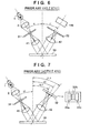
- Fig. 6 shows a specular gloss measuring method defined in JIS Z 8741.
- a light beam from a light source 1 is roughly condensed by a lens 2 to be condensed on a rectangular light source slit 31, which is set to have an aperture angle defined by the standard, and the light source slit 31 forms a secondary light source having the defined aperture angle.
- a light beam from the light source slit 31 is converted into a nearly parallel light beam by a lens 41, and a surface 10 is irradiated with the nearly parallel light beam.
- Light reflected by the surface 10 has a unique reflection pattern depending on a state of the surface 10, and is condensed again by a lens 42, thus forming an image of the light source slit 31 on a light-receiving slit 32.
- Light which has passed through the light-receiving slit 32, enters a light-receiving element 100, and is output as a photoelectric signal from the light-receiving element 100.
- a specular gloss measuring apparatus shown in Fig. 6 calculates a glossiness of the surface 10 using a relative intensity between the amount of light reflected by the surface 10 and an amount of light reflected by a reference surface, which amount is measured in advance.
- the specular gloss measuring apparatus shown in Fig. 6 can define brightness of reflection of a light source, but does not define a blurred degree of reflection of a light source, and cannot perfectly express the state of the surface 10.
- Fig. 7 shows the arrangement of an apparatus for measuring a haze defined by ASTM E 430.
- a light beam from a light source 1 is roughly condensed by a lens 2 to be condensed on a light source slit 31, which is set to have an aperture angle defined by the standard, and the light source slit 31 forms a secondary light source having the defined aperture angle.
- a light beam from the light source slit 31 is converted into a nearly parallel light beam by a lens 41, and a surface 10 is irradiated with the nearly parallel light beam.
- Light reflected by the surface 10 has a unique reflection pattern depending on a state of the surface 10, and is condensed again by a lens 42, thus forming an image of the light source slit 31 on a light-receiving slit 33.
- Light, which has passed through the light-receiving slit 33 enters a light-receiving element, and is output as a photoelectric signal.
- the light-receiving slit 33 includes three slits 33a, 33b, and 33c, which are set at 18.1°, 20°, and 21.9° with respect to a perpendicular to the surface 10.
- the slit 33b is used to measure a specular gloss
- the slits 33a and 33c are used to measure a haze.
- the haze is an index indicating a degree of image unclearness.
- an angle difference from specular reflected light of the slits 33a and 33c is small, a state of the surface 10 suitable for measurement of a haze is limited.
- a reflection image exhibits unclearness beyond recognition, it is difficult to calculate a haze from the measurement result of the measuring apparatus shown in Fig. 7 .
- a distinctness-of-image gloss is measured using an apparatus having the same arrangement as that shown in Fig. 7 except for dimensions of the slits and a value calculation formula. More specifically, angles of the slits 33a, 33b, and 33c with respect to the perpendicular to the surface 10 are 19.7°, 20°, and 20.3°, and slit sizes are different. Like in measurement of a haze and the like, it is difficult for the surface 10 whose reflection image exhibits unclearness beyond recognition to calculate a distinctness-of-image gloss.
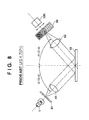
- Fig. 8 shows the arrangement of an apparatus used in an image clarity test method defined by JIS K 7374.
- a light beam from a light source 1 passes through a slit 31 and enters a lens 41 to be converted into parallel light, with which a surface 10 is irradiated. Reflected light by the surface 10 has a unique reflection pattern depending on a state of the surface 10, and is condensed again by a lens 42, thus forming an image of the light source slit 31 on a comb-tooth slit 50.
- the comb-tooth slit 50 is configured by five types of slits having different pitches.
- Contrast values are acquired by calculating maximum and minimum transmitted light amounts upon moving the comb-tooth slit 50 in a slit array direction, thus expressing the state of the surface 10 by five contrast values. Since the image clarity measuring method evaluates the clearness of a reflection image using contrast values, the brightness of the reflection image cannot be discussed.
- Japanese Patent Laid-Open No. 2008-256454 describes an apparatus and method for measuring a specular gloss of a surface
- Japanese Patent Laid-Open No. 2007-24655 describes an apparatus and method for measuring an image clarity of a surface.
- the measuring apparatuses defined by the respective standards have respective features, and measure different target reflection characteristics of a surface.
- Japanese Patent Laid-Open Nos. 2008-256454 and 2007-24655 disclose the apparatuses and methods for measuring reflection characteristics of a surface.
- these apparatuses and methods can only measure limited reflection characteristics of the surface. Therefore, the user in need of various reflection characteristics of a surface, has to prepare for measuring apparatuses of a plurality of methods, and has to selectively use them depending on the situation. For this reason, the user requires cost for purchasing a plurality of apparatuses, and a place for housing the plurality of apparatuses, thus imposing a load on the user.
- the present invention provides, for example, a technique which enables a single measuring apparatus to measure a plurality of types of reflection characteristics of a surface.
- the present invention provides a measuring apparatus as specified in any of accompanying claims 1 to 13.
- Fig. 1 shows a schematic arrangement of a measuring apparatus for measuring a reflection characteristic of a surface according to the first embodiment.
- An illumination device from a light source 1 to a lens 41 and a light-receiving device from a lens 42 to a two-dimensional light-receiving element (detector) 100 are disposed to respectively have angles ⁇ and ⁇ ' with respect to a perpendicular to a surface 10.
- the incident angle ⁇ and reflection angle ⁇ ' are set for each standard to be compliant with that standard which defines a reflection characteristic of the surface 10.
- the incident angle ⁇ and light-receiving angle ⁇ ' are set at any of 20°, 45°, 60°, and 85°.
- the incident angle ⁇ and reflection angle ⁇ ' are set at 20°.
- the incident angle ⁇ and reflection angle ⁇ ' are set at any of 45° and 60°.
- the incident angle ⁇ and reflection angle ⁇ ' are set at 20°.
- a light beam emitted from the light source 1 is condensed on a stop 31 having a circular aperture of ⁇ 1mm by a lens 2.
- an image of the light source 1 is temporarily formed as a circular secondary light source (surface light source) of ⁇ 1mm.
- a light beam emitted from the stop 31 becomes a diverging light beam again, and is converted into parallel light by the lens 41, thus illuminating the surface 10.
- Reflected light from the surface 10 has a unique reflection pattern depending on the reflection characteristic of the surface 10, and is received by a light-receiving surface of the two-dimensional light-receiving element 100.
- the two-dimensional light-receiving element 100 detects an intensity distribution of light formed on the light-receiving surface by the reflected light form the surface 10, and outputs first data to a processor 110. More specifically, the first data is a reflection pattern like a BRDF 1 with which an intensity changes according to an angle.
- the BRDF Bidirectional Reflectance Distribution Function
- a BRDF at a certain point on an object surface depends on two directions, that is, incident and reflection directions, and is defined as a ratio of an intensity of reflected light in an observation direction to that of incident light from an illumination direction.
- a signal received by the two-dimensional light-receiving element 100 can express a reflection characteristic unique to the surface 10 by trimming an output along an AA section on the two-dimensional light-receiving element 100.
- the intensity distribution of reflected light received by the two-dimensional light-receiving element 100 is trimmed along the AA section to cope with calculations of the respective standards which define the reflection characteristics.
- an anisotropy of the reflection characteristic of the surface 10 can also be measured.
- the reflection pattern BRDF 1 received by the two-dimensional light-receiving element 100 is obtained by combining a BRDF 1A by specular reflected light and a BRDF 1B by diffuse reflected light, as shown in Fig. 2 .
- the specular reflected light is also called surface reflected light
- the diffuse reflected light is also called scattered light.
- the BRDF 1B by diffuse reflected light corresponds to so-called a background color and brightness of the surface 10, and seems to have equal brightness independently of a visual line angle, the brightness is expressed by a model which is proportional to COS ⁇ with respect to a visual line angle ⁇ , and is called Lambert scattering.
- the BRDF 1A by specular reflected light corresponds to a state of reflection of the light source 1, is normally modeled by a Gaussian distribution, and is defined by a spread degree and intensity of the distribution as parameters.
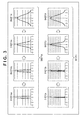
- the light intensity distribution BRDF 1A by specular reflected light when the circular aperture is used changes from a BRDF 1Aa to a BRDF 1Ad during processes in which the surface 10 transits from a specular surface to a scattering surface, as shown in Fig. 3 .
- the surface 10 is a specular surface
- a rectangular BRDF 1Aa with a sharp edge is output.
- the rectangular shape is broken, and a nearly Gaussian distribution like a BRDF 1Ad is finally output.
- BRDFs 1Aa to 1Ad surfaces 10 which exhibit reflection patterns of BRDFs 1Aa to 1Ad by specular reflected light when the surface 10 is irradiated with light using the stop 31 having the circular aperture.
- BRDFs 2 by specular reflected light obtained by the two-dimensional light-receiving element 100 when a point light source (for example, a light source of ⁇ 10 ⁇ m) is disposed at one of a plurality of positions in a plane of the stop 31 and the surfaces 10a to 10d are illuminated with light coming from that light source will be respectively referred to as BRDFs 2a to 2d.
- the BRDFs 2a to 2d are simple Gaussian distribution patterns in which only a spread degree and intensity are changed during transition processes from specular surfaces to scattering surfaces of the surfaces 10a to 10d.
- the BRDFs 2a to 2d can be estimated from addition calculations under the assumption that the circular aperture of the stop 31 is a set of point light sources.
- the BRDFs 2a to 2d can be calculated via actual measurements by arranging a point light source at each of the plurality of positions in the plane of the stop 31.
- information indicating the relationship between the BRDFs 1Aa to 1Ad and the BRDFs 2a to 2d is acquired in advance by calculations or actual measurements, and is stored in a memory 120 of the measuring apparatus.
- a size ⁇ of a point light source is set to fall within a range of several ⁇ m to several ten ⁇ m, and a blurred pattern on the two-dimensional light-receiving element 100 is modeled by being approximated to a Gaussian distribution.
- a blurred image of the circular aperture on the two-dimensional light-receiving element 100 can be assumed to be a set of blurred images of the point light sources.
- Sum totals of light intensities obtained from the respective point light sources as many as the numbers of point light sources on a plane coordinate system on the two-dimensional light-receiving element 100 are equal to the BRDFs 1Aa to 1Ad.
- the BRDFs 2a to 2d can be calculated (back-calculated) from actually measured values of the BRDFs 1Aa to 1Ad.
- the BRDF 1A by specular reflected light when the stop 31 having the circular aperture is used and the reflection pattern BRDF 2 of a point light source can be associated with each other using, for example, a half width and peak ratio of the reflection pattern. Also, since the half width of the reflection pattern is not monotonically increased near specular reflection during blurring processes of an image, the BRDF 1A may be associated with the BRDF 2 using a width other than the half width, for example, a 1/3 width of a peak. The width of the peak used in association with the BRDF 2 may be other widths such as a 1/4 width in addition to the 1/3 width.
- the processor 110 can calculate the reflection pattern BRDF 2 of the point light source from the BRDF 1A.
- the obtained light amount is only about 1/10000 of that obtained when the stop 31 having the circular aperture is used. For this reason, it becomes difficult to precisely measure reflection profiles, or an accumulation time of the two-dimensional light-receiving element 100 has to be prolonged, resulting in a low throughput. Therefore, it is very effective to dispose the stop 31 having the circular aperture of ⁇ 1mm or more, and to calculate the reflection pattern BRDF 2 of the point light source by calculations in terms of signal quality.
- the processor 110 divides the BRDF 1 into the BRDF 1A by specular reflected light and the BRDF 1B by diffuse reflected light, and then calculates a correlation between the BRDF 1A and the reflection pattern BRDF 2 by specular reflected light of the point light source.
- the processor 110 may estimate, based on the BRDF 1, data of the light intensity distribution formed on the light-receiving surface by reflected light when a point light source is disposed at one of a plurality of positions of the circular aperture of the stop 31.
- the processor 110 can calculate the BRDF 2 (second data) by specular reflected light and a BRDF 3 (third data) by diffuse reflected light by dividing the estimated data.
- the processor 110 can calculate the BRDF 3 based on the BRDF 1B by diffuse reflected light and a ratio between the size of the point light source and the circular aperture of the stop 31.
- the BRDF 1B by diffuse reflected light will be described below.
- diffuse reflected light can be modeled by being approximated to Lambert scattering.
- the Lambert scattering defines that a reflected light amount ratio to an angle ⁇ is COS ⁇ based on the fact that the brightness of object on a perfectly diffusing surface (perfect diffuse surface or Lambertian surface) is constant independently of a visual line.
- the BRDF 3 based on the BRDF 1B by diffuse reflected light can be estimated by giving parameters of the diffuse reflectance. Since levels of specular reflected light and diffuse reflected light to be mixed are determined by an area of the light source 1, the diffuse reflectance and the area of the light source 1 can be used in calculations to be described later when they are stored in the memory 120.
- a measuring condition of a settable reflection characteristic includes a shape and size of an arbitrary light source, an arbitrary evaluation region on the light-receiving surface, an incident angle of parallel light, and the like.
- an aperture on the light source side is a rectangle having a width of 0.75° and a length of 2.5°, which are defined by an aperture angle.
- F x COS ⁇ a focal length of the lens 41 and an aperture angle ⁇ . Therefore, if the focal length is 50mm, it can be calculated that a rectangular slit having a width of 0.65mm and a length of 2.18mm is required as the aperture on the light source side.
- a reflection pattern by specular reflected light on the two-dimensional light-receiving element 100 when this rectangular slit is used can be calculated by the processor 110 by adding light amounts on a two-dimensional space to have the rectangular slit of the width of 0.65mm and the length of 2.18mm as a set of point light sources of ⁇ 10 ⁇ m.
- a calculated reflected light pattern on the two-dimensional light-receiving element 100 when the apparatus arrangement of the specular gloss measuring method is adopted can be obtained by the measuring apparatus of the first embodiment.
- a light amount, which enters a light-receiving side area having a width of 1.8° and a length of 3.6°, which are defined by an aperture angle has to be calculated.
- that light amount can be easily calculated from the calculated reflected light pattern on the two-dimensional light-receiving element 100.
- a light irradiation direction in the measuring apparatus is configured to be changed to 20°, 45°, 60°, and 85° like in a conventionally manufactured specular gloss measuring apparatus
- evaluation values specified in various standards in association with a specular gloss, haze, image clarity, and distinctness-of-image gloss can be acquired by a single measuring apparatus.
- the measuring apparatus of the first embodiment can acquire various reflection characteristics of the surface 10, the user need not selectively use a plurality of apparatuses depending on types of reflection characteristics. Also, since the measuring apparatus of the first embodiment uses, as the light source 1, a light source having a certain size in place of a point light source, it is effective in terms of S/N, thus allowing measurements within a short period of time.
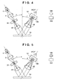
- Fig. 4 shows a schematic arrangement of a measuring apparatus according to the second embodiment.
- a stop 31 has a rectangular slit in place of a circular aperture.
- the rectangular slit of the stop 31 has an aperture angle of 0.75° in a widthwise direction and that of 2.5° in a lengthwise direction, which are defined in the standard required to measure a specular gloss.
- a specular gloss which matches the standard of a specular gloss measuring method can be easily acquired.
- a haze measurement since the aperture angle on the light source side, which is designated by the standard, is the same, a haze can be easily acquired.
- a reflection pattern BRDF 2 of a point light source can be calculated or associated by advanced measurements from a BRDF 1A by specular reflected light upon trimming along an AA section of the two-dimensional light-receiving element 100. Therefore, even when the measuring apparatus of the second embodiment is used, an image clarity can be measured.
- the measuring apparatus of the second embodiment requires a smaller calculation volume than that of the first embodiment, and is further effective in that the apparatus arrangement perfectly matches the standard upon measuring a specular gloss and haze.
- the measuring apparatus of the second embodiment can cope with measurements in only one direction.
- a one-dimensional light-receiving element may be disposed in a direction of AA in place of the two-dimensional light-receiving element 100.
- a load on signal processing can be reduced.
- Fig. 5 shows a schematic arrangement of a measuring apparatus according to the third embodiment.
- a stop 31 has a hexagonal aperture in place of a circular aperture or rectangular slit.
- reflection patterns in three directions perpendicular to three pairs of sides of a hexagon can be measured.
- a specular gloss, haze, and image clarity can be measured.
- the measuring apparatus of the third embodiment can measure reflection patterns in two directions different from an AA section, in addition to measurements that match the standards it can also make determination when a reflection pattern has an anisotropy.
- the stop 31 has a hexagonal aperture, but it may have an n-sided polygonal aperture other than the hexagonal aperture.
- the n-sided polygon is desirably an even-sided polygon (especially, a regular even-sided polygon) in terms of symmetry.
Landscapes
- Physics & Mathematics (AREA)
- Health & Medical Sciences (AREA)
- Life Sciences & Earth Sciences (AREA)
- Chemical & Material Sciences (AREA)
- Analytical Chemistry (AREA)
- Biochemistry (AREA)
- General Health & Medical Sciences (AREA)
- General Physics & Mathematics (AREA)
- Immunology (AREA)
- Pathology (AREA)
- Investigating Or Analysing Materials By Optical Means (AREA)
Abstract
Description
- The present invention relates to a measuring apparatus for measuring a reflection characteristic of a surface.
- Conventionally, it is an important proposition to evaluate a printed product, a painted surface, and an exterior of a product, and JIS and ISO set standards for measuring a reflection characteristic of an object surface (surface) such as gloss. For example, as standards for measuring a specular gloss, JIS Z 8741 and the like are set. As standards for measuring a haze which represents a degree of image unclearness (dullness of a sample surface), ISO13803, ASTM E 430, and the like are set. As standards for measuring distinctness-of-image gloss associated with gloss, ASTM E 430, ASTM D 5767, and the like are set. As standards for measuring an image clarity (image clearness), JIS K 7374, JIS H 8686, and the like are set.
- In respective standards, since there are surfaces suitable and unsuitable for measurement, the user has to select an optimal standard from the aforementioned standards depending on the situation, so as to measure the reflection characteristic.
Fig. 6 shows a specular gloss measuring method defined inJIS Z 8741. A light beam from alight source 1 is roughly condensed by alens 2 to be condensed on a rectangularlight source slit 31, which is set to have an aperture angle defined by the standard, and the light source slit 31 forms a secondary light source having the defined aperture angle. A light beam from thelight source slit 31 is converted into a nearly parallel light beam by alens 41, and asurface 10 is irradiated with the nearly parallel light beam. Light reflected by thesurface 10 has a unique reflection pattern depending on a state of thesurface 10, and is condensed again by alens 42, thus forming an image of thelight source slit 31 on a light-receivingslit 32. Light, which has passed through the light-receivingslit 32, enters a light-receivingelement 100, and is output as a photoelectric signal from the light-receivingelement 100. A specular gloss measuring apparatus shown inFig. 6 calculates a glossiness of thesurface 10 using a relative intensity between the amount of light reflected by thesurface 10 and an amount of light reflected by a reference surface, which amount is measured in advance. The specular gloss measuring apparatus shown inFig. 6 can define brightness of reflection of a light source, but does not define a blurred degree of reflection of a light source, and cannot perfectly express the state of thesurface 10. -
Fig. 7 shows the arrangement of an apparatus for measuring a haze defined by ASTM E 430. A light beam from alight source 1 is roughly condensed by alens 2 to be condensed on alight source slit 31, which is set to have an aperture angle defined by the standard, and the light source slit 31 forms a secondary light source having the defined aperture angle. A light beam from thelight source slit 31 is converted into a nearly parallel light beam by alens 41, and asurface 10 is irradiated with the nearly parallel light beam. Light reflected by thesurface 10 has a unique reflection pattern depending on a state of thesurface 10, and is condensed again by alens 42, thus forming an image of thelight source slit 31 on a light-receiving slit 33. Light, which has passed through the light-receiving slit 33, enters a light-receiving element, and is output as a photoelectric signal. The light-receiving slit 33 includes threeslits surface 10. Theslit 33b is used to measure a specular gloss, and theslits slits surface 10 suitable for measurement of a haze is limited. When a reflection image exhibits unclearness beyond recognition, it is difficult to calculate a haze from the measurement result of the measuring apparatus shown inFig. 7 . - A distinctness-of-image gloss is measured using an apparatus having the same arrangement as that shown in
Fig. 7 except for dimensions of the slits and a value calculation formula. More specifically, angles of theslits surface 10 are 19.7°, 20°, and 20.3°, and slit sizes are different. Like in measurement of a haze and the like, it is difficult for thesurface 10 whose reflection image exhibits unclearness beyond recognition to calculate a distinctness-of-image gloss. -
Fig. 8 shows the arrangement of an apparatus used in an image clarity test method defined by JIS K 7374. A light beam from alight source 1 passes through aslit 31 and enters alens 41 to be converted into parallel light, with which asurface 10 is irradiated. Reflected light by thesurface 10 has a unique reflection pattern depending on a state of thesurface 10, and is condensed again by alens 42, thus forming an image of thelight source slit 31 on a comb-tooth slit 50. The comb-tooth slit 50 is configured by five types of slits having different pitches. Contrast values are acquired by calculating maximum and minimum transmitted light amounts upon moving the comb-tooth slit 50 in a slit array direction, thus expressing the state of thesurface 10 by five contrast values. Since the image clarity measuring method evaluates the clearness of a reflection image using contrast values, the brightness of the reflection image cannot be discussed. - Japanese Patent Laid-Open No.
2008-256454 2007-24655 - As described above, the measuring apparatuses defined by the respective standards have respective features, and measure different target reflection characteristics of a surface. Also, Japanese Patent Laid-Open Nos.
2008-256454 2007-24655 - The present invention provides, for example, a technique which enables a single measuring apparatus to measure a plurality of types of reflection characteristics of a surface.
- The present invention provides a measuring apparatus as specified in any of accompanying
claims 1 to 13. - Further features of the present invention will become apparent from the following description of embodiments with reference to the attached drawings.
-
-
Fig. 1 is a schematic view showing the arrangement of a measuring apparatus according to the first embodiment; -
Fig. 2 is a graph showing an intensity distribution when specular reflected light and diffuse reflected light are combined; -
Fig. 3 shows graphs of a transition of intensity distributions of specular reflected light in case of a circular aperture, and that of intensity distributions of specular reflected light in case of a point light source; -
Fig. 4 is a schematic view showing the arrangement of a measuring apparatus according to the second embodiment; -
Fig. 5 is a schematic view showing the arrangement of a measuring apparatus according to the third embodiment; -
Fig. 6 is a view showing the arrangement of a specular gloss measuring apparatus designated by JISZ 8741; -
Fig. 7 is a view showing the arrangement of a haze measuring apparatus designated by ASTM E 430; and -
Fig. 8 is a view showing the arrangement of an image clarity measuring apparatus designated by JIS K 7374. - Embodiments of the present invention will be described in detail hereinafter with reference to the accompanying drawings.
-
Fig. 1 shows a schematic arrangement of a measuring apparatus for measuring a reflection characteristic of a surface according to the first embodiment. An illumination device from alight source 1 to alens 41 and a light-receiving device from alens 42 to a two-dimensional light-receiving element (detector) 100 are disposed to respectively have angles θ and θ' with respect to a perpendicular to asurface 10. The incident angle θ and reflection angle θ' are set for each standard to be compliant with that standard which defines a reflection characteristic of thesurface 10. When a reflection characteristic is a specular gloss, the incident angle θ and light-receiving angle θ' are set at any of 20°, 45°, 60°, and 85°. When a reflection characteristic is a haze, the incident angle θ and reflection angle θ' are set at 20°. When a reflection characteristic is an image clarity, the incident angle θ and reflection angle θ' are set at any of 45° and 60°. When a reflection characteristic is a distinctness-of-image gloss, the incident angle θ and reflection angle θ' are set at 20°. - A light beam emitted from the
light source 1 is condensed on astop 31 having a circular aperture of φ1mm by alens 2. On thestop 31, an image of thelight source 1 is temporarily formed as a circular secondary light source (surface light source) of φ1mm. A light beam emitted from thestop 31 becomes a diverging light beam again, and is converted into parallel light by thelens 41, thus illuminating thesurface 10. Reflected light from thesurface 10 has a unique reflection pattern depending on the reflection characteristic of thesurface 10, and is received by a light-receiving surface of the two-dimensional light-receivingelement 100. The two-dimensional light-receivingelement 100 detects an intensity distribution of light formed on the light-receiving surface by the reflected light form thesurface 10, and outputs first data to aprocessor 110. More specifically, the first data is a reflection pattern like aBRDF 1 with which an intensity changes according to an angle. Note that the BRDF (Bidirectional Reflectance Distribution Function) is a function which expresses a reflectance distribution of thesurface 10, and represents a ratio of reflected light luminance to incident light illuminance. More strictly, a BRDF at a certain point on an object surface depends on two directions, that is, incident and reflection directions, and is defined as a ratio of an intensity of reflected light in an observation direction to that of incident light from an illumination direction. A signal received by the two-dimensional light-receivingelement 100 can express a reflection characteristic unique to thesurface 10 by trimming an output along an AA section on the two-dimensional light-receivingelement 100. - The intensity distribution of reflected light received by the two-dimensional light-receiving
element 100 is trimmed along the AA section to cope with calculations of the respective standards which define the reflection characteristics. When the intensity distribution of reflected light is trimmed along another section in addition to the AA section, an anisotropy of the reflection characteristic of thesurface 10 can also be measured. Thereflection pattern BRDF 1 received by the two-dimensional light-receivingelement 100 is obtained by combining a BRDF 1A by specular reflected light and a BRDF 1B by diffuse reflected light, as shown inFig. 2 . The specular reflected light is also called surface reflected light, and the diffuse reflected light is also called scattered light. Since the BRDF 1B by diffuse reflected light corresponds to so-called a background color and brightness of thesurface 10, and seems to have equal brightness independently of a visual line angle, the brightness is expressed by a model which is proportional to COSθ with respect to a visual line angle θ, and is called Lambert scattering. The BRDF 1A by specular reflected light corresponds to a state of reflection of thelight source 1, is normally modeled by a Gaussian distribution, and is defined by a spread degree and intensity of the distribution as parameters. - In this case, attention will be focused on the BRDF 1A based on the specular reflected light obtained by the two-dimensional light-receiving
element 100 using thestop 31 having the circular aperture. The light intensity distribution BRDF 1A by specular reflected light when the circular aperture is used changes from a BRDF 1Aa to a BRDF 1Ad during processes in which thesurface 10 transits from a specular surface to a scattering surface, as shown inFig. 3 . When thesurface 10 is a specular surface, since the circular aperture of thestop 31 is projected intact on the two-dimensional light-receivingelement 100, a rectangular BRDF 1Aa with a sharp edge is output. During processes in which thesurface 10 becomes closer to a diffusing surface, the rectangular shape is broken, and a nearly Gaussian distribution like a BRDF 1Ad is finally output. - Assume that four
surfaces 10 which exhibit reflection patterns of BRDFs 1Aa to 1Ad by specular reflected light when thesurface 10 is irradiated with light using thestop 31 having the circular aperture will be respectively referred to as surfaces 10a to 10d. Assume thatBRDFs 2 by specular reflected light obtained by the two-dimensional light-receivingelement 100 when a point light source (for example, a light source of φ10µm) is disposed at one of a plurality of positions in a plane of thestop 31 and the surfaces 10a to 10d are illuminated with light coming from that light source will be respectively referred to as BRDFs 2a to 2d. The BRDFs 2a to 2d are simple Gaussian distribution patterns in which only a spread degree and intensity are changed during transition processes from specular surfaces to scattering surfaces of the surfaces 10a to 10d. The BRDFs 2a to 2d can be estimated from addition calculations under the assumption that the circular aperture of thestop 31 is a set of point light sources. Alternatively, the BRDFs 2a to 2d can be calculated via actual measurements by arranging a point light source at each of the plurality of positions in the plane of thestop 31. In the first embodiment, information indicating the relationship between the BRDFs 1Aa to 1Ad and the BRDFs 2a to 2d is acquired in advance by calculations or actual measurements, and is stored in amemory 120 of the measuring apparatus. - When the BRDFs 2a to 2d are to be calculated, for example, a size φ of a point light source is set to fall within a range of several µm to several ten µm, and a blurred pattern on the two-dimensional light-receiving
element 100 is modeled by being approximated to a Gaussian distribution. Assuming that the circular aperture of thestop 31 is a set of point light sources, a blurred image of the circular aperture on the two-dimensional light-receivingelement 100 can be assumed to be a set of blurred images of the point light sources. Sum totals of light intensities obtained from the respective point light sources as many as the numbers of point light sources on a plane coordinate system on the two-dimensional light-receivingelement 100 are equal to the BRDFs 1Aa to 1Ad. Based on the aforementioned principle, the BRDFs 2a to 2d can be calculated (back-calculated) from actually measured values of the BRDFs 1Aa to 1Ad. - The BRDF 1A by specular reflected light when the
stop 31 having the circular aperture is used and thereflection pattern BRDF 2 of a point light source can be associated with each other using, for example, a half width and peak ratio of the reflection pattern. Also, since the half width of the reflection pattern is not monotonically increased near specular reflection during blurring processes of an image, the BRDF 1A may be associated with theBRDF 2 using a width other than the half width, for example, a 1/3 width of a peak. The width of the peak used in association with theBRDF 2 may be other widths such as a 1/4 width in addition to the 1/3 width. However, when the width of the peak used in association with theBRDF 2 falls below a 1/5 width, a boundary between specular reflected light and diffuse reflected light (scattered light) becomes unspecific, and an inclination of a Gaussian distribution waveform becomes moderate, thus readily causing errors. Alternatively, a correlation of maximum values (peaks of differential waveforms) of inclination values of profiles of the BRDFs 2a to 2d and BRDFs 1Aa to 1Ad or that of distances between maximum values of inclinations of profiles may be calculated, or a correlation may be calculated by combining them. With the aforementioned method, theprocessor 110 can calculate thereflection pattern BRDF 2 of the point light source from the BRDF 1A. - For example, assume that a pinhole of φ10µm is actually disposed as a point light source at a position of the circular aperture of the
stop 31. Then, the obtained light amount is only about 1/10000 of that obtained when thestop 31 having the circular aperture is used. For this reason, it becomes difficult to precisely measure reflection profiles, or an accumulation time of the two-dimensional light-receivingelement 100 has to be prolonged, resulting in a low throughput. Therefore, it is very effective to dispose thestop 31 having the circular aperture of φ1mm or more, and to calculate thereflection pattern BRDF 2 of the point light source by calculations in terms of signal quality. In the first embodiment, theprocessor 110 divides theBRDF 1 into the BRDF 1A by specular reflected light and the BRDF 1B by diffuse reflected light, and then calculates a correlation between the BRDF 1A and thereflection pattern BRDF 2 by specular reflected light of the point light source. - However, the
processor 110 may estimate, based on theBRDF 1, data of the light intensity distribution formed on the light-receiving surface by reflected light when a point light source is disposed at one of a plurality of positions of the circular aperture of thestop 31. Theprocessor 110 can calculate the BRDF 2 (second data) by specular reflected light and a BRDF 3 (third data) by diffuse reflected light by dividing the estimated data. In this case, theprocessor 110 can calculate theBRDF 3 based on the BRDF 1B by diffuse reflected light and a ratio between the size of the point light source and the circular aperture of thestop 31. - The BRDF 1B by diffuse reflected light will be described below. As is known, diffuse reflected light can be modeled by being approximated to Lambert scattering. The Lambert scattering defines that a reflected light amount ratio to an angle θ is COSθ based on the fact that the brightness of object on a perfectly diffusing surface (perfect diffuse surface or Lambertian surface) is constant independently of a visual line. When a BRDF based on reflected light generated by a reference surface having a given diffuse reflectance (diffuse reflected light/incident light) is measured in advance using this measuring apparatus, the
BRDF 3 based on the BRDF 1B by diffuse reflected light can be estimated by giving parameters of the diffuse reflectance. Since levels of specular reflected light and diffuse reflected light to be mixed are determined by an area of thelight source 1, the diffuse reflectance and the area of thelight source 1 can be used in calculations to be described later when they are stored in thememory 120. - A process for calculating standard values of various reflection characteristics defined by arbitrary measuring conditions from the
reflection pattern BRDF 2 of the point light source derived in the above processes will be described below. A measuring condition of a settable reflection characteristic includes a shape and size of an arbitrary light source, an arbitrary evaluation region on the light-receiving surface, an incident angle of parallel light, and the like. - For example, assume that a glossimeter described in
JIS Z 8741 of a specular gloss is configured. Theprocessor 110 calculated theBRDF 2 by specular reflected light in case of φ10µm in the above processes. When a specular gloss is to be measured at an incident angle of 20°, an aperture on the light source side is a rectangle having a width of 0.75° and a length of 2.5°, which are defined by an aperture angle. Using a focal length F of thelens 41 and an aperture angle β, a size of the aperture on the light source side can be calculated by F x COSβ. Therefore, if the focal length is 50mm, it can be calculated that a rectangular slit having a width of 0.65mm and a length of 2.18mm is required as the aperture on the light source side. - A reflection pattern by specular reflected light on the two-dimensional light-receiving
element 100 when this rectangular slit is used can be calculated by theprocessor 110 by adding light amounts on a two-dimensional space to have the rectangular slit of the width of 0.65mm and the length of 2.18mm as a set of point light sources of φ10µm. The light intensity distribution by diffuse reflected light when this rectangular slit is used can be calculated by multiplying the divided BRDF 1B by an area ratio 0.65 x 2.18 ÷ (π x 0.52) = 1.8 of the rectangular slit with respect to the circular aperture. In this manner, a calculated reflected light pattern on the two-dimensional light-receivingelement 100 when the apparatus arrangement of the specular gloss measuring method is adopted can be obtained by the measuring apparatus of the first embodiment. In order to output a standard value ofJIS Z 8741, a light amount, which enters a light-receiving side area having a width of 1.8° and a length of 3.6°, which are defined by an aperture angle, has to be calculated. However, that light amount can be easily calculated from the calculated reflected light pattern on the two-dimensional light-receivingelement 100. - The measurement of the specular gloss has been explained. However, as for haze and distinctness-of-image gloss measurements, similar calculations can be made. As for an image clarity measurement, a comb-tooth slit defined in the
JIS K 7374 standard is assumed as a light-receiving area assumed on the two-dimensional light-receivingelement 100. An image clarity can be calculated from maximum and minimum transmitted light amounts during a moving process of the assumed light-receiving area by one slit pitch. When a light irradiation direction in the measuring apparatus is configured to be changed to 20°, 45°, 60°, and 85° like in a conventionally manufactured specular gloss measuring apparatus, evaluation values specified in various standards in association with a specular gloss, haze, image clarity, and distinctness-of-image gloss can be acquired by a single measuring apparatus. - As described above, since the measuring apparatus of the first embodiment can acquire various reflection characteristics of the
surface 10, the user need not selectively use a plurality of apparatuses depending on types of reflection characteristics. Also, since the measuring apparatus of the first embodiment uses, as thelight source 1, a light source having a certain size in place of a point light source, it is effective in terms of S/N, thus allowing measurements within a short period of time. -
Fig. 4 shows a schematic arrangement of a measuring apparatus according to the second embodiment. Unlike in the first embodiment, astop 31 has a rectangular slit in place of a circular aperture. The rectangular slit of thestop 31 has an aperture angle of 0.75° in a widthwise direction and that of 2.5° in a lengthwise direction, which are defined in the standard required to measure a specular gloss. For this reason, by adding outputs of an element of an aperture angle on the light-receiving device side, which is designated by the standard, on a two-dimensional light-receivingelement 100, a specular gloss which matches the standard of a specular gloss measuring method can be easily acquired. Likewise, as for a haze measurement, since the aperture angle on the light source side, which is designated by the standard, is the same, a haze can be easily acquired. - On the other hand, in the same manner as in the process described using
Fig. 3 of the first embodiment, areflection pattern BRDF 2 of a point light source can be calculated or associated by advanced measurements from a BRDF 1A by specular reflected light upon trimming along an AA section of the two-dimensional light-receivingelement 100. Therefore, even when the measuring apparatus of the second embodiment is used, an image clarity can be measured. The measuring apparatus of the second embodiment requires a smaller calculation volume than that of the first embodiment, and is further effective in that the apparatus arrangement perfectly matches the standard upon measuring a specular gloss and haze. The measuring apparatus of the second embodiment can cope with measurements in only one direction. Hence, a one-dimensional light-receiving element may be disposed in a direction of AA in place of the two-dimensional light-receivingelement 100. In this case, since a data amount is greatly reduced, a load on signal processing can be reduced. -
Fig. 5 shows a schematic arrangement of a measuring apparatus according to the third embodiment. Unlike in the first and second embodiments, astop 31 has a hexagonal aperture in place of a circular aperture or rectangular slit. In this case, reflection patterns in three directions perpendicular to three pairs of sides of a hexagon can be measured. Like in the first and second embodiments, a specular gloss, haze, and image clarity can be measured. Since the measuring apparatus of the third embodiment can measure reflection patterns in two directions different from an AA section, in addition to measurements that match the standards it can also make determination when a reflection pattern has an anisotropy. In the third embodiment, thestop 31 has a hexagonal aperture, but it may have an n-sided polygonal aperture other than the hexagonal aperture. The n-sided polygon is desirably an even-sided polygon (especially, a regular even-sided polygon) in terms of symmetry. - While the present invention has been described with reference to embodiments, it is to be understood that the invention is not limited to the disclosed exemplary embodiments. Preferred embodiments are set out in the following statements. The claims follow these statements and are labeled as such.
-
Statement 1. A measuring apparatus for measuring a reflection characteristic of a surface (10), the measuring apparatus including
an illumination device (1, 2, 31, 41) including a surface light source (1) and configured to illuminate the surface with light from the surface light source,
a detector (100) configured to detect a light intensity distribution formed on a light-receiving surface by reflected light from the surface illuminated by said illumination device, and
a processor (110) configured to obtain the reflection characteristic based on first data of the light intensity distribution detected by said detector,
the apparatus characterized in that said processor is configured to estimate, based on the first data, second data of a light intensity distribution formed on the light-receiving surface by specular reflected light from the surface and third data of a light intensity distribution formed on the light-receiving surface by diffuse reflected light from the surface in a case where a point light source is disposed at each position in a light-emitting region of the surface light source, and to estimate, based on the second data and the third data, a light intensity distribution formed on the light-receiving surface by reflected light from the surface in a case where a light source, at least one of a shape and a size of a light-emitting region of which is different from that of the surface light source, is disposed in place of the surface light source. - 2. The apparatus according to
statement 1, characterized in that said processor is configured to obtain, based on the second data and the third data, a light intensity distribution formed on an evaluation area set with respect to the light-receiving surface. - 3. The apparatus according to
statement 2, characterized in that a measuring condition, settable in the apparatus, includes at least one of the shape, the size, and the evaluation area. - 4. The apparatus according to any one of
statements 1 to 3, characterized in that the surface light source is a circular light source, and said detector includes a two-dimensional light-receiving element array. - 5. The apparatus according to any one of
statements 1 to 3, characterized in that the surface light source is a rectangular light source, and said detector includes one of a two-dimensional light-receiving element array and a one-dimensional light-receiving element array. - 6. The apparatus according to any one of
statements 1 to 3, characterized in that the surface light source is an n-sided polygonal light source, and said detector includes a two-dimensional light-receiving element array. - 7. The apparatus according to any one of
statements 1 to 6, characterized in that the reflection characteristic includes at least one of a specular gloss, a haze, a distinctness-of-image gloss, and an image clarity. - 8. The apparatus according to any one of
statements 1 to 7, characterized in that said processor is configured to estimate the second data based on a Gaussian distribution, and to estimate the third data based on Lambert scattering. - 9. The apparatus according to statements 8, characterized in that said processor is configured to estimate the third data based on data of a diffuse reflectance of the surface, and data of a light intensity distribution formed on the light-receiving surface with a reference surface having a known diffuse reflectance as a surface to be measured.
- 10. The apparatus according to any one of
statements 1 to 9, characterized in that said processor is configured to estimate, based on the first data, data of a light intensity distribution formed on the light-receiving surface by reflected light from the surface in a case where a point light source is disposed at each position in a light-emitting region of the surface light source, and to obtain the second data and the third data by dividing the estimated data. - 11. The apparatus according to any one of
statements 1 to 9, characterized in that said processor is configured to divide the first data into data of a specular reflected light intensity distribution and data of a diffuse reflected light intensity distribution, and to estimate the second data and the third data respectively based on the two data obtained by the division. - 12. The apparatus according to statement 11, characterized in that said processor is configured to estimate the third data based on the data of the diffuse reflected light intensity distribution, and a ratio between a size of the point light source and a size of the surface light source.
- 13. The apparatus according to statement 11 or 12, characterized in that said processor is configured to estimate the second data based on information indicating a relation between the specular reflected light intensity distribution and the second data, and the data of the specular reflected light intensity distribution.
Claims (13)
- A measuring apparatus for measuring a reflection characteristic of a surface (10), the measuring apparatus including
an illumination device (1, 2, 31, 41) including a surface light source (1) and configured to illuminate the surface with light from the surface light source,
a detector (100) configured to detect a light intensity distribution formed on a light-receiving surface by reflected light from the surface illuminated by said illumination device, and
a processor (110) configured to obtain the reflection characteristic based on first data of the light intensity distribution detected by said detector,
the apparatus characterized in that said processor is configured to estimate, based on the first data, second data of a light intensity distribution formed on the light-receiving surface by specular reflected light from the surface and third data of a light intensity distribution formed on the light-receiving surface by diffuse reflected light from the surface in a case where a point light source is disposed at each position in a light-emitting region of the surface light source, and to estimate, based on the second data and the third data, a light intensity distribution formed on the light-receiving surface by reflected light from the surface in a case where a light source, at least one of a shape and a size of a light-emitting region of which is different from that of the surface light source, is disposed in place of the surface light source. - The apparatus according to claim 1, characterized in that said processor is configured to obtain, based on the second data and the third data, a light intensity distribution formed on an evaluation area set with respect to the light-receiving surface.
- The apparatus according to claim 2, characterized in that a measuring condition, settable in the apparatus, includes at least one of the shape, the size, and the evaluation area.
- The apparatus according to any one of claims 1 to 3, characterized in that the surface light source is a circular light source, and said detector includes a two-dimensional light-receiving element array.
- The apparatus according to any one of claims 1 to 3, characterized in that the surface light source is a rectangular light source, and said detector includes one of a two-dimensional light-receiving element array and a one-dimensional light-receiving element array.
- The apparatus according to any one of claims 1 to 3, characterized in that the surface light source is an n-sided polygonal light source, and said detector includes a two-dimensional light-receiving element array.
- The apparatus according to any one of claims 1 to 6, characterized in that the reflection characteristic includes at least one of a specular gloss, a haze, a distinctness-of-image gloss, and an image clarity.
- The apparatus according to any one of claims 1 to 7, characterized in that said processor is configured to estimate the second data based on a Gaussian distribution, and to estimate the third data based on Lambert scattering.
- The apparatus according to claim 8, characterized in that said processor is configured to estimate the third data based on data of a diffuse reflectance of the surface, and data of a light intensity distribution formed on the light-receiving surface with a reference surface having a known diffuse reflectance as a surface to be measured.
- The apparatus according to any one of claims 1 to 9, characterized in that said processor is configured to estimate, based on the first data, data of a light intensity distribution formed on the light-receiving surface by reflected light from the surface in a case where a point light source is disposed at each position in a light-emitting region of the surface light source, and to obtain the second data and the third data by dividing the estimated data.
- The apparatus according to any one of claims 1 to 9, characterized in that said processor is configured to divide the first data into data of a specular reflected light intensity distribution and data of a diffuse reflected light intensity distribution, and to estimate the second data and the third data respectively based on the two data obtained by the division.
- The apparatus according to claim 11, characterized in that said processor is configured to estimate the third data based on the data of the diffuse reflected light intensity distribution, and a ratio between a size of the point light source and a size of the surface light source.
- The apparatus according to claim 11 or 12, characterized in that said processor is configured to estimate the second data based on information indicating a relation between the specular reflected light intensity distribution and the second data, and the data of the specular reflected light intensity distribution.
Applications Claiming Priority (1)
| Application Number | Priority Date | Filing Date | Title |
|---|---|---|---|
| JP2012281756A JP6053506B2 (en) | 2012-12-25 | 2012-12-25 | Reflection characteristic measuring device |
Publications (2)
| Publication Number | Publication Date |
|---|---|
| EP2749865A1 true EP2749865A1 (en) | 2014-07-02 |
| EP2749865B1 EP2749865B1 (en) | 2021-02-17 |
Family
ID=50064332
Family Applications (1)
| Application Number | Title | Priority Date | Filing Date |
|---|---|---|---|
| EP13197240.8A Not-in-force EP2749865B1 (en) | 2012-12-25 | 2013-12-13 | Reflection characteristic measuring apparatus |
Country Status (3)
| Country | Link |
|---|---|
| US (2) | US8976361B2 (en) |
| EP (1) | EP2749865B1 (en) |
| JP (1) | JP6053506B2 (en) |
Cited By (2)
| Publication number | Priority date | Publication date | Assignee | Title |
|---|---|---|---|---|
| EP3093650A1 (en) * | 2015-05-11 | 2016-11-16 | Canon Kabushiki Kaisha | Measuring apparatus, measuring method, and program |
| CN110192099A (en) * | 2017-01-13 | 2019-08-30 | 佳能株式会社 | Measuring device, information processing unit, information processing method and program |
Families Citing this family (13)
| Publication number | Priority date | Publication date | Assignee | Title |
|---|---|---|---|---|
| JP2602851B2 (en) | 1987-10-27 | 1997-04-23 | 株式会社東芝 | Horizontal image phase adjustment circuit |
| JP6657794B2 (en) * | 2015-10-30 | 2020-03-04 | 大日本印刷株式会社 | Light diffusivity measuring apparatus and light diffusivity measuring method |
| FR3049709B1 (en) * | 2016-04-05 | 2019-08-30 | Areva Np | METHOD OF DETECTING A DEFECT ON A SURFACE BY MULTIDIRECTIONAL LIGHTING AND ASSOCIATED DEVICE |
| JP6894672B2 (en) | 2016-05-18 | 2021-06-30 | キヤノン株式会社 | Information processing equipment, information processing methods, programs |
| JP6682350B2 (en) * | 2016-05-18 | 2020-04-15 | キヤノン株式会社 | Information processing device, control device, information processing method, control method, and program |
| JP6776004B2 (en) * | 2016-05-26 | 2020-10-28 | キヤノン株式会社 | Image processing equipment, image processing methods and programs |
| DE102016220290A1 (en) * | 2016-10-18 | 2018-04-19 | Robert Bosch Gmbh | Method and apparatus for detecting a direct light reflection beam from an object to a light sensor |
| CN107478612B (en) * | 2017-09-20 | 2023-08-04 | 安费诺(常州)连接系统有限公司 | Sensor and method for detecting dust accumulation of filter |
| JP2019207175A (en) | 2018-05-30 | 2019-12-05 | キヤノン株式会社 | Measurement device |
| MX2021003324A (en) | 2018-09-20 | 2021-05-14 | Ppg Ind Ohio Inc | Thiol-containing composition. |
| US11965782B2 (en) * | 2018-12-04 | 2024-04-23 | Columbia Insurance Company | Adjusted color prescriptions for aqueous coating compositions to correct gloss differences |
| JP7446725B2 (en) * | 2019-06-28 | 2024-03-11 | キヤノン株式会社 | Measuring device, measuring method, and program |
| JP7625980B2 (en) * | 2021-06-08 | 2025-02-04 | コニカミノルタ株式会社 | Image forming system and gloss level detection method |
Citations (2)
| Publication number | Priority date | Publication date | Assignee | Title |
|---|---|---|---|---|
| JP2007024655A (en) | 2005-07-15 | 2007-02-01 | Canon Inc | Method and apparatus for measuring image clarity |
| US20080246969A1 (en) * | 2007-04-03 | 2008-10-09 | Kenji Imura | Apparatus and method for measuring optical property |
Family Cites Families (12)
| Publication number | Priority date | Publication date | Assignee | Title |
|---|---|---|---|---|
| JP2915192B2 (en) * | 1991-11-26 | 1999-07-05 | 川崎製鉄株式会社 | Evaluation method for thin coating metal plate and thin coating metal plate with excellent sharpness of thin coating film |
| JPH08247858A (en) * | 1995-03-07 | 1996-09-27 | Toshiba Corp | Optical temperature distribution sensor and temperature distribution measuring method |
| US6208749B1 (en) * | 1997-02-28 | 2001-03-27 | Electro-Optical Sciences, Inc. | Systems and methods for the multispectral imaging and characterization of skin tissue |
| JP3768052B2 (en) * | 1999-12-14 | 2006-04-19 | 株式会社リコー | Color image processing method, color image processing apparatus, and recording medium therefor |
| JP4073200B2 (en) * | 2001-11-08 | 2008-04-09 | 富士フイルム株式会社 | Image recording method and inkjet printer |
| JP2003302211A (en) * | 2002-04-11 | 2003-10-24 | Canon Inc | Three-dimensional image processing apparatus and method |
| JP3938184B2 (en) * | 2005-03-22 | 2007-06-27 | キヤノン株式会社 | Information processing method and apparatus |
| JP2008145225A (en) * | 2006-12-08 | 2008-06-26 | Konica Minolta Sensing Inc | Optical characteristic measurement method and optical characteristic measuring device |
| JP5202150B2 (en) * | 2008-07-16 | 2013-06-05 | キヤノン株式会社 | Image processing apparatus and method |
| JP2010145198A (en) * | 2008-12-18 | 2010-07-01 | Seiko Epson Corp | Method of calculating image quality, apparatus of inspecting image quality, and program |
| JP5591017B2 (en) * | 2010-08-09 | 2014-09-17 | キヤノン株式会社 | Image processing apparatus and image processing method |
| JP5636885B2 (en) * | 2010-11-08 | 2014-12-10 | 株式会社リコー | Image processing apparatus, image forming apparatus, and image processing system |
-
2012
- 2012-12-25 JP JP2012281756A patent/JP6053506B2/en active Active
-
2013
- 2013-12-13 EP EP13197240.8A patent/EP2749865B1/en not_active Not-in-force
- 2013-12-23 US US14/138,369 patent/US8976361B2/en not_active Expired - Fee Related
-
2015
- 2015-02-04 US US14/613,526 patent/US9528934B2/en not_active Expired - Fee Related
Patent Citations (3)
| Publication number | Priority date | Publication date | Assignee | Title |
|---|---|---|---|---|
| JP2007024655A (en) | 2005-07-15 | 2007-02-01 | Canon Inc | Method and apparatus for measuring image clarity |
| US20080246969A1 (en) * | 2007-04-03 | 2008-10-09 | Kenji Imura | Apparatus and method for measuring optical property |
| JP2008256454A (en) | 2007-04-03 | 2008-10-23 | Konica Minolta Sensing Inc | Optical characteristic measuring device and method |
Non-Patent Citations (1)
| Title |
|---|
| LELOUP F B ET AL: "Design of an instrument for measuring the spectral bidirectional scatter distribution function", APPLIED OPTICS, OPTICAL SOCIETY OF AMERICA, WASHINGTON, DC; US, vol. 47, no. 29, 10 October 2008 (2008-10-10), pages 5454 - 5467, XP001518886, ISSN: 0003-6935, DOI: 10.1364/AO.47.005454 * |
Cited By (8)
| Publication number | Priority date | Publication date | Assignee | Title |
|---|---|---|---|---|
| EP3093650A1 (en) * | 2015-05-11 | 2016-11-16 | Canon Kabushiki Kaisha | Measuring apparatus, measuring method, and program |
| US20160335772A1 (en) * | 2015-05-11 | 2016-11-17 | Canon Kabushiki Kaisha | Measuring apparatus, measuring method, and program |
| KR20160132778A (en) * | 2015-05-11 | 2016-11-21 | 캐논 가부시끼가이샤 | Measuring apparatus, measuring method, and storage medium |
| CN106153579A (en) * | 2015-05-11 | 2016-11-23 | 佳能株式会社 | Measurement apparatus, measuring method and program |
| US10235743B2 (en) * | 2015-05-11 | 2019-03-19 | Canon Kabushiki Kaisha | Measuring apparatus, measuring method, and program |
| CN106153579B (en) * | 2015-05-11 | 2019-07-23 | 佳能株式会社 | Measuring device, measurement method and program |
| CN110192099A (en) * | 2017-01-13 | 2019-08-30 | 佳能株式会社 | Measuring device, information processing unit, information processing method and program |
| EP3570010A4 (en) * | 2017-01-13 | 2020-10-07 | C/o Canon Kabushiki Kaisha | Measuring device, information processing device, information processing method, and program |
Also Published As
| Publication number | Publication date |
|---|---|
| JP6053506B2 (en) | 2016-12-27 |
| US9528934B2 (en) | 2016-12-27 |
| US8976361B2 (en) | 2015-03-10 |
| EP2749865B1 (en) | 2021-02-17 |
| US20140176953A1 (en) | 2014-06-26 |
| US20150153276A1 (en) | 2015-06-04 |
| JP2014126408A (en) | 2014-07-07 |
Similar Documents
| Publication | Publication Date | Title |
|---|---|---|
| EP2749865B1 (en) | Reflection characteristic measuring apparatus | |
| US12366526B2 (en) | Optical test apparatus and optical test method | |
| JP7308823B2 (en) | Particle size distribution measuring device and program for particle size distribution measuring device | |
| US10837903B2 (en) | Information processing apparatus, method of deriving reflection characteristics, program, and reflection characteristic profile | |
| JP2014126408A5 (en) | ||
| JP6542906B2 (en) | Method and apparatus for determining surface data and / or measurement data associated with the surface of an at least partially transparent object | |
| US20180365821A1 (en) | Image processing apparatus, method, and storage medium | |
| US20020113975A1 (en) | Method and measuring arrangement for measuring paper surface | |
| JP7223752B2 (en) | Particle size distribution measuring device and program for particle size distribution measuring device | |
| JP2018515747A5 (en) | ||
| EP3159679A1 (en) | Apparatus and method for measuring haze of sheet materials or other materials using off-axis detector | |
| Inoue et al. | Point spread function of specular reflection and gonio-reflectance distribution | |
| EP2913659B1 (en) | Optical system and apparatus for measuring optical quality of a surface | |
| CN106950182A (en) | A kind of method for differentiating different fresh laser mother matrix microstructures | |
| JP2009520980A (en) | Optical measuring device | |
| US20190331600A1 (en) | Measurement apparatus, information processing apparatus, information processing method, and storage medium | |
| JP7446725B2 (en) | Measuring device, measuring method, and program | |
| JP2010145198A (en) | Method of calculating image quality, apparatus of inspecting image quality, and program | |
| Hertzsch et al. | Microtopographic analysis of turned surfaces by model-based scatterometry | |
| JP7488224B2 (en) | Surface roughness measuring method, surface roughness measuring device, and program | |
| Tominaga et al. | Measurement and modeling of bidirectional characteristics of fluorescent objects | |
| JP2017190957A (en) | Optical measuring device | |
| JP2012088265A (en) | Method and device for measuring glossiness | |
| RU2535519C2 (en) | Method of remote measurement of surface roughness parameters | |
| US20240102796A1 (en) | Method of calculating three-dimensional shape information of object surface, optical system, non-transitory storage medium, and processing apparatus for optical system |
Legal Events
| Date | Code | Title | Description |
|---|---|---|---|
| 17P | Request for examination filed |
Effective date: 20131213 |
|
| AK | Designated contracting states |
Kind code of ref document: A1 Designated state(s): AL AT BE BG CH CY CZ DE DK EE ES FI FR GB GR HR HU IE IS IT LI LT LU LV MC MK MT NL NO PL PT RO RS SE SI SK SM TR |
|
| AX | Request for extension of the european patent |
Extension state: BA ME |
|
| PUAI | Public reference made under article 153(3) epc to a published international application that has entered the european phase |
Free format text: ORIGINAL CODE: 0009012 |
|
| R17P | Request for examination filed (corrected) |
Effective date: 20150105 |
|
| RBV | Designated contracting states (corrected) |
Designated state(s): AL AT BE BG CH CY CZ DE DK EE ES FI FR GB GR HR HU IE IS IT LI LT LU LV MC MK MT NL NO PL PT RO RS SE SI SK SM TR |
|
| STAA | Information on the status of an ep patent application or granted ep patent |
Free format text: STATUS: EXAMINATION IS IN PROGRESS |
|
| 17Q | First examination report despatched |
Effective date: 20191008 |
|
| GRAP | Despatch of communication of intention to grant a patent |
Free format text: ORIGINAL CODE: EPIDOSNIGR1 |
|
| STAA | Information on the status of an ep patent application or granted ep patent |
Free format text: STATUS: GRANT OF PATENT IS INTENDED |
|
| INTG | Intention to grant announced |
Effective date: 20200707 |
|
| GRAS | Grant fee paid |
Free format text: ORIGINAL CODE: EPIDOSNIGR3 |
|
| GRAA | (expected) grant |
Free format text: ORIGINAL CODE: 0009210 |
|
| STAA | Information on the status of an ep patent application or granted ep patent |
Free format text: STATUS: THE PATENT HAS BEEN GRANTED |
|
| AK | Designated contracting states |
Kind code of ref document: B1 Designated state(s): AL AT BE BG CH CY CZ DE DK EE ES FI FR GB GR HR HU IE IS IT LI LT LU LV MC MK MT NL NO PL PT RO RS SE SI SK SM TR |
|
| REG | Reference to a national code |
Ref country code: GB Ref legal event code: FG4D |
|
| REG | Reference to a national code |
Ref country code: CH Ref legal event code: EP |
|
| REG | Reference to a national code |
Ref country code: DE Ref legal event code: R096 Ref document number: 602013075633 Country of ref document: DE |
|
| REG | Reference to a national code |
Ref country code: AT Ref legal event code: REF Ref document number: 1362089 Country of ref document: AT Kind code of ref document: T Effective date: 20210315 |
|
| REG | Reference to a national code |
Ref country code: IE Ref legal event code: FG4D |
|
| REG | Reference to a national code |
Ref country code: LT Ref legal event code: MG9D |
|
| REG | Reference to a national code |
Ref country code: NL Ref legal event code: MP Effective date: 20210217 |
|
| PG25 | Lapsed in a contracting state [announced via postgrant information from national office to epo] |
Ref country code: GR Free format text: LAPSE BECAUSE OF FAILURE TO SUBMIT A TRANSLATION OF THE DESCRIPTION OR TO PAY THE FEE WITHIN THE PRESCRIBED TIME-LIMIT Effective date: 20210518 Ref country code: HR Free format text: LAPSE BECAUSE OF FAILURE TO SUBMIT A TRANSLATION OF THE DESCRIPTION OR TO PAY THE FEE WITHIN THE PRESCRIBED TIME-LIMIT Effective date: 20210217 Ref country code: FI Free format text: LAPSE BECAUSE OF FAILURE TO SUBMIT A TRANSLATION OF THE DESCRIPTION OR TO PAY THE FEE WITHIN THE PRESCRIBED TIME-LIMIT Effective date: 20210217 Ref country code: PT Free format text: LAPSE BECAUSE OF FAILURE TO SUBMIT A TRANSLATION OF THE DESCRIPTION OR TO PAY THE FEE WITHIN THE PRESCRIBED TIME-LIMIT Effective date: 20210617 Ref country code: LT Free format text: LAPSE BECAUSE OF FAILURE TO SUBMIT A TRANSLATION OF THE DESCRIPTION OR TO PAY THE FEE WITHIN THE PRESCRIBED TIME-LIMIT Effective date: 20210217 Ref country code: BG Free format text: LAPSE BECAUSE OF FAILURE TO SUBMIT A TRANSLATION OF THE DESCRIPTION OR TO PAY THE FEE WITHIN THE PRESCRIBED TIME-LIMIT Effective date: 20210517 Ref country code: NO Free format text: LAPSE BECAUSE OF FAILURE TO SUBMIT A TRANSLATION OF THE DESCRIPTION OR TO PAY THE FEE WITHIN THE PRESCRIBED TIME-LIMIT Effective date: 20210517 |
|
| REG | Reference to a national code |
Ref country code: AT Ref legal event code: MK05 Ref document number: 1362089 Country of ref document: AT Kind code of ref document: T Effective date: 20210217 |
|
| PG25 | Lapsed in a contracting state [announced via postgrant information from national office to epo] |
Ref country code: NL Free format text: LAPSE BECAUSE OF FAILURE TO SUBMIT A TRANSLATION OF THE DESCRIPTION OR TO PAY THE FEE WITHIN THE PRESCRIBED TIME-LIMIT Effective date: 20210217 Ref country code: LV Free format text: LAPSE BECAUSE OF FAILURE TO SUBMIT A TRANSLATION OF THE DESCRIPTION OR TO PAY THE FEE WITHIN THE PRESCRIBED TIME-LIMIT Effective date: 20210217 Ref country code: RS Free format text: LAPSE BECAUSE OF FAILURE TO SUBMIT A TRANSLATION OF THE DESCRIPTION OR TO PAY THE FEE WITHIN THE PRESCRIBED TIME-LIMIT Effective date: 20210217 Ref country code: PL Free format text: LAPSE BECAUSE OF FAILURE TO SUBMIT A TRANSLATION OF THE DESCRIPTION OR TO PAY THE FEE WITHIN THE PRESCRIBED TIME-LIMIT Effective date: 20210217 Ref country code: SE Free format text: LAPSE BECAUSE OF FAILURE TO SUBMIT A TRANSLATION OF THE DESCRIPTION OR TO PAY THE FEE WITHIN THE PRESCRIBED TIME-LIMIT Effective date: 20210217 |
|
| PG25 | Lapsed in a contracting state [announced via postgrant information from national office to epo] |
Ref country code: IS Free format text: LAPSE BECAUSE OF FAILURE TO SUBMIT A TRANSLATION OF THE DESCRIPTION OR TO PAY THE FEE WITHIN THE PRESCRIBED TIME-LIMIT Effective date: 20210617 |
|
| PG25 | Lapsed in a contracting state [announced via postgrant information from national office to epo] |
Ref country code: SM Free format text: LAPSE BECAUSE OF FAILURE TO SUBMIT A TRANSLATION OF THE DESCRIPTION OR TO PAY THE FEE WITHIN THE PRESCRIBED TIME-LIMIT Effective date: 20210217 Ref country code: AT Free format text: LAPSE BECAUSE OF FAILURE TO SUBMIT A TRANSLATION OF THE DESCRIPTION OR TO PAY THE FEE WITHIN THE PRESCRIBED TIME-LIMIT Effective date: 20210217 Ref country code: CZ Free format text: LAPSE BECAUSE OF FAILURE TO SUBMIT A TRANSLATION OF THE DESCRIPTION OR TO PAY THE FEE WITHIN THE PRESCRIBED TIME-LIMIT Effective date: 20210217 Ref country code: EE Free format text: LAPSE BECAUSE OF FAILURE TO SUBMIT A TRANSLATION OF THE DESCRIPTION OR TO PAY THE FEE WITHIN THE PRESCRIBED TIME-LIMIT Effective date: 20210217 |
|
| REG | Reference to a national code |
Ref country code: DE Ref legal event code: R097 Ref document number: 602013075633 Country of ref document: DE |
|
| PG25 | Lapsed in a contracting state [announced via postgrant information from national office to epo] |
Ref country code: SK Free format text: LAPSE BECAUSE OF FAILURE TO SUBMIT A TRANSLATION OF THE DESCRIPTION OR TO PAY THE FEE WITHIN THE PRESCRIBED TIME-LIMIT Effective date: 20210217 Ref country code: DK Free format text: LAPSE BECAUSE OF FAILURE TO SUBMIT A TRANSLATION OF THE DESCRIPTION OR TO PAY THE FEE WITHIN THE PRESCRIBED TIME-LIMIT Effective date: 20210217 Ref country code: ES Free format text: LAPSE BECAUSE OF FAILURE TO SUBMIT A TRANSLATION OF THE DESCRIPTION OR TO PAY THE FEE WITHIN THE PRESCRIBED TIME-LIMIT Effective date: 20210217 Ref country code: RO Free format text: LAPSE BECAUSE OF FAILURE TO SUBMIT A TRANSLATION OF THE DESCRIPTION OR TO PAY THE FEE WITHIN THE PRESCRIBED TIME-LIMIT Effective date: 20210217 |
|
| PLBE | No opposition filed within time limit |
Free format text: ORIGINAL CODE: 0009261 |
|
| STAA | Information on the status of an ep patent application or granted ep patent |
Free format text: STATUS: NO OPPOSITION FILED WITHIN TIME LIMIT |
|
| 26N | No opposition filed |
Effective date: 20211118 |
|
| PG25 | Lapsed in a contracting state [announced via postgrant information from national office to epo] |
Ref country code: AL Free format text: LAPSE BECAUSE OF FAILURE TO SUBMIT A TRANSLATION OF THE DESCRIPTION OR TO PAY THE FEE WITHIN THE PRESCRIBED TIME-LIMIT Effective date: 20210217 |
|
| PGFP | Annual fee paid to national office [announced via postgrant information from national office to epo] |
Ref country code: GB Payment date: 20211118 Year of fee payment: 9 |
|
| PG25 | Lapsed in a contracting state [announced via postgrant information from national office to epo] |
Ref country code: SI Free format text: LAPSE BECAUSE OF FAILURE TO SUBMIT A TRANSLATION OF THE DESCRIPTION OR TO PAY THE FEE WITHIN THE PRESCRIBED TIME-LIMIT Effective date: 20210217 |
|
| PG25 | Lapsed in a contracting state [announced via postgrant information from national office to epo] |
Ref country code: IT Free format text: LAPSE BECAUSE OF FAILURE TO SUBMIT A TRANSLATION OF THE DESCRIPTION OR TO PAY THE FEE WITHIN THE PRESCRIBED TIME-LIMIT Effective date: 20210217 |
|
| PG25 | Lapsed in a contracting state [announced via postgrant information from national office to epo] |
Ref country code: IS Free format text: LAPSE BECAUSE OF FAILURE TO SUBMIT A TRANSLATION OF THE DESCRIPTION OR TO PAY THE FEE WITHIN THE PRESCRIBED TIME-LIMIT Effective date: 20210617 |
|
| REG | Reference to a national code |
Ref country code: DE Ref legal event code: R119 Ref document number: 602013075633 Country of ref document: DE |
|
| PG25 | Lapsed in a contracting state [announced via postgrant information from national office to epo] |
Ref country code: MC Free format text: LAPSE BECAUSE OF FAILURE TO SUBMIT A TRANSLATION OF THE DESCRIPTION OR TO PAY THE FEE WITHIN THE PRESCRIBED TIME-LIMIT Effective date: 20210217 |
|
| REG | Reference to a national code |
Ref country code: CH Ref legal event code: PL |
|
| REG | Reference to a national code |
Ref country code: BE Ref legal event code: MM Effective date: 20211231 |
|
| PG25 | Lapsed in a contracting state [announced via postgrant information from national office to epo] |
Ref country code: LU Free format text: LAPSE BECAUSE OF NON-PAYMENT OF DUE FEES Effective date: 20211213 Ref country code: IE Free format text: LAPSE BECAUSE OF NON-PAYMENT OF DUE FEES Effective date: 20211213 Ref country code: DE Free format text: LAPSE BECAUSE OF NON-PAYMENT OF DUE FEES Effective date: 20220701 |
|
| PG25 | Lapsed in a contracting state [announced via postgrant information from national office to epo] |
Ref country code: FR Free format text: LAPSE BECAUSE OF NON-PAYMENT OF DUE FEES Effective date: 20211231 Ref country code: BE Free format text: LAPSE BECAUSE OF NON-PAYMENT OF DUE FEES Effective date: 20211231 |
|
| PG25 | Lapsed in a contracting state [announced via postgrant information from national office to epo] |
Ref country code: LI Free format text: LAPSE BECAUSE OF NON-PAYMENT OF DUE FEES Effective date: 20211231 Ref country code: CH Free format text: LAPSE BECAUSE OF NON-PAYMENT OF DUE FEES Effective date: 20211231 |
|
| PG25 | Lapsed in a contracting state [announced via postgrant information from national office to epo] |
Ref country code: HU Free format text: LAPSE BECAUSE OF FAILURE TO SUBMIT A TRANSLATION OF THE DESCRIPTION OR TO PAY THE FEE WITHIN THE PRESCRIBED TIME-LIMIT; INVALID AB INITIO Effective date: 20131213 |
|
| PG25 | Lapsed in a contracting state [announced via postgrant information from national office to epo] |
Ref country code: CY Free format text: LAPSE BECAUSE OF FAILURE TO SUBMIT A TRANSLATION OF THE DESCRIPTION OR TO PAY THE FEE WITHIN THE PRESCRIBED TIME-LIMIT Effective date: 20210217 |
|
| GBPC | Gb: european patent ceased through non-payment of renewal fee |
Effective date: 20221213 |
|
| PG25 | Lapsed in a contracting state [announced via postgrant information from national office to epo] |
Ref country code: GB Free format text: LAPSE BECAUSE OF NON-PAYMENT OF DUE FEES Effective date: 20221213 |
|
| PG25 | Lapsed in a contracting state [announced via postgrant information from national office to epo] |
Ref country code: MK Free format text: LAPSE BECAUSE OF FAILURE TO SUBMIT A TRANSLATION OF THE DESCRIPTION OR TO PAY THE FEE WITHIN THE PRESCRIBED TIME-LIMIT Effective date: 20210217 |
|
| PG25 | Lapsed in a contracting state [announced via postgrant information from national office to epo] |
Ref country code: TR Free format text: LAPSE BECAUSE OF FAILURE TO SUBMIT A TRANSLATION OF THE DESCRIPTION OR TO PAY THE FEE WITHIN THE PRESCRIBED TIME-LIMIT Effective date: 20210217 |
|
| PG25 | Lapsed in a contracting state [announced via postgrant information from national office to epo] |
Ref country code: MT Free format text: LAPSE BECAUSE OF FAILURE TO SUBMIT A TRANSLATION OF THE DESCRIPTION OR TO PAY THE FEE WITHIN THE PRESCRIBED TIME-LIMIT Effective date: 20210217 |