EP3093587A1 - Transportation refrigeration unit and trailer - Google Patents
Transportation refrigeration unit and trailer Download PDFInfo
- Publication number
- EP3093587A1 EP3093587A1 EP16168804.9A EP16168804A EP3093587A1 EP 3093587 A1 EP3093587 A1 EP 3093587A1 EP 16168804 A EP16168804 A EP 16168804A EP 3093587 A1 EP3093587 A1 EP 3093587A1
- Authority
- EP
- European Patent Office
- Prior art keywords
- electric component
- component box
- box
- system facilities
- transportation
- Prior art date
- Legal status (The legal status is an assumption and is not a legal conclusion. Google has not performed a legal analysis and makes no representation as to the accuracy of the status listed.)
- Withdrawn
Links
Images




Classifications
-
- F—MECHANICAL ENGINEERING; LIGHTING; HEATING; WEAPONS; BLASTING
- F25—REFRIGERATION OR COOLING; COMBINED HEATING AND REFRIGERATION SYSTEMS; HEAT PUMP SYSTEMS; MANUFACTURE OR STORAGE OF ICE; LIQUEFACTION SOLIDIFICATION OF GASES
- F25D—REFRIGERATORS; COLD ROOMS; ICE-BOXES; COOLING OR FREEZING APPARATUS NOT OTHERWISE PROVIDED FOR
- F25D23/00—General constructional features
- F25D23/003—General constructional features for cooling refrigerating machinery
-
- B—PERFORMING OPERATIONS; TRANSPORTING
- B60—VEHICLES IN GENERAL
- B60H—ARRANGEMENTS OF HEATING, COOLING, VENTILATING OR OTHER AIR-TREATING DEVICES SPECIALLY ADAPTED FOR PASSENGER OR GOODS SPACES OF VEHICLES
- B60H1/00—Heating, cooling or ventilating devices
- B60H1/32—Cooling devices
- B60H1/3204—Cooling devices using compression
- B60H1/3229—Cooling devices using compression characterised by constructional features, e.g. housings, mountings, conversion systems
-
- B—PERFORMING OPERATIONS; TRANSPORTING
- B60—VEHICLES IN GENERAL
- B60H—ARRANGEMENTS OF HEATING, COOLING, VENTILATING OR OTHER AIR-TREATING DEVICES SPECIALLY ADAPTED FOR PASSENGER OR GOODS SPACES OF VEHICLES
- B60H1/00—Heating, cooling or ventilating devices
- B60H1/32—Cooling devices
- B60H1/3204—Cooling devices using compression
- B60H1/3232—Cooling devices using compression particularly adapted for load transporting vehicles
-
- F—MECHANICAL ENGINEERING; LIGHTING; HEATING; WEAPONS; BLASTING
- F25—REFRIGERATION OR COOLING; COMBINED HEATING AND REFRIGERATION SYSTEMS; HEAT PUMP SYSTEMS; MANUFACTURE OR STORAGE OF ICE; LIQUEFACTION SOLIDIFICATION OF GASES
- F25D—REFRIGERATORS; COLD ROOMS; ICE-BOXES; COOLING OR FREEZING APPARATUS NOT OTHERWISE PROVIDED FOR
- F25D11/00—Self-contained movable devices, e.g. domestic refrigerators
- F25D11/003—Transport containers
-
- F—MECHANICAL ENGINEERING; LIGHTING; HEATING; WEAPONS; BLASTING
- F25—REFRIGERATION OR COOLING; COMBINED HEATING AND REFRIGERATION SYSTEMS; HEAT PUMP SYSTEMS; MANUFACTURE OR STORAGE OF ICE; LIQUEFACTION SOLIDIFICATION OF GASES
- F25D—REFRIGERATORS; COLD ROOMS; ICE-BOXES; COOLING OR FREEZING APPARATUS NOT OTHERWISE PROVIDED FOR
- F25D19/00—Arrangement or mounting of refrigeration units with respect to devices or objects to be refrigerated, e.g. infrared detectors
- F25D19/003—Arrangement or mounting of refrigeration units with respect to devices or objects to be refrigerated, e.g. infrared detectors with respect to movable containers
-
- B—PERFORMING OPERATIONS; TRANSPORTING
- B60—VEHICLES IN GENERAL
- B60H—ARRANGEMENTS OF HEATING, COOLING, VENTILATING OR OTHER AIR-TREATING DEVICES SPECIALLY ADAPTED FOR PASSENGER OR GOODS SPACES OF VEHICLES
- B60H1/00—Heating, cooling or ventilating devices
- B60H1/00507—Details, e.g. mounting arrangements, desaeration devices
- B60H2001/00614—Cooling of electronic units in air stream
-
- F—MECHANICAL ENGINEERING; LIGHTING; HEATING; WEAPONS; BLASTING
- F25—REFRIGERATION OR COOLING; COMBINED HEATING AND REFRIGERATION SYSTEMS; HEAT PUMP SYSTEMS; MANUFACTURE OR STORAGE OF ICE; LIQUEFACTION SOLIDIFICATION OF GASES
- F25D—REFRIGERATORS; COLD ROOMS; ICE-BOXES; COOLING OR FREEZING APPARATUS NOT OTHERWISE PROVIDED FOR
- F25D2323/00—General constructional features not provided for in other groups of this subclass
- F25D2323/002—Details for cooling refrigerating machinery
- F25D2323/0026—Details for cooling refrigerating machinery characterised by the incoming air flow
- F25D2323/00267—Details for cooling refrigerating machinery characterised by the incoming air flow through the side
-
- F—MECHANICAL ENGINEERING; LIGHTING; HEATING; WEAPONS; BLASTING
- F25—REFRIGERATION OR COOLING; COMBINED HEATING AND REFRIGERATION SYSTEMS; HEAT PUMP SYSTEMS; MANUFACTURE OR STORAGE OF ICE; LIQUEFACTION SOLIDIFICATION OF GASES
- F25D—REFRIGERATORS; COLD ROOMS; ICE-BOXES; COOLING OR FREEZING APPARATUS NOT OTHERWISE PROVIDED FOR
- F25D2323/00—General constructional features not provided for in other groups of this subclass
- F25D2323/002—Details for cooling refrigerating machinery
- F25D2323/0027—Details for cooling refrigerating machinery characterised by the out-flowing air
- F25D2323/00277—Details for cooling refrigerating machinery characterised by the out-flowing air from the side
-
- F—MECHANICAL ENGINEERING; LIGHTING; HEATING; WEAPONS; BLASTING
- F25—REFRIGERATION OR COOLING; COMBINED HEATING AND REFRIGERATION SYSTEMS; HEAT PUMP SYSTEMS; MANUFACTURE OR STORAGE OF ICE; LIQUEFACTION SOLIDIFICATION OF GASES
- F25D—REFRIGERATORS; COLD ROOMS; ICE-BOXES; COOLING OR FREEZING APPARATUS NOT OTHERWISE PROVIDED FOR
- F25D2500/00—Problems to be solved
- F25D2500/02—Geometry problems
Definitions
- the present disclosure relates to a transportation refrigeration unit and a trailer.
- Such transportation refrigeration units include a so-called nose mount type transportation refrigeration unit which extends from a front wall of a container to a space above a tractor and a so-called flash mount type transportation refrigeration unit installed at a narrow space between a container and a tractor.
- Transportation refrigeration units also include a type of transportation refrigeration unit which is driven by power supplied from a tractor and a type of transportation refrigeration unit which can be independently driven without a tractor.
- a sub engine, and so on are mounted as a power source dedicated to the refrigeration unit separate from an engine of a tractor.
- Patent Citation 1 discloses a transportation refrigeration unit on which a sub engine for power generation is mounted.
- a power generator is configured to be driven by the sub engine to supply power from the power generator to a compressor of the refrigeration unit.
- the transportation refrigeration unit drives a radiator fan using the sub engine, takes in external air from a suction ventilation port formed in a lateral surface of a box body and a suction ventilation port formed in a front surface of the box body, and cools a controller, a radiator, and an engine.
- the air used for the cooling is discharged from a discharge ventilation port formed in a lateral surface opposite to the suction ventilation port.
- Patent Citation 1 Japanese Unexamined Patent Application, First Publication No. S62-091773
- a transportation refrigeration unit includes: a transportation container; a box body provided at a front side of the transportation container and having opening sections at both sides in a width direction of the transportation container; a refrigeration cycle section having an evaporator disposed in the transportation container and a condenser, a compressor, and an expansion valve disposed in the box body; a power source provided at a center in a width direction in the box body and configured to generate power driving the compressor; a blower section disposed in the box body, configured to flow air into the box body from one of the opening sections provided at a first side in the width direction of the transportation container, and configured to discharge the air in the box body from the other opening section provided at a second side in the width direction of the transportation container; and an electric component unit disposed in the box body closer to the first side in the width direction of the transportation container than the power source and having strong electric system facilities configured to drive the compressor and light electric system facilities configured to control driving of the refrigeration cycle section, wherein a portion of an outer surface
- the air flowing into the box body from the first side by operation of the blower section can be brought into contact and exchange heat with the heat exchange surface of the electric component unit at the first side of the power source.
- the strong electric system facilities connected to the heat exchange surface can be cooled through the heat exchange.
- the air can be discharged outside the box body from the second side. For this reason, the strong electric system facilities can be efficiently cooled.
- the opening sections are provided only at the first side and the second side in the width direction of the box body, noise of the power source can be prevented from leaking outside compared with when a plurality of opening sections is provided.
- the electric component unit in the first aspect may include a first electric component box configured to accommodate the strong electric system facilities and a second electric component box configured to accommodate the light electric system facilities, the first electric component box and the second electric component box may be disposed to be arranged at an interval in forward and rearward directions, and the first electric component box may have the heat exchange surface at a side at which the second electric component box is disposed in the forward and rearward directions.
- a space between the first electric component box and the second electric component box can be used as the passage through which the air flows. For this reason, a cross section of the passage can be reduced to increase a flow rate of the air so that heat exchange is efficiently performed.
- the strong electric system facilities and the light electric system facilities are accommodated in separate boxes, heat, electromagnetic waves, and so on from the strong electric system facilities can be prevented from adversely affecting the light electric system facilities.
- one of the first electric component box and the second electric component box is disposed in the front of the passage between the first electric component box and the second electric component box, noise of the power source passing through the passage can be limited from leaking forward from the box body.
- the transportation refrigeration unit may further include a frame section configured to support one of the first electric component box and the second electric component box which is disposed in the front to be swingable in forward and rearward directions.
- the front electric component box between the first electric component box and the second electric component box supported by the frame section can swing forward, for example, so that the electric component box which is disposed in the rear can be easily accessed.
- the electric component unit in the first aspect may include a first electric component box configured to accommodate the strong electric system facilities and having the heat exchange surface; and a second electric component box configured to accommodate the light electric system facilities and configured such that the first electric component box and the second electric component box are disposed at an interval in vertical direction, wherein the first electric component box may have the heat exchange surface at a side at which the second electric component box is disposed in vertical direction.
- the space between the first electric component box and the second electric component box can be used as the passage through which the air flows.
- the cross section of the passage can be reduced to increase the flow rate of the air so that heat exchange is efficiently performed.
- the strong electric system facilities and the light electric system facilities are accommodated in separate boxes, heat, electromagnetic waves, etc. from the strong electric system facilities can be prevented from adversely affecting the light electric system facilities.
- the first electric component box and the second electric component box are disposed to be vertically arranged, access to both of the first electric component box and the second electric component box is good. Thus, workloads imposed on an operator during maintenance can be reduced.
- the first electric component box and the second electric component box are disposed to be vertically arranged so that the first electric component box and the second electric component box are above and below the passage between the first electric component box and the second electric component box.
- noise of the power source passing through the passage can be prevented from leaking in upward and downward directions of the box body.
- the heat exchange surface in any one of the first to fourth aspects may have a heat radiating fin section.
- a trailer includes the transportation refrigeration unit in any one of the first to fifth aspects.
- FIG. 1 is a side view of a vehicle 1 in the first embodiment of the present invention.
- the vehicle 1 in the embodiment includes a trailer 3 towed by a tractor 2.
- the tractor 2 includes a frame 5, a cab 6, and wheels 7.
- the frame 5 extends in forward and rearward directions of the tractor 2.
- a coupler (not shown) configured to connect the trailer 3 is provided at a rear upper surface of the frame 5, and the cab 6 serving as a driver's cab is provided in the front of the frame 5.
- the tractor 2 in the embodiment is exemplarily illustrated as a so-called cab-over type tractor in which the cab 6 is disposed above a traveling engine (not shown).
- the wheels 7 are provided in the front and rear of the frame 5.
- the trailer 3 includes a chassis 8, wheels 9, and a container (a transportation container) 10.
- the chassis 8 is formed to extend in forward and rearward directions.
- the chassis 8 includes a connecting pin (not shown) in the front thereof.
- the connecting pin is provided to protrude downward from the chassis 8 and can be inserted into and extracted from the above-described coupler of the tractor 2.
- the tractor 2 and the trailer 3 are connected to each other by inserting the coupling pin into the coupler.
- the wheels 9 are rotatably attached to the rear of the chassis 8.
- two sets of wheels 9 are disposed to be arranged side by side in forward and rearward directions, but the number and the arrangement of the wheels 9 are not limited thereto.
- the container 10 is formed in a box shape which is supported by the chassis 8 from below.
- the container 10 in the embodiment has a rectangular parallelepiped shape which length extends in forward and rearward directions in which the chassis 8 extends.
- the front of the container 10 is disposed above the frame 5 of the tractor 2 while the trailer 3 is connected to the tractor 2. In this state, a predetermined space is formed between a front wall 11 of the container 10 and a rear wall 12 of the cab 6.
- the container 10 includes a transportation refrigeration unit 13 configured to cool air therein.
- the transportation refrigeration unit 13 is attached to the front wall (a front surface) 11 of the container 10. In other words, the transportation refrigeration unit 13 is disposed in the space between the front wall 11 of the container 10 and the rear wall 12 of the cab 6.
- a dimension L1 of the transportation refrigeration unit 13 in forward and rearward directions is formed to be sufficiently thin not to affect a volume of the container 10.
- the dimension L1 of the transportation refrigeration unit 13 in forward and rearward directions is set to be as large as possible within a range in which the cab 6 of the tractor 2 does not come into contact with the transportation refrigeration unit 13 when the vehicle 1 turns.
- the transportation refrigeration unit 13 has a quadrangular shape which is slightly smaller than the front wall 11 viewed from the front so that it does not protrude above the container 10 or in a width direction of the vehicle.
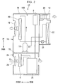
- FIG. 2 is a view showing a schematic constitution of a refrigeration cycle section included in a transportation refrigeration unit in the first embodiment of the present invention.
- FIG. 3 is a view showing a schematic constitution of the transportation refrigeration unit in the first embodiment of the present invention.
- the transportation refrigeration unit 13 includes a box body 14.
- the box body 14 includes a partition wall 15 configured to partition its internal space into upper and lower compartments.
- the box body 14 includes an upper box section 16 disposed above the partition wall 15 and a lower box section 24 disposed below the partition wall 15.
- a compressor 18, outdoor heat exchangers 20 (condensers), and outdoor heat exchange fans 19 which constitute a refrigeration cycle section 100 of the transportation refrigeration unit 13 are accommodated in the upper box section 16.
- a decompression mechanism 21 an expansion valve
- an indoor heat exchanger 22 an evaporator
- an indoor heat exchange fan 23 which are other components included in the refrigeration cycle section 100 of the transportation refrigeration unit 13 are accommodated in the container 10.
- the two outdoor heat exchange fans 19 are disposed side by side in vertical direction at a center in the width direction of the vehicle
- the outdoor heat exchangers 20 is disposed one by one at each side in the width direction of the vehicle.
- Upper box section 16 include exhaust ports M respectively at both sides in the width direction of the vehicle (left and right sides in FIG. 3 ).
- the exhaust ports M can discharge air A taken into the upper box section 16 through the outdoor heat exchange fans 19.
- a power source 25, an electric component unit 27, etc. are accommodated in the lower box section 24 of the box body 14.
- a diesel engine can be used as the power source 25.
- the above-described compressor 18 is driven using power output from the power source 25.
- a radiator R see FIG. 2
- a ventilation fan 26 a blower section
- an opening configured to take the air A into the lower box section 24 is disposed at an opposite side of the container 10 to surround the power source 25, and an opening configured to discharge the air A that is taken in is disposed at a side of the container.
- the openings are disposed at both sides in the width direction of the vehicle like a right opening section 32 and a left opening section 33 to be described below shown in FIG. 3 .
- a refrigerant compressed by the compressor 18 is first sent to the outdoor heat exchangers 20 through pipes.
- the refrigerant sent to the outdoor heat exchangers 20 exchanges heat with external air supplied through the outdoor heat exchange fans 19 to be cooled.
- the cooled refrigerant is sent to and depressurized in the decompression mechanism 21 in the container 10 and is then sent to the indoor heat exchanger 22.
- the air in the container 10 is supplied to the indoor heat exchanger 22 through the indoor heat exchange fan 23. For this reason, the air in the container 10 exchanges heat with the refrigerant of the indoor heat exchanger 22 to cool the air in the container 10.
- the refrigerant which exchanged heat with the air in the container 10 is returned to the compressor 18 in the box body 14, and the above-described cycle is iterated.
- the compressor 18 in the embodiment is the compressor 18 driven by a motor, and the power source 25 serving as a diesel engine drives a power generator (not shown).
- the power generator converts rotational energy of the diesel engine into electric energy and supplies electric power to a battery for driving the motor (not shown) or a control circuit configured to operate the motor.
- a silencer S of the diesel engine serving as the power source 25 in the embodiment is accommodated in the upper box section 16.
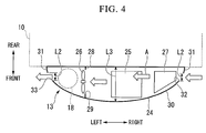
- FIG. 4 is a view showing a layout of the lower box section 24 of the box body 14 from above in the first embodiment of the present invention.
- the power source 25 is disposed at a center in the width direction of the vehicle of the lower box section 24.
- the electric component unit 27 is disposed to the right in the width direction of the vehicle relative to the power source 25 of the lower box section 24 (a first side).
- the above-described ventilation fan 26 is disposed to the left in the width direction of the vehicle relative to the power source 25 (a second side).
- the ventilation fan 26 is provided at an opening 29 of a partition wall 28 configured to separate the internal space of the lower box section 24 into left and right compartments.
- the compressor 18 may be provided at the lower box section 24.
- An alternative case in which the compressor 18 is provided in a left space relative to the ventilation fan 26 of the lower box section 24 is illustrated using a broken line in FIGS. 3 and 4 .
- a decorative panel 30 is attached to the front side of the lower box section 24 opposite to the front wall 11 of the container 10.
- the decorative panel 30 in the embodiment is curvedly formed to be convex forward.
- the decorative panel 30 can be attached and detached during maintenance, etc.
- the right opening section 32 (the opening section) and the left opening section 33 (the opening section) are formed near left and right edges 31 of the decorative panel 30 of the lower box section 24.
- Dimensions L2 of the right opening section 32 and the left opening section 33 in forward and rearward directions are formed to be smaller than a dimension L3 of the lower box section 24 in forward and rearward directions.
- the right opening section 32 and the left opening section 33 are outwardly open through in the width direction of the vehicle by being formed in this way.
- FIG. 5 is an enlarged view of an electric component unit of FIG. 4 in the first embodiment of the present invention.
- the electric component unit 27 includes a first electric component box 34 and a second electric component box 35.
- the first electric component box 34 accommodates strong electric system facilities.
- strong electric system facilities include a plurality of apparatuses which mainly handle an alternating current (AC) (e.g., about AC 200 to 480 V).
- AC alternating current
- the apparatuses included in the strong electric system facilities such as an inverter configured to perform motor control on the compressor 18, a converter configured to convert AC electric power generated by a power generator into direct current (DC) electric power, and a switch configured to turn on/off such circuits can be exemplarily illustrated.
- the second electric component box 35 accommodates light electric system facilities.
- Such light electric system facilities include a semiconductor circuit, a relay, and so on which are mainly driven by a DC current (e.g., DC 10 to 16 V).
- the apparatuses included in the light electric system facilities such as a control circuit configured to control opening and closing of valves (not shown) constituting the refrigeration cycle section 100, and a fuel injector of a diesel engine can be exemplarily illustrated.
- Strong electric system facilities, and so on handling an AC current are not accommodated in the second electric component box 35 at all. For this reason, there is no need for the light electric system facilities accommodated in the second electric component box 35 to actively radiate the heat since heat generation due to the light electric system facilities themselves never become a problem.
- the first electric component box 34 in the embodiment is formed by a material with good heat conductivity (e.g., a metal such as aluminum).
- a shield effect of the first electric component box 34 with respect to electromagnetic waves emitted from strong electric system facilities is also acquired.
- the second electric component box 35 may also be formed by a metal such as, for example, aluminum and stainless steel, to shield electromagnetic waves. As described above, when the second electric component box 35 is formed by a metal such as aluminum and stainless steel, a greater shield effect is acquired, and an influence of the electromagnetic waves from the strong electric system facilities on the light electric system facilities can be prevented.
- the first electric component box 34 and the second electric component box 35 in the embodiment are disposed to be arranged at an interval in forward and rearward directions.
- a passage 36 through which the air A can flow is formed between the first electric component box 34 and the second electric component box 35.
- the right opening section 32 is formed at a position extending the passage 36 to the right side. For this reason, the air A flowing in from the right opening section 32 smoothly flows into the passage 36.
- the first electric component box 34 has a heat exchange surface 37 at a side at which the second electric component box 35 is disposed in forward and rearward directions.
- a portion in the first electric component box 34 forming the above-described passage 36 is the heat exchange surface 37 which can exchange heat with the air A flowing through the passage 36.
- the strong electric system facilities accommodated inside the first electric component box 34 are attached to the heat exchange surface 37 so as to be able to transfer heat.
- the strong electric system facilities can exchange heat with the air A flowing through the passage 36 by means of the heat exchange surface 37.
- a heat radiating fin section 38 protruding toward the second electric component box 35 is formed on the heat exchange surface 37 in the embodiment.
- a surface area of the heat exchange surface 37 is increased due to the fin section 38 so that the area of the heat exchange surface 37 which can come into contact with the air A passing through the passage 36 can be increased.
- the fin section 38 may be omitted when the strong electric system facilities can be sufficiently cooled using the planar heat exchange surface 37 without the fin section 38.
- FIG. 6 is a view showing a state in which the first electric component box of FIG. 5 is swung forward.
- a corner C of the first electric component box 34 formed by a surface 34a facing forward and a surface 34b facing a central side in the width direction of the vehicle is supported by a frame section 40 which extends vertically via a hinge 39.
- the hinge 39 in the embodiment is attached such that its axis is vertical.
- the first electric component box 34 can swing about an axis of the hinge 39 in forward and rearward directions while the decorative panel 30 is removed.
- the forward facing surface 34a of the first electric component box 34 in the embodiment is inclined towards the rear of the vehicle considered outwardly in the width direction of the vehicle to avoid the curved decorative panel 30.
- the first electric component box 34 is formed in a trapezoidal shape when viewed from above.
- the air A flowing into the box body 14 from the right opening section 32 can be brought into contact and exchange heat with the heat exchange surface 37 of the electric component unit 27 at the right side of the power source 25 by means of an operation of the ventilation fan 26.
- the strong electric system facilities connected to the heat exchange surface 37 can be cooled through the heat exchange.
- the air A can be discharged from the left opening section 33 outside the box body 14. For this reason, the strong electric system facilities can be efficiently cooled using the air A for cooling the power source 25.
- the right opening section 32 and the left opening section 33 are respectively provided at a right side and a left side of the box body 14 in the width direction thereof, noise of the power source 25 can be prevented from leaking outside compared with when the plurality of openings 29 are provided at the decorative panel 30.
- a space between the first electric component box 34 and the second electric component box 35 can be used as the passage 36 through which the air A flows. For this reason, a cross section of the passage 36 is reduced to increase a flow rate of the air A so that heat exchange can be efficiently performed.
- surfaces opposite to each other serve as shields, and heat, electromagnetic waves, and so on from the strong electric system facilities can be prevented from adversely affecting the light electric system facilities. Since the first electric component box 34 is disposed in the front of the passage 36 between the first electric component box 34 and the second electric component box 35, noise of the power source 25 passing through the passage 36 can be prevented from leaking forward from the box body 14.
- the heat exchange surface 37 includes the heat radiating fin section 38 so that the surface area of the heat exchange surface 37 can be increased. For this reason, the efficiency of heat exchange can be improved to prompt heat radiation of the strong electric system facilities.
- the load capacity of the container 10 can be prevented from decreasing.
- quietness and cooling performance of the strong electric system facilities can be enhanced, merchantability of the trailer 3 can be improved.
- the transportation refrigeration unit 13 in a second embodiment of the present invention will be described based on the drawings.
- the second embodiment is different from the above-described first embodiment only in that structures of the electric component unit 27 differ. For this reason, the same components as those of the first embodiment will be described with the same reference numerals, and overlapping description with the first embodiment thereof will be omitted.
- FIG. 7 is a view corresponding to FIG. 5 in the second embodiment of the present invention.
- the electric component unit 27 includes the first electric component box 34 and the second electric component box 35.
- the first electric component box 34 and a rear wall 24a of the lower box section 24 are disposed at an interval in forward and rearward directions.
- a space between the first electric component box 34 and the rear wall 24a is the passage 36 of the air A flowing into the lower box section 24 by means of the ventilation fan 26 (see FIG. 4 ).
- the strong electric system facilities are accommodated in the first electric component box 34 as in the first embodiment.
- a surface of the first electric component box 34 facing the rear wall 24a is the heat exchange surface 37.
- the strong electric system facilities accommodated in the first electric component box 34 are attached to the heat exchange surface 37 so as to be able to transfer heat.
- the heat radiating fin section 38 is formed on the heat exchange surface 37 as in the first embodiment.
- the second electric component box 35 is disposed in the front of the first electric component box 34 and is integrally disposed with the first electric component box 34. Only the light electric system facilities are accommodated in the second electric component box 35.
- the electric component unit 27 with such a constitution may be configured to be swingable with respect to the frame section 40 (see FIGS. 5 and 6 ) using the hinge 39 as in the first embodiment. Also, when the first electric component box 34 and the second electric component box 35 are not formed as a single body, only the second electric component box 35 disposed in the front may be attached to be swingable with respect to the frame section 40 via the hinge 39 as in the first embodiment.
- the passage 36 through which the air A passes can be disposed closer to the container 10 than in the first embodiment.
- the first electric component box 34 and the second electric component box 35 are disposed in the front of the passage 36, noise from the power source 25 can be further prevented from being transferred to the front of the vehicle 1 through the passage 36 and leaking.
- the right opening section 32 can be disposed even closer to the container 10. For this reason, for example, the right opening section 32 and the left opening section 33 can be maximally separated from each other.
- the air A discharged from the left opening section 33 can be prevented from flowing in again from the right opening section 32.
- the cooling efficiency can be improved.
- the third embodiment is different from the above-described first embodiment only in that structures of the electric component unit 27 differ. For this reason, the same components as those of the first embodiment will be described with the same reference numerals, and an overlapping description with the first embodiment thereof will be omitted.
- FIG. 8 is a view taken by viewing an electric component unit from the front in the third embodiment of the present invention.
- the electric component unit 27 in the embodiment includes the first electric component box 34 and the second electric component box 35.
- the first electric component box 34 and the second electric component box 35 are disposed at an interval in vertical direction.
- the strong electric system facilities are accommodated in the first electric component box 34, and the light electric system facilities are accommodated in the second electric component box 35.
- the second electric component box 35 is disposed above the first electric component box 34.
- An upper surface of the first electric component box 34 is the heat exchange surface 37, and the heat radiating fin section 38 is formed on the heat exchange surface 37.
- the space between the first electric component box 34 and the second electric component box 35 can be used as the passage 36 through which the air A flows as in the first embodiment.
- the cross section of the passage 36 is reduced to increase the flow rate of the air A so that heat exchange can be efficiently performed.
- the strong electric system facilities and the light electric system facilities are accommodated in separate boxes, heat, electromagnetic waves, and so on from the strong electric system facilities can be prevented from adversely affecting the light electric system facilities.
- the first electric component box 34 and the second electric component box 35 are disposed to be vertically arranged, access to both of the first electric component box 34 and the second electric component box 35 is enhanced without a support structure of the electric component unit 27 becoming complicated. For this reason, a load applied to an operator during maintenance can be reduced.
- the first electric component box 34 and the second electric component box 35 are disposed to be vertically arranged so that the first electric component box 34 and the second electric component box 35 are above and below the passage 36 between the first electric component box 34 and the second electric component box 35.
- noise of the power source 25 passing through the passage 36 can be prevented from leaking in upward and downward directions of the box body 14.
- the present invention is not limited to the above-mentioned embodiments and includes various modified examples of the above-described embodiments within a range not departing from the scope of the present invention.
- specific shapes and configurations described in the embodiments are merely examples and can be appropriately changed.
- the second electric component box 35 is disposed above the first electric component box 34 has been described in the above-described third embodiment, but the arrangement of the first electric component box 34 and the second electric component box 35 may be changed.
- a diesel engine is used as an exemplary example of the power source 25 in the above-described embodiments.
- the power source 25 is not limited to a diesel engine.
- An internal combustion engine other than a diesel engine may be used.
- the cases in which the power generator is driven by the diesel engine, and the compressor 18 is driven using the power have been described in the embodiments.
- the internal combustion engine may be omitted and the compressor 18 may be driven using the power charged into a rechargeable battery. In this case, after the electric component unit 27 is cooled using the air A flowing into the lower box section 24 by means of the ventilation fan 26, the rechargeable battery can be cooled.
- the flash mount type transportation refrigeration unit 13 has been described as an example in the above-described embodiments, but the present invention may be applied to a so-called nose mount type transportation refrigeration unit 13.
Landscapes
- Engineering & Computer Science (AREA)
- Physics & Mathematics (AREA)
- Mechanical Engineering (AREA)
- Thermal Sciences (AREA)
- Chemical & Material Sciences (AREA)
- Combustion & Propulsion (AREA)
- General Engineering & Computer Science (AREA)
- Devices That Are Associated With Refrigeration Equipment (AREA)
Abstract
Description
- The present disclosure relates to a transportation refrigeration unit and a trailer.
- There are trailer such as semitrailer towed by tractors on which containers having transportation refrigeration units are mounted. Such transportation refrigeration units include a so-called nose mount type transportation refrigeration unit which extends from a front wall of a container to a space above a tractor and a so-called flash mount type transportation refrigeration unit installed at a narrow space between a container and a tractor.
- Transportation refrigeration units also include a type of transportation refrigeration unit which is driven by power supplied from a tractor and a type of transportation refrigeration unit which can be independently driven without a tractor. In the independent type of transportation refrigeration unit, a sub engine, and so on are mounted as a power source dedicated to the refrigeration unit separate from an engine of a tractor.
- Patent Citation 1 discloses a transportation refrigeration unit on which a sub engine for power generation is mounted. In the transportation refrigeration unit of Patent Citation 1, a power generator is configured to be driven by the sub engine to supply power from the power generator to a compressor of the refrigeration unit. In addition, the transportation refrigeration unit drives a radiator fan using the sub engine, takes in external air from a suction ventilation port formed in a lateral surface of a box body and a suction ventilation port formed in a front surface of the box body, and cools a controller, a radiator, and an engine. The air used for the cooling is discharged from a discharge ventilation port formed in a lateral surface opposite to the suction ventilation port.
- [Patent Citation 1] Japanese Unexamined Patent Application, First Publication No.
S62-091773 - In the above-described transportation refrigeration unit disclosed in Patent Citation 1, there is a demand for further noise reduction. However, in this type of transportation limitation unit, it is necessary not to reduce a volume of a container and there is a restriction on an installation space. For this reason, it is difficult to install a soundproof material, and so on. In addition, a plurality of openings are formed in the transportation refrigeration unit disclosed in Patent Citation 1. For this reason, the noise of the engine easily leaks outside through the openings. For example, if areas of the openings are reduced as a measure against noise, the amount of air supplied inside the box body is decreased while performance of a radiator fan is maintained. For this reason, a temperature of particularly strong electric system facilities inside the box body is likely to increase and adversely affect surrounding facilities.
- The present invention provides a transportation refrigeration unit and a trailer= capable of reducing noise and efficiently cooling strong electric system facilities.
- According to a first aspect of the present invention, a transportation refrigeration unit includes: a transportation container; a box body provided at a front side of the transportation container and having opening sections at both sides in a width direction of the transportation container; a refrigeration cycle section having an evaporator disposed in the transportation container and a condenser, a compressor, and an expansion valve disposed in the box body; a power source provided at a center in a width direction in the box body and configured to generate power driving the compressor; a blower section disposed in the box body, configured to flow air into the box body from one of the opening sections provided at a first side in the width direction of the transportation container, and configured to discharge the air in the box body from the other opening section provided at a second side in the width direction of the transportation container; and an electric component unit disposed in the box body closer to the first side in the width direction of the transportation container than the power source and having strong electric system facilities configured to drive the compressor and light electric system facilities configured to control driving of the refrigeration cycle section, wherein a portion of an outer surface of the electric component unit is a heat exchange surface which is capable of exchanging heat with the air flowing into the box body and flowing in the width direction of the transportation container, and at least the strong electric system facilities are connected to the heat exchange surface so as to be capable of transferring heat.
- With such a constitution, the air flowing into the box body from the first side by operation of the blower section can be brought into contact and exchange heat with the heat exchange surface of the electric component unit at the first side of the power source. The strong electric system facilities connected to the heat exchange surface can be cooled through the heat exchange. Also, after the power source is cooled by the air used for the cooling of the strong electric system facilities, the air can be discharged outside the box body from the second side. For this reason, the strong electric system facilities can be efficiently cooled. In addition, since the opening sections are provided only at the first side and the second side in the width direction of the box body, noise of the power source can be prevented from leaking outside compared with when a plurality of opening sections is provided.
- According to a second aspect of the present invention, in the transportation refrigeration unit, the electric component unit in the first aspect may include a first electric component box configured to accommodate the strong electric system facilities and a second electric component box configured to accommodate the light electric system facilities, the first electric component box and the second electric component box may be disposed to be arranged at an interval in forward and rearward directions, and the first electric component box may have the heat exchange surface at a side at which the second electric component box is disposed in the forward and rearward directions.
- With such a constitution, a space between the first electric component box and the second electric component box can be used as the passage through which the air flows. For this reason, a cross section of the passage can be reduced to increase a flow rate of the air so that heat exchange is efficiently performed. In addition, since the strong electric system facilities and the light electric system facilities are accommodated in separate boxes, heat, electromagnetic waves, and so on from the strong electric system facilities can be prevented from adversely affecting the light electric system facilities. Also, since one of the first electric component box and the second electric component box is disposed in the front of the passage between the first electric component box and the second electric component box, noise of the power source passing through the passage can be limited from leaking forward from the box body.
- According to a third aspect of the present invention, in the second aspect, the transportation refrigeration unit may further include a frame section configured to support one of the first electric component box and the second electric component box which is disposed in the front to be swingable in forward and rearward directions.
- With such a constitution, the front electric component box between the first electric component box and the second electric component box supported by the frame section can swing forward, for example, so that the electric component box which is disposed in the rear can be easily accessed.
- According to a fourth aspect of the present invention, in the transportation refrigeration unit, the electric component unit in the first aspect may include a first electric component box configured to accommodate the strong electric system facilities and having the heat exchange surface; and a second electric component box configured to accommodate the light electric system facilities and configured such that the first electric component box and the second electric component box are disposed at an interval in vertical direction, wherein the first electric component box may have the heat exchange surface at a side at which the second electric component box is disposed in vertical direction.
- With such a constitution, the space between the first electric component box and the second electric component box can be used as the passage through which the air flows. For this reason, the cross section of the passage can be reduced to increase the flow rate of the air so that heat exchange is efficiently performed. In addition, since the strong electric system facilities and the light electric system facilities are accommodated in separate boxes, heat, electromagnetic waves, etc. from the strong electric system facilities can be prevented from adversely affecting the light electric system facilities. Also, since the first electric component box and the second electric component box are disposed to be vertically arranged, access to both of the first electric component box and the second electric component box is good. Thus, workloads imposed on an operator during maintenance can be reduced. The first electric component box and the second electric component box are disposed to be vertically arranged so that the first electric component box and the second electric component box are above and below the passage between the first electric component box and the second electric component box. Thus, noise of the power source passing through the passage can be prevented from leaking in upward and downward directions of the box body.
- According to a fifth aspect of the present invention, in the transportation refrigeration unit, the heat exchange surface in any one of the first to fourth aspects may have a heat radiating fin section.
- With such a constitution, since a surface area of the heat exchange surface can be increased, efficiency of heat exchange can be improved to promote heat radiation of the strong electric system facilities.
- According to a sixth aspect of the present invention, a trailer includes the transportation refrigeration unit in any one of the first to fifth aspects.
- With such a constitution, since the transportation refrigeration unit does not become larger, the load capacity can be prevented from being decreased. In addition, since quietness and cooling performance of the strong electric system facilities can be enhanced, the merchantability can be further improved.
- According to the above-described transportation refrigeration unit, noise can be reduced and strong electric system facilities can be efficiently cooled.
-
-
FIG. 1 is a side view of a vehicle in a first embodiment of the present invention. -
FIG. 2 is a view showing a schematic constitution of a refrigeration cycle section included in a transportation refrigeration unit in the first embodiment of the present invention. -
FIG. 3 is a view showing a schematic constitution of the transportation refrigeration unit in the first embodiment of the present invention. -
FIG. 4 is a view showing a layout of a lower box section of a box body from above in the first embodiment of the present invention. -
FIG. 5 is an enlarged view of an electric component unit ofFIG. 4 in the first embodiment of the present invention. -
FIG. 6 is a view showing a state in which a first electric component box ofFIG. 5 swings forward. -
FIG. 7 is a view corresponding toFIG. 5 in a second embodiment of the present invention. -
FIG. 8 is a view of an electric component unit from the front in a third embodiment of the present invention. - Hereinafter, a transportation refrigeration unit and a trailer in a first embodiment of the present invention will be described based on the drawings.
-
FIG. 1 is a side view of a vehicle 1 in the first embodiment of the present invention. - As shown in
FIG. 1 , the vehicle 1 in the embodiment includes atrailer 3 towed by atractor 2. - The
tractor 2 includes aframe 5, a cab 6, andwheels 7. - The
frame 5 extends in forward and rearward directions of thetractor 2. A coupler (not shown) configured to connect thetrailer 3 is provided at a rear upper surface of theframe 5, and the cab 6 serving as a driver's cab is provided in the front of theframe 5. Thetractor 2 in the embodiment is exemplarily illustrated as a so-called cab-over type tractor in which the cab 6 is disposed above a traveling engine (not shown). In the cab-over type tractor, thewheels 7 are provided in the front and rear of theframe 5. - The
trailer 3 includes achassis 8,wheels 9, and a container (a transportation container) 10. - The
chassis 8 is formed to extend in forward and rearward directions. Thechassis 8 includes a connecting pin (not shown) in the front thereof. The connecting pin is provided to protrude downward from thechassis 8 and can be inserted into and extracted from the above-described coupler of thetractor 2. Thetractor 2 and thetrailer 3 are connected to each other by inserting the coupling pin into the coupler. - The
wheels 9 are rotatably attached to the rear of thechassis 8. In thetrailer 3 in the embodiment, two sets ofwheels 9 are disposed to be arranged side by side in forward and rearward directions, but the number and the arrangement of thewheels 9 are not limited thereto. - The
container 10 is formed in a box shape which is supported by thechassis 8 from below. Thecontainer 10 in the embodiment has a rectangular parallelepiped shape which length extends in forward and rearward directions in which thechassis 8 extends. The front of thecontainer 10 is disposed above theframe 5 of thetractor 2 while thetrailer 3 is connected to thetractor 2. In this state, a predetermined space is formed between afront wall 11 of thecontainer 10 and arear wall 12 of the cab 6. - The
container 10 includes atransportation refrigeration unit 13 configured to cool air therein. Thetransportation refrigeration unit 13 is attached to the front wall (a front surface) 11 of thecontainer 10. In other words, thetransportation refrigeration unit 13 is disposed in the space between thefront wall 11 of thecontainer 10 and therear wall 12 of the cab 6. - A dimension L1 of the
transportation refrigeration unit 13 in forward and rearward directions is formed to be sufficiently thin not to affect a volume of thecontainer 10. The dimension L1 of thetransportation refrigeration unit 13 in forward and rearward directions is set to be as large as possible within a range in which the cab 6 of thetractor 2 does not come into contact with thetransportation refrigeration unit 13 when the vehicle 1 turns. Thetransportation refrigeration unit 13 has a quadrangular shape which is slightly smaller than thefront wall 11 viewed from the front so that it does not protrude above thecontainer 10 or in a width direction of the vehicle. -
FIG. 2 is a view showing a schematic constitution of a refrigeration cycle section included in a transportation refrigeration unit in the first embodiment of the present invention.FIG. 3 is a view showing a schematic constitution of the transportation refrigeration unit in the first embodiment of the present invention. - As shown in
FIG. 2 , thetransportation refrigeration unit 13 includes abox body 14. Thebox body 14 includes apartition wall 15 configured to partition its internal space into upper and lower compartments. Thebox body 14 includes anupper box section 16 disposed above thepartition wall 15 and alower box section 24 disposed below thepartition wall 15. - A
compressor 18, outdoor heat exchangers 20 (condensers), and outdoorheat exchange fans 19 which constitute arefrigeration cycle section 100 of thetransportation refrigeration unit 13 are accommodated in theupper box section 16. On the other hand, a decompression mechanism 21 (an expansion valve), an indoor heat exchanger 22 (an evaporator), and an indoorheat exchange fan 23 which are other components included in therefrigeration cycle section 100 of thetransportation refrigeration unit 13 are accommodated in thecontainer 10. As shown inFIG. 3 , in theupper box section 16 in the embodiment, the two outdoorheat exchange fans 19 are disposed side by side in vertical direction at a center in the width direction of the vehicle, and theoutdoor heat exchangers 20 is disposed one by one at each side in the width direction of the vehicle.Upper box section 16 include exhaust ports M respectively at both sides in the width direction of the vehicle (left and right sides inFIG. 3 ). The exhaust ports M can discharge air A taken into theupper box section 16 through the outdoorheat exchange fans 19. - As shown in
FIGS. 2 and3 , apower source 25, anelectric component unit 27, etc. are accommodated in thelower box section 24 of thebox body 14. For example, a diesel engine can be used as thepower source 25. The above-describedcompressor 18 is driven using power output from thepower source 25. When a diesel engine is used as thepower source 25 in the embodiment, a radiator R (seeFIG. 2 ) and a ventilation fan 26 (a blower section) which can send cooling air to the radiator R are provided in thelower box section 24. Here, inFIG. 2 , for the convenience of illustration, an opening configured to take the air A into thelower box section 24 is disposed at an opposite side of thecontainer 10 to surround thepower source 25, and an opening configured to discharge the air A that is taken in is disposed at a side of the container. However, to be exact, the openings are disposed at both sides in the width direction of the vehicle like aright opening section 32 and aleft opening section 33 to be described below shown inFIG. 3 . - According to the above-described
refrigeration cycle section 100, a refrigerant compressed by thecompressor 18 is first sent to theoutdoor heat exchangers 20 through pipes. The refrigerant sent to theoutdoor heat exchangers 20 exchanges heat with external air supplied through the outdoorheat exchange fans 19 to be cooled. The cooled refrigerant is sent to and depressurized in thedecompression mechanism 21 in thecontainer 10 and is then sent to theindoor heat exchanger 22. The air in thecontainer 10 is supplied to theindoor heat exchanger 22 through the indoorheat exchange fan 23. For this reason, the air in thecontainer 10 exchanges heat with the refrigerant of theindoor heat exchanger 22 to cool the air in thecontainer 10. Then, the refrigerant which exchanged heat with the air in thecontainer 10 is returned to thecompressor 18 in thebox body 14, and the above-described cycle is iterated. - The
compressor 18 in the embodiment is thecompressor 18 driven by a motor, and thepower source 25 serving as a diesel engine drives a power generator (not shown). The power generator converts rotational energy of the diesel engine into electric energy and supplies electric power to a battery for driving the motor (not shown) or a control circuit configured to operate the motor. As shown inFIG. 2 , a silencer S of the diesel engine serving as thepower source 25 in the embodiment is accommodated in theupper box section 16. -
FIG. 4 is a view showing a layout of thelower box section 24 of thebox body 14 from above in the first embodiment of the present invention. - As shown in
FIGS. 3 and4 , thepower source 25 is disposed at a center in the width direction of the vehicle of thelower box section 24. Theelectric component unit 27 is disposed to the right in the width direction of the vehicle relative to thepower source 25 of the lower box section 24 (a first side). The above-describedventilation fan 26 is disposed to the left in the width direction of the vehicle relative to the power source 25 (a second side). Theventilation fan 26 is provided at anopening 29 of apartition wall 28 configured to separate the internal space of thelower box section 24 into left and right compartments. Here, the case in which thecompressor 18 is accommodated in theupper box section 16 has been described in the above description of theupper box section 16. However, as shown inFIGS. 3 and4 , thecompressor 18 may be provided at thelower box section 24. An alternative case in which thecompressor 18 is provided in a left space relative to theventilation fan 26 of thelower box section 24 is illustrated using a broken line inFIGS. 3 and4 . - As shown in
FIG. 4 , adecorative panel 30 is attached to the front side of thelower box section 24 opposite to thefront wall 11 of thecontainer 10. Thedecorative panel 30 in the embodiment is curvedly formed to be convex forward. Thedecorative panel 30 can be attached and detached during maintenance, etc. The right opening section 32 (the opening section) and the left opening section 33 (the opening section) are formed near left andright edges 31 of thedecorative panel 30 of thelower box section 24. - Dimensions L2 of the
right opening section 32 and theleft opening section 33 in forward and rearward directions are formed to be smaller than a dimension L3 of thelower box section 24 in forward and rearward directions. Theright opening section 32 and theleft opening section 33 are outwardly open through in the width direction of the vehicle by being formed in this way. -
FIG. 5 is an enlarged view of an electric component unit ofFIG. 4 in the first embodiment of the present invention. - As shown in
FIG. 5 , theelectric component unit 27 includes a firstelectric component box 34 and a secondelectric component box 35. - The first
electric component box 34 accommodates strong electric system facilities. Such strong electric system facilities include a plurality of apparatuses which mainly handle an alternating current (AC) (e.g., about AC 200 to 480 V). For example, the apparatuses included in the strong electric system facilities, such as an inverter configured to perform motor control on thecompressor 18, a converter configured to convert AC electric power generated by a power generator into direct current (DC) electric power, and a switch configured to turn on/off such circuits can be exemplarily illustrated. - The second
electric component box 35 accommodates light electric system facilities. Such light electric system facilities include a semiconductor circuit, a relay, and so on which are mainly driven by a DC current (e.g.,DC 10 to 16 V). For example, the apparatuses included in the light electric system facilities, such as a control circuit configured to control opening and closing of valves (not shown) constituting therefrigeration cycle section 100, and a fuel injector of a diesel engine can be exemplarily illustrated. Strong electric system facilities, and so on handling an AC current are not accommodated in the secondelectric component box 35 at all. For this reason, there is no need for the light electric system facilities accommodated in the secondelectric component box 35 to actively radiate the heat since heat generation due to the light electric system facilities themselves never become a problem. - Here, the first
electric component box 34 in the embodiment is formed by a material with good heat conductivity (e.g., a metal such as aluminum). When the firstelectric component box 34 is formed of a metal such as aluminum, a shield effect of the firstelectric component box 34 with respect to electromagnetic waves emitted from strong electric system facilities is also acquired. The secondelectric component box 35 may also be formed by a metal such as, for example, aluminum and stainless steel, to shield electromagnetic waves. As described above, when the secondelectric component box 35 is formed by a metal such as aluminum and stainless steel, a greater shield effect is acquired, and an influence of the electromagnetic waves from the strong electric system facilities on the light electric system facilities can be prevented. - The first
electric component box 34 and the secondelectric component box 35 in the embodiment are disposed to be arranged at an interval in forward and rearward directions. Thus, apassage 36 through which the air A can flow is formed between the firstelectric component box 34 and the secondelectric component box 35. In the embodiment, theright opening section 32 is formed at a position extending thepassage 36 to the right side. For this reason, the air A flowing in from theright opening section 32 smoothly flows into thepassage 36. - The first
electric component box 34 has aheat exchange surface 37 at a side at which the secondelectric component box 35 is disposed in forward and rearward directions. In other words, a portion in the firstelectric component box 34 forming the above-describedpassage 36 is theheat exchange surface 37 which can exchange heat with the air A flowing through thepassage 36. The strong electric system facilities accommodated inside the firstelectric component box 34 are attached to theheat exchange surface 37 so as to be able to transfer heat. Thus, the strong electric system facilities can exchange heat with the air A flowing through thepassage 36 by means of theheat exchange surface 37. - Also, a heat radiating
fin section 38 protruding toward the secondelectric component box 35 is formed on theheat exchange surface 37 in the embodiment. A surface area of theheat exchange surface 37 is increased due to thefin section 38 so that the area of theheat exchange surface 37 which can come into contact with the air A passing through thepassage 36 can be increased. In the embodiment, the case in which thefin section 38 is provided is an exemplary example. However, thefin section 38 may be omitted when the strong electric system facilities can be sufficiently cooled using the planarheat exchange surface 37 without thefin section 38. -
FIG. 6 is a view showing a state in which the first electric component box ofFIG. 5 is swung forward. - As shown in
FIGS. 5 and 6 , a corner C of the firstelectric component box 34 formed by asurface 34a facing forward and asurface 34b facing a central side in the width direction of the vehicle is supported by aframe section 40 which extends vertically via ahinge 39. Thehinge 39 in the embodiment is attached such that its axis is vertical. Thus, the firstelectric component box 34 can swing about an axis of thehinge 39 in forward and rearward directions while thedecorative panel 30 is removed. - The
forward facing surface 34a of the firstelectric component box 34 in the embodiment is inclined towards the rear of the vehicle considered outwardly in the width direction of the vehicle to avoid the curveddecorative panel 30. Thus, the firstelectric component box 34 is formed in a trapezoidal shape when viewed from above. - Therefore, according to the above-described first embodiment, the air A flowing into the
box body 14 from theright opening section 32 can be brought into contact and exchange heat with theheat exchange surface 37 of theelectric component unit 27 at the right side of thepower source 25 by means of an operation of theventilation fan 26. The strong electric system facilities connected to theheat exchange surface 37 can be cooled through the heat exchange. Also, after thepower source 25 is cooled by the air A used for cooling of the strong electric system facilities, the air A can be discharged from theleft opening section 33 outside thebox body 14. For this reason, the strong electric system facilities can be efficiently cooled using the air A for cooling thepower source 25. In addition, since theright opening section 32 and theleft opening section 33 are respectively provided at a right side and a left side of thebox body 14 in the width direction thereof, noise of thepower source 25 can be prevented from leaking outside compared with when the plurality ofopenings 29 are provided at thedecorative panel 30. - Also, according to the first embodiment, a space between the first
electric component box 34 and the secondelectric component box 35 can be used as thepassage 36 through which the air A flows. For this reason, a cross section of thepassage 36 is reduced to increase a flow rate of the air A so that heat exchange can be efficiently performed. In addition, since the strong electric system facilities and the light electric system facilities are accommodated in separate boxes, surfaces opposite to each other serve as shields, and heat, electromagnetic waves, and so on from the strong electric system facilities can be prevented from adversely affecting the light electric system facilities. Since the firstelectric component box 34 is disposed in the front of thepassage 36 between the firstelectric component box 34 and the secondelectric component box 35, noise of thepower source 25 passing through thepassage 36 can be prevented from leaking forward from thebox body 14. - According to the first embodiment, the
heat exchange surface 37 includes the heat radiatingfin section 38 so that the surface area of theheat exchange surface 37 can be increased. For this reason, the efficiency of heat exchange can be improved to prompt heat radiation of the strong electric system facilities. - Since the
transportation refrigeration unit 13 does not become larger, the load capacity of thecontainer 10 can be prevented from decreasing. In addition, since quietness and cooling performance of the strong electric system facilities can be enhanced, merchantability of thetrailer 3 can be improved. - Next, the
transportation refrigeration unit 13 in a second embodiment of the present invention will be described based on the drawings. The second embodiment is different from the above-described first embodiment only in that structures of theelectric component unit 27 differ. For this reason, the same components as those of the first embodiment will be described with the same reference numerals, and overlapping description with the first embodiment thereof will be omitted. -
FIG. 7 is a view corresponding toFIG. 5 in the second embodiment of the present invention. - As shown in
FIG. 7 , theelectric component unit 27 includes the firstelectric component box 34 and the secondelectric component box 35. - The first
electric component box 34 and arear wall 24a of thelower box section 24 are disposed at an interval in forward and rearward directions. A space between the firstelectric component box 34 and therear wall 24a is thepassage 36 of the air A flowing into thelower box section 24 by means of the ventilation fan 26 (seeFIG. 4 ). The strong electric system facilities are accommodated in the firstelectric component box 34 as in the first embodiment. A surface of the firstelectric component box 34 facing therear wall 24a is theheat exchange surface 37. The strong electric system facilities accommodated in the firstelectric component box 34 are attached to theheat exchange surface 37 so as to be able to transfer heat. Also, the heat radiatingfin section 38 is formed on theheat exchange surface 37 as in the first embodiment. - The second
electric component box 35 is disposed in the front of the firstelectric component box 34 and is integrally disposed with the firstelectric component box 34. Only the light electric system facilities are accommodated in the secondelectric component box 35. Theelectric component unit 27 with such a constitution may be configured to be swingable with respect to the frame section 40 (seeFIGS. 5 and 6 ) using thehinge 39 as in the first embodiment. Also, when the firstelectric component box 34 and the secondelectric component box 35 are not formed as a single body, only the secondelectric component box 35 disposed in the front may be attached to be swingable with respect to theframe section 40 via thehinge 39 as in the first embodiment. - Therefore, according to the above-described second embodiment, the
passage 36 through which the air A passes can be disposed closer to thecontainer 10 than in the first embodiment. In other words, since the firstelectric component box 34 and the secondelectric component box 35 are disposed in the front of thepassage 36, noise from thepower source 25 can be further prevented from being transferred to the front of the vehicle 1 through thepassage 36 and leaking. Also, theright opening section 32 can be disposed even closer to thecontainer 10. For this reason, for example, theright opening section 32 and theleft opening section 33 can be maximally separated from each other. Thus, the air A discharged from theleft opening section 33 can be prevented from flowing in again from theright opening section 32. As a result, the cooling efficiency can be improved. - Next, the
transportation refrigeration unit 13 in a third embodiment of the present invention will be described based on the drawings. The third embodiment is different from the above-described first embodiment only in that structures of theelectric component unit 27 differ. For this reason, the same components as those of the first embodiment will be described with the same reference numerals, and an overlapping description with the first embodiment thereof will be omitted. -
FIG. 8 is a view taken by viewing an electric component unit from the front in the third embodiment of the present invention. - As shown in
FIG. 8 , theelectric component unit 27 in the embodiment includes the firstelectric component box 34 and the secondelectric component box 35. - The first
electric component box 34 and the secondelectric component box 35 are disposed at an interval in vertical direction. The strong electric system facilities are accommodated in the firstelectric component box 34, and the light electric system facilities are accommodated in the secondelectric component box 35. In the embodiment, the secondelectric component box 35 is disposed above the firstelectric component box 34. An upper surface of the firstelectric component box 34 is theheat exchange surface 37, and the heat radiatingfin section 38 is formed on theheat exchange surface 37. - Therefore, according to the above-described third embodiment, the space between the first
electric component box 34 and the secondelectric component box 35 can be used as thepassage 36 through which the air A flows as in the first embodiment. For this reason, the cross section of thepassage 36 is reduced to increase the flow rate of the air A so that heat exchange can be efficiently performed. In addition, since the strong electric system facilities and the light electric system facilities are accommodated in separate boxes, heat, electromagnetic waves, and so on from the strong electric system facilities can be prevented from adversely affecting the light electric system facilities. - Also, according to the third embodiment, since the first
electric component box 34 and the secondelectric component box 35 are disposed to be vertically arranged, access to both of the firstelectric component box 34 and the secondelectric component box 35 is enhanced without a support structure of theelectric component unit 27 becoming complicated. For this reason, a load applied to an operator during maintenance can be reduced. - The first
electric component box 34 and the secondelectric component box 35 are disposed to be vertically arranged so that the firstelectric component box 34 and the secondelectric component box 35 are above and below thepassage 36 between the firstelectric component box 34 and the secondelectric component box 35. Thus, noise of thepower source 25 passing through thepassage 36 can be prevented from leaking in upward and downward directions of thebox body 14. - The present invention is not limited to the above-mentioned embodiments and includes various modified examples of the above-described embodiments within a range not departing from the scope of the present invention. In other words, specific shapes and configurations described in the embodiments are merely examples and can be appropriately changed.
- For example, the case in which the second
electric component box 35 is disposed above the firstelectric component box 34 has been described in the above-described third embodiment, but the arrangement of the firstelectric component box 34 and the secondelectric component box 35 may be changed. - The cases in which the
heat exchange surface 37 is provided only at a side of thepassage 36 of the firstelectric component box 34 have been described in the above-described embodiments, but another surface forming the firstelectric component box 34 may be used as theheat exchange surface 37. - A diesel engine is used as an exemplary example of the
power source 25 in the above-described embodiments. However, thepower source 25 is not limited to a diesel engine. An internal combustion engine other than a diesel engine may be used. In addition, the cases in which the power generator is driven by the diesel engine, and thecompressor 18 is driven using the power have been described in the embodiments. However, the internal combustion engine may be omitted and thecompressor 18 may be driven using the power charged into a rechargeable battery. In this case, after theelectric component unit 27 is cooled using the air A flowing into thelower box section 24 by means of theventilation fan 26, the rechargeable battery can be cooled. - The flash mount type
transportation refrigeration unit 13 has been described as an example in the above-described embodiments, but the present invention may be applied to a so-called nose mount typetransportation refrigeration unit 13. - While preferred embodiments of the invention have been described and illustrated above, it should be understood that these are exemplary of the invention and are not to be considered as limiting. Additions, omissions, substitutions, and other modifications can be made without departing from the spirit or scope of the present invention. Accordingly, the invention is not to be considered as being limited by the foregoing description, and is only limited by the scope of the appended claims.
-
- 1 vehicle
- 2 tractor
- 3 trailer
- 5 frame
- 6 cab
- 7 wheels
- 8 chassis
- 9 wheels
- 10 container (transportation container)
- 11 front wall
- 12 rear wall
- 13 transportation refrigeration unit
- 14 box body
- 15 partition wall
- 16 upper box section
- 18 compressor
- 19 outdoor heat exchange fans
- 20 outdoor heat exchangers (condensers)
- 21 decompression mechanism (an expansion valve)
- 22 indoor heat exchanger (evaporator),
- 23 indoor heat exchange fan
- 24 lower box section
- 24a rear wall
- 25 power source
- 26 ventilation fan
- 27 electric component unit
- 28 partition wall
- 29 opening
- 30 decorative panel
- 31 edges
- 32 right opening section (opening section)
- 33 left opening section (opening section)
- 34 first electric component box
- 35 second electric component box
- 36 passage
- 37 heat exchange surface
- 38 fin section
- 39 hinge
- 40 frame section
- 100 refrigeration cycle section
- C corner
- M exhaust ports
- R radiator
- S silencer
Claims (6)
- A transportation refrigeration unit (13) comprising:a transportation container (10);a box body (14) provided at a front side of the transportation container and having opening sections (32, 33) at both sides in a width direction of the transportation container;a refrigeration cycle section (100) having an evaporator (22) disposed in the transportation container and a condenser (20), a compressor (18), and an expansion valve (21) disposed in the box body;a power source (25) provided at a center in a width direction in the box body and configured to generate power driving the compressor;a blower section (26) disposed in the box body, configured to flow air into the box body from one (32) of the opening sections provided at a first side in the width direction of the transportation container, and configured to discharge the air in the box body from the other opening section (33) provided at a second side in the width direction of the transportation container; andan electric component unit (27) disposed in the box body closer to the first side in the width direction of the transportation container than the power source and having strong electric system facilities configured to drive the compressor and light electric system facilities configured to control driving of the refrigeration cycle section,wherein a portion of an outer surface of the electric component unit is a heat exchange surface (37) which is capable of exchanging heat with the air flowing into the box body and flowing in the width direction of the transportation container, and at least the strong electric system facilities are connected to the heat exchange surface so as to be capable of transferring heat.
- The transportation refrigeration unit (13) according to claim 1, wherein the electric component unit includes a first electric component box (34) configured to accommodate the strong electric system facilities and a second electric component box (35) configured to accommodate the light electric system facilities,
the first electric component box and the second electric component box are disposed to be arranged at an interval in forward and rearward directions, and
the first electric component box has the heat exchange surface at a side at which the second electric component box is disposed in forward and rearward directions. - The transportation refrigeration unit (13) according to claim 2, further comprising: a frame section (40) configured to support one of the first electric component box and the second electric component box which is disposed in the front to be swingable in forward and rearward directions.
- The transportation refrigeration unit (13) according to claim 1, wherein the electric component unit includes;
a first electric component box (34) configured to accommodate the strong electric system facilities and having the heat exchange surface; and
a second electric component box (35) configured to accommodate the light weak electric system facilities and configured such that the first electric component box and the second electric component box are disposed at an interval in vertical direction,
wherein the first electric component box has the heat exchange surface at a side at which the second electric component box is disposed in vertical direction. - The transportation refrigeration unit (13) according to any one of claims 1 to 4, wherein the heat exchange surface (37) has a heat radiating fin section (38).
- A trailer (3) comprising a transportation refrigeration unit (13) according to any one of claims 1 to 5.
Applications Claiming Priority (1)
| Application Number | Priority Date | Filing Date | Title |
|---|---|---|---|
| JP2015096190A JP6667210B2 (en) | 2015-05-11 | 2015-05-11 | Transport refrigerators and trailers |
Publications (1)
| Publication Number | Publication Date |
|---|---|
| EP3093587A1 true EP3093587A1 (en) | 2016-11-16 |
Family
ID=56108467
Family Applications (1)
| Application Number | Title | Priority Date | Filing Date |
|---|---|---|---|
| EP16168804.9A Withdrawn EP3093587A1 (en) | 2015-05-11 | 2016-05-09 | Transportation refrigeration unit and trailer |
Country Status (2)
| Country | Link |
|---|---|
| EP (1) | EP3093587A1 (en) |
| JP (1) | JP6667210B2 (en) |
Cited By (3)
| Publication number | Priority date | Publication date | Assignee | Title |
|---|---|---|---|---|
| EP3115719B1 (en) * | 2015-07-07 | 2018-12-26 | Mitsubishi Heavy Industries Thermal Systems, Ltd. | Transportation refrigeration unit and trailer |
| CN113873857A (en) * | 2021-10-28 | 2021-12-31 | 珠海格力电器股份有限公司 | Heat radiation structure and refrigeration plant |
| US11464136B2 (en) | 2020-05-05 | 2022-10-04 | Carrier Corporation | Hybrid cooling for power electronics unit |
Families Citing this family (10)
| Publication number | Priority date | Publication date | Assignee | Title |
|---|---|---|---|---|
| JP7019368B2 (en) * | 2017-10-05 | 2022-02-15 | 三菱重工サーマルシステムズ株式会社 | Freezing unit for transportation |
| JP7137334B2 (en) * | 2018-03-29 | 2022-09-14 | 三菱重工サーマルシステムズ株式会社 | Refrigerator unit for cold storage vehicle |
| JP7216560B2 (en) * | 2019-02-06 | 2023-02-01 | 三菱重工サーマルシステムズ株式会社 | Refrigerator unit and cold storage vehicle |
| JP2020125891A (en) * | 2019-02-06 | 2020-08-20 | 三菱重工サーマルシステムズ株式会社 | Refrigerator unit and vehicle for cold storage |
| JP7377676B2 (en) * | 2019-11-11 | 2023-11-10 | 日立グローバルライフソリューションズ株式会社 | refrigerator |
| EP4407258A4 (en) * | 2021-10-28 | 2024-12-11 | Mitsubishi Heavy Industries Thermal Systems, Ltd. | TRANSPORT COOLING UNIT |
| WO2023073891A1 (en) * | 2021-10-28 | 2023-05-04 | 三菱重工サーマルシステムズ株式会社 | Transport refrigeration unit |
| JP7851105B2 (en) * | 2021-11-16 | 2026-04-24 | 三菱重工サーマルシステムズ株式会社 | Vehicle refrigeration unit, vehicle |
| JP2025158852A (en) * | 2024-04-05 | 2025-10-17 | 三菱重工サーマルシステムズ株式会社 | Transport refrigeration equipment |
| JP2025158843A (en) * | 2024-04-05 | 2025-10-17 | 三菱重工サーマルシステムズ株式会社 | High-voltage circuit unit and transport refrigeration machine |
Citations (8)
| Publication number | Priority date | Publication date | Assignee | Title |
|---|---|---|---|---|
| US2302189A (en) * | 1940-09-16 | 1942-11-17 | Clinard F Chambers | Refrigeration apparatus |
| US2667761A (en) * | 1951-11-03 | 1954-02-02 | Knudsen Creamery Co Of Califor | Highway truck with self-contained refrigeration systems |
| US4551986A (en) * | 1984-10-17 | 1985-11-12 | Westinghouse Electric Corp. | Transport refrigeration unit |
| JPS6291773A (en) | 1985-10-17 | 1987-04-27 | ダイキン工業株式会社 | Refrigerator for container |
| US5927090A (en) * | 1997-10-02 | 1999-07-27 | Thermo King Corporation | Condenser and radiator air outlets |
| JP2000018646A (en) * | 1998-07-03 | 2000-01-18 | Toshiba Corp | Outdoor unit of air conditioner |
| EP2072299A2 (en) * | 2007-12-21 | 2009-06-24 | Mitsubishi Heavy Industries, Ltd. | Transport refrigeration apparatus |
| DE102010022993A1 (en) * | 2010-06-08 | 2011-12-08 | Schmitz Cargobull Ag | Transportation refrigerating machine for cooling interior of box-type van body of cooling vehicle, has drive motor comprising outlet opening for discharging refrigerant fluid into housing of drive motor |
Family Cites Families (3)
| Publication number | Priority date | Publication date | Assignee | Title |
|---|---|---|---|---|
| JP2007120849A (en) * | 2005-10-27 | 2007-05-17 | Mitsubishi Heavy Ind Ltd | Air conditioner |
| WO2012014470A1 (en) * | 2010-07-27 | 2012-02-02 | ダイキン工業株式会社 | Power supply device for container refrigeration device |
| WO2015045252A1 (en) * | 2013-09-30 | 2015-04-02 | ダイキン工業株式会社 | Refrigeration device for container |
-
2015
- 2015-05-11 JP JP2015096190A patent/JP6667210B2/en active Active
-
2016
- 2016-05-09 EP EP16168804.9A patent/EP3093587A1/en not_active Withdrawn
Patent Citations (9)
| Publication number | Priority date | Publication date | Assignee | Title |
|---|---|---|---|---|
| US2302189A (en) * | 1940-09-16 | 1942-11-17 | Clinard F Chambers | Refrigeration apparatus |
| US2667761A (en) * | 1951-11-03 | 1954-02-02 | Knudsen Creamery Co Of Califor | Highway truck with self-contained refrigeration systems |
| US4551986A (en) * | 1984-10-17 | 1985-11-12 | Westinghouse Electric Corp. | Transport refrigeration unit |
| JPS6291773A (en) | 1985-10-17 | 1987-04-27 | ダイキン工業株式会社 | Refrigerator for container |
| US4748824A (en) * | 1985-10-17 | 1988-06-07 | Daikin Industries, Ltd. | Refrigeration apparatus for transport container |
| US5927090A (en) * | 1997-10-02 | 1999-07-27 | Thermo King Corporation | Condenser and radiator air outlets |
| JP2000018646A (en) * | 1998-07-03 | 2000-01-18 | Toshiba Corp | Outdoor unit of air conditioner |
| EP2072299A2 (en) * | 2007-12-21 | 2009-06-24 | Mitsubishi Heavy Industries, Ltd. | Transport refrigeration apparatus |
| DE102010022993A1 (en) * | 2010-06-08 | 2011-12-08 | Schmitz Cargobull Ag | Transportation refrigerating machine for cooling interior of box-type van body of cooling vehicle, has drive motor comprising outlet opening for discharging refrigerant fluid into housing of drive motor |
Cited By (3)
| Publication number | Priority date | Publication date | Assignee | Title |
|---|---|---|---|---|
| EP3115719B1 (en) * | 2015-07-07 | 2018-12-26 | Mitsubishi Heavy Industries Thermal Systems, Ltd. | Transportation refrigeration unit and trailer |
| US11464136B2 (en) | 2020-05-05 | 2022-10-04 | Carrier Corporation | Hybrid cooling for power electronics unit |
| CN113873857A (en) * | 2021-10-28 | 2021-12-31 | 珠海格力电器股份有限公司 | Heat radiation structure and refrigeration plant |
Also Published As
| Publication number | Publication date |
|---|---|
| JP2016211788A (en) | 2016-12-15 |
| JP6667210B2 (en) | 2020-03-18 |
Similar Documents
| Publication | Publication Date | Title |
|---|---|---|
| JP6667210B2 (en) | Transport refrigerators and trailers | |
| US11001122B2 (en) | Vehicle power unit temperature regulation system | |
| KR101405234B1 (en) | Radiator for vehicle | |
| CN102414039B (en) | Refrigeration device for trailer | |
| WO2007135948A1 (en) | Refrigeration device for trailer | |
| ES2989934T3 (en) | Method and apparatus for cooling and heating in a vehicle | |
| US20100005822A1 (en) | Vehicle with electric air conditioning and secondary cooling circuit | |
| JP2012156010A (en) | Battery cooling structure | |
| JP2019081509A (en) | Vehicle cooling structure | |
| EP3415844B1 (en) | Refrigerating unit for transportation | |
| JP2024172115A (en) | Vehicle Drive Unit | |
| KR101566746B1 (en) | Cooling system for vehicle | |
| JP2024172114A (en) | Vehicle Drive Unit | |
| JP2005186879A (en) | Vehicular heat exchanger system | |
| JP6296439B2 (en) | Vehicle radiator | |
| EP3115719B1 (en) | Transportation refrigeration unit and trailer | |
| EP3438442B1 (en) | Sub-engine type transport refrigeration unit | |
| KR20120059730A (en) | Cooling system for electric vehicle | |
| JP2006290254A (en) | Steam compression type refrigerator | |
| JP2014144668A (en) | Air conditioner for vehicle | |
| CN110901335B (en) | A variable frequency parking air conditioner | |
| JP2009056816A (en) | Electric car | |
| CN121001891A (en) | Vehicle drive unit | |
| JP2004262330A (en) | Multi-type heat exchanger for vehicle | |
| US20200156460A1 (en) | Cooling system for vehicles |
Legal Events
| Date | Code | Title | Description |
|---|---|---|---|
| PUAI | Public reference made under article 153(3) epc to a published international application that has entered the european phase |
Free format text: ORIGINAL CODE: 0009012 |
|
| AK | Designated contracting states |
Kind code of ref document: A1 Designated state(s): AL AT BE BG CH CY CZ DE DK EE ES FI FR GB GR HR HU IE IS IT LI LT LU LV MC MK MT NL NO PL PT RO RS SE SI SK SM TR |
|
| AX | Request for extension of the european patent |
Extension state: BA ME |
|
| STAA | Information on the status of an ep patent application or granted ep patent |
Free format text: STATUS: REQUEST FOR EXAMINATION WAS MADE |
|
| 17P | Request for examination filed |
Effective date: 20170516 |
|
| RBV | Designated contracting states (corrected) |
Designated state(s): AL AT BE BG CH CY CZ DE DK EE ES FI FR GB GR HR HU IE IS IT LI LT LU LV MC MK MT NL NO PL PT RO RS SE SI SK SM TR |
|
| RAP1 | Party data changed (applicant data changed or rights of an application transferred) |
Owner name: MITSUBISHI HEAVY INDUSTRIES THERMAL SYSTEMS, LTD. |
|
| STAA | Information on the status of an ep patent application or granted ep patent |
Free format text: STATUS: EXAMINATION IS IN PROGRESS |
|
| 17Q | First examination report despatched |
Effective date: 20190719 |
|
| RIC1 | Information provided on ipc code assigned before grant |
Ipc: F25D 19/00 20060101ALI20210128BHEP Ipc: B60H 1/32 20060101ALI20210128BHEP Ipc: F25D 23/00 20060101ALI20210128BHEP Ipc: F25D 11/00 20060101AFI20210128BHEP |
|
| GRAP | Despatch of communication of intention to grant a patent |
Free format text: ORIGINAL CODE: EPIDOSNIGR1 |
|
| STAA | Information on the status of an ep patent application or granted ep patent |
Free format text: STATUS: GRANT OF PATENT IS INTENDED |
|
| INTG | Intention to grant announced |
Effective date: 20210413 |
|
| STAA | Information on the status of an ep patent application or granted ep patent |
Free format text: STATUS: THE APPLICATION IS DEEMED TO BE WITHDRAWN |
|
| 18D | Application deemed to be withdrawn |
Effective date: 20210824 |