EP3093581A1 - Solar heat collecting system - Google Patents
Solar heat collecting system Download PDFInfo
- Publication number
- EP3093581A1 EP3093581A1 EP16153030.8A EP16153030A EP3093581A1 EP 3093581 A1 EP3093581 A1 EP 3093581A1 EP 16153030 A EP16153030 A EP 16153030A EP 3093581 A1 EP3093581 A1 EP 3093581A1
- Authority
- EP
- European Patent Office
- Prior art keywords
- heat
- heat medium
- circulation
- amount
- predetermined value
- Prior art date
- Legal status (The legal status is an assumption and is not a legal conclusion. Google has not performed a legal analysis and makes no representation as to the accuracy of the status listed.)
- Granted
Links
- 230000005855 radiation Effects 0.000 claims abstract description 152
- 239000012530 fluid Substances 0.000 claims abstract description 44
- 241001424688 Enceliopsis Species 0.000 claims abstract description 42
- 238000010438 heat treatment Methods 0.000 claims abstract description 7
- 230000005494 condensation Effects 0.000 claims description 13
- 238000009833 condensation Methods 0.000 claims description 13
- 238000011144 upstream manufacturing Methods 0.000 claims description 8
- 230000007423 decrease Effects 0.000 description 35
- 238000005338 heat storage Methods 0.000 description 31
- 238000010586 diagram Methods 0.000 description 8
- 230000006866 deterioration Effects 0.000 description 7
- 238000005259 measurement Methods 0.000 description 7
- 238000000034 method Methods 0.000 description 7
- XLYOFNOQVPJJNP-UHFFFAOYSA-N water Substances O XLYOFNOQVPJJNP-UHFFFAOYSA-N 0.000 description 6
- 230000003203 everyday effect Effects 0.000 description 5
- 239000011521 glass Substances 0.000 description 5
- 239000000126 substance Substances 0.000 description 4
- 238000010248 power generation Methods 0.000 description 2
- 239000013535 sea water Substances 0.000 description 2
- 230000002528 anti-freeze Effects 0.000 description 1
- 238000007664 blowing Methods 0.000 description 1
- 238000010612 desalination reaction Methods 0.000 description 1
- 230000008034 disappearance Effects 0.000 description 1
- 238000005265 energy consumption Methods 0.000 description 1
- 239000002184 metal Substances 0.000 description 1
- 238000012986 modification Methods 0.000 description 1
- 230000004048 modification Effects 0.000 description 1
- 230000002093 peripheral effect Effects 0.000 description 1
- 230000004044 response Effects 0.000 description 1
- 238000007789 sealing Methods 0.000 description 1
- 238000006467 substitution reaction Methods 0.000 description 1
Images






Classifications
-
- F—MECHANICAL ENGINEERING; LIGHTING; HEATING; WEAPONS; BLASTING
- F24—HEATING; RANGES; VENTILATING
- F24S—SOLAR HEAT COLLECTORS; SOLAR HEAT SYSTEMS
- F24S50/00—Arrangements for controlling solar heat collectors
- F24S50/20—Arrangements for controlling solar heat collectors for tracking
-
- F—MECHANICAL ENGINEERING; LIGHTING; HEATING; WEAPONS; BLASTING
- F24—HEATING; RANGES; VENTILATING
- F24D—DOMESTIC- OR SPACE-HEATING SYSTEMS, e.g. CENTRAL HEATING SYSTEMS; DOMESTIC HOT-WATER SUPPLY SYSTEMS; ELEMENTS OR COMPONENTS THEREFOR
- F24D19/00—Details
- F24D19/10—Arrangement or mounting of control or safety devices
- F24D19/1006—Arrangement or mounting of control or safety devices for water heating systems
- F24D19/1051—Arrangement or mounting of control or safety devices for water heating systems for domestic hot water
- F24D19/1057—Arrangement or mounting of control or safety devices for water heating systems for domestic hot water the system uses solar energy
-
- F—MECHANICAL ENGINEERING; LIGHTING; HEATING; WEAPONS; BLASTING
- F24—HEATING; RANGES; VENTILATING
- F24S—SOLAR HEAT COLLECTORS; SOLAR HEAT SYSTEMS
- F24S10/00—Solar heat collectors using working fluids
- F24S10/40—Solar heat collectors using working fluids in absorbing elements surrounded by transparent enclosures, e.g. evacuated solar collectors
- F24S10/45—Solar heat collectors using working fluids in absorbing elements surrounded by transparent enclosures, e.g. evacuated solar collectors the enclosure being cylindrical
-
- F—MECHANICAL ENGINEERING; LIGHTING; HEATING; WEAPONS; BLASTING
- F24—HEATING; RANGES; VENTILATING
- F24S—SOLAR HEAT COLLECTORS; SOLAR HEAT SYSTEMS
- F24S23/00—Arrangements for concentrating solar-rays for solar heat collectors
- F24S23/70—Arrangements for concentrating solar-rays for solar heat collectors with reflectors
- F24S23/74—Arrangements for concentrating solar-rays for solar heat collectors with reflectors with trough-shaped or cylindro-parabolic reflective surfaces
-
- F—MECHANICAL ENGINEERING; LIGHTING; HEATING; WEAPONS; BLASTING
- F24—HEATING; RANGES; VENTILATING
- F24S—SOLAR HEAT COLLECTORS; SOLAR HEAT SYSTEMS
- F24S50/00—Arrangements for controlling solar heat collectors
-
- Y—GENERAL TAGGING OF NEW TECHNOLOGICAL DEVELOPMENTS; GENERAL TAGGING OF CROSS-SECTIONAL TECHNOLOGIES SPANNING OVER SEVERAL SECTIONS OF THE IPC; TECHNICAL SUBJECTS COVERED BY FORMER USPC CROSS-REFERENCE ART COLLECTIONS [XRACs] AND DIGESTS
- Y02—TECHNOLOGIES OR APPLICATIONS FOR MITIGATION OR ADAPTATION AGAINST CLIMATE CHANGE
- Y02E—REDUCTION OF GREENHOUSE GAS [GHG] EMISSIONS, RELATED TO ENERGY GENERATION, TRANSMISSION OR DISTRIBUTION
- Y02E10/00—Energy generation through renewable energy sources
- Y02E10/40—Solar thermal energy, e.g. solar towers
-
- Y—GENERAL TAGGING OF NEW TECHNOLOGICAL DEVELOPMENTS; GENERAL TAGGING OF CROSS-SECTIONAL TECHNOLOGIES SPANNING OVER SEVERAL SECTIONS OF THE IPC; TECHNICAL SUBJECTS COVERED BY FORMER USPC CROSS-REFERENCE ART COLLECTIONS [XRACs] AND DIGESTS
- Y02—TECHNOLOGIES OR APPLICATIONS FOR MITIGATION OR ADAPTATION AGAINST CLIMATE CHANGE
- Y02E—REDUCTION OF GREENHOUSE GAS [GHG] EMISSIONS, RELATED TO ENERGY GENERATION, TRANSMISSION OR DISTRIBUTION
- Y02E10/00—Energy generation through renewable energy sources
- Y02E10/40—Solar thermal energy, e.g. solar towers
- Y02E10/44—Heat exchange systems
-
- Y—GENERAL TAGGING OF NEW TECHNOLOGICAL DEVELOPMENTS; GENERAL TAGGING OF CROSS-SECTIONAL TECHNOLOGIES SPANNING OVER SEVERAL SECTIONS OF THE IPC; TECHNICAL SUBJECTS COVERED BY FORMER USPC CROSS-REFERENCE ART COLLECTIONS [XRACs] AND DIGESTS
- Y02—TECHNOLOGIES OR APPLICATIONS FOR MITIGATION OR ADAPTATION AGAINST CLIMATE CHANGE
- Y02E—REDUCTION OF GREENHOUSE GAS [GHG] EMISSIONS, RELATED TO ENERGY GENERATION, TRANSMISSION OR DISTRIBUTION
- Y02E10/00—Energy generation through renewable energy sources
- Y02E10/40—Solar thermal energy, e.g. solar towers
- Y02E10/47—Mountings or tracking
-
- Y—GENERAL TAGGING OF NEW TECHNOLOGICAL DEVELOPMENTS; GENERAL TAGGING OF CROSS-SECTIONAL TECHNOLOGIES SPANNING OVER SEVERAL SECTIONS OF THE IPC; TECHNICAL SUBJECTS COVERED BY FORMER USPC CROSS-REFERENCE ART COLLECTIONS [XRACs] AND DIGESTS
- Y02—TECHNOLOGIES OR APPLICATIONS FOR MITIGATION OR ADAPTATION AGAINST CLIMATE CHANGE
- Y02E—REDUCTION OF GREENHOUSE GAS [GHG] EMISSIONS, RELATED TO ENERGY GENERATION, TRANSMISSION OR DISTRIBUTION
- Y02E10/00—Energy generation through renewable energy sources
- Y02E10/50—Photovoltaic [PV] energy
Definitions
- Embodiments described herein relate to a solar heat collecting system.
- FIG. 11 is a schematic diagram showing a first example of a configuration of a conventional solar heat collecting system.
- the solar heat collecting system in FIG. 11 includes a heat collector 1, a pump 2, a heat medium flow path 3, a heater 4, an on-off valve 5 and a heat utilizing fluid flow path 6, and collects solar heat from sunrays.
- Arrows X and Y indicate horizontal directions that are perpendicular to each other.
- An arrow Z indicates a vertical direction.
- a heat medium 11 in the heat medium flow path 3 is transferred by the pump 2 to flow into the heat collector 1.
- the heat medium 11 is heated by sunrays in the heat collector 1.
- the heated heat medium 11 flows out from the heat collector 1 and flows into the heater 4 to heat a heat utilizing fluid 12 in the heater 4 by heat exchange.
- An example of the heat utilizing destination is a heat utilizing facility.
- the heat utilizing destination is a hot water supply facility
- water as the heat utilizing fluid 12 is heated in the heater 4 and supplied as hot water.
- Another example of the heat utilizing destination is a power generation facility.
- the heat utilizing destination is a turbine power generation facility of a Rankine cycle
- a turbine operating medium as the heat utilizing fluid 12 is heated in the heater 4.
- Another example of the heat utilizing destination is a water treatment facility.
- seawater desalination facility seawater as the heat utilizing fluid 12 is heated in the heater 4.
- Heat of the heat utilizing fluid 12 is utilized by the heat utilizing destination, so that the temperature of the heat utilizing fluid 12 decreases and the heat utilizing fluid 12 then flows out from the heat utilizing destination. In this way, the heat utilizing fluid 12 circulates between the heater 4 and the heat utilizing destination via the heat utilizing fluid flow path 6.
- the heat utilizing fluid flow path 6 is provided with the on-off valve 5.
- heat of the heat medium 11 is utilized by the heater 4, so that the temperature of the heat medium 11 decreases and the heat medium 11 then flows out from the heater 4. In this way, the heat medium 11 circulates between the heat collector 1 and the heater 4 via the heat medium flow path 3.
- FIGS. 12 and 13 are a perspective view and a sectional view showing a structure of the conventional heat collector 1.
- Types of the heat collector 1 include a condensation type and a non-condensation type.
- Examples of the condensation-type heat collector 1 include a trough type, a Fresnel type and a tower type.
- FIGS. 12 and 13 illustrate an example of the trough-type heat collector 1.
- the heat collector 1 includes a reflecting mirror 21, a heat collecting pipe 22, a support 23 and a glass pipe 24, and is provided on the ground G.
- the reflecting mirror 21 has a curved shape that is long in a horizontal direction.
- a section perpendicular to the longitudinal direction of the reflecting mirror 21 is a parabola.
- the heat collector 1 rotates and drives the reflecting mirror 21 so as to make an axis K (a straight line connecting a focal point and an apex) of the parabola parallel to the sunrays S 1 . That is, the reflecting mirror 21 tracks the sun according to the altitude of the sun.
- Reference character S 2 denotes a reflected light of sunray S 1 reflected by the reflecting mirror 21.
- the heat collecting pipe 22 is arranged at the focal point of the parabola.
- the heat collector 1 may adjust the rotation center of the reflecting mirror 21 to the focal point of the parabola or may adjust the rotation center of the reflecting mirror 21 to a point different from the focal point.
- the rotation center is the end of the support 23 and the reflecting mirror 21 rotates in a direction of an arrow A 1 .
- the reflecting mirror 21 has a structure connected and integrated with the heat collecting pipe 22.
- the heat collecting pipe 22 rotates in a direction of an arrow A 2 in response to the rotation of the reflecting mirror 21 in the arrow A 1 .
- the rotation center of the heat collecting pipe 22 is same as that of the reflecting mirror 21. Accordingly, from a viewpoint of a phase in the peripheral direction of the heat collecting pipe 22, rotation of the reflecting mirror 21 has no influence in a surface area of the heat collecting pipe 22 that is nearest to the reflecting mirror 21.
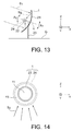
- FIG. 14 is an enlarged sectional view showing the structure of the conventional heat collector 1.
- the heat collecting pipe 22 is a pipe arranged in parallel with the horizontal axes of the reflecting mirrors 21.
- the sunrays S 1 are reflected by the reflecting mirrors 21 to become the reflected lights S 2 and the reflected lights S 2 are condensed to the heat collecting pipe 22.
- the heat medium 11 flows through the heat collecting pipe 22.
- the heat medium 11 flows in from one end of the heat collecting pipe 22 and flows out from the other end of the heat collecting pipe 22.
- the heat collecting pipe 22 is a metal pipe, for example.
- a space between the heat collecting pipe 22 and the glass pipe 24 is preferably a vacuum 13.
- air may exist between the heat collecting pipe 22 and the glass pipe 24 depending on a sealing structure between the heat collecting pipe 22 and the glass pipe 24.
- the heat medium 11, which is oil, for example, is heated by the condensed reflected lights S 2 .
- FIG. 15 is a schematic diagram showing a second example of the configuration of the conventional solar heat collecting system.
- descriptions on the components same as those in the first example are omitted.
- the solar heat collecting system in FIG. 15 includes a heat storage tank 7 instead of the heater 4.
- the solar heat collecting system in FIG. 15 further includes an on-off valve 8 that is provided with the heat utilizing fluid flow path 6 in the vicinity of the exit of the heat storage tank 7 in addition to the on-off valve 5 that is provided with the heat utilizing fluid flow path 6 in the vicinity of the entrance of the heat storage tank 7.
- the heat medium 11 in the heat medium flow path 3 is transferred by the pump 2 to flow into the heat collector 1.
- the heat medium 11 is heated by sunrays in the heat collector 1.
- the heated heat medium 11 flows out from the heat collector 1 into the heat storage tank 7 and heats a heat storable substance 14 in the heat storage tank 7 by heat exchange.
- the on-off valves 5 and 8 are closed and the heat utilizing fluid 12 does not circulate.
- the on-off valves 5 and 8 are opened.
- the heat utilizing fluid 12 in the heat utilizing fluid flow path 6 flows into the heat storage tank 7 and is heated by heat exchange with the heat storable substance 14.
- heat of the heat medium 11 in the present system is given to the heat utilizing fluid 12 via the heat storable substance 14.
- the heat utilizing fluid 12 flowing out from the heat storage tank 7 flows into a heat utilizing destination (not illustrated). Heat of the heat utilizing fluid 12 is utilized by the heat utilizing destination, the temperature of the heat utilizing fluid 12 decreases, and the heat utilizing fluid 12 flows out from the heat utilizing destination. At that time, the pump 2 stops and the heat medium 11 does not circulate.
- FIG. 16 is a schematic diagram showing a third example of the configuration of the conventional solar heat collecting system.
- descriptions on the components same as those in the first and second examples are omitted.
- the solar heat collecting system in FIG. 16 includes the heat storage tank 7 and the on-off valve 8. However, the heat storage tank 7 in FIG. 16 includes no heat storable substance 14.
- the heat medium 11 in the heat medium flow path 3 is transferred by the pump 2 to flow into the heat collector 1.
- the heat medium 11 is heated by sunrays in the heat collector 1.
- the heated heat medium 11 flows out from the heat collector 1 into the heat storage tank 7 and increases the temperature in the heat storage tank 7.
- the on-off valves 5 and 8 are closed and the heat utilizing fluid 12 does not circulate.
- the on-off valves 5 and 8 are opened.
- the heat utilizing fluid 12 in the heat utilizing fluid flow path 6 flows into the heat storage tank 7 and is heated by heat exchange with the heat medium 11 in the heat storage tank 7.
- the heat utilizing fluid 12 flowing out from the heat storage tank 7 flows into a heat utilizing destination (not illustrated). Heat of the heat utilizing fluid 12 is utilized by the heat utilizing destination, the temperature of the heat utilizing fluid 12 decreases, and the heat utilizing fluid 12 flows out from the heat utilizing destination. At that time, the pump 2 stops and the heat medium 11 does not circulate.
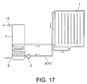
- FIG. 17 is a schematic diagram illustrating a fourth example of the configuration of the conventional solar heat collecting system.
- descriptions on the components same as those in the first to third examples are omitted.
- the heat collector 1 in FIG. 17 is a non-condensation type and does not track the sun.
- the solar heat collecting system in FIG. 17 is a hot water supply system with the heat collector 1 installed on a rooftop of a house.
- the heat medium 11 in the heat medium flow path 3 is transferred by the pump 2 to flow into the heat collector 1.
- the heat medium 11 is antifreeze, for example.
- the heat medium 11 is heated by sunrays in the heat collector 1.
- the heated heat medium 11 flows out from the heat collector 1 into the heat storage tank 7 and heats the heat utilizing fluid 12 in the heat storage tank 7 by heat exchange.
- the on-off valves 5 and 8 (not illustrated) are closed and the heat utilizing fluid 12 does not circulate.
- the heat utilizing fluid 12 is water, for example.
- the on-off valves 5 and 8 are opened.
- the heat utilizing fluid 12 in the heat storage tank 7 flows out from the heat storage tank 7 into a heat utilizing destination (not illustrated).
- Heat of the heat utilizing fluid 12 is utilized by the heat utilizing destination, the temperature of the heat utilizing fluid 12 decreases, and the heat utilizing fluid 12 flows out from the heat utilizing destination.
- the pump 2 stops and the heat medium 11 does not circulate.
- FIGS. 18A and 18B are graphs showing a first example of an amount of direct solar radiation and an amount of collected heat in the conventional solar heat collecting system.
- FIG. 18A shows an example of change in the amount of direct solar radiation with time in the vicinity of the heat collector 1.
- the amount of direct solar radiation is an amount of heat received per unit time and per unit area by a plane whose normal line is parallel to an incident direction of sunrays.
- FIG. 18B shows change in the amount of collected heat by the heat collector 1 with time with respect to the amount of direct solar radiation in FIG. 18A .
- the amount of collected heat in FIG. 18B shows the amount of collected heat that the heat medium 11 in the vicinity of the exit of the heat collector 1 has collected from the entrance to the exit of the heat collector 1 from sunrays.
- change in incident angles of sunrays to the heat collector 1 can be ignored.
- the sun is behind a cloud from time t 1 to time t 3 , and the sun appears from a cloud before time t 1 and after time t 3 .
- Time t 2 is a time between time t 1 to time t 3 .
- Time t 4 is a time after time t 3 .
- the amount of collected heat by the heat collector 1 is a value obtained by subtracting an amount of radiation from the heat collector 1 to the air from an amount of received heat from sunrays. In a time period when the amount of collected heat is a negative value, the amount of direct solar radiation and the amount of received heat are zero but the amount of radiation is not zero. As a result, the amount of collected heat in this time is negative.
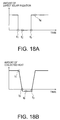
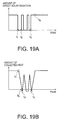
- FIGS. 19A and 19B are graphs showing a second example of the amount of direct solar radiation and the amount of collected heat in the conventional solar heat collecting system.
- FIG. 19A shows an example of change in the amount of direct solar radiation with time in the vicinity of the heat collector 1.
- FIG. 19B shows change in the amount of collected heat by the heat collector 1 with time with respect to the amount of direct solar radiation in FIG. 19A .
- the sun repeatedly appears from a cloud and disappears behind a cloud from time t 1 to time t 3 .
- the sun is behind a cloud from time t 1 to time t 2 and appears from the cloud again at time t 2 .
- a time period in which the amount of direct solar radiation remains zero is shorter than that in FIG. 18A . Since the amount of direct solar radiation gently decreases, an integrated amount of collected heat is a positive value from time t 1 to time t 2 . This is repeated multiple times between time t 1 and time t 2 . Consequently, the integrated amount of collected heat from time t 1 to time t 3 is a positive value.
- FIGS. 20A and 20B are graphs showing a third example of the amount of direct solar radiation and the amount of collected heat in the conventional solar heat collecting system.
- FIG. 20A shows an example of change in the amount of direct solar radiation with time in the vicinity of the heat collector 1.
- FIG. 20B shows change in the amount of collected heat by the heat collector 1 with time with respect to the amount of direct solar radiation in FIG. 20A .
- FIG. 20A the sun repeatedly appears from a cloud and disappears behind a cloud from time t 1 to time t 3 .
- the repetition frequency of the appearance and disappearance is higher than that in FIG. 19A .
- a time period in which the amount of direct solar radiation remains zero is shorter than those in FIGS. 18A and 19A .
- the amount of collected heat is smaller than that before time t 1 but does not reach a negative value.
- the solar heat collecting system includes the heat storage tank 7 as in FIGS. 15 to 17 , variation in the amount of collected heat is large in a view point of a time or a variation width but variation in the amount of heat to heat the heat utilizing fluid 12 in the storage tank 7 is small and is generally kept not to reach a negative value.
- a time period in which the amount of collected heat is a negative value no heat is supplied to the heat storage tank 7, and further, heat is radiated from the surface of the heat collector 1 to the air. Accordingly, as such a time period is longer, the amount of stored heat in the heat storage tank 7 from sunrise to sunset decreases. Further, power consumed by the pump 2 in this period is wasted. As such a time period in the solar heat collecting system is longer, the amount of acquired energy in the solar heat collecting system considerably decreases.
- FIGS. 1 to 10 components same as or similar to those in FIGS. 11 to 20 are denoted by same reference characters as those in FIGS. 11 to 20 , and descriptions overlapping with those in FIGS. 11 to 20 are omitted.
- a solar heat collecting system includes a heat collector configured to heat a heat medium by a sunray, a heating device configured to heat a heat utilizing fluid by heat of the heat medium, and a heat medium flow path configured to circulate the heat medium between the heat collector and the heating device.
- the system further includes a controller configured to control circulation of the heat medium in the heat collector in accordance with an amount of solar radiation of the sunray, or in accordance with a temperature difference between a first temperature of the heat medium at a first position and a second temperature of the heat medium at a second position located downstream of the first position with respect to the heat medium.
- FIG. 1 is a schematic view showing a configuration of a solar heat collecting system of a first embodiment.
- the solar heat collecting system in FIG. 1 includes the heat collector 1, the pump 2, the heat medium flow path 3, the on-off valve 5, the heat utilizing fluid flow path 6, the heat storage tank 7 and the on-off valve 8.
- the storage tank 7 in the present embodiment corresponds to the storage tank 7 in FIG. 16 .
- the storage tank 7 in the present embodiment may be replaced with the heater 4 in FIG. 11 , the heat storage tank 7 in FIG. 15 , or the heat storage tank 7 in FIG. 17 .
- Each of the heater 4 and the heat storage tanks 7 is an example of a heating device.
- the heat collector 1 in the present embodiment may be a condensation type or may be a non-condensation type.
- the heat collector 1 in the present embodiment is a trough type, for example.
- the solar heat collecting system in FIG. 1 further includes a direct solar radiation meter 31 and a controller 32.
- the direct solar radiation meter 31 is arranged at a position at which the amount of direct solar radiation from sunrays can be measured, for example, at a position in the vicinity of the heat collector 1.
- the direct solar radiation meter 31 measures the amount of direct solar radiation from sunrays and transmits the measurement result of the amount of direct solar radiation to the controller 32.
- the controller 32 controls circulation of the heat medium 11 in the heat collector 1 in accordance with the amount of direct solar radiation received from the direct solar radiation meter 31. For example, the controller 32 controls stop of the circulation of the heat medium 11, restart of the circulation of the heat medium 11, adjustment of the flow rate of the heat medium 11 and the like.
- the controller 32 in the present embodiment can control the circulation of the heat medium 11 by controlling the on/off and operation speed of the pump 2.
- the controller 32 may further control operations of the heat collector 1, the heat storage tank 7, the on-off valves 5 and 8 and the like.
- the controller 32 continuously monitors an amount of direct solar radiation using the direct solar radiation meter 31 and periodically compares the amount of direct solar radiation with a predetermined value that is determined in advance.
- the predetermined value is stored in a memory or storage of the controller 32, for example.
- the predetermined value is 0 W/m 2 or a value close to 0 W/m 2 , for example.
- the controller 32 continues the operation of the pump 2. Thereby, circulation of the heat medium 11 in the heat collector 1 continues.
- the controller 32 stops the pump 2. Thereby, circulation of the heat medium 11 in the heat collector 1 stops.
- the controller 32 may continue circulation of the heat medium 11 or may stop circulation of the heat medium 11. However, in the case where the predetermined value is set to 0 W/m 2 , when the amount of direct solar radiation is equal to the predetermined value, circulation of the heat medium 11 stops. In this case, circulation of the heat medium 11 is continued when the amount of direct solar radiation is not 0 W/m 2 , circulation of the heat medium 11 stops when the amount of direct solar radiation is 0 W/m 2 .
- the controller 32 stops the pump 2 to stop circulation of the heat medium 11 in the heat collector 1. Subsequently, the controller 32 continues to monitor the amount of direct solar radiation.
- the controller 32 keeps the pump 2 stopped. Thereby, stop of circulation of the heat medium 11 continues.
- the controller 32 restarts the operation of the pump 2. Thereby, circulation of the heat medium 11 in the heat collector 1 restarts.
- the predetermined value for restarting the operation of the pump 2 is same as the predetermined value for stopping the pump 2. However, these values may differ from each other.
- FIG. 2A and 2B are graphs showing an example of the amount of direct solar radiation and an amount of acquired heat in the solar heat collecting system of the first embodiment.
- FIG. 2A shows an example of change in the amount of direct solar radiation measured by the direct solar radiation meter 31 with time.
- a solid line in FIG. 2B shows change in the amount of acquired heat by the heat collector 1 with time with respect to the amount of direct solar radiation in FIG. 2A .
- the amount of acquired heat in FIG. 2B shows the amount of heat transferred to the exit of the heat collector 1, based on the assumption that the heat medium 11 in the heat collector 1 circulates.
- the total amount of acquired heat by the heat medium 11 is identical with the total amount of heat collected by the heat medium 11 in the heat collector 1 (shown by a dotted line in FIG. 2B ).
- the amount of direct solar radiation in FIG. 2A decreases to 0 W/m 2 at time t 1 . Accordingly, when the predetermined value is 0 W/m 2 , the pump 2 stops at time t 1 . Thereafter the pump 2 is kept stopped until time t 3 . On the other hand, the amount of direct solar radiation in FIG. 2A increases from 0 W/m 2 at time t 3 . Accordingly, the operation of the pump 2 restarts at time t 3 .
- the amount of direct solar radiation becomes zero
- the amount of received heat by the heat collector 1 decreases to zero.
- the heat collector 1 radiates heat even when the amount of received heat by the heat collector 1 becomes zero. Accordingly, when the amount of direct solar radiation becomes zero, the amount of acquired heat by the heat collector 1 becomes a negative value, as shown in FIG. 2B .
- the amount of direct solar radiation becomes zero at time t 1 so that the amount of acquired heat by the heat collector 1 is a negative value after time t 5 .
- the absolute value of the negative value in FIG. 2B is smaller than that in FIG. 18B .
- the reason for this is that the pump 2 stops when the amount of direct solar radiation becomes zero in the present embodiment. Since the heat medium 11 is not transferred during stop of the pump 2, the amount of heat carried out from the heat collector 1 by the heat medium 11 is zero (for this reason, the amount of collected heat during stop of the pump 2 is zero). Accordingly, the absolute value of the negative value in FIG. 2B is smaller than that in FIG. 18B (the more detailed reason will be given later). Therefore, according to the present embodiment, an amount of wasted radiation from the heat collector 1 when the amount of direct solar radiation is zero can be reduced.
- the pump 2 when the amount of direct solar radiation becomes zero, the pump 2 is stopped. If the pump 2 continues to operate after the amount of direct solar radiation becomes zero, the pump 2 operates even in a period when the amount of collected heat is a negative value. In this case, no energy can be acquired from sunrays in this period but the operation of the pump 2 consumes power. Accordingly, wasteful consumption of energy becomes large and the amount of acquired energy in the system considerably decreases. However, according to the present embodiment, when the amount of direct solar radiation becomes zero, the pump 2 is stopped. Accordingly, such wasteful consumption of energy can be reduced and decrease in the amount of acquired energy in the system can be suppressed.
- Circulation of the heat medium 11 may be stopped by a method other than stop of the pump 2.
- circulation of the heat medium 11 may be stopped by fully closing an on-off valve (not illustrated) provided with the heat medium flow path 3. In this case, when this on-off valve is opened, circulation of the heat medium 11 can restart.
- the controller 32 controls the operation of this on-off valve.
- circulation of the heat medium 11 in the heat collector 1 is controlled in accordance with the amount of solar radiation from sunrays. Therefore, according to the present embodiment, decrease in the amount of acquired energy in the solar heat collecting system caused by variation in the amount of collected heat by the heat collector 1 can be suppressed.
- FIG. 3 is a schematic view showing a configuration of a solar heat collecting system of a second embodiment.
- the solar heat collecting system in FIG. 3 includes thermometers 33 and 34 in addition to the components in FIG. 1 .
- illustration of the direct solar radiation meter 31, the pump 2, the on-off valve 5, the heat utilizing fluid flow path 6, the heat storage tank 7 and the on-off valve 8 is omitted.
- the thermometer 33 is arranged on the heat medium flow path 3 in the vicinity of the entrance of the heat collector 1 and measures the temperature (an entrance temperature) of the heat medium 11 at the entrance of the heat collector 1.
- the entrance of the heat collector 1 is an example of a first position.
- the entrance temperature of the heat collector 1 is an example of a first temperature.
- the thermometer 33 transmits the measurement result of the entrance temperature of the heat collector 1 to the controller 32.
- the thermometer 34 is arranged on the heat medium flow path 3 in the vicinity of the exit of the heat collector 1 and measures the temperature (an exit temperature) of the heat medium 11 at the exit of the heat collector 1.
- the exit of the heat collector 1 is an example of a second position located downstream of the first position with respect to the heat medium.
- the exit temperature of the heat collector 1 is an example of a second temperature.
- the thermometer 34 transmits the measurement result of the exit temperature of the heat collector 1 to the controller 32.
- the controller 32 controls circulation of the heat medium 11 in the heat collector 1 in accordance with a temperature difference between the entrance temperature received from the thermometer 33 and the exit temperature received from the thermometer 34. More specifically, when the pump 2 operates and the heat medium 11 circulates in the heat collector 1, the controller 32 stops the pump 2 in accordance with the temperature difference to stop circulation of the heat medium 11.
- the temperature difference is a value obtained by subtracting the entrance temperature from the exit temperature. When the temperature of the heat medium 11 increases in the heat collector 1, the temperature difference is positive. When the temperature of the heat medium 11 decreases in the heat collector 1, the temperature difference is negative.
- the controller 32 controls circulation of the heat medium 11 in the heat collector 1 in accordance with the amount of direct solar radiation received from the direct solar radiation meter 31. More specifically, when the pump 2 stops and circulation of the heat medium 11 stops, the controller 32 restarts the operation of the pump 2 in accordance with the amount of direct solar radiation to restart circulation of the heat medium 11.
- the controller 32 continuously monitors the above temperature difference using the thermometers 33 and 34 and periodically compares the temperature difference with a predetermined value (a first predetermined value) that is determined in advance.
- the first predetermined difference is stored in the memory or storage of the controller 32, for example.
- the first predetermined value is 0°C or a value close to 0°C, for example.
- the comparison result between the temperature difference and the first predetermined value indicates whether the temperature of the heat medium 11 increases or decreases in the heat collector 1.
- the controller 32 continuously monitors the amount of direct solar radiation using the direct solar radiation meter 31 and periodically compares the amount of direct solar radiation with a predetermined value (a second predetermined value). Similarly to the first predetermined value, the second predetermined value is stored in the memory or storage of the controller 32, for example.
- the second predetermined value is 0 W/m 2 or a value close to 0 W/m 2 , for example.
- the controller 32 continues the operation of the pump 2. Thereby, circulation of the heat medium 11 in the heat collector 1 continues.
- the controller 32 stops the pump 2. Thereby, circulation of the heat medium 11 in the heat collector 1 stops.
- the controller 32 may continue circulation of the heat medium 11 or may stop circulation of the heat medium 11.
- the controller 32 stops the pump 2 to stop circulation of the heat medium 11 in the heat collector 1.
- the amount of collected heat by the heat collector 1 is generally proportional to the temperature difference. For this reason, at a time when the temperature difference is 0°C, the amount of collected heat is zero. Time t 5 in FIGS. 2A and 2B is an example of such a time.
- the pump 2 stops at time t 1 at which the amount of direct solar radiation becomes 0 W/m 2 .
- the pump 2 stops at time t 5 at which the temperature difference becomes 0°C and the amount of collected heat becomes zero.
- the controller 32 keeps the pump 2 stopped. Thereby, circulation of the heat medium 11 is kept stopped.
- the controller 32 restarts the operation of the pump 2. Thereby, circulation of the heat medium 11 in the heat collector 1 restarts.
- the temperature difference is used for determination to stop the pump 2 and the amount of direct solar radiation is used for determination to restart the operation of the pump 2.
- the reason for this is that when the pump 2 stops, the amount of collected heat from sunrays cannot be evaluated from the temperature difference.
- circulation of the heat medium 11 in the heat collector 1 is controlled in accordance with the temperature difference between an entrance temperature and an exit temperature. Therefore, according to the present embodiment, as in the first embodiment, decrease in the amount of acquired energy in the solar heat collecting system caused by variation in the amount of collected heat by the heat collector 1 can be suppressed.
- the amount of direct solar radiation in FIG. 20A becomes zero multiple times while the amount of collected heat in FIG. 20B is kept positive.
- the pump 2 stops at these times if the solar heat collecting system is that of the first embodiment.
- the stop and restart of the pump 2 are repeated at short intervals. If the stop and restart are repeated many times every day, the unfavorable serious deterioration of the pump 2 is caused.
- the pump 2 does not stop even at these times. This is the advantage of the second embodiment.
- the first embodiment has an advantage that a time lag (for example, a time lag between time t 1 and time t 3 ) until the amount of direct solar radiation influences the temperature difference can be prevented from having an influence on control of circulation of the heat medium 11.
- a time lag for example, a time lag between time t 1 and time t 3
- FIG. 4 is a schematic view showing a configuration of a solar heat collecting system of a third embodiment.
- the solar heat collecting system in FIG. 4 includes thermometers 35 and 36 in addition to the components in FIG. 3 .
- illustration of the direct solar radiation meter 31, the pump 2, the on-off valve 5, the heat utilizing fluid flow path 6, the heat storage tank 7 and the on-off valve 8 is omitted.
- the heat collector 1 in the present embodiment includes first to third heat collecting modules (heat collecting units) 1a to 1c.
- the first heat collecting module 1a and the second heat collecting module 1b are arranged in parallel with each other with respect to the heat medium 11.
- the third heat collecting module 1c is arranged in series with the first and second heat collecting modules 1a and 1b with respect to the heat medium 11.
- Each of the first to third heat collecting modules 1a to 1c in the present embodiment has a same structure as the heat collector 1 illustrated in FIGS. 12 and 13 .
- the first to third heat collecting modules 1a to 1c are connected with one another via the heat medium flow path 3.
- the heat medium flow path 3 includes a first flow path 3a provided with the first heat collecting module 1a, a second flow path 3b provided with the second heat collecting module 1b, and a third flow path 3c provided with the third heat collecting module 1c.
- the heat medium flow path 3 braches off into the first and second flow paths 3a and 3b.
- the first and second flow paths 3a and 3b join to the third flow path 3c.
- the thermometer 35 is arranged on the first flow path 3a in the vicinity of the exit of the first heat collecting module 1a and measures the temperature (a first exit temperature) of the heat medium 11 at the exit of the first heat collecting module 1a.
- the thermometer 35 transmits the measurement result of the first exit temperature to the controller 32.
- the temperature (a first entrance temperature) of the heat medium 11 at the entrance of the heat collecting module 1a is measured by the thermometer 33.
- the first entrance temperature corresponds to the entrance temperature of the heat collector 1.
- the thermometer 36 is arranged on the third flow path 3c in the vicinity of the entrance of the third heat collecting module 1c and measures the temperature (a third entrance temperature) of the heat medium 11 at the entrance of the third heat collecting module 1c.
- the thermometer 36 transmits the measurement result of the third entrance temperature to the controller 32.
- the temperature (a third exit temperature) of the heat medium 11 at the exit of the third heat collecting module 1c is measured by the thermometer 34.
- the third exit temperature corresponds to the exit temperature of the heat collector 1.
- the controller 32 controls circulation of the heat medium 11 in the heat collector 1 in accordance with the temperature difference between the entrance temperature received from the thermometer 33 and the exit temperature received from the thermometer 34. More specifically, when the pump 2 operates and the heat medium 11 circulates in the heat collector 1, the controller 32 stops the pump 2 in accordance with this temperature difference to stop circulation of the heat medium 11.
- the controller 32 controls circulation of the heat medium 11 in the heat collector 1 in accordance with the temperature difference between the first entrance temperature from the thermometer 33 and the first exit temperature from the thermometer 35. In still another embodiment, the controller 32 controls circulation of the heat medium 11 in the heat collector 1 in accordance with the temperature difference between the third entrance temperature from the thermometer 36 and the third exit temperature from the thermometer 34. In these cases, a method of calculating the temperature difference and a method of setting the first predetermined value may be same as that used when the entrance temperature from the thermometer 33 and the exit temperature from the thermometer 34 are used.
- the controller 32 controls circulation of the heat medium 11 in the heat collector 1 in accordance with the amount of direct solar radiation received from the direct solar radiation meter 31. More specifically, when the pump 2 stops and circulation of the heat medium 11 stops, the controller 32 restarts the operation of the pump 2 in accordance with the amount of direct solar radiation to restart circulation of the heat medium 11.
- the number of the heat collecting modules 1a to 1c in the heat collector 1 in FIG. 4 is three. However, the number may be two, four or more.
- a solar heat collecting system of a fourth embodiment has a configuration illustrated in FIG. 4 .
- the controller 32 in the present embodiment stops circulation of the heat medium 11 in accordance with the temperature difference between the entrance temperature received from the thermometer 33 and the exit temperature received from the thermometer 34.
- the exit temperature from the thermometer 34 may be replaced with the first exit temperature from the thermometer 35.
- the entrance temperature from the thermometer 33 may be replaced with the third entrance temperature from the thermometer 36.
- the controller 32 in the present embodiment restarts circulation of the heat medium 11 in accordance with the amount of direct solar radiation from the direct solar radiation meter 31.
- the above operations are same as those in the third embodiment.
- the controller 32 in the present embodiment continues the operation of the pump 2 as long as a time period in which the temperature difference is smaller than the first predetermined value shorter than predetermined time.
- the controller 32 stops the pump 2. Thereby, circulation of the heat medium 11 in the heat collector 1 stops.
- the controller 32 may continue circulation of the heat medium 11 or may stop circulation of the heat medium 11.
- the predetermined time is stored in the memory or storage of the heat controller 32, for example, similarly to in the first and second predetermined values.
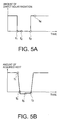
- FIGS. 5A and 5B are graphs showing an example of the amount of direct solar radiation and the amount of acquired heat in the solar heat collecting system of the fourth embodiment.
- FIG. 5A shows an example of change in the amount of direct solar radiation measured by the direct solar radiation meter 31 with time.
- FIG. 5B shows change in the amount of acquired heat by the heat collector 1 with time with respect to the amount of direct solar radiation in FIG. 5A .
- the stop and restart of the pump 2 are repeated multiple times.
- the stop and restart of the pump 2 are repeated multiple times. This is generally undesirable for the pump 2.
- the stop and restart of the pump 2 are repeated multiple times.
- a solar heat collecting system of a fifth embodiment has a configuration illustrated in FIG. 4 .
- the controller 32 in the present embodiment stops circulation of the heat medium 11 in accordance with the temperature difference between the entrance temperature received from the thermometer 33 and the exit temperature received from the thermometer 34.
- the exit temperature from the thermometer 34 may be replaced with the first exit temperature from the thermometer 35.
- the entrance temperature from the thermometer 33 may be replaced with the third entrance temperature from the thermometer 36.
- the controller 32 in the present embodiment restarts circulation of the heat medium 11 in accordance with the amount of direct solar radiation from the direct solar radiation meter 31.
- the above operations are same as those in the third and fourth embodiments.
- the controller 32 in the present embodiment keeps the pump 2 stopped as long as a time period in which the amount of direct solar radiation is larger than the second predetermined value is shorter than predetermined time.
- the controller 32 restarts the operation of the pump 2.
- circulation of the heat medium 11 in the heat collector 1 restarts.
- the controller 32 may keep circulation of the heat medium 11 stopped or may restart circulation of the heat medium 11.
- the predetermined time is stored in the memory or storage of the controller 32, for example.
- the value of the predetermined time for restarting circulation may be same as or may be different from the predetermined time for stopping circulation.
- the method of restarting circulation in the fifth embodiment can be combined with the method of stopping circulation in the first or second embodiment.
- FIG. 6 is a schematic view showing a configuration of a solar heat collecting system of a sixth embodiment.
- the solar heat collecting system in FIG. 6 has a configuration that is obtained by eliminating the third heat collecting module 1c, the third flow path 3c, and the thermometers 33, 34, and 36 from the system in FIG. 4 and adding a thermometer 37 and on-off valves 41 and 42 thereto.
- the first heat collecting module 1a and the second heat collecting module 1b are arranged in parallel with each other with respect to the heat medium 11.
- the thermometer 37 is arranged on the first flow path 3a in the vicinity of the entrance of the first heat collecting module 1a and measures the temperature (the first entrance temperature) of the heat medium 11 at the entrance of the first heat collecting module 1a.
- the thermometer 37 transmits the measurement result of the first entrance temperature to the controller 32.
- the thermometer 35 is arranged on the first flow path 3a in the vicinity of the exit of the first heat collecting module 1a and measures the temperature (the first exit temperature) of the heat medium 11 at the exit of the first heat collecting module 1a.
- the thermometer 35 transmits the measurement result of the first exit temperature to the controller 32.
- the on-off valve 41 is arranged on the second flow path 3b upstream of the entrance of the second heat collecting module 1b.
- the on-off valve 42 is arranged on the second flow path 3b downstream of the exit of the second heat collecting module 1b.
- the on-off valves 41 and 42 are opened/closed under control by the controller 32.
- the on-off valves 41 and 42 are opened during the operation of the pump 2, the heat medium 11 circulates in the second heat collecting module 1b.
- the on-off valves 41 and 42 are closed during the operation of the pump 2, circulation of the heat medium 11 in the second heat collecting module 1b stops.
- the controller 32 controls circulation of the heat medium 11 in the heat collector 1 in accordance with the temperature difference between the first entrance temperature from the thermometer 37 and the first exit temperature from the thermometer 35. More specifically, in the case where the pump 2 operates and the heat medium 11 circulates in the heat collector 1, when the temperature difference is larger than the predetermined value, the controller 32 keeps the on-off valves 41 and 42 open. On the other hand, in the case where the pump 2 operates, when the temperature difference becomes smaller than the predetermined value, the controller 32 fully closes the on-off valves 41 and 42. As a result, circulation of the heat medium 11 in the first heat collecting module 1a is kept while circulation of the heat medium 11 in the second heat collecting module 1b stops. Accordingly, the amount of radiation from the heat collector 1 is reduced.
- the controller 32 closes the on-off valves 41 and 42 and reduces the flow rate in the pump 2.
- the flow rate of the heat medium 11 in the heat collector 1 after the on-off valves 41 and 42 are closed decreases from that before the on-off valves 41 and 42 are closed. Accordingly, the amount of radiation from the heat collector 1 is further reduced.
- the first heat collecting module 1a is an example of the first portion.
- the second heat collecting module 1b is an example of the second portion.
- the controller 32 keeps the on-off valve 41 and 42 closed.
- the controller 32 opens the on-off valves 41 and 42.
- the controller 32 opens the on-off valves 41 and 42 and increases the flow rate in the pump 2. For example, the controller 32 returns the flow rate in the pump 2 to a value before the on-off valves 41 and 42 are closed. As a result, the flow rate of the heat medium 11 in the heat collector 1 after the on-off valves 41 and 42 are opened increases from that before the on-off valves 41 and 42 are opened. This is also true in the seventh and eighth embodiments, which will be described later.
- stop and restart of circulation of the heat medium 11 in a part of the heat collector 1 and the flow rate of the heat medium 11 in the heat collector 1 are controlled in accordance with the temperature difference between the entrance temperature and the exit temperature. Accordingly, power consumption in the pump 2 can be reduced, and the amount of radiation can be also reduced.
- the solar heat collecting system in FIG. 6 does not include the direct solar radiation meter 31 and circulation of the heat medium 11 in both the first and second heat collecting modules 1a and 1b stops, the system has no criterion for determining restart of circulation of the heat medium 11.
- the temperature difference that is obtained by using the thermometers 35 and 37 serves as a criterion for determination. Consequently, even when the solar heat collecting system in FIG.
- restart of circulation of the heat medium 11 can be controlled in accordance with temperatures so that the direct solar radiation meter 31 can be omitted.
- circulation of the heat medium 11 is desired to be kept for the entire system in some cases. In this case, to reduce power consumption in the pump 2, it suffices that circulation of the heat medium 11 stops only in a part of the system. Even if the flow rate in the pump 2 is not reduced, it is possible to decrease the amount of radiation from the second heat collecting module 11b in which circulation of the heat medium 11 stops.
- the number of the heat collecting modules 1a and 1b of the heat collector 1 in FIG. 6 are two, but may be three or more.
- valves similar to the on-off valves 41 and 42 may be arranged at upstream and downstream sides of two or more heat collecting modules. Thereby, the controller 32 can control stop and restart of circulation of the heat medium 11 in the two or more heat collecting modules.
- a solar heat collecting system of the seventh embodiment has the configuration illustrated in FIG. 6 .
- the controller 32 in the present embodiment controls circulation of the heat medium 11 in the heat collector 1 in accordance with the temperature difference between the first entrance temperature from the thermometer 37 and the first exit temperature from the thermometer 35. More specifically, when the pump 2 operates and the heat medium 11 circulates in the heat collector 1, the controller 32 keeps the on-off valves 41 and 42 open as long as a time in which the temperature difference is smaller than the predetermined value is shorter than predetermined time. On the other hand, when the pump 2 operates and a time in which the temperature difference is smaller than the predetermined value lasts longer than the predetermined time, the controller 32 fully closes the on-off valves 41 and 42. As a result, while circulation of the heat medium 11 in the first heat collecting module 1a is kept, circulation of the heat medium 11 in the second heat collecting module 1b stops.
- the controller 32 keeps the on-off valves 41 and 42 closed as long as a time in which the temperature difference is larger than the predetermined value is shorter than predetermined time.
- the controller 32 opens the on-off valves 41 and 42.
- circulation of the heat medium 11 in the second heat collecting module 1b restarts and the heat medium 11 circulates in the first and second heat collecting modules 1a and 1b.
- the amount of direct solar radiation in FIG. 20A becomes zero multiple times while the amount of collected heat in FIG. 20B is kept positive.
- the pump 2 stops at these times if the solar heat collecting system is that of the first embodiment.
- the operation and stop of the pump 2 is replaced with opening and closing of the on-off valves 41 and 42 and the on-off valves 41 and 42 are closed at these times. Opening and closing of the on-off valves 41 and 42 are repeated at short intervals. If such opening and closing are repeated many times every day, the unfavorable serious deterioration of the on-off valves 41 and 42 is caused.
- the on-off valves 41 and 42 are still opened at these times. This is the advantage of the seventh embodiment.
- a solar heat collecting system of an eighth embodiment has the configuration illustrated in FIG. 6 .
- the controller 32 in the present embodiment controls circulation of the heat medium 11 in the heat collector 1 in accordance with the amount of direct solar radiation from the direct solar radiation meter 31. More specifically, when the pump 2 operates and the heat medium 11 circulates in the heat collector 1, the controller 32 keeps the on-off valves 41 and 42 open as long as a time in which the amount of direct solar radiation is smaller than the predetermined value is shorter than predetermined time. On the other hand, when the pump 2 operates and a time in which the amount of direct solar radiation is smaller than the predetermined value is longer than the predetermined time, the controller 32 fully closes the on-off valves 41 and 42. As a result, while circulation of the heat medium 11 in the first heat collecting module 1a is kept, circulation of the heat medium 11 in the second heat collecting module 1b stops.
- the controller 32 keeps the on-off valves 41 and 42 closed as long as a time period in which the amount of direct solar radiation is larger than the predetermined time is shorter than the predetermined time.
- the controller 32 opens the on-off valves 41 and 42.
- circulation of the heat medium 11 in the second heat collecting module 1b restarts and the heat medium 11 circulates in the first and second heat collecting modules 1a and 1b.
- the amount of acquired energy in the solar heat collecting system can be suppressed.
- the amount of direct solar radiation and the predetermined value may be compared to control circulation of the heat medium 11.
- circulation of the heat medium 11 is desired to be kept for the entire system in some cases. In this case, to reduce power consumption in the pump 2, it suffices that circulation of the heat medium 11 stops only in a part of the system. Even if the flow rate in the pump 2 is not reduced, it is possible to decrease the amount of radiation from the second heat collecting module 1b in which circulation of the heat medium 11 stops.
- the amount of direct solar radiation in FIG. 20A becomes zero multiple times while the amount of collected heat in FIG. 20B is kept positive.
- the pump 2 stops at these timings if the solar heat collecting system is that of the first embodiment.
- the operation and stop of the pump 2 is replaced with opening and closing of the on-off valves 41 and 42, and the on-off valves 41 and 42 are closed at these times. Opening and closing of the on-off valves 41 and 42 are repeated at short intervals. If such opening and closing are repeated many times every day, the unfavorable serious deterioration of the on-off valves 41 and 42 is caused.
- the on-off valves 41 and 42 are still opened at these times. This is the advantage of the eighth embodiment.
- FIG. 7 is a schematic view showing a configuration of a solar heat collecting system of a ninth embodiment.
- the solar heat collecting system in FIG. 7 has a configuration that is obtained by eliminating the second heat collecting module 1b and the thermometers 33 and 35 from the system in FIG. 4 and adding on-off valves 41 to 44 thereto.
- the first heat collecting module 1a and the third heat collecting module 1c are arranged in series with respect to the heat medium 11.
- the second flow path 3b in the present embodiment can be used as a bypass flow path in which the heat medium 11 flows to bypass the first heat collecting module 1a.
- the on-off valve 41 is arranged in the vicinity of the entrance of the second flow path 3b.
- the on-off valve 42 is arranged in the vicinity of the exit of the second flow path 3b.
- the on-off valve 43 is arranged on the first flow path 3a upstream of the entrance of the first heat collecting module 1a.
- the on-off valve 44 is arranged on the first flow path 3a downstream of the exit of the first heat collecting module 1a.
- the on-off valves 41 to 44 are opened/closed under control by the controller 32.
- the heat medium 11 circulates in the first and third heat collecting modules 1a and 1c.
- the on-off valves 41 and 42 are opened and the on-off valves 43 and 44 are closed during the operation of the pump 2
- circulation of the heat medium 11 in the first heat collecting module 1a stops and the heat medium 11 circulates only in the third heat collecting module 1c.
- the heat medium 11 bypasses the first heat collecting module 1a to circulate in the second flow path 3c.
- the controller 32 controls circulation of the heat medium 11 in the heat collector 1 in accordance with the temperature difference between the third entrance temperature from the thermometer 36 and the third exit temperature from the thermometer 34. More specifically, in the case where the pump 2 operates and the heat medium 11 circulates in the heat collector 1, when the temperature difference is larger than the predetermined value, the controller 32 keeps the on-off valves 41 and 42 open and fully closes the on-off valves 43 and 44. On the other hand, in the case where the pump 2 operates, when the temperature difference becomes smaller than the predetermined value, the controller 32 opens the on-off valves 41 and 42 and fully closes the on-off valves 43 and 44. As a result, while circulation of the heat medium 11 in the third heat collecting module 1c is kept, circulation of the heat medium 11 in the first heat collecting module 1a stops so that the amount of radiation from the heat collector 1 is reduced.
- the controller 32 closes the on-off valves 43 and 44 and reduces the flow rate in the pump 2.
- the flow rate of the heat medium 11 in the heat collector 1 after the on-off valves 43 and 44 are closed becomes lower than that before the on-off valves 43 and 44 are closed so that the amount of radiation from the heat collector 1 is further reduced.
- the third heat collecting module 1c is an example of the first portion.
- the first heat collecting module 1a is an example of the second portion.
- the controller 32 keeps the on-off valves 41 and 42 open and the on-off valves 43 and 44 fully closed.
- the controller 32 fully closes the on-off valves 41 and 42 and opens the on-off valves 43 and 44.
- circulation of the heat medium 11 in the first heat collecting module 1a restarts and the heat medium 11 circulates in the first and third heat collecting modules 1a and 1c. Since the on-off valves 41 and 42 are closed, use of the second flow path 3b is released.
- the controller 32 opens the on-off valves 43 and 44 and increases the flow rate in the pump 2.
- the flow rate in the pump 2 is returned to a value before the on-off valves 43 and 44 are closed.
- the flow rate of the heat medium 11 in the heat collector 1 after the on-off valves 43 and 44 are opened becomes higher than that before the on-off valves 43 and 44 are opened. This is also true in the tenth and eleventh embodiments, which will be described later.
- stop and restart of circulation of the heat medium 11 in a part of the heat collector 1 and the flow rate of the heat medium 11 in the heat collector 1 are controlled in accordance with the temperature difference between the entrance temperature and the exit temperature. Therefore, according to the present embodiment, decrease in the amount of acquired energy in the solar heat collecting system caused by variation in the amount of collected heat by the heat collector 1 can be suppressed.
- restart of circulation of the heat medium 11 can be controlled in accordance with temperatures so that the direct solar radiation meter 31 can be omitted.
- the number of the heat collecting modules 1a and 1c in FIG. 7 are two, but may be three or more.
- valves similar to the on-off valves 43 and 44 may be arranged at upstream and downstream sides of two or more heat collecting modules. Thereby, the controller 32 can control stop and restart of circulation of the heat medium 11 in the two or more heat collecting modules.
- circulation of the heat medium 11 is desired to be kept for the entire system in some cases. In this case, to reduce power consumption in the pump 2, it suffices that circulation of the heat medium 11 stops only in a part of the system. Even if the flow rate in the pump 2 is not reduced, it is possible to decrease the amount of radiation from the first heat collecting module 1a in which circulation of the heat medium 11 stops.
- a solar heat collecting system of a tenth embodiment has the configuration illustrated in FIG. 7 .
- the controller 32 in the present embodiment controls circulation of the heat medium 11 in the heat collector 1 in accordance with the temperature difference between the third entrance temperature from the thermometer 36 and the third exit temperature from the thermometer 34. More specifically, when the pump 2 operates and the heat medium 11 circulates in the heat collector 1, the controller 32 keeps the on-off valves 41 and 42 fully closed and the on-off valves 43 and 44 open as long as a time in which the temperature difference is smaller than the predetermined value is shorter than predetermined time. On the other hand, when the pump 2 operates and a time in which the temperature difference is smaller than the predetermined value lasts longer than the predetermined time, the controller 32 opens the on-off valves 41 and 42 and fully closes the on-off valves 43 and 44. As a result, while circulation of the heat medium 11 in the third heat collecting module 1c is kept, circulation of the heat medium 11 in the first heat collecting module 1a stops.
- the controller 32 keeps the on-off valves 41 and 42 open and the on-off valves 43 and 44 fully closed as long as a time period in which the temperature difference is larger than the predetermined value is shorter than predetermined time.
- the controller 32 fully closes the on-off valves 41 and 42 and opens the on-off valves 43 and 44.
- circulation of the heat medium 11 in the first heat collecting module 1a restarts and the heat medium 11 circulates in the first and third heat collecting modules 1a and 1c. Since the on-off valves 41 and 42 are closed, use of the second flow path 3b is released.
- circulation of the heat medium 11 is desired to be kept for the entire system in some cases. In this case, to reduce power consumption in the pump 2, it suffices that circulation of the heat medium 11 stops only in a part of the system. Even if the flow rate in the pump 2 is not reduced, it is possible to decrease the amount of radiation from the first heat collecting module 11a in which circulation of the heat medium 11 stops.
- the amount of direct solar radiation in FIG. 20A becomes zero multiple times while the amount of collected heat in FIG. 20B is kept positive.
- the pump 2 stops at these times if the solar heat collecting system is that of the first embodiment.
- the operation and stop of the pump 2 is replaced with opening and closing of the on-off valves 41 to 44 and the on-off valves 43 and 44 are closed at these times. Opening and closing of the on-off valves 41 to 44 are repeated at short intervals. If such opening and closing are repeated many times every day, the unfavorable serious deterioration of the on-off valves 41 to 44 is caused.
- the on-off valves 41 and 43 are still opened at these times. This is the advantage of the tenth embodiment.
- a solar heat collecting system of an eleventh embodiment has the configuration illustrated in FIG. 7 .
- the controller 32 in the present embodiment controls circulation of the heat medium 11 in the heat collector 1 in accordance with the amount of direct solar radiation from the direct solar radiation meter 31. More specifically, when the pump 2 operates and the heat medium 11 circulates in the heat collector 1, the controller 32 keeps the on-off valves 41 and 42 fully closed and keeps the on-off valves 43 and 44 open as long as a time period in which the amount of direct solar radiation is smaller than the predetermined value is shorter than predetermined time. On the other hand, when the pump 2 operates and a time period in which the amount of direct solar radiation is smaller than the predetermined value lasts longer than the predetermined time, the controller 32 opens the on-off valves 41 and 42 and fully closes the on-off valves 43 and 44. As a result, while circulation of the heat medium 11 in the third heat collecting module 1c is kept, circulation of the heat medium 11 in the first heat collecting module 1a stops.
- the controller 32 keeps the on-off valves 41 and 42 open and the on-off valves 43 and 44 fully closed as long as a time period in which the amount of direct solar radiation is larger than the predetermined value is shorter than the predetermined time.
- the controller 32 fully closes the on-off valves 41 and 42 and opens the on-off valves 43 and 44.
- the amount of acquired energy in the solar heat collecting system can be suppressed.
- the amount of direct solar radiation and the predetermined value may be compared to control circulation of the heat medium 11.
- circulation of the heat medium 11 is desired to be kept for the entire system in some cases. In this case, to reduce power consumption in the pump 2, it suffices that circulation of the heat medium 11 stops only in a part of the system. Even if the flow rate in the pump 2 is not reduced, it is possible to decrease the amount of radiation from the first heat collecting module 1a in which circulation of the heat medium 11 stops.
- the amount of direct solar radiation in FIG. 20A becomes zero multiple times while the amount of collected heat in FIG. 20B is kept positive.
- the pump 2 stops at these times if the solar heat collecting system is that of the first embodiment.
- the operation and stop of the pump 2 is replaced with opening and closing of the on-off valves 41 to 44 and the on-off valves 43 and 44 are closed at these times. Opening and closing of the on-off valves 41 to 44 are repeated at short intervals. If such opening and closing are repeated many times every day, the unfavorable serious deterioration of the on-off valves 41 to 44 is caused.
- the on-off valves 41 and 43 are still opened at these times. This is the advantage of the eleventh embodiment.
- the operation of the heat collector 1 in a twelfth embodiment will be described with reference to FIG. 13 .
- the heat collector 1 in the present embodiment is installed in the solar heat collecting system of any one of the first to eleventh embodiments. This is also true for the heat collector 1 in thirteenth to fifteenth embodiments, which will be described later.
- the heat collector 1 in the present embodiment When the heat medium 11 circulates in the heat collector 1, the heat collector 1 in the present embodiment operates to condense sunrays to the heat collecting pipe 22, as illustrated in FIG. 13 . Also when circulation of the heat medium 11 stops in all or part of the entire heat collector 1, the heat collector 1 in the present embodiment operates to condense sunrays to the heat collecting pipe 22. That is, the reflecting mirrors 21 in the present embodiment continues to rotate to adjust the focal point of sunrays to the heat collecting pipe 22 both when the heat medium 11 circulates and when circulation of the heat medium 11 stops. The heat collector 1 rotates the reflecting mirror 21 to track the altitude of the sun. Accordingly, sunrays can be condensed to the heat collecting pipe 22.
- the heat collector 1 even when circulation of the heat medium 11 stops, the heat collector 1 continues to condense lights. Consequently, when circulation of the heat medium 11 restarts, the heat collector 1 can restart to collect heat immediately.
- the heat collector 1 in the twelfth embodiment includes a plurality of heat collecting modules as in FIGS. 4 , 6 and 7 , control of rotation of the reflecting mirror 21 that has been described in the twelfth embodiment can be performed for each heat collecting module.
- FIG. 8 is a sectional view for explaining the operation of the heat collector 1 of a thirteenth embodiment.
- the heat collector 1 in the present embodiment When the heat medium 11 circulates in the heat collector 1, the heat collector 1 in the present embodiment operates to condense sunrays to the heat collecting pipe 22 (see FIG. 13 ). However, when circulation of the heat medium 11 stops in all or part of the heat collector 1, the heat collector 1 in the present embodiment operates not to condense sunrays to the heat collecting pipe 22, as illustrated in FIG. 8 . That is, circulation of the heat medium 11 stops, the reflecting mirror 21 in the present embodiment is rotated and moved to a position not to adjust the focal point of sunrays to the heat collecting pipe 22. When circulation of the heat medium 11 in the heat collector 1 restarts, the heat collector 1 in the present embodiment operates to restart condensation of sunrays to the heat collecting pipe 22.
- condensation of lights by the heat collector 1 is stopped during stop of circulation of the heat medium 11 so that deterioration of the heat medium 11 in the heat collecting pipe 22 caused by a high temperature can be prevented.
- the flow rate in the pump 2 may be sufficiently low or zero depending on the starting characteristic of the pump 2.
- the focal point of sunrays is adjusted to the heat collecting pipe 22
- the temperature of the heat medium 11 becomes locally high and the heat medium 11 in this local area is deteriorated.
- the focal point of sunrays is not adjusted to the heat collecting pipe 22 as in the present embodiment, such deterioration can be prevented.
- the operation of the present embodiment is efficient, for example, when the flow rate of the heat medium 11 is zero or low during stop of circulation of the heat medium 11 or after restart of circulation of the heat medium 11.
- the heat collector 1 in the thirteenth embodiment includes a plurality of heat collecting modules as in FIGS. 4 , 6 and 7 , control of rotation of the reflecting mirror 21 that has been described in the thirteenth embodiment can be performed for each heat collecting module.
- FIG. 9 is a sectional view for explaining the operation of the heat collector 1 of a fourteenth embodiment.
- the heat collector 1 in the present embodiment When circulation of the heat medium 11 stops in all or part of the heat collector 1, the heat collector 1 in the present embodiment turns the convex surface of the reflecting mirror 21 to the upstream side of a wind W and moves the reflecting mirror 21 to the upstream side of the wind W upstream of the heat collecting pipe 22. In FIG. 9 , since the wind W blows in the -X direction, the convex surface of the reflecting mirror 21 is directed to the +X direction.
- the heat collector 1 in the present embodiment rotates the reflecting mirror 21 to restart condensation of sunrays to the heat collecting pipe 22.
- the reflecting mirror 21 is an example of a light condensing panel.
- the heat collecting pipe 22 is an example of a portion where heat is collected by condensation of lights.
- the flow rate of the wind W (an air flow) blowing to the heat collecting pipe 22 can be reduced by the reflecting mirror 21. Therefore, according to the present embodiment, the forced-convection heat transfer coefficient from the heat collecting pipe 22 to the air can be reduced and the amount of radiation from the heat collecting pipe 22 can be reduced.
- the heat collector 1 in the fourteenth embodiment includes a plurality of heat collecting modules as in FIGS. 4 , 6 and 7 , control of rotation of the reflecting mirror 21 that has been described in the fourteenth embodiment can be performed for each heat collecting module.
- FIG. 10 is a sectional view for explaining the operation of the heat collector 1 of a fifth embodiment.
- the heat collector 1 in the present embodiment When circulation of the heat medium 11 stops in all or part of the heat collector 1, the heat collector 1 in the present embodiment turns the convex surface of the reflecting mirror 21 upward (to the +Z direction) and moves the reflecting mirror 21 to a position above the heat collecting pipe 22. When circulation of the heat medium 11 in the heat collector 1 restarts, the heat collector 1 in the present embodiment rotates the reflecting mirror 21 to restart condensation of sunrays to the heat collecting pipe 22.
- the amount of forced-convection heat transfer from the heat collecting pipe 22 to the air is small.
- the amount of natural-convection heat transfer from the heat collecting pipe 22 to the air is reduced, the amount of radiation from the heat collecting pipe 22 is reduced. Accordingly, in the present embodiment, the convex surface of the reflecting mirror 21 is turned upward to suppress the air flow directly above the heat collecting pipe 22. Therefore, according to the present embodiment, the amount of natural-convection heat transfer from the heat collecting pipe 22 to the air can be reduced and the amount of radiation from the heat collecting pipe 22 can be reduced.
- the heat collector 1 in the fifteenth embodiment includes a plurality of heat collecting modules as in FIGS. 4 , 6 and 7 , control of rotation of the reflecting mirror 21 that has been described in the fifteenth embodiment can be performed for each heat collecting module.
Landscapes
- Engineering & Computer Science (AREA)
- Physics & Mathematics (AREA)
- Life Sciences & Earth Sciences (AREA)
- Sustainable Development (AREA)
- Sustainable Energy (AREA)
- Thermal Sciences (AREA)
- Chemical & Material Sciences (AREA)
- Combustion & Propulsion (AREA)
- Mechanical Engineering (AREA)
- General Engineering & Computer Science (AREA)
- Heat-Pump Type And Storage Water Heaters (AREA)
- Engine Equipment That Uses Special Cycles (AREA)
Abstract
Description
- Embodiments described herein relate to a solar heat collecting system.
-
FIG. 11 is a schematic diagram showing a first example of a configuration of a conventional solar heat collecting system. - The solar heat collecting system in
FIG. 11 includes aheat collector 1, apump 2, a heatmedium flow path 3, a heater 4, an on-offvalve 5 and a heat utilizingfluid flow path 6, and collects solar heat from sunrays. Arrows X and Y indicate horizontal directions that are perpendicular to each other. An arrow Z indicates a vertical direction. - A
heat medium 11 in the heatmedium flow path 3 is transferred by thepump 2 to flow into theheat collector 1. Theheat medium 11 is heated by sunrays in theheat collector 1. The heatedheat medium 11 flows out from theheat collector 1 and flows into the heater 4 to heat aheat utilizing fluid 12 in the heater 4 by heat exchange. - The
heat utilizing fluid 12 flowing out from the heater 4 flows into a heat utilizing destination (not illustrated) through the heat utilizingfluid flow path 6. An example of the heat utilizing destination is a heat utilizing facility. For example, when the heat utilizing destination is a hot water supply facility, water as theheat utilizing fluid 12 is heated in the heater 4 and supplied as hot water. Another example of the heat utilizing destination is a power generation facility. For example, when the heat utilizing destination is a turbine power generation facility of a Rankine cycle, a turbine operating medium as theheat utilizing fluid 12 is heated in the heater 4. Another example of the heat utilizing destination is a water treatment facility. For example, when the heat utilizing destination is a seawater desalination facility, seawater as theheat utilizing fluid 12 is heated in the heater 4. - Heat of the
heat utilizing fluid 12 is utilized by the heat utilizing destination, so that the temperature of theheat utilizing fluid 12 decreases and theheat utilizing fluid 12 then flows out from the heat utilizing destination. In this way, theheat utilizing fluid 12 circulates between the heater 4 and the heat utilizing destination via the heat utilizingfluid flow path 6. The heat utilizingfluid flow path 6 is provided with the on-offvalve 5. On the other hand, heat of theheat medium 11 is utilized by the heater 4, so that the temperature of theheat medium 11 decreases and theheat medium 11 then flows out from the heater 4. In this way, theheat medium 11 circulates between theheat collector 1 and the heater 4 via the heatmedium flow path 3. -
FIGS. 12 and13 are a perspective view and a sectional view showing a structure of theconventional heat collector 1. - Types of the
heat collector 1 include a condensation type and a non-condensation type. Examples of the condensation-type heat collector 1 include a trough type, a Fresnel type and a tower type.FIGS. 12 and13 illustrate an example of the trough-type heat collector 1. - As illustrated in
FIG. 13 , theheat collector 1 includes a reflectingmirror 21, aheat collecting pipe 22, asupport 23 and aglass pipe 24, and is provided on the ground G. - The reflecting
mirror 21 has a curved shape that is long in a horizontal direction. A section perpendicular to the longitudinal direction of the reflectingmirror 21 is a parabola. Theheat collector 1 rotates and drives the reflectingmirror 21 so as to make an axis K (a straight line connecting a focal point and an apex) of the parabola parallel to the sunrays S1. That is, thereflecting mirror 21 tracks the sun according to the altitude of the sun. Reference character S2 denotes a reflected light of sunray S1 reflected by thereflecting mirror 21. - The
heat collecting pipe 22 is arranged at the focal point of the parabola. Theheat collector 1 may adjust the rotation center of the reflectingmirror 21 to the focal point of the parabola or may adjust the rotation center of the reflectingmirror 21 to a point different from the focal point. InFIG. 13 , the rotation center is the end of thesupport 23 and the reflectingmirror 21 rotates in a direction of an arrow A1. The reflectingmirror 21 has a structure connected and integrated with theheat collecting pipe 22. Theheat collecting pipe 22 rotates in a direction of an arrow A2 in response to the rotation of the reflectingmirror 21 in the arrow A1. The rotation center of theheat collecting pipe 22 is same as that of the reflectingmirror 21. Accordingly, from a viewpoint of a phase in the peripheral direction of theheat collecting pipe 22, rotation of the reflectingmirror 21 has no influence in a surface area of theheat collecting pipe 22 that is nearest to the reflectingmirror 21. -
FIG. 14 is an enlarged sectional view showing the structure of theconventional heat collector 1. - The
heat collecting pipe 22 is a pipe arranged in parallel with the horizontal axes of the reflectingmirrors 21. The sunrays S1 are reflected by thereflecting mirrors 21 to become the reflected lights S2 and the reflected lights S2 are condensed to theheat collecting pipe 22. Theheat medium 11 flows through theheat collecting pipe 22. Theheat medium 11 flows in from one end of theheat collecting pipe 22 and flows out from the other end of theheat collecting pipe 22. - Only a portion of the
heat collecting pipe 22 where the reflected lights S2 are condensed is in thetransparent glass pipe 24. Theheat collecting pipe 22 is a metal pipe, for example. A space between theheat collecting pipe 22 and theglass pipe 24 is preferably avacuum 13. However, air may exist between theheat collecting pipe 22 and theglass pipe 24 depending on a sealing structure between theheat collecting pipe 22 and theglass pipe 24. Theheat medium 11, which is oil, for example, is heated by the condensed reflected lights S2. -
FIG. 15 is a schematic diagram showing a second example of the configuration of the conventional solar heat collecting system. In the descriptions onFIG. 15 , descriptions on the components same as those in the first example are omitted. - The solar heat collecting system in
FIG. 15 includes aheat storage tank 7 instead of the heater 4. The solar heat collecting system inFIG. 15 further includes an on-offvalve 8 that is provided with the heat utilizingfluid flow path 6 in the vicinity of the exit of theheat storage tank 7 in addition to the on-offvalve 5 that is provided with the heat utilizingfluid flow path 6 in the vicinity of the entrance of theheat storage tank 7. - During a heat storage operation, the
heat medium 11 in the heatmedium flow path 3 is transferred by thepump 2 to flow into theheat collector 1. Theheat medium 11 is heated by sunrays in theheat collector 1. The heatedheat medium 11 flows out from theheat collector 1 into theheat storage tank 7 and heats a heatstorable substance 14 in theheat storage tank 7 by heat exchange. At that time, the on-offvalves heat utilizing fluid 12 does not circulate. - During a heat utilizing operation, the on-off
valves heat utilizing fluid 12 in the heat utilizingfluid flow path 6 flows into theheat storage tank 7 and is heated by heat exchange with the heatstorable substance 14. In this way, heat of theheat medium 11 in the present system is given to theheat utilizing fluid 12 via the heatstorable substance 14. Theheat utilizing fluid 12 flowing out from theheat storage tank 7 flows into a heat utilizing destination (not illustrated). Heat of theheat utilizing fluid 12 is utilized by the heat utilizing destination, the temperature of theheat utilizing fluid 12 decreases, and theheat utilizing fluid 12 flows out from the heat utilizing destination. At that time, thepump 2 stops and theheat medium 11 does not circulate. -
FIG. 16 is a schematic diagram showing a third example of the configuration of the conventional solar heat collecting system. In the descriptions onFIG. 16 , descriptions on the components same as those in the first and second examples are omitted. - Similarly to the solar heat collecting system in
FIG. 15 , the solar heat collecting system inFIG. 16 includes theheat storage tank 7 and the on-offvalve 8. However, theheat storage tank 7 inFIG. 16 includes no heatstorable substance 14. - During a heat storage operation, the
heat medium 11 in the heatmedium flow path 3 is transferred by thepump 2 to flow into theheat collector 1. Theheat medium 11 is heated by sunrays in theheat collector 1. Theheated heat medium 11 flows out from theheat collector 1 into theheat storage tank 7 and increases the temperature in theheat storage tank 7. At that time, the on-offvalves heat utilizing fluid 12 does not circulate. - During a heat utilizing operation, the on-off
valves heat utilizing fluid 12 in the heat utilizingfluid flow path 6 flows into theheat storage tank 7 and is heated by heat exchange with theheat medium 11 in theheat storage tank 7. Theheat utilizing fluid 12 flowing out from theheat storage tank 7 flows into a heat utilizing destination (not illustrated). Heat of theheat utilizing fluid 12 is utilized by the heat utilizing destination, the temperature of theheat utilizing fluid 12 decreases, and theheat utilizing fluid 12 flows out from the heat utilizing destination. At that time, thepump 2 stops and theheat medium 11 does not circulate. -
FIG. 17 is a schematic diagram illustrating a fourth example of the configuration of the conventional solar heat collecting system. In the descriptions onFIG. 17 , descriptions on the components same as those in the first to third examples are omitted. - The
heat collector 1 inFIG. 17 is a non-condensation type and does not track the sun. The solar heat collecting system inFIG. 17 is a hot water supply system with theheat collector 1 installed on a rooftop of a house. - During a heat storage operation, the
heat medium 11 in the heatmedium flow path 3 is transferred by thepump 2 to flow into theheat collector 1. Theheat medium 11 is antifreeze, for example. Theheat medium 11 is heated by sunrays in theheat collector 1. Theheated heat medium 11 flows out from theheat collector 1 into theheat storage tank 7 and heats theheat utilizing fluid 12 in theheat storage tank 7 by heat exchange. At that time, the on-offvalves 5 and 8 (not illustrated) are closed and theheat utilizing fluid 12 does not circulate. Theheat utilizing fluid 12 is water, for example. - During a heat utilizing operation, the on-off
valves heat utilizing fluid 12 in theheat storage tank 7 flows out from theheat storage tank 7 into a heat utilizing destination (not illustrated). Heat of theheat utilizing fluid 12 is utilized by the heat utilizing destination, the temperature of theheat utilizing fluid 12 decreases, and theheat utilizing fluid 12 flows out from the heat utilizing destination. At that time, thepump 2 stops and theheat medium 11 does not circulate. -
-
FIG. 1 is a schematic view showing a configuration of a solar heat collecting system of a first embodiment; -
FIG. 2A and 2B are graphs showing an example of an amount of direct solar radiation and an amount of acquired heat in the solar heat collecting system of the first embodiment; -
FIG. 3 is a schematic view showing a configuration of a solar heat collecting system of a second embodiment; -
FIG. 4 is a schematic view showing a configuration of a solar heat collecting system of a third embodiment; -
FIGS. 5A and 5B are graphs showing an example of the amount of direct solar radiation and the amount of acquired heat in a solar heat collecting system of a fourth embodiment; -
FIG. 6 is a schematic view showing a configuration of a solar heat collecting system of a sixth embodiment; -
FIG. 7 is a schematic view showing a configuration of a solar heat collecting system of a ninth embodiment; -
FIG. 8 is a sectional view for explaining the operation of a heat collector of a thirteenth embodiment; -
FIG. 9 is a sectional view for explaining the operation of a heat collector of a fourteenth embodiment; -
FIG. 10 is a sectional view for explaining the operation of a heat collector of a fifth embodiment; -
FIG. 11 is a schematic diagram showing a first example of a configuration of a conventional solar heat collecting system; -
FIG. 12 is a perspective view showing a structure of a conventional heat collector; -
FIG. 13 is a sectional view showing the structure of the conventional heat collector; -
FIG. 14 is an enlarged sectional view showing the structure of the conventional heat collector; -
FIG. 15 is a schematic diagram showing a second example of the configuration of the conventional solar heat collecting system; -
FIG. 16 is a schematic diagram showing a third example of the configuration of the conventional solar heat collecting system; -
FIG. 17 is a schematic diagram showing a fourth example of the configuration of the conventional solar heat collecting system; -
FIGS. 18A and 18B are graphs showing a first example of the amount of direct solar radiation and an amount of collected heat in the conventional solar heat collecting system; -
FIGS. 19A and 19B are graphs showing a second example of the amount of direct solar radiation and the amount of collected heat in the conventional solar heat collecting system; and -
FIGS. 20A and 20B are graphs showing a third example of the amount of direct solar radiation and the amount of collected heat in the conventional solar heat collecting system. - Embodiments will now be explained with reference to the accompanying drawings.
-
FIGS. 18A and 18B are graphs showing a first example of an amount of direct solar radiation and an amount of collected heat in the conventional solar heat collecting system. -
FIG. 18A shows an example of change in the amount of direct solar radiation with time in the vicinity of theheat collector 1. The amount of direct solar radiation is an amount of heat received per unit time and per unit area by a plane whose normal line is parallel to an incident direction of sunrays. -
FIG. 18B shows change in the amount of collected heat by theheat collector 1 with time with respect to the amount of direct solar radiation inFIG. 18A . The amount of collected heat inFIG. 18B shows the amount of collected heat that theheat medium 11 in the vicinity of the exit of theheat collector 1 has collected from the entrance to the exit of theheat collector 1 from sunrays. During the time indicated by the abscissa inFIG. 18B , change in incident angles of sunrays to theheat collector 1 can be ignored. - In
FIG. 18A , the sun is behind a cloud from time t1 to time t3, and the sun appears from a cloud before time t1 and after time t3. Time t2 is a time between time t1 to time t3. Time t4 is a time after time t3. When the sun disappears behind a cloud at time t1, the amount of direct solar radiation drops suddenly to reach zero. When the sun appears from a cloud at time t3, the amount of direct solar radiation rises suddenly to return to the value before the time t1. - In
FIG. 18B , when the amount of direct solar radiation becomes zero at time t1, the amount of collected heat gently decreases to be a negative value from time t1. The reason why the amount of collected heat gently decreases is that theheat medium 11 flowing out from theheat collector 1 is heated by sunrays before time t1. Time t5 represents a time when the amount of collected heat reaches zero. Time t6 represents an example of a time when the amount of collected heat is a negative value. When the amount of direct solar radiation becomes a value other than zero at time t3, the amount of collected heat gently increases from time t3 to return to the value before time t1. The reason why the amount of collected heat gently increases is that theheat medium 11 flowing out from theheat collector 1 is not heated by sunrays before time t3. - The amount of collected heat by the
heat collector 1 is a value obtained by subtracting an amount of radiation from theheat collector 1 to the air from an amount of received heat from sunrays. In a time period when the amount of collected heat is a negative value, the amount of direct solar radiation and the amount of received heat are zero but the amount of radiation is not zero. As a result, the amount of collected heat in this time is negative. -
FIGS. 19A and 19B are graphs showing a second example of the amount of direct solar radiation and the amount of collected heat in the conventional solar heat collecting system.FIG. 19A shows an example of change in the amount of direct solar radiation with time in the vicinity of theheat collector 1.FIG. 19B shows change in the amount of collected heat by theheat collector 1 with time with respect to the amount of direct solar radiation inFIG. 19A . - In
FIG. 19A , the sun repeatedly appears from a cloud and disappears behind a cloud from time t1 to time t3. For example, the sun is behind a cloud from time t1 to time t2 and appears from the cloud again at time t2. Accordingly, a time period in which the amount of direct solar radiation remains zero is shorter than that inFIG. 18A . Since the amount of direct solar radiation gently decreases, an integrated amount of collected heat is a positive value from time t1 to time t2. This is repeated multiple times between time t1 and time t2. Consequently, the integrated amount of collected heat from time t1 to time t3 is a positive value. -
FIGS. 20A and 20B are graphs showing a third example of the amount of direct solar radiation and the amount of collected heat in the conventional solar heat collecting system.FIG. 20A shows an example of change in the amount of direct solar radiation with time in the vicinity of theheat collector 1.FIG. 20B shows change in the amount of collected heat by theheat collector 1 with time with respect to the amount of direct solar radiation inFIG. 20A . - In
FIG. 20A , the sun repeatedly appears from a cloud and disappears behind a cloud from time t1 to time t3. The repetition frequency of the appearance and disappearance is higher than that inFIG. 19A . A time period in which the amount of direct solar radiation remains zero is shorter than those inFIGS. 18A and19A . As a result, from time t1 to time t3, the amount of collected heat is smaller than that before time t1 but does not reach a negative value. - On the basis of the descriptions of
FIGS. 18A and 18B to 20A and 20B, an amount of direct solar radiation and an amount of collected heat in a conventional solar heat collecting system will be described. - In a time period in which the amount of collected heat by the
heat collector 1 is a negative value, the amount of radiation is larger than the amount of received heat. As such a time period is longer, an integrated amount of collected heat by theheat collector 1 from sunrise to sunset decreases. Further, power consumed by thepump 2 in this time period is wasted. Accordingly, as this time period in the solar heat collecting system is longer, an amount of acquired energy, which is obtained by subtracting an energy consumption amount from an energy amount acquired from sunrays, considerably decreases. - When the solar heat collecting system includes the
heat storage tank 7 as inFIGS. 15 to 17 , variation in the amount of collected heat is large in a view point of a time or a variation width but variation in the amount of heat to heat theheat utilizing fluid 12 in thestorage tank 7 is small and is generally kept not to reach a negative value. However, in a time period in which the amount of collected heat is a negative value, no heat is supplied to theheat storage tank 7, and further, heat is radiated from the surface of theheat collector 1 to the air. Accordingly, as such a time period is longer, the amount of stored heat in theheat storage tank 7 from sunrise to sunset decreases. Further, power consumed by thepump 2 in this period is wasted. As such a time period in the solar heat collecting system is longer, the amount of acquired energy in the solar heat collecting system considerably decreases. - In
FIGS. 1 to 10 , components same as or similar to those inFIGS. 11 to 20 are denoted by same reference characters as those inFIGS. 11 to 20 , and descriptions overlapping with those inFIGS. 11 to 20 are omitted. - In one embodiment, a solar heat collecting system includes a heat collector configured to heat a heat medium by a sunray, a heating device configured to heat a heat utilizing fluid by heat of the heat medium, and a heat medium flow path configured to circulate the heat medium between the heat collector and the heating device. The system further includes a controller configured to control circulation of the heat medium in the heat collector in accordance with an amount of solar radiation of the sunray, or in accordance with a temperature difference between a first temperature of the heat medium at a first position and a second temperature of the heat medium at a second position located downstream of the first position with respect to the heat medium.
-
FIG. 1 is a schematic view showing a configuration of a solar heat collecting system of a first embodiment. - Similarly to the system in
FIG. 16 , the solar heat collecting system inFIG. 1 includes theheat collector 1, thepump 2, the heatmedium flow path 3, the on-offvalve 5, the heat utilizingfluid flow path 6, theheat storage tank 7 and the on-offvalve 8. Thestorage tank 7 in the present embodiment corresponds to thestorage tank 7 inFIG. 16 . However, thestorage tank 7 in the present embodiment may be replaced with the heater 4 inFIG. 11 , theheat storage tank 7 inFIG. 15 , or theheat storage tank 7 inFIG. 17 . Each of the heater 4 and theheat storage tanks 7 is an example of a heating device. Theheat collector 1 in the present embodiment may be a condensation type or may be a non-condensation type. Theheat collector 1 in the present embodiment is a trough type, for example. The solar heat collecting system inFIG. 1 further includes a directsolar radiation meter 31 and acontroller 32. - The direct
solar radiation meter 31 is arranged at a position at which the amount of direct solar radiation from sunrays can be measured, for example, at a position in the vicinity of theheat collector 1. The directsolar radiation meter 31 measures the amount of direct solar radiation from sunrays and transmits the measurement result of the amount of direct solar radiation to thecontroller 32. - The
controller 32 controls circulation of theheat medium 11 in theheat collector 1 in accordance with the amount of direct solar radiation received from the directsolar radiation meter 31. For example, thecontroller 32 controls stop of the circulation of theheat medium 11, restart of the circulation of theheat medium 11, adjustment of the flow rate of theheat medium 11 and the like. Thecontroller 32 in the present embodiment can control the circulation of theheat medium 11 by controlling the on/off and operation speed of thepump 2. Thecontroller 32 may further control operations of theheat collector 1, theheat storage tank 7, the on-offvalves - Hereinafter, operations of the
controller 32 in the present embodiment will be described. - The
controller 32 continuously monitors an amount of direct solar radiation using the directsolar radiation meter 31 and periodically compares the amount of direct solar radiation with a predetermined value that is determined in advance. The predetermined value is stored in a memory or storage of thecontroller 32, for example. The predetermined value is 0 W/m2 or a value close to 0 W/m2, for example. - In the case where the
pump 2 operates and theheat medium 11 circulates in theheat collector 1, when the amount of direct solar heat is larger than the predetermined value, thecontroller 32 continues the operation of thepump 2. Thereby, circulation of theheat medium 11 in theheat collector 1 continues. On the other hand, in the case where thepump 2 operates and theheat medium 11 circulates in theheat collector 1, when the amount of direct solar heat becomes smaller than the predetermined value, thecontroller 32 stops thepump 2. Thereby, circulation of theheat medium 11 in theheat collector 1 stops. - When the amount of direct solar radiation is equal to the predetermined value, the
controller 32 may continue circulation of theheat medium 11 or may stop circulation of theheat medium 11. However, in the case where the predetermined value is set to 0 W/m2, when the amount of direct solar radiation is equal to the predetermined value, circulation of theheat medium 11 stops. In this case, circulation of theheat medium 11 is continued when the amount of direct solar radiation is not 0 W/m2, circulation of theheat medium 11 stops when the amount of direct solar radiation is 0 W/m2. - In this way, when the amount of direct solar radiation is smaller than the predetermined value, the
controller 32 stops thepump 2 to stop circulation of theheat medium 11 in theheat collector 1. Subsequently, thecontroller 32 continues to monitor the amount of direct solar radiation. - In the case where the
pump 2 stops and circulation of theheat medium 11 stops, when the amount of direct solar radiation is smaller than the predetermined value, thecontroller 32 keeps thepump 2 stopped. Thereby, stop of circulation of theheat medium 11 continues. On the other hand, in the case where thepump 2 stops and circulation of theheat medium 11 is stopped, when the amount of direct solar radiation becomes larger than the predetermined value, thecontroller 32 restarts the operation of thepump 2. Thereby, circulation of theheat medium 11 in theheat collector 1 restarts. - In the present embodiment, the predetermined value for restarting the operation of the
pump 2 is same as the predetermined value for stopping thepump 2. However, these values may differ from each other. -
FIG. 2A and 2B are graphs showing an example of the amount of direct solar radiation and an amount of acquired heat in the solar heat collecting system of the first embodiment.FIG. 2A shows an example of change in the amount of direct solar radiation measured by the directsolar radiation meter 31 with time. A solid line inFIG. 2B shows change in the amount of acquired heat by theheat collector 1 with time with respect to the amount of direct solar radiation inFIG. 2A . The amount of acquired heat inFIG. 2B shows the amount of heat transferred to the exit of theheat collector 1, based on the assumption that theheat medium 11 in theheat collector 1 circulates. The total amount of acquired heat by theheat medium 11 is identical with the total amount of heat collected by theheat medium 11 in the heat collector 1 (shown by a dotted line inFIG. 2B ). - The amount of direct solar radiation in
FIG. 2A decreases to 0 W/m2 at time t1. Accordingly, when the predetermined value is 0 W/m2, thepump 2 stops at time t1. Thereafter thepump 2 is kept stopped until time t3. On the other hand, the amount of direct solar radiation inFIG. 2A increases from 0 W/m2 at time t3. Accordingly, the operation of thepump 2 restarts at time t3. - When the amount of direct solar radiation becomes zero, the amount of received heat by the
heat collector 1 decreases to zero. However, theheat collector 1 radiates heat even when the amount of received heat by theheat collector 1 becomes zero. Accordingly, when the amount of direct solar radiation becomes zero, the amount of acquired heat by theheat collector 1 becomes a negative value, as shown inFIG. 2B . InFIG. 2B , the amount of direct solar radiation becomes zero at time t1 so that the amount of acquired heat by theheat collector 1 is a negative value after time t5. - The above phenomenon can be seen also in
FIG. 18B . However, the absolute value of the negative value inFIG. 2B is smaller than that inFIG. 18B . The reason for this is that thepump 2 stops when the amount of direct solar radiation becomes zero in the present embodiment. Since theheat medium 11 is not transferred during stop of thepump 2, the amount of heat carried out from theheat collector 1 by theheat medium 11 is zero (for this reason, the amount of collected heat during stop of thepump 2 is zero). Accordingly, the absolute value of the negative value inFIG. 2B is smaller than that inFIG. 18B (the more detailed reason will be given later). Therefore, according to the present embodiment, an amount of wasted radiation from theheat collector 1 when the amount of direct solar radiation is zero can be reduced. - In the present embodiment, when the amount of direct solar radiation becomes zero, the
pump 2 is stopped. If thepump 2 continues to operate after the amount of direct solar radiation becomes zero, thepump 2 operates even in a period when the amount of collected heat is a negative value. In this case, no energy can be acquired from sunrays in this period but the operation of thepump 2 consumes power. Accordingly, wasteful consumption of energy becomes large and the amount of acquired energy in the system considerably decreases. However, according to the present embodiment, when the amount of direct solar radiation becomes zero, thepump 2 is stopped. Accordingly, such wasteful consumption of energy can be reduced and decrease in the amount of acquired energy in the system can be suppressed. - When circulation of the
heat medium 11 stops, heat transfer between the inner wall surface of theheat collector 1 and theheat medium 11 is not forced-convection heat transfer and the heat transfer coefficient between the inner wall surface of theheat collector 1 and theheat medium 11 is reduced. Accordingly, when circulation of theheat medium 11 stops, an amount of radiation from theheat medium 11 to the air through theheat collector 1 is reduced. As a result, the amount of collected heat from sunrise to sunset increases. This also contributes to increase in the amount of acquired energy in the present embodiment. - Circulation of the
heat medium 11 may be stopped by a method other than stop of thepump 2. For example, circulation of theheat medium 11 may be stopped by fully closing an on-off valve (not illustrated) provided with the heatmedium flow path 3. In this case, when this on-off valve is opened, circulation of theheat medium 11 can restart. Thecontroller 32 controls the operation of this on-off valve. - As described above, in the present embodiment, circulation of the
heat medium 11 in theheat collector 1 is controlled in accordance with the amount of solar radiation from sunrays. Therefore, according to the present embodiment, decrease in the amount of acquired energy in the solar heat collecting system caused by variation in the amount of collected heat by theheat collector 1 can be suppressed. -
FIG. 3 is a schematic view showing a configuration of a solar heat collecting system of a second embodiment. - The solar heat collecting system in
FIG. 3 includesthermometers FIG. 1 . However, inFIG. 3 , illustration of the directsolar radiation meter 31, thepump 2, the on-offvalve 5, the heat utilizingfluid flow path 6, theheat storage tank 7 and the on-offvalve 8 is omitted. - The
thermometer 33 is arranged on the heatmedium flow path 3 in the vicinity of the entrance of theheat collector 1 and measures the temperature (an entrance temperature) of theheat medium 11 at the entrance of theheat collector 1. The entrance of theheat collector 1 is an example of a first position. The entrance temperature of theheat collector 1 is an example of a first temperature. Thethermometer 33 transmits the measurement result of the entrance temperature of theheat collector 1 to thecontroller 32. - The
thermometer 34 is arranged on the heatmedium flow path 3 in the vicinity of the exit of theheat collector 1 and measures the temperature (an exit temperature) of theheat medium 11 at the exit of theheat collector 1. The exit of theheat collector 1 is an example of a second position located downstream of the first position with respect to the heat medium. The exit temperature of theheat collector 1 is an example of a second temperature. Thethermometer 34 transmits the measurement result of the exit temperature of theheat collector 1 to thecontroller 32. - The
controller 32 controls circulation of theheat medium 11 in theheat collector 1 in accordance with a temperature difference between the entrance temperature received from thethermometer 33 and the exit temperature received from thethermometer 34. More specifically, when thepump 2 operates and theheat medium 11 circulates in theheat collector 1, thecontroller 32 stops thepump 2 in accordance with the temperature difference to stop circulation of theheat medium 11. In the present embodiment, the temperature difference is a value obtained by subtracting the entrance temperature from the exit temperature. When the temperature of theheat medium 11 increases in theheat collector 1, the temperature difference is positive. When the temperature of theheat medium 11 decreases in theheat collector 1, the temperature difference is negative. - The
controller 32 controls circulation of theheat medium 11 in theheat collector 1 in accordance with the amount of direct solar radiation received from the directsolar radiation meter 31. More specifically, when thepump 2 stops and circulation of theheat medium 11 stops, thecontroller 32 restarts the operation of thepump 2 in accordance with the amount of direct solar radiation to restart circulation of theheat medium 11. - Hereinafter, the operation of the
controller 32 in the present embodiment will be described. - The
controller 32 continuously monitors the above temperature difference using thethermometers controller 32, for example. The first predetermined value is 0°C or a value close to 0°C, for example. When the first predetermined value is 0°C, the comparison result between the temperature difference and the first predetermined value indicates whether the temperature of theheat medium 11 increases or decreases in theheat collector 1. - The
controller 32 continuously monitors the amount of direct solar radiation using the directsolar radiation meter 31 and periodically compares the amount of direct solar radiation with a predetermined value (a second predetermined value). Similarly to the first predetermined value, the second predetermined value is stored in the memory or storage of thecontroller 32, for example. The second predetermined value is 0 W/m2 or a value close to 0 W/m2, for example. - In the case where the
pump 2 operates and theheat medium 11 circulates in theheat collector 1, when temperature difference is larger than the first predetermined value, thecontroller 32 continues the operation of thepump 2. Thereby, circulation of theheat medium 11 in theheat collector 1 continues. On the other hand, in the case where thepump 2 operates and theheat medium 11 circulates in theheat collector 1, when the temperature difference becomes smaller than the first predetermined value, thecontroller 32 stops thepump 2. Thereby, circulation of theheat medium 11 in theheat collector 1 stops. When the temperature difference is equal to the first predetermined value, thecontroller 32 may continue circulation of theheat medium 11 or may stop circulation of theheat medium 11. - In this way, when the temperature difference becomes smaller than the first predetermined value, the
controller 32 stops thepump 2 to stop circulation of theheat medium 11 in theheat collector 1. The amount of collected heat by theheat collector 1 is generally proportional to the temperature difference. For this reason, at a time when the temperature difference is 0°C, the amount of collected heat is zero. Time t5 inFIGS. 2A and 2B is an example of such a time. When the predetermined value is 0 W/m2 in the first embodiment, thepump 2 stops at time t1 at which the amount of direct solar radiation becomes 0 W/m2. On the other hand, when the first predetermined value is 0°C in the second embodiment, thepump 2 stops at time t5 at which the temperature difference becomes 0°C and the amount of collected heat becomes zero. - In the case where the
pump 2 stops and circulation of theheat medium 11 stops, when the amount of direct solar radiation is smaller than second predetermined value, thecontroller 32 keeps thepump 2 stopped. Thereby, circulation of theheat medium 11 is kept stopped. On the other hand, in the case where thepump 2 stops and circulation of theheat medium 11 stops, when the amount of direct solar radiation becomes larger than the second predetermined value, thecontroller 32 restarts the operation of thepump 2. Thereby, circulation of theheat medium 11 in theheat collector 1 restarts. - In this way, in the present embodiment, the temperature difference is used for determination to stop the
pump 2 and the amount of direct solar radiation is used for determination to restart the operation of thepump 2. The reason for this is that when thepump 2 stops, the amount of collected heat from sunrays cannot be evaluated from the temperature difference. - As described above, in the preset embodiment, circulation of the
heat medium 11 in theheat collector 1 is controlled in accordance with the temperature difference between an entrance temperature and an exit temperature. Therefore, according to the present embodiment, as in the first embodiment, decrease in the amount of acquired energy in the solar heat collecting system caused by variation in the amount of collected heat by theheat collector 1 can be suppressed. - In the case shown in
FIGS. 20A and 20B , the amount of direct solar radiation inFIG. 20A becomes zero multiple times while the amount of collected heat inFIG. 20B is kept positive. In this case, thepump 2 stops at these times if the solar heat collecting system is that of the first embodiment. The stop and restart of thepump 2 are repeated at short intervals. If the stop and restart are repeated many times every day, the unfavorable serious deterioration of thepump 2 is caused. In contrast, in the solar heat collecting system of the second embodiment, thepump 2 does not stop even at these times. This is the advantage of the second embodiment. On the other hand, the first embodiment has an advantage that a time lag (for example, a time lag between time t1 and time t3) until the amount of direct solar radiation influences the temperature difference can be prevented from having an influence on control of circulation of theheat medium 11. -
FIG. 4 is a schematic view showing a configuration of a solar heat collecting system of a third embodiment. - The solar heat collecting system in
FIG. 4 includesthermometers FIG. 3 . However, inFIG. 4 , illustration of the directsolar radiation meter 31, thepump 2, the on-offvalve 5, the heat utilizingfluid flow path 6, theheat storage tank 7 and the on-offvalve 8 is omitted. - The
heat collector 1 in the present embodiment includes first to third heat collecting modules (heat collecting units) 1a to 1c. The firstheat collecting module 1a and the secondheat collecting module 1b are arranged in parallel with each other with respect to theheat medium 11. The thirdheat collecting module 1c is arranged in series with the first and secondheat collecting modules heat medium 11. Each of the first to thirdheat collecting modules 1a to 1c in the present embodiment has a same structure as theheat collector 1 illustrated inFIGS. 12 and13 . - The first to third
heat collecting modules 1a to 1c are connected with one another via the heatmedium flow path 3. The heatmedium flow path 3 includes afirst flow path 3a provided with the firstheat collecting module 1a, asecond flow path 3b provided with the secondheat collecting module 1b, and athird flow path 3c provided with the thirdheat collecting module 1c. The heatmedium flow path 3 braches off into the first andsecond flow paths second flow paths third flow path 3c. - The
thermometer 35 is arranged on thefirst flow path 3a in the vicinity of the exit of the firstheat collecting module 1a and measures the temperature (a first exit temperature) of theheat medium 11 at the exit of the firstheat collecting module 1a. Thethermometer 35 transmits the measurement result of the first exit temperature to thecontroller 32. The temperature (a first entrance temperature) of theheat medium 11 at the entrance of theheat collecting module 1a is measured by thethermometer 33. The first entrance temperature corresponds to the entrance temperature of theheat collector 1. - The
thermometer 36 is arranged on thethird flow path 3c in the vicinity of the entrance of the thirdheat collecting module 1c and measures the temperature (a third entrance temperature) of theheat medium 11 at the entrance of the thirdheat collecting module 1c. Thethermometer 36 transmits the measurement result of the third entrance temperature to thecontroller 32. The temperature (a third exit temperature) of theheat medium 11 at the exit of the thirdheat collecting module 1c is measured by thethermometer 34. The third exit temperature corresponds to the exit temperature of theheat collector 1. - The
controller 32 controls circulation of theheat medium 11 in theheat collector 1 in accordance with the temperature difference between the entrance temperature received from thethermometer 33 and the exit temperature received from thethermometer 34. More specifically, when thepump 2 operates and theheat medium 11 circulates in theheat collector 1, thecontroller 32 stops thepump 2 in accordance with this temperature difference to stop circulation of theheat medium 11. - In another embodiment, the
controller 32 controls circulation of theheat medium 11 in theheat collector 1 in accordance with the temperature difference between the first entrance temperature from thethermometer 33 and the first exit temperature from thethermometer 35. In still another embodiment, thecontroller 32 controls circulation of theheat medium 11 in theheat collector 1 in accordance with the temperature difference between the third entrance temperature from thethermometer 36 and the third exit temperature from thethermometer 34. In these cases, a method of calculating the temperature difference and a method of setting the first predetermined value may be same as that used when the entrance temperature from thethermometer 33 and the exit temperature from thethermometer 34 are used. - The
controller 32 controls circulation of theheat medium 11 in theheat collector 1 in accordance with the amount of direct solar radiation received from the directsolar radiation meter 31. More specifically, when thepump 2 stops and circulation of theheat medium 11 stops, thecontroller 32 restarts the operation of thepump 2 in accordance with the amount of direct solar radiation to restart circulation of theheat medium 11. - According to the present embodiment, as in the first and second embodiments, decrease in the amount of acquired energy in the solar heat collecting system can be suppressed.
- The number of the
heat collecting modules 1a to 1c in theheat collector 1 inFIG. 4 is three. However, the number may be two, four or more. - A solar heat collecting system of a fourth embodiment has a configuration illustrated in
FIG. 4 . - When the
pump 2 operates and theheat medium 11 circulates in theheat collector 1, thecontroller 32 in the present embodiment stops circulation of theheat medium 11 in accordance with the temperature difference between the entrance temperature received from thethermometer 33 and the exit temperature received from thethermometer 34. The exit temperature from thethermometer 34 may be replaced with the first exit temperature from thethermometer 35. Similarly, the entrance temperature from thethermometer 33 may be replaced with the third entrance temperature from thethermometer 36. Furthermore, when thepump 2 stops and circulation of theheat medium 11 in theheat collector 1 stops, thecontroller 32 in the present embodiment restarts circulation of theheat medium 11 in accordance with the amount of direct solar radiation from the directsolar radiation meter 31. The above operations are same as those in the third embodiment. - However, when the
heat medium 11 circulates in theheat collector 1, thecontroller 32 in the present embodiment continues the operation of thepump 2 as long as a time period in which the temperature difference is smaller than the first predetermined value shorter than predetermined time. On the other hand, when theheat medium 11 circulates in theheat collector 1 and a time period in which the temperature difference is smaller than the first predetermined value lasts longer than the predetermined time, thecontroller 32 stops thepump 2. Thereby, circulation of theheat medium 11 in theheat collector 1 stops. When a time period in which the temperature difference is smaller than the first predetermined value lasts for the predetermined time, thecontroller 32 may continue circulation of theheat medium 11 or may stop circulation of theheat medium 11. The predetermined time is stored in the memory or storage of theheat controller 32, for example, similarly to in the first and second predetermined values. -
FIGS. 5A and 5B are graphs showing an example of the amount of direct solar radiation and the amount of acquired heat in the solar heat collecting system of the fourth embodiment.FIG. 5A shows an example of change in the amount of direct solar radiation measured by the directsolar radiation meter 31 with time.FIG. 5B shows change in the amount of acquired heat by theheat collector 1 with time with respect to the amount of direct solar radiation inFIG. 5A . - In
FIG. 5B , since the temperature difference becomes 0°C at time t5, the amount of acquired heat becomes zero at time t5. Furthermore, inFIG. 5B , since the temperature difference is kept below 0°C after time t5, the amount of acquired heat is kept negative after time t5. Accordingly, when the first predetermined value is 0°C and a time period in which the temperature difference is smaller than 0°C lasts longer than predetermined time after time t5, thepump 2 stops. Time t6 inFIG. 5B represents a time at which a time period in which the temperature difference is smaller than 0°C reaches the predetermined time. As a result, the amount of acquired heat inFIG. 5B increases at time t6. Thereafter, thepump 2 is kept stopped until time t3. The amount of acquired heat inFIG. 5B represents an amount of heat transferred to the exit of theheat collector 1 based on the assumption that theheat medium 11 in theheat collector 1 circulates. - According to the present embodiment, as in the first to third embodiments, decrease in the amount of acquired energy in the solar heat collecting system can be suppressed.
- In the first embodiment, when the amount of direct solar radiation becomes zero and a positive value repeatedly as shown in
FIG. 19A , the stop and restart of thepump 2 are repeated multiple times. Similarly, in the second and third embodiments, when the temperature difference becomes a positive value and a negative value repeatedly, the stop and restart of thepump 2 are repeated multiple times. This is generally undesirable for thepump 2. In contrast, in the present embodiment, even when the temperature difference becomes a positive value and a negative value repeatedly, it can be avoided that the stop and restart of thepump 2 are repeated multiple times. - A solar heat collecting system of a fifth embodiment has a configuration illustrated in
FIG. 4 . - When the
pump 2 operates and theheat medium 11 circulates in theheat collector 1, thecontroller 32 in the present embodiment stops circulation of theheat medium 11 in accordance with the temperature difference between the entrance temperature received from thethermometer 33 and the exit temperature received from thethermometer 34. The exit temperature from thethermometer 34 may be replaced with the first exit temperature from thethermometer 35. Similarly, the entrance temperature from thethermometer 33 may be replaced with the third entrance temperature from thethermometer 36. Furthermore, when thepump 2 stops and circulation of theheat medium 11 stops, thecontroller 32 in the present embodiment restarts circulation of theheat medium 11 in accordance with the amount of direct solar radiation from the directsolar radiation meter 31. The above operations are same as those in the third and fourth embodiments. - However, during stop of circulation of the
heat medium 11, thecontroller 32 in the present embodiment keeps thepump 2 stopped as long as a time period in which the amount of direct solar radiation is larger than the second predetermined value is shorter than predetermined time. On the other hand, when circulation of theheat medium 11 stops and a time period in which the amount of direct solar radiation is larger than the second predetermined value lasts longer than the predetermined time, thecontroller 32 restarts the operation of thepump 2. Thereby, circulation of theheat medium 11 in theheat collector 1 restarts. When a time period in which the amount of direct solar radiation is larger than the second predetermined value lasts for the predetermined time, thecontroller 32 may keep circulation of theheat medium 11 stopped or may restart circulation of theheat medium 11. Similarly to the first and second predetermined values, the predetermined time is stored in the memory or storage of thecontroller 32, for example. - When the method of stopping circulation in the fourth embodiment and the method of restarting circulation in the fifth embodiment are combined, the value of the predetermined time for restarting circulation may be same as or may be different from the predetermined time for stopping circulation. The method of restarting circulation in the fifth embodiment can be combined with the method of stopping circulation in the first or second embodiment.
- According to the present embodiment, as in the first to fourth embodiments, decrease in the amount of acquired energy in the solar heat collecting system can be suppressed. Furthermore, according to the present embodiment, even when the amount of direct solar radiation becomes zero and a positive value repeatedly, it can be avoided that stop and restart of the
pump 2 are repeated many times. -
FIG. 6 is a schematic view showing a configuration of a solar heat collecting system of a sixth embodiment. - The solar heat collecting system in
FIG. 6 has a configuration that is obtained by eliminating the thirdheat collecting module 1c, thethird flow path 3c, and thethermometers FIG. 4 and adding athermometer 37 and on-offvalves heat collecting module 1a and the secondheat collecting module 1b are arranged in parallel with each other with respect to theheat medium 11. - The
thermometer 37 is arranged on thefirst flow path 3a in the vicinity of the entrance of the firstheat collecting module 1a and measures the temperature (the first entrance temperature) of theheat medium 11 at the entrance of the firstheat collecting module 1a. Thethermometer 37 transmits the measurement result of the first entrance temperature to thecontroller 32. - The
thermometer 35 is arranged on thefirst flow path 3a in the vicinity of the exit of the firstheat collecting module 1a and measures the temperature (the first exit temperature) of theheat medium 11 at the exit of the firstheat collecting module 1a. Thethermometer 35 transmits the measurement result of the first exit temperature to thecontroller 32. - The on-off
valve 41 is arranged on thesecond flow path 3b upstream of the entrance of the secondheat collecting module 1b. The on-offvalve 42 is arranged on thesecond flow path 3b downstream of the exit of the secondheat collecting module 1b. In the present embodiment, the on-offvalves controller 32. When the on-offvalves pump 2, theheat medium 11 circulates in the secondheat collecting module 1b. When the on-offvalves pump 2, circulation of theheat medium 11 in the secondheat collecting module 1b stops. In this way, while the operation and stop of thepump 2 can be used to control circulation of theheat medium 11 in theentire heat collector 1, opening/closing of the on-offvalves heat medium 11 in a part of theheat collector 1. - The
controller 32 controls circulation of theheat medium 11 in theheat collector 1 in accordance with the temperature difference between the first entrance temperature from thethermometer 37 and the first exit temperature from thethermometer 35. More specifically, in the case where thepump 2 operates and theheat medium 11 circulates in theheat collector 1, when the temperature difference is larger than the predetermined value, thecontroller 32 keeps the on-offvalves pump 2 operates, when the temperature difference becomes smaller than the predetermined value, thecontroller 32 fully closes the on-offvalves heat medium 11 in the firstheat collecting module 1a is kept while circulation of theheat medium 11 in the secondheat collecting module 1b stops. Accordingly, the amount of radiation from theheat collector 1 is reduced. - In this case, the
controller 32 closes the on-offvalves pump 2. As a result, the flow rate of theheat medium 11 in theheat collector 1 after the on-offvalves valves heat collector 1 is further reduced. This is also true in seventh and eighth embodiment, which will be described later. The firstheat collecting module 1a is an example of the first portion. The secondheat collecting module 1b is an example of the second portion. - In the case where the on-off
valves heat medium 11 in the secondheat collecting module 1b stops, when the temperature difference is smaller than the predetermined value, thecontroller 32 keeps the on-offvalve valves controller 32 opens the on-offvalves heat medium 11 in the secondheat collecting module 1b restarts so that theheat medium 11 circulates in the first and secondheat collecting modules - In this case, the
controller 32 opens the on-offvalves pump 2. For example, thecontroller 32 returns the flow rate in thepump 2 to a value before the on-offvalves heat medium 11 in theheat collector 1 after the on-offvalves valves - As described above, in the present embodiment, stop and restart of circulation of the
heat medium 11 in a part of theheat collector 1 and the flow rate of theheat medium 11 in theheat collector 1 are controlled in accordance with the temperature difference between the entrance temperature and the exit temperature. Accordingly, power consumption in thepump 2 can be reduced, and the amount of radiation can be also reduced. If the solar heat collecting system inFIG. 6 does not include the directsolar radiation meter 31 and circulation of theheat medium 11 in both the first and secondheat collecting modules heat medium 11. However, in the present embodiment, the temperature difference that is obtained by using thethermometers FIG. 6 does not include the directsolar radiation meter 31, power consumption in thepump 2 can be reduced. Furthermore, even if the flow rate in thepump 2 is not reduced, the amount of radiation from the firstheat collecting module 1a can be reduced. Therefore, according to the present embodiment, decrease in the amount of acquired energy in the solar heat collecting system caused by variation in the amount of collected heat by theheat collector 1 can be suppressed. - According to the present embodiment, restart of circulation of the
heat medium 11 can be controlled in accordance with temperatures so that the directsolar radiation meter 31 can be omitted. - Depending on the starting characteristic of the solar heat collecting system, circulation of the
heat medium 11 is desired to be kept for the entire system in some cases. In this case, to reduce power consumption in thepump 2, it suffices that circulation of theheat medium 11 stops only in a part of the system. Even if the flow rate in thepump 2 is not reduced, it is possible to decrease the amount of radiation from the second heat collecting module 11b in which circulation of theheat medium 11 stops. - The number of the
heat collecting modules heat collector 1 inFIG. 6 are two, but may be three or more. In this case, valves similar to the on-offvalves controller 32 can control stop and restart of circulation of theheat medium 11 in the two or more heat collecting modules. - A solar heat collecting system of the seventh embodiment has the configuration illustrated in
FIG. 6 . - The
controller 32 in the present embodiment controls circulation of theheat medium 11 in theheat collector 1 in accordance with the temperature difference between the first entrance temperature from thethermometer 37 and the first exit temperature from thethermometer 35. More specifically, when thepump 2 operates and theheat medium 11 circulates in theheat collector 1, thecontroller 32 keeps the on-offvalves pump 2 operates and a time in which the temperature difference is smaller than the predetermined value lasts longer than the predetermined time, thecontroller 32 fully closes the on-offvalves heat medium 11 in the firstheat collecting module 1a is kept, circulation of theheat medium 11 in the secondheat collecting module 1b stops. - When the on-off
valves heat medium 11 in the secondheat collecting module 1b stops, thecontroller 32 keeps the on-offvalves valves controller 32 opens the on-offvalves heat medium 11 in the secondheat collecting module 1b restarts and theheat medium 11 circulates in the first and secondheat collecting modules - According to the present embodiment, as in the sixth embodiment, decrease in the amount of acquired energy in the solar heat collecting system can be suppressed. Furthermore, according to the present embodiment, restart of circulation of the
heat medium 11 can be controlled in accordance with temperatures so that the directsolar radiation meter 31 can be omitted. - In the case shown in
FIGS. 20A and 20B , the amount of direct solar radiation inFIG. 20A becomes zero multiple times while the amount of collected heat inFIG. 20B is kept positive. In this case, thepump 2 stops at these times if the solar heat collecting system is that of the first embodiment. However, in the seventh embodiment, the operation and stop of thepump 2 is replaced with opening and closing of the on-offvalves valves valves valves valves - A solar heat collecting system of an eighth embodiment has the configuration illustrated in
FIG. 6 . - The
controller 32 in the present embodiment controls circulation of theheat medium 11 in theheat collector 1 in accordance with the amount of direct solar radiation from the directsolar radiation meter 31. More specifically, when thepump 2 operates and theheat medium 11 circulates in theheat collector 1, thecontroller 32 keeps the on-offvalves pump 2 operates and a time in which the amount of direct solar radiation is smaller than the predetermined value is longer than the predetermined time, thecontroller 32 fully closes the on-offvalves heat medium 11 in the firstheat collecting module 1a is kept, circulation of theheat medium 11 in the secondheat collecting module 1b stops. - When the on-off
valves heat medium 11 in theheat collecting module 1b stops, thecontroller 32 keeps the on-offvalves valves controller 32 opens the on-offvalves heat medium 11 in the secondheat collecting module 1b restarts and theheat medium 11 circulates in the first and secondheat collecting modules - According to the present embodiment, as in the sixth and seventh embodiments, decrease in the amount of acquired energy in the solar heat collecting system can be suppressed. In the present embodiment, instead of comparing a time in which the amount of direct solar radiation is smaller or larger than the predetermined value with the predetermined time, the amount of direct solar radiation and the predetermined value may be compared to control circulation of the
heat medium 11. - Depending on the starting characteristic of the solar heat collecting system, circulation of the
heat medium 11 is desired to be kept for the entire system in some cases. In this case, to reduce power consumption in thepump 2, it suffices that circulation of theheat medium 11 stops only in a part of the system. Even if the flow rate in thepump 2 is not reduced, it is possible to decrease the amount of radiation from the secondheat collecting module 1b in which circulation of theheat medium 11 stops. - In the case shown in
FIGS. 20A and 20B , the amount of direct solar radiation inFIG. 20A becomes zero multiple times while the amount of collected heat inFIG. 20B is kept positive. In this case, thepump 2 stops at these timings if the solar heat collecting system is that of the first embodiment. However, in the eighth embodiment, the operation and stop of thepump 2 is replaced with opening and closing of the on-offvalves valves valves valves valves -
FIG. 7 is a schematic view showing a configuration of a solar heat collecting system of a ninth embodiment. - The solar heat collecting system in
FIG. 7 has a configuration that is obtained by eliminating the secondheat collecting module 1b and thethermometers FIG. 4 and adding on-offvalves 41 to 44 thereto. The firstheat collecting module 1a and the thirdheat collecting module 1c are arranged in series with respect to theheat medium 11. Thesecond flow path 3b in the present embodiment can be used as a bypass flow path in which theheat medium 11 flows to bypass the firstheat collecting module 1a. - The on-off
valve 41 is arranged in the vicinity of the entrance of thesecond flow path 3b. The on-offvalve 42 is arranged in the vicinity of the exit of thesecond flow path 3b. The on-offvalve 43 is arranged on thefirst flow path 3a upstream of the entrance of the firstheat collecting module 1a. The on-offvalve 44 is arranged on thefirst flow path 3a downstream of the exit of the firstheat collecting module 1a. The on-offvalves 41 to 44 are opened/closed under control by thecontroller 32. - When the on-off
valves valves pump 2, theheat medium 11 circulates in the first and thirdheat collecting modules valves valves pump 2, circulation of theheat medium 11 in the firstheat collecting module 1a stops and theheat medium 11 circulates only in the thirdheat collecting module 1c. At this time, theheat medium 11 bypasses the firstheat collecting module 1a to circulate in thesecond flow path 3c. In this way, while the operation and stop of thepump 2 can be used to control circulation of theheat medium 11 in theentire heat collector 1, opening/closing of the on-offvalves 41 to 44 can be used to control circulation of theheat medium 11 in a part of theheat collector 1. - The
controller 32 controls circulation of theheat medium 11 in theheat collector 1 in accordance with the temperature difference between the third entrance temperature from thethermometer 36 and the third exit temperature from thethermometer 34. More specifically, in the case where thepump 2 operates and theheat medium 11 circulates in theheat collector 1, when the temperature difference is larger than the predetermined value, thecontroller 32 keeps the on-offvalves valves pump 2 operates, when the temperature difference becomes smaller than the predetermined value, thecontroller 32 opens the on-offvalves valves heat medium 11 in the thirdheat collecting module 1c is kept, circulation of theheat medium 11 in the firstheat collecting module 1a stops so that the amount of radiation from theheat collector 1 is reduced. - In this case, the
controller 32 closes the on-offvalves pump 2. As a result, the flow rate of theheat medium 11 in theheat collector 1 after the on-offvalves valves heat collector 1 is further reduced. This is also true in tenth and eleventh embodiments, which will be described later. The thirdheat collecting module 1c is an example of the first portion. The firstheat collecting module 1a is an example of the second portion. - In the case where the on-off
valves heat medium 11 in the firstheat collecting module 1a stops, when the temperature difference is smaller than the predetermined value, thecontroller 32 keeps the on-offvalves valves valves controller 32 fully closes the on-offvalves valves heat medium 11 in the firstheat collecting module 1a restarts and theheat medium 11 circulates in the first and thirdheat collecting modules valves second flow path 3b is released. - In this case, the
controller 32 opens the on-offvalves pump 2. For example, the flow rate in thepump 2 is returned to a value before the on-offvalves heat medium 11 in theheat collector 1 after the on-offvalves valves - As described above, in the present embodiment, stop and restart of circulation of the
heat medium 11 in a part of theheat collector 1 and the flow rate of theheat medium 11 in theheat collector 1 are controlled in accordance with the temperature difference between the entrance temperature and the exit temperature. Therefore, according to the present embodiment, decrease in the amount of acquired energy in the solar heat collecting system caused by variation in the amount of collected heat by theheat collector 1 can be suppressed. - According to the present embodiment, restart of circulation of the
heat medium 11 can be controlled in accordance with temperatures so that the directsolar radiation meter 31 can be omitted. - The number of the
heat collecting modules FIG. 7 are two, but may be three or more. In this case, valves similar to the on-offvalves controller 32 can control stop and restart of circulation of theheat medium 11 in the two or more heat collecting modules. - Depending on the starting characteristic of the solar heat collecting system, circulation of the
heat medium 11 is desired to be kept for the entire system in some cases. In this case, to reduce power consumption in thepump 2, it suffices that circulation of theheat medium 11 stops only in a part of the system. Even if the flow rate in thepump 2 is not reduced, it is possible to decrease the amount of radiation from the firstheat collecting module 1a in which circulation of theheat medium 11 stops. - A solar heat collecting system of a tenth embodiment has the configuration illustrated in
FIG. 7 . - The
controller 32 in the present embodiment controls circulation of theheat medium 11 in theheat collector 1 in accordance with the temperature difference between the third entrance temperature from thethermometer 36 and the third exit temperature from thethermometer 34. More specifically, when thepump 2 operates and theheat medium 11 circulates in theheat collector 1, thecontroller 32 keeps the on-offvalves valves pump 2 operates and a time in which the temperature difference is smaller than the predetermined value lasts longer than the predetermined time, thecontroller 32 opens the on-offvalves valves heat medium 11 in the thirdheat collecting module 1c is kept, circulation of theheat medium 11 in the firstheat collecting module 1a stops. - When the on-off
valves heat medium 11 in the firstheat collecting module 1a stops, thecontroller 32 keeps the on-offvalves valves valves controller 32 fully closes the on-offvalves valves heat medium 11 in the firstheat collecting module 1a restarts and theheat medium 11 circulates in the first and thirdheat collecting modules valves second flow path 3b is released. - According to the present embodiment, as in the ninth embodiment, decrease in the amount of acquired energy in the solar heat collecting system can be suppressed. Furthermore, according to the present embodiment, restart of circulation of the
heat medium 11 can be controlled in accordance with temperatures so that the directsolar radiation meter 31 can be omitted. - Depending on the starting characteristic of the solar heat collecting system, circulation of the
heat medium 11 is desired to be kept for the entire system in some cases. In this case, to reduce power consumption in thepump 2, it suffices that circulation of theheat medium 11 stops only in a part of the system. Even if the flow rate in thepump 2 is not reduced, it is possible to decrease the amount of radiation from the first heat collecting module 11a in which circulation of theheat medium 11 stops. - In the case shown in
FIGS. 20A and 20B , the amount of direct solar radiation inFIG. 20A becomes zero multiple times while the amount of collected heat inFIG. 20B is kept positive. In this case, thepump 2 stops at these times if the solar heat collecting system is that of the first embodiment. However, in the tenth embodiment, the operation and stop of thepump 2 is replaced with opening and closing of the on-offvalves 41 to 44 and the on-offvalves valves 41 to 44 are repeated at short intervals. If such opening and closing are repeated many times every day, the unfavorable serious deterioration of the on-offvalves 41 to 44 is caused. In contrast, in the solar heat collecting system of the tenth embodiment, the on-offvalves - A solar heat collecting system of an eleventh embodiment has the configuration illustrated in
FIG. 7 . - The
controller 32 in the present embodiment controls circulation of theheat medium 11 in theheat collector 1 in accordance with the amount of direct solar radiation from the directsolar radiation meter 31. More specifically, when thepump 2 operates and theheat medium 11 circulates in theheat collector 1, thecontroller 32 keeps the on-offvalves valves pump 2 operates and a time period in which the amount of direct solar radiation is smaller than the predetermined value lasts longer than the predetermined time, thecontroller 32 opens the on-offvalves valves heat medium 11 in the thirdheat collecting module 1c is kept, circulation of theheat medium 11 in the firstheat collecting module 1a stops. - When the on-off
valves heat medium 11 in the firstheat collecting module 1a stops, thecontroller 32 keeps the on-offvalves valves valves controller 32 fully closes the on-offvalves valves heat medium 11 in the firstheat collecting module 1a restarts and theheat medium 11 circulates in the first and thirdheat collecting modules valves second flow path 3b is released. - According to the present embodiment, as in the ninth and tenth embodiments, decrease in the amount of acquired energy in the solar heat collecting system can be suppressed. In the present embodiment, instead of comparing a time in which the amount of direct solar radiation is smaller or larger than the predetermined value with the predetermined time, the amount of direct solar radiation and the predetermined value may be compared to control circulation of the
heat medium 11. - Depending on the starting characteristic of the solar heat collecting system, circulation of the
heat medium 11 is desired to be kept for the entire system in some cases. In this case, to reduce power consumption in thepump 2, it suffices that circulation of theheat medium 11 stops only in a part of the system. Even if the flow rate in thepump 2 is not reduced, it is possible to decrease the amount of radiation from the firstheat collecting module 1a in which circulation of theheat medium 11 stops. - In the case shown in
FIGS. 20A and 20B , the amount of direct solar radiation inFIG. 20A becomes zero multiple times while the amount of collected heat inFIG. 20B is kept positive. In this case, thepump 2 stops at these times if the solar heat collecting system is that of the first embodiment. However, in the eleventh embodiment, the operation and stop of thepump 2 is replaced with opening and closing of the on-offvalves 41 to 44 and the on-offvalves valves 41 to 44 are repeated at short intervals. If such opening and closing are repeated many times every day, the unfavorable serious deterioration of the on-offvalves 41 to 44 is caused. In contrast, in the solar heat collecting system of the eleventh embodiment, the on-offvalves - The operation of the
heat collector 1 in a twelfth embodiment will be described with reference toFIG. 13 . Theheat collector 1 in the present embodiment is installed in the solar heat collecting system of any one of the first to eleventh embodiments. This is also true for theheat collector 1 in thirteenth to fifteenth embodiments, which will be described later. - When the
heat medium 11 circulates in theheat collector 1, theheat collector 1 in the present embodiment operates to condense sunrays to theheat collecting pipe 22, as illustrated inFIG. 13 . Also when circulation of theheat medium 11 stops in all or part of theentire heat collector 1, theheat collector 1 in the present embodiment operates to condense sunrays to theheat collecting pipe 22. That is, the reflecting mirrors 21 in the present embodiment continues to rotate to adjust the focal point of sunrays to theheat collecting pipe 22 both when theheat medium 11 circulates and when circulation of theheat medium 11 stops. Theheat collector 1 rotates the reflectingmirror 21 to track the altitude of the sun. Accordingly, sunrays can be condensed to theheat collecting pipe 22. - According to the present embodiment, even when circulation of the
heat medium 11 stops, theheat collector 1 continues to condense lights. Consequently, when circulation of theheat medium 11 restarts, theheat collector 1 can restart to collect heat immediately. - When the
heat collector 1 in the twelfth embodiment includes a plurality of heat collecting modules as inFIGS. 4 ,6 and 7 , control of rotation of the reflectingmirror 21 that has been described in the twelfth embodiment can be performed for each heat collecting module. -
FIG. 8 is a sectional view for explaining the operation of theheat collector 1 of a thirteenth embodiment. - When the
heat medium 11 circulates in theheat collector 1, theheat collector 1 in the present embodiment operates to condense sunrays to the heat collecting pipe 22 (seeFIG. 13 ). However, when circulation of theheat medium 11 stops in all or part of theheat collector 1, theheat collector 1 in the present embodiment operates not to condense sunrays to theheat collecting pipe 22, as illustrated inFIG. 8 . That is, circulation of theheat medium 11 stops, the reflectingmirror 21 in the present embodiment is rotated and moved to a position not to adjust the focal point of sunrays to theheat collecting pipe 22. When circulation of theheat medium 11 in theheat collector 1 restarts, theheat collector 1 in the present embodiment operates to restart condensation of sunrays to theheat collecting pipe 22. - According to the present embodiment, condensation of lights by the
heat collector 1 is stopped during stop of circulation of theheat medium 11 so that deterioration of theheat medium 11 in theheat collecting pipe 22 caused by a high temperature can be prevented. When the sun suddenly appears from a cloud, the amount of direct solar radiation is sufficient but the flow rate in thepump 2 may be sufficiently low or zero depending on the starting characteristic of thepump 2. At that time, when the focal point of sunrays is adjusted to theheat collecting pipe 22, the temperature of theheat medium 11 becomes locally high and theheat medium 11 in this local area is deteriorated. However, when the focal point of sunrays is not adjusted to theheat collecting pipe 22 as in the present embodiment, such deterioration can be prevented. The operation of the present embodiment is efficient, for example, when the flow rate of theheat medium 11 is zero or low during stop of circulation of theheat medium 11 or after restart of circulation of theheat medium 11. - When the
heat collector 1 in the thirteenth embodiment includes a plurality of heat collecting modules as inFIGS. 4 ,6 and 7 , control of rotation of the reflectingmirror 21 that has been described in the thirteenth embodiment can be performed for each heat collecting module. -
FIG. 9 is a sectional view for explaining the operation of theheat collector 1 of a fourteenth embodiment. - When circulation of the
heat medium 11 stops in all or part of theheat collector 1, theheat collector 1 in the present embodiment turns the convex surface of the reflectingmirror 21 to the upstream side of a wind W and moves the reflectingmirror 21 to the upstream side of the wind W upstream of theheat collecting pipe 22. InFIG. 9 , since the wind W blows in the -X direction, the convex surface of the reflectingmirror 21 is directed to the +X direction. When circulation of theheat medium 11 in theheat collector 1 restarts, theheat collector 1 in the present embodiment rotates the reflectingmirror 21 to restart condensation of sunrays to theheat collecting pipe 22. The reflectingmirror 21 is an example of a light condensing panel. Theheat collecting pipe 22 is an example of a portion where heat is collected by condensation of lights. - According to the present embodiment, the flow rate of the wind W (an air flow) blowing to the
heat collecting pipe 22 can be reduced by the reflectingmirror 21. Therefore, according to the present embodiment, the forced-convection heat transfer coefficient from theheat collecting pipe 22 to the air can be reduced and the amount of radiation from theheat collecting pipe 22 can be reduced. - When the
heat collector 1 in the fourteenth embodiment includes a plurality of heat collecting modules as inFIGS. 4 ,6 and 7 , control of rotation of the reflectingmirror 21 that has been described in the fourteenth embodiment can be performed for each heat collecting module. -
FIG. 10 is a sectional view for explaining the operation of theheat collector 1 of a fifth embodiment. - When circulation of the
heat medium 11 stops in all or part of theheat collector 1, theheat collector 1 in the present embodiment turns the convex surface of the reflectingmirror 21 upward (to the +Z direction) and moves the reflectingmirror 21 to a position above theheat collecting pipe 22. When circulation of theheat medium 11 in theheat collector 1 restarts, theheat collector 1 in the present embodiment rotates the reflectingmirror 21 to restart condensation of sunrays to theheat collecting pipe 22. - When the wind W is sufficiently small, the amount of forced-convection heat transfer from the
heat collecting pipe 22 to the air is small. When the amount of natural-convection heat transfer from theheat collecting pipe 22 to the air is reduced, the amount of radiation from theheat collecting pipe 22 is reduced. Accordingly, in the present embodiment, the convex surface of the reflectingmirror 21 is turned upward to suppress the air flow directly above theheat collecting pipe 22. Therefore, according to the present embodiment, the amount of natural-convection heat transfer from theheat collecting pipe 22 to the air can be reduced and the amount of radiation from theheat collecting pipe 22 can be reduced. - When the
heat collector 1 in the fifteenth embodiment includes a plurality of heat collecting modules as inFIGS. 4 ,6 and 7 , control of rotation of the reflectingmirror 21 that has been described in the fifteenth embodiment can be performed for each heat collecting module. - While certain embodiments have been described, these embodiments have been presented by way of example only, and are not intended to limit the scope of the inventions. Indeed, the novel systems described herein may be embodied in a variety of other forms; furthermore, various omissions, substitutions and changes in the form of the systems described herein may be made without departing from the spirit of the inventions. The accompanying claims and their equivalents are intended to cover such forms or modifications as would fall within the scope and spirit of the inventions.
Claims (15)
- A solar heat collecting system comprising:a heat collector configured to heat a heat medium by a sunray;a heating device configured to heat a heat utilizing fluid by heat of the heat medium;a heat medium flow path configured to circulate the heat medium between the heat collector and the heating device; anda controller configured to control circulation of the heat medium in the heat collector in accordance with an amount of solar radiation of the sunray, or in accordance with a temperature difference between a first temperature of the heat medium at a first position and a second temperature of the heat medium at a second position located downstream of the first position with respect to the heat medium.
- The system of Claim 1, wherein the controller stops the circulation of the heat medium in all or part of the heat collector in accordance with the amount of solar radiation or the temperature difference.
- The system of Claim 2, wherein the controller stops the circulation of the heat medium in all or part of the heat collector, when the amount of solar radiation is smaller than a predetermined value, when a time period in which the amount of solar radiation is smaller than the predetermined value lasts longer than predetermined time, when the temperature difference is smaller than a predetermined value, or when a time period in which the temperature difference is smaller than the predetermined value lasts longer than predetermined time.
- The system of Claim 1, wherein the controller restarts the circulation of the heat medium in accordance with the amount of solar radiation or the temperature difference, when the circulation of the heat medium in all or part of the heat collector stops.
- The system of Claim 4, wherein the controller restarts the circulation of the heat medium in the heat collector during the stop of the circulation of the heat medium in all or part of the heat collector, when the amount of solar radiation is larger than a predetermined value, when a time period in which the amount of solar radiation is larger than the predetermined value lasts longer than predetermined time, when the temperature difference is larger than a predetermined value, or when a time period in which the temperature difference is larger than the predetermined value lasts longer than predetermined time.
- The system of Claim 1, wherein
the heat collector includes a plurality of heat collecting modules, and
the controller controls the circulation of the heat medium in at least one of the heat collecting modules in accordance with the amount of solar radiation or the temperature difference. - The system of Claim 6, wherein
the heat collector includes heat collecting modules arranged in parallel with respect to the heat medium, and
the controller stops the circulation of the heat medium in the at least one of the heat collecting modules, when the amount of solar radiation is smaller than a predetermined value, when a time period in which the amount of solar radiation is smaller than the predetermined value lasts longer than predetermined time, when the temperature difference is smaller than a predetermined value, or when a time period in which the temperature difference is smaller than the predetermined value lasts longer than predetermined time. - The system of Claim 6, wherein
the heat collector includes heat collecting modules arranged in parallel with respect to the heat medium, and
the controller restarts the circulation of the heat medium in the at least one of the heat collecting modules during stop of the circulation of the heat medium in the at least one of the heat collecting modules, when the amount of solar radiation is larger than a predetermined value, when a time period in which the amount of solar radiation is larger than the predetermined value lasts longer than predetermined time, when the temperature difference is larger than a predetermined value, or when a time period in which the temperature difference is larger than the predetermined value lasts longer than predetermined time. - The system of Claim 6, wherein
the heat collector includes heat collecting modules arranged in serial with respect to the heat medium, and
the controller uses a bypass flow path in which the heat medium flows to bypass the at least one of the heat collecting modules, when the amount of solar radiation is smaller than a predetermined value, when a time period in which the amount of solar radiation is smaller than the predetermined value lasts longer than predetermined time, when the temperature difference is smaller than a predetermined value, or when a time period in which the temperature difference is smaller than the predetermined value lasts longer than predetermined time. - The system of Claim 6, wherein
the heat collector includes heat collecting modules arranged in serial with respect to the heat medium, and
the controller releases, during use of a bypass flow path in which the heat medium flows to bypass the at least one of the heat collecting modules, the use of the bypass flow path, when the amount of solar radiation is larger than a predetermined value, when a time period in which the amount of solar radiation is larger than the predetermined value lasts longer than predetermined time, when the temperature difference is larger than a predetermined value, or when a time period in which the temperature difference is larger than the predetermined value lasts longer than predetermined time. - The system of Claim 1, wherein
the heat collector includes first and second portions that circulate the heat medium, and
when the circulation of the heat medium in the first portion is to be kept and the circulation of the heat medium in the second portion is to be stopped, the controller reduces a flow rate of the heat medium in the heat collector after the stop of the circulation to be lower than a flow rate of the heat medium in the heat collector before the stop of the circulation. - The system of Claim 1, wherein the heat collector is configured to collect heat by condensing the sunray during stop of the circulation of the heat medium.
- The system of Claim 1, wherein
the heat collector is configured to collect heat by condensing the sunray,
during stop of the circulation of the heat medium, the heat collector does not condense the sunray to a portion of the heat collector holding the stopped heat medium, and
after restart of the circulation of the heat medium, the heat collector restarts the condensation of the sunray. - The system of Claim 1, wherein
the heat collector includes a light condensing panel configured to track an altitude of the sun, and
during stop of the circulation of the heat medium, the heat collector moves the light condensing panel provided in a portion of the heat collector holding the stopped heat medium, to a position at an upstream side of wind from a portion at which heat is collected by condensation of light, and
after restart of the circulation of the heat medium, the heat collector moves the light condensing panel to a light condensing position. - The system of Claim 1, wherein
the heat collector includes a light condensing panel configured to track an altitude of the sun, and
during stop of the circulation of the heat medium, the heat collector moves the light condensing panel provided in a portion of the heat collector holding the stopped heat medium, to a position above a portion at which heat is collected by condensation of light, and
after restart of the circulation of the heat medium, the heat collector moves the light condensing panel to a light condensing position.
Applications Claiming Priority (1)
| Application Number | Priority Date | Filing Date | Title |
|---|---|---|---|
| JP2015056449A JP6548925B2 (en) | 2015-03-19 | 2015-03-19 | Solar heat collection system |
Publications (2)
| Publication Number | Publication Date |
|---|---|
| EP3093581A1 true EP3093581A1 (en) | 2016-11-16 |
| EP3093581B1 EP3093581B1 (en) | 2021-05-05 |
Family
ID=55237589
Family Applications (1)
| Application Number | Title | Priority Date | Filing Date |
|---|---|---|---|
| EP16153030.8A Active EP3093581B1 (en) | 2015-03-19 | 2016-01-27 | Solar heat collecting system |
Country Status (5)
| Country | Link |
|---|---|
| US (1) | US20160273807A1 (en) |
| EP (1) | EP3093581B1 (en) |
| JP (1) | JP6548925B2 (en) |
| AU (1) | AU2016200464B2 (en) |
| ES (1) | ES2871675T3 (en) |
Cited By (1)
| Publication number | Priority date | Publication date | Assignee | Title |
|---|---|---|---|---|
| CN110926041A (en) * | 2019-12-18 | 2020-03-27 | 珠海格力电器股份有限公司 | Hot water system and control method thereof |
Families Citing this family (1)
| Publication number | Priority date | Publication date | Assignee | Title |
|---|---|---|---|---|
| JP6882973B2 (en) * | 2017-11-13 | 2021-06-02 | 株式会社日立製作所 | Energy management system and energy management method |
Citations (5)
| Publication number | Priority date | Publication date | Assignee | Title |
|---|---|---|---|---|
| GB2161917A (en) * | 1984-06-29 | 1986-01-22 | Showa Aluminum Corp | Solar water heater |
| JP2002106976A (en) * | 2000-09-29 | 2002-04-10 | Sekisui Chem Co Ltd | Solar water heater |
| JP2010223489A (en) * | 2009-03-23 | 2010-10-07 | Osaka Gas Co Ltd | Solar system |
| WO2011114235A2 (en) * | 2010-03-18 | 2011-09-22 | Schweyher Holger | Hot water system with solar field |
| JP2012002442A (en) * | 2010-06-17 | 2012-01-05 | Rinnai Corp | Solar heat hot water supply system |
Family Cites Families (16)
| Publication number | Priority date | Publication date | Assignee | Title |
|---|---|---|---|---|
| US4019495A (en) * | 1975-12-29 | 1977-04-26 | Frazier Clive A | Control system for solar heater |
| US4212287A (en) * | 1978-08-24 | 1980-07-15 | General Electric Company | Insolation integrator |
| JPS58193051A (en) * | 1982-05-04 | 1983-11-10 | Mitsubishi Electric Corp | Heat collector for solar heat |
| JPS59100357A (en) * | 1982-11-29 | 1984-06-09 | Matsushita Electric Ind Co Ltd | solar system |
| JPS6149966A (en) * | 1984-08-18 | 1986-03-12 | Hitachi Chem Co Ltd | Temperature detector for vacuum tube type heat collector |
| JP2001355923A (en) * | 2000-06-13 | 2001-12-26 | Toshiba Electric Appliance Co Ltd | Solar heat collector |
| JP2002022283A (en) * | 2000-07-11 | 2002-01-23 | Exedy Corp | Heat collecting apparatus |
| DE10036219A1 (en) * | 2000-07-24 | 2002-02-07 | Paris Melidis | Refrigeration system |
| JP2003262405A (en) * | 2002-03-08 | 2003-09-19 | Noritz Corp | Solar water heater |
| JP2004069278A (en) * | 2002-08-05 | 2004-03-04 | Toshiaki Mihara | Roof installation type advanced ray-condensing solar power generating apparatus |
| CN102245978B (en) * | 2008-12-11 | 2013-04-24 | 学校法人同志社 | Heat collecting method and heat collecting device for solar heat |
| WO2011048594A2 (en) * | 2009-10-21 | 2011-04-28 | Dzsolar Ltd | Temperature control system |
| JP5687043B2 (en) * | 2010-12-13 | 2015-03-18 | 株式会社日立製作所 | Solar collector |
| JP5698101B2 (en) * | 2011-09-30 | 2015-04-08 | 株式会社日立製作所 | Solar collector and solar automatic tracking method of solar collector |
| JP5774435B2 (en) * | 2011-10-04 | 2015-09-09 | 東京瓦斯株式会社 | Heat collection system |
| JP2014062692A (en) * | 2012-09-21 | 2014-04-10 | Osaka Gas Co Ltd | Heat collecting system |
-
2015
- 2015-03-19 JP JP2015056449A patent/JP6548925B2/en not_active Expired - Fee Related
-
2016
- 2016-01-27 AU AU2016200464A patent/AU2016200464B2/en not_active Ceased
- 2016-01-27 ES ES16153030T patent/ES2871675T3/en active Active
- 2016-01-27 EP EP16153030.8A patent/EP3093581B1/en active Active
- 2016-01-28 US US15/008,604 patent/US20160273807A1/en not_active Abandoned
Patent Citations (5)
| Publication number | Priority date | Publication date | Assignee | Title |
|---|---|---|---|---|
| GB2161917A (en) * | 1984-06-29 | 1986-01-22 | Showa Aluminum Corp | Solar water heater |
| JP2002106976A (en) * | 2000-09-29 | 2002-04-10 | Sekisui Chem Co Ltd | Solar water heater |
| JP2010223489A (en) * | 2009-03-23 | 2010-10-07 | Osaka Gas Co Ltd | Solar system |
| WO2011114235A2 (en) * | 2010-03-18 | 2011-09-22 | Schweyher Holger | Hot water system with solar field |
| JP2012002442A (en) * | 2010-06-17 | 2012-01-05 | Rinnai Corp | Solar heat hot water supply system |
Cited By (1)
| Publication number | Priority date | Publication date | Assignee | Title |
|---|---|---|---|---|
| CN110926041A (en) * | 2019-12-18 | 2020-03-27 | 珠海格力电器股份有限公司 | Hot water system and control method thereof |
Also Published As
| Publication number | Publication date |
|---|---|
| EP3093581B1 (en) | 2021-05-05 |
| AU2016200464A1 (en) | 2016-10-06 |
| JP6548925B2 (en) | 2019-07-24 |
| AU2016200464B2 (en) | 2018-02-01 |
| ES2871675T3 (en) | 2021-10-29 |
| JP2016176631A (en) | 2016-10-06 |
| US20160273807A1 (en) | 2016-09-22 |
Similar Documents
| Publication | Publication Date | Title |
|---|---|---|
| US7055519B2 (en) | Solar collector and method | |
| US9605879B2 (en) | System and method for controlling molten salt temperature | |
| CN104101106B (en) | Directly-heated type double-source heat pump water heater and control method thereof | |
| CN101793421B (en) | hydronic heating system | |
| JP5510506B2 (en) | Solar system | |
| KR101340592B1 (en) | dry system using solar energy | |
| CN104121703A (en) | Method and device for controlling direct heat type double-source heat pump water heater | |
| US9347713B2 (en) | Vapour only cycling of heat transfer fluid for the thermal storage of solar energy | |
| US20130014508A1 (en) | Optimized Heliostat Aiming | |
| WO2014148259A1 (en) | Solar heat collection system | |
| EP3093581B1 (en) | Solar heat collecting system | |
| US20120186575A1 (en) | Solar Collector | |
| FR2999686A1 (en) | AIR CONDITIONING SYSTEM USING DEEP SEA WATER | |
| US9350290B2 (en) | Solar water-collecting, air-conditioning, light-transmitting and power generating house | |
| CN103225592B (en) | The method and system of solar steam system is operated during insolation reduction event | |
| US8915241B2 (en) | Solar radiation collection system and method | |
| CN204006660U (en) | A kind of directly-heated type double-source heat pump hot water machine | |
| ES2513792T3 (en) | Solar regulator and method to regulate a solar collector installation | |
| US10393094B2 (en) | Vapour only cycling of heat transfer fluid for the thermal storage of solar energy | |
| CN115943278A (en) | Systems for Extracting Thermal Energy | |
| CN211290267U (en) | Full-house heat preservation device of photo-thermal heating pump house | |
| EP3044521B1 (en) | Solar energy system for domestic hot water production and cooling | |
| WO2018207106A2 (en) | Device, plant and method for storing and transferring thermal energy of solar origin | |
| JP5783920B2 (en) | Solar heat utilization system and heat medium freezing prevention control method | |
| JP2013040597A (en) | Binary power generator and binary power generation method using solar heat |
Legal Events
| Date | Code | Title | Description |
|---|---|---|---|
| PUAI | Public reference made under article 153(3) epc to a published international application that has entered the european phase |
Free format text: ORIGINAL CODE: 0009012 |
|
| 17P | Request for examination filed |
Effective date: 20160127 |
|
| AK | Designated contracting states |
Kind code of ref document: A1 Designated state(s): AL AT BE BG CH CY CZ DE DK EE ES FI FR GB GR HR HU IE IS IT LI LT LU LV MC MK MT NL NO PL PT RO RS SE SI SK SM TR |
|
| AX | Request for extension of the european patent |
Extension state: BA ME |
|
| STAA | Information on the status of an ep patent application or granted ep patent |
Free format text: STATUS: EXAMINATION IS IN PROGRESS |
|
| 17Q | First examination report despatched |
Effective date: 20170710 |
|
| REG | Reference to a national code |
Ref country code: DE Ref legal event code: R079 Ref document number: 602016057217 Country of ref document: DE Free format text: PREVIOUS MAIN CLASS: F24J0002400000 Ipc: F24S0023740000 |
|
| RIC1 | Information provided on ipc code assigned before grant |
Ipc: F24S 23/74 20180101AFI20201016BHEP Ipc: F24S 50/20 20180101ALI20201016BHEP Ipc: F24S 50/00 20180101ALI20201016BHEP Ipc: F24D 19/10 20060101ALI20201016BHEP Ipc: F24S 10/40 20180101ALI20201016BHEP |
|
| GRAP | Despatch of communication of intention to grant a patent |
Free format text: ORIGINAL CODE: EPIDOSNIGR1 |
|
| STAA | Information on the status of an ep patent application or granted ep patent |
Free format text: STATUS: GRANT OF PATENT IS INTENDED |
|
| INTG | Intention to grant announced |
Effective date: 20201127 |
|
| GRAS | Grant fee paid |
Free format text: ORIGINAL CODE: EPIDOSNIGR3 |
|
| GRAA | (expected) grant |
Free format text: ORIGINAL CODE: 0009210 |
|
| STAA | Information on the status of an ep patent application or granted ep patent |
Free format text: STATUS: THE PATENT HAS BEEN GRANTED |
|
| AK | Designated contracting states |
Kind code of ref document: B1 Designated state(s): AL AT BE BG CH CY CZ DE DK EE ES FI FR GB GR HR HU IE IS IT LI LT LU LV MC MK MT NL NO PL PT RO RS SE SI SK SM TR |
|
| REG | Reference to a national code |
Ref country code: GB Ref legal event code: FG4D |
|
| REG | Reference to a national code |
Ref country code: CH Ref legal event code: EP |
|
| REG | Reference to a national code |
Ref country code: AT Ref legal event code: REF Ref document number: 1390295 Country of ref document: AT Kind code of ref document: T Effective date: 20210515 |
|
| REG | Reference to a national code |
Ref country code: DE Ref legal event code: R096 Ref document number: 602016057217 Country of ref document: DE |
|
| REG | Reference to a national code |
Ref country code: IE Ref legal event code: FG4D |
|
| REG | Reference to a national code |
Ref country code: LT Ref legal event code: MG9D |
|
| REG | Reference to a national code |
Ref country code: AT Ref legal event code: MK05 Ref document number: 1390295 Country of ref document: AT Kind code of ref document: T Effective date: 20210505 |
|
| PG25 | Lapsed in a contracting state [announced via postgrant information from national office to epo] |
Ref country code: FI Free format text: LAPSE BECAUSE OF FAILURE TO SUBMIT A TRANSLATION OF THE DESCRIPTION OR TO PAY THE FEE WITHIN THE PRESCRIBED TIME-LIMIT Effective date: 20210505 Ref country code: LT Free format text: LAPSE BECAUSE OF FAILURE TO SUBMIT A TRANSLATION OF THE DESCRIPTION OR TO PAY THE FEE WITHIN THE PRESCRIBED TIME-LIMIT Effective date: 20210505 Ref country code: BG Free format text: LAPSE BECAUSE OF FAILURE TO SUBMIT A TRANSLATION OF THE DESCRIPTION OR TO PAY THE FEE WITHIN THE PRESCRIBED TIME-LIMIT Effective date: 20210805 Ref country code: AT Free format text: LAPSE BECAUSE OF FAILURE TO SUBMIT A TRANSLATION OF THE DESCRIPTION OR TO PAY THE FEE WITHIN THE PRESCRIBED TIME-LIMIT Effective date: 20210505 Ref country code: HR Free format text: LAPSE BECAUSE OF FAILURE TO SUBMIT A TRANSLATION OF THE DESCRIPTION OR TO PAY THE FEE WITHIN THE PRESCRIBED TIME-LIMIT Effective date: 20210505 |
|
| REG | Reference to a national code |
Ref country code: ES Ref legal event code: FG2A Ref document number: 2871675 Country of ref document: ES Kind code of ref document: T3 Effective date: 20211029 |
|
| PG25 | Lapsed in a contracting state [announced via postgrant information from national office to epo] |
Ref country code: PL Free format text: LAPSE BECAUSE OF FAILURE TO SUBMIT A TRANSLATION OF THE DESCRIPTION OR TO PAY THE FEE WITHIN THE PRESCRIBED TIME-LIMIT Effective date: 20210505 Ref country code: NO Free format text: LAPSE BECAUSE OF FAILURE TO SUBMIT A TRANSLATION OF THE DESCRIPTION OR TO PAY THE FEE WITHIN THE PRESCRIBED TIME-LIMIT Effective date: 20210805 Ref country code: PT Free format text: LAPSE BECAUSE OF FAILURE TO SUBMIT A TRANSLATION OF THE DESCRIPTION OR TO PAY THE FEE WITHIN THE PRESCRIBED TIME-LIMIT Effective date: 20210906 Ref country code: RS Free format text: LAPSE BECAUSE OF FAILURE TO SUBMIT A TRANSLATION OF THE DESCRIPTION OR TO PAY THE FEE WITHIN THE PRESCRIBED TIME-LIMIT Effective date: 20210505 Ref country code: SE Free format text: LAPSE BECAUSE OF FAILURE TO SUBMIT A TRANSLATION OF THE DESCRIPTION OR TO PAY THE FEE WITHIN THE PRESCRIBED TIME-LIMIT Effective date: 20210505 Ref country code: GR Free format text: LAPSE BECAUSE OF FAILURE TO SUBMIT A TRANSLATION OF THE DESCRIPTION OR TO PAY THE FEE WITHIN THE PRESCRIBED TIME-LIMIT Effective date: 20210806 Ref country code: LV Free format text: LAPSE BECAUSE OF FAILURE TO SUBMIT A TRANSLATION OF THE DESCRIPTION OR TO PAY THE FEE WITHIN THE PRESCRIBED TIME-LIMIT Effective date: 20210505 Ref country code: IS Free format text: LAPSE BECAUSE OF FAILURE TO SUBMIT A TRANSLATION OF THE DESCRIPTION OR TO PAY THE FEE WITHIN THE PRESCRIBED TIME-LIMIT Effective date: 20210905 |
|
| REG | Reference to a national code |
Ref country code: NL Ref legal event code: MP Effective date: 20210505 |
|
| PG25 | Lapsed in a contracting state [announced via postgrant information from national office to epo] |
Ref country code: NL Free format text: LAPSE BECAUSE OF FAILURE TO SUBMIT A TRANSLATION OF THE DESCRIPTION OR TO PAY THE FEE WITHIN THE PRESCRIBED TIME-LIMIT Effective date: 20210505 |
|
| PG25 | Lapsed in a contracting state [announced via postgrant information from national office to epo] |
Ref country code: RO Free format text: LAPSE BECAUSE OF FAILURE TO SUBMIT A TRANSLATION OF THE DESCRIPTION OR TO PAY THE FEE WITHIN THE PRESCRIBED TIME-LIMIT Effective date: 20210505 Ref country code: SM Free format text: LAPSE BECAUSE OF FAILURE TO SUBMIT A TRANSLATION OF THE DESCRIPTION OR TO PAY THE FEE WITHIN THE PRESCRIBED TIME-LIMIT Effective date: 20210505 Ref country code: SK Free format text: LAPSE BECAUSE OF FAILURE TO SUBMIT A TRANSLATION OF THE DESCRIPTION OR TO PAY THE FEE WITHIN THE PRESCRIBED TIME-LIMIT Effective date: 20210505 Ref country code: EE Free format text: LAPSE BECAUSE OF FAILURE TO SUBMIT A TRANSLATION OF THE DESCRIPTION OR TO PAY THE FEE WITHIN THE PRESCRIBED TIME-LIMIT Effective date: 20210505 Ref country code: CZ Free format text: LAPSE BECAUSE OF FAILURE TO SUBMIT A TRANSLATION OF THE DESCRIPTION OR TO PAY THE FEE WITHIN THE PRESCRIBED TIME-LIMIT Effective date: 20210505 Ref country code: DK Free format text: LAPSE BECAUSE OF FAILURE TO SUBMIT A TRANSLATION OF THE DESCRIPTION OR TO PAY THE FEE WITHIN THE PRESCRIBED TIME-LIMIT Effective date: 20210505 |
|
| REG | Reference to a national code |
Ref country code: DE Ref legal event code: R097 Ref document number: 602016057217 Country of ref document: DE |
|
| PLBE | No opposition filed within time limit |
Free format text: ORIGINAL CODE: 0009261 |
|
| STAA | Information on the status of an ep patent application or granted ep patent |
Free format text: STATUS: NO OPPOSITION FILED WITHIN TIME LIMIT |
|
| 26N | No opposition filed |
Effective date: 20220208 |
|
| PG25 | Lapsed in a contracting state [announced via postgrant information from national office to epo] |
Ref country code: IS Free format text: LAPSE BECAUSE OF FAILURE TO SUBMIT A TRANSLATION OF THE DESCRIPTION OR TO PAY THE FEE WITHIN THE PRESCRIBED TIME-LIMIT Effective date: 20210905 Ref country code: AL Free format text: LAPSE BECAUSE OF FAILURE TO SUBMIT A TRANSLATION OF THE DESCRIPTION OR TO PAY THE FEE WITHIN THE PRESCRIBED TIME-LIMIT Effective date: 20210505 |
|
| PG25 | Lapsed in a contracting state [announced via postgrant information from national office to epo] |
Ref country code: IT Free format text: LAPSE BECAUSE OF FAILURE TO SUBMIT A TRANSLATION OF THE DESCRIPTION OR TO PAY THE FEE WITHIN THE PRESCRIBED TIME-LIMIT Effective date: 20210505 |
|
| PG25 | Lapsed in a contracting state [announced via postgrant information from national office to epo] |
Ref country code: MC Free format text: LAPSE BECAUSE OF FAILURE TO SUBMIT A TRANSLATION OF THE DESCRIPTION OR TO PAY THE FEE WITHIN THE PRESCRIBED TIME-LIMIT Effective date: 20210505 |
|
| REG | Reference to a national code |
Ref country code: CH Ref legal event code: PL |
|
| GBPC | Gb: european patent ceased through non-payment of renewal fee |
Effective date: 20220127 |
|
| REG | Reference to a national code |
Ref country code: BE Ref legal event code: MM Effective date: 20220131 |
|
| PG25 | Lapsed in a contracting state [announced via postgrant information from national office to epo] |
Ref country code: LU Free format text: LAPSE BECAUSE OF NON-PAYMENT OF DUE FEES Effective date: 20220127 Ref country code: GB Free format text: LAPSE BECAUSE OF NON-PAYMENT OF DUE FEES Effective date: 20220127 |
|
| PG25 | Lapsed in a contracting state [announced via postgrant information from national office to epo] |
Ref country code: FR Free format text: LAPSE BECAUSE OF NON-PAYMENT OF DUE FEES Effective date: 20220131 Ref country code: BE Free format text: LAPSE BECAUSE OF NON-PAYMENT OF DUE FEES Effective date: 20220131 |
|
| PG25 | Lapsed in a contracting state [announced via postgrant information from national office to epo] |
Ref country code: LI Free format text: LAPSE BECAUSE OF NON-PAYMENT OF DUE FEES Effective date: 20220131 Ref country code: CH Free format text: LAPSE BECAUSE OF NON-PAYMENT OF DUE FEES Effective date: 20220131 |
|
| PG25 | Lapsed in a contracting state [announced via postgrant information from national office to epo] |
Ref country code: IE Free format text: LAPSE BECAUSE OF NON-PAYMENT OF DUE FEES Effective date: 20220127 |
|
| PGFP | Annual fee paid to national office [announced via postgrant information from national office to epo] |
Ref country code: ES Payment date: 20230216 Year of fee payment: 8 |
|
| PGFP | Annual fee paid to national office [announced via postgrant information from national office to epo] |
Ref country code: DE Payment date: 20221130 Year of fee payment: 8 |
|
| PG25 | Lapsed in a contracting state [announced via postgrant information from national office to epo] |
Ref country code: HU Free format text: LAPSE BECAUSE OF FAILURE TO SUBMIT A TRANSLATION OF THE DESCRIPTION OR TO PAY THE FEE WITHIN THE PRESCRIBED TIME-LIMIT; INVALID AB INITIO Effective date: 20160127 |
|
| PG25 | Lapsed in a contracting state [announced via postgrant information from national office to epo] |
Ref country code: MK Free format text: LAPSE BECAUSE OF FAILURE TO SUBMIT A TRANSLATION OF THE DESCRIPTION OR TO PAY THE FEE WITHIN THE PRESCRIBED TIME-LIMIT Effective date: 20210505 Ref country code: CY Free format text: LAPSE BECAUSE OF FAILURE TO SUBMIT A TRANSLATION OF THE DESCRIPTION OR TO PAY THE FEE WITHIN THE PRESCRIBED TIME-LIMIT Effective date: 20210505 |
|
| PG25 | Lapsed in a contracting state [announced via postgrant information from national office to epo] |
Ref country code: TR Free format text: LAPSE BECAUSE OF FAILURE TO SUBMIT A TRANSLATION OF THE DESCRIPTION OR TO PAY THE FEE WITHIN THE PRESCRIBED TIME-LIMIT Effective date: 20210505 |
|
| REG | Reference to a national code |
Ref country code: DE Ref legal event code: R119 Ref document number: 602016057217 Country of ref document: DE |
|
| PG25 | Lapsed in a contracting state [announced via postgrant information from national office to epo] |
Ref country code: MT Free format text: LAPSE BECAUSE OF FAILURE TO SUBMIT A TRANSLATION OF THE DESCRIPTION OR TO PAY THE FEE WITHIN THE PRESCRIBED TIME-LIMIT Effective date: 20210505 |
|
| PG25 | Lapsed in a contracting state [announced via postgrant information from national office to epo] |
Ref country code: DE Free format text: LAPSE BECAUSE OF NON-PAYMENT OF DUE FEES Effective date: 20240801 |
|
| PG25 | Lapsed in a contracting state [announced via postgrant information from national office to epo] |
Ref country code: DE Free format text: LAPSE BECAUSE OF NON-PAYMENT OF DUE FEES Effective date: 20240801 |
|
| REG | Reference to a national code |
Ref country code: ES Ref legal event code: FD2A Effective date: 20250304 |
|
| PG25 | Lapsed in a contracting state [announced via postgrant information from national office to epo] |
Ref country code: ES Free format text: LAPSE BECAUSE OF NON-PAYMENT OF DUE FEES Effective date: 20240128 |