EP3093562A1 - Insulation system for a cooking appliance incorporating a plurality of microsphere sheets - Google Patents
Insulation system for a cooking appliance incorporating a plurality of microsphere sheets Download PDFInfo
- Publication number
- EP3093562A1 EP3093562A1 EP16162102.4A EP16162102A EP3093562A1 EP 3093562 A1 EP3093562 A1 EP 3093562A1 EP 16162102 A EP16162102 A EP 16162102A EP 3093562 A1 EP3093562 A1 EP 3093562A1
- Authority
- EP
- European Patent Office
- Prior art keywords
- microsphere
- microspheres
- sheets
- sheet
- insulation member
- Prior art date
- Legal status (The legal status is an assumption and is not a legal conclusion. Google has not performed a legal analysis and makes no representation as to the accuracy of the status listed.)
- Granted
Links
Images



Classifications
-
- F—MECHANICAL ENGINEERING; LIGHTING; HEATING; WEAPONS; BLASTING
- F24—HEATING; RANGES; VENTILATING
- F24C—DOMESTIC STOVES OR RANGES ; DETAILS OF DOMESTIC STOVES OR RANGES, OF GENERAL APPLICATION
- F24C15/00—Details
- F24C15/34—Elements and arrangements for heat storage or insulation
-
- B—PERFORMING OPERATIONS; TRANSPORTING
- B21—MECHANICAL METAL-WORKING WITHOUT ESSENTIALLY REMOVING MATERIAL; PUNCHING METAL
- B21D—WORKING OR PROCESSING OF SHEET METAL OR METAL TUBES, RODS OR PROFILES WITHOUT ESSENTIALLY REMOVING MATERIAL; PUNCHING METAL
- B21D39/00—Application of procedures in order to connect objects or parts, e.g. coating with sheet metal otherwise than by plating; Tube expanders
-
- B—PERFORMING OPERATIONS; TRANSPORTING
- B23—MACHINE TOOLS; METAL-WORKING NOT OTHERWISE PROVIDED FOR
- B23P—METAL-WORKING NOT OTHERWISE PROVIDED FOR; COMBINED OPERATIONS; UNIVERSAL MACHINE TOOLS
- B23P19/00—Machines for simply fitting together or separating metal parts or objects, or metal and non-metal parts, whether or not involving some deformation; Tools or devices therefor so far as not provided for in other classes
-
- B—PERFORMING OPERATIONS; TRANSPORTING
- B32—LAYERED PRODUCTS
- B32B—LAYERED PRODUCTS, i.e. PRODUCTS BUILT-UP OF STRATA OF FLAT OR NON-FLAT, e.g. CELLULAR OR HONEYCOMB, FORM
- B32B25/00—Layered products comprising a layer of natural or synthetic rubber
- B32B25/20—Layered products comprising a layer of natural or synthetic rubber comprising silicone rubber
-
- B—PERFORMING OPERATIONS; TRANSPORTING
- B32—LAYERED PRODUCTS
- B32B—LAYERED PRODUCTS, i.e. PRODUCTS BUILT-UP OF STRATA OF FLAT OR NON-FLAT, e.g. CELLULAR OR HONEYCOMB, FORM
- B32B27/00—Layered products comprising a layer of synthetic resin
- B32B27/06—Layered products comprising a layer of synthetic resin as the main or only constituent of a layer, which is next to another layer of the same or of a different material
- B32B27/08—Layered products comprising a layer of synthetic resin as the main or only constituent of a layer, which is next to another layer of the same or of a different material of synthetic resin
-
- B—PERFORMING OPERATIONS; TRANSPORTING
- B32—LAYERED PRODUCTS
- B32B—LAYERED PRODUCTS, i.e. PRODUCTS BUILT-UP OF STRATA OF FLAT OR NON-FLAT, e.g. CELLULAR OR HONEYCOMB, FORM
- B32B27/00—Layered products comprising a layer of synthetic resin
- B32B27/18—Layered products comprising a layer of synthetic resin characterised by the use of special additives
- B32B27/20—Layered products comprising a layer of synthetic resin characterised by the use of special additives using fillers, pigments, thixotroping agents
-
- B—PERFORMING OPERATIONS; TRANSPORTING
- B32—LAYERED PRODUCTS
- B32B—LAYERED PRODUCTS, i.e. PRODUCTS BUILT-UP OF STRATA OF FLAT OR NON-FLAT, e.g. CELLULAR OR HONEYCOMB, FORM
- B32B27/00—Layered products comprising a layer of synthetic resin
- B32B27/28—Layered products comprising a layer of synthetic resin comprising synthetic resins not wholly covered by any one of the sub-groups B32B27/30 - B32B27/42
- B32B27/283—Layered products comprising a layer of synthetic resin comprising synthetic resins not wholly covered by any one of the sub-groups B32B27/30 - B32B27/42 comprising polysiloxanes
-
- A—HUMAN NECESSITIES
- A47—FURNITURE; DOMESTIC ARTICLES OR APPLIANCES; COFFEE MILLS; SPICE MILLS; SUCTION CLEANERS IN GENERAL
- A47L—DOMESTIC WASHING OR CLEANING; SUCTION CLEANERS IN GENERAL
- A47L15/00—Washing or rinsing machines for crockery or tableware
- A47L15/42—Details
- A47L15/4209—Insulation arrangements, e.g. for sound damping or heat insulation
-
- B—PERFORMING OPERATIONS; TRANSPORTING
- B32—LAYERED PRODUCTS
- B32B—LAYERED PRODUCTS, i.e. PRODUCTS BUILT-UP OF STRATA OF FLAT OR NON-FLAT, e.g. CELLULAR OR HONEYCOMB, FORM
- B32B2264/00—Composition or properties of particles which form a particulate layer or are present as additives
- B32B2264/10—Inorganic particles
- B32B2264/101—Glass
-
- B—PERFORMING OPERATIONS; TRANSPORTING
- B32—LAYERED PRODUCTS
- B32B—LAYERED PRODUCTS, i.e. PRODUCTS BUILT-UP OF STRATA OF FLAT OR NON-FLAT, e.g. CELLULAR OR HONEYCOMB, FORM
- B32B2305/00—Condition, form or state of the layers or laminate
- B32B2305/02—Cellular or porous
- B32B2305/026—Porous
-
- B—PERFORMING OPERATIONS; TRANSPORTING
- B32—LAYERED PRODUCTS
- B32B—LAYERED PRODUCTS, i.e. PRODUCTS BUILT-UP OF STRATA OF FLAT OR NON-FLAT, e.g. CELLULAR OR HONEYCOMB, FORM
- B32B2305/00—Condition, form or state of the layers or laminate
- B32B2305/02—Cellular or porous
- B32B2305/028—Hollow fillers; Syntactic material
-
- B—PERFORMING OPERATIONS; TRANSPORTING
- B32—LAYERED PRODUCTS
- B32B—LAYERED PRODUCTS, i.e. PRODUCTS BUILT-UP OF STRATA OF FLAT OR NON-FLAT, e.g. CELLULAR OR HONEYCOMB, FORM
- B32B2307/00—Properties of the layers or laminate
- B32B2307/30—Properties of the layers or laminate having particular thermal properties
- B32B2307/304—Insulating
-
- B—PERFORMING OPERATIONS; TRANSPORTING
- B32—LAYERED PRODUCTS
- B32B—LAYERED PRODUCTS, i.e. PRODUCTS BUILT-UP OF STRATA OF FLAT OR NON-FLAT, e.g. CELLULAR OR HONEYCOMB, FORM
- B32B2509/00—Household appliances
-
- B—PERFORMING OPERATIONS; TRANSPORTING
- B32—LAYERED PRODUCTS
- B32B—LAYERED PRODUCTS, i.e. PRODUCTS BUILT-UP OF STRATA OF FLAT OR NON-FLAT, e.g. CELLULAR OR HONEYCOMB, FORM
- B32B2509/00—Household appliances
- B32B2509/10—Refrigerators or refrigerating equipment
-
- F—MECHANICAL ENGINEERING; LIGHTING; HEATING; WEAPONS; BLASTING
- F25—REFRIGERATION OR COOLING; COMBINED HEATING AND REFRIGERATION SYSTEMS; HEAT PUMP SYSTEMS; MANUFACTURE OR STORAGE OF ICE; LIQUEFACTION SOLIDIFICATION OF GASES
- F25D—REFRIGERATORS; COLD ROOMS; ICE-BOXES; COOLING OR FREEZING APPARATUS NOT OTHERWISE PROVIDED FOR
- F25D2201/00—Insulation
- F25D2201/10—Insulation with respect to heat
- F25D2201/12—Insulation with respect to heat using an insulating packing material
-
- F—MECHANICAL ENGINEERING; LIGHTING; HEATING; WEAPONS; BLASTING
- F25—REFRIGERATION OR COOLING; COMBINED HEATING AND REFRIGERATION SYSTEMS; HEAT PUMP SYSTEMS; MANUFACTURE OR STORAGE OF ICE; LIQUEFACTION SOLIDIFICATION OF GASES
- F25D—REFRIGERATORS; COLD ROOMS; ICE-BOXES; COOLING OR FREEZING APPARATUS NOT OTHERWISE PROVIDED FOR
- F25D2201/00—Insulation
- F25D2201/10—Insulation with respect to heat
- F25D2201/12—Insulation with respect to heat using an insulating packing material
- F25D2201/128—Insulation with respect to heat using an insulating packing material of foil type
- F25D2201/1282—Insulation with respect to heat using an insulating packing material of foil type with reflective foils
-
- Y—GENERAL TAGGING OF NEW TECHNOLOGICAL DEVELOPMENTS; GENERAL TAGGING OF CROSS-SECTIONAL TECHNOLOGIES SPANNING OVER SEVERAL SECTIONS OF THE IPC; TECHNICAL SUBJECTS COVERED BY FORMER USPC CROSS-REFERENCE ART COLLECTIONS [XRACs] AND DIGESTS
- Y02—TECHNOLOGIES OR APPLICATIONS FOR MITIGATION OR ADAPTATION AGAINST CLIMATE CHANGE
- Y02B—CLIMATE CHANGE MITIGATION TECHNOLOGIES RELATED TO BUILDINGS, e.g. HOUSING, HOUSE APPLIANCES OR RELATED END-USER APPLICATIONS
- Y02B40/00—Technologies aiming at improving the efficiency of home appliances, e.g. induction cooking or efficient technologies for refrigerators, freezers or dish washers
Definitions
- the device is in the field of insulation systems for cooking appliances, specifically, an insulation system incorporating microsphere sheets placed in layers to form the insulation system.
- an appliance in at least one aspect, includes an outer shell and an inner shell, wherein the outer shell and the inner shell are engaged to define an insulating cavity therebetween, and wherein the inner shell includes an inner surface that defines an interior cavity.
- An insulation member includes a plurality of layers, each layer of the plurality of layers including an insulative sheet defining first and second surfaces and a plurality of microspheres at least partially disposed within the insulative sheet.
- At least a portion of the plurality of microspheres extends outward from each of the first and second surfaces to define a plurality of protrusions, and wherein the engagement of two adjacent layers of the plurality of layers causes a portion of the pluralities of protrusions of the respective two adjacent layers to engage and define a plurality of insulating air pockets between the adjacent layers.
- an insulation member for an appliance includes a plurality of microsphere sheets disposed in a layered configuration, wherein each microsphere sheet includes a plurality of microspheres disposed in a layer of a flexible base material. At least a portion of the plurality of microspheres extends outward from the flexible base material to define first and second sets of microsphere protrusions on first and second sides of the flexible base material. The first set of microsphere protrusions of a first microsphere sheet of the plurality of microsphere sheets engages the second set of microsphere protrusions of an adjacent microsphere sheet of the plurality of microsphere sheets to define a plurality of insulative air pockets defined between the first and adjacent microsphere sheets.
- a method for forming an insulative layer for an appliance includes disposing a plurality of microspheres within a flexible base material, forming the flexible base material with the plurality of microspheres disposed therein into plurality of microsphere sheets.
- Each of the plurality of microsphere sheets includes a plurality of protrusions that extend outward from the surface of each microsphere sheet, and wherein each of the protrusions is defined by a microsphere of the plurality of microspheres.
- the method also includes layering the plurality of microsphere sheets.
- a portion of the plurality of protrusions of a first microsphere sheet substantially engages a portion of the plurality of protrusions of a second microsphere sheet such that a plurality of insulating air pockets are formed between the first and second microsphere sheets.
- the layered plurality of microsphere sheets forms an insulation member for an appliance.
- the terms "upper,” “lower,” “right,” “left,” “rear,” “front,” “vertical,” “horizontal,” and derivatives thereof shall relate to the device as oriented in FIG. 1 .
- the device may assume various alternative orientations and step sequences, except where expressly specified to the contrary.
- the specific devices and processes illustrated in the attached drawings, and described in the following specification are simply exemplary embodiments of the inventive concepts defined in the appended claims. Hence, specific dimensions and other physical characteristics relating to the embodiments disclosed herein are not to be considered as limiting, unless the claims expressly state otherwise.
- reference numeral 10 generally refers to a multilayer microsphere insulation system incorporated within an insulating cavity 12 defined between an outer shell 14 and an inner shell 16 of an appliance, such as a heating appliance 18, according to at least one aspect.
- the heating appliance 18 includes an outer shell 14 and an inner shell 16, where the outer shell 14 and inner shell 16 are engaged to define an insulating cavity 12 therebetween.
- the inner shell 16 includes an inner surface 20 that at least partially defines an interior cavity, such as a heating cavity 22 for the heating appliance 18.
- a multilayer insulation member 24 includes a plurality of layers 26, where each layer of the plurality of layers 26 includes an insulative sheet 28 defining first and second surfaces 30, 32 and a plurality of microspheres 34 that are at least partially disposed within the insulative sheet 28. At least a portion of the plurality of microspheres 34 extends outward from each of the first and second surfaces 30, 32 of each insulative sheet 28 to define a plurality of microsphere protrusions 36 extending therefrom. It is contemplated that the engagement of two adjacent layers 26 of the plurality of layers 26 causes a portion of the plurality of microsphere protrusions 36 of adjacent layers 26 to engage and define a plurality of insulating air pockets 38 defined between the adjacent layers 26. The combination of the various layers 26 placed in a stacked or layered configuration forms a plurality of the insulating air pockets 38 between each of the adjacent layers 26 and substantially forms the multilayer microsphere insulation system 10.
- each of the layers 26 having the insulative sheet 28 and the microspheres 34 disposed therein forms a plurality of microsphere sheets 50 that can be disposed in a layered configuration to form the multilayer microsphere insulation system 10.
- Each of the microsphere sheets 50 includes a plurality of microspheres 34 disposed in the insulative sheet 28 that can be made of a flexible base material 52, wherein at least a portion of the plurality of microspheres 34 extends outward from the flexible base material 52 to define first and second sets 54, 56 of microsphere protrusions 36 on first and second surfaces 30, 32 of the flexible base material 52.
- the first set 54 of microsphere protrusions 36 of a first microsphere sheet 50 substantially engages the second set 56 of microsphere protrusions 36 of an adjacent microsphere sheet 50 to define a plurality of insulating air pockets 38 defined between the first and adjacent microsphere sheets 50.
- the microspheres 34 can be glass microspheres 34 that are positioned in an irregular pattern within the insulative sheet 28 of the flexible base material 52.
- the irregular pattern of microspheres 34 disposed within each of the microsphere sheets 50 can cause an irregular engagement of the microsphere protrusions 36 of each of the microsphere sheets 50.
- This irregular engagement of the microsphere protrusions 36 of each microsphere sheet 50 can result in an irregular or substantially irregular pattern of insulating air pockets 38 defined between the adjacent microsphere sheets 50 of the multilayer microsphere insulation system 10. It is contemplated that the irregular configuration of the insulating air pockets 38 disposed between the microsphere sheets 50 can result in the multilayer microsphere insulation system 10 having a minimal number of, if any, portions of the multilayer microsphere insulation system 10 having no, or being free of, an insulating air pocket 38. In this manner, the irregular occurrences of the insulating air pockets 38 can serve to limit the thermal transfer of heat through the multilayer microsphere insulation system 10.
- each microsphere sheet 50 can have a sheet thickness 70 that is substantially equal to a microsphere thickness 72, or diameter where the microsphere 34 is spherical in shape, of a single microsphere 34. It is also contemplated that the insulative sheet 28 of the flexible base material 52 can have a material thickness 74 that is less than the microsphere thickness 72. In this manner, each microsphere 34, being thicker than the insulative sheet 28 of flexible base material 52, can define two separate microsphere protrusions 36 extending out of each of the opposing first and second surfaces 30, 32 of the microsphere sheet 50.
- the microsphere protrusions 36 are also irregularly distributed throughout the opposing first and second surfaces 30, 32 of the microsphere sheet 50. In turn, because of the irregular distribution of the microsphere protrusions 36, certain microsphere protrusions 36 may engage only the flexible base material 52 of an adjacent microsphere sheet 50. While other microsphere protrusions 36 may engage both the flexible base material 52 and a microsphere protrusion 36 of an adjacent microsphere sheet 50, still other microsphere protrusions 36 may engage only another microsphere protrusion 36 of the adjacent microsphere sheet 50.
- microspheres 34 and microsphere protrusions 36 Through this irregular configuration of the microspheres 34 and microsphere protrusions 36, the engagement of adjacent microsphere protrusions 36 results in the irregular placement and distribution of the insulating air pockets 38, as well as irregular and varying thickness of the plurality of insulating air pockets 38 between each microsphere sheet 50 and throughout the entire multilayer microsphere insulation system 10.
- microspheres 34 within one or more microsphere sheets 50 of the multilayer microsphere insulation system 10 can be in a regular pattern or substantially regular pattern. It is also contemplated that within the multilayer microsphere insulation system 10, certain microsphere sheets 50 can have regularly spaced microspheres 34 and other microsphere sheets 50 can have irregularly spaced microspheres 34. It is also contemplated that the spacing of the microspheres 34. It is also contemplated that the spacing of the microspheres 34 within a single microsphere sheet 50 can be regular in some areas and irregular in others. The exact configuration of the microsphere 34 spacing can be determined based upon the design of the appliance and the desired configuration of the insulating air pockets 38 to be formed between the microsphere sheets 50.
- the engagement between microspheres 34 of adjacent microsphere sheets 50 may only be at very small connection points, such as, for example, the very small engagement points between touching spheres.
- This very small engagement between microspheres 34 along with the insulating air pockets 38 formed by the microsphere sheets 50 can create a lengthy path for heat conduction. Accordingly, the microsphere sheets 50 and the insulating air pockets 38 formed irregularly therebetween forms a multilayer microsphere insulation system 10 having a highly effective insulating quality.
- the insulative sheet 28 of the flexible base material 52 can be a silicone sheet made of pure silicone or of a silicone-based material, having the substantially the same, or the same, thermal properties as silicone. It is also contemplated that materials other than silicone can be used as the insulative sheet 28 of flexible base material 52, so long as such a material has a reflective thermal characteristic, similar to that of silicone, and can be placed in sheets to form the multilayer microsphere insulation system 10.
- the various microsphere sheets 50 can be held together in the layered configuration through surface adhesion, such that the microsphere sheets 50 are free of, or substantially free of, the use of adhesives.
- the surface adhesion of the various microsphere sheets 50 also can result in a multilayer microsphere insulation system 10 that is substantially free of fasteners, brackets, holders, or other similar mechanisms that might serve to hold the microsphere layers 26 of the multilayer microsphere insulation system 10 together beyond the adhesive forces resulting from the material characteristics of the particular flexible base material 52 incorporated within the microsphere sheet 50.
- each of the microsphere sheets 50 can be formed by extruding a mixture of the flexible base material 52 and the microspheres 34 into each microsphere sheet 50.
- each of the plurality of layers 26 of the multilayer microsphere insulation system 10 can be an extruded layer of silicone and glass microspheres 34 that, when extruded, forms the various microsphere sheets 50 for the multilayer microsphere insulation system 10.
- each microsphere sheet 50 of the multilayer microsphere insulation system 10 is a spray-on layer that can be sprayed on a substrate, wherein the sprayed layer can be dried, cured, or otherwise set to form an individual microsphere sheet 50.
- Each subsequent microsphere sheet 50 of the multilayer microsphere insulation system 10 can be subsequently sprayed on to either the same substrate or onto the previously sprayed and cured microsphere sheet 50 to form each subsequent layer of the multilayer microsphere insulation system 10.
- the spray-on insulation layers 26 can be sprayed directly onto the outer shell 14 or inner shell 16 of the heating appliance 18, according to various embodiments.
- the multilayer microsphere insulation system 10 can be formed through a combination of extruded microsphere sheets 50 and sprayed on microsphere sheets 50 to form the multilayer microsphere insulation system 10 for the heating appliance 18.
- the microspheres 34 of the multilayer microsphere insulation system 10 can be hollow glass microspheres 34 having an outer wall 90 that defines an interior microsphere cavity 92. It is also contemplated that an insulating gas can be disposed within the interior microsphere cavity 92. Such an insulating gas can be an inert gas, such as argon, xenon, air, or other similar insulating gas.
- the microspheres 34 for the multilayer microsphere insulation system 10 can be made of various materials that can include, but are not limited to, glass, ceramic, combinations thereof, and other similar thermally resistant materials. It is also contemplated that the microspheres 34 can be solid, hollow, or hollow and filled with a separate insulative material. According to the various embodiments, it is contemplated that different configurations of these microspheres 34 can be incorporated within the various microsphere sheets 50 of the multilayer microsphere insulation system 10. The various microsphere configurations can also be incorporated within each microsphere sheet 50 of the multilayer microsphere insulation system 10.
- the microspheres 34 can be any one of various shapes that can include, but are not limited to, spherical, oblong, irregular-shaped, polygonal, prism-shaped, combinations thereof, and other similar configurations. It is contemplated that the size of each of the microspheres 34 can vary and can have a microsphere thickness 72 within the range of nanometers to microns to fractions of a millimeter, as well as varying ranges included therebetween. Additionally, within each microsphere sheet 50, the density of microspheres 34 disposed within each microsphere sheet 50 can vary. Typically, a larger number of microspheres 34 within each microsphere sheet 50 may result in a greater number of insulating air pockets 38 disposed between each of the microsphere sheets 50.
- microspheres 34 within each microsphere sheet 50 will result in fewer insulative air pockets disposed between the microsphere sheets 50 within the multilayer microsphere insulation system 10.
- the exact density of microspheres 34, the size of microspheres 34 used, the material and configuration of the microspheres 34 can depend upon the desired configuration of each of the microsphere sheets 50 and the entire configuration of the multilayer microsphere insulation system 10.
- the microspheres 34 include a certain insulating property, depending on the design of the microspheres 34 used for each microsphere sheet 50.
- the insulative sheets 28 of flexible base material 52 such as silicone, also includes a thermally reflective property that can add to the insulating properties of the microspheres 34.
- the formation of the insulating air pockets 38 provides additional insulating properties that can serve to increase the overall insulative characteristics of the combination of the microsphere sheets 50. In this manner, the overall system of the microsphere sheets 50 and the insulating air pockets 38 formed therebetween creates a multilayer insulation member 24 having increased insulation properties and having a thinner overall thickness.
- This thinner multilayer insulation member 24 can allow appliances, such as ovens (as exemplified in FIGS. 1 and 2 ), to be made with thinner insulating cavities. Therefore, more space can be devoted to creating a larger interior volume, such as a heating cavity 22, a refrigerating or freezing cavity or other appliance internal volume. Accordingly, while an oven is exemplified in FIGS. 1 and 2 , the multilayer microsphere insulation system 10 can be implemented in any one or more of various appliances. Such appliances can include, but are not limited to, ovens, ranges, refrigerators, freezers, microwaves, toasters, toaster ovens, dishwashers, clothes washing/drying machines, small appliances and others to provide for thermal insulation, sound insulation or both.
- the multilayer microsphere insulation system 10 can also be used in various household fixtures including, but not limited to, insulation panels, cabinetry, wall/roof/floor insulation, light fixtures, sound dampening fixtures, as well as others.
- the insulative sheet 28 of the flexible base material 52 can be made to have a material thickness 74 greater than the microsphere thickness 72 of the various microspheres 34 included within the particular microsphere sheet 50.
- the various microspheres 34 can be positioned in various vertical ranges within the flexible base material 52. Accordingly, each microsphere 34 may form no more than one microsphere protrusion 36 extending out from either the first or second surface 30, 32 of the microsphere sheet 50.
- the multilayer microsphere insulation system 10 can be made up of various microsphere sheets 50 having thicker or thinner layers 26 of the flexible base material 52 within which the microspheres 34 are disposed. It is also contemplated that the insulative sheets 28 of flexible base material 52 can have a variable material thickness 74 that can be thinner than a microsphere thickness 72 in one or more areas, can be the same thickness as the microspheres 34 in one or more other areas, and thicker than the microsphere thickness 72 in one or more other areas. Again, the exact configuration of the microsphere layers 26 can vary depending on the appliance design and the insulating levels needed therein.
- the various microspheres 34 can be set within the flexible base material 52 at various vertical positions relative to the flexible base material 52. Accordingly, some of the microspheres 34 may be set higher or lower within the flexible base material 52 such that only one side of the microsphere 34 extends from the flexible base material 52 to form a single microsphere protrusion 36. Alternatively, such an offset configuration of each microsphere 34 may form a larger microsphere protrusion 36 on one surface of the flexible base material 52 and a smaller microsphere protrusion 36 on the opposing surface of the flexible base material 52.
- each of the microspheres 34 can further provide the irregularity discussed above as to the positioning of the various insulative air pockets between each of the microsphere sheets 50 and throughout the entire multilayer microsphere insulation system 10. Accordingly, a more pronounced microsphere protrusion 36 caused by an offset microsphere 34 within the insulative sheet 28 may result in a larger insulative air pocket proximate the more pronounced microsphere protrusion 36. Conversely, a less pronounced microsphere protrusion 36 may result in a smaller insulative air pocket.
- the flexible base material 52 may conform to the shape of the microsphere protrusion 36 such that no insulative air pocket may be formed in that particular location.
- the irregular configuration of the microspheres 34 set within the insulative sheet 28 of the flexible base material 52 serves to limit the occurrence of substantial portions between adjacent microsphere sheets 50 that are free of insulating air pockets 38.
- a method 400 for forming the multilayer microsphere insulation system 10 to be disposed within the heating cavity 22 of a heating appliance 18, according to at least one aspect.
- a step 402 includes disposing a plurality of microspheres 34 within a flexible base material 52.
- the flexible base material 52 can be silicone, a silicone-based material, or other similar thermally resistive material.
- the amount of microspheres 34 disposed within the flexible base material 52 can vary depending upon the desired density of microspheres 34 within each microsphere sheet 50 of the multilayer microsphere insulation system 10.
- step 404 includes forming the flexible base material 52 with the plurality of microspheres 34 disposed therein into a plurality of microsphere sheets 50.
- each of the plurality of microsphere sheets 50 includes a plurality of microsphere protrusions 36 that extends outward from the surface of each microsphere sheet 50.
- each of the microsphere protrusions 36 is defined by one of the microspheres 34 disposed within the microsphere sheet 50.
- each microsphere 34 can define either one microsphere protrusion 36 extending from one surface of the microsphere sheet 50, or, opposing microsphere protrusions 36 extending out of opposing surfaces of a microsphere sheet 50.
- material thickness 74 of the flexible base material 52 can be thicker than the microsphere thickness 72 of each microsphere 34 such that each microsphere 34 may form only one microsphere protrusion 36, and in some instances, may be entirely surrounded by the flexible base material 52 such that a particular microsphere 34 may not define any microsphere protrusions 36 of the microsphere sheet 50.
- the plurality of microsphere sheets 50 can be disposed in a layered configuration to form the multilayer microsphere insulation system 10 (step 406).
- a portion of the plurality of microsphere protrusions 36 of a first microsphere sheet 50 can substantially engage, or engage, a portion of the plurality of microsphere protrusions 36 of a second adjacent microsphere sheet 50.
- a plurality of insulating air pockets 38 are formed between the adjacent microsphere sheets 50.
- the multilayer insulation member 24 of the multilayer microsphere insulation system 10 that is defined by the layered microsphere sheets 50 can be placed on at least one of the outer shell 14 and the inner shell 16 of the heating appliance 18 (step 408). It is also contemplated that the multilayer insulation member 24 can be placed between the outer shell 14 and inner shell 16 such that the outer shell 14 and inner shell 16 can be attached together to form an insulating cavity 12 with the multilayer insulation member 24 disposed within the insulating cavity 12 defined between the outer shell 14 and the inner shell 16 (step 410).
- step 404 of forming the flexible base material 52 with the plurality of microspheres 34 disposed therein into the microsphere sheets 50 can be accomplished by extruding the flexible base material 52 and the plurality of microspheres 34 into the plurality of microsphere sheets 50. It is contemplated that a single sheet of the microspheres 34 and flexible base material 52 can be extruded and the elongated sheet can be cut to form the microsphere sheets 50 used for the multilayer microsphere insulation system 10.
- microsphere sheets 50 can be used, where such methods can include, but are not limited to, spraying the flexible base material 52 and microspheres 34, rolling the flexible base material 52 and microspheres 34, such as with a paint roller, or a brush, pouring the flexible base material 52 and microspheres 34 into a form for curing, stamping, molding, and other similar methods for forming the various microsphere sheets 50 for the multilayer microsphere insulation system 10.
- the multilayer microsphere insulation system 10 can be disposed throughout the various sidewalls 94 of the heating appliance 18, including a back wall 96. Additionally, the multilayer microsphere insulation system 10 can be disposed within a door 98 of the heating appliance 18. The multilayer microsphere insulation system 10 can also be provided within mullions, dividing walls, partitions and other interior and exterior wall members of various household appliances.
- the various embodiments of the multilayer microsphere insulation system 10 disclosed herein when implemented within household appliances, such as within an insulating cavity 12 of a heating appliance 18, provide for improved insulating performance. Additionally, this improved insulating performance can be accomplished with a thinner insulating cavity 12. This thinner insulating cavity 12, in turn, provides room for additional cooking space within the heating cavity 22 of the heating appliance 18.
- the various methods of formation and installation of the multilayer microsphere insulation system 10, as disclosed herein provide for a method of manufacture that can minimize waste of material due to the use of the microsphere sheets 50 over conventional batting-type insulation. These novel improvements, in turn, conserve money and resources.
- the method of forming the microsphere sheets 50, the multilayer microsphere insulation system 10 and the heating appliance 18, as a whole, can also decrease the time necessary to manufacture the heating appliance 18. This decrease in time is, at least in part, due to the components incorporated into the multilayer microsphere insulation system 10 and the ability to efficiently form and install these components into the multilayer microsphere insulation system 10 and the heating appliance 18.
Landscapes
- Engineering & Computer Science (AREA)
- Mechanical Engineering (AREA)
- Chemical & Material Sciences (AREA)
- Combustion & Propulsion (AREA)
- General Engineering & Computer Science (AREA)
- Thermal Insulation (AREA)
- Cookers (AREA)
Abstract
Description
- The device is in the field of insulation systems for cooking appliances, specifically, an insulation system incorporating microsphere sheets placed in layers to form the insulation system.
- In at least one aspect, an appliance includes an outer shell and an inner shell, wherein the outer shell and the inner shell are engaged to define an insulating cavity therebetween, and wherein the inner shell includes an inner surface that defines an interior cavity. An insulation member includes a plurality of layers, each layer of the plurality of layers including an insulative sheet defining first and second surfaces and a plurality of microspheres at least partially disposed within the insulative sheet. At least a portion of the plurality of microspheres extends outward from each of the first and second surfaces to define a plurality of protrusions, and wherein the engagement of two adjacent layers of the plurality of layers causes a portion of the pluralities of protrusions of the respective two adjacent layers to engage and define a plurality of insulating air pockets between the adjacent layers.
- In at least another aspect, an insulation member for an appliance includes a plurality of microsphere sheets disposed in a layered configuration, wherein each microsphere sheet includes a plurality of microspheres disposed in a layer of a flexible base material. At least a portion of the plurality of microspheres extends outward from the flexible base material to define first and second sets of microsphere protrusions on first and second sides of the flexible base material. The first set of microsphere protrusions of a first microsphere sheet of the plurality of microsphere sheets engages the second set of microsphere protrusions of an adjacent microsphere sheet of the plurality of microsphere sheets to define a plurality of insulative air pockets defined between the first and adjacent microsphere sheets.
- In at least another aspect, a method for forming an insulative layer for an appliance includes disposing a plurality of microspheres within a flexible base material, forming the flexible base material with the plurality of microspheres disposed therein into plurality of microsphere sheets. Each of the plurality of microsphere sheets includes a plurality of protrusions that extend outward from the surface of each microsphere sheet, and wherein each of the protrusions is defined by a microsphere of the plurality of microspheres. The method also includes layering the plurality of microsphere sheets. A portion of the plurality of protrusions of a first microsphere sheet substantially engages a portion of the plurality of protrusions of a second microsphere sheet such that a plurality of insulating air pockets are formed between the first and second microsphere sheets. The layered plurality of microsphere sheets forms an insulation member for an appliance.
- These and other features, advantages, and objects of the present device will be further understood and appreciated by those skilled in the art upon studying the following specification, claims, and appended drawings.
- In the drawings:
-
FIG. 1 is a top perspective view of an appliance incorporating an aspect of the multilayer microsphere insulation system; -
FIG. 2 is a cross-sectional view of an appliance ofFIG. 1 taken along line II-II; -
FIG. 3 is an enlarged cross-sectional view of the insulating wall of the heating appliance ofFIG. 2 taken at area III; -
FIG. 4 is an exploded cross-sectional view of the insulating wall ofFIG. 3 and showing only those microsphere sheets positioned near the outer shell and those microsphere sheets positioned near the inner shell of an appliance; -
FIG. 5 is a plan view of an aspect of the multilayer microsphere insulation system; -
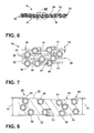
FIG. 6 is a cross-sectional view of the multilayer microsphere insulation system ofFIG. 5 taken along line VI-VI; -
FIG. 7 is an enlarged cross-sectional view of the multilayer microsphere insulation system ofFIG. 6 taken at area VII; -
FIG. 8 is a cross-sectional view of an aspect of a microsphere layer having a thickness greater than a diameter of one of the microspheres incorporated therein; and -
FIG. 9 is a schematic flow diagram illustrating a method for forming an insulative layer for an appliance utilizing an embodiment of the multilayer microsphere insulation system. - For purposes of description herein the terms "upper," "lower," "right," "left," "rear," "front," "vertical," "horizontal," and derivatives thereof shall relate to the device as oriented in
FIG. 1 . However, it is to be understood that the device may assume various alternative orientations and step sequences, except where expressly specified to the contrary. It is also to be understood that the specific devices and processes illustrated in the attached drawings, and described in the following specification are simply exemplary embodiments of the inventive concepts defined in the appended claims. Hence, specific dimensions and other physical characteristics relating to the embodiments disclosed herein are not to be considered as limiting, unless the claims expressly state otherwise. - As illustrated in
FIGS. 1-7 ,reference numeral 10 generally refers to a multilayer microsphere insulation system incorporated within aninsulating cavity 12 defined between anouter shell 14 and aninner shell 16 of an appliance, such as aheating appliance 18, according to at least one aspect. Theheating appliance 18 includes anouter shell 14 and aninner shell 16, where theouter shell 14 andinner shell 16 are engaged to define aninsulating cavity 12 therebetween. Theinner shell 16 includes aninner surface 20 that at least partially defines an interior cavity, such as aheating cavity 22 for theheating appliance 18. Amultilayer insulation member 24 includes a plurality oflayers 26, where each layer of the plurality oflayers 26 includes aninsulative sheet 28 defining first andsecond surfaces microspheres 34 that are at least partially disposed within theinsulative sheet 28. At least a portion of the plurality ofmicrospheres 34 extends outward from each of the first andsecond surfaces insulative sheet 28 to define a plurality ofmicrosphere protrusions 36 extending therefrom. It is contemplated that the engagement of twoadjacent layers 26 of the plurality oflayers 26 causes a portion of the plurality ofmicrosphere protrusions 36 ofadjacent layers 26 to engage and define a plurality ofinsulating air pockets 38 defined between theadjacent layers 26. The combination of thevarious layers 26 placed in a stacked or layered configuration forms a plurality of theinsulating air pockets 38 between each of theadjacent layers 26 and substantially forms the multilayermicrosphere insulation system 10. - Referring again to
FIGS. 1-7 , according to various embodiments, each of thelayers 26 having theinsulative sheet 28 and themicrospheres 34 disposed therein forms a plurality ofmicrosphere sheets 50 that can be disposed in a layered configuration to form the multilayermicrosphere insulation system 10. Each of themicrosphere sheets 50 includes a plurality ofmicrospheres 34 disposed in theinsulative sheet 28 that can be made of aflexible base material 52, wherein at least a portion of the plurality ofmicrospheres 34 extends outward from theflexible base material 52 to define first andsecond sets microsphere protrusions 36 on first andsecond surfaces flexible base material 52. When themicrosphere sheets 50 are placed in a layered configuration, thefirst set 54 ofmicrosphere protrusions 36 of afirst microsphere sheet 50 substantially engages thesecond set 56 ofmicrosphere protrusions 36 of anadjacent microsphere sheet 50 to define a plurality ofinsulating air pockets 38 defined between the first andadjacent microsphere sheets 50. - Referring again to
FIGS. 3-7 , within the multilayermicrosphere insulation system 10, it is contemplated that themicrospheres 34 can beglass microspheres 34 that are positioned in an irregular pattern within theinsulative sheet 28 of theflexible base material 52. By having a substantially irregular or irregular pattern ofmicrospheres 34 set within theinsulative sheet 28, when amicrosphere sheet 50 is placed in a layered configuration on anadjacent microsphere sheet 50, the irregular pattern ofmicrospheres 34 disposed within each of themicrosphere sheets 50 can cause an irregular engagement of themicrosphere protrusions 36 of each of themicrosphere sheets 50. This irregular engagement of themicrosphere protrusions 36 of eachmicrosphere sheet 50 can result in an irregular or substantially irregular pattern ofinsulating air pockets 38 defined between theadjacent microsphere sheets 50 of the multilayermicrosphere insulation system 10. It is contemplated that the irregular configuration of theinsulating air pockets 38 disposed between themicrosphere sheets 50 can result in the multilayermicrosphere insulation system 10 having a minimal number of, if any, portions of the multilayermicrosphere insulation system 10 having no, or being free of, aninsulating air pocket 38. In this manner, the irregular occurrences of the insulatingair pockets 38 can serve to limit the thermal transfer of heat through the multilayermicrosphere insulation system 10. - Referring again to
FIGS. 6 and 7 , it is contemplated that eachmicrosphere sheet 50 can have asheet thickness 70 that is substantially equal to amicrosphere thickness 72, or diameter where themicrosphere 34 is spherical in shape, of asingle microsphere 34. It is also contemplated that theinsulative sheet 28 of theflexible base material 52 can have amaterial thickness 74 that is less than themicrosphere thickness 72. In this manner, eachmicrosphere 34, being thicker than theinsulative sheet 28 offlexible base material 52, can define twoseparate microsphere protrusions 36 extending out of each of the opposing first andsecond surfaces microsphere sheet 50. Because themicrospheres 34 are irregularly disposed within themicrosphere sheet 50, themicrosphere protrusions 36 are also irregularly distributed throughout the opposing first andsecond surfaces microsphere sheet 50. In turn, because of the irregular distribution of themicrosphere protrusions 36,certain microsphere protrusions 36 may engage only theflexible base material 52 of anadjacent microsphere sheet 50. Whileother microsphere protrusions 36 may engage both theflexible base material 52 and amicrosphere protrusion 36 of anadjacent microsphere sheet 50, stillother microsphere protrusions 36 may engage only anothermicrosphere protrusion 36 of theadjacent microsphere sheet 50. Through this irregular configuration of themicrospheres 34 andmicrosphere protrusions 36, the engagement ofadjacent microsphere protrusions 36 results in the irregular placement and distribution of theinsulating air pockets 38, as well as irregular and varying thickness of the plurality ofinsulating air pockets 38 between eachmicrosphere sheet 50 and throughout the entire multilayermicrosphere insulation system 10. - According to various embodiments, it is contemplated that the placement of
microspheres 34 within one ormore microsphere sheets 50 of the multilayermicrosphere insulation system 10 can be in a regular pattern or substantially regular pattern. It is also contemplated that within the multilayermicrosphere insulation system 10,certain microsphere sheets 50 can have regularly spacedmicrospheres 34 andother microsphere sheets 50 can have irregularly spacedmicrospheres 34. It is also contemplated that the spacing of themicrospheres 34. It is also contemplated that the spacing of themicrospheres 34 within asingle microsphere sheet 50 can be regular in some areas and irregular in others. The exact configuration of themicrosphere 34 spacing can be determined based upon the design of the appliance and the desired configuration of theinsulating air pockets 38 to be formed between themicrosphere sheets 50. - According to the various embodiments, the engagement between
microspheres 34 ofadjacent microsphere sheets 50 may only be at very small connection points, such as, for example, the very small engagement points between touching spheres. This very small engagement betweenmicrospheres 34 along with theinsulating air pockets 38 formed by themicrosphere sheets 50 can create a lengthy path for heat conduction. Accordingly, themicrosphere sheets 50 and theinsulating air pockets 38 formed irregularly therebetween forms a multilayermicrosphere insulation system 10 having a highly effective insulating quality. - Referring again to
FIGS. 2-7 , it is contemplated that theinsulative sheet 28 of theflexible base material 52 can be a silicone sheet made of pure silicone or of a silicone-based material, having the substantially the same, or the same, thermal properties as silicone. It is also contemplated that materials other than silicone can be used as theinsulative sheet 28 offlexible base material 52, so long as such a material has a reflective thermal characteristic, similar to that of silicone, and can be placed in sheets to form the multilayermicrosphere insulation system 10. - Referring again to
FIGS. 2-7 , where silicone is used as theflexible base material 52, thevarious microsphere sheets 50 can be held together in the layered configuration through surface adhesion, such that themicrosphere sheets 50 are free of, or substantially free of, the use of adhesives. The surface adhesion of thevarious microsphere sheets 50 also can result in a multilayermicrosphere insulation system 10 that is substantially free of fasteners, brackets, holders, or other similar mechanisms that might serve to hold themicrosphere layers 26 of the multilayermicrosphere insulation system 10 together beyond the adhesive forces resulting from the material characteristics of the particularflexible base material 52 incorporated within themicrosphere sheet 50. - Referring again to
FIGS. 2-7 , it is contemplated that each of themicrosphere sheets 50 can be formed by extruding a mixture of theflexible base material 52 and themicrospheres 34 into eachmicrosphere sheet 50. According to the various embodiments, it is contemplated that each of the plurality oflayers 26 of the multilayermicrosphere insulation system 10 can be an extruded layer of silicone andglass microspheres 34 that, when extruded, forms thevarious microsphere sheets 50 for the multilayermicrosphere insulation system 10. According to various alternate embodiments, it is contemplated that eachmicrosphere sheet 50 of the multilayermicrosphere insulation system 10 is a spray-on layer that can be sprayed on a substrate, wherein the sprayed layer can be dried, cured, or otherwise set to form anindividual microsphere sheet 50. Eachsubsequent microsphere sheet 50 of the multilayermicrosphere insulation system 10 can be subsequently sprayed on to either the same substrate or onto the previously sprayed and curedmicrosphere sheet 50 to form each subsequent layer of the multilayermicrosphere insulation system 10. In this manner, the spray-oninsulation layers 26 can be sprayed directly onto theouter shell 14 orinner shell 16 of theheating appliance 18, according to various embodiments. It is also contemplated that the multilayermicrosphere insulation system 10 can be formed through a combination ofextruded microsphere sheets 50 and sprayed onmicrosphere sheets 50 to form the multilayermicrosphere insulation system 10 for theheating appliance 18. - Referring again to
FIGS. 6 and 7 , it is contemplated that at least a portion of themicrospheres 34 of the multilayermicrosphere insulation system 10 can behollow glass microspheres 34 having anouter wall 90 that defines aninterior microsphere cavity 92. It is also contemplated that an insulating gas can be disposed within theinterior microsphere cavity 92. Such an insulating gas can be an inert gas, such as argon, xenon, air, or other similar insulating gas. - According to the various embodiments, it is contemplated that the
microspheres 34 for the multilayermicrosphere insulation system 10 can be made of various materials that can include, but are not limited to, glass, ceramic, combinations thereof, and other similar thermally resistant materials. It is also contemplated that themicrospheres 34 can be solid, hollow, or hollow and filled with a separate insulative material. According to the various embodiments, it is contemplated that different configurations of thesemicrospheres 34 can be incorporated within thevarious microsphere sheets 50 of the multilayermicrosphere insulation system 10. The various microsphere configurations can also be incorporated within eachmicrosphere sheet 50 of the multilayermicrosphere insulation system 10. - According to the various embodiments, the
microspheres 34 can be any one of various shapes that can include, but are not limited to, spherical, oblong, irregular-shaped, polygonal, prism-shaped, combinations thereof, and other similar configurations. It is contemplated that the size of each of themicrospheres 34 can vary and can have amicrosphere thickness 72 within the range of nanometers to microns to fractions of a millimeter, as well as varying ranges included therebetween. Additionally, within eachmicrosphere sheet 50, the density ofmicrospheres 34 disposed within eachmicrosphere sheet 50 can vary. Typically, a larger number ofmicrospheres 34 within eachmicrosphere sheet 50 may result in a greater number of insulatingair pockets 38 disposed between each of themicrosphere sheets 50. Conversely, lesser numbers ofmicrospheres 34 within eachmicrosphere sheet 50 will result in fewer insulative air pockets disposed between themicrosphere sheets 50 within the multilayermicrosphere insulation system 10. The exact density ofmicrospheres 34, the size ofmicrospheres 34 used, the material and configuration of themicrospheres 34 can depend upon the desired configuration of each of themicrosphere sheets 50 and the entire configuration of the multilayermicrosphere insulation system 10. - In forming the multilayer
microsphere insulation system 10, themicrospheres 34 include a certain insulating property, depending on the design of themicrospheres 34 used for eachmicrosphere sheet 50. Theinsulative sheets 28 offlexible base material 52, such as silicone, also includes a thermally reflective property that can add to the insulating properties of themicrospheres 34. When themicrosphere sheets 50 are layered to form the multilayermicrosphere insulation system 10, the formation of the insulatingair pockets 38 provides additional insulating properties that can serve to increase the overall insulative characteristics of the combination of themicrosphere sheets 50. In this manner, the overall system of themicrosphere sheets 50 and the insulatingair pockets 38 formed therebetween creates amultilayer insulation member 24 having increased insulation properties and having a thinner overall thickness. This thinnermultilayer insulation member 24 can allow appliances, such as ovens (as exemplified inFIGS. 1 and2 ), to be made with thinner insulating cavities. Therefore, more space can be devoted to creating a larger interior volume, such as aheating cavity 22, a refrigerating or freezing cavity or other appliance internal volume. Accordingly, while an oven is exemplified inFIGS. 1 and2 , the multilayermicrosphere insulation system 10 can be implemented in any one or more of various appliances. Such appliances can include, but are not limited to, ovens, ranges, refrigerators, freezers, microwaves, toasters, toaster ovens, dishwashers, clothes washing/drying machines, small appliances and others to provide for thermal insulation, sound insulation or both. The multilayermicrosphere insulation system 10 can also be used in various household fixtures including, but not limited to, insulation panels, cabinetry, wall/roof/floor insulation, light fixtures, sound dampening fixtures, as well as others. - Referring now to
FIG. 8 , according to various embodiments, it is contemplated that theinsulative sheet 28 of theflexible base material 52 can be made to have amaterial thickness 74 greater than themicrosphere thickness 72 of thevarious microspheres 34 included within theparticular microsphere sheet 50. In such an embodiment, it is contemplated that thevarious microspheres 34 can be positioned in various vertical ranges within theflexible base material 52. Accordingly, eachmicrosphere 34 may form no more than onemicrosphere protrusion 36 extending out from either the first orsecond surface microsphere sheet 50. It is also contemplated thatvarious microspheres 34 would be entirely encased within theflexible base material 52 of theinsulative sheet 28 where such amicrosphere 34 would not form any of themicrosphere protrusions 36 of themicrosphere sheet 50. According to the various embodiments, it is contemplated that the multilayermicrosphere insulation system 10 can be made up ofvarious microsphere sheets 50 having thicker orthinner layers 26 of theflexible base material 52 within which themicrospheres 34 are disposed. It is also contemplated that theinsulative sheets 28 offlexible base material 52 can have avariable material thickness 74 that can be thinner than amicrosphere thickness 72 in one or more areas, can be the same thickness as themicrospheres 34 in one or more other areas, and thicker than themicrosphere thickness 72 in one or more other areas. Again, the exact configuration of the microsphere layers 26 can vary depending on the appliance design and the insulating levels needed therein. - Referring again to
FIGS. 2-7 , in the various embodiments where theflexible base material 52 has amaterial thickness 74 that is less than themicrosphere thickness 72, it is contemplated that thevarious microspheres 34 can be set within theflexible base material 52 at various vertical positions relative to theflexible base material 52. Accordingly, some of themicrospheres 34 may be set higher or lower within theflexible base material 52 such that only one side of themicrosphere 34 extends from theflexible base material 52 to form asingle microsphere protrusion 36. Alternatively, such an offset configuration of eachmicrosphere 34 may form alarger microsphere protrusion 36 on one surface of theflexible base material 52 and asmaller microsphere protrusion 36 on the opposing surface of theflexible base material 52. This irregular vertical positioning of each of themicrospheres 34 can further provide the irregularity discussed above as to the positioning of the various insulative air pockets between each of themicrosphere sheets 50 and throughout the entire multilayermicrosphere insulation system 10. Accordingly, a morepronounced microsphere protrusion 36 caused by an offsetmicrosphere 34 within theinsulative sheet 28 may result in a larger insulative air pocket proximate the morepronounced microsphere protrusion 36. Conversely, a lesspronounced microsphere protrusion 36 may result in a smaller insulative air pocket. Alternatively, where themicrosphere protrusion 36, regardless of its size, engages a portion of theflexible base material 52 only, it is contemplated that theflexible base material 52 may conform to the shape of themicrosphere protrusion 36 such that no insulative air pocket may be formed in that particular location. As discussed above, the irregular configuration of themicrospheres 34 set within theinsulative sheet 28 of theflexible base material 52 serves to limit the occurrence of substantial portions betweenadjacent microsphere sheets 50 that are free of insulating air pockets 38. - Referring now to
FIGS. 1-7 and9 , having described the multilayermicrosphere insulation system 10, amethod 400 is disclosed for forming the multilayermicrosphere insulation system 10 to be disposed within theheating cavity 22 of aheating appliance 18, according to at least one aspect. According to themethod 400, astep 402 includes disposing a plurality ofmicrospheres 34 within aflexible base material 52. As discussed above, theflexible base material 52 can be silicone, a silicone-based material, or other similar thermally resistive material. The amount ofmicrospheres 34 disposed within theflexible base material 52 can vary depending upon the desired density ofmicrospheres 34 within eachmicrosphere sheet 50 of the multilayermicrosphere insulation system 10. According to themethod 400,step 404 includes forming theflexible base material 52 with the plurality ofmicrospheres 34 disposed therein into a plurality ofmicrosphere sheets 50. As discussed above, each of the plurality ofmicrosphere sheets 50 includes a plurality ofmicrosphere protrusions 36 that extends outward from the surface of eachmicrosphere sheet 50. - According to the various embodiments, each of the
microsphere protrusions 36 is defined by one of themicrospheres 34 disposed within themicrosphere sheet 50. Depending upon the placement of themicrospheres 34 within theinsulative sheet 28 of theflexible base material 52, eachmicrosphere 34 can define either onemicrosphere protrusion 36 extending from one surface of themicrosphere sheet 50, or, opposingmicrosphere protrusions 36 extending out of opposing surfaces of amicrosphere sheet 50. As discussed previously,material thickness 74 of theflexible base material 52 can be thicker than themicrosphere thickness 72 of eachmicrosphere 34 such that eachmicrosphere 34 may form only onemicrosphere protrusion 36, and in some instances, may be entirely surrounded by theflexible base material 52 such that aparticular microsphere 34 may not define anymicrosphere protrusions 36 of themicrosphere sheet 50. - Referring again to
FIG. 9 , once themicrosphere sheets 50 are formed, the plurality ofmicrosphere sheets 50 can be disposed in a layered configuration to form the multilayer microsphere insulation system 10 (step 406). In this manner, a portion of the plurality ofmicrosphere protrusions 36 of afirst microsphere sheet 50 can substantially engage, or engage, a portion of the plurality ofmicrosphere protrusions 36 of a secondadjacent microsphere sheet 50. Accordingly, a plurality of insulatingair pockets 38 are formed between theadjacent microsphere sheets 50. - Referring again to
FIG. 9 , once the multilayermicrosphere insulation system 10 is formed, themultilayer insulation member 24 of the multilayermicrosphere insulation system 10 that is defined by thelayered microsphere sheets 50 can be placed on at least one of theouter shell 14 and theinner shell 16 of the heating appliance 18 (step 408). It is also contemplated that themultilayer insulation member 24 can be placed between theouter shell 14 andinner shell 16 such that theouter shell 14 andinner shell 16 can be attached together to form an insulatingcavity 12 with themultilayer insulation member 24 disposed within the insulatingcavity 12 defined between theouter shell 14 and the inner shell 16 (step 410). - According to the various embodiments, step 404 of forming the
flexible base material 52 with the plurality ofmicrospheres 34 disposed therein into themicrosphere sheets 50 can be accomplished by extruding theflexible base material 52 and the plurality ofmicrospheres 34 into the plurality ofmicrosphere sheets 50. It is contemplated that a single sheet of themicrospheres 34 andflexible base material 52 can be extruded and the elongated sheet can be cut to form themicrosphere sheets 50 used for the multilayermicrosphere insulation system 10. Other methods of forming themicrosphere sheets 50 can be used, where such methods can include, but are not limited to, spraying theflexible base material 52 andmicrospheres 34, rolling theflexible base material 52 andmicrospheres 34, such as with a paint roller, or a brush, pouring theflexible base material 52 andmicrospheres 34 into a form for curing, stamping, molding, and other similar methods for forming thevarious microsphere sheets 50 for the multilayermicrosphere insulation system 10. - According to the various embodiments, or exemplified in
FIGS. 1-9 , it is contemplated that the multilayermicrosphere insulation system 10 can be disposed throughout thevarious sidewalls 94 of theheating appliance 18, including aback wall 96. Additionally, the multilayermicrosphere insulation system 10 can be disposed within adoor 98 of theheating appliance 18. The multilayermicrosphere insulation system 10 can also be provided within mullions, dividing walls, partitions and other interior and exterior wall members of various household appliances. - The various embodiments of the multilayer
microsphere insulation system 10 disclosed herein, when implemented within household appliances, such as within an insulatingcavity 12 of aheating appliance 18, provide for improved insulating performance. Additionally, this improved insulating performance can be accomplished with a thinner insulatingcavity 12. This thinner insulatingcavity 12, in turn, provides room for additional cooking space within theheating cavity 22 of theheating appliance 18. The various methods of formation and installation of the multilayermicrosphere insulation system 10, as disclosed herein, provide for a method of manufacture that can minimize waste of material due to the use of themicrosphere sheets 50 over conventional batting-type insulation. These novel improvements, in turn, conserve money and resources. The method of forming themicrosphere sheets 50, the multilayermicrosphere insulation system 10 and theheating appliance 18, as a whole, can also decrease the time necessary to manufacture theheating appliance 18. This decrease in time is, at least in part, due to the components incorporated into the multilayermicrosphere insulation system 10 and the ability to efficiently form and install these components into the multilayermicrosphere insulation system 10 and theheating appliance 18.
Claims (15)
- A multilayer insulation member (24) for an appliance, the insulation member (24) comprising:a plurality of microsphere sheets (50) disposed in a layered configuration, wherein each microsphere sheet (50) includes a plurality of microspheres (34) disposed in an insulative sheet (28), wherein at least a portion of the plurality of microspheres (34) extends outward from the insulative sheet (28) to define first and second sets of microsphere protrusions (36) on first and second sides of the insulative sheet (28), wherein the first set of microsphere protrusions (36) of a first microsphere sheet (50) of the plurality of microsphere sheets (50) engages the second set of microsphere protrusions (36) of an adjacent microsphere sheet (50) of the plurality of microsphere sheets (50) to define a plurality of insulating air pockets (38) defined between the first and adjacent microsphere sheets (50).
- The multilayer insulation member (24) of claim 1, wherein the insulative sheet (28) includes a flexible base material (52).
- The multilayer insulation member (24) of any one or more of claims 1 and 2, wherein each of the plurality of microspheres (34) are glass microspheres (34).
- The multilayer insulation member (24) of any one or more of claims 1-3, wherein at least a portion of the plurality of microspheres (34) are hollow glass microspheres (34) having an outer wall (90) that defines an interior microsphere cavity (92).
- The multilayer insulation member (24) of any one or more of claims 1-4, wherein the plurality of microsphere sheets (50) disposed in a layered configuration are disposed within an insulating cavity (12) of an appliance, wherein the insulating cavity (12) is defined between an outer shell (14) and an inner shell (16), and wherein the inner shell (16) includes an inner surface (20) that defines an interior cavity.
- The multilayer insulation member (24) of any one or more of claims 1-5, wherein each of the plurality of microspheres (34) includes a microsphere thickness (72) and the insulative sheet (28) has a material thickness (74), wherein the material thickness (74) is less than the microsphere thickness (72), and wherein each microsphere (34) defines first and second sets of microsphere protrusions (36) that extend from the first and second surfaces (30, 32), respectively.
- The multilayer insulation member (24) of any one or more of claims 1-6, wherein the insulative sheet (28) is a silicone sheet.
- The multilayer insulation member (24) of any one or more of claims 1-7, wherein the plurality of microspheres (34) are positioned in an irregular pattern within the insulative sheet (28).
- The multilayer insulation member (24) of any one or more of claims 1-8, wherein each of the plurality of microsphere sheets (50) is one of an extruded layer of silicone and microspheres (34) and a spray-on layer of silicone and microspheres (34).
- The multilayer insulation member (24) of any one or more of claims 3-9, wherein an insulating gas is disposed within the interior microsphere cavity (92).
- The multilayer insulation member (24) of any one or more of claims 1-10, wherein each of the microsphere sheets (50) are held in a layered configuration through surface adhesion and the microsphere sheets (50) are free of the use of adhesives.
- The multilayer insulation member (24) of any one or more of claims 1-4 and 6-11, wherein each of the plurality of microspheres (34) includes a microsphere thickness (72) and the insulative layer has a material thickness (74), wherein the material thickness (74) is greater than the microsphere thickness (72), and wherein at least a portion of the plurality of microspheres (34) define one of first and second sets of microsphere protrusions (36) that extend from the first and second surfaces (30, 32), respectively.
- The multilayer insulation member (24) of any one or more of claims 2-12, wherein the appliance is a heating appliance (18) and the interior cavity is a heating cavity (22).
- The multilayer insulation member (24) insulation member of claim 9, wherein the plurality of microsphere sheets (50) include at least one of a regular pattern of on microspheres (34) and an irregular pattern of microspheres (34).
- A method for forming an insulation member (24) for an appliance according to the apparatus of any one or more of claims 1-14, the method comprising steps of:disposing a plurality of microspheres (34) within a flexible base material (52);forming the flexible base material (52) with the plurality of microspheres (34) disposed therein into plurality of microsphere sheets (50), wherein each of the plurality of microsphere sheets (50) includes a plurality of microsphere protrusions (36) that extend outward from a surface of each microsphere sheet (50), and wherein each of the protrusions (36) is defined by a microsphere (34) of the plurality of microspheres (34);layering the plurality of microsphere sheets (50), wherein a portion of the plurality of protrusions (36) of a first microsphere sheet (50) substantially engages a portion of the plurality of protrusions (36) of a second microsphere sheet (50) such that a plurality of insulating air pockets are formed between the first and second microsphere sheets (50), and wherein a layered plurality of microsphere sheets (50) forms an insulation member (24) for an appliance;placing the insulation member (24) formed from the layered plurality of microsphere sheets (50) on at least one of an outer shell (14) and an inner shell (16) of the appliance; andattaching the outer shell (14) and the inner shell (16) together to form an insulating cavity (12) with the insulation member (24) disposed within the insulating cavity (12).
Applications Claiming Priority (1)
| Application Number | Priority Date | Filing Date | Title |
|---|---|---|---|
| US14/709,896 US9630381B2 (en) | 2015-05-12 | 2015-05-12 | Insulation system for a cooking appliance incorporating a plurality of microsphere sheets |
Publications (2)
| Publication Number | Publication Date |
|---|---|
| EP3093562A1 true EP3093562A1 (en) | 2016-11-16 |
| EP3093562B1 EP3093562B1 (en) | 2018-12-19 |
Family
ID=56083876
Family Applications (1)
| Application Number | Title | Priority Date | Filing Date |
|---|---|---|---|
| EP16162102.4A Not-in-force EP3093562B1 (en) | 2015-05-12 | 2016-03-23 | Insulation system for a cooking appliance incorporating a plurality of microsphere sheets |
Country Status (2)
| Country | Link |
|---|---|
| US (3) | US9630381B2 (en) |
| EP (1) | EP3093562B1 (en) |
Families Citing this family (5)
| Publication number | Priority date | Publication date | Assignee | Title |
|---|---|---|---|---|
| GB2517973B (en) * | 2013-09-06 | 2016-11-02 | D & A Concept Design Ltd | An energy saving electric kettle |
| US9630381B2 (en) | 2015-05-12 | 2017-04-25 | Whirlpool Corporation | Insulation system for a cooking appliance incorporating a plurality of microsphere sheets |
| US11431100B2 (en) | 2016-03-25 | 2022-08-30 | Commscope Technologies Llc | Antennas having lenses formed of lightweight dielectric materials and related dielectric materials |
| CN113140915A (en) * | 2016-03-25 | 2021-07-20 | 康普技术有限责任公司 | Antenna with lens formed of lightweight dielectric material and associated dielectric material |
| WO2019055134A1 (en) | 2017-09-15 | 2019-03-21 | Commscope Technologies Llc | Methods of preparing a composite dielectric material |
Citations (7)
| Publication number | Priority date | Publication date | Assignee | Title |
|---|---|---|---|---|
| FR2115665A5 (en) * | 1970-11-27 | 1972-07-07 | Commissariat Energie Atomique | |
| EP0012038A1 (en) * | 1978-12-04 | 1980-06-11 | Air Products And Chemicals, Inc. | Superinsulation system |
| EP0110143A1 (en) * | 1982-10-29 | 1984-06-13 | COMPAGNIE EUROPEENNE POUR L'EQUIPEMENT MENAGER "CEPEM" Société anonyme dite: | Apparatus with cooking enclosure |
| US4548196A (en) * | 1978-08-28 | 1985-10-22 | Torobin Leonard B | Solar collector comprising transparent hollow plastic microspheres as insulation material |
| US5175975A (en) * | 1988-04-15 | 1993-01-05 | Midwest Research Institute | Compact vacuum insulation |
| GB2431974A (en) * | 2005-11-01 | 2007-05-09 | Corus Uk Ltd | Insulation coating for pipework |
| JP2008240507A (en) * | 2007-02-27 | 2008-10-09 | Mitsubishi Electric Corp | Insulation, insulation sheet and heat insulation sheet |
Family Cites Families (19)
| Publication number | Priority date | Publication date | Assignee | Title |
|---|---|---|---|---|
| US3607169A (en) | 1968-11-07 | 1971-09-21 | Exxon Research Engineering Co | Method for producing evacuated glass microspheres |
| US3614388A (en) | 1970-06-22 | 1971-10-19 | Aubrey C Robinson | Electric heating oven system |
| DE2965616D1 (en) | 1978-08-17 | 1983-07-14 | Ici Plc | Compositions of vermiculite lamellae and solid particulate materials and process for the production of vermiculite articles |
| FR2575407B1 (en) * | 1984-12-31 | 1987-03-20 | Hutchinson | NOVEL THERMAL INSULATING MATERIAL, OF THE SYNTACTIC TYPE, BASED ON ELASTOMERS IN PARTICULARLY, PARTIALLY OR TOTALLY FLAMMABLE |
| US5157893A (en) * | 1988-04-15 | 1992-10-27 | Midwest Research Institute | Compact vacuum insulation |
| DE69629053T2 (en) | 1995-01-13 | 2004-04-22 | Minnesota Mining And Mfg. Co., St. Paul | Method and composition for connecting components to glass |
| US5612066A (en) * | 1995-04-11 | 1997-03-18 | Davidson Textron, Inc. | Heat insulating mold panel for a mold tool |
| DE19745825A1 (en) | 1997-10-16 | 1999-04-22 | Bosch Siemens Hausgeraete | Thermally insulated cavity-walled case for e.g. Refrigerator |
| US7037865B1 (en) | 2000-08-08 | 2006-05-02 | Moldite, Inc. | Composite materials |
| WO2003072684A1 (en) | 2002-02-26 | 2003-09-04 | Technology Applications, Inc. | Microsphere insulation systems |
| US8132382B2 (en) | 2004-06-17 | 2012-03-13 | Certainteed Corporation | Insulation containing heat expandable spherical additives, calcium acetate, cupric carbonate, or a combination thereof |
| US7794805B2 (en) | 2007-06-29 | 2010-09-14 | Schlumberger Technology Corporation | Thermal insulation barriers |
| US9359529B2 (en) | 2008-10-29 | 2016-06-07 | 3M Innovative Properties Company | Electron beam cured silicone materials |
| RS52356B (en) | 2009-07-31 | 2012-12-31 | Druckfarben Hellas S.A. | SYSTEM FOR THERMAL INSULATION OF BUILDINGS AND FOR LIQUID STORAGE AND TRANSPORT SYSTEMS |
| WO2011139573A2 (en) | 2010-04-28 | 2011-11-10 | 3M Innovative Properties Company | Silicone-based material |
| DE102010017087B4 (en) | 2010-05-26 | 2013-08-22 | Schott Ag | fireplace |
| ES2693673T3 (en) | 2011-07-07 | 2018-12-13 | 3M Innovative Properties Company | Article that includes multicomponent fibers and hollow ceramic microspheres and methods of manufacturing and use thereof |
| WO2013129488A1 (en) | 2012-02-28 | 2013-09-06 | 株式会社カネカ | Coating composition and coating film obtained from coating composition |
| US9630381B2 (en) * | 2015-05-12 | 2017-04-25 | Whirlpool Corporation | Insulation system for a cooking appliance incorporating a plurality of microsphere sheets |
-
2015
- 2015-05-12 US US14/709,896 patent/US9630381B2/en active Active
-
2016
- 2016-03-23 EP EP16162102.4A patent/EP3093562B1/en not_active Not-in-force
-
2017
- 2017-04-11 US US15/484,367 patent/US10386077B2/en active Active
-
2019
- 2019-07-05 US US16/503,836 patent/US11035577B2/en active Active
Patent Citations (7)
| Publication number | Priority date | Publication date | Assignee | Title |
|---|---|---|---|---|
| FR2115665A5 (en) * | 1970-11-27 | 1972-07-07 | Commissariat Energie Atomique | |
| US4548196A (en) * | 1978-08-28 | 1985-10-22 | Torobin Leonard B | Solar collector comprising transparent hollow plastic microspheres as insulation material |
| EP0012038A1 (en) * | 1978-12-04 | 1980-06-11 | Air Products And Chemicals, Inc. | Superinsulation system |
| EP0110143A1 (en) * | 1982-10-29 | 1984-06-13 | COMPAGNIE EUROPEENNE POUR L'EQUIPEMENT MENAGER "CEPEM" Société anonyme dite: | Apparatus with cooking enclosure |
| US5175975A (en) * | 1988-04-15 | 1993-01-05 | Midwest Research Institute | Compact vacuum insulation |
| GB2431974A (en) * | 2005-11-01 | 2007-05-09 | Corus Uk Ltd | Insulation coating for pipework |
| JP2008240507A (en) * | 2007-02-27 | 2008-10-09 | Mitsubishi Electric Corp | Insulation, insulation sheet and heat insulation sheet |
Also Published As
| Publication number | Publication date |
|---|---|
| EP3093562B1 (en) | 2018-12-19 |
| US20190331345A1 (en) | 2019-10-31 |
| US20160332427A1 (en) | 2016-11-17 |
| US9630381B2 (en) | 2017-04-25 |
| US11035577B2 (en) | 2021-06-15 |
| US10386077B2 (en) | 2019-08-20 |
| US20170219217A1 (en) | 2017-08-03 |
Similar Documents
| Publication | Publication Date | Title |
|---|---|---|
| US11035577B2 (en) | Insulation system for a cooking appliance incorporating a plurality of microsphere sheets | |
| US10203120B2 (en) | Insulation for baking ovens | |
| CN101796358A (en) | Refrigeration unit with vacuum insulation | |
| EP2554759A2 (en) | High-performance vacuum insulation panel and manufacturing method thereof | |
| US20130149477A1 (en) | High performance insulated panel | |
| JP2017180875A (en) | refrigerator | |
| EP1898159A3 (en) | Improved insulation for baking chambers in a multi-deck baking oven | |
| ITVA20010040A1 (en) | DOMESTIC REFRIGERATOR WITH IMPROVED THERMAL INSULATION | |
| KR20140102808A (en) | Door for a refrigerator and method for manufacturing the same, | |
| CN205536799U (en) | Baffle assembly and refrigerator for refrigerator | |
| CN111853429A (en) | Barrier layer for thermal insulation structures | |
| KR102315543B1 (en) | Heat dissipation sheet | |
| CN203501255U (en) | Baking tray component for microwave oven | |
| CN203501256U (en) | Baking tray component for microwave oven | |
| US20140021199A1 (en) | Handle with a heat sink | |
| CN204931388U (en) | Cooking apparatus | |
| WO2013082890A1 (en) | Thermally-insulated electric oven | |
| CN106264185B (en) | Wind-guiding heat dissipation formula electric oven | |
| CN111721059A (en) | A kind of sticking method of vacuum insulation board and refrigerator | |
| CN203501258U (en) | Baking tray component for microwave oven | |
| CN204730269U (en) | For panel and the electromagnetic oven of electromagnetic oven | |
| CN222667413U (en) | Thermal-insulated pvc wallboard keeps warm | |
| CN202432800U (en) | Refrigerator inner container | |
| CN110151006B (en) | Toaster heat insulation and dissipation structure and toaster | |
| CN103471323B (en) | For the central sill of refrigeration plant and the refrigeration plant with it |
Legal Events
| Date | Code | Title | Description |
|---|---|---|---|
| PUAI | Public reference made under article 153(3) epc to a published international application that has entered the european phase |
Free format text: ORIGINAL CODE: 0009012 |
|
| AK | Designated contracting states |
Kind code of ref document: A1 Designated state(s): AL AT BE BG CH CY CZ DE DK EE ES FI FR GB GR HR HU IE IS IT LI LT LU LV MC MK MT NL NO PL PT RO RS SE SI SK SM TR |
|
| AX | Request for extension of the european patent |
Extension state: BA ME |
|
| STAA | Information on the status of an ep patent application or granted ep patent |
Free format text: STATUS: REQUEST FOR EXAMINATION WAS MADE |
|
| 17P | Request for examination filed |
Effective date: 20170516 |
|
| RBV | Designated contracting states (corrected) |
Designated state(s): AL AT BE BG CH CY CZ DE DK EE ES FI FR GB GR HR HU IE IS IT LI LT LU LV MC MK MT NL NO PL PT RO RS SE SI SK SM TR |
|
| GRAP | Despatch of communication of intention to grant a patent |
Free format text: ORIGINAL CODE: EPIDOSNIGR1 |
|
| STAA | Information on the status of an ep patent application or granted ep patent |
Free format text: STATUS: GRANT OF PATENT IS INTENDED |
|
| RIC1 | Information provided on ipc code assigned before grant |
Ipc: B32B 25/20 20060101ALI20180904BHEP Ipc: E04B 1/76 20060101ALI20180904BHEP Ipc: F24C 15/34 20060101AFI20180904BHEP Ipc: A47L 15/42 20060101ALI20180904BHEP |
|
| INTG | Intention to grant announced |
Effective date: 20180920 |
|
| GRAS | Grant fee paid |
Free format text: ORIGINAL CODE: EPIDOSNIGR3 |
|
| GRAA | (expected) grant |
Free format text: ORIGINAL CODE: 0009210 |
|
| STAA | Information on the status of an ep patent application or granted ep patent |
Free format text: STATUS: THE PATENT HAS BEEN GRANTED |
|
| AK | Designated contracting states |
Kind code of ref document: B1 Designated state(s): AL AT BE BG CH CY CZ DE DK EE ES FI FR GB GR HR HU IE IS IT LI LT LU LV MC MK MT NL NO PL PT RO RS SE SI SK SM TR |
|
| REG | Reference to a national code |
Ref country code: GB Ref legal event code: FG4D |
|
| REG | Reference to a national code |
Ref country code: CH Ref legal event code: EP |
|
| REG | Reference to a national code |
Ref country code: IE Ref legal event code: FG4D |
|
| REG | Reference to a national code |
Ref country code: DE Ref legal event code: R096 Ref document number: 602016008322 Country of ref document: DE |
|
| REG | Reference to a national code |
Ref country code: AT Ref legal event code: REF Ref document number: 1079151 Country of ref document: AT Kind code of ref document: T Effective date: 20190115 |
|
| REG | Reference to a national code |
Ref country code: NL Ref legal event code: MP Effective date: 20181219 |
|
| PG25 | Lapsed in a contracting state [announced via postgrant information from national office to epo] |
Ref country code: LT Free format text: LAPSE BECAUSE OF FAILURE TO SUBMIT A TRANSLATION OF THE DESCRIPTION OR TO PAY THE FEE WITHIN THE PRESCRIBED TIME-LIMIT Effective date: 20181219 Ref country code: NO Free format text: LAPSE BECAUSE OF FAILURE TO SUBMIT A TRANSLATION OF THE DESCRIPTION OR TO PAY THE FEE WITHIN THE PRESCRIBED TIME-LIMIT Effective date: 20190319 Ref country code: FI Free format text: LAPSE BECAUSE OF FAILURE TO SUBMIT A TRANSLATION OF THE DESCRIPTION OR TO PAY THE FEE WITHIN THE PRESCRIBED TIME-LIMIT Effective date: 20181219 Ref country code: BG Free format text: LAPSE BECAUSE OF FAILURE TO SUBMIT A TRANSLATION OF THE DESCRIPTION OR TO PAY THE FEE WITHIN THE PRESCRIBED TIME-LIMIT Effective date: 20190319 Ref country code: HR Free format text: LAPSE BECAUSE OF FAILURE TO SUBMIT A TRANSLATION OF THE DESCRIPTION OR TO PAY THE FEE WITHIN THE PRESCRIBED TIME-LIMIT Effective date: 20181219 Ref country code: LV Free format text: LAPSE BECAUSE OF FAILURE TO SUBMIT A TRANSLATION OF THE DESCRIPTION OR TO PAY THE FEE WITHIN THE PRESCRIBED TIME-LIMIT Effective date: 20181219 |
|
| REG | Reference to a national code |
Ref country code: LT Ref legal event code: MG4D |
|
| REG | Reference to a national code |
Ref country code: AT Ref legal event code: MK05 Ref document number: 1079151 Country of ref document: AT Kind code of ref document: T Effective date: 20181219 |
|
| PG25 | Lapsed in a contracting state [announced via postgrant information from national office to epo] |
Ref country code: RS Free format text: LAPSE BECAUSE OF FAILURE TO SUBMIT A TRANSLATION OF THE DESCRIPTION OR TO PAY THE FEE WITHIN THE PRESCRIBED TIME-LIMIT Effective date: 20181219 Ref country code: AL Free format text: LAPSE BECAUSE OF FAILURE TO SUBMIT A TRANSLATION OF THE DESCRIPTION OR TO PAY THE FEE WITHIN THE PRESCRIBED TIME-LIMIT Effective date: 20181219 Ref country code: SE Free format text: LAPSE BECAUSE OF FAILURE TO SUBMIT A TRANSLATION OF THE DESCRIPTION OR TO PAY THE FEE WITHIN THE PRESCRIBED TIME-LIMIT Effective date: 20181219 Ref country code: GR Free format text: LAPSE BECAUSE OF FAILURE TO SUBMIT A TRANSLATION OF THE DESCRIPTION OR TO PAY THE FEE WITHIN THE PRESCRIBED TIME-LIMIT Effective date: 20190320 |
|
| PG25 | Lapsed in a contracting state [announced via postgrant information from national office to epo] |
Ref country code: NL Free format text: LAPSE BECAUSE OF FAILURE TO SUBMIT A TRANSLATION OF THE DESCRIPTION OR TO PAY THE FEE WITHIN THE PRESCRIBED TIME-LIMIT Effective date: 20181219 |
|
| PG25 | Lapsed in a contracting state [announced via postgrant information from national office to epo] |
Ref country code: ES Free format text: LAPSE BECAUSE OF FAILURE TO SUBMIT A TRANSLATION OF THE DESCRIPTION OR TO PAY THE FEE WITHIN THE PRESCRIBED TIME-LIMIT Effective date: 20181219 Ref country code: PL Free format text: LAPSE BECAUSE OF FAILURE TO SUBMIT A TRANSLATION OF THE DESCRIPTION OR TO PAY THE FEE WITHIN THE PRESCRIBED TIME-LIMIT Effective date: 20181219 Ref country code: CZ Free format text: LAPSE BECAUSE OF FAILURE TO SUBMIT A TRANSLATION OF THE DESCRIPTION OR TO PAY THE FEE WITHIN THE PRESCRIBED TIME-LIMIT Effective date: 20181219 Ref country code: PT Free format text: LAPSE BECAUSE OF FAILURE TO SUBMIT A TRANSLATION OF THE DESCRIPTION OR TO PAY THE FEE WITHIN THE PRESCRIBED TIME-LIMIT Effective date: 20190419 |
|
| PG25 | Lapsed in a contracting state [announced via postgrant information from national office to epo] |
Ref country code: SK Free format text: LAPSE BECAUSE OF FAILURE TO SUBMIT A TRANSLATION OF THE DESCRIPTION OR TO PAY THE FEE WITHIN THE PRESCRIBED TIME-LIMIT Effective date: 20181219 Ref country code: IS Free format text: LAPSE BECAUSE OF FAILURE TO SUBMIT A TRANSLATION OF THE DESCRIPTION OR TO PAY THE FEE WITHIN THE PRESCRIBED TIME-LIMIT Effective date: 20190419 Ref country code: SM Free format text: LAPSE BECAUSE OF FAILURE TO SUBMIT A TRANSLATION OF THE DESCRIPTION OR TO PAY THE FEE WITHIN THE PRESCRIBED TIME-LIMIT Effective date: 20181219 Ref country code: EE Free format text: LAPSE BECAUSE OF FAILURE TO SUBMIT A TRANSLATION OF THE DESCRIPTION OR TO PAY THE FEE WITHIN THE PRESCRIBED TIME-LIMIT Effective date: 20181219 Ref country code: RO Free format text: LAPSE BECAUSE OF FAILURE TO SUBMIT A TRANSLATION OF THE DESCRIPTION OR TO PAY THE FEE WITHIN THE PRESCRIBED TIME-LIMIT Effective date: 20181219 |
|
| REG | Reference to a national code |
Ref country code: DE Ref legal event code: R097 Ref document number: 602016008322 Country of ref document: DE |
|
| PLBE | No opposition filed within time limit |
Free format text: ORIGINAL CODE: 0009261 |
|
| STAA | Information on the status of an ep patent application or granted ep patent |
Free format text: STATUS: NO OPPOSITION FILED WITHIN TIME LIMIT |
|
| PG25 | Lapsed in a contracting state [announced via postgrant information from national office to epo] |
Ref country code: AT Free format text: LAPSE BECAUSE OF FAILURE TO SUBMIT A TRANSLATION OF THE DESCRIPTION OR TO PAY THE FEE WITHIN THE PRESCRIBED TIME-LIMIT Effective date: 20181219 Ref country code: DK Free format text: LAPSE BECAUSE OF FAILURE TO SUBMIT A TRANSLATION OF THE DESCRIPTION OR TO PAY THE FEE WITHIN THE PRESCRIBED TIME-LIMIT Effective date: 20181219 Ref country code: MC Free format text: LAPSE BECAUSE OF FAILURE TO SUBMIT A TRANSLATION OF THE DESCRIPTION OR TO PAY THE FEE WITHIN THE PRESCRIBED TIME-LIMIT Effective date: 20181219 |
|
| REG | Reference to a national code |
Ref country code: CH Ref legal event code: PL |
|
| 26N | No opposition filed |
Effective date: 20190920 |
|
| PG25 | Lapsed in a contracting state [announced via postgrant information from national office to epo] |
Ref country code: LU Free format text: LAPSE BECAUSE OF NON-PAYMENT OF DUE FEES Effective date: 20190323 |
|
| REG | Reference to a national code |
Ref country code: BE Ref legal event code: MM Effective date: 20190331 |
|
| PG25 | Lapsed in a contracting state [announced via postgrant information from national office to epo] |
Ref country code: LI Free format text: LAPSE BECAUSE OF NON-PAYMENT OF DUE FEES Effective date: 20190331 Ref country code: IE Free format text: LAPSE BECAUSE OF NON-PAYMENT OF DUE FEES Effective date: 20190323 Ref country code: CH Free format text: LAPSE BECAUSE OF NON-PAYMENT OF DUE FEES Effective date: 20190331 |
|
| PG25 | Lapsed in a contracting state [announced via postgrant information from national office to epo] |
Ref country code: SI Free format text: LAPSE BECAUSE OF FAILURE TO SUBMIT A TRANSLATION OF THE DESCRIPTION OR TO PAY THE FEE WITHIN THE PRESCRIBED TIME-LIMIT Effective date: 20181219 Ref country code: BE Free format text: LAPSE BECAUSE OF NON-PAYMENT OF DUE FEES Effective date: 20190331 |
|
| PG25 | Lapsed in a contracting state [announced via postgrant information from national office to epo] |
Ref country code: TR Free format text: LAPSE BECAUSE OF FAILURE TO SUBMIT A TRANSLATION OF THE DESCRIPTION OR TO PAY THE FEE WITHIN THE PRESCRIBED TIME-LIMIT Effective date: 20181219 |
|
| PG25 | Lapsed in a contracting state [announced via postgrant information from national office to epo] |
Ref country code: MT Free format text: LAPSE BECAUSE OF NON-PAYMENT OF DUE FEES Effective date: 20190323 |
|
| PG25 | Lapsed in a contracting state [announced via postgrant information from national office to epo] |
Ref country code: CY Free format text: LAPSE BECAUSE OF FAILURE TO SUBMIT A TRANSLATION OF THE DESCRIPTION OR TO PAY THE FEE WITHIN THE PRESCRIBED TIME-LIMIT Effective date: 20181219 |
|
| PG25 | Lapsed in a contracting state [announced via postgrant information from national office to epo] |
Ref country code: HU Free format text: LAPSE BECAUSE OF FAILURE TO SUBMIT A TRANSLATION OF THE DESCRIPTION OR TO PAY THE FEE WITHIN THE PRESCRIBED TIME-LIMIT; INVALID AB INITIO Effective date: 20160323 |
|
| PG25 | Lapsed in a contracting state [announced via postgrant information from national office to epo] |
Ref country code: MK Free format text: LAPSE BECAUSE OF FAILURE TO SUBMIT A TRANSLATION OF THE DESCRIPTION OR TO PAY THE FEE WITHIN THE PRESCRIBED TIME-LIMIT Effective date: 20181219 |
|
| P01 | Opt-out of the competence of the unified patent court (upc) registered |
Effective date: 20230522 |
|
| PGFP | Annual fee paid to national office [announced via postgrant information from national office to epo] |
Ref country code: DE Payment date: 20240328 Year of fee payment: 9 Ref country code: GB Payment date: 20240319 Year of fee payment: 9 |
|
| PGFP | Annual fee paid to national office [announced via postgrant information from national office to epo] |
Ref country code: IT Payment date: 20240321 Year of fee payment: 9 Ref country code: FR Payment date: 20240326 Year of fee payment: 9 |
|
| REG | Reference to a national code |
Ref country code: DE Ref legal event code: R119 Ref document number: 602016008322 Country of ref document: DE |
|
| GBPC | Gb: european patent ceased through non-payment of renewal fee |
Effective date: 20250323 |
|
| PG25 | Lapsed in a contracting state [announced via postgrant information from national office to epo] |
Ref country code: DE Free format text: LAPSE BECAUSE OF NON-PAYMENT OF DUE FEES Effective date: 20251001 |
|
| PG25 | Lapsed in a contracting state [announced via postgrant information from national office to epo] |
Ref country code: GB Free format text: LAPSE BECAUSE OF NON-PAYMENT OF DUE FEES Effective date: 20250323 |
|
| PG25 | Lapsed in a contracting state [announced via postgrant information from national office to epo] |
Ref country code: FR Free format text: LAPSE BECAUSE OF NON-PAYMENT OF DUE FEES Effective date: 20250331 Ref country code: IT Free format text: LAPSE BECAUSE OF NON-PAYMENT OF DUE FEES Effective date: 20250323 |