EP3093494A1 - Gas compressor - Google Patents
Gas compressor Download PDFInfo
- Publication number
- EP3093494A1 EP3093494A1 EP14878173.5A EP14878173A EP3093494A1 EP 3093494 A1 EP3093494 A1 EP 3093494A1 EP 14878173 A EP14878173 A EP 14878173A EP 3093494 A1 EP3093494 A1 EP 3093494A1
- Authority
- EP
- European Patent Office
- Prior art keywords
- pressure supply
- pressure
- supply part
- rotor
- compression
- Prior art date
- Legal status (The legal status is an assumption and is not a legal conclusion. Google has not performed a legal analysis and makes no representation as to the accuracy of the status listed.)
- Granted
Links
- 230000006835 compression Effects 0.000 claims abstract description 100
- 238000007906 compression Methods 0.000 claims abstract description 100
- 239000003921 oil Substances 0.000 description 52
- 239000003507 refrigerant Substances 0.000 description 30
- 239000012530 fluid Substances 0.000 description 11
- 244000145845 chattering Species 0.000 description 7
- 239000010727 cylinder oil Substances 0.000 description 6
- 238000011144 upstream manufacturing Methods 0.000 description 5
- 230000007423 decrease Effects 0.000 description 2
- 238000007599 discharging Methods 0.000 description 2
- 238000005057 refrigeration Methods 0.000 description 2
- 238000004378 air conditioning Methods 0.000 description 1
- 239000000446 fuel Substances 0.000 description 1
- 230000001050 lubricating effect Effects 0.000 description 1
- 238000000034 method Methods 0.000 description 1
- 238000005192 partition Methods 0.000 description 1
Images


Classifications
-
- F—MECHANICAL ENGINEERING; LIGHTING; HEATING; WEAPONS; BLASTING
- F04—POSITIVE - DISPLACEMENT MACHINES FOR LIQUIDS; PUMPS FOR LIQUIDS OR ELASTIC FLUIDS
- F04C—ROTARY-PISTON, OR OSCILLATING-PISTON, POSITIVE-DISPLACEMENT MACHINES FOR LIQUIDS; ROTARY-PISTON, OR OSCILLATING-PISTON, POSITIVE-DISPLACEMENT PUMPS
- F04C18/00—Rotary-piston pumps specially adapted for elastic fluids
- F04C18/30—Rotary-piston pumps specially adapted for elastic fluids having the characteristics covered by two or more of groups F04C18/02, F04C18/08, F04C18/22, F04C18/24, F04C18/48, or having the characteristics covered by one of these groups together with some other type of movement between co-operating members
- F04C18/34—Rotary-piston pumps specially adapted for elastic fluids having the characteristics covered by two or more of groups F04C18/02, F04C18/08, F04C18/22, F04C18/24, F04C18/48, or having the characteristics covered by one of these groups together with some other type of movement between co-operating members having the movement defined in group F04C18/08 or F04C18/22 and relative reciprocation between the co-operating members
- F04C18/344—Rotary-piston pumps specially adapted for elastic fluids having the characteristics covered by two or more of groups F04C18/02, F04C18/08, F04C18/22, F04C18/24, F04C18/48, or having the characteristics covered by one of these groups together with some other type of movement between co-operating members having the movement defined in group F04C18/08 or F04C18/22 and relative reciprocation between the co-operating members with vanes reciprocating with respect to the inner member
-
- F—MECHANICAL ENGINEERING; LIGHTING; HEATING; WEAPONS; BLASTING
- F01—MACHINES OR ENGINES IN GENERAL; ENGINE PLANTS IN GENERAL; STEAM ENGINES
- F01C—ROTARY-PISTON OR OSCILLATING-PISTON MACHINES OR ENGINES
- F01C21/00—Component parts, details or accessories not provided for in groups F01C1/00 - F01C20/00
- F01C21/08—Rotary pistons
- F01C21/0809—Construction of vanes or vane holders
- F01C21/0818—Vane tracking; control therefor
- F01C21/0854—Vane tracking; control therefor by fluid means
- F01C21/0863—Vane tracking; control therefor by fluid means the fluid being the working fluid
-
- F—MECHANICAL ENGINEERING; LIGHTING; HEATING; WEAPONS; BLASTING
- F04—POSITIVE - DISPLACEMENT MACHINES FOR LIQUIDS; PUMPS FOR LIQUIDS OR ELASTIC FLUIDS
- F04C—ROTARY-PISTON, OR OSCILLATING-PISTON, POSITIVE-DISPLACEMENT MACHINES FOR LIQUIDS; ROTARY-PISTON, OR OSCILLATING-PISTON, POSITIVE-DISPLACEMENT PUMPS
- F04C18/00—Rotary-piston pumps specially adapted for elastic fluids
- F04C18/30—Rotary-piston pumps specially adapted for elastic fluids having the characteristics covered by two or more of groups F04C18/02, F04C18/08, F04C18/22, F04C18/24, F04C18/48, or having the characteristics covered by one of these groups together with some other type of movement between co-operating members
- F04C18/34—Rotary-piston pumps specially adapted for elastic fluids having the characteristics covered by two or more of groups F04C18/02, F04C18/08, F04C18/22, F04C18/24, F04C18/48, or having the characteristics covered by one of these groups together with some other type of movement between co-operating members having the movement defined in group F04C18/08 or F04C18/22 and relative reciprocation between the co-operating members
- F04C18/344—Rotary-piston pumps specially adapted for elastic fluids having the characteristics covered by two or more of groups F04C18/02, F04C18/08, F04C18/22, F04C18/24, F04C18/48, or having the characteristics covered by one of these groups together with some other type of movement between co-operating members having the movement defined in group F04C18/08 or F04C18/22 and relative reciprocation between the co-operating members with vanes reciprocating with respect to the inner member
- F04C18/3441—Rotary-piston pumps specially adapted for elastic fluids having the characteristics covered by two or more of groups F04C18/02, F04C18/08, F04C18/22, F04C18/24, F04C18/48, or having the characteristics covered by one of these groups together with some other type of movement between co-operating members having the movement defined in group F04C18/08 or F04C18/22 and relative reciprocation between the co-operating members with vanes reciprocating with respect to the inner member the inner and outer member being in contact along one line or continuous surface substantially parallel to the axis of rotation
- F04C18/3442—Rotary-piston pumps specially adapted for elastic fluids having the characteristics covered by two or more of groups F04C18/02, F04C18/08, F04C18/22, F04C18/24, F04C18/48, or having the characteristics covered by one of these groups together with some other type of movement between co-operating members having the movement defined in group F04C18/08 or F04C18/22 and relative reciprocation between the co-operating members with vanes reciprocating with respect to the inner member the inner and outer member being in contact along one line or continuous surface substantially parallel to the axis of rotation the surfaces of the inner and outer member, forming the inlet and outlet opening
-
- F—MECHANICAL ENGINEERING; LIGHTING; HEATING; WEAPONS; BLASTING
- F04—POSITIVE - DISPLACEMENT MACHINES FOR LIQUIDS; PUMPS FOR LIQUIDS OR ELASTIC FLUIDS
- F04C—ROTARY-PISTON, OR OSCILLATING-PISTON, POSITIVE-DISPLACEMENT MACHINES FOR LIQUIDS; ROTARY-PISTON, OR OSCILLATING-PISTON, POSITIVE-DISPLACEMENT PUMPS
- F04C29/00—Component parts, details or accessories of pumps or pumping installations, not provided for in groups F04C18/00 - F04C28/00
-
- F—MECHANICAL ENGINEERING; LIGHTING; HEATING; WEAPONS; BLASTING
- F04—POSITIVE - DISPLACEMENT MACHINES FOR LIQUIDS; PUMPS FOR LIQUIDS OR ELASTIC FLUIDS
- F04C—ROTARY-PISTON, OR OSCILLATING-PISTON, POSITIVE-DISPLACEMENT MACHINES FOR LIQUIDS; ROTARY-PISTON, OR OSCILLATING-PISTON, POSITIVE-DISPLACEMENT PUMPS
- F04C29/00—Component parts, details or accessories of pumps or pumping installations, not provided for in groups F04C18/00 - F04C28/00
- F04C29/0042—Driving elements, brakes, couplings, transmissions specially adapted for pumps
- F04C29/005—Means for transmitting movement from the prime mover to driven parts of the pump, e.g. clutches, couplings, transmissions
- F04C29/0064—Magnetic couplings
-
- F—MECHANICAL ENGINEERING; LIGHTING; HEATING; WEAPONS; BLASTING
- F04—POSITIVE - DISPLACEMENT MACHINES FOR LIQUIDS; PUMPS FOR LIQUIDS OR ELASTIC FLUIDS
- F04C—ROTARY-PISTON, OR OSCILLATING-PISTON, POSITIVE-DISPLACEMENT MACHINES FOR LIQUIDS; ROTARY-PISTON, OR OSCILLATING-PISTON, POSITIVE-DISPLACEMENT PUMPS
- F04C29/00—Component parts, details or accessories of pumps or pumping installations, not provided for in groups F04C18/00 - F04C28/00
- F04C29/02—Lubrication; Lubricant separation
- F04C29/026—Lubricant separation
-
- F—MECHANICAL ENGINEERING; LIGHTING; HEATING; WEAPONS; BLASTING
- F04—POSITIVE - DISPLACEMENT MACHINES FOR LIQUIDS; PUMPS FOR LIQUIDS OR ELASTIC FLUIDS
- F04C—ROTARY-PISTON, OR OSCILLATING-PISTON, POSITIVE-DISPLACEMENT MACHINES FOR LIQUIDS; ROTARY-PISTON, OR OSCILLATING-PISTON, POSITIVE-DISPLACEMENT PUMPS
- F04C2210/00—Fluid
- F04C2210/26—Refrigerants with particular properties, e.g. HFC-134a
-
- F—MECHANICAL ENGINEERING; LIGHTING; HEATING; WEAPONS; BLASTING
- F04—POSITIVE - DISPLACEMENT MACHINES FOR LIQUIDS; PUMPS FOR LIQUIDS OR ELASTIC FLUIDS
- F04C—ROTARY-PISTON, OR OSCILLATING-PISTON, POSITIVE-DISPLACEMENT MACHINES FOR LIQUIDS; ROTARY-PISTON, OR OSCILLATING-PISTON, POSITIVE-DISPLACEMENT PUMPS
- F04C2240/00—Components
- F04C2240/30—Casings or housings
-
- F—MECHANICAL ENGINEERING; LIGHTING; HEATING; WEAPONS; BLASTING
- F04—POSITIVE - DISPLACEMENT MACHINES FOR LIQUIDS; PUMPS FOR LIQUIDS OR ELASTIC FLUIDS
- F04C—ROTARY-PISTON, OR OSCILLATING-PISTON, POSITIVE-DISPLACEMENT MACHINES FOR LIQUIDS; ROTARY-PISTON, OR OSCILLATING-PISTON, POSITIVE-DISPLACEMENT PUMPS
- F04C2240/00—Components
- F04C2240/40—Electric motor
-
- F—MECHANICAL ENGINEERING; LIGHTING; HEATING; WEAPONS; BLASTING
- F04—POSITIVE - DISPLACEMENT MACHINES FOR LIQUIDS; PUMPS FOR LIQUIDS OR ELASTIC FLUIDS
- F04C—ROTARY-PISTON, OR OSCILLATING-PISTON, POSITIVE-DISPLACEMENT MACHINES FOR LIQUIDS; ROTARY-PISTON, OR OSCILLATING-PISTON, POSITIVE-DISPLACEMENT PUMPS
- F04C2240/00—Components
- F04C2240/80—Other components
- F04C2240/805—Fastening means, e.g. bolts
-
- F—MECHANICAL ENGINEERING; LIGHTING; HEATING; WEAPONS; BLASTING
- F04—POSITIVE - DISPLACEMENT MACHINES FOR LIQUIDS; PUMPS FOR LIQUIDS OR ELASTIC FLUIDS
- F04C—ROTARY-PISTON, OR OSCILLATING-PISTON, POSITIVE-DISPLACEMENT MACHINES FOR LIQUIDS; ROTARY-PISTON, OR OSCILLATING-PISTON, POSITIVE-DISPLACEMENT PUMPS
- F04C2240/00—Components
- F04C2240/80—Other components
- F04C2240/808—Electronic circuits (e.g. inverters) installed inside the machine
Definitions
- the present invention relates to a vane rotary type gas compressor.
- Patent Literature 1 Various types of gas compressors have been proposed heretofore (e.g., Patent Literature 1).
- Fig. 6 shows a compression block used in a conventional gas compressor.
- This compression block (block part) has a tubular cylinder block 100 and paired side blocks 101 placed on the left and right ends of the cylinder block 100 to sandwich the cylinder block 100.
- the cylinder block 100 and the paired side blocks 101 define a cylinder chamber 104 within the compression block.
- the cylinder block 100 is provided with an intake port 110 and two discharge ports 108.
- a rotor 102 is rotatably housed in the cylinder chamber 104.
- Multiple vane grooves 106 are formed in an outer circumferential surface of the rotor 102 at intervals in a circumferential direction (rotary direction W) of the rotor 102.
- Vanes 103 (103a, 103b, 103c) are placed in the respective vane grooves 106 such that the vanes 103 can emerge from the outer circumferential surface of the rotor 102.
- backpressure spaces 107 (107A, 107B, 107C) are formed behind the vanes 103. Each of these backpressure spaces 107 opens onto both left and right end surfaces of the rotor 102.
- An intermediate-pressure supply groove (intermediate-pressure supply part) 113 and a high-pressure supply groove (high-pressure supply part) 114 are formed in an end surface of each of the side blocks 101 on the cylinder chamber 104 side (inner end surface), at positions on a rotational trajectory of the backpressure spaces 107.
- the intermediate-pressure supply groove 113 is supplied with fluid (e.g., oil) at an intermediate pressure which is higher than the pressure of refrigerant gas taken into compression chambers 105 and lower than the pressure of refrigerant gas discharged from the compression chambers 105.
- the high-pressure supply groove 114 is supplied with fluid at a high pressure which is equivalent to the pressure of refrigerant gas discharged from the compression chambers 105.
- the compression chamber 105 (105a, 105b, 105c) is defined by an inner circumferential surface of the cylinder chamber 104, the outer circumferential surface of the rotor 102, and corresponding two vanes 103 adjacent in the circumferential direction of the rotor 102. While the rotor 102 rotates, an intake cycle, a compression cycle, and a discharge cycle are repeatedly carried out in each compression chamber 105.
- the volume of the compression chamber 105 increases gradually as the rotor 102 rotates, and the refrigerant gas is taken into the compression chamber 105 through the intake port 110.
- the volume of the compression chamber 105 decreases gradually as the rotor 102 rotates, and the refrigerant gas in the compression chamber 105 is compressed.
- the volume of the compression chamber 105 decreases gradually as the rotor 102 rotates, and when the pressure of the refrigerant gas (refrigerant pressure) inside the compression chamber 105 reaches a predetermined pressure, an on-off valve 109 opens to discharge the refrigerant gas from the compression chamber 105 through the discharge port 108.
- refrigerant pressure refrigerant pressure
- the vanes 103a, 103b, 103c receive the pressure of the refrigerant gas in the corresponding compression chambers 105a, 105b, 105c, the pressure acting in directions in which the vanes 103a, 103b, 103c retreat into their corresponding vane grooves 106 (referred to as "retreating directions" below). Meanwhile, the pressure of the fluid in the backpressure spaces 107 (backpressure) acting on the vanes 103a, 103b, 103c presses the tips of the vanes 103a, 103b, 103c against the inner circumferential surface of the cylinder chamber 104.
- backpressure backpressure
- This backpressure enables the vanes 103 to restrict flow of the refrigerant gas between the compression chambers 105 adjacent in the circumferential direction of the rotor 102, ensuring compression of the refrigerant gas in each compression chamber 105a, 105b, 105c.
- the pressure of the refrigerant gas in each compression chamber 105 acting on the vane 103 in the retreating direction is relatively low in the intake cycle and in the early compression cycle.
- the backpressure space 107 is caused to communicate with the intermediate-pressure supply groove 113 so that intermediate pressure of the fluid in the intermediate-pressure supply groove 113 may act on the vane 103 as backpressure.
- the pressure of the refrigerant gas in the compression chamber 105 acting on the vane 103 in the retreating direction is relatively high in the late compression cycle and the discharge cycle.
- the backpressure space 107 is caused to communicate with the high-pressure supply groove 114 so that high pressure of the fluid in the high-pressure supply groove 114 may act on the vane 103 as backpressure.
- the backpressure acting on the vanes 103 is thus changed according to the pressure of the refrigerant gas in the compression chambers 105 acting on the vanes 103 in their retreating directions, so that the vanes 103 slide on the inner circumferential surface of the cylinder chamber 104 with a minimum resistance to save fuel consumption.
- Patent Literature 1 Japanese Patent Application Publication No. 2013-194549
- the tip of the vane 103 does not protrude stably all the way to the inner circumferential surface of the cylinder chamber 104 unless the fluid in the backpressure space 107 becomes a high pressure.
- the vane 103 repeats departing from and colliding with the inner circumferential surface of the cylinder chamber 104. This may cause noise (chattering).
- two backpressure spaces 107 adjacent in the circumferential direction of the rotor 102 communicate with the same high-pressure supply groove 114 at the same time. If, for example, the rotor 102 rotates further in the rotary direction W when the rotationally-upstream backpressure space 107A is communicating with the high-pressure supply groove 114, the rotationally-downstream backpressure space 107B also communicates with the high-pressure supply groove 114. Consequently, the pressure of the fluid in the rotationally-upstream backpressure space 107A drops temporarily, as shown by reference sign P2 in Fig. 7 . Chattering may occur in this event.
- the rotationally-upstream vane 103a is particularly likely to cause chattering because the pressure acting on the rotationally-upstream vane 103a in the retreating direction is higher than that acting on the rotationally-downstream vane 103b in the retreating direction.
- a gas compressor includes a block part inside which a cylinder chamber is formed, a rotor rotatably housed in the cylinder chamber, and a plurality of vanes which are provided on an outer circumferential portion of the rotor at an interval in a circumferential direction of the rotor, the vanes being capable of emerging from the outer circumferential portion.
- An inner circumferential surface of the cylinder chamber, an outer circumferential surface of the rotor, and each two of the vanes adjacent in the circumferential direction of the rotor define a compression chamber inside the cylinder chamber.
- the block part has a pressure supply part configured to supply pressure to backpressure spaces formed behind the respective vanes.
- the pressure supply part has an intermediate-pressure supply part which communicates with each backpressure space from an intake cycle to a compression cycle in the compression chamber, a first high-pressure supply part which communicates with the backpressure space from the compression cycle to a discharge cycle in the compression chamber, and a second high-pressure supply part which is formed between the intermediate-pressure supply part and the first high-pressure supply part independently of the first high-pressure supply part and which communicates with the backpressure space in a middle of the compression cycle in the compression chamber.
- the first high-pressure supply part may be formed over an area where the first high-pressure supply part communicates simultaneously with two of the backpressure spaces adjacent in the circumferential direction of the rotor.
- the block part has a tubular cylinder block and paired side blocks placed on both sides of the cylinder block, and the intermediate-pressure supply part, the first high-pressure supply part, and the second high-pressure supply part may be formed in an inner end surface of at least one of the paired side blocks.
- a gas compressor 1 according to the present embodiment is a vane rotary type gas compressor, and is used as a compressor in, for example, an air-conditioning system.
- the gas compressor 1 includes a tubular (cylindrical in the present embodiment) housing 2, a compression part 3 housed in the housing 2, a motor part 4 configured to transmit its driving power to the compression part 3, and an inverter part 5 configured to control the driving of the motor part 4.
- the inverter part 5 is fixed to the housing 2.
- the housing 2 consists mainly of a front head 7 in which an intake port (not shown) is formed and a rear case 9 having a closed bottom and an opening part which is closed by the front head 7.
- the compression part 3 is fixed to the inner wall surface (inner circumferential surface) 13 of the rear case 9.
- the housing 2 defines an intake chamber 11 on one side of the compression part 3 and a discharge chamber 15 on the other side of the compression part 3.
- a discharge port (not shown) through which the discharge chamber 15 communicates with a refrigeration cycle is formed in an outer circumferential part of the rear case 9.
- An oil sump 17 which collects oil O for lubricating the compression part 3 is formed in the rear case 9, in a lower part of the discharge chamber 15.
- the compression part 3 includes: a compression block (block part) 19 having a cylinder chamber 32 formed therein, an oil separator 21 fixed to the compression block 19, a rotor 23 rotatably housed in the cylinder chamber 32, vanes 25 (25A, 25B, 25C) fitted in corresponding vane grooves 75 of the rotor 23 such that the vanes 25 can emerge from the vane grooves 75, and a drive shaft 27 fixed to the rotor 23 to transmit the driving power to the rotor 23.
- a compression block (block part) 19 having a cylinder chamber 32 formed therein, an oil separator 21 fixed to the compression block 19, a rotor 23 rotatably housed in the cylinder chamber 32, vanes 25 (25A, 25B, 25C) fitted in corresponding vane grooves 75 of the rotor 23 such that the vanes 25 can emerge from the vane grooves 75, and a drive shaft 27 fixed to the rotor 23 to transmit the driving power to the rotor 23.
- the compression block 19 consists mainly of a tubular (cylindrical in the present embodiment) cylinder block 29 and paired side blocks 31 (31a, 31b) placed on the left and right sides of the cylinder block 29 to sandwich the cylinder block 29.
- the cylinder block 29 has a bore of a distorted oval shape.
- the cylinder chamber 32 is defined in this bore of the cylinder block 29 by the paired side blocks 31 sandwiching the cylinder block 29.
- the vanes 25 partition the cylinder chamber 32 to define compression chambers 33 (33a, 33b, 33c) in the cylinder chamber 32. More specifically, each compression chamber 33 in the cylinder chamber 32 is defined by an inner circumferential surface of the cylinder chamber 32 (the above-described bore of the cylinder block 29), an outer circumferential surface of the rotor 23, and two vanes 25 adjacent in a circumferential direction of the rotor 23.
- the cylinder block 29 includes an intake port 39 for taking refrigerant gas (or any gas) into the compression chambers 33, a discharge port 35 for discharging refrigerant gas compressed in the compression chambers 33, an on-off valve 37 for opening and closing the discharge port 35, and a cylinder oil supply channel 41 through which the front oil supply channel 49 of the side block 31a and a secondary rear oil supply channel 59b of the side block 31b communicate with each other.
- the paired side blocks 31 include the front side block 31a fixed to a front end portion (the left end portion in Fig. 1 ) of the cylinder block 29 and the rear side block 31b fixed to a rear end portion (the right end portion in Fig. 1 ) of the cylinder block 29.
- the oil separator 21 configured to separate oil from the refrigerant gas discharged from the compression chambers 33 is fixed to the rear side block 31b.
- the front side block 31a includes an end surface (inner end surface) 43 which faces the cylinder block 29 and the cylinder chamber 32, an intake hole (not shown) which communicates with the intake port 39 of the cylinder block 29 to take in refrigerant gas from the intake chamber 11, a front bearing 47 which supports the drive shaft 27 while allowing the drive shaft 27 to rotate, and the front oil supply channel 49 which communicates with the cylinder oil supply channel 41.
- a pressure supply part is formed in the inner end surface 43 of the front side block 31a to supply pressure to backpressure spaces 77 formed behind the vanes 25.
- This pressure supply part includes an intermediate-pressure supply groove (intermediate-pressure supply part) 51 and a high-pressure supply groove (first high-pressure supply part) 53.
- the intermediate-pressure supply groove 51 supplies the backpressure spaces 77 with fluid (oil in the present embodiment) at a pressure which is higher than that of the refrigerant gas taken into the compression chambers 33 and lower than that of the refrigerant gas discharged from the compression chambers 33.
- the high-pressure supply groove 53 supplies the backpressure spaces 77 with oil at a high pressure which is equivalent to that of refrigerant gas discharged from the compression chambers 33.
- the intermediate-pressure supply groove 51 is an arc-shaped groove (chamfered groove) extending in the circumferential direction of the rotor 23, and is formed at a position facing an intermediate-pressure supply groove 67 of the rear side block 31b in an axial direction of the drive shaft 27.
- the high-pressure supply groove 53 is an arc-shaped groove (chamfered groove) extending in the circumferential direction of the rotor 23, and is formed at a position facing a high-pressure supply groove 69 of the rear side block 31b in the axial direction of the drive shaft 27.
- a front annular groove 55 in a ring shape is formed in the front bearing 47.
- the front annular groove 55 communicates with one end of the front oil supply channel 49, the other end of which communicates with the cylinder oil supply channel 41.
- the rear side block 31b includes an end surface (inner end surface) 57 which faces the cylinder block 29 and the cylinder chamber 32, a discharge hole 61 for discharging refrigerant gas compressed in the compression chambers 33, an oil supply hole 59 for taking in the oil O collected in the oil sump 17 formed in the lower part of the discharge chamber 15, a rear bearing 63 configured to support the drive shaft 27 while allowing the drive shaft 27 to rotate, and the secondary rear oil supply channel 59b which communicates with the cylinder oil supply channel 41.
- a pressure supply part configured to supply pressure to the backpressure spaces 77 behind the vanes 25 is formed in the inner end surface 57 of the rear side block 31b.
- the pressure supply part includes the intermediate-pressure supply groove (intermediate-pressure supply part) 67 configured to supply oil at the above-described intermediate pressure to the backpressure spaces 77, the high-pressure supply groove (high-pressure supply part) 69 configured to supply oil at the above-described high pressure to the backpressure spaces 77, and a high-pressure supply hole (second high-pressure supply part) 72 formed independently of the intermediate-pressure supply groove 67 and the high-pressure supply groove 69 and configured to supply oil at the high pressure to the backpressure spaces 77.
- the intermediate-pressure supply groove 67 is an arc-shaped groove (chamfered groove) extending in the circumferential direction of the rotor 23, and is formed at a position facing the intermediate-pressure supply groove 51 of the front side block 31a in the axial direction of the drive shaft 27.
- the high-pressure supply groove 69 is an arc-shaped groove (chamfered groove) extending in the circumferential direction of the rotor 23, and is formed at a position facing the high-pressure supply groove 53 of the front side block 31a in the axial direction of the drive shaft 27.
- the high-pressure supply hole may be provided also to the front side block 31a, or the intermediate-pressure supply groove, the high-pressure supply groove, and the high-pressure supply hole may be provided only to one of the inner end surfaces 43 and 57 of the paired side blocks 31.
- a high-pressure supply channel 71 at one end, opens into the high-pressure supply groove 69, and at the other end, communicates with a rear communication channel 65.
- the high-pressure supply hole 72 at one end, communicates with a rear annular groove 73, and at the other end, opens onto the inner end surface 57 of the rear side block 31b, at an area between the intermediate-pressure supply groove 67 and the high-pressure supply groove 69.
- the high-pressure supply hole 72 is formed at a position between the intermediate-pressure supply groove 67 and the high-pressure supply groove 69 in the circumferential direction of the rotor 23. At this position, the high-pressure supply hole 72 communicates with the backpressure space 77 during the compression cycle in the compression chamber 33.
- the high-pressure supply hole 72 is formed in the inner end surface 57 of the rear side block 31b, independently of the intermediate-pressure supply groove 67 and the high-pressure supply groove 69.
- the high-pressure supply hole 72 is formed in the inner end surface 57 at a distance from each of the intermediate-pressure supply groove 67 and the high-pressure supply groove 69.
- a distance h1 between the intermediate-pressure supply groove 67 and the high-pressure supply hole 72 in the circumferential direction of the rotor 23 is larger (wider) than a width h2 of each backpressure space 77.
- a distance h3 between the high-pressure supply hole 72 and the high-pressure supply groove 69 in the circumferential direction of the rotor 23 may be either larger (wider) or smaller (narrower) than the width of the backpressure space 77.
- the rear annular groove 73 in the ring shape is formed in the rear bearing 63, and communicates with one end of a primary rear oil supply channel 59a, the other end of which communicates with the oil supply hole 59.
- the primary rear oil supply channel 59a communicates with one end of the secondary rear oil supply channel 59b which branches off from the primary rear oil supply channel 59a.
- the other end of the secondary rear oil supply channel 59b communicates with the cylinder oil supply channel 41.
- the rear annular groove 73 communicates with one end of the rear communication channel 65, the other end of which communicates with the high-pressure supply channel 71.
- the rotor 23 is placed in such a manner that a portion of the rotor 23 touches the inner wall surface (inner circumferential surface) of the cylinder chamber 32 and that the rotational center of the rotor 23 does not coincide with the center of the cylinder chamber 32.
- the rotor 23 has the vane grooves 75 and the backpressure spaces 77 (77A, 77B, 77C) formed in the vane grooves 75 and behind the vanes 25.
- the vane grooves 75 are formed in an outer circumferential portion of the rotor 23 at intervals in the circumferential direction of the rotor 23.
- each backpressure space 77 open onto the left and right end surfaces of the rotor 23.
- each backpressure space 77 communicates with the intermediate-pressure supply grooves 51, 67 during the intake cycle and the early compression cycle in the compression chamber 33, communicates with the high-pressure supply hole 72 during the middle compression cycle in the compression chamber 33, and communicates with the high-pressure supply grooves 53, 69 during the late compression cycle and the discharge cycle in the compression chamber 33.
- the drive shaft 27 is fixed to the rotor 23 at one end thereof and is rotatably supported by the front bearing 47 of the side block 31a and the rear bearing 63 of the side block 31b.
- the other end of the drive shaft 27 is fixed to a motor rotor 81 of the motor part 4.
- the motor part 4 includes a stator 79 fixed to the inner wall surface 13 of the rear case 9 and the motor rotor 81 placed rotatably inside the stator 79 and configured to be rotated by a magnetic force.
- the motor part 4 transmits its driving power to the compression part 3 by the rotation of the motor rotor 81.
- the inverter part 5 performs control so that current flows through a coil wound on the stator 79 of the motor part 4. A magnetic force is generated by the current flowing through the coil, rotating the motor rotor 81 placed inside the stator 79.
- the rotation of the motor rotor 81 rotates the drive shaft 27 whose one end is fixed to the motor rotor 81, and in turn rotates the rotor 23 fixed to the other end of the drive shaft 27.
- refrigerant gas flows into the intake chamber 11.
- the refrigerant gas flows from the intake chamber 11 into each compression chamber 33, through the intake hole (not shown) of the front side block 31a and the intake port 39 of the cylinder block 29 (intake cycle).
- the refrigerant gas taken into the compression chamber 33 is compressed as the rotor 23 rotates (compression cycle).
- the refrigerant gas compressed in the compression chamber 33 pushes the on-off valve 37 open and is discharged from the compression chamber 33 through the discharge port 35 (discharge cycle), and is then discharged to the discharge chamber 15 through the discharge hole 61 and the oil separator 21 which separates oil from the refrigerant gas.
- the resultant refrigerant gas is then discharged to the refrigeration cycle (not shown) through the discharge port (not shown), and the oil is collected in the oil sump 17 formed in the lower part of the discharge chamber 15.
- the oil O collected in the oil sump 17 in the lower part of the discharge chamber 15 enters the primary rear oil supply channel 59a from the oil supply hole 59, and is supplied to the rear annular groove 73.
- the high-pressure oil supplied to the rear annular groove 73 is then supplied to the intermediate-pressure supply groove 67 by passing through a space between the drive shaft 27 and the rear bearing 63.
- the oil is at an intermediate pressure by being squeezed between the drive shaft 27 and the rear bearing 63, the intermediate pressure being higher than that of the refrigerant gas taken into the compression chamber 33 (intake pressure) and lower than that of the refrigerant gas discharged from the compression chamber 33 (discharge pressure).
- the intermediate-pressure oil supplied to the intermediate-pressure supply groove 67 of the rear side block 31b is, as shown in Fig. 3 , supplied to the backpressure space 77 in the intake cycle and the early compression cycle in the compression chamber 33, so that intermediate pressure is supplied to the back of the vane 25 to cause the vane 25 to protrude from the vane groove 75.
- the high-pressure oil supplied to the rear annular groove 73 is also supplied to the high-pressure supply groove 69 by passing through the rear communication channel 65 and the high-pressure supply channel 71.
- the high-pressure oil supplied to the high-pressure supply groove 69 of the rear side block 31b is, as shown in Fig. 3 , supplied to the backpressure space 77 in the late compression cycle and the discharge cycle in the compression chamber 33, so that high pressure is supplied to the back of the vane 25 to cause the vane 25 to protrude from the vane groove 75.
- the high-pressure supply groove 69 of the rear side block 31b communicates with the high-pressure supply groove 53 of the front side block 31a through the backpressure spaces 77, so that the backpressure spaces 77 are supplied with the high-pressure oil from the high-pressure supply groove 53, as well.
- the high-pressure oil supplied to the rear annular groove 73 is also supplied to the high-pressure supply hole 72 opening onto the inner end surface 57 of the rear side block 31b.
- the high-pressure oil supplied to the high-pressure supply hole 72 of the rear side block 31b is, as shown in Fig. 3 , supplied to the backpressure space 77 in the middle compression cycle in the compression chamber 33, so that high pressure is supplied to the back of the vane 25 before the backpressure space 77 communicates with the high-pressure supply groove 69.
- the oil O collected in the oil sump 17 formed in the lower part of the discharge chamber 15 enters the primary rear oil supply channel 59a from the oil supply hole 59 of the rear side block 31b, passes through the secondary rear oil supply channel 59b, the cylinder oil supply channel 41, and the front oil supply channel 49, and is supplied to the front annular groove 55.
- the high-pressure oil supplied to the front annular groove 55 passes through a space between the drive shaft 27 and the front bearing 47, and is supplied to the intermediate-pressure supply groove 51. By the time the oil is supplied to the intermediate-pressure supply groove 51, the oil is at an intermediate pressure by being squeezed between the drive shaft 27 and the front bearing 47.
- the intermediate-pressure oil supplied to the intermediate-pressure supply groove 51 of the front side block 31a is, as shown in Fig. 3 , supplied to the backpressure space 77 in the intake cycle and the early compression cycle in the compression chamber 33, so that intermediate pressure is supplied to the back of the vane 25 to cause the vane 25 to protrude from the vane groove 75.
- the high-pressure supply hole 72 formed between the intermediate-pressure supply groove 67 and the high-pressure supply groove 69 independently of the high-pressure supply groove 69 enables the backpressure space 77 to be supplied with high pressure before the backpressure space 77 communicates with the high-pressure supply groove 69.
- the backpressure space 77 is already at high pressure. Chattering is thereby prevented.
- the distance h1 between the intermediate-pressure supply groove 67 and the high-pressure supply hole 72 in the circumferential direction of the rotor 23 is larger (wider) than the width h2 of each backpressure space 77.
- the intermediate-pressure supply groove 67 and the high-pressure supply hole 72 do not communicate with each other through the backpressure space 77. This ensures that the backpressure space 77 is supplied with high pressure through the high-pressure supply hole 72.
- a second high-pressure supply part is formed between an intermediate-pressure supply part and a first high-pressure supply part, independently of the first high-pressure supply part.
- This enables a backpressure space to be supplied with high pressure before the backpressure space communicates with the first high-pressure supply part.
- high pressure can be maintained in the first high-pressure supply part to prevent pressure drop in the backpressure space behind a vane.
- the high pressure maintained in the first high-pressure supply part prevents the vane from being pushed back to its vane groove, and therefore prevents chattering.
Landscapes
- Engineering & Computer Science (AREA)
- Mechanical Engineering (AREA)
- General Engineering & Computer Science (AREA)
- Rotary Pumps (AREA)
- Applications Or Details Of Rotary Compressors (AREA)
Abstract
Description
- The present invention relates to a vane rotary type gas compressor.
- Various types of gas compressors have been proposed heretofore (e.g., Patent Literature 1).
-
Fig. 6 shows a compression block used in a conventional gas compressor. - This compression block (block part) has a
tubular cylinder block 100 and pairedside blocks 101 placed on the left and right ends of thecylinder block 100 to sandwich thecylinder block 100. Thecylinder block 100 and the pairedside blocks 101 define acylinder chamber 104 within the compression block. Thecylinder block 100 is provided with anintake port 110 and twodischarge ports 108. - A
rotor 102 is rotatably housed in thecylinder chamber 104.Multiple vane grooves 106 are formed in an outer circumferential surface of therotor 102 at intervals in a circumferential direction (rotary direction W) of therotor 102. Vanes 103 (103a, 103b, 103c) are placed in therespective vane grooves 106 such that the vanes 103 can emerge from the outer circumferential surface of therotor 102. In thevane grooves 106, backpressure spaces 107 (107A, 107B, 107C) are formed behind the vanes 103. Each of these backpressure spaces 107 opens onto both left and right end surfaces of therotor 102. - An intermediate-pressure supply groove (intermediate-pressure supply part) 113 and a high-pressure supply groove (high-pressure supply part) 114 are formed in an end surface of each of the
side blocks 101 on thecylinder chamber 104 side (inner end surface), at positions on a rotational trajectory of the backpressure spaces 107. The intermediate-pressure supply groove 113 is supplied with fluid (e.g., oil) at an intermediate pressure which is higher than the pressure of refrigerant gas taken into compression chambers 105 and lower than the pressure of refrigerant gas discharged from the compression chambers 105. The high-pressure supply groove 114 is supplied with fluid at a high pressure which is equivalent to the pressure of refrigerant gas discharged from the compression chambers 105. - In the
cylinder chamber 104, the compression chamber 105 (105a, 105b, 105c) is defined by an inner circumferential surface of thecylinder chamber 104, the outer circumferential surface of therotor 102, and corresponding two vanes 103 adjacent in the circumferential direction of therotor 102. While therotor 102 rotates, an intake cycle, a compression cycle, and a discharge cycle are repeatedly carried out in each compression chamber 105. - In the intake cycle in each compression chamber 105, the volume of the compression chamber 105 increases gradually as the
rotor 102 rotates, and the refrigerant gas is taken into the compression chamber 105 through theintake port 110. - In the compression cycle in the compression chamber 105, the volume of the compression chamber 105 decreases gradually as the
rotor 102 rotates, and the refrigerant gas in the compression chamber 105 is compressed. - In the discharge cycle in the compression chamber 105, the volume of the compression chamber 105 decreases gradually as the
rotor 102 rotates, and when the pressure of the refrigerant gas (refrigerant pressure) inside the compression chamber 105 reaches a predetermined pressure, an on-offvalve 109 opens to discharge the refrigerant gas from the compression chamber 105 through thedischarge port 108. - In such a series of cycles, the
vanes corresponding compression chambers vanes vanes vanes cylinder chamber 104. This backpressure enables the vanes 103 to restrict flow of the refrigerant gas between the compression chambers 105 adjacent in the circumferential direction of therotor 102, ensuring compression of the refrigerant gas in eachcompression chamber - The pressure of the refrigerant gas in each compression chamber 105 acting on the vane 103 in the retreating direction is relatively low in the intake cycle and in the early compression cycle. Thus, in areas corresponding to these cycles, the backpressure space 107 is caused to communicate with the intermediate-
pressure supply groove 113 so that intermediate pressure of the fluid in the intermediate-pressure supply groove 113 may act on the vane 103 as backpressure. On the other hand, the pressure of the refrigerant gas in the compression chamber 105 acting on the vane 103 in the retreating direction is relatively high in the late compression cycle and the discharge cycle. Thus, in the area corresponding to these cycles, the backpressure space 107 is caused to communicate with the high-pressure supply groove 114 so that high pressure of the fluid in the high-pressure supply groove 114 may act on the vane 103 as backpressure. The backpressure acting on the vanes 103 is thus changed according to the pressure of the refrigerant gas in the compression chambers 105 acting on the vanes 103 in their retreating directions, so that the vanes 103 slide on the inner circumferential surface of thecylinder chamber 104 with a minimum resistance to save fuel consumption. - Patent Literature 1: Japanese Patent Application Publication No.
2013-194549 - In the conventional gas compressor described above, in the process of shifting the state where the backpressure space 107 communicates with the intermediate-
pressure supply groove 113 to the state where the backpressure space 107 communicates with the high-pressure supply groove 114, the fluid in the backpressure space 107 which has just finished communicating with the intermediate-pressure supply groove 113 is at an intermediate pressure. Thus, even when this backpressure space 107 communicates with the high-pressure supply groove 114, the fluid in the backpressure space 107 does not reach a high pressure immediately, as shown by reference sign PI inFig. 7 , because the pressure of the fluid in the backpressure space 107 is still affected by the intermediate pressure. In other words, in the area where the backpressure space 107 communicates with the high-pressure supply groove 114, the tip of the vane 103 does not protrude stably all the way to the inner circumferential surface of thecylinder chamber 104 unless the fluid in the backpressure space 107 becomes a high pressure. When the tip of the vane 103 does not protrude stably, the vane 103 repeats departing from and colliding with the inner circumferential surface of thecylinder chamber 104. This may cause noise (chattering). - In the conventional gas compressor described above, two backpressure spaces 107 adjacent in the circumferential direction of the
rotor 102 communicate with the same high-pressure supply groove 114 at the same time. If, for example, therotor 102 rotates further in the rotary direction W when the rotationally-upstream backpressure space 107A is communicating with the high-pressure supply groove 114, the rotationally-downstream backpressure space 107B also communicates with the high-pressure supply groove 114. Consequently, the pressure of the fluid in the rotationally-upstream backpressure space 107A drops temporarily, as shown by reference sign P2 inFig. 7 . Chattering may occur in this event. The rotationally-upstream vane 103a is particularly likely to cause chattering because the pressure acting on the rotationally-upstream vane 103a in the retreating direction is higher than that acting on the rotationally-downstream vane 103b in the retreating direction. - It is therefore an object of the present invention to provide a gas compressor capable of reducing or eliminating chattering by preventing drop in the pressure in the backpressure space for the vane.
- A gas compressor according to the present invention includes a block part inside which a cylinder chamber is formed, a rotor rotatably housed in the cylinder chamber, and a plurality of vanes which are provided on an outer circumferential portion of the rotor at an interval in a circumferential direction of the rotor, the vanes being capable of emerging from the outer circumferential portion. An inner circumferential surface of the cylinder chamber, an outer circumferential surface of the rotor, and each two of the vanes adjacent in the circumferential direction of the rotor define a compression chamber inside the cylinder chamber. The block part has a pressure supply part configured to supply pressure to backpressure spaces formed behind the respective vanes. The pressure supply part has an intermediate-pressure supply part which communicates with each backpressure space from an intake cycle to a compression cycle in the compression chamber, a first high-pressure supply part which communicates with the backpressure space from the compression cycle to a discharge cycle in the compression chamber, and a second high-pressure supply part which is formed between the intermediate-pressure supply part and the first high-pressure supply part independently of the first high-pressure supply part and which communicates with the backpressure space in a middle of the compression cycle in the compression chamber.
- The first high-pressure supply part may be formed over an area where the first high-pressure supply part communicates simultaneously with two of the backpressure spaces adjacent in the circumferential direction of the rotor.
- The block part has a tubular cylinder block and paired side blocks placed on both sides of the cylinder block, and the intermediate-pressure supply part, the first high-pressure supply part, and the second high-pressure supply part may be formed in an inner end surface of at least one of the paired side blocks.
-
- [
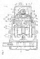
Fig. 1] Fig. 1 is a longitudinal sectional view of a gas compressor according to an embodiment of the present invention. - [
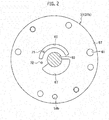
Fig. 2] Fig. 2 is a view taken along line A-A inFig. 1 and seen in the direction of the arrows. - [
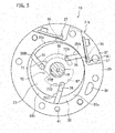
Fig. 3] Fig. 3 is a view taken along line B-B inFig. 1 and seen in the direction of the arrows. - [
Fig. 4] Fig. 4 is an enlarged view of a main portion of a compression block inFig. 3 . - [
Fig. 5] Fig. 5 is a graph showing a relation among a rotational angle of a rotor, pressure in a compression chamber, and pressure in a backpressure space, when the compression block according to the embodiment of the present invention is used. - [
Fig. 6] Fig. 6 shows a compression block used in a conventional gas compressor. - [
Fig. 7] Fig. 7 is a graph showing a relation among a rotational angle of a rotor, pressure in a compression chamber, and pressure in a backpressure space, when the conventional compression block is used. - An embodiment of the present invention will be described in detail below with reference to
Figs. 1 to 5 . - A gas compressor 1 according to the present embodiment is a vane rotary type gas compressor, and is used as a compressor in, for example, an air-conditioning system.
- As shown in
Fig. 1 , the gas compressor 1 according to the present embodiment includes a tubular (cylindrical in the present embodiment)housing 2, a compression part 3 housed in thehousing 2, amotor part 4 configured to transmit its driving power to the compression part 3, and aninverter part 5 configured to control the driving of themotor part 4. Theinverter part 5 is fixed to thehousing 2. - The
housing 2 consists mainly of a front head 7 in which an intake port (not shown) is formed and arear case 9 having a closed bottom and an opening part which is closed by the front head 7. - The compression part 3 is fixed to the inner wall surface (inner circumferential surface) 13 of the
rear case 9. Thehousing 2 defines anintake chamber 11 on one side of the compression part 3 and a discharge chamber 15 on the other side of the compression part 3. A discharge port (not shown) through which the discharge chamber 15 communicates with a refrigeration cycle is formed in an outer circumferential part of therear case 9. Anoil sump 17 which collects oil O for lubricating the compression part 3 is formed in therear case 9, in a lower part of the discharge chamber 15. - The compression part 3 includes: a compression block (block part) 19 having a
cylinder chamber 32 formed therein, anoil separator 21 fixed to thecompression block 19, arotor 23 rotatably housed in thecylinder chamber 32, vanes 25 (25A, 25B, 25C) fitted in correspondingvane grooves 75 of therotor 23 such that the vanes 25 can emerge from thevane grooves 75, and adrive shaft 27 fixed to therotor 23 to transmit the driving power to therotor 23. - The
compression block 19 consists mainly of a tubular (cylindrical in the present embodiment)cylinder block 29 and paired side blocks 31 (31a, 31b) placed on the left and right sides of thecylinder block 29 to sandwich thecylinder block 29. - As shown in
Fig. 3 , thecylinder block 29 has a bore of a distorted oval shape. Thecylinder chamber 32 is defined in this bore of thecylinder block 29 by the paired side blocks 31 sandwiching thecylinder block 29. The vanes 25 partition thecylinder chamber 32 to define compression chambers 33 (33a, 33b, 33c) in thecylinder chamber 32. More specifically, each compression chamber 33 in thecylinder chamber 32 is defined by an inner circumferential surface of the cylinder chamber 32 (the above-described bore of the cylinder block 29), an outer circumferential surface of therotor 23, and two vanes 25 adjacent in a circumferential direction of therotor 23. - The
cylinder block 29 includes anintake port 39 for taking refrigerant gas (or any gas) into the compression chambers 33, adischarge port 35 for discharging refrigerant gas compressed in the compression chambers 33, an on-offvalve 37 for opening and closing thedischarge port 35, and a cylinderoil supply channel 41 through which the frontoil supply channel 49 of theside block 31a and a secondary rearoil supply channel 59b of theside block 31b communicate with each other. - As shown in
Fig. 1 , the paired side blocks 31 include thefront side block 31a fixed to a front end portion (the left end portion inFig. 1 ) of thecylinder block 29 and therear side block 31b fixed to a rear end portion (the right end portion inFig. 1 ) of thecylinder block 29. Theoil separator 21 configured to separate oil from the refrigerant gas discharged from the compression chambers 33 is fixed to therear side block 31b. - The
front side block 31a includes an end surface (inner end surface) 43 which faces thecylinder block 29 and thecylinder chamber 32, an intake hole (not shown) which communicates with theintake port 39 of thecylinder block 29 to take in refrigerant gas from theintake chamber 11, a front bearing 47 which supports thedrive shaft 27 while allowing thedrive shaft 27 to rotate, and the frontoil supply channel 49 which communicates with the cylinderoil supply channel 41. - A pressure supply part is formed in the
inner end surface 43 of thefront side block 31a to supply pressure to backpressure spaces 77 formed behind the vanes 25. This pressure supply part includes an intermediate-pressure supply groove (intermediate-pressure supply part) 51 and a high-pressure supply groove (first high-pressure supply part) 53. The intermediate-pressure supply groove 51 supplies the backpressure spaces 77 with fluid (oil in the present embodiment) at a pressure which is higher than that of the refrigerant gas taken into the compression chambers 33 and lower than that of the refrigerant gas discharged from the compression chambers 33. The high-pressure supply groove 53 supplies the backpressure spaces 77 with oil at a high pressure which is equivalent to that of refrigerant gas discharged from the compression chambers 33. The intermediate-pressure supply groove 51 is an arc-shaped groove (chamfered groove) extending in the circumferential direction of therotor 23, and is formed at a position facing an intermediate-pressure supply groove 67 of therear side block 31b in an axial direction of thedrive shaft 27. The high-pressure supply groove 53 is an arc-shaped groove (chamfered groove) extending in the circumferential direction of therotor 23, and is formed at a position facing a high-pressure supply groove 69 of therear side block 31b in the axial direction of thedrive shaft 27. - A front
annular groove 55 in a ring shape is formed in the front bearing 47. The frontannular groove 55 communicates with one end of the frontoil supply channel 49, the other end of which communicates with the cylinderoil supply channel 41. - The
rear side block 31b includes an end surface (inner end surface) 57 which faces thecylinder block 29 and thecylinder chamber 32, adischarge hole 61 for discharging refrigerant gas compressed in the compression chambers 33, anoil supply hole 59 for taking in the oil O collected in theoil sump 17 formed in the lower part of the discharge chamber 15, arear bearing 63 configured to support thedrive shaft 27 while allowing thedrive shaft 27 to rotate, and the secondary rearoil supply channel 59b which communicates with the cylinderoil supply channel 41. - A pressure supply part configured to supply pressure to the backpressure spaces 77 behind the vanes 25 is formed in the
inner end surface 57 of therear side block 31b. The pressure supply part includes the intermediate-pressure supply groove (intermediate-pressure supply part) 67 configured to supply oil at the above-described intermediate pressure to the backpressure spaces 77, the high-pressure supply groove (high-pressure supply part) 69 configured to supply oil at the above-described high pressure to the backpressure spaces 77, and a high-pressure supply hole (second high-pressure supply part) 72 formed independently of the intermediate-pressure supply groove 67 and the high-pressure supply groove 69 and configured to supply oil at the high pressure to the backpressure spaces 77. The intermediate-pressure supply groove 67 is an arc-shaped groove (chamfered groove) extending in the circumferential direction of therotor 23, and is formed at a position facing the intermediate-pressure supply groove 51 of thefront side block 31a in the axial direction of thedrive shaft 27. The high-pressure supply groove 69 is an arc-shaped groove (chamfered groove) extending in the circumferential direction of therotor 23, and is formed at a position facing the high-pressure supply groove 53 of thefront side block 31a in the axial direction of thedrive shaft 27. - The high-pressure supply hole may be provided also to the
front side block 31a, or the intermediate-pressure supply groove, the high-pressure supply groove, and the high-pressure supply hole may be provided only to one of the inner end surfaces 43 and 57 of the paired side blocks 31. - As shown in
Fig. 2 , a high-pressure supply channel 71, at one end, opens into the high-pressure supply groove 69, and at the other end, communicates with arear communication channel 65. - The high-
pressure supply hole 72, at one end, communicates with a rearannular groove 73, and at the other end, opens onto theinner end surface 57 of therear side block 31b, at an area between the intermediate-pressure supply groove 67 and the high-pressure supply groove 69. In other words, the high-pressure supply hole 72 is formed at a position between the intermediate-pressure supply groove 67 and the high-pressure supply groove 69 in the circumferential direction of therotor 23. At this position, the high-pressure supply hole 72 communicates with the backpressure space 77 during the compression cycle in the compression chamber 33. - As described earlier, the high-
pressure supply hole 72 is formed in theinner end surface 57 of therear side block 31b, independently of the intermediate-pressure supply groove 67 and the high-pressure supply groove 69. In other words, the high-pressure supply hole 72 is formed in theinner end surface 57 at a distance from each of the intermediate-pressure supply groove 67 and the high-pressure supply groove 69. A distance h1 between the intermediate-pressure supply groove 67 and the high-pressure supply hole 72 in the circumferential direction of therotor 23 is larger (wider) than a width h2 of each backpressure space 77. A distance h3 between the high-pressure supply hole 72 and the high-pressure supply groove 69 in the circumferential direction of therotor 23 may be either larger (wider) or smaller (narrower) than the width of the backpressure space 77. - The rear
annular groove 73 in the ring shape is formed in therear bearing 63, and communicates with one end of a primary rear oil supply channel 59a, the other end of which communicates with theoil supply hole 59. The primary rear oil supply channel 59a communicates with one end of the secondary rearoil supply channel 59b which branches off from the primary rear oil supply channel 59a. The other end of the secondary rearoil supply channel 59b communicates with the cylinderoil supply channel 41. The rearannular groove 73 communicates with one end of therear communication channel 65, the other end of which communicates with the high-pressure supply channel 71. - As shown in
Figs. 3 and4 , therotor 23 is placed in such a manner that a portion of therotor 23 touches the inner wall surface (inner circumferential surface) of thecylinder chamber 32 and that the rotational center of therotor 23 does not coincide with the center of thecylinder chamber 32. Therotor 23 has thevane grooves 75 and the backpressure spaces 77 (77A, 77B, 77C) formed in thevane grooves 75 and behind the vanes 25. Thevane grooves 75 are formed in an outer circumferential portion of therotor 23 at intervals in the circumferential direction of therotor 23. - These backpressure spaces 77 open onto the left and right end surfaces of the
rotor 23. As therotor 23 rotates, each backpressure space 77 communicates with the intermediate-pressure supply grooves pressure supply hole 72 during the middle compression cycle in the compression chamber 33, and communicates with the high-pressure supply grooves - The
drive shaft 27 is fixed to therotor 23 at one end thereof and is rotatably supported by the front bearing 47 of theside block 31a and therear bearing 63 of theside block 31b. The other end of thedrive shaft 27 is fixed to amotor rotor 81 of themotor part 4. - The
motor part 4 includes astator 79 fixed to theinner wall surface 13 of therear case 9 and themotor rotor 81 placed rotatably inside thestator 79 and configured to be rotated by a magnetic force. Themotor part 4 transmits its driving power to the compression part 3 by the rotation of themotor rotor 81. - Next, operation of the gas compressor 1 according to the present embodiment is described.
- First, the
inverter part 5 performs control so that current flows through a coil wound on thestator 79 of themotor part 4. A magnetic force is generated by the current flowing through the coil, rotating themotor rotor 81 placed inside thestator 79. - The rotation of the
motor rotor 81 rotates thedrive shaft 27 whose one end is fixed to themotor rotor 81, and in turn rotates therotor 23 fixed to the other end of thedrive shaft 27. - As the
rotor 23 rotates, refrigerant gas flows into theintake chamber 11. The refrigerant gas flows from theintake chamber 11 into each compression chamber 33, through the intake hole (not shown) of thefront side block 31a and theintake port 39 of the cylinder block 29 (intake cycle). The refrigerant gas taken into the compression chamber 33 is compressed as therotor 23 rotates (compression cycle). - The refrigerant gas compressed in the compression chamber 33 pushes the on-off
valve 37 open and is discharged from the compression chamber 33 through the discharge port 35 (discharge cycle), and is then discharged to the discharge chamber 15 through thedischarge hole 61 and theoil separator 21 which separates oil from the refrigerant gas. The resultant refrigerant gas is then discharged to the refrigeration cycle (not shown) through the discharge port (not shown), and the oil is collected in theoil sump 17 formed in the lower part of the discharge chamber 15. - The oil O collected in the
oil sump 17 in the lower part of the discharge chamber 15 enters the primary rear oil supply channel 59a from theoil supply hole 59, and is supplied to the rearannular groove 73. - The high-pressure oil supplied to the rear
annular groove 73 is then supplied to the intermediate-pressure supply groove 67 by passing through a space between thedrive shaft 27 and therear bearing 63. By the time the oil is supplied to the intermediate-pressure supply groove 67, the oil is at an intermediate pressure by being squeezed between thedrive shaft 27 and therear bearing 63, the intermediate pressure being higher than that of the refrigerant gas taken into the compression chamber 33 (intake pressure) and lower than that of the refrigerant gas discharged from the compression chamber 33 (discharge pressure). - The intermediate-pressure oil supplied to the intermediate-
pressure supply groove 67 of therear side block 31b is, as shown inFig. 3 , supplied to the backpressure space 77 in the intake cycle and the early compression cycle in the compression chamber 33, so that intermediate pressure is supplied to the back of the vane 25 to cause the vane 25 to protrude from thevane groove 75. - The high-pressure oil supplied to the rear
annular groove 73 is also supplied to the high-pressure supply groove 69 by passing through therear communication channel 65 and the high-pressure supply channel 71. - The high-pressure oil supplied to the high-
pressure supply groove 69 of therear side block 31b is, as shown inFig. 3 , supplied to the backpressure space 77 in the late compression cycle and the discharge cycle in the compression chamber 33, so that high pressure is supplied to the back of the vane 25 to cause the vane 25 to protrude from thevane groove 75. The high-pressure supply groove 69 of therear side block 31b communicates with the high-pressure supply groove 53 of thefront side block 31a through the backpressure spaces 77, so that the backpressure spaces 77 are supplied with the high-pressure oil from the high-pressure supply groove 53, as well. - The high-pressure oil supplied to the rear
annular groove 73 is also supplied to the high-pressure supply hole 72 opening onto theinner end surface 57 of therear side block 31b. - The high-pressure oil supplied to the high-
pressure supply hole 72 of therear side block 31b is, as shown inFig. 3 , supplied to the backpressure space 77 in the middle compression cycle in the compression chamber 33, so that high pressure is supplied to the back of the vane 25 before the backpressure space 77 communicates with the high-pressure supply groove 69. - The oil O collected in the
oil sump 17 formed in the lower part of the discharge chamber 15 enters the primary rear oil supply channel 59a from theoil supply hole 59 of therear side block 31b, passes through the secondary rearoil supply channel 59b, the cylinderoil supply channel 41, and the frontoil supply channel 49, and is supplied to the frontannular groove 55. - The high-pressure oil supplied to the front
annular groove 55 passes through a space between thedrive shaft 27 and the front bearing 47, and is supplied to the intermediate-pressure supply groove 51. By the time the oil is supplied to the intermediate-pressure supply groove 51, the oil is at an intermediate pressure by being squeezed between thedrive shaft 27 and the front bearing 47. - The intermediate-pressure oil supplied to the intermediate-
pressure supply groove 51 of thefront side block 31a is, as shown inFig. 3 , supplied to the backpressure space 77 in the intake cycle and the early compression cycle in the compression chamber 33, so that intermediate pressure is supplied to the back of the vane 25 to cause the vane 25 to protrude from thevane groove 75. - According to the present invention, the high-
pressure supply hole 72 formed between the intermediate-pressure supply groove 67 and the high-pressure supply groove 69 independently of the high-pressure supply groove 69 enables the backpressure space 77 to be supplied with high pressure before the backpressure space 77 communicates with the high-pressure supply groove 69. Thus, by the time the backpressure space 77 communicates with the high-pressure supply groove 69, the backpressure space 77 is already at high pressure. Chattering is thereby prevented. - As shown in
Fig. 5 , when two backpressure spaces 77 adjacent in the circumferential direction of therotor 23 communicate with the high-pressure supply groove 69 simultaneously, high pressure is supplied to thebackpressure space 77B before thebackpressure space 77B communicates with the high-pressure supply groove 69. Thus, pressure in the rotationally-upstream backpressure space 77A does not drop even after the rotationally-downstream backpressure space 77B communicates with the high-pressure supply groove 69. Chattering is thereby prevented. - The distance h1 between the intermediate-
pressure supply groove 67 and the high-pressure supply hole 72 in the circumferential direction of therotor 23 is larger (wider) than the width h2 of each backpressure space 77. Thus, the intermediate-pressure supply groove 67 and the high-pressure supply hole 72 do not communicate with each other through the backpressure space 77. This ensures that the backpressure space 77 is supplied with high pressure through the high-pressure supply hole 72. - The present application claims the priority from Japanese Patent Application No.
2014-002173 filed on January 9, 2014 - The present invention has been described using the embodiment. However, as it is obvious to those skilled in the art, the present invention is not limited to what has been described above and can be modified or improved variously.
- According to the present invention, a second high-pressure supply part is formed between an intermediate-pressure supply part and a first high-pressure supply part, independently of the first high-pressure supply part. This enables a backpressure space to be supplied with high pressure before the backpressure space communicates with the first high-pressure supply part. Thus, high pressure can be maintained in the first high-pressure supply part to prevent pressure drop in the backpressure space behind a vane. The high pressure maintained in the first high-pressure supply part prevents the vane from being pushed back to its vane groove, and therefore prevents chattering.
-
- 1
- gas compressor
- 19
- compression block (block part)
- 23
- rotor
- 25
- vane
- 32
- cylinder chamber
- 33
- compression chamber
- 51
- intermediate-pressure supply groove (intermediate-pressure supply part)
- 53
- high-pressure supply groove (first high-pressure supply part)
- 67
- intermediate-pressure supply groove (intermediate-pressure supply part)
- 69
- high-pressure supply groove (first high-pressure supply part)
- 72
- high-pressure supply hole (second high-pressure supply part)
- 77
- backpressure space
Claims (3)
- A gas compressor comprising:a block part inside which a cylinder chamber is formed;a rotor rotatably housed in the cylinder chamber; anda plurality of vanes provided in an outer circumferential portion of the rotor at an interval in a circumferential direction of the rotor, the vanes being capable of emerging from the outer circumferential portion,an inner circumferential surface of the cylinder chamber, an outer circumferential surface of the rotor, and each two of the vanes adjacent in the circumferential direction of the rotor defining a compression chamber inside the cylinder chamber,the block part having a pressure supply part configured to supply pressure to backpressure spaces formed behind the respective vanes, whereinthe pressure supply part hasan intermediate-pressure supply part which communicates with each backpressure space from an intake cycle to a compression cycle in the compression chamber,a first high-pressure supply part which communicates with the backpressure space from the compression cycle to a discharge cycle in the compression chamber, anda second high-pressure supply part which is formed between the intermediate-pressure supply part and the first high-pressure supply part independently of the first high-pressure supply part and which communicates with the backpressure space in a middle of the compression cycle in the compression chamber.
- The gas compressor according to claim 1, wherein the first high-pressure supply part is formed over an area where the first high-pressure supply part communicates simultaneously with two of the backpressure spaces adjacent in the circumferential direction of the rotor.
- The gas compressor according to claim 1 or 2, wherein the block part has a tubular cylinder block and paired side blocks placed on both sides of the cylinder block, and
the intermediate-pressure supply part, the first high-pressure supply part, and the second high-pressure supply part are formed in an inner end surface of at least one of the paired side blocks.
Applications Claiming Priority (2)
| Application Number | Priority Date | Filing Date | Title |
|---|---|---|---|
| JP2014002173 | 2014-01-09 | ||
| PCT/JP2014/082229 WO2015104930A1 (en) | 2014-01-09 | 2014-12-05 | Gas compressor |
Publications (3)
| Publication Number | Publication Date |
|---|---|
| EP3093494A4 EP3093494A4 (en) | 2016-11-16 |
| EP3093494A1 true EP3093494A1 (en) | 2016-11-16 |
| EP3093494B1 EP3093494B1 (en) | 2018-02-07 |
Family
ID=53523768
Family Applications (1)
| Application Number | Title | Priority Date | Filing Date |
|---|---|---|---|
| EP14878173.5A Not-in-force EP3093494B1 (en) | 2014-01-09 | 2014-12-05 | Gas compressor |
Country Status (5)
| Country | Link |
|---|---|
| US (1) | US9784273B2 (en) |
| EP (1) | EP3093494B1 (en) |
| JP (1) | JP5879010B2 (en) |
| CN (1) | CN105899810B (en) |
| WO (1) | WO2015104930A1 (en) |
Cited By (1)
| Publication number | Priority date | Publication date | Assignee | Title |
|---|---|---|---|---|
| CN110537021A (en) * | 2017-04-22 | 2019-12-03 | 株式会社不二越 | vane pump |
Families Citing this family (12)
| Publication number | Priority date | Publication date | Assignee | Title |
|---|---|---|---|---|
| DE102016112555B4 (en) * | 2016-07-08 | 2021-11-25 | Pierburg Pump Technology Gmbh | Automotive auxiliary equipment vacuum pump |
| EP3315782A1 (en) * | 2016-10-25 | 2018-05-02 | Entecnia Consulting, S.L.U. | Vacuum pump |
| CN110234882B (en) * | 2017-02-01 | 2021-03-09 | 皮尔伯格泵技术有限责任公司 | Vane air pump |
| JP6717232B2 (en) * | 2017-02-28 | 2020-07-01 | 株式会社豊田自動織機 | Vane compressor |
| KR102390684B1 (en) * | 2017-06-22 | 2022-04-26 | 엘지전자 주식회사 | Compressor having round part placed near outlet port |
| JP6825530B2 (en) * | 2017-09-29 | 2021-02-03 | 株式会社豊田自動織機 | Vane compressor |
| KR101954533B1 (en) * | 2017-10-30 | 2019-03-05 | 엘지전자 주식회사 | Rotary compressor |
| KR102180179B1 (en) * | 2018-11-09 | 2020-11-18 | 엘지전자 주식회사 | Vain rotary compressor |
| KR102223283B1 (en) * | 2018-11-16 | 2021-03-05 | 엘지전자 주식회사 | Vain rotary compressor |
| KR102349747B1 (en) * | 2020-05-22 | 2022-01-11 | 엘지전자 주식회사 | Rotary compressor |
| KR102378399B1 (en) | 2020-07-03 | 2022-03-24 | 엘지전자 주식회사 | Rotary compressor |
| KR102476697B1 (en) | 2021-02-01 | 2022-12-12 | 엘지전자 주식회사 | Rotary compressor |
Family Cites Families (13)
| Publication number | Priority date | Publication date | Assignee | Title |
|---|---|---|---|---|
| JPS5814491U (en) | 1981-07-22 | 1983-01-29 | ダイキン工業株式会社 | multi vane compressor |
| US4455129A (en) * | 1981-05-19 | 1984-06-19 | Daikin Kogyo Co., Ltd. | Multi-vane type compressor |
| US4810177A (en) * | 1982-06-18 | 1989-03-07 | Diesel Kiki Co., Ltd. | Vane compressor with vane back pressure adjustment |
| JPH01141391U (en) | 1988-03-23 | 1989-09-28 | ||
| JPH02248682A (en) | 1989-03-20 | 1990-10-04 | Diesel Kiki Co Ltd | Vane type compressor |
| JP3792578B2 (en) * | 2001-02-28 | 2006-07-05 | カルソニックコンプレッサー株式会社 | Gas compressor |
| JP2003113787A (en) * | 2001-10-03 | 2003-04-18 | Seiko Instruments Inc | Gas compressor |
| JP4060149B2 (en) | 2002-08-30 | 2008-03-12 | カルソニックコンプレッサー株式会社 | Gas compressor |
| US9173604B2 (en) | 2010-03-19 | 2015-11-03 | Sharp Kabushiki Kaisha | Measurement device, measurement method, measurement result processing device, measurement system, measurement result processing method, control program, and recording medium |
| CN102971538B (en) * | 2010-03-31 | 2017-03-15 | 纳博特斯克汽车株式会社 | Vacuum pump |
| US9751384B2 (en) | 2011-11-24 | 2017-09-05 | Calsonic Kansei Corporation | Gas compressor with discharge section and sub-discharge section |
| JP5826686B2 (en) | 2012-03-16 | 2015-12-02 | カルソニックカンセイ株式会社 | Gas compressor |
| JP5913199B2 (en) * | 2012-06-05 | 2016-04-27 | カルソニックカンセイ株式会社 | Gas compressor |
-
2014
- 2014-12-05 CN CN201480072588.XA patent/CN105899810B/en not_active Expired - Fee Related
- 2014-12-05 EP EP14878173.5A patent/EP3093494B1/en not_active Not-in-force
- 2014-12-05 WO PCT/JP2014/082229 patent/WO2015104930A1/en not_active Ceased
- 2014-12-05 US US15/110,519 patent/US9784273B2/en not_active Expired - Fee Related
- 2014-12-05 JP JP2015519664A patent/JP5879010B2/en not_active Expired - Fee Related
Cited By (2)
| Publication number | Priority date | Publication date | Assignee | Title |
|---|---|---|---|---|
| CN110537021A (en) * | 2017-04-22 | 2019-12-03 | 株式会社不二越 | vane pump |
| CN110537021B (en) * | 2017-04-22 | 2021-04-30 | 株式会社不二越 | Vane pump |
Also Published As
| Publication number | Publication date |
|---|---|
| EP3093494A4 (en) | 2016-11-16 |
| JP5879010B2 (en) | 2016-03-08 |
| CN105899810A (en) | 2016-08-24 |
| US9784273B2 (en) | 2017-10-10 |
| WO2015104930A1 (en) | 2015-07-16 |
| JPWO2015104930A1 (en) | 2017-03-23 |
| CN105899810B (en) | 2017-08-22 |
| EP3093494B1 (en) | 2018-02-07 |
| US20160333877A1 (en) | 2016-11-17 |
Similar Documents
| Publication | Publication Date | Title |
|---|---|---|
| EP3093494B1 (en) | Gas compressor | |
| EP3252313B1 (en) | Sliding vane compressor and exhaust structure thereof | |
| EP2246572B1 (en) | Screw compressor | |
| AU2008205992B2 (en) | Compressor | |
| JP2013241851A (en) | Gas compressor | |
| EP2803863B1 (en) | Vane-type compressor | |
| JP2015129475A (en) | Electric compressor | |
| EP3184822B1 (en) | Rotary compressor and refrigeration cycle device | |
| JP6402648B2 (en) | Vane type compressor | |
| EP3239530A1 (en) | Gas compressor | |
| EP2520802A1 (en) | Lubricating oil supply structure of vane-type compressor | |
| JP6197679B2 (en) | Scroll compressor | |
| KR102182348B1 (en) | Hermetic compressor and refrigeration cycle unit | |
| CN108691749A (en) | Check-valves and compressor | |
| EP3450763B1 (en) | Screw compressor | |
| JP5825367B2 (en) | Vane type compressor | |
| CN104912796A (en) | Compressor | |
| JP2002062020A (en) | refrigerator | |
| US20090074602A1 (en) | Rotary type fluid machine | |
| JP5727348B2 (en) | Gas compressor | |
| CN110388319B (en) | Screw compressor with synchronous economizer port | |
| CN109312749B (en) | Rotary vane compressor and method of operating and manufacturing the same | |
| JP5817605B2 (en) | Scroll compressor | |
| JP5878970B1 (en) | Gas compressor | |
| KR101954533B1 (en) | Rotary compressor |
Legal Events
| Date | Code | Title | Description |
|---|---|---|---|
| PUAI | Public reference made under article 153(3) epc to a published international application that has entered the european phase |
Free format text: ORIGINAL CODE: 0009012 |
|
| 17P | Request for examination filed |
Effective date: 20160713 |
|
| A4 | Supplementary search report drawn up and despatched |
Effective date: 20161005 |
|
| AK | Designated contracting states |
Kind code of ref document: A1 Designated state(s): AL AT BE BG CH CY CZ DE DK EE ES FI FR GB GR HR HU IE IS IT LI LT LU LV MC MK MT NL NO PL PT RO RS SE SI SK SM TR |
|
| AX | Request for extension of the european patent |
Extension state: BA ME |
|
| GRAP | Despatch of communication of intention to grant a patent |
Free format text: ORIGINAL CODE: EPIDOSNIGR1 |
|
| RIC1 | Information provided on ipc code assigned before grant |
Ipc: F04C 29/02 20060101ALI20170216BHEP Ipc: F04C 18/344 20060101AFI20170216BHEP Ipc: F04C 29/00 20060101ALI20170216BHEP Ipc: F01C 21/08 20060101ALI20170216BHEP |
|
| DAX | Request for extension of the european patent (deleted) | ||
| INTG | Intention to grant announced |
Effective date: 20170317 |
|
| GRAJ | Information related to disapproval of communication of intention to grant by the applicant or resumption of examination proceedings by the epo deleted |
Free format text: ORIGINAL CODE: EPIDOSDIGR1 |
|
| INTC | Intention to grant announced (deleted) | ||
| GRAP | Despatch of communication of intention to grant a patent |
Free format text: ORIGINAL CODE: EPIDOSNIGR1 |
|
| INTG | Intention to grant announced |
Effective date: 20170725 |
|
| GRAS | Grant fee paid |
Free format text: ORIGINAL CODE: EPIDOSNIGR3 |
|
| GRAA | (expected) grant |
Free format text: ORIGINAL CODE: 0009210 |
|
| AK | Designated contracting states |
Kind code of ref document: B1 Designated state(s): AL AT BE BG CH CY CZ DE DK EE ES FI FR GB GR HR HU IE IS IT LI LT LU LV MC MK MT NL NO PL PT RO RS SE SI SK SM TR |
|
| REG | Reference to a national code |
Ref country code: GB Ref legal event code: FG4D |
|
| REG | Reference to a national code |
Ref country code: AT Ref legal event code: REF Ref document number: 968927 Country of ref document: AT Kind code of ref document: T Effective date: 20180215 Ref country code: CH Ref legal event code: EP |
|
| REG | Reference to a national code |
Ref country code: IE Ref legal event code: FG4D |
|
| REG | Reference to a national code |
Ref country code: DE Ref legal event code: R096 Ref document number: 602014020845 Country of ref document: DE |
|
| REG | Reference to a national code |
Ref country code: NL Ref legal event code: MP Effective date: 20180207 |
|
| REG | Reference to a national code |
Ref country code: AT Ref legal event code: MK05 Ref document number: 968927 Country of ref document: AT Kind code of ref document: T Effective date: 20180207 |
|
| PG25 | Lapsed in a contracting state [announced via postgrant information from national office to epo] |
Ref country code: LT Free format text: LAPSE BECAUSE OF FAILURE TO SUBMIT A TRANSLATION OF THE DESCRIPTION OR TO PAY THE FEE WITHIN THE PRESCRIBED TIME-LIMIT Effective date: 20180207 Ref country code: CY Free format text: LAPSE BECAUSE OF FAILURE TO SUBMIT A TRANSLATION OF THE DESCRIPTION OR TO PAY THE FEE WITHIN THE PRESCRIBED TIME-LIMIT Effective date: 20180207 Ref country code: NO Free format text: LAPSE BECAUSE OF FAILURE TO SUBMIT A TRANSLATION OF THE DESCRIPTION OR TO PAY THE FEE WITHIN THE PRESCRIBED TIME-LIMIT Effective date: 20180507 Ref country code: NL Free format text: LAPSE BECAUSE OF FAILURE TO SUBMIT A TRANSLATION OF THE DESCRIPTION OR TO PAY THE FEE WITHIN THE PRESCRIBED TIME-LIMIT Effective date: 20180207 Ref country code: FI Free format text: LAPSE BECAUSE OF FAILURE TO SUBMIT A TRANSLATION OF THE DESCRIPTION OR TO PAY THE FEE WITHIN THE PRESCRIBED TIME-LIMIT Effective date: 20180207 Ref country code: ES Free format text: LAPSE BECAUSE OF FAILURE TO SUBMIT A TRANSLATION OF THE DESCRIPTION OR TO PAY THE FEE WITHIN THE PRESCRIBED TIME-LIMIT Effective date: 20180207 Ref country code: HR Free format text: LAPSE BECAUSE OF FAILURE TO SUBMIT A TRANSLATION OF THE DESCRIPTION OR TO PAY THE FEE WITHIN THE PRESCRIBED TIME-LIMIT Effective date: 20180207 |
|
| PG25 | Lapsed in a contracting state [announced via postgrant information from national office to epo] |
Ref country code: RS Free format text: LAPSE BECAUSE OF FAILURE TO SUBMIT A TRANSLATION OF THE DESCRIPTION OR TO PAY THE FEE WITHIN THE PRESCRIBED TIME-LIMIT Effective date: 20180207 Ref country code: LV Free format text: LAPSE BECAUSE OF FAILURE TO SUBMIT A TRANSLATION OF THE DESCRIPTION OR TO PAY THE FEE WITHIN THE PRESCRIBED TIME-LIMIT Effective date: 20180207 Ref country code: SE Free format text: LAPSE BECAUSE OF FAILURE TO SUBMIT A TRANSLATION OF THE DESCRIPTION OR TO PAY THE FEE WITHIN THE PRESCRIBED TIME-LIMIT Effective date: 20180207 Ref country code: BG Free format text: LAPSE BECAUSE OF FAILURE TO SUBMIT A TRANSLATION OF THE DESCRIPTION OR TO PAY THE FEE WITHIN THE PRESCRIBED TIME-LIMIT Effective date: 20180507 Ref country code: AT Free format text: LAPSE BECAUSE OF FAILURE TO SUBMIT A TRANSLATION OF THE DESCRIPTION OR TO PAY THE FEE WITHIN THE PRESCRIBED TIME-LIMIT Effective date: 20180207 Ref country code: IS Free format text: LAPSE BECAUSE OF FAILURE TO SUBMIT A TRANSLATION OF THE DESCRIPTION OR TO PAY THE FEE WITHIN THE PRESCRIBED TIME-LIMIT Effective date: 20180607 Ref country code: GR Free format text: LAPSE BECAUSE OF FAILURE TO SUBMIT A TRANSLATION OF THE DESCRIPTION OR TO PAY THE FEE WITHIN THE PRESCRIBED TIME-LIMIT Effective date: 20180508 Ref country code: PL Free format text: LAPSE BECAUSE OF FAILURE TO SUBMIT A TRANSLATION OF THE DESCRIPTION OR TO PAY THE FEE WITHIN THE PRESCRIBED TIME-LIMIT Effective date: 20180207 |
|
| PG25 | Lapsed in a contracting state [announced via postgrant information from national office to epo] |
Ref country code: IT Free format text: LAPSE BECAUSE OF FAILURE TO SUBMIT A TRANSLATION OF THE DESCRIPTION OR TO PAY THE FEE WITHIN THE PRESCRIBED TIME-LIMIT Effective date: 20180207 Ref country code: EE Free format text: LAPSE BECAUSE OF FAILURE TO SUBMIT A TRANSLATION OF THE DESCRIPTION OR TO PAY THE FEE WITHIN THE PRESCRIBED TIME-LIMIT Effective date: 20180207 Ref country code: AL Free format text: LAPSE BECAUSE OF FAILURE TO SUBMIT A TRANSLATION OF THE DESCRIPTION OR TO PAY THE FEE WITHIN THE PRESCRIBED TIME-LIMIT Effective date: 20180207 |
|
| REG | Reference to a national code |
Ref country code: DE Ref legal event code: R097 Ref document number: 602014020845 Country of ref document: DE |
|
| PG25 | Lapsed in a contracting state [announced via postgrant information from national office to epo] |
Ref country code: SK Free format text: LAPSE BECAUSE OF FAILURE TO SUBMIT A TRANSLATION OF THE DESCRIPTION OR TO PAY THE FEE WITHIN THE PRESCRIBED TIME-LIMIT Effective date: 20180207 Ref country code: SM Free format text: LAPSE BECAUSE OF FAILURE TO SUBMIT A TRANSLATION OF THE DESCRIPTION OR TO PAY THE FEE WITHIN THE PRESCRIBED TIME-LIMIT Effective date: 20180207 Ref country code: DK Free format text: LAPSE BECAUSE OF FAILURE TO SUBMIT A TRANSLATION OF THE DESCRIPTION OR TO PAY THE FEE WITHIN THE PRESCRIBED TIME-LIMIT Effective date: 20180207 Ref country code: CZ Free format text: LAPSE BECAUSE OF FAILURE TO SUBMIT A TRANSLATION OF THE DESCRIPTION OR TO PAY THE FEE WITHIN THE PRESCRIBED TIME-LIMIT Effective date: 20180207 |
|
| PLBE | No opposition filed within time limit |
Free format text: ORIGINAL CODE: 0009261 |
|
| STAA | Information on the status of an ep patent application or granted ep patent |
Free format text: STATUS: NO OPPOSITION FILED WITHIN TIME LIMIT |
|
| 26N | No opposition filed |
Effective date: 20181108 |
|
| PG25 | Lapsed in a contracting state [announced via postgrant information from national office to epo] |
Ref country code: SI Free format text: LAPSE BECAUSE OF FAILURE TO SUBMIT A TRANSLATION OF THE DESCRIPTION OR TO PAY THE FEE WITHIN THE PRESCRIBED TIME-LIMIT Effective date: 20180207 |
|
| PGFP | Annual fee paid to national office [announced via postgrant information from national office to epo] |
Ref country code: FR Payment date: 20181221 Year of fee payment: 5 |
|
| PGFP | Annual fee paid to national office [announced via postgrant information from national office to epo] |
Ref country code: DE Payment date: 20181221 Year of fee payment: 5 |
|
| REG | Reference to a national code |
Ref country code: CH Ref legal event code: PL |
|
| GBPC | Gb: european patent ceased through non-payment of renewal fee |
Effective date: 20181205 |
|
| PG25 | Lapsed in a contracting state [announced via postgrant information from national office to epo] |
Ref country code: LU Free format text: LAPSE BECAUSE OF NON-PAYMENT OF DUE FEES Effective date: 20181205 Ref country code: MC Free format text: LAPSE BECAUSE OF FAILURE TO SUBMIT A TRANSLATION OF THE DESCRIPTION OR TO PAY THE FEE WITHIN THE PRESCRIBED TIME-LIMIT Effective date: 20180207 |
|
| REG | Reference to a national code |
Ref country code: IE Ref legal event code: MM4A |
|
| REG | Reference to a national code |
Ref country code: BE Ref legal event code: MM Effective date: 20181231 |
|
| PG25 | Lapsed in a contracting state [announced via postgrant information from national office to epo] |
Ref country code: IE Free format text: LAPSE BECAUSE OF NON-PAYMENT OF DUE FEES Effective date: 20181205 |
|
| PG25 | Lapsed in a contracting state [announced via postgrant information from national office to epo] |
Ref country code: BE Free format text: LAPSE BECAUSE OF NON-PAYMENT OF DUE FEES Effective date: 20181231 |
|
| PG25 | Lapsed in a contracting state [announced via postgrant information from national office to epo] |
Ref country code: LI Free format text: LAPSE BECAUSE OF NON-PAYMENT OF DUE FEES Effective date: 20181231 Ref country code: CH Free format text: LAPSE BECAUSE OF NON-PAYMENT OF DUE FEES Effective date: 20181231 Ref country code: GB Free format text: LAPSE BECAUSE OF NON-PAYMENT OF DUE FEES Effective date: 20181205 |
|
| PG25 | Lapsed in a contracting state [announced via postgrant information from national office to epo] |
Ref country code: MT Free format text: LAPSE BECAUSE OF NON-PAYMENT OF DUE FEES Effective date: 20181205 |
|
| PG25 | Lapsed in a contracting state [announced via postgrant information from national office to epo] |
Ref country code: TR Free format text: LAPSE BECAUSE OF FAILURE TO SUBMIT A TRANSLATION OF THE DESCRIPTION OR TO PAY THE FEE WITHIN THE PRESCRIBED TIME-LIMIT Effective date: 20180207 |
|
| PG25 | Lapsed in a contracting state [announced via postgrant information from national office to epo] |
Ref country code: PT Free format text: LAPSE BECAUSE OF FAILURE TO SUBMIT A TRANSLATION OF THE DESCRIPTION OR TO PAY THE FEE WITHIN THE PRESCRIBED TIME-LIMIT Effective date: 20180207 |
|
| PG25 | Lapsed in a contracting state [announced via postgrant information from national office to epo] |
Ref country code: MK Free format text: LAPSE BECAUSE OF NON-PAYMENT OF DUE FEES Effective date: 20180207 Ref country code: RO Free format text: LAPSE BECAUSE OF FAILURE TO SUBMIT A TRANSLATION OF THE DESCRIPTION OR TO PAY THE FEE WITHIN THE PRESCRIBED TIME-LIMIT Effective date: 20180207 Ref country code: HU Free format text: LAPSE BECAUSE OF FAILURE TO SUBMIT A TRANSLATION OF THE DESCRIPTION OR TO PAY THE FEE WITHIN THE PRESCRIBED TIME-LIMIT; INVALID AB INITIO Effective date: 20141205 |
|
| REG | Reference to a national code |
Ref country code: DE Ref legal event code: R119 Ref document number: 602014020845 Country of ref document: DE |
|
| PG25 | Lapsed in a contracting state [announced via postgrant information from national office to epo] |
Ref country code: DE Free format text: LAPSE BECAUSE OF NON-PAYMENT OF DUE FEES Effective date: 20200701 |
|
| PG25 | Lapsed in a contracting state [announced via postgrant information from national office to epo] |
Ref country code: FR Free format text: LAPSE BECAUSE OF NON-PAYMENT OF DUE FEES Effective date: 20191231 |