EP3093483A1 - Engine starting device - Google Patents
Engine starting device Download PDFInfo
- Publication number
- EP3093483A1 EP3093483A1 EP14878047.1A EP14878047A EP3093483A1 EP 3093483 A1 EP3093483 A1 EP 3093483A1 EP 14878047 A EP14878047 A EP 14878047A EP 3093483 A1 EP3093483 A1 EP 3093483A1
- Authority
- EP
- European Patent Office
- Prior art keywords
- engine
- starter motor
- starter
- signal
- energization
- Prior art date
- Legal status (The legal status is an assumption and is not a legal conclusion. Google has not performed a legal analysis and makes no representation as to the accuracy of the status listed.)
- Granted
Links
- 239000007858 starting material Substances 0.000 claims abstract description 171
- 239000004065 semiconductor Substances 0.000 claims description 4
- 238000010586 diagram Methods 0.000 description 16
- 238000000034 method Methods 0.000 description 13
- 230000007246 mechanism Effects 0.000 description 9
- 239000000446 fuel Substances 0.000 description 8
- 230000005540 biological transmission Effects 0.000 description 5
- 238000004891 communication Methods 0.000 description 5
- 230000007613 environmental effect Effects 0.000 description 4
- 230000000694 effects Effects 0.000 description 3
- 238000012545 processing Methods 0.000 description 3
- 238000002347 injection Methods 0.000 description 2
- 239000007924 injection Substances 0.000 description 2
- 238000010992 reflux Methods 0.000 description 2
- 230000004044 response Effects 0.000 description 2
- 239000000243 solution Substances 0.000 description 2
- 230000008859 change Effects 0.000 description 1
- 238000002485 combustion reaction Methods 0.000 description 1
- 230000003247 decreasing effect Effects 0.000 description 1
- 238000001514 detection method Methods 0.000 description 1
- 230000007257 malfunction Effects 0.000 description 1
- 238000012986 modification Methods 0.000 description 1
- 230000004048 modification Effects 0.000 description 1
- 238000012544 monitoring process Methods 0.000 description 1
- 108090000623 proteins and genes Proteins 0.000 description 1
- 230000001360 synchronised effect Effects 0.000 description 1
Images


Classifications
-
- F—MECHANICAL ENGINEERING; LIGHTING; HEATING; WEAPONS; BLASTING
- F02—COMBUSTION ENGINES; HOT-GAS OR COMBUSTION-PRODUCT ENGINE PLANTS
- F02N—STARTING OF COMBUSTION ENGINES; STARTING AIDS FOR SUCH ENGINES, NOT OTHERWISE PROVIDED FOR
- F02N11/00—Starting of engines by means of electric motors
- F02N11/08—Circuits or control means specially adapted for starting of engines
- F02N11/0814—Circuits or control means specially adapted for starting of engines comprising means for controlling automatic idle-start-stop
- F02N11/0844—Circuits or control means specially adapted for starting of engines comprising means for controlling automatic idle-start-stop with means for restarting the engine directly after an engine stop request, e.g. caused by change of driver mind
-
- F—MECHANICAL ENGINEERING; LIGHTING; HEATING; WEAPONS; BLASTING
- F02—COMBUSTION ENGINES; HOT-GAS OR COMBUSTION-PRODUCT ENGINE PLANTS
- F02N—STARTING OF COMBUSTION ENGINES; STARTING AIDS FOR SUCH ENGINES, NOT OTHERWISE PROVIDED FOR
- F02N11/00—Starting of engines by means of electric motors
- F02N11/10—Safety devices
- F02N11/101—Safety devices for preventing engine starter actuation or engagement
-
- F—MECHANICAL ENGINEERING; LIGHTING; HEATING; WEAPONS; BLASTING
- F02—COMBUSTION ENGINES; HOT-GAS OR COMBUSTION-PRODUCT ENGINE PLANTS
- F02N—STARTING OF COMBUSTION ENGINES; STARTING AIDS FOR SUCH ENGINES, NOT OTHERWISE PROVIDED FOR
- F02N11/00—Starting of engines by means of electric motors
- F02N11/08—Circuits or control means specially adapted for starting of engines
- F02N11/0851—Circuits or control means specially adapted for starting of engines characterised by means for controlling the engagement or disengagement between engine and starter, e.g. meshing of pinion and engine gear
-
- F—MECHANICAL ENGINEERING; LIGHTING; HEATING; WEAPONS; BLASTING
- F02—COMBUSTION ENGINES; HOT-GAS OR COMBUSTION-PRODUCT ENGINE PLANTS
- F02N—STARTING OF COMBUSTION ENGINES; STARTING AIDS FOR SUCH ENGINES, NOT OTHERWISE PROVIDED FOR
- F02N11/00—Starting of engines by means of electric motors
- F02N11/08—Circuits or control means specially adapted for starting of engines
- F02N11/087—Details of the switching means in starting circuits, e.g. relays or electronic switches
-
- F—MECHANICAL ENGINEERING; LIGHTING; HEATING; WEAPONS; BLASTING
- F02—COMBUSTION ENGINES; HOT-GAS OR COMBUSTION-PRODUCT ENGINE PLANTS
- F02N—STARTING OF COMBUSTION ENGINES; STARTING AIDS FOR SUCH ENGINES, NOT OTHERWISE PROVIDED FOR
- F02N15/00—Other power-operated starting apparatus; Component parts, details, or accessories, not provided for in, or of interest apart from groups F02N5/00 - F02N13/00
- F02N15/02—Gearing between starting-engines and started engines; Engagement or disengagement thereof
- F02N15/04—Gearing between starting-engines and started engines; Engagement or disengagement thereof the gearing including disengaging toothed gears
- F02N15/06—Gearing between starting-engines and started engines; Engagement or disengagement thereof the gearing including disengaging toothed gears the toothed gears being moved by axial displacement
- F02N15/067—Gearing between starting-engines and started engines; Engagement or disengagement thereof the gearing including disengaging toothed gears the toothed gears being moved by axial displacement the starter comprising an electro-magnetically actuated lever
-
- F—MECHANICAL ENGINEERING; LIGHTING; HEATING; WEAPONS; BLASTING
- F02—COMBUSTION ENGINES; HOT-GAS OR COMBUSTION-PRODUCT ENGINE PLANTS
- F02N—STARTING OF COMBUSTION ENGINES; STARTING AIDS FOR SUCH ENGINES, NOT OTHERWISE PROVIDED FOR
- F02N2200/00—Parameters used for control of starting apparatus
- F02N2200/04—Parameters used for control of starting apparatus said parameters being related to the starter motor
- F02N2200/043—Starter voltage
-
- F—MECHANICAL ENGINEERING; LIGHTING; HEATING; WEAPONS; BLASTING
- F02—COMBUSTION ENGINES; HOT-GAS OR COMBUSTION-PRODUCT ENGINE PLANTS
- F02N—STARTING OF COMBUSTION ENGINES; STARTING AIDS FOR SUCH ENGINES, NOT OTHERWISE PROVIDED FOR
- F02N2250/00—Problems related to engine starting or engine's starting apparatus
- F02N2250/04—Reverse rotation of the engine
-
- F—MECHANICAL ENGINEERING; LIGHTING; HEATING; WEAPONS; BLASTING
- F02—COMBUSTION ENGINES; HOT-GAS OR COMBUSTION-PRODUCT ENGINE PLANTS
- F02N—STARTING OF COMBUSTION ENGINES; STARTING AIDS FOR SUCH ENGINES, NOT OTHERWISE PROVIDED FOR
- F02N2300/00—Control related aspects of engine starting
- F02N2300/10—Control related aspects of engine starting characterised by the control output, i.e. means or parameters used as a control output or target
- F02N2300/104—Control of the starter motor torque
-
- F—MECHANICAL ENGINEERING; LIGHTING; HEATING; WEAPONS; BLASTING
- F02—COMBUSTION ENGINES; HOT-GAS OR COMBUSTION-PRODUCT ENGINE PLANTS
- F02N—STARTING OF COMBUSTION ENGINES; STARTING AIDS FOR SUCH ENGINES, NOT OTHERWISE PROVIDED FOR
- F02N2300/00—Control related aspects of engine starting
- F02N2300/10—Control related aspects of engine starting characterised by the control output, i.e. means or parameters used as a control output or target
- F02N2300/106—Control of starter current
-
- F—MECHANICAL ENGINEERING; LIGHTING; HEATING; WEAPONS; BLASTING
- F02—COMBUSTION ENGINES; HOT-GAS OR COMBUSTION-PRODUCT ENGINE PLANTS
- F02N—STARTING OF COMBUSTION ENGINES; STARTING AIDS FOR SUCH ENGINES, NOT OTHERWISE PROVIDED FOR
- F02N2300/00—Control related aspects of engine starting
- F02N2300/10—Control related aspects of engine starting characterised by the control output, i.e. means or parameters used as a control output or target
- F02N2300/108—Duty cycle control or pulse width modulation [PWM]
-
- F—MECHANICAL ENGINEERING; LIGHTING; HEATING; WEAPONS; BLASTING
- F02—COMBUSTION ENGINES; HOT-GAS OR COMBUSTION-PRODUCT ENGINE PLANTS
- F02N—STARTING OF COMBUSTION ENGINES; STARTING AIDS FOR SUCH ENGINES, NOT OTHERWISE PROVIDED FOR
- F02N2300/00—Control related aspects of engine starting
- F02N2300/20—Control related aspects of engine starting characterised by the control method
- F02N2300/2002—Control related aspects of engine starting characterised by the control method using different starting modes, methods, or actuators depending on circumstances, e.g. engine temperature or component wear
-
- F—MECHANICAL ENGINEERING; LIGHTING; HEATING; WEAPONS; BLASTING
- F02—COMBUSTION ENGINES; HOT-GAS OR COMBUSTION-PRODUCT ENGINE PLANTS
- F02N—STARTING OF COMBUSTION ENGINES; STARTING AIDS FOR SUCH ENGINES, NOT OTHERWISE PROVIDED FOR
- F02N2300/00—Control related aspects of engine starting
- F02N2300/20—Control related aspects of engine starting characterised by the control method
- F02N2300/2011—Control involving a delay; Control involving a waiting period before engine stop or engine start
-
- Y—GENERAL TAGGING OF NEW TECHNOLOGICAL DEVELOPMENTS; GENERAL TAGGING OF CROSS-SECTIONAL TECHNOLOGIES SPANNING OVER SEVERAL SECTIONS OF THE IPC; TECHNICAL SUBJECTS COVERED BY FORMER USPC CROSS-REFERENCE ART COLLECTIONS [XRACs] AND DIGESTS
- Y02—TECHNOLOGIES OR APPLICATIONS FOR MITIGATION OR ADAPTATION AGAINST CLIMATE CHANGE
- Y02T—CLIMATE CHANGE MITIGATION TECHNOLOGIES RELATED TO TRANSPORTATION
- Y02T10/00—Road transport of goods or passengers
- Y02T10/10—Internal combustion engine [ICE] based vehicles
- Y02T10/40—Engine management systems
Definitions
- the present invention relates to an engine starter to start an engine of a vehicle.
- an idling stop function such that fuel supply to an engine is stopped and rotation of the engine is temporarily stopped when a vehicle temporality stops to wait for the light to change and the like is employed in some vehicles.
- the idling stop is actively performed so that a region where the fuel supply to the engine is stopped is enlarged, and fuel consumption saving effect can be further enhanced.
- the fuel supply stop causes the engine to start the inertial rotation. After that, the engine goes through a swing-back state in which the engine repeats forward rotation and reverse rotation in a range near zero rotation, and the engine is completely stopped.
- a request to restart is received in the swing-back period, it is necessary to quickly restart the engine to ensure vehicle starting performance.
- the starter motor is rotated according to the engine restart request in a state where the engine is reversely rotated or is likely to be reversely rotated with some cause, the starter motor tries to make the engine, which is reversely rotated, rotate forward. Therefore, an excessive load is applied to the starter motor, and there is a possibility to damage a drive force transmission mechanism for transmitting a drive force of the starter motor to the engine.
- a technique has been proposed in which a reverse rotation detecting unit for detecting whether the engine is reversely rotated is provided so as not to generate the excessive load to the starter motor when the starter motor is energized and the rotation of the starter motor is prohibited when the reverse rotation of the engine is detected.
- a reverse rotation detecting unit for detecting whether the engine is reversely rotated is provided so as not to generate the excessive load to the starter motor when the starter motor is energized and the rotation of the starter motor is prohibited when the reverse rotation of the engine is detected.
- the reverse rotation of the engine is detected by detecting a rotation direction of a crankshaft in one cylinder in the engine, and the rotation of the starter motor is prohibited when the reverse rotation is detected. Also, whether the engine is reversely rotated is predicted by detecting a compressed state of gas in the one cylinder in the engine, and the rotation of the starter motor in a period when the reverse rotation of the engine is predicted is prohibited.
- a purpose of the present invention is to provide an engine start control device which can solve the above problems.
- An example is an engine starter including a pinion which is engaged with a ring gear coupled to an engine, a solenoid switch which moves the pinion to the side of the ring gear by using a current supplied from a battery, a starter motor which rotates the pinion by using the current, and a starter controller which supplies necessary current to the starter motor and the solenoid switch based on a signal from a control device for instructing to start the engine.
- the starter controller includes a starter motor load determining unit which determines a load state of the starter motor based on a terminal voltage of the starter motor when the starter motor is rotated according to the signal.
- an engine starter can be provided which can restart an engine without impairing engine starting performance while preventing a flow of an excessive load current to a starter motor.
- FIGs. 1 to 3 A structure and an operation of an engine starter according to a first embodiment of the present invention is described with reference to FIGs. 1 to 3 .
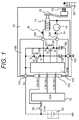
- FIG. 1 is a block diagram of the entire structure of the engine starter according to the embodiment of the present invention.
- An engine starter 10 in FIG. 1 includes a starter control device (STM) 100, a solenoid switch 11, a shift mechanism 12, a pinion 13, and a starter motor 14.
- STM starter control device
- solenoid switch 11 a shift mechanism 12
- pinion 13 a pinion 13
- starter motor 14 a starter motor
- the STM 100 controls the starter motor 14 and the solenoid switch 11.
- the STM 100 includes terminals 101, 102, 103, 104, and 105 as input/output terminals.
- the shift mechanism 12 When the STM 100 turns on the solenoid switch 11, the shift mechanism 12 is moved by a suction force, and the pinion 13 is moved in an arrow direction and is engaged with a ring gear 20 coupled to an engine. In the middle of or after the engagement, the STM 100 actuates the starter motor 14, and the rotation of the starter motor 14 is transmitted to the ring gear 20 via the pinion 13. Then, the engine is started by rotating a crankshaft of the engine 1 and controlling fuel and ignition.
- a battery 50 mounted to a vehicle is connected to an engine control device (engine control module: ECM) 70 via an ignition switch (IGSW) 60.
- ECM engine control module
- IGSW ignition switch
- the ECM 70 performs engine start/stop determination, ignition control, and fuel injection control.
- An input signal of the ECM 70 is an engine rotation signal, an air flow rate signal, and the like.
- An output signal of the ECM 70 is a signal to command the drive of the starter motor 14 (Mo drive signal) and a signal to command the drive of the solenoid switch 11 (So drive signal) via the terminal 104 of the STM 100, and an injection signal and an ignition signal for an injector which is not shown.
- the ECM 70 includes a microcomputer and an input/output interface circuit, and a constant voltage generation circuit which is a power supply for them, and the like which are not shown.
- the battery 50 is connected to the terminal 104 via the IGSW 60, and an on/off signal (IGSW signal) of the IGSW 60 is input to the STM 100.
- the STM 100 is a control module of the starter motor 14 and the solenoid switch 11, and a battery voltage VB is input from the terminal 101.
- the STM 100 is grounded via the terminal 103.
- the So drive signal and the Mo drive signal are input from the ECM 70 to a controller 110 for generating a control signal of the STM 100.
- the controller 110 generates signals to drive a gate terminal G of a semiconductor switch for controlling a current (FET) 150 of the solenoid switch 11 and a gate terminal G of a semiconductor switch for energization (FET) 120 of the starter motor 14 from the above signals and outputs them.
- FET current
- FET energization
- a drain terminal D of the FET 120 is connected to the battery 50 from the terminal 101. Also, a source terminal S is connected to a cathode of a free wheel diode 130 for refluxing the current, and then, is connected to the starter motor 14 via the terminal 102.
- An anode of the free wheel diode 130 is connected to a ground of the starter motor 14 via the terminal 103.
- a drain terminal D of the FET 150 is connected to the battery 50 via the terminal 101. Also, a source terminal S is connected to a cathode of a free wheel diode 160 for refluxing the current, and then, is connected to the solenoid switch 11 via the terminal 105.
- An anode of the free wheel diode 160 is connected to a ground of the solenoid switch 11 via the terminal 103.
- FIG. 2 is a block diagram of the structure of the starter control device (STM) used for the engine starter according to the embodiment of the present invention.
- the STM 100 includes the controller 110.
- the controller 110 includes interface circuits 1102 and 1103 which convert the input signal from outside into an effective voltage signal according to a circuit element to be used, an internal power supply generating circuit 1104 which generates the power supply to a circuit to be used, a motor load determining circuit 1107 which determines whether the starter motor 14 is in an overload state based on an inter-terminal voltage VMo of the starter motor 14, a control signal generating circuit 1106 which generates a command signal to a MOSFET based on the output signal of the motor load determining circuit 1107, gate driving circuits 1109 and 1110 which control on/off of the MOSFET, and a gate power supply generating circuit 1105 which generates a power supply for turning on the MOSFET.
- the interface circuit 1102 outputs an output signal So1 as High when the So drive signal is a command to turn on the FET 150.
- the interface circuit 1103 outputs an output signal Mo1 as High when the Mo drive signal is a command to turn on the FET 120.
- Default settings of the signals So1 and Mo1 are set to be Low.
- the internal power supply generating circuit 1104 When the IGSW signal is input, the internal power supply generating circuit 1104 generates a power supply voltage of 5 V from the battery voltage VB and supplies power supply for operation to circuits included in the gate power supply generating circuit 1105 and the controller 110.
- the gate power supply generating circuit 1105 when the power supply of 5 V is supplied, the gate power supply generating circuit 1105 generates the power supply voltage necessary for driving the gates of the FET 120 and the FET 150 and supplies it to the gate driving circuits 1109 and 1110.
- the control signal generating circuit 1106 which generates the input signal of the gate driving circuit 1110 for driving the FET 120 includes an energization restriction determining circuit 1106A and a comparison circuit 1106B.
- the energization restriction determining circuit 1106A determines an upper limit value of the energization based on the output result of the motor load determining circuit 1107.
- the comparison circuit 1106B outputs a logical add of the output signal Mo1 of the interface circuit 1103 and the output signal E4 of the energization restriction determining circuit 1106A.
- the energization restriction determining circuit 1106A outputs a signal which does not restrict the energization to the comparison circuit 1106B when the output signal E3 of the motor load determining circuit 1107 is Low.
- the energization restriction determining circuit 1106A outputs a signal which restricts the energization to the comparison circuit 1106B when the signal E3 is High.
- the signal which does not restrict the energization is a complete High signal which is a PWM signal of 100% Duty, and the signal which restricts the energization is a PWM signal of 50% Duty.
- the FET 120 does not have the energization restriction when the signal E3 is Low and is driven based on the Mo drive signal.
- the signal E3 is High
- the upper limit value for the energization is set.
- an energization command value Mo1 of the signal Mo1 is larger than the upper limit value
- the energization is restricted to the upper limit value.
- the FET 120 performs on/off operation based on the Mo1 and controls the starter motor 14.
- the set value of the energization restriction at the time when the signal E3 is High is determined based on an allowable value of a load which is applied to the starter motor by reverse rotation of the engine. It is not necessary to set the limit value of the energization to be 50%. The set value may be higher/lower than 50%.
- the set value of the energization restriction at the time when the signal E3 is High is determined based on environmental conditions at the time when the engine starts. It is not necessary to fix the energization limit value to 50%.
- the energization limit value may be variable set value determined according to the environmental conditions at the time when the engine starts.
- the limit value may be set to be variable based on the temperature detection result obtained by newly providing a temperature detecting unit in the controller 110.
- the limit value may be set to be variable according to an engine state by connecting the controller 110 to the ECM 70 via a serial communication function.
- a PWM control frequency of the FET 120 when the energization is restricted is determined based on a time constant of the starter motor 14. It is not necessary for the PWM control frequency to be a fixed frequency.
- the PWM control frequency may be a variable set value determined based on the inter-terminal voltage VMo of the starter motor 14.
- the motor load determining circuit 1107 which outputs the load state determination result of the starter motor 14 to the control signal generating circuit 1106 includes a comparison circuit 1107A which outputs comparison result (signal E1) of the inputs including the inter-terminal voltage VMo of the starter motor 14 and the reference voltage VREF, an AND circuit 1107B which outputs logical add calculation result (signal E2) of the inputs including the signal E1 and the output signal Mo1 of the interface circuit 1103, and a counter circuit 1107C which counts a state of the signal E2.
- the comparison circuit 1107A outputs the signal E1 as High when the inter-terminal voltage VMo of the starter motor 14 is lower than the reference voltage VREF.
- the motor load determining circuit 1107 determines whether the starter motor 14 is in the overload state by directly monitoring the inter-terminal voltage VMo of the starter motor 14.
- the motor load determining circuit 1107 is configured not to wrongly determine the overload state of the starter motor 14 based on the inter-terminal voltage VMo immediately after the energization to the starter motor 14 and before the generation of an induced voltage in the starter motor.
- the motor load determining circuit 1107 resets the signal E3 from High to Low and energizes the FET 120 based on the Mo drive signal.
- the gate driving circuit 1109 for driving the FET 150 turns on the FET 150.
- the So drive signal and the Mo drive signal are on/off binary signals.
- PWM signals may be used as the So drive signal and the Mo drive signal.
- the counter circuit 1107C counts a High state of the signal E2 and determines the overload state based on the number of counts in the predetermined time.
- the use of the PWM signal is realized by generating a limit signal as the PWM signal having the frequency synchronized with the Mo drive signal.
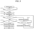
- FIG. 3 is a flowchart of an operation of the engine starter according to the embodiment of the present invention.
- FIG. 3 a case below is described.
- a driver has already turned on the IGSW 60, the ECM 70 has started, and the engine has been stably rotated. After that, a condition for requesting idling stop is satisfied so that the engine starts to decelerate by inertial rotation by stopping the fuel supply to the engine. After that, when the engine reaches a range near zero rotation, the engine is restarted by a request of the driver to restart.
- step 101 the driver indicates the intension to restart by releasing a brake pedal.
- the procedure proceeds to step 102.
- the FET 150 is turned on based on a solenoid drive signal from the ECM 70, and the solenoid is energized. Then, the pinion 13 is moved by the shift mechanism 12 in the arrow direction and is engaged with the ring gear 20.
- step 103 the procedure proceeds to step 103.
- the FET 120 is turned on based on a starter motor drive signal from the ECM 70, and the starter motor 14 is energized so that the pinion starts to rotate forward. Then, the pinion engages with the ring gear, and this makes the engine crank.
- step 104 when it is determined that the starter motor 14 is not in the overload state, the starter motor 14 is energized based on the starter motor drive signal from the ECM 70 and continues the cranking.
- step 105 When the rotation of the engine reaches a predetermined number of rotations and the engine is completely combusted, the procedure proceeds to steps 106 and 107. The energization commands to the starter motor and the solenoid are canceled, and engine start processing is completed.
- step 104 the engine start operation in a case where the overload state is detected in step 104 is described.
- the processing in which the driver indicates the intension to restart by releasing the brake pedal and condition for requesting to restart the engine is satisfied and it is determined that the request for restarting the engine is generated to the processing in step 103 are the same as those of the normal operation.
- step 105 when the starter motor 14 tries to rotate forward based on the starter motor drive signal in a state where the engine is reversely rotated with some cause, the inter-terminal voltage VMo of the starter motor 14 is decreased. After that, a state where the inter-terminal voltage VMo is equal to or lower than a threshold VREF is continued for a predetermined time, the motor load determining circuit 1107 determines that it is the overload state. The procedure proceeds to step 201, and the energization to the starter motor 14 is restricted by the control signal generating circuit 1106.
- the energization to the starter motor is restricted.
- the energization to the solenoid is continued based on the command of the ECM 70.
- step 202 An energization restriction operation time is monitored, and the energization restriction is continued until the energization restriction operation time reaches a predetermined time.
- step 202 when it is determined that the energization restriction operation is continued for a predetermined time, the procedure proceeds to step 203.
- the energization restriction to the starter motor is canceled, and the procedure returns to step 104.
- step 104 when it is determined that the starter motor is in the overload state again, the procedure proceeds to step 201.
- the procedure proceeds to step 2011.
- the starter motor is energized based on the command of the ECM 70 until the engine is completely combusted, and the starter motor 14 starts to rotate, and the engine cranks, and the start of the engine is completed.
- an engine start control device can prevent the flow of an excessive load current in the starter motor while preventing a damage of a starter motor drive force transmission mechanism by preventing generation of an excessive load to damage the starter motor drive force transmission mechanism provided between the starter motor and the engine. While preventing decrease in the battery voltage caused by the excessive load current, the engine can be restarted without impairing engine starting performance.
- the starter motor repeats the energization restriction and the energization based on the Mo drive signal at a predetermined interval in the overload state so that the cranking of the engine is available at the timing when the overload to the starter motor is reduced, and the engine can be quickly restarted.
- FIGs. 4 and 5 are another embodiment of the present invention.
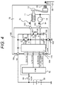
- FIG. 4 is a block diagram of an entire structure of an engine starter
- FIG. 5 is a block diagram of a structure of a starter control device (STM).
- STM starter control device
- control signal generating circuit 1106 provided in the controller 110 determines an energization restriction value based on the output signal E3 of the motor load determining circuit 1107 and outputs it to the gate driving circuit 1110. Therefore, energization control of the starter motor 14 according to the environment conditions of the engine is not easy.
- the motor load determining circuit 1107 determines that the starter motor 14 is in the overload state, and the energization to the starter motor 14 is restricted. Accordingly, the starter motor 14 cannot crank the engine so as to reach the number of rotations of the engine necessary for the complete combustion of the engine, and there is a possibility that the engine cannot be started.
- a motor inter-terminal voltage VMo is fed back to an ECM 70 via a terminal 104, and a microcomputer (which is not shown) provided in the ECM 70 calculates an optimal energization signal of the starter motor 14 based on environmental conditions at the time of engine start, an in-vehicle LAN signal, and a voltage signal between motor terminals and outputs a Mo drive signal to the terminal 104.
- the voltage signal between motor terminals is the motor inter-terminal voltage VMo output to the terminal 104 via an interface circuit 1105.
- the engine can be started by the optimal energization control of the starter motor according to the environmental conditions at the time of the engine start, and the engine can be started so as not to cause the overload of the starter motor in a case where the engine is restarted after idling stop is allowed.
- control circuit 110 since it is not necessary to provide the control signal generating circuit 1106 and the motor load determining circuit 1107 provided in the controller 110, a control circuit 110 can be inexpensively realized.
- FIGs. 6 and 7 are still another embodiment of the present invention.
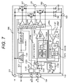
- FIG. 6 is a block diagram of an entire structure of an engine starter
- FIG. 7 is a block diagram of a structure of a starter control device (STM).
- STM starter control device
- an engine starter 10 includes a FET 170 which is turned on/off according to a command from a controller 110, a magnetic switch 15 for energizing from a terminal 101 to a starter motor 14 when the FET 170 is turned on, a free wheel diode 180 which is connected between the terminal S of the FET 170 and the terminal 103, and a cathode of the free wheel diode 180 is connected to the terminal S of the FET 170 and a single terminal of a solenoid coil of the magnetic switch 15.
- the controller 110 includes a start scene determination circuit 1120 which determines whether the start is a first start based on an IGSW signal and a Mo drive signal and a gate driving circuit 111 which drives the FET 170.
- the Mo drive signal is output to the gate driving circuit 1111, and the starter motor 14 is energized via the magnetic switch 15 and rotates the engine.
- the Mo drive signal is output to the gate driving circuit 1110 via the gate driving circuit control signal generating circuit 1106, and the starter motor 14 is energized via the FET 120 and rotates the engine.
- the starter motor 14 when the engine is sometimes started by flowing a large current to the starter motor 14 in a case where the engine is started at the time when the engine is cooled and when the engine is started at the first time without having no possibility that an excessive load caused by reverse rotation of the engine is generated, the starter motor 14 is energized via the magnetic switch 15. Therefore, since a current capacity of the FET 120 can be set based on a motor current necessary for restarting the engine, the controller 110 can be inexpensively realized.
- two lines of energization paths to the starter motor 14 are independently provided which are used at the time of the first start and at the time of restart. Accordingly, the life of the FET 120 can be improved.
- the engine can be surely started at the first time.
- FIGs. 8 and 9 are yet another embodiment of the present invention.
- FIG. 8 is a block diagram of an entire structure of an engine starter
- FIG. 9 is a block diagram of a structure of a starter control device (STM).
- STM starter control device
- the control signal of the engine starter 10 includes two signals, i.e., the Mo drive signal and the So drive signal.
- the control signal is configured of an ST drive signal which includes both a signal for driving a solenoid 11 and a signal for driving the starter motor 14.
- the controller 110 outputs the ST drive signal via an interface circuit 1102 as an ST1 signal and an ST2 signal.
- the ST1 signal is input to the gate driving circuit 1109, and the ST2 signal is input to a control signal generating circuit 1106 and a motor load determining circuit 1107.
- the control signal from the ECM 70 is a single signal, the controller 110 functions similarly to the first embodiment.
- the ST drive signal may be a data communication signal corresponding to a serial communication function including information of a setting value such as a PWM limit signal and a VREF provided in the controller 110.
- the ST drive signal may be the data communication signal including information indicating the state of the engine starter 10 such as a voltage signal between motor terminals.
- the communication between the ECM 70 and the engine starter 10 is performed by using a single signal line, and the engine can be started without causing overload to the starter motor when the engine is restarted after idling stop is allowed.
- the wiring cost of the ECM 70 and the engine starter 10 can be reduced, and a possibility of a failure caused by a signal line can be reduced, and a malfunction of the engine starter can be prevented.
- the engine start control device prevents the generation of the excessive load to damage the starter motor drive force transmission mechanism provided between the starter motor and the engine. Accordingly, while the damage of the starter motor drive force transmission mechanism is prevented, the flow of the excessive load current in the starter motor can be prevented. Therefore, the engine can be restarted without impairing the engine starting performance while preventing the decrease in the battery voltage caused by the excessive load current.
- the decrease in the battery voltage caused by the excessive load can be prevented by preventing the excessive load to the starter motor, and the engine restart response to the restart request of the driver can be faster.
- the present invention is not limited to the embodiments and includes various modifications.
- the embodiments have been described in detail for easy understanding of the present invention.
- the embodiments are not limited to those including all the components described above.
- a part of the components of the embodiment can be replaced with that of the other embodiment, and the components of the embodiment can be added to the other embodiment.
- a part of the components of each embodiment can be deleted, replaced with that of the other embodiment, and a part of the other embodiment can be added to the components of the embodiment.
Abstract
Description
- The present invention relates to an engine starter to start an engine of a vehicle.
- In recent years, to save fuel consumption and preserve the environment, an idling stop function such that fuel supply to an engine is stopped and rotation of the engine is temporarily stopped when a vehicle temporality stops to wait for the light to change and the like is employed in some vehicles.
- Also, before the vehicle is stopped or during inertia traveling in a decelerating condition in which an accelerator pedal is released during cruising travel, the idling stop is actively performed so that a region where the fuel supply to the engine is stopped is enlarged, and fuel consumption saving effect can be further enhanced.
- When the idling stop is allowed, the fuel supply stop causes the engine to start the inertial rotation. After that, the engine goes through a swing-back state in which the engine repeats forward rotation and reverse rotation in a range near zero rotation, and the engine is completely stopped. When a request to restart is received in the swing-back period, it is necessary to quickly restart the engine to ensure vehicle starting performance. However, when the starter motor is rotated according to the engine restart request in a state where the engine is reversely rotated or is likely to be reversely rotated with some cause, the starter motor tries to make the engine, which is reversely rotated, rotate forward. Therefore, an excessive load is applied to the starter motor, and there is a possibility to damage a drive force transmission mechanism for transmitting a drive force of the starter motor to the engine.
- A technique has been proposed in which a reverse rotation detecting unit for detecting whether the engine is reversely rotated is provided so as not to generate the excessive load to the starter motor when the starter motor is energized and the rotation of the starter motor is prohibited when the reverse rotation of the engine is detected. (refer to PTL 1) According to Patent Literature 1, when the reverse rotation of the engine is detected, the starter motor is not rotated. Therefore, the excessive load is not applied to the starter motor, and damage of the starter motor can be prevented.
- PTL 1:
JP 4096863 B1 - In the technique disclosed in PTL 1, the reverse rotation of the engine is detected by detecting a rotation direction of a crankshaft in one cylinder in the engine, and the rotation of the starter motor is prohibited when the reverse rotation is detected. Also, whether the engine is reversely rotated is predicted by detecting a compressed state of gas in the one cylinder in the engine, and the rotation of the starter motor in a period when the reverse rotation of the engine is predicted is prohibited.
- That is, according to the technique disclosed in PTL 1, in the period when the engine is reversely rotated or when the reverse rotation of the engine is predicted, the start of the engine by the starter motor is prohibited.
- As a result, in a case where the engine is restarted due to change-of-mind, since the engine is restarted by driving the starter motor after the reverse rotation is completely stopped, a response delay of several hundred milliseconds at the maximum is gene rated from the time when the driver requests to restart the engine, and the driver may feel uncomfortable.
- A purpose of the present invention is to provide an engine start control device which can solve the above problems.
- To solve the problem, for example, a structure according to claims is employed. The present application includes a plurality of solutions to solve the problems. An example is an engine starter including a pinion which is engaged with a ring gear coupled to an engine, a solenoid switch which moves the pinion to the side of the ring gear by using a current supplied from a battery, a starter motor which rotates the pinion by using the current, and a starter controller which supplies necessary current to the starter motor and the solenoid switch based on a signal from a control device for instructing to start the engine. The starter controller includes a starter motor load determining unit which determines a load state of the starter motor based on a terminal voltage of the starter motor when the starter motor is rotated according to the signal.
- According to the present invention, an engine starter can be provided which can restart an engine without impairing engine starting performance while preventing a flow of an excessive load current to a starter motor. A problem, a structure, and an effect other than the above are described in the embodiments below.
-
- [
FIG. 1] FIG. 1 is an exemplary block diagram of an entire structure of an engine starter according to an embodiment of the present invention. - [
FIG. 2] FIG. 2 is an exemplary block diagram of a structure of a starter control device (STM) used for the engine starter according to the embodiment of the present invention. - [
FIG. 3] FIG. 3 is an exemplary flowchart of an operation of the engine starter according to the embodiment of the present invention at the time of a normal operation and at the time of an overload operation. - [
FIG. 4] FIG. 4 is an exemplary block diagram of an entire structure of an engine starter according to another form of the embodiment. - [
FIG. 5] FIG. 5 is an exemplary block diagram of a structure of a starter control device (STM) used for the engine starter according to another form of the embodiment. - [
FIG. 6] FIG. 6 is an exemplary block diagram of an entire structure of an engine starter according to still another form of the embodiment. - [
FIG. 7] FIG. 7 is an exemplary block diagram of a structure of a starter control device (STM) used for the engine starter according to still another form of the embodiment. - [
FIG. 8] FIG. 8 is an exemplary block diagram of an entire structure of an engine starter according to yet another form of the embodiment. - [
FIG. 9] FIG. 9 is an exemplary block diagram of a structure of a starter control device (STM) used for the engine starter according to yet another form of the embodiment. - Embodiments of the present invention are described below with reference to the drawings.
- A structure and an operation of an engine starter according to a first embodiment of the present invention is described with reference to
FIGs. 1 to 3 . - First, an entire structure of the engine starter according to the present embodiment is described with reference to
FIG. 1 . -
FIG. 1 is a block diagram of the entire structure of the engine starter according to the embodiment of the present invention. - An
engine starter 10 inFIG. 1 includes a starter control device (STM) 100, asolenoid switch 11, ashift mechanism 12, apinion 13, and astarter motor 14. - The STM 100 controls the
starter motor 14 and thesolenoid switch 11. The STM 100 includesterminals - When the
STM 100 turns on thesolenoid switch 11, theshift mechanism 12 is moved by a suction force, and thepinion 13 is moved in an arrow direction and is engaged with aring gear 20 coupled to an engine. In the middle of or after the engagement, the STM 100 actuates thestarter motor 14, and the rotation of thestarter motor 14 is transmitted to thering gear 20 via thepinion 13. Then, the engine is started by rotating a crankshaft of the engine 1 and controlling fuel and ignition. - A
battery 50 mounted to a vehicle is connected to an engine control device (engine control module: ECM) 70 via an ignition switch (IGSW) 60. - The ECM 70 performs engine start/stop determination, ignition control, and fuel injection control. An input signal of the
ECM 70 is an engine rotation signal, an air flow rate signal, and the like. An output signal of theECM 70 is a signal to command the drive of the starter motor 14 (Mo drive signal) and a signal to command the drive of the solenoid switch 11 (So drive signal) via theterminal 104 of theSTM 100, and an injection signal and an ignition signal for an injector which is not shown. The ECM 70 includes a microcomputer and an input/output interface circuit, and a constant voltage generation circuit which is a power supply for them, and the like which are not shown. In addition, thebattery 50 is connected to theterminal 104 via the IGSW 60, and an on/off signal (IGSW signal) of the IGSW 60 is input to theSTM 100. - The
STM 100 is a control module of thestarter motor 14 and thesolenoid switch 11, and a battery voltage VB is input from theterminal 101. The STM 100 is grounded via theterminal 103. - The So drive signal and the Mo drive signal are input from the
ECM 70 to acontroller 110 for generating a control signal of theSTM 100. Thecontroller 110 generates signals to drive a gate terminal G of a semiconductor switch for controlling a current (FET) 150 of thesolenoid switch 11 and a gate terminal G of a semiconductor switch for energization (FET) 120 of thestarter motor 14 from the above signals and outputs them. - A drain terminal D of the FET 120 is connected to the
battery 50 from theterminal 101. Also, a source terminal S is connected to a cathode of afree wheel diode 130 for refluxing the current, and then, is connected to thestarter motor 14 via theterminal 102. - An anode of the
free wheel diode 130 is connected to a ground of thestarter motor 14 via theterminal 103. - A drain terminal D of the FET 150 is connected to the
battery 50 via theterminal 101. Also, a source terminal S is connected to a cathode of afree wheel diode 160 for refluxing the current, and then, is connected to thesolenoid switch 11 via theterminal 105. - An anode of the
free wheel diode 160 is connected to a ground of thesolenoid switch 11 via theterminal 103. - Next, a structure of the starter control device (STM) 100 used for the engine starter according to the present embodiment is described with reference to
FIG. 2. FIG. 2 is a block diagram of the structure of the starter control device (STM) used for the engine starter according to the embodiment of the present invention. - The
STM 100 includes thecontroller 110. Thecontroller 110 includesinterface circuits supply generating circuit 1104 which generates the power supply to a circuit to be used, a motorload determining circuit 1107 which determines whether thestarter motor 14 is in an overload state based on an inter-terminal voltage VMo of thestarter motor 14, a controlsignal generating circuit 1106 which generates a command signal to a MOSFET based on the output signal of the motorload determining circuit 1107,gate driving circuits supply generating circuit 1105 which generates a power supply for turning on the MOSFET. - The
interface circuit 1102 outputs an output signal So1 as High when the So drive signal is a command to turn on theFET 150. - Also, the
interface circuit 1103 outputs an output signal Mo1 as High when the Mo drive signal is a command to turn on theFET 120. - Default settings of the signals So1 and Mo1 are set to be Low.
- When the IGSW signal is input, the internal power
supply generating circuit 1104 generates a power supply voltage of 5 V from the battery voltage VB and supplies power supply for operation to circuits included in the gate powersupply generating circuit 1105 and thecontroller 110. - Also, when the power supply of 5 V is supplied, the gate power
supply generating circuit 1105 generates the power supply voltage necessary for driving the gates of theFET 120 and theFET 150 and supplies it to thegate driving circuits - The control
signal generating circuit 1106 which generates the input signal of thegate driving circuit 1110 for driving theFET 120 includes an energizationrestriction determining circuit 1106A and acomparison circuit 1106B. The energizationrestriction determining circuit 1106A determines an upper limit value of the energization based on the output result of the motorload determining circuit 1107. Thecomparison circuit 1106B outputs a logical add of the output signal Mo1 of theinterface circuit 1103 and the output signal E4 of the energizationrestriction determining circuit 1106A. - The energization
restriction determining circuit 1106A outputs a signal which does not restrict the energization to thecomparison circuit 1106B when the output signal E3 of the motorload determining circuit 1107 is Low. The energizationrestriction determining circuit 1106A outputs a signal which restricts the energization to thecomparison circuit 1106B when the signal E3 is High. The signal which does not restrict the energization is a complete High signal which is a PWM signal of 100% Duty, and the signal which restricts the energization is a PWM signal of 50% Duty. - That is, the
FET 120 does not have the energization restriction when the signal E3 is Low and is driven based on the Mo drive signal. When the signal E3 is High, the upper limit value for the energization is set. When an energization command value Mo1 of the signal Mo1 is larger than the upper limit value, the energization is restricted to the upper limit value. When the energization command value Mo1 is smaller than the upper limit value, theFET 120 performs on/off operation based on the Mo1 and controls thestarter motor 14. - The set value of the energization restriction at the time when the signal E3 is High is determined based on an allowable value of a load which is applied to the starter motor by reverse rotation of the engine. It is not necessary to set the limit value of the energization to be 50%. The set value may be higher/lower than 50%.
- In addition, the set value of the energization restriction at the time when the signal E3 is High is determined based on environmental conditions at the time when the engine starts. It is not necessary to fix the energization limit value to 50%. The energization limit value may be variable set value determined according to the environmental conditions at the time when the engine starts. When the energization limit value is variable, the limit value may be set to be variable based on the temperature detection result obtained by newly providing a temperature detecting unit in the
controller 110. Also, the limit value may be set to be variable according to an engine state by connecting thecontroller 110 to theECM 70 via a serial communication function. - In addition, a PWM control frequency of the
FET 120 when the energization is restricted is determined based on a time constant of thestarter motor 14. It is not necessary for the PWM control frequency to be a fixed frequency. The PWM control frequency may be a variable set value determined based on the inter-terminal voltage VMo of thestarter motor 14. - The motor
load determining circuit 1107 which outputs the load state determination result of thestarter motor 14 to the controlsignal generating circuit 1106 includes acomparison circuit 1107A which outputs comparison result (signal E1) of the inputs including the inter-terminal voltage VMo of thestarter motor 14 and the reference voltage VREF, an ANDcircuit 1107B which outputs logical add calculation result (signal E2) of the inputs including the signal E1 and the output signal Mo1 of theinterface circuit 1103, and acounter circuit 1107C which counts a state of the signal E2. - The
comparison circuit 1107A outputs the signal E1 as High when the inter-terminal voltage VMo of thestarter motor 14 is lower than the reference voltage VREF. The ANDcircuit 1107B outputs the signal E2 as High when the signal Mo1 is High and the signal E1 is High. After that, a state of signal E2 = High is continued for a predetermined time, thecounter circuit 1107C outputs the signal E3 as High. Default settings of the signal E1, E2, and E3 are Low. - That is, when the Mo drive signal is a command for turning on the
FET 120 and rotating thestarter motor 14, the motorload determining circuit 1107 determines whether thestarter motor 14 is in the overload state by directly monitoring the inter-terminal voltage VMo of thestarter motor 14. - In addition, by providing the
counter circuit 1107C, the motorload determining circuit 1107 is configured not to wrongly determine the overload state of thestarter motor 14 based on the inter-terminal voltage VMo immediately after the energization to thestarter motor 14 and before the generation of an induced voltage in the starter motor. - In addition, when the
counter circuit 1107C has output the signal E3 as High and a predetermined time has elapsed after that, the motorload determining circuit 1107 resets the signal E3 from High to Low and energizes theFET 120 based on the Mo drive signal. - When the output signal So1 of the
interface circuit 1102 is directly input to thegate driving circuit 1109 and the signal So1 is High, thegate driving circuit 1109 for driving theFET 150 turns on theFET 150. - That is, even when it is determined that the
starter motor 14 is in the overload state and the energization of theFET 120 is restricted, the energization of theFET 150 is maintained not to be restricted and thepinion 13 is stably engaged with the ring gear. - In the above description, the So drive signal and the Mo drive signal are on/off binary signals. However, PWM signals may be used as the So drive signal and the Mo drive signal.
- In this case, since the output signal E2 of the AND
circuit 1107B is generated as the PWM signal, thecounter circuit 1107C counts a High state of the signal E2 and determines the overload state based on the number of counts in the predetermined time. - In addition, the use of the PWM signal is realized by generating a limit signal as the PWM signal having the frequency synchronized with the Mo drive signal.
- Next, a normal engine start operation and an engine start operation in a case where the overload state occurs of the engine starter according to the present embodiment are described with reference to
FIG. 3. FIG. 3 is a flowchart of an operation of the engine starter according to the embodiment of the present invention. - The normal engine start operation is described first.
- In
FIG. 3 , a case below is described. A driver has already turned on theIGSW 60, theECM 70 has started, and the engine has been stably rotated. After that, a condition for requesting idling stop is satisfied so that the engine starts to decelerate by inertial rotation by stopping the fuel supply to the engine. After that, when the engine reaches a range near zero rotation, the engine is restarted by a request of the driver to restart. - In
step 101, the driver indicates the intension to restart by releasing a brake pedal. When the condition for requesting to restart the engine is satisfied and it is determined that the request for restarting the engine is generated, the procedure proceeds to step 102. TheFET 150 is turned on based on a solenoid drive signal from theECM 70, and the solenoid is energized. Then, thepinion 13 is moved by theshift mechanism 12 in the arrow direction and is engaged with thering gear 20. - After that, the procedure proceeds to step 103. When a predetermined time elapses, the
FET 120 is turned on based on a starter motor drive signal from theECM 70, and thestarter motor 14 is energized so that the pinion starts to rotate forward. Then, the pinion engages with the ring gear, and this makes the engine crank. - In
step 104, when it is determined that thestarter motor 14 is not in the overload state, thestarter motor 14 is energized based on the starter motor drive signal from theECM 70 and continues the cranking. - After that, the procedure proceeds to step 105. When the rotation of the engine reaches a predetermined number of rotations and the engine is completely combusted, the procedure proceeds to
steps - Next, the engine start operation in a case where the overload state is detected in
step 104 is described. - The processing in which the driver indicates the intension to restart by releasing the brake pedal and condition for requesting to restart the engine is satisfied and it is determined that the request for restarting the engine is generated to the processing in
step 103 are the same as those of the normal operation. - In
step 105, when thestarter motor 14 tries to rotate forward based on the starter motor drive signal in a state where the engine is reversely rotated with some cause, the inter-terminal voltage VMo of thestarter motor 14 is decreased. After that, a state where the inter-terminal voltage VMo is equal to or lower than a threshold VREF is continued for a predetermined time, the motorload determining circuit 1107 determines that it is the overload state. The procedure proceeds to step 201, and the energization to thestarter motor 14 is restricted by the controlsignal generating circuit 1106. - In this case, the energization to the starter motor is restricted. However, the energization to the solenoid is continued based on the command of the
ECM 70. - When the energization restriction to the starter motor is started, the procedure proceeds to step 202. An energization restriction operation time is monitored, and the energization restriction is continued until the energization restriction operation time reaches a predetermined time.
- In
step 202, when it is determined that the energization restriction operation is continued for a predetermined time, the procedure proceeds to step 203. The energization restriction to the starter motor is canceled, and the procedure returns to step 104. - In
step 104, when it is determined that the starter motor is in the overload state again, the procedure proceeds to step 201. When it is determined that the starter motor is not in the overload state, the procedure proceeds to step 2011. The starter motor is energized based on the command of theECM 70 until the engine is completely combusted, and thestarter motor 14 starts to rotate, and the engine cranks, and the start of the engine is completed. - As described above, according to the present invention, even when the starter motor is rotated by the request to restart in a state where the engine is reversely rotated or reverse rotation of the engine is predicted, an engine start control device can prevent the flow of an excessive load current in the starter motor while preventing a damage of a starter motor drive force transmission mechanism by preventing generation of an excessive load to damage the starter motor drive force transmission mechanism provided between the starter motor and the engine. While preventing decrease in the battery voltage caused by the excessive load current, the engine can be restarted without impairing engine starting performance.
- In addition, the starter motor repeats the energization restriction and the energization based on the Mo drive signal at a predetermined interval in the overload state so that the cranking of the engine is available at the timing when the overload to the starter motor is reduced, and the engine can be quickly restarted.
-
FIGs. 4 and5 are another embodiment of the present invention. -
FIG. 4 is a block diagram of an entire structure of an engine starter, andFIG. 5 is a block diagram of a structure of a starter control device (STM). The components and signals which are the same as those inFIGs. 1 and2 are denoted with the same reference numerals. - In the first embodiment, the control
signal generating circuit 1106 provided in thecontroller 110 determines an energization restriction value based on the output signal E3 of the motorload determining circuit 1107 and outputs it to thegate driving circuit 1110. Therefore, energization control of thestarter motor 14 according to the environment conditions of the engine is not easy. - When the engine is started first, and especially, when the engine is started first at very low temperature by using the maximum torque characteristics of the
starter motor 14 to the maximum extent, the motorload determining circuit 1107 determines that thestarter motor 14 is in the overload state, and the energization to thestarter motor 14 is restricted. Accordingly, thestarter motor 14 cannot crank the engine so as to reach the number of rotations of the engine necessary for the complete combustion of the engine, and there is a possibility that the engine cannot be started. - In the second embodiment, as illustrated in
FIG. 4 , a motor inter-terminal voltage VMo is fed back to anECM 70 via a terminal 104, and a microcomputer (which is not shown) provided in theECM 70 calculates an optimal energization signal of thestarter motor 14 based on environmental conditions at the time of engine start, an in-vehicle LAN signal, and a voltage signal between motor terminals and outputs a Mo drive signal to the terminal 104. - As illustrated in
FIG. 5 , the voltage signal between motor terminals is the motor inter-terminal voltage VMo output to the terminal 104 via aninterface circuit 1105. - As described above, according to the second embodiment, the engine can be started by the optimal energization control of the starter motor according to the environmental conditions at the time of the engine start, and the engine can be started so as not to cause the overload of the starter motor in a case where the engine is restarted after idling stop is allowed.
- In addition, since it is not necessary to provide the control
signal generating circuit 1106 and the motorload determining circuit 1107 provided in thecontroller 110, acontrol circuit 110 can be inexpensively realized. -
FIGs. 6 and7 are still another embodiment of the present invention. -
FIG. 6 is a block diagram of an entire structure of an engine starter, andFIG. 7 is a block diagram of a structure of a starter control device (STM). The components and signals which are the same as those inFIGs. 1 and2 are denoted with the same reference numerals. - As illustrated in
FIG. 6 , in addition to the components inFIG. 1 , anengine starter 10 includes aFET 170 which is turned on/off according to a command from acontroller 110, amagnetic switch 15 for energizing from a terminal 101 to astarter motor 14 when theFET 170 is turned on, afree wheel diode 180 which is connected between the terminal S of theFET 170 and the terminal 103, and a cathode of thefree wheel diode 180 is connected to the terminal S of theFET 170 and a single terminal of a solenoid coil of themagnetic switch 15. - Also, as illustrated in
FIG. 7 , in addition toFIG. 2 , thecontroller 110 includes a startscene determination circuit 1120 which determines whether the start is a first start based on an IGSW signal and a Mo drive signal and a gate driving circuit 111 which drives theFET 170. - When the start
scene determination circuit 1120 has determined that the start is the first start scene, the Mo drive signal is output to the gate driving circuit 1111, and thestarter motor 14 is energized via themagnetic switch 15 and rotates the engine. - Also, when the start
scene determination circuit 1120 has determined that the start is the restart scene after idling stop is allowed, the Mo drive signal is output to thegate driving circuit 1110 via the gate driving circuit controlsignal generating circuit 1106, and thestarter motor 14 is energized via theFET 120 and rotates the engine. - As described above, according to the third embodiment, when the engine is sometimes started by flowing a large current to the
starter motor 14 in a case where the engine is started at the time when the engine is cooled and when the engine is started at the first time without having no possibility that an excessive load caused by reverse rotation of the engine is generated, thestarter motor 14 is energized via themagnetic switch 15. Therefore, since a current capacity of theFET 120 can be set based on a motor current necessary for restarting the engine, thecontroller 110 can be inexpensively realized. - In addition, two lines of energization paths to the
starter motor 14 are independently provided which are used at the time of the first start and at the time of restart. Accordingly, the life of theFET 120 can be improved. - In addition, even when a failure occurs in the
FET 120, the engine can be surely started at the first time. -
FIGs. 8 and9 are yet another embodiment of the present invention. -
FIG. 8 is a block diagram of an entire structure of an engine starter, andFIG. 9 is a block diagram of a structure of a starter control device (STM). The components and signals which are the same as those inFIGs. 1 and2 are denoted with the same reference numerals. - In
FIG. 1 , the control signal of theengine starter 10 includes two signals, i.e., the Mo drive signal and the So drive signal. However, as illustrated inFIG. 8 , the control signal is configured of an ST drive signal which includes both a signal for driving asolenoid 11 and a signal for driving thestarter motor 14. - Also, the
controller 110 outputs the ST drive signal via aninterface circuit 1102 as an ST1 signal and an ST2 signal. The ST1 signal is input to thegate driving circuit 1109, and the ST2 signal is input to a controlsignal generating circuit 1106 and a motorload determining circuit 1107. Although the control signal from theECM 70 is a single signal, thecontroller 110 functions similarly to the first embodiment. - The ST drive signal may be a data communication signal corresponding to a serial communication function including information of a setting value such as a PWM limit signal and a VREF provided in the
controller 110. - In addition, the ST drive signal may be the data communication signal including information indicating the state of the
engine starter 10 such as a voltage signal between motor terminals. - As described above, according to the fourth embodiment, the communication between the
ECM 70 and theengine starter 10 is performed by using a single signal line, and the engine can be started without causing overload to the starter motor when the engine is restarted after idling stop is allowed. - Also, by using the single signal line, the wiring cost of the
ECM 70 and theengine starter 10 can be reduced, and a possibility of a failure caused by a signal line can be reduced, and a malfunction of the engine starter can be prevented. As described above, even when the starter motor is rotated by the restart request in a state where the reverse rotation of the engine is predicted or is performed, the engine start control device according to the present invention prevents the generation of the excessive load to damage the starter motor drive force transmission mechanism provided between the starter motor and the engine. Accordingly, while the damage of the starter motor drive force transmission mechanism is prevented, the flow of the excessive load current in the starter motor can be prevented. Therefore, the engine can be restarted without impairing the engine starting performance while preventing the decrease in the battery voltage caused by the excessive load current. In other words, according to the present invention, when the engine is restarted in a scene of change-of-mind, the decrease in the battery voltage caused by the excessive load can be prevented by preventing the excessive load to the starter motor, and the engine restart response to the restart request of the driver can be faster. - The present invention is not limited to the embodiments and includes various modifications. For example, the embodiments have been described in detail for easy understanding of the present invention. The embodiments are not limited to those including all the components described above. Also, a part of the components of the embodiment can be replaced with that of the other embodiment, and the components of the embodiment can be added to the other embodiment. Also, a part of the components of each embodiment can be deleted, replaced with that of the other embodiment, and a part of the other embodiment can be added to the components of the embodiment.
-
- 10 engine start control device
- 11 solenoid switch
- 12 shift mechanism
- 13 pinion
- 14 starter motor
- 20 ring gear
- 50 battery
- 60 ignition switch (IG-SW)
- 70 engine control device (ECM)
- 80 relay
- 100 starter control device (STM)
- 110 pre-driver
- 120, 150 semiconductor switch (FET)
- 130, 160 flywheel diode
- B, S, M, 101, 102, 103, 104 connection terminal of engine starter
Claims (6)
- An engine starter comprising:a pinion configured to be engaged with a ring gear coupled to an engine;a solenoid switch configured to move the pinion to a side of the ring gear by using a current supplied from a battery;a starter motor configured to rotate the pinion by using the current; anda starter controller configured to supply a necessary current to the starter motor and the solenoid switch based on a signal from a control device for instructing the engine to start, whereinthe starter controller includes a starter motor load determining unit which determines a load state of the starter motor based on a terminal voltage of the starter motor when the starter motor is rotated according to the signal.
- The engine starter according to claim 1, wherein
the starter motor load determining unit determines that the starter motor is in an overload state when an inter-terminal voltage of the starter motor reaches a predetermined state relative to a reference voltage. - The engine starter according to claim 1 or 2, wherein
when the starter motor load determining unit has determined that the starter motor is in the overload state, energization from the starter controller to the starter motor is restricted. - The engine starter according to claim 3, wherein
when the energization restriction has been performed for a predetermined time, the energization restriction is canceled, and a test current is flown to the starter motor based on the command, and
when it is determined that the starter motor is in the overload state, the energization to the starter motor is restricted again. - The engine starter according to claim 3, wherein
the solenoid switch is energized by using a second power supply line different from a power supply line to the starter motor so as not to restrict the energization to the solenoid switch when the energization to the starter motor is restricted. - The engine starter according to claim 5, wherein
the second power supply line is connected to an input terminal of the solenoid switch via a switch unit, and a semiconductor element is used for the switch unit.
Applications Claiming Priority (2)
| Application Number | Priority Date | Filing Date | Title |
|---|---|---|---|
| JP2014000703 | 2014-01-07 | ||
| PCT/JP2014/081132 WO2015104910A1 (en) | 2014-01-07 | 2014-11-26 | Engine starting device |
Publications (3)
| Publication Number | Publication Date |
|---|---|
| EP3093483A1 true EP3093483A1 (en) | 2016-11-16 |
| EP3093483A4 EP3093483A4 (en) | 2018-06-13 |
| EP3093483B1 EP3093483B1 (en) | 2024-05-01 |
Family
ID=53523750
Family Applications (1)
| Application Number | Title | Priority Date | Filing Date |
|---|---|---|---|
| EP14878047.1A Active EP3093483B1 (en) | 2014-01-07 | 2014-11-26 | Engine starting device |
Country Status (4)
| Country | Link |
|---|---|
| EP (1) | EP3093483B1 (en) |
| JP (1) | JP6190896B2 (en) |
| CN (1) | CN105899799B (en) |
| WO (1) | WO2015104910A1 (en) |
Cited By (1)
| Publication number | Priority date | Publication date | Assignee | Title |
|---|---|---|---|---|
| DE102018108099A1 (en) * | 2018-04-05 | 2019-10-10 | Seg Automotive Germany Gmbh | Overload protection device for a starter and method for monitoring a starter |
Families Citing this family (1)
| Publication number | Priority date | Publication date | Assignee | Title |
|---|---|---|---|---|
| JP6624009B2 (en) * | 2016-10-28 | 2019-12-25 | 株式会社デンソー | Engine starting system and engine starting device |
Family Cites Families (8)
| Publication number | Priority date | Publication date | Assignee | Title |
|---|---|---|---|---|
| JPS57193063U (en) * | 1981-05-29 | 1982-12-07 | ||
| JPH0979145A (en) * | 1995-09-07 | 1997-03-25 | Max Co Ltd | Load adjusting mechanism of two-stage compressor |
| JPH10259775A (en) * | 1997-03-18 | 1998-09-29 | Sanyo Electric Co Ltd | Internal combustion engine and air-conditioner using internal combustion engine |
| JP4096863B2 (en) | 2003-11-07 | 2008-06-04 | トヨタ自動車株式会社 | Engine starting device and engine starting method |
| JP5165669B2 (en) * | 2009-12-03 | 2013-03-21 | 日立オートモティブシステムズ株式会社 | Engine starter |
| JP5394569B2 (en) * | 2010-05-07 | 2014-01-22 | 日立オートモティブシステムズ株式会社 | Engine starter and control method for engine starter |
| JP5218496B2 (en) * | 2010-08-04 | 2013-06-26 | 株式会社デンソー | Starter control device |
| JP5470241B2 (en) * | 2010-12-28 | 2014-04-16 | 日立オートモティブシステムズ株式会社 | Vehicle control device |
-
2014
- 2014-11-26 CN CN201480072435.5A patent/CN105899799B/en active Active
- 2014-11-26 WO PCT/JP2014/081132 patent/WO2015104910A1/en active Application Filing
- 2014-11-26 EP EP14878047.1A patent/EP3093483B1/en active Active
- 2014-11-26 JP JP2015556723A patent/JP6190896B2/en active Active
Cited By (1)
| Publication number | Priority date | Publication date | Assignee | Title |
|---|---|---|---|---|
| DE102018108099A1 (en) * | 2018-04-05 | 2019-10-10 | Seg Automotive Germany Gmbh | Overload protection device for a starter and method for monitoring a starter |
Also Published As
| Publication number | Publication date |
|---|---|
| CN105899799A (en) | 2016-08-24 |
| EP3093483B1 (en) | 2024-05-01 |
| JP6190896B2 (en) | 2017-08-30 |
| CN105899799B (en) | 2018-08-07 |
| EP3093483A4 (en) | 2018-06-13 |
| WO2015104910A1 (en) | 2015-07-16 |
| JPWO2015104910A1 (en) | 2017-03-23 |
Similar Documents
| Publication | Publication Date | Title |
|---|---|---|
| JP4144348B2 (en) | Engine start system | |
| US8141534B2 (en) | Methods and systems for assisted direct start control | |
| RU2576642C2 (en) | Engine automatic shutoff and start | |
| RU2510467C1 (en) | System for starting engine and method for control of said engine | |
| US20140350827A1 (en) | Restarting device of internal combustion engine | |
| EP2818691B1 (en) | Engine startup device of idling-stop vehicle | |
| WO2012091079A1 (en) | Control device of vehicle | |
| JP2017203435A (en) | Start control system of engine | |
| US9732720B2 (en) | Engine starting apparatus | |
| US9206762B2 (en) | Device and method for starting an internal combustion engine arranged in a vehicle | |
| KR20190072926A (en) | Method for controlling vehicle including idle stop and go function | |
| EP3093483B1 (en) | Engine starting device | |
| WO2013145897A1 (en) | Engine startup device | |
| US9828964B1 (en) | Calibration of engine auto-stop delay times | |
| US10082120B2 (en) | Engine automatic stop and start device, and engine automatic stop and start control method | |
| JP5394569B2 (en) | Engine starter and control method for engine starter | |
| JP6223038B2 (en) | Control device for internal combustion engine | |
| US8706387B2 (en) | Control device and control method for engine, and vehicle | |
| WO2016194605A1 (en) | Engine starter device for vehicles | |
| US20130019711A1 (en) | Engine control device and control method, engine starting device, and vehicle | |
| JP2013142289A (en) | Idling stop control device | |
| JP2012002168A (en) | Starter for internal combustion engine | |
| JP2013184652A (en) | Engine stop control device of hybrid vehicle | |
| EP2006519B1 (en) | Controller for a vehicle | |
| US11286897B2 (en) | Control method for ISG of vehicle provided with manual transmission and vehicle of which the control method is applied |
Legal Events
| Date | Code | Title | Description |
|---|---|---|---|
| PUAI | Public reference made under article 153(3) epc to a published international application that has entered the european phase |
Free format text: ORIGINAL CODE: 0009012 |
|
| STAA | Information on the status of an ep patent application or granted ep patent |
Free format text: STATUS: REQUEST FOR EXAMINATION WAS MADE |
|
| 17P | Request for examination filed |
Effective date: 20160808 |
|
| AK | Designated contracting states |
Kind code of ref document: A1 Designated state(s): AL AT BE BG CH CY CZ DE DK EE ES FI FR GB GR HR HU IE IS IT LI LT LU LV MC MK MT NL NO PL PT RO RS SE SI SK SM TR |
|
| AX | Request for extension of the european patent |
Extension state: BA ME |
|
| DAX | Request for extension of the european patent (deleted) | ||
| A4 | Supplementary search report drawn up and despatched |
Effective date: 20180514 |
|
| RIC1 | Information provided on ipc code assigned before grant |
Ipc: F02N 11/10 20060101ALI20180508BHEP Ipc: F02N 15/06 20060101ALN20180508BHEP Ipc: F02N 11/08 20060101AFI20180508BHEP |
|
| RAP3 | Party data changed (applicant data changed or rights of an application transferred) |
Owner name: HITACHI ASTEMO, LTD. |
|
| STAA | Information on the status of an ep patent application or granted ep patent |
Free format text: STATUS: EXAMINATION IS IN PROGRESS |
|
| STAA | Information on the status of an ep patent application or granted ep patent |
Free format text: STATUS: EXAMINATION IS IN PROGRESS |
|
| 17Q | First examination report despatched |
Effective date: 20211020 |
|
| RIC1 | Information provided on ipc code assigned before grant |
Ipc: F02N 15/06 20060101ALN20231204BHEP Ipc: F02N 11/10 20060101ALI20231204BHEP Ipc: F02N 11/08 20060101AFI20231204BHEP |
|
| GRAP | Despatch of communication of intention to grant a patent |
Free format text: ORIGINAL CODE: EPIDOSNIGR1 |
|
| STAA | Information on the status of an ep patent application or granted ep patent |
Free format text: STATUS: GRANT OF PATENT IS INTENDED |
|
| RIC1 | Information provided on ipc code assigned before grant |
Ipc: F02N 15/06 20060101ALN20231212BHEP Ipc: F02N 11/10 20060101ALI20231212BHEP Ipc: F02N 11/08 20060101AFI20231212BHEP |
|
| INTG | Intention to grant announced |
Effective date: 20240116 |
|
| GRAS | Grant fee paid |
Free format text: ORIGINAL CODE: EPIDOSNIGR3 |
|
| GRAA | (expected) grant |
Free format text: ORIGINAL CODE: 0009210 |
|
| STAA | Information on the status of an ep patent application or granted ep patent |
Free format text: STATUS: THE PATENT HAS BEEN GRANTED |