EP3093439A1 - Damper system - Google Patents
Damper system Download PDFInfo
- Publication number
- EP3093439A1 EP3093439A1 EP16168466.7A EP16168466A EP3093439A1 EP 3093439 A1 EP3093439 A1 EP 3093439A1 EP 16168466 A EP16168466 A EP 16168466A EP 3093439 A1 EP3093439 A1 EP 3093439A1
- Authority
- EP
- European Patent Office
- Prior art keywords
- pin
- slots
- damper system
- damper
- turbine bucket
- Prior art date
- Legal status (The legal status is an assumption and is not a legal conclusion. Google has not performed a legal analysis and makes no representation as to the accuracy of the status listed.)
- Pending
Links
- 239000000463 material Substances 0.000 description 3
- 238000001816 cooling Methods 0.000 description 2
- 230000009429 distress Effects 0.000 description 2
- 238000012986 modification Methods 0.000 description 2
- 230000004048 modification Effects 0.000 description 2
- 239000002826 coolant Substances 0.000 description 1
- 238000005336 cracking Methods 0.000 description 1
- 238000010304 firing Methods 0.000 description 1
- 230000013011 mating Effects 0.000 description 1
- 230000003647 oxidation Effects 0.000 description 1
- 238000007254 oxidation reaction Methods 0.000 description 1
Images


Classifications
-
- F—MECHANICAL ENGINEERING; LIGHTING; HEATING; WEAPONS; BLASTING
- F01—MACHINES OR ENGINES IN GENERAL; ENGINE PLANTS IN GENERAL; STEAM ENGINES
- F01D—NON-POSITIVE DISPLACEMENT MACHINES OR ENGINES, e.g. STEAM TURBINES
- F01D5/00—Blades; Blade-carrying members; Heating, heat-insulating, cooling or antivibration means on the blades or the members
- F01D5/12—Blades
- F01D5/22—Blade-to-blade connections, e.g. for damping vibrations
-
- F—MECHANICAL ENGINEERING; LIGHTING; HEATING; WEAPONS; BLASTING
- F01—MACHINES OR ENGINES IN GENERAL; ENGINE PLANTS IN GENERAL; STEAM ENGINES
- F01D—NON-POSITIVE DISPLACEMENT MACHINES OR ENGINES, e.g. STEAM TURBINES
- F01D5/00—Blades; Blade-carrying members; Heating, heat-insulating, cooling or antivibration means on the blades or the members
- F01D5/12—Blades
- F01D5/14—Form or construction
- F01D5/16—Form or construction for counteracting blade vibration
-
- F—MECHANICAL ENGINEERING; LIGHTING; HEATING; WEAPONS; BLASTING
- F05—INDEXING SCHEMES RELATING TO ENGINES OR PUMPS IN VARIOUS SUBCLASSES OF CLASSES F01-F04
- F05D—INDEXING SCHEME FOR ASPECTS RELATING TO NON-POSITIVE-DISPLACEMENT MACHINES OR ENGINES, GAS-TURBINES OR JET-PROPULSION PLANTS
- F05D2240/00—Components
- F05D2240/20—Rotors
- F05D2240/30—Characteristics of rotor blades, i.e. of any element transforming dynamic fluid energy to or from rotational energy and being attached to a rotor
-
- F—MECHANICAL ENGINEERING; LIGHTING; HEATING; WEAPONS; BLASTING
- F05—INDEXING SCHEMES RELATING TO ENGINES OR PUMPS IN VARIOUS SUBCLASSES OF CLASSES F01-F04
- F05D—INDEXING SCHEME FOR ASPECTS RELATING TO NON-POSITIVE-DISPLACEMENT MACHINES OR ENGINES, GAS-TURBINES OR JET-PROPULSION PLANTS
- F05D2240/00—Components
- F05D2240/80—Platforms for stationary or moving blades
-
- F—MECHANICAL ENGINEERING; LIGHTING; HEATING; WEAPONS; BLASTING
- F05—INDEXING SCHEMES RELATING TO ENGINES OR PUMPS IN VARIOUS SUBCLASSES OF CLASSES F01-F04
- F05D—INDEXING SCHEME FOR ASPECTS RELATING TO NON-POSITIVE-DISPLACEMENT MACHINES OR ENGINES, GAS-TURBINES OR JET-PROPULSION PLANTS
- F05D2250/00—Geometry
- F05D2250/10—Two-dimensional
- F05D2250/18—Two-dimensional patterned
- F05D2250/182—Two-dimensional patterned crenellated, notched
-
- F—MECHANICAL ENGINEERING; LIGHTING; HEATING; WEAPONS; BLASTING
- F05—INDEXING SCHEMES RELATING TO ENGINES OR PUMPS IN VARIOUS SUBCLASSES OF CLASSES F01-F04
- F05D—INDEXING SCHEME FOR ASPECTS RELATING TO NON-POSITIVE-DISPLACEMENT MACHINES OR ENGINES, GAS-TURBINES OR JET-PROPULSION PLANTS
- F05D2250/00—Geometry
- F05D2250/20—Three-dimensional
- F05D2250/29—Three-dimensional machined; miscellaneous
- F05D2250/294—Three-dimensional machined; miscellaneous grooved
-
- F—MECHANICAL ENGINEERING; LIGHTING; HEATING; WEAPONS; BLASTING
- F05—INDEXING SCHEMES RELATING TO ENGINES OR PUMPS IN VARIOUS SUBCLASSES OF CLASSES F01-F04
- F05D—INDEXING SCHEME FOR ASPECTS RELATING TO NON-POSITIVE-DISPLACEMENT MACHINES OR ENGINES, GAS-TURBINES OR JET-PROPULSION PLANTS
- F05D2260/00—Function
- F05D2260/96—Preventing, counteracting or reducing vibration or noise
Definitions
- the disclosure relates to a damper system with a damper pin with slots for disposition between adjacent slash faces of turbine bucket platforms for dampening bucket vibrations thereof to meet part life requirements.
- a first aspect of the disclosure provides a damper system for a turbine having adjacent turbine bucket platforms including opposing slash faces having opposing grooves, the system comprising: a pin having a substantially cylindrical-shaped body configured for positioning in the opposing grooves; and a set of slots in an outer surface of the pin and at spaced axial locations therealong, the set of slots facing in a radially outward direction relative to the turbine bucket platforms.
- a second aspect of the disclosure provides a damper pin for a damper system for a turbine having adjacent turbine bucket platforms having opposing slash faces having opposing grooves, the damper pin comprising: a substantially cylindrical-shaped body configured for positioning in the opposing grooves; and a set of slots in an outer surface of the body at spaced axial locations therealong, the set of slots facing in a radially outward direction relative to the turbine bucket platforms.
- the disclosure provides a damper system with a damper pin with slots for disposition between adjacent slash faces of turbine bucket platforms for dampening bucket vibrations of turbine bucket platforms required to meet part life requirements.
- the slots face in a radially outward direction relative to the turbine bucket platforms, and can be customized to provide a desired dampening.
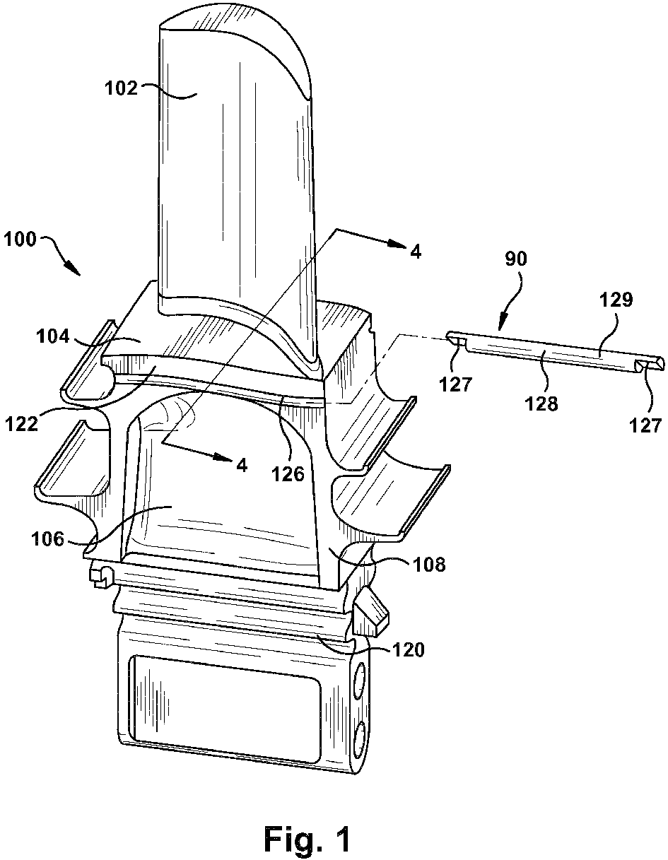
- damper system 90 for a turbine having adjacent turbine bucket platforms including opposing slash faces having opposing grooves. More specifically, damper system 90 is shown with a turbine bucket generally designated 100 including an airfoil 102, a bucket platform 104, a root portion 106 including a shank 108 and a dovetail 120. It will be appreciated that turbine bucket 100, when placed in a turbine wheel (not shown), is one of an annular array of turbine buckets secured about the periphery of the turbine wheel. While axial entry buckets are disclosed, it will be appreciated that dampening system hereof may be applied to tangential entry buckets. As illustrated best in FIG.
- adjacent turbine bucket platforms 114 include a gap 124 between slash faces 122 ( FIG. 2 ). As shown in FIGS. 1 and 2 , each slash face 122 also includes a portion of a groove 126 ( FIGS. 1 and 4 ) for receiving a damper pin 128.
- Damper pin 128 is positioned in grooves 126 of adjacent platforms 114 to dampen vibration between adjacent platforms. As illustrated in FIGS. 1 , 16 and 17 , opposite ends of pins 128 may have shaped sections 127 (omitted for clarity from other figures) for cooperating with corresponding shaped sections along slash face 122 ends to maintain orientation in grooves 126. While shaped sections 127 are illustrated as semi-cylindrical sections with flats, any of a variety of mating shapes may be employed. To accomplish the dampening, damper pin 128 cooperates with the surfaces of platforms 114 defining grooves 126 to provide various configurations of contact between grooves 126 and damper pin 128. Embodiments of the invention provide various damper pin 128 configurations to allow customization of the vibration dampening function of the damper pin.
- damper pin 128 includes, as described herein, a pin having a substantially cylindrical-shaped body 129 ( FIG. 1 ) configured for positioning in the opposing grooves 126 ( FIG. 4 ).
- damper pin 128 includes a set of slots 130 in an outer surface 132 of the pin and at spaced axial locations therealong. As shown in FIG. 5 , set of slots 130 face in a radially outward direction (up on page in all but FIG. 10 ) relative to turbine bucket platforms 114. As shown by arrow in FIG. 4 , a radial outward direction is away from platforms 114 past airfoils 102. In this fashion, set of slots 130 engage grooves 126 in such a way that customization of slots 130 acts to customize the dampening of vibrations. As will be discussed, various arrangement of slots 130 are possible according to embodiments of the invention.
- each slot 130 may include an outwardly facing surface 140.
- outwardly facing surface is planar such that outwardly facing surface 140 extends as a chord relative to the substantially cylindrical-shaped pin.
- an outwardly facing surface 240 may be inwardly concave, i.e., inwardly dished or curved in a chordal manner. While outwardly facing surfaces 140, 240 are shown as used separately, they may also be used together on a single pin 128.
- slots 130 may be uniformly spaced along pin 128. That is, a space between each adjacent pins is substantially identical, e.g., +/- 0.1 mm.
- slots 130 may be non-uniformly spaced along pin 128. That is, a space between each adjacent slots differs along longitudinal length of pin 128. In any event, the spacing can be user defined to address dampening concerns.
- slots 130 may have uniform depth into pin 128. Slots having uniform depth are shown in the embodiments of FIGS. 5-13, 16 and 17 . In an alternative embodiment, shown in FIGS.
- At least two slots 230 may have different depths into pin 128. Any number of slots 230 having different depths may be provided and arranged axially in any manner, e.g., two depths alternating, sequenced, all different depths, etc.
- a ratio of an average depth of set of slots 130, 230 to a diameter (d/D in FIG. 6 ) of the pin may range from approximately 40% to approximately 80%, e.g., +/- 1%. Although any percentage within the range is possible, as examples, FIGS. 5-6 show about 45%, FIGS. 8-9 show about 20%, FIG. 11 shows about 80% (note FIG. 10 shows a bottom view as opposed to a side view in FIGS. 12 and 14), FIGS. 12-13 show about 60% and FIGS. 14-15 show slots of varying depth within the stated range. Slots 130 may also be described as extending at about outer surface 132 of pin 128 at different angles. For example, slots 130 may extend from approximately 90° ( FIG.
- each slot 130 may extend approximately 150° about outer surface 132 of pin 128.
- each slot 130 extends approximately 320° about the outer surface 132 of pin 128.
- FIG. 11 shows pin 128 as it would be positioned during operation (see FIGS. 5 and 7 ) with slots 130 facing in the radially outward direction (up the page) relative to turbine bucket platforms 114 ( FIG. 5 ).
- a non-slotted remainder 150 of pin 128 faces the radially inward direction (down page in FIG. 11 ) relative to turbine bucket platforms 114. (In FIG. 10 , non-slotted remainder 150 faces the reader.)
- slots 130 need not have sides that extend perpendicular to an axis of pin 128.
- each slot 330 may have an internal surface 152 that is angled at a non-perpendicular angle to an axis of the pin. The angle can be user defined, e.g., 45° to 60°.
- each slot 430 may have an axially curved bottom surface 154.
- dampening system 100 and dampening pin 128 enable more contact area compared to a uniform surfaced pin, which in turn enables very good dampening from pin 128.
- Dampening pins 128 have been found to be especially effective for un-shrouded buckets where the damper pin may be the only source for dampening.
- Slots 130 may be machined into new or previously used pins 128. Hence, slots 130 can be easily retrofitted by removing material from existing damper pins to make slots 130.
Abstract
Description
- The disclosure relates to a damper system with a damper pin with slots for disposition between adjacent slash faces of turbine bucket platforms for dampening bucket vibrations thereof to meet part life requirements.
- Industrial turbines such as gas turbines have trended towards increased inlet firing temperatures and increased power output. As output has increased, gas path temperatures and operational vibrations have increased. Consequently, bucket platform slash faces have increasingly exhibited distress including oxidation, creep and low cycle fatigue cracking. Distress of the bucket platform slash faces can damage the platform and cause loss of dampening leading to damage such as compressor discharge flow leakage leading to reduced engine efficiency.
- Current turbine arrangements employ damper pins between the slash faces to dampen vibrations. Most current pins have a uniform exterior surface that engage the slash faces of turbine platforms along a line. One approach to provide cooling and some dampening employs a generally cylindrical-shaped pin having a plurality of channels formed therealong for communicating a cooling medium through the channels. The channels extend along opposite sides of the pin and are staggered. While the layout of channels in the current approach provides cooling, it may not provide adequate dampening or dampening customization.
- A first aspect of the disclosure provides a damper system for a turbine having adjacent turbine bucket platforms including opposing slash faces having opposing grooves, the system comprising: a pin having a substantially cylindrical-shaped body configured for positioning in the opposing grooves; and a set of slots in an outer surface of the pin and at spaced axial locations therealong, the set of slots facing in a radially outward direction relative to the turbine bucket platforms.
- A second aspect of the disclosure provides a damper pin for a damper system for a turbine having adjacent turbine bucket platforms having opposing slash faces having opposing grooves, the damper pin comprising: a substantially cylindrical-shaped body configured for positioning in the opposing grooves; and a set of slots in an outer surface of the body at spaced axial locations therealong, the set of slots facing in a radially outward direction relative to the turbine bucket platforms.
- The illustrative aspects of the present disclosure are arranged to solve the problems herein described and/or other problems not discussed.
- These and other features of this disclosure will be more readily understood from the following detailed description of the various aspects of the disclosure taken in conjunction with the accompanying drawings that depict various embodiments of the disclosure, in which:
-
FIG. 1 is a perspective view of a turbine bucket including an airfoil, platform and root, and a dampening system according to embodiments of the invention. -
FIG. 2 is a fragmentary perspective view illustrating a damper pin according to embodiments of the invention along a slash face of a turbine bucket platform. -
FIG. 3 is an axial end view illustrating a location of a damper pin according to embodiments of the invention between adjacent slash faces. -
FIG. 4 is a cross-sectional view along line 4-4 inFIG. 1 illustrating a damper pin between adjoining slash faces. -
FIG. 5 is an enlarged cross-sectional view illustrating slots in a damper pin for dampening vibrations according to one embodiment. -
FIG. 6 is a side view illustrating slots in a damper pin for dampening vibrations according to another embodiment. -
FIG. 7 is an enlarged cross-sectional view illustrating slots in a damper pin for dampening vibrations according to another embodiment. -
FIGS. 8 and 9 are side and cross-sectional views, respectively, illustrating one embodiment of a damper pin. -
FIGS. 10 and 11 are bottom and cross-sectional views, respectively, illustrating another embodiment of a damper pin. -
FIGS. 12 and 13 are side and cross-sectional views, respectively, illustrating another embodiment of a damper pin. -
FIGS. 14 and 15 are side and cross-sectional view, respectively, illustrating another embodiment of a damper pin. -
FIGS. 16-17 are side cross-sectional views illustrating other embodiments of a damper pin. - It is noted that the drawings of the disclosure are not to scale. The drawings are intended to depict only typical aspects of the disclosure, and therefore should not be considered as limiting the scope of the disclosure. In the drawings, like numbering represents like elements between the drawings.
- As indicated above, the disclosure provides a damper system with a damper pin with slots for disposition between adjacent slash faces of turbine bucket platforms for dampening bucket vibrations of turbine bucket platforms required to meet part life requirements. The slots face in a radially outward direction relative to the turbine bucket platforms, and can be customized to provide a desired dampening.
- Referring now to
FIG. 1 , there is illustrated adamper system 90 for a turbine having adjacent turbine bucket platforms including opposing slash faces having opposing grooves. More specifically,damper system 90 is shown with a turbine bucket generally designated 100 including anairfoil 102, abucket platform 104, aroot portion 106 including ashank 108 and adovetail 120. It will be appreciated thatturbine bucket 100, when placed in a turbine wheel (not shown), is one of an annular array of turbine buckets secured about the periphery of the turbine wheel. While axial entry buckets are disclosed, it will be appreciated that dampening system hereof may be applied to tangential entry buckets. As illustrated best inFIG. 4 , adjacentturbine bucket platforms 114 include agap 124 between slash faces 122 (FIG. 2 ). As shown inFIGS. 1 and2 , eachslash face 122 also includes a portion of a groove 126 (FIGS. 1 and4 ) for receiving adamper pin 128. -
Damper pin 128 is positioned ingrooves 126 ofadjacent platforms 114 to dampen vibration between adjacent platforms. As illustrated inFIGS. 1 ,16 and 17 , opposite ends ofpins 128 may have shaped sections 127 (omitted for clarity from other figures) for cooperating with corresponding shaped sections alongslash face 122 ends to maintain orientation ingrooves 126. Whileshaped sections 127 are illustrated as semi-cylindrical sections with flats, any of a variety of mating shapes may be employed. To accomplish the dampening,damper pin 128 cooperates with the surfaces ofplatforms 114 defininggrooves 126 to provide various configurations of contact betweengrooves 126 anddamper pin 128. Embodiments of the invention providevarious damper pin 128 configurations to allow customization of the vibration dampening function of the damper pin. - In one embodiment of the present invention,
damper pin 128 includes, as described herein, a pin having a substantially cylindrical-shaped body 129 (FIG. 1 ) configured for positioning in the opposing grooves 126 (FIG. 4 ). In addition and in contrast to conventional damper pins, as shown inFIGS. 5-6 ,damper pin 128 includes a set ofslots 130 in anouter surface 132 of the pin and at spaced axial locations therealong. As shown inFIG. 5 , set ofslots 130 face in a radially outward direction (up on page in all butFIG. 10 ) relative toturbine bucket platforms 114. As shown by arrow inFIG. 4 , a radial outward direction is away fromplatforms 114past airfoils 102. In this fashion, set ofslots 130 engagegrooves 126 in such a way that customization ofslots 130 acts to customize the dampening of vibrations. As will be discussed, various arrangement ofslots 130 are possible according to embodiments of the invention. - In some embodiments, shown in
FIGS. 5-6 and 8-17 , eachslot 130 may include an outwardly facingsurface 140. In some embodiments, shown inFIGS. 5-6 and 8-17 , outwardly facing surface is planar such that outwardly facingsurface 140 extends as a chord relative to the substantially cylindrical-shaped pin. Alternatively, as shown inFIG. 7 , an outwardly facingsurface 240 may be inwardly concave, i.e., inwardly dished or curved in a chordal manner. While outwardly facingsurfaces single pin 128. - In some embodiments, shown for example in
FIGS. 6 and10 ,slots 130 may be uniformly spaced alongpin 128. That is, a space between each adjacent pins is substantially identical, e.g., +/- 0.1 mm. However, in other embodiments, shown for example inFIGS. 8 ,12 and 14 ,slots 130 may be non-uniformly spaced alongpin 128. That is, a space between each adjacent slots differs along longitudinal length ofpin 128. In any event, the spacing can be user defined to address dampening concerns. In addition, in some embodiments,slots 130 may have uniform depth intopin 128. Slots having uniform depth are shown in the embodiments ofFIGS. 5-13, 16 and 17 . In an alternative embodiment, shown inFIGS. 14 and 15 , at least twoslots 230 may have different depths intopin 128. Any number ofslots 230 having different depths may be provided and arranged axially in any manner, e.g., two depths alternating, sequenced, all different depths, etc. - With further regard to depth of the slots, a ratio of an average depth of set of
slots FIG. 6 ) of the pin may range from approximately 40% to approximately 80%, e.g., +/- 1%. Although any percentage within the range is possible, as examples,FIGS. 5-6 show about 45%,FIGS. 8-9 show about 20%,FIG. 11 shows about 80% (noteFIG. 10 shows a bottom view as opposed to a side view inFIGS. 12 and 14), FIGS. 12-13 show about 60% andFIGS. 14-15 show slots of varying depth within the stated range.Slots 130 may also be described as extending at aboutouter surface 132 ofpin 128 at different angles. For example,slots 130 may extend from approximately 90° (FIG. 9 ) to approximately 320° (FIG. 11 ), e.g., +/- 2°. For example, as shown inFIG. 7 , eachslot 130 may extend approximately 150° aboutouter surface 132 ofpin 128. InFIGS. 10 and 11 , eachslot 130 extends approximately 320° about theouter surface 132 ofpin 128. With regard to the latter case,FIG. 11 showspin 128 as it would be positioned during operation (seeFIGS. 5 and7 ) withslots 130 facing in the radially outward direction (up the page) relative to turbine bucket platforms 114 (FIG. 5 ). Here, anon-slotted remainder 150 ofpin 128 faces the radially inward direction (down page inFIG. 11 ) relative toturbine bucket platforms 114. (InFIG. 10 ,non-slotted remainder 150 faces the reader.) - In other embodiments, shown in
FIG. 16 ,slots 130 need not have sides that extend perpendicular to an axis ofpin 128. For example, as shown inFIG. 16 , eachslot 330 may have aninternal surface 152 that is angled at a non-perpendicular angle to an axis of the pin. The angle can be user defined, e.g., 45° to 60°. In another embodiment, shown inFIG. 17 , eachslot 430 may have an axially curvedbottom surface 154. - Although the various embodiments have been shown in a particular fashion, it is emphasized that any of the above-described versions can be used together. That is, a user can select any part of any of the embodiments and combine them as required to customize the dampening provided by dampening
system 100 and dampeningpin 128. In any event,system 100 and pin 128 enable more contact area compared to a uniform surfaced pin, which in turn enables very good dampening frompin 128. Dampeningpins 128 have been found to be especially effective for un-shrouded buckets where the damper pin may be the only source for dampening.Slots 130 may be machined into new or previously used pins 128. Hence,slots 130 can be easily retrofitted by removing material from existing damper pins to makeslots 130. - The terminology used herein is for the purpose of describing particular embodiments only and is not intended to be limiting of the disclosure. As used herein, the singular forms "a", "an" and "the" are intended to include the plural forms as well, unless the context clearly indicates otherwise. It will be further understood that the terms "comprises" and/or "comprising," when used in this specification, specify the presence of stated features, integers, steps, operations, elements, and/or components, but do not preclude the presence or addition of one or more other features, integers, steps, operations, elements, components, and/or groups thereof.
- The corresponding structures, materials, acts, and equivalents of all means or step plus function elements in the claims below are intended to include any structure, material, or act for performing the function in combination with other claimed elements as specifically claimed. The description of the present disclosure has been presented for purposes of illustration and description, but is not intended to be exhaustive or limited to the disclosure in the form disclosed. Many modifications and variations will be apparent to those of ordinary skill in the art without departing from the scope and spirit of the disclosure. The embodiment was chosen and described in order to best explain the principles of the disclosure and the practical application, and to enable others of ordinary skill in the art to understand the disclosure for various embodiments with various modifications as are suited to the particular use contemplated.
Claims (10)
- A damper system (90) for a turbine having adjacent turbine bucket platforms (104) including opposing slash faces (122) having opposing grooves (126), the system comprising:a pin having a substantially cylindrical-shaped body (129) configured for positioning in the opposing grooves (126); anda set of slots (130, 230) in an outer surface (132) of the pin and at spaced axial locations therealong, the set of slots (130, 230) facing in a radially outward direction relative to the turbine bucket platforms (104).
- The damper system (90) of claim 1, wherein the set of slots (130, 230) are uniformly spaced along the pin.
- The damper system (90) of claim 1, wherein the set of slots (130, 230) are non-uniformly spaced along the pin.
- The damper system (90) of claim 1, 2 or 3, wherein the each slot includes an outwardly facing surface (140, 240), wherein the outwardly facing surface (140, 240) is planar such that the outwardly facing surface (140, 240) extends as a chord relative to the substantially cylindrical-shaped pin.
- The damper system (90) of claim 1, 2 or 3, wherein the set of slots (130, 230) each include an outwardly facing surface (140, 240), and wherein the outwardly facing surface (140, 240) is inwardly concave.
- The damper system (90) of any of claims 1 to 5, wherein each slot extends approximately 150° about the outer surface (132) of the pin.
- The damper system (90) of any of claims 1 to 5, wherein each slot extends approximately 320° about the outer surface (132) of the pin, and wherein the set of slots (130, 230) face in the radially outward direction relative to the turbine bucket platforms (104), and a non-slotted remainder (150) of the pin faces the radially inward direction relative to the turbine bucket platforms (104).
- The damper system (90) of any preceding claim, wherein each slot has an internal surface (152) that is angled at a non-perpendicular angle to an axis of the pin.
- The damper system (90) of any preceding claim, wherein each slot has axially curved bottom surface (154).
- The damper system (90) of any preceding claim, wherein the set of slots (130, 230) include at least two slots (130, 230) having different depths into the pin.
Applications Claiming Priority (1)
| Application Number | Priority Date | Filing Date | Title |
|---|---|---|---|
| IN2438CH2015 | 2015-05-14 |
Publications (1)
| Publication Number | Publication Date |
|---|---|
| EP3093439A1 true EP3093439A1 (en) | 2016-11-16 |
Family
ID=55913540
Family Applications (1)
| Application Number | Title | Priority Date | Filing Date |
|---|---|---|---|
| EP16168466.7A Pending EP3093439A1 (en) | 2015-05-14 | 2016-05-05 | Damper system |
Country Status (4)
| Country | Link |
|---|---|
| US (1) | US9879548B2 (en) |
| EP (1) | EP3093439A1 (en) |
| JP (1) | JP6882819B2 (en) |
| CN (1) | CN106150560B (en) |
Cited By (6)
| Publication number | Priority date | Publication date | Assignee | Title |
|---|---|---|---|---|
| EP3138999A1 (en) * | 2015-09-03 | 2017-03-08 | General Electric Company | Damper pin for turbine blades and corresponding turbine engine |
| US10385701B2 (en) | 2015-09-03 | 2019-08-20 | General Electric Company | Damper pin for a turbine blade |
| US10443408B2 (en) | 2015-09-03 | 2019-10-15 | General Electric Company | Damper pin for a turbine blade |
| US10472975B2 (en) | 2015-09-03 | 2019-11-12 | General Electric Company | Damper pin having elongated bodies for damping adjacent turbine blades |
| US10584597B2 (en) | 2015-09-03 | 2020-03-10 | General Electric Company | Variable cross-section damper pin for a turbine blade |
| US11149585B2 (en) | 2018-05-24 | 2021-10-19 | MTU Aero Engines AG | Turbomachine assembly with a detuning device for different detuning of natural frequencies of the blades |
Families Citing this family (6)
| Publication number | Priority date | Publication date | Assignee | Title |
|---|---|---|---|---|
| US11118458B2 (en) * | 2017-10-27 | 2021-09-14 | MTU Aero Engines AG | Combination for sealing a gap between turbomachine blades and for reducing vibrations of the turbomachine blades |
| JP7020977B2 (en) * | 2018-03-28 | 2022-02-16 | 三菱重工業株式会社 | Rotating machine |
| JP6991912B2 (en) | 2018-03-28 | 2022-01-13 | 三菱重工業株式会社 | Rotating machine |
| JP6985197B2 (en) * | 2018-03-28 | 2021-12-22 | 三菱重工業株式会社 | Rotating machine |
| JP7039355B2 (en) | 2018-03-28 | 2022-03-22 | 三菱重工業株式会社 | Rotating machine |
| JP2023093088A (en) | 2021-12-22 | 2023-07-04 | 三菱重工業株式会社 | rotary machine |
Citations (7)
| Publication number | Priority date | Publication date | Assignee | Title |
|---|---|---|---|---|
| JPH07305602A (en) * | 1994-05-12 | 1995-11-21 | Mitsubishi Heavy Ind Ltd | Cooling device for platform of gas turbine moving blade |
| EP1452692A2 (en) * | 2003-02-27 | 2004-09-01 | General Electric Company | Turbine bucket damper pin |
| US20060110255A1 (en) * | 2004-11-24 | 2006-05-25 | General Electric Company | Controlled leakage pin and vibration damper for active cooling and purge of bucket slash faces |
| EP2110515A2 (en) * | 2008-04-16 | 2009-10-21 | Rolls-Royce plc | Cooling arrangement between two blade platforms for a gas turbine engine |
| US20100124508A1 (en) * | 2006-09-22 | 2010-05-20 | Siemens Power Generation, Inc. | Turbine airfoil cooling system with platform edge cooling channels |
| EP2500525A1 (en) * | 2011-03-15 | 2012-09-19 | United Technologies Corporation | Damper pin |
| EP2738353A2 (en) * | 2012-11-28 | 2014-06-04 | General Electric Company | System for damping vibrations in a turbine |
Family Cites Families (5)
| Publication number | Priority date | Publication date | Assignee | Title |
|---|---|---|---|---|
| US4936749A (en) * | 1988-12-21 | 1990-06-26 | General Electric Company | Blade-to-blade vibration damper |
| US5827047A (en) | 1996-06-27 | 1998-10-27 | United Technologies Corporation | Turbine blade damper and seal |
| US6851932B2 (en) * | 2003-05-13 | 2005-02-08 | General Electric Company | Vibration damper assembly for the buckets of a turbine |
| US8790086B2 (en) * | 2010-11-11 | 2014-07-29 | General Electric Company | Turbine blade assembly for retaining sealing and dampening elements |
| US8951014B2 (en) | 2011-03-15 | 2015-02-10 | United Technologies Corporation | Turbine blade with mate face cooling air flow |
-
2015
- 2015-08-11 US US14/823,604 patent/US9879548B2/en active Active
-
2016
- 2016-05-05 EP EP16168466.7A patent/EP3093439A1/en active Pending
- 2016-05-10 JP JP2016094214A patent/JP6882819B2/en active Active
- 2016-05-13 CN CN201610314551.4A patent/CN106150560B/en active Active
Patent Citations (7)
| Publication number | Priority date | Publication date | Assignee | Title |
|---|---|---|---|---|
| JPH07305602A (en) * | 1994-05-12 | 1995-11-21 | Mitsubishi Heavy Ind Ltd | Cooling device for platform of gas turbine moving blade |
| EP1452692A2 (en) * | 2003-02-27 | 2004-09-01 | General Electric Company | Turbine bucket damper pin |
| US20060110255A1 (en) * | 2004-11-24 | 2006-05-25 | General Electric Company | Controlled leakage pin and vibration damper for active cooling and purge of bucket slash faces |
| US20100124508A1 (en) * | 2006-09-22 | 2010-05-20 | Siemens Power Generation, Inc. | Turbine airfoil cooling system with platform edge cooling channels |
| EP2110515A2 (en) * | 2008-04-16 | 2009-10-21 | Rolls-Royce plc | Cooling arrangement between two blade platforms for a gas turbine engine |
| EP2500525A1 (en) * | 2011-03-15 | 2012-09-19 | United Technologies Corporation | Damper pin |
| EP2738353A2 (en) * | 2012-11-28 | 2014-06-04 | General Electric Company | System for damping vibrations in a turbine |
Cited By (6)
| Publication number | Priority date | Publication date | Assignee | Title |
|---|---|---|---|---|
| EP3138999A1 (en) * | 2015-09-03 | 2017-03-08 | General Electric Company | Damper pin for turbine blades and corresponding turbine engine |
| US10385701B2 (en) | 2015-09-03 | 2019-08-20 | General Electric Company | Damper pin for a turbine blade |
| US10443408B2 (en) | 2015-09-03 | 2019-10-15 | General Electric Company | Damper pin for a turbine blade |
| US10472975B2 (en) | 2015-09-03 | 2019-11-12 | General Electric Company | Damper pin having elongated bodies for damping adjacent turbine blades |
| US10584597B2 (en) | 2015-09-03 | 2020-03-10 | General Electric Company | Variable cross-section damper pin for a turbine blade |
| US11149585B2 (en) | 2018-05-24 | 2021-10-19 | MTU Aero Engines AG | Turbomachine assembly with a detuning device for different detuning of natural frequencies of the blades |
Also Published As
| Publication number | Publication date |
|---|---|
| US9879548B2 (en) | 2018-01-30 |
| JP6882819B2 (en) | 2021-06-02 |
| CN106150560B (en) | 2020-06-09 |
| JP2016217349A (en) | 2016-12-22 |
| US20160333704A1 (en) | 2016-11-17 |
| CN106150560A (en) | 2016-11-23 |
Similar Documents
| Publication | Publication Date | Title |
|---|---|---|
| US9879548B2 (en) | Turbine blade damper system having pin with slots | |
| EP2823151B1 (en) | Airfoil with improved internal cooling channel pedestals | |
| US9127556B2 (en) | Rotor disc and method of balancing | |
| US7901180B2 (en) | Enhanced turbine airfoil cooling | |
| EP2472065B1 (en) | Damper coverplate and sealing arrangement for turbine bucket shank | |
| US8951013B2 (en) | Turbine blade rail damper | |
| EP3139003B1 (en) | Damper pin for turbine blades and corresponding turbine engine | |
| EP3139001B1 (en) | Damper pin for turbine blades and corresponding turbine engine | |
| EP2500520A2 (en) | Damper and seal pin arrangement for a turbine blade | |
| RU2398113C2 (en) | Turbine wheel (versions) and attachment of turbine wheel and vane | |
| US10577936B2 (en) | Mateface surfaces having a geometry on turbomachinery hardware | |
| EP3835548A1 (en) | Turbomachine with damper stacks | |
| EP3835550A1 (en) | Turbomachine with damper stacks | |
| WO2014105103A1 (en) | Platform with curved edges | |
| US9739159B2 (en) | Method and system for relieving turbine rotor blade dovetail stress | |
| EP3070274A1 (en) | Turbine blade assembly with cooled platform | |
| US8956116B2 (en) | Cooling of a gas turbine component designed as a rotor disk or turbine blade | |
| EP3722555A1 (en) | Turbine section having non-axisymmetric endwall contouring with forward mid-passage peak | |
| EP2372091B1 (en) | Airfoil of a turbine engine | |
| US10012096B2 (en) | Turbine with bucket fixing means | |
| EP2669477A1 (en) | Shroud for airfoils | |
| EP2863016A1 (en) | Turbine with bucket fixing means | |
| EP2997230B1 (en) | Tangential blade root neck conic | |
| WO2016195689A1 (en) | Attachment system for turbine engine airfoil | |
| JP2005299614A (en) | Turbine bucket and turbine using the same |
Legal Events
| Date | Code | Title | Description |
|---|---|---|---|
| PUAI | Public reference made under article 153(3) epc to a published international application that has entered the european phase |
Free format text: ORIGINAL CODE: 0009012 |
|
| AK | Designated contracting states |
Kind code of ref document: A1 Designated state(s): AL AT BE BG CH CY CZ DE DK EE ES FI FR GB GR HR HU IE IS IT LI LT LU LV MC MK MT NL NO PL PT RO RS SE SI SK SM TR |
|
| AX | Request for extension of the european patent |
Extension state: BA ME |
|
| STAA | Information on the status of an ep patent application or granted ep patent |
Free format text: STATUS: REQUEST FOR EXAMINATION WAS MADE |
|
| 17P | Request for examination filed |
Effective date: 20170516 |
|
| RBV | Designated contracting states (corrected) |
Designated state(s): AL AT BE BG CH CY CZ DE DK EE ES FI FR GB GR HR HU IE IS IT LI LT LU LV MC MK MT NL NO PL PT RO RS SE SI SK SM TR |
|
| STAA | Information on the status of an ep patent application or granted ep patent |
Free format text: STATUS: EXAMINATION IS IN PROGRESS |
|
| 17Q | First examination report despatched |
Effective date: 20180124 |
|
| STAA | Information on the status of an ep patent application or granted ep patent |
Free format text: STATUS: EXAMINATION IS IN PROGRESS |
|
| RAP1 | Party data changed (applicant data changed or rights of an application transferred) |
Owner name: GENERAL ELECTRIC TECHNOLOGY GMBH |
|
| GRAP | Despatch of communication of intention to grant a patent |
Free format text: ORIGINAL CODE: EPIDOSNIGR1 |
|
| STAA | Information on the status of an ep patent application or granted ep patent |
Free format text: STATUS: GRANT OF PATENT IS INTENDED |
|
| INTG | Intention to grant announced |
Effective date: 20240116 |