EP3093421A1 - Latch device - Google Patents
Latch device Download PDFInfo
- Publication number
- EP3093421A1 EP3093421A1 EP15735550.4A EP15735550A EP3093421A1 EP 3093421 A1 EP3093421 A1 EP 3093421A1 EP 15735550 A EP15735550 A EP 15735550A EP 3093421 A1 EP3093421 A1 EP 3093421A1
- Authority
- EP
- European Patent Office
- Prior art keywords
- rod
- case
- slide
- cam
- rotation
- Prior art date
- Legal status (The legal status is an assumption and is not a legal conclusion. Google has not performed a legal analysis and makes no representation as to the accuracy of the status listed.)
- Granted
Links
Images




Classifications
-
- E—FIXED CONSTRUCTIONS
- E05—LOCKS; KEYS; WINDOW OR DOOR FITTINGS; SAFES
- E05C—BOLTS OR FASTENING DEVICES FOR WINGS, SPECIALLY FOR DOORS OR WINDOWS
- E05C19/00—Other devices specially designed for securing wings, e.g. with suction cups
- E05C19/02—Automatic catches, i.e. released by pull or pressure on the wing
-
- E—FIXED CONSTRUCTIONS
- E05—LOCKS; KEYS; WINDOW OR DOOR FITTINGS; SAFES
- E05B—LOCKS; ACCESSORIES THEREFOR; HANDCUFFS
- E05B83/00—Vehicle locks specially adapted for particular types of wing or vehicle
- E05B83/28—Locks for glove compartments, console boxes, fuel inlet covers or the like
- E05B83/34—Locks for glove compartments, console boxes, fuel inlet covers or the like for fuel inlet covers essentially flush with the vehicle surface
-
- B—PERFORMING OPERATIONS; TRANSPORTING
- B60—VEHICLES IN GENERAL
- B60K—ARRANGEMENT OR MOUNTING OF PROPULSION UNITS OR OF TRANSMISSIONS IN VEHICLES; ARRANGEMENT OR MOUNTING OF PLURAL DIVERSE PRIME-MOVERS IN VEHICLES; AUXILIARY DRIVES FOR VEHICLES; INSTRUMENTATION OR DASHBOARDS FOR VEHICLES; ARRANGEMENTS IN CONNECTION WITH COOLING, AIR INTAKE, GAS EXHAUST OR FUEL SUPPLY OF PROPULSION UNITS IN VEHICLES
- B60K15/00—Arrangement in connection with fuel supply of combustion engines or other fuel consuming energy converters, e.g. fuel cells; Mounting or construction of fuel tanks
- B60K15/03—Fuel tanks
- B60K15/04—Tank inlets
- B60K15/05—Inlet covers
-
- E—FIXED CONSTRUCTIONS
- E05—LOCKS; KEYS; WINDOW OR DOOR FITTINGS; SAFES
- E05B—LOCKS; ACCESSORIES THEREFOR; HANDCUFFS
- E05B85/00—Details of vehicle locks not provided for in groups E05B77/00 - E05B83/00
- E05B85/02—Lock casings
-
- E—FIXED CONSTRUCTIONS
- E05—LOCKS; KEYS; WINDOW OR DOOR FITTINGS; SAFES
- E05C—BOLTS OR FASTENING DEVICES FOR WINGS, SPECIALLY FOR DOORS OR WINDOWS
- E05C19/00—Other devices specially designed for securing wings, e.g. with suction cups
- E05C19/02—Automatic catches, i.e. released by pull or pressure on the wing
- E05C19/022—Released by pushing in the closing direction
-
- E—FIXED CONSTRUCTIONS
- E05—LOCKS; KEYS; WINDOW OR DOOR FITTINGS; SAFES
- E05C—BOLTS OR FASTENING DEVICES FOR WINGS, SPECIALLY FOR DOORS OR WINDOWS
- E05C19/00—Other devices specially designed for securing wings, e.g. with suction cups
- E05C19/02—Automatic catches, i.e. released by pull or pressure on the wing
- E05C19/028—Automatic catches, i.e. released by pull or pressure on the wing with sliding bolt(s)
-
- B—PERFORMING OPERATIONS; TRANSPORTING
- B60—VEHICLES IN GENERAL
- B60K—ARRANGEMENT OR MOUNTING OF PROPULSION UNITS OR OF TRANSMISSIONS IN VEHICLES; ARRANGEMENT OR MOUNTING OF PLURAL DIVERSE PRIME-MOVERS IN VEHICLES; AUXILIARY DRIVES FOR VEHICLES; INSTRUMENTATION OR DASHBOARDS FOR VEHICLES; ARRANGEMENTS IN CONNECTION WITH COOLING, AIR INTAKE, GAS EXHAUST OR FUEL SUPPLY OF PROPULSION UNITS IN VEHICLES
- B60K15/00—Arrangement in connection with fuel supply of combustion engines or other fuel consuming energy converters, e.g. fuel cells; Mounting or construction of fuel tanks
- B60K15/03—Fuel tanks
- B60K15/04—Tank inlets
- B60K15/05—Inlet covers
- B60K2015/0515—Arrangements for closing or opening of inlet cover
- B60K2015/053—Arrangements for closing or opening of inlet cover with hinged connection to the vehicle body
-
- B—PERFORMING OPERATIONS; TRANSPORTING
- B60—VEHICLES IN GENERAL
- B60K—ARRANGEMENT OR MOUNTING OF PROPULSION UNITS OR OF TRANSMISSIONS IN VEHICLES; ARRANGEMENT OR MOUNTING OF PLURAL DIVERSE PRIME-MOVERS IN VEHICLES; AUXILIARY DRIVES FOR VEHICLES; INSTRUMENTATION OR DASHBOARDS FOR VEHICLES; ARRANGEMENTS IN CONNECTION WITH COOLING, AIR INTAKE, GAS EXHAUST OR FUEL SUPPLY OF PROPULSION UNITS IN VEHICLES
- B60K15/00—Arrangement in connection with fuel supply of combustion engines or other fuel consuming energy converters, e.g. fuel cells; Mounting or construction of fuel tanks
- B60K15/03—Fuel tanks
- B60K15/04—Tank inlets
- B60K15/05—Inlet covers
- B60K2015/0561—Locking means for the inlet cover
-
- B—PERFORMING OPERATIONS; TRANSPORTING
- B60—VEHICLES IN GENERAL
- B60K—ARRANGEMENT OR MOUNTING OF PROPULSION UNITS OR OF TRANSMISSIONS IN VEHICLES; ARRANGEMENT OR MOUNTING OF PLURAL DIVERSE PRIME-MOVERS IN VEHICLES; AUXILIARY DRIVES FOR VEHICLES; INSTRUMENTATION OR DASHBOARDS FOR VEHICLES; ARRANGEMENTS IN CONNECTION WITH COOLING, AIR INTAKE, GAS EXHAUST OR FUEL SUPPLY OF PROPULSION UNITS IN VEHICLES
- B60K15/00—Arrangement in connection with fuel supply of combustion engines or other fuel consuming energy converters, e.g. fuel cells; Mounting or construction of fuel tanks
- B60K15/03—Fuel tanks
- B60K15/04—Tank inlets
- B60K15/05—Inlet covers
- B60K2015/0561—Locking means for the inlet cover
- B60K2015/0576—Locking means for the inlet cover with actuator fixed to the vehicle body
-
- B—PERFORMING OPERATIONS; TRANSPORTING
- B60—VEHICLES IN GENERAL
- B60K—ARRANGEMENT OR MOUNTING OF PROPULSION UNITS OR OF TRANSMISSIONS IN VEHICLES; ARRANGEMENT OR MOUNTING OF PLURAL DIVERSE PRIME-MOVERS IN VEHICLES; AUXILIARY DRIVES FOR VEHICLES; INSTRUMENTATION OR DASHBOARDS FOR VEHICLES; ARRANGEMENTS IN CONNECTION WITH COOLING, AIR INTAKE, GAS EXHAUST OR FUEL SUPPLY OF PROPULSION UNITS IN VEHICLES
- B60K15/00—Arrangement in connection with fuel supply of combustion engines or other fuel consuming energy converters, e.g. fuel cells; Mounting or construction of fuel tanks
- B60K15/03—Fuel tanks
- B60K15/04—Tank inlets
- B60K15/05—Inlet covers
- B60K2015/0561—Locking means for the inlet cover
- B60K2015/0584—Locking means for the inlet cover the locking bolt is linearly moved to lock or unlock
Definitions
- the present invention relates to a latch device for retaining a member, attached so as to be capable of opening and closing, in a closed position.
- JP-U Japanese Utility Model Application Laid-Open
- This conventional technology includes a tube shaped body, a sleeve that is housed inside the body and has a sleeve jutting out portion that is a portion jutting out from the body, a shaft having a portion housed inside the body and another portion configured as an anchor head that passes through the sleeve and juts out therefrom, and a shaft rotation means that rotates the shaft by a specific angle each time the sleeve jutting out portion is pressed in toward the inside of the body.
- biasing force (load) of a compression coil for anchoring a rotor (rotation cam), configuring a shaft rotation means, in an anchor groove acts directly on the shaft.
- a high load accordingly acts on an increased diameter head of the shaft when disengaging from the groove of a dial cover by rotation.
- the durability of the latch device drops as a result.
- an object of the present invention is to obtain a latch device that is able to prevent a drop in durability due to a high load.
- a latch device of a first aspect of the present invention includes: a tube shaped case that is fixed at a side of a second member that faces a first member; a rod that is retained inside the case so as to be capable of sliding, and that juts out from inside the case to adopt an advanced position pushing out the first member; a rod biasing member that is positioned between the case and the rod, and that is compressed under elastic deformation inside the case, so as to bias the rod in a jutting out direction pushing the rod out from inside the case; a lock mechanism including: a slide cam that moves together with the rod in the jutting out direction, and a rotation cam that is provided at a rear side of the slide cam in the jutting out direction and that is capable of relative rotation with respect to the slide cam about an axis of the rod, with the lock mechanism positioned between the case and the rod, and locking the rod in a retracted position in the case due to the rotation cam engaging with the slide cam and rotating due to the rod being pressed in against a biasing force of
- the rod rotates about the axial direction thereof when the rod is advancing or retracting due to the guide mechanism provided at the rod and the case.
- the engagement portion provided at the rod disengages from the engaged portion of the first member by the rod rotating about the axial direction thereof.
- the rod biasing member positioned between the tube shaped case fixed to the side of the second member that faces the first member, and the rod that is retained inside the case so as to be capable of sliding and that juts out from inside the case to adopt an advanced position pushing out the first member, is compressed by elastic deformation inside the case so as to bias the rod in the jutting out direction so as to push out from inside the case.
- the rotation cam engages with the slide cam and rotates, such that the rod adopts a locked state in a retracted position due to the lock mechanism positioned between the case and the rod.
- the biasing force of the rod biasing member does not act directly on the engagement portion and the guide groove. As a result, a drop in the durability due to high load can be prevented.
- the latch device of a second aspect of the present invention is the latch device of the first aspect, wherein the lock mechanism further includes: a jutting out portion that is positioned partway along an axial direction of the rod and that juts out in a radial direction toward an outer side; a lower-side rod section positioned at the rear side in the jutting out direction with the jutting out portion as a boundary, so as to be capable of sliding in the axial direction, the lower-side rod section supporting the slide cam, and supporting the rotation cam at the rear side of the slide cam in the jutting out direction such that the rotation cam is capable of rotating and capable of sliding in the axial direction, and the rotation cam meshing with the slide cam, and disengaging and being imparted with a rotation force in one direction by sliding of the rod; a slide groove that is positioned at one of an outer peripheral face of the slide cam or an inner peripheral face of the case, and that extends along a slide direction of the rod, a slide projection that is positioned at another of the outer peripheral face
- the lock mechanism is a rotation cam type lock mechanism configured by a jutting out portion, a slide cam, a rotation cam, a slide groove, a slide projection, an engagement projection, a lock groove, a sleeve, and a grommet. Switching between locking and unlocking is achieved by the rotation cam being operated by the rod being pressed in. Switching between locking and unlocking is accordingly reliably achieved.
- the latch device of a third aspect of the present invention is the latch device of the first aspect or the second aspect, further comprising a boot that is provided between the engagement portion and the case, and that covers the rod.
- a latch device of a fourth aspect of the present invention is the latch device of the third aspect, further including a slide resistance reduction member that is provided between the rod and the boot to reduce slide resistance between the rod and the boot.
- the slide resistance between the rod and the boot is reduced due to the slide resistance reduction member provided between the rod and the boot.
- the rotatability of the rod with respect to the boot is improved as a result.
- the latch device of a fifth aspect of the present invention is the latch device of any one of the first aspect to the fourth aspect, wherein the second member is a vehicle body, and the first member is a fuel lid attached to the vehicle body so as to be capable of rotating in opening and closing directions.
- the excellent operation and advantageous effects described above are exhibited in a fuel lid attached to a vehicle body so as to be capable of rotating in opening and closing directions.
- the latch device of the second aspect of the present invention due to configuration as described above, a drop in the durability of the latch device due to high load can be prevented, and switching between locking and unlocking is reliably achieved.
- the rotatability of the rod with respect to the boot can be improved.
- the latch device of the fifth aspect of the present invention due to configuration as described above, a drop in durability due to high load acting on a fuel lid, attached to a vehicle body so as to be capable of rotating in opening and closing directions, can be prevented.
- a latch device 10 of the present exemplary embodiment is provided, for example, on a vehicle body of a car, to a vehicle body inner panel 14, serving as a second member, facing a fuel lid 12, serving as a first member.
- the fuel lid 12 is attached to the inner panel 14 by a hinge, not illustrated in the drawings, so as to be capable of swinging in opening or closing directions, such that the fuel lid 12 is retained in the closed position illustrated in Fig. 2 , or is pushed out in a jutting out direction (the arrow A direction in Fig. 2 ) that is the opening direction, by the latch device 10.
- the latch device 10 includes a case 16, a rod 20, a jutting out portion 64 of the rod 20 serving as a lock mechanism, a cap 18, a slide cam 21, a rotation cam 22, a sleeve 120, a grommet 122, a first spring 25, a second spring 26 serving as a rod biasing member, and a boot 28.
- the first spring 25 and the second spring 26 are, as an example, configured by coiled springs, and the biasing force (load) of the first spring 25 is set smaller (lighter) than the biasing force (load) of the second spring 26.
- the case 16 is formed in a tube shape. As illustrated in Fig. 2 , an attachment hole 32 is formed in the inner panel 14 so as to pierce through the front and back faces thereof, and the case 16 is fixed to the attachment hole 32.
- the case 16 is formed in circular cylinder shape that is open at the upper face and formed with a bottom face.
- the external diameter of the case 16 is set so as to be the internal diameter of the attachment hole 32 in the inner panel 14, or less.
- a flange 34 is formed to an end portion on the open side of the case 16 so as to extend in radial direction toward the outer side, and a ring shaped attachment portion 36 is formed at the upper side of the flange 34.
- Plural elastically deformable elastic claws 38 are formed at the lower side of the flange 34, jutting out in a radial pattern from the outer periphery of the case 16. These elastic claws 38 are provided at a distance from the lower face of the flange 34 so as to maintain a separation thereto of the plate thickness of the inner panel 14.
- the cap 18 is attached to the open upper face of the case 16, and configures part of the case 16.
- the cap 18 includes a lid portion 40 that is slightly bigger than the open upper face of the case 16, and a circular tube portion 42 that is one step narrower than, and extends in circular tube shape from, the lower face of the lid portion 40.
- a circular shaped through hole 44 is formed piercing through an inner peripheral portion of the lid portion 40 of the cap 18, from top to bottom.
- the rod 20 is inserted into the through hole 44.
- Projections 45 serving as a guide mechanism, are formed so as to jut out from inner peripheral portions of the through hole 44.
- the circular tube portion 42 of the cap 18 is set with an outer circumference having the internal diameter of the case 16 or smaller, and is inserted into the case 16.
- Plural elastically deformable anchor claws 46 are formed jutting out in a radial pattern on the outer periphery of the circular tube portion 42 of the cap 18, at locations adjacent to the lid portion 40.
- plural anchor holes 48 are formed in the attachment portion 36 of the case 16, piercing through from the inside to the outside, such that the anchor claws 46 of the cap 18 fit into the anchor holes 48 of the case 16.
- the anchor claws 46 are temporarily pushed in, and then the anchor claws 46 elastically fit into the anchor holes 48 so as to fix the cap 18 to the case 16.
- recessed slide grooves 50 are formed in an inner peripheral face of the circular tube portion 42 of the cap 18.
- the slide grooves 50 retain the slide cam 21 so as be capable of sliding.
- a plurality of the slide grooves 50 are formed with blind upper end portions, and open lower end portions.
- Lock mechanisms 52 are provided at the lower side of the slide grooves 50, as recesses formed in the inner peripheral face of the circular tube portion 42, such that the lock mechanisms 52 lock the rotation cam 22 so as to render it non-rotatable.
- the lock mechanisms 52 are formed in the spacing between adjacent of the slide grooves 50, and are formed as saw tooth shapes along the circumferential direction on the inner peripheral face of the circular tube portion 42.
- the lock mechanisms 52 each include: a first sloping face portion 52A that slopes upwards (in the push-out direction of the rod) from the slide groove 50 on progression toward the front in a rotation direction of the rotation cam 22 (the direction of arrow B in Fig. 4 to Fig.
- a lock portion 52B positioned at a slope upper end portion of the first sloping face portion 52A, namely, positioned in front thereof in the rotation direction of the rotation cam 22, with an engagement projection 56 of the rotation cam 22, described later, fitted therein; a vertically ascending vertical portion 52C descending downwards from the lock portion 52B; and an upward sloping second sloping face portion 52D sloping upwards from a lower end portion of the vertical portion 52C, with an slope upper end portion that faces another of the slide grooves 50 positioned in front in the rotation direction of the rotation cam 22.
- a slope lower end portion of the first sloping face portion 54 namely at the rear thereof in the rotation direction of the rotation cam 22, faces the one slide groove 50.
- the slope angles are the same for the first sloping face portions 52A and the second sloping face portions 52D.
- the rod 20 is retained inside the case 16 so as to be capable of sliding, and juts out from inside the case 16 to adopt an advanced position, so as to push out the fuel lid 12, as illustrated in Fig. 2 .
- the rod 20 is formed in a circular rod shape and includes: the circular plate shaped jutting out portion 64 that is positioned at an intermediate portion in the axial direction and juts outward in radial directions; an upper-side rod section 66 that is positioned at the upper side of the jutting out portion 64 and juts out from inside the case 16 so as to push out the fuel lid 12; and a lower-side rod section 68 that is positioned at the lower side of the jutting out portion 64 and is inserted through the second spring 26.
- the jutting out portion 64 of the rod 20 abuts a portion in the vicinity of the lower periphery of the through hole 44 in the lid portion 40 of the cap 18, such that movement of the rod 20 in the push-up direction is prevented.
- the slide cam 21 having the lower-side rod section 68 inserted therethrough is disposed at the lower side of the jutting out portion 64, i.e. at a position to the rear thereof in the jutting out direction of the rod 20.
- Fixed-side cams 72 are formed on the lower face of the slide cam 21, and the fixed-side cams 72 mesh with movable-side cams 82 of the rotation cam 22, described later.
- the fixed-side cams 72 are formed continuously around the circumferential direction on the lower face of the slide cam 21, so as to form obtuse angled saw tooth shapes.
- Plural sliding projections 74 are formed at the outer periphery of the slide cam 21, jutting out in a radial pattern.
- the slide cam 21 Due to the sliding projections 74 of the slide cam 21 fitting into the slide grooves 50 of the cap 18, and the sliding projections 74 ascending or descending along the slide grooves 50, the slide cam 21 is retained inside the cap 18 so as to be capable of sliding, but not capable of rotating.
- an engagement portion 67 is formed at an upper end of the rod 20, this being a leading end portion of the upper-side rod section 66.
- Guide grooves 75 serving as a guide mechanism, are formed in a spiral shape at a length direction intermediate portion of the upper-side rod section 66 of the rod 20. The rod 20 rotates about the axial direction thereof when the rod 20 advances or retracts due to sliding movement between the guide grooves 75 and the projections 45, serving as a guide mechanism of the cap 18.
- the engagement portion 67 of the rod 20 has a bar shape extending in a direction orthogonal to the axial direction of the rod 20.
- the engagement portion 67 rotates about the axial direction, so as to be engaged, or disengaged, in an engagement hole 69A of a retainer 69, serving as engaged portion, attached to the back face of the fuel lid 12.
- the engagement hole 69A is an elongated hole formed in an upper wall portion of a retainer body 69B.
- the retainer body 69B of the retainer 69 is configured with a cap shape, so as to cover an upper portion of the boot 28.
- An engagement portion 69C is provided so as to extend upward from an upper wall portion of the retainer body 69B, such that the retainer 69 can be attached to the fuel lid 12 by engaging the engagement portion 69C in an attachment hole 13 of the fuel lid 12.
- a ring shaped annular groove 76 for attaching the boot 28 is formed in the vicinity of the upper end of the upper-side rod section 66 of the rod 20.
- a constricted portion 80 is formed at a lower end portion of the lower-side rod section 68 of the rod 20, narrowing so as to fit into a reduced diameter portion 122B of the grommet 122, described later.
- the height of the constricted portion 80 of the rod 20 is set so as to be higher than the thickness in the up-down direction of the reduced diameter portion 122B of the grommet 122. This thereby achieves a configuration in which there is a clearance in the height direction of the constricted portion 80 in a state in which the constricted portion 80 is fitted into the reduced diameter portion 122B.
- the reduced diameter portion 122B of the grommet 122 is able to ascend or descend up or down by the clearance amount to the constricted portion 80 of the rod 20.
- the rod 20 is able to ascend or descend up or down with respect to the grommet 122 by the clearance amount.
- the amount of clearance is set according to the ascent or descent amount of the rotation cam 22 referred to above as it ascends or descends between a first height position in which the movable-side cams 82 of the rotation cam 22, described later, are meshed with the fixed-side cams 72 of the slide cam 21, and a second height position in which the movable-side cams 82 are disengaged from the fixed-side cams 72.
- the sleeve 120 includes a sleeve main body 120A, and a flange 120B, and the grommet 122 includes a grommet main body 122A, the reduced diameter portion 122B, and slits 122C.
- the lower-side rod section 68 of the rod 20 is inserted through the sleeve 120, and the sleeve 120 is positioned between the rotation cam 22 and the second spring 26.
- the lower-side rod section 68 of the rod 20 is inserted through the grommet 122, and the grommet 122 is positioned at the lower side of the sleeve 120.
- the sleeve main body 120A of the sleeve 120 and the grommet main body 122A of the grommet 122 are formed in tube shapes, and have the lower-side rod section 68 inserted therethrough.
- the flange 120B of the sleeve 120 is positioned at an upper end portion of the sleeve main body 120A, abutting the rotation cam 22, and extending in radial directions both outwards and inwards.
- the reduced diameter portion 122B of the grommet 122 is positioned at a lower end portion of the grommet main body 122A at the opposite side to the upper end portion thereof, and juts out inward in radial directions.
- Two pairs of the slits 122C are formed in the diameter direction of the grommet main body 122A, such that the slits 122C divide the lower end portion of the grommet main body 122A into plural divisions.
- the slits 122C are formed from the end face at the lower side of the grommet main body 122A, upward to partway along the grommet main body 122A.
- the first spring 25 is positioned between the grommet 122 and the sleeve 120, is compressed between the grommet main body 122A of the grommet 122 and the inner peripheral portion of the flange 120B of the sleeve 120, and biases the sleeve 120 and the grommet 122 in the direction away from each other.
- the second spring 26 is positioned between the case 16 and the sleeve 120, is compressed between an outer peripheral portion of the flange portion 120B of the sleeve 120 and the bottom of the case 16, and, through the rotation cam 22 and the slide cam 21, biases the rod 20 in the jutting out direction, pushing the rod 20 out from inside the case 16.
- a lock mechanism is configured by a rotation cam type mechanism provided with the slide cam 21 and the rotation cam 22.
- the lock mechanism is positioned between the case 16 and the rod 20, so as to lock the rod 20 in a position retracted in the case 16 against the biasing force of the second spring 26.
- the rotation cam 22 is supported on the lower-side rod section 68 of the rod 20 so as to be capable of rotating and also capable of sliding in the axial direction.
- the rotation cam 22 includes the movable-side cams 82 that mesh with the fixed-side cams 72 of the slide cam 21, and that are disengaged and imparted with a rotation force in one direction by sliding of the rod 20.
- the rotation cam 22 is formed in a donut shape, and includes: a central hole 86 that pierces through the center in the up-down direction and has the lower-side rod section 68 of the rod 20 inserted therethrough; and the movable-side cams 82 that are formed on the upper face of the rotation cam 22, that engage with the fixed-side cams 72 of the slide cam 21, and that are disengaged and imparted with biasing force in one direction by sliding of the rod 20.
- the movable-side cams 82 are formed in complementary shapes to the fixed-side cams 72 of the slide cam 21, and are formed continuously around the circumferential direction on the upper face of the rotation cam 22, so as to form obtuse angled saw tooth shapes.
- the plural engagement projections 56 are formed in a radial pattern around the outer periphery of the rotation cam 22.
- the engagement projections 56 of the rotation cam 22 are each formed as a right trapezoid having an inclined face as the upper face in plan view, so as to fit into the lock portion 52B of the respective lock mechanism 52 of the cap 18.
- the inclined faces of the trapezoid shaped engagement projections 56 of the rotation cam 22 each have an angle of inclination that matches the angles of inclination of the first sloping face portion 52A and the second sloping face portion 52D of the respective lock mechanism 52.
- the left-right direction lateral width of the engagement projections 56 of the rotation cam 22 is set to the left-right direction groove width of the slide grooves 50 of the cap 18 or smaller, so as to be able to slide in the slide grooves 50.
- the boot 28 covers the upper-side rod section 66 that juts out from the case 16, is extendable and retractable, and is provided between the engagement portion 67 of the rod 20 and the case 16.
- the boot 28 is formed in a hollow concertina shape, with open upper face and lower face.
- a ring shaped recess 96 is formed in a ring shape jutting out in radial directions toward the inside on the inner peripheral face at the open lower face of the boot 28, and the flange 34 of the case 16 fits into the ring shaped recess 96.
- a ring shaped ribbed portion 97 is formed in ring shapes jutting out in radial directions toward the inside on the inner peripheral face at the open upper face of the boot 28.
- the ring shaped ribbed portion 97 of the boot 28 sandwiches a tube shaped collar 100, serving as a slide resistance reduction member, provided at the boot 28 and a tube shaped seal 102, serving as a slide resistance reduction member, provided at the rod 20 so as to fit into the annular groove 76 of the rod 20, such that the rod 20 rotates smoothly about the axial direction thereof with respect to the boot 28 during advancing and retracting of the rod 20.
- a configuration is achieved such that foreign objects can be prevented from adhering to the guide grooves 75 and the projections 45, due to the upper-side rod section 66 of the rod 20 being covered by the boot 28 provided between the engagement portion 67 of the rod 20 and the case 16.
- configuration is such that the slide resistance between the rod 20 and the boot 28 is reduced, due to the collar 100 and the seal 102 provided between the rod 20 and the boot 28.
- the latch device 10 in an assembled state, the latch device 10 is fixed to the inner panel 14 by the case 16 aligning with and fitting into the attachment hole 32 of the inner panel 14. In a closed state of the fuel lid 12, the latch device 10 is locked while the rod 20 is in a contracted lock state.
- the engagement projections 56 of the rotation cam 22 engage with the lock mechanisms 52 of the cap 18, and fit into the lock portions 52B.
- the rotation cam 22 descends together with the slide cam 21, pressed by the jutting out portion 64 of the rod 20. Therefore, as illustrated in Fig. 5 , the engagement projections 56 of the rotation cam 22 are disengaged from the lock portions 52B of the cap 18.
- meshing between the fixed-side cams 72 of the slide cam 21 and the movable-side cams 82 of the rotation cam 22 is disengaged, and the rotation cam 22 rotates in the arrow B direction.
- the rod 20 rotates about the axial direction thereof during advancing or retracting of the rod 20 due to the guide grooves 75 provided at the rod 20 and the projections 45 provided at the cap 18.
- the engagement portion 67 provided at the leading end portion of the rod 20 engages with the engagement hole 69A of the retainer 69, serving as an engagement portion attached to the back face of the fuel lid 12, as illustrated by the double-dotted dashed line in Fig. 2 , thereby enabling the fuel lid fuel lid 12 to be retained in the closed state.
- the second spring 26 is elastically compressed between the inside of the case 16 and the sleeve 120, and, through the sleeve 120, biases the rod 20 in the jutting out direction.
- the biasing force of the second spring 26 (high load) neither acts directly on the engagement portion 67 and the guide grooves 75 of the rod 20, nor on the projections 45 of the cap 18.
- a drop in the durability of the latch device due to high load can be prevented.
- the lock mechanism is a rotation cam type lock mechanism configured as described above, with switching between locking and unlocking achieved by the rotation cam being operated by pressing the rod 20 in. Switching between locking and unlocking is accordingly reliably achieved.
- foreign objects can be prevented from adhering to the guide grooves 75 and the projections 45, due to the upper-side rod section 66 of the rod 20 being covered by the boot 28 provided between the engagement portion 67 and the case 16.
- the slide resistance between the rod 20 and the boot 28 is reduced, due to the collar 100 and the seal 102 provided between the rod 20 and the boot 28.
- the rotatability of the rod 20 with respect to the boot 28 is improved as a result.
- the present invention has been explained in detail for particular exemplary embodiments as described above, the present invention is not limited to the above exemplary embodiments, and it will be clear to a person of ordinary skill in the art that various other exemplary embodiments are possible within the range of the present invention.
- the rod biasing member and lock mechanism are not limited to the configurations of the above exemplary embodiments.
- the engagement portion 67 formed at the upper end of the rod 20 is configured so as to engage with the engagement hole 69A of the retainer 69, serving as an engaged portion attached to the back face of the fuel lid 12, instead of this configuration, the engagement hole of the engaged portion may be configured by being formed on the back face of the fuel lid 12.
- the engaged portion is also not limited to an engagement hole, and another configuration may be adopted.
- the projections 45 serving as a guide mechanism are provided at the cap 18 of the case 16, and the spiral shaped guide grooves 75 serving as the guide mechanism are formed to the rod 20, instead of this configuration, a configuration may be adopted in which the guide grooves 75 serving as a guide mechanism are formed to the cap 18, and the projections 45 serving as a guide mechanism are provided at the rod 20.
- the guide mechanism is not limited to the projections 45 and the spiral shaped guide grooves 75, and another configuration may be adopted.
- the slide resistance reduction member is not limited to the tube shaped collar 100 and the tube shaped seal 102, and another configuration may be adopted.
- the latch device 10 of the present invention in each of the above exemplary embodiments is attached to the vehicle body inner panel 14, serving as a second member, facing the fuel lid 12, serving as a first member.
- the latch device of the present invention may be attached to another second member other than a vehicle body inner panel, facing another first member other than a fuel lid.
Landscapes
- Engineering & Computer Science (AREA)
- Mechanical Engineering (AREA)
- Life Sciences & Earth Sciences (AREA)
- Sustainable Development (AREA)
- Sustainable Energy (AREA)
- Chemical & Material Sciences (AREA)
- Combustion & Propulsion (AREA)
- Transportation (AREA)
- Cooling, Air Intake And Gas Exhaust, And Fuel Tank Arrangements In Propulsion Units (AREA)
- Lock And Its Accessories (AREA)
- Snaps, Bayonet Connections, Set Pins, And Snap Rings (AREA)
Abstract
Description
- The present invention relates to a latch device for retaining a member, attached so as to be capable of opening and closing, in a closed position.
- Hitherto, as an example of a latch device for retaining a member, attached so as to be capable of opening and closing, in a closed position, a device has been disclosed in Japanese Utility Model Application Laid-Open (
JP-U) No. H5-7407 - However, in the device disclosed in
JP-U No. H5-7407 - In consideration of the above circumstances, an object of the present invention is to obtain a latch device that is able to prevent a drop in durability due to a high load.
- A latch device of a first aspect of the present invention includes: a tube shaped case that is fixed at a side of a second member that faces a first member; a rod that is retained inside the case so as to be capable of sliding, and that juts out from inside the case to adopt an advanced position pushing out the first member; a rod biasing member that is positioned between the case and the rod, and that is compressed under elastic deformation inside the case, so as to bias the rod in a jutting out direction pushing the rod out from inside the case; a lock mechanism including: a slide cam that moves together with the rod in the jutting out direction, and a rotation cam that is provided at a rear side of the slide cam in the jutting out direction and that is capable of relative rotation with respect to the slide cam about an axis of the rod, with the lock mechanism positioned between the case and the rod, and locking the rod in a retracted position in the case due to the rotation cam engaging with the slide cam and rotating due to the rod being pressed in against a biasing force of the rod biasing member; a guide mechanism that is provided between the rod and the case, and is for rotating the rod about an axial direction of the rod when the rod is advancing or retracting; and an engagement portion that is provided at the rod, that is capable of disengaging from an engaged portion of the first member due to the rod rotating about the axial direction thereof, and that engages with the engaged portion when the rod has been locked.
- In the latch device of the first aspect, the rod rotates about the axial direction thereof when the rod is advancing or retracting due to the guide mechanism provided at the rod and the case. The engagement portion provided at the rod disengages from the engaged portion of the first member by the rod rotating about the axial direction thereof. The rod biasing member, positioned between the tube shaped case fixed to the side of the second member that faces the first member, and the rod that is retained inside the case so as to be capable of sliding and that juts out from inside the case to adopt an advanced position pushing out the first member, is compressed by elastic deformation inside the case so as to bias the rod in the jutting out direction so as to push out from inside the case. When the rod is pressed in against biasing force of the rod biasing member, the rotation cam engages with the slide cam and rotates, such that the rod adopts a locked state in a retracted position due to the lock mechanism positioned between the case and the rod. In the locked state, the biasing force of the rod biasing member does not act directly on the engagement portion and the guide groove. As a result, a drop in the durability due to high load can be prevented.
- The latch device of a second aspect of the present invention is the latch device of the first aspect, wherein the lock mechanism further includes: a jutting out portion that is positioned partway along an axial direction of the rod and that juts out in a radial direction toward an outer side; a lower-side rod section positioned at the rear side in the jutting out direction with the jutting out portion as a boundary, so as to be capable of sliding in the axial direction, the lower-side rod section supporting the slide cam, and supporting the rotation cam at the rear side of the slide cam in the jutting out direction such that the rotation cam is capable of rotating and capable of sliding in the axial direction, and the rotation cam meshing with the slide cam, and disengaging and being imparted with a rotation force in one direction by sliding of the rod; a slide groove that is positioned at one of an outer peripheral face of the slide cam or an inner peripheral face of the case, and that extends along a slide direction of the rod, a slide projection that is positioned at another of the outer peripheral face of the slide cam or the inner peripheral face of the case, and that prevents rotation of the slide cam with respect to the case due to relative sliding of the slide projection inside the slide groove due to sliding of the slide cam; an engagement projection that juts out from one of an outer peripheral face of the rotation cam or the inner peripheral face of the case; a lock groove that is positioned at another of the outer peripheral face of the rotation cam or the inner peripheral face of the case, that includes a lock portion into which the engagement projection fits, the engagement projection that has been fitted into the lock portion being capable of disengaging from the lock portion by the rotation cam rotating due to the rotation cam disengaging from the slide cam; a sleeve that is supported at a rear side of the rotation cam in the jutting out direction by the lower-side rod section so as to be capable of rotating and capable of sliding in the axial direction, and that is capable of abutting the rotation cam; and a grommet that is disposed at a rear side of the sleeve in the jutting out direction, that is inserted at the lower-side rod section, and that limits movement of the rod in the slide direction.
- In the latch device of the second aspect, the lock mechanism is a rotation cam type lock mechanism configured by a jutting out portion, a slide cam, a rotation cam, a slide groove, a slide projection, an engagement projection, a lock groove, a sleeve, and a grommet. Switching between locking and unlocking is achieved by the rotation cam being operated by the rod being pressed in. Switching between locking and unlocking is accordingly reliably achieved.
- The latch device of a third aspect of the present invention is the latch device of the first aspect or the second aspect, further comprising a boot that is provided between the engagement portion and the case, and that covers the rod.
- In the latch device of the third aspect, foreign objects can be prevented from adhering to the guide groove due to the rod being covered by the boot provided between the engagement portion and the case.
- A latch device of a fourth aspect of the present invention is the latch device of the third aspect, further including a slide resistance reduction member that is provided between the rod and the boot to reduce slide resistance between the rod and the boot.
- In the latch device of the fourth aspect, the slide resistance between the rod and the boot is reduced due to the slide resistance reduction member provided between the rod and the boot. The rotatability of the rod with respect to the boot is improved as a result.
- The latch device of a fifth aspect of the present invention is the latch device of any one of the first aspect to the fourth aspect, wherein the second member is a vehicle body, and the first member is a fuel lid attached to the vehicle body so as to be capable of rotating in opening and closing directions.
- In the latch device of the fifth aspect, due to including the latch device of any one of the first aspect to the fourth aspect, the excellent operation and advantageous effects described above are exhibited in a fuel lid attached to a vehicle body so as to be capable of rotating in opening and closing directions.
- In the latch device of the first aspect of the present invention, due to configuration as described above, a drop in the durability of the latch device due to high load can be prevented.
- In the latch device of the second aspect of the present invention, due to configuration as described above, a drop in the durability of the latch device due to high load can be prevented, and switching between locking and unlocking is reliably achieved.
- In the latch device of the third aspect of the present invention, due to configuration as described above, foreign objects can be prevented from adhering to the guide groove.
- In the latch device of the fourth aspect of the present invention, due to configuration as described above, the rotatability of the rod with respect to the boot can be improved.
- In the latch device of the fifth aspect of the present invention, due to configuration as described above, a drop in durability due to high load acting on a fuel lid, attached to a vehicle body so as to be capable of rotating in opening and closing directions, can be prevented.
-
-
Fig. 1 is a cross-section taken from the side and illustrating a lock-released state of a latch device according to a first exemplary embodiment of the present invention. -
Fig. 2 is a cross-section taken from the side and illustrating a locked state of a latch device according to the first exemplary embodiment of the present invention. -
Fig. 3 is an exploded perspective view illustrating a latch device according to the first exemplary embodiment of the present invention. -
Fig. 4 is an explanatory diagram to explain operation of a lock mechanism of a latch device. -
Fig. 5 is an explanatory diagram corresponding toFig. 4 and illustrating a state in which a rod has been pushed in. -
Fig. 6 is an explanatory diagram corresponding toFig. 4 and illustrating a locked state of a lock mechanism. -
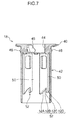
Fig. 7 is a cross-section taken from the side and illustrating a cap of a latch device according to the first exemplary embodiment of the present invention. -
Fig. 8 is a cross-section taken from the side and illustrating an attached state, to a vehicle body, of a latch device according to the first exemplary embodiment of the present invention. - Explanation follows regarding an exemplary embodiment of a latch device of the present invention, with reference to
Fig. 1 to Fig. 8 . - As illustrated in
Fig. 2 , alatch device 10 of the present exemplary embodiment is provided, for example, on a vehicle body of a car, to a vehicle bodyinner panel 14, serving as a second member, facing afuel lid 12, serving as a first member. Thefuel lid 12 is attached to theinner panel 14 by a hinge, not illustrated in the drawings, so as to be capable of swinging in opening or closing directions, such that thefuel lid 12 is retained in the closed position illustrated inFig. 2 , or is pushed out in a jutting out direction (the arrow A direction inFig. 2 ) that is the opening direction, by thelatch device 10. - As illustrated in
Fig. 1 , thelatch device 10 includes acase 16, arod 20, a jutting outportion 64 of therod 20 serving as a lock mechanism, acap 18, aslide cam 21, arotation cam 22, asleeve 120, agrommet 122, afirst spring 25, asecond spring 26 serving as a rod biasing member, and aboot 28. Note that the parts of thelatch device 10 are not limited to the parts listed above. Thefirst spring 25 and thesecond spring 26 are, as an example, configured by coiled springs, and the biasing force (load) of thefirst spring 25 is set smaller (lighter) than the biasing force (load) of thesecond spring 26. - As illustrated in
Fig. 3 , thecase 16 is formed in a tube shape. As illustrated inFig. 2 , anattachment hole 32 is formed in theinner panel 14 so as to pierce through the front and back faces thereof, and thecase 16 is fixed to theattachment hole 32. - As illustrated in
Fig. 3 , thecase 16 is formed in circular cylinder shape that is open at the upper face and formed with a bottom face. The external diameter of thecase 16 is set so as to be the internal diameter of theattachment hole 32 in theinner panel 14, or less. Aflange 34 is formed to an end portion on the open side of thecase 16 so as to extend in radial direction toward the outer side, and a ringshaped attachment portion 36 is formed at the upper side of theflange 34. Plural elastically deformableelastic claws 38 are formed at the lower side of theflange 34, jutting out in a radial pattern from the outer periphery of thecase 16. Theseelastic claws 38 are provided at a distance from the lower face of theflange 34 so as to maintain a separation thereto of the plate thickness of theinner panel 14. - As illustrated in
Fig. 2 , when thecase 16 is aligned with theattachment hole 32 and fitted therein, theelastic claws 38 are temporarily pushed in, and then elastically recover at the back face side of theinner panel 14, so as to sandwich theinner panel 14 between themselves and the lower face of theflange 34, thereby fixing thecase 16 to theattachment hole 32. - As illustrated in
Fig. 1 , thecap 18 is attached to the open upper face of thecase 16, and configures part of thecase 16. - As illustrated in
Fig. 3 , thecap 18 includes alid portion 40 that is slightly bigger than the open upper face of thecase 16, and acircular tube portion 42 that is one step narrower than, and extends in circular tube shape from, the lower face of thelid portion 40. - As illustrated in
Fig. 7 , a circular shaped throughhole 44 is formed piercing through an inner peripheral portion of thelid portion 40 of thecap 18, from top to bottom. Therod 20 is inserted into the throughhole 44.Projections 45, serving as a guide mechanism, are formed so as to jut out from inner peripheral portions of the throughhole 44. Thecircular tube portion 42 of thecap 18 is set with an outer circumference having the internal diameter of thecase 16 or smaller, and is inserted into thecase 16. Plural elasticallydeformable anchor claws 46 are formed jutting out in a radial pattern on the outer periphery of thecircular tube portion 42 of thecap 18, at locations adjacent to thelid portion 40. - As illustrated in
Fig. 3 , plural anchor holes 48 are formed in theattachment portion 36 of thecase 16, piercing through from the inside to the outside, such that theanchor claws 46 of thecap 18 fit into the anchor holes 48 of thecase 16. - Thus, by aligning the
circular tube portion 42 of thecap 18 with the open upper face of thecase 16 and fitting it therein, theanchor claws 46 are temporarily pushed in, and then theanchor claws 46 elastically fit into the anchor holes 48 so as to fix thecap 18 to thecase 16. - As illustrated in
Fig. 7 , recessedslide grooves 50 are formed in an inner peripheral face of thecircular tube portion 42 of thecap 18. Theslide grooves 50 retain theslide cam 21 so as be capable of sliding. A plurality of theslide grooves 50 are formed with blind upper end portions, and open lower end portions.Lock mechanisms 52 are provided at the lower side of theslide grooves 50, as recesses formed in the inner peripheral face of thecircular tube portion 42, such that thelock mechanisms 52 lock therotation cam 22 so as to render it non-rotatable. Thelock mechanisms 52 are formed in the spacing between adjacent of theslide grooves 50, and are formed as saw tooth shapes along the circumferential direction on the inner peripheral face of thecircular tube portion 42. - As illustrated in
Fig. 4 to Fig. 6 , with reference to one of theslide grooves 50, thelock mechanisms 52 each include: a firstsloping face portion 52A that slopes upwards (in the push-out direction of the rod) from theslide groove 50 on progression toward the front in a rotation direction of the rotation cam 22 (the direction of arrow B inFig. 4 to Fig. 6 ); alock portion 52B positioned at a slope upper end portion of the firstsloping face portion 52A, namely, positioned in front thereof in the rotation direction of therotation cam 22, with anengagement projection 56 of therotation cam 22, described later, fitted therein; a vertically ascendingvertical portion 52C descending downwards from thelock portion 52B; and an upward sloping secondsloping face portion 52D sloping upwards from a lower end portion of thevertical portion 52C, with an slope upper end portion that faces another of theslide grooves 50 positioned in front in the rotation direction of therotation cam 22. - A slope lower end portion of the first sloping face portion 54, namely at the rear thereof in the rotation direction of the
rotation cam 22, faces the oneslide groove 50. The slope angles are the same for the firstsloping face portions 52A and the secondsloping face portions 52D. - As illustrated in
Fig. 1 , therod 20 is retained inside thecase 16 so as to be capable of sliding, and juts out from inside thecase 16 to adopt an advanced position, so as to push out thefuel lid 12, as illustrated inFig. 2 . - As illustrated in
Fig. 3 , therod 20 is formed in a circular rod shape and includes: the circular plate shaped jutting outportion 64 that is positioned at an intermediate portion in the axial direction and juts outward in radial directions; an upper-side rod section 66 that is positioned at the upper side of the jutting outportion 64 and juts out from inside thecase 16 so as to push out thefuel lid 12; and a lower-side rod section 68 that is positioned at the lower side of the jutting outportion 64 and is inserted through thesecond spring 26. The jutting outportion 64 of therod 20 abuts a portion in the vicinity of the lower periphery of the throughhole 44 in thelid portion 40 of thecap 18, such that movement of therod 20 in the push-up direction is prevented. - The
slide cam 21 having the lower-side rod section 68 inserted therethrough is disposed at the lower side of the jutting outportion 64, i.e. at a position to the rear thereof in the jutting out direction of therod 20. Fixed-side cams 72 are formed on the lower face of theslide cam 21, and the fixed-side cams 72 mesh with movable-side cams 82 of therotation cam 22, described later. The fixed-side cams 72 are formed continuously around the circumferential direction on the lower face of theslide cam 21, so as to form obtuse angled saw tooth shapes. Plural slidingprojections 74 are formed at the outer periphery of theslide cam 21, jutting out in a radial pattern. - Due to the sliding
projections 74 of theslide cam 21 fitting into theslide grooves 50 of thecap 18, and the slidingprojections 74 ascending or descending along theslide grooves 50, theslide cam 21 is retained inside thecap 18 so as to be capable of sliding, but not capable of rotating. - As illustrated in
Fig. 3 , anengagement portion 67 is formed at an upper end of therod 20, this being a leading end portion of the upper-side rod section 66.Guide grooves 75, serving as a guide mechanism, are formed in a spiral shape at a length direction intermediate portion of the upper-side rod section 66 of therod 20. Therod 20 rotates about the axial direction thereof when therod 20 advances or retracts due to sliding movement between theguide grooves 75 and theprojections 45, serving as a guide mechanism of thecap 18. - As illustrated in
Fig. 2 , theengagement portion 67 of therod 20 has a bar shape extending in a direction orthogonal to the axial direction of therod 20. Thus, due to therod 20 rotating about the axial direction thereof when therod 20 advances or retracts, theengagement portion 67 rotates about the axial direction, so as to be engaged, or disengaged, in anengagement hole 69A of aretainer 69, serving as engaged portion, attached to the back face of thefuel lid 12. Theengagement hole 69A is an elongated hole formed in an upper wall portion of aretainer body 69B. - As illustrated in
Fig. 8 , theretainer body 69B of theretainer 69 is configured with a cap shape, so as to cover an upper portion of theboot 28. Anengagement portion 69C is provided so as to extend upward from an upper wall portion of theretainer body 69B, such that theretainer 69 can be attached to thefuel lid 12 by engaging theengagement portion 69C in anattachment hole 13 of thefuel lid 12. - Thus, as illustrated by the double-dotted dashed line in
Fig. 2 , when therod 20 is in the locked state, theengagement portion 67 of therod 20 is engaged with theengagement hole 69A of theretainer 69, so as to retain thefuel lid 12 in the closed state. - As illustrated in
Fig. 3 , a ring shapedannular groove 76 for attaching theboot 28 is formed in the vicinity of the upper end of the upper-side rod section 66 of therod 20. Aconstricted portion 80 is formed at a lower end portion of the lower-side rod section 68 of therod 20, narrowing so as to fit into a reduceddiameter portion 122B of thegrommet 122, described later. - The height of the
constricted portion 80 of therod 20 is set so as to be higher than the thickness in the up-down direction of the reduceddiameter portion 122B of thegrommet 122. This thereby achieves a configuration in which there is a clearance in the height direction of theconstricted portion 80 in a state in which the constrictedportion 80 is fitted into the reduceddiameter portion 122B. As a result, the reduceddiameter portion 122B of thegrommet 122 is able to ascend or descend up or down by the clearance amount to theconstricted portion 80 of therod 20. On the other hand, therod 20 is able to ascend or descend up or down with respect to thegrommet 122 by the clearance amount. - The amount of clearance is set according to the ascent or descent amount of the
rotation cam 22 referred to above as it ascends or descends between a first height position in which the movable-side cams 82 of therotation cam 22, described later, are meshed with the fixed-side cams 72 of theslide cam 21, and a second height position in which the movable-side cams 82 are disengaged from the fixed-side cams 72. - As illustrated in
Fig. 3 , thesleeve 120 includes a sleevemain body 120A, and aflange 120B, and thegrommet 122 includes a grommetmain body 122A, the reduceddiameter portion 122B, and slits 122C. - As illustrated in
Fig. 1 , the lower-side rod section 68 of therod 20 is inserted through thesleeve 120, and thesleeve 120 is positioned between therotation cam 22 and thesecond spring 26. The lower-side rod section 68 of therod 20 is inserted through thegrommet 122, and thegrommet 122 is positioned at the lower side of thesleeve 120. - As illustrated in
Fig. 3 , the sleevemain body 120A of thesleeve 120 and the grommetmain body 122A of thegrommet 122 are formed in tube shapes, and have the lower-side rod section 68 inserted therethrough. As illustrated inFig. 1 , theflange 120B of thesleeve 120 is positioned at an upper end portion of the sleevemain body 120A, abutting therotation cam 22, and extending in radial directions both outwards and inwards. - As illustrated in
Fig. 1 , the reduceddiameter portion 122B of thegrommet 122 is positioned at a lower end portion of the grommetmain body 122A at the opposite side to the upper end portion thereof, and juts out inward in radial directions. - Two pairs of the
slits 122C are formed in the diameter direction of the grommetmain body 122A, such that theslits 122C divide the lower end portion of the grommetmain body 122A into plural divisions. Theslits 122C are formed from the end face at the lower side of the grommetmain body 122A, upward to partway along the grommetmain body 122A. - As illustrated in
Fig. 1 , thefirst spring 25 is positioned between thegrommet 122 and thesleeve 120, is compressed between the grommetmain body 122A of thegrommet 122 and the inner peripheral portion of theflange 120B of thesleeve 120, and biases thesleeve 120 and thegrommet 122 in the direction away from each other. - As illustrated in
Fig. 1 , thesecond spring 26 is positioned between thecase 16 and thesleeve 120, is compressed between an outer peripheral portion of theflange portion 120B of thesleeve 120 and the bottom of thecase 16, and, through therotation cam 22 and theslide cam 21, biases therod 20 in the jutting out direction, pushing therod 20 out from inside thecase 16. - As illustrated in
Fig. 3 , a lock mechanism is configured by a rotation cam type mechanism provided with theslide cam 21 and therotation cam 22. The lock mechanism is positioned between thecase 16 and therod 20, so as to lock therod 20 in a position retracted in thecase 16 against the biasing force of thesecond spring 26. Therotation cam 22 is supported on the lower-side rod section 68 of therod 20 so as to be capable of rotating and also capable of sliding in the axial direction. Therotation cam 22 includes the movable-side cams 82 that mesh with the fixed-side cams 72 of theslide cam 21, and that are disengaged and imparted with a rotation force in one direction by sliding of therod 20. - The
rotation cam 22 is formed in a donut shape, and includes: acentral hole 86 that pierces through the center in the up-down direction and has the lower-side rod section 68 of therod 20 inserted therethrough; and the movable-side cams 82 that are formed on the upper face of therotation cam 22, that engage with the fixed-side cams 72 of theslide cam 21, and that are disengaged and imparted with biasing force in one direction by sliding of therod 20. The movable-side cams 82 are formed in complementary shapes to the fixed-side cams 72 of theslide cam 21, and are formed continuously around the circumferential direction on the upper face of therotation cam 22, so as to form obtuse angled saw tooth shapes. Theplural engagement projections 56 are formed in a radial pattern around the outer periphery of therotation cam 22. - As illustrated in
Fig. 4 to Fig. 6 , theengagement projections 56 of therotation cam 22 are each formed as a right trapezoid having an inclined face as the upper face in plan view, so as to fit into thelock portion 52B of therespective lock mechanism 52 of thecap 18. The inclined faces of the trapezoid shapedengagement projections 56 of therotation cam 22 each have an angle of inclination that matches the angles of inclination of the firstsloping face portion 52A and the secondsloping face portion 52D of therespective lock mechanism 52. - The left-right direction lateral width of the
engagement projections 56 of therotation cam 22 is set to the left-right direction groove width of theslide grooves 50 of thecap 18 or smaller, so as to be able to slide in theslide grooves 50. - As illustrated in
Fig. 3 , theboot 28 covers the upper-side rod section 66 that juts out from thecase 16, is extendable and retractable, and is provided between theengagement portion 67 of therod 20 and thecase 16. Theboot 28 is formed in a hollow concertina shape, with open upper face and lower face. As illustrated inFig. 1 , a ring shapedrecess 96 is formed in a ring shape jutting out in radial directions toward the inside on the inner peripheral face at the open lower face of theboot 28, and theflange 34 of thecase 16 fits into the ring shapedrecess 96. - A ring shaped ribbed
portion 97 is formed in ring shapes jutting out in radial directions toward the inside on the inner peripheral face at the open upper face of theboot 28. The ring shaped ribbedportion 97 of theboot 28 sandwiches a tube shapedcollar 100, serving as a slide resistance reduction member, provided at theboot 28 and a tube shapedseal 102, serving as a slide resistance reduction member, provided at therod 20 so as to fit into theannular groove 76 of therod 20, such that therod 20 rotates smoothly about the axial direction thereof with respect to theboot 28 during advancing and retracting of therod 20. - Thus, a configuration is achieved such that foreign objects can be prevented from adhering to the
guide grooves 75 and theprojections 45, due to the upper-side rod section 66 of therod 20 being covered by theboot 28 provided between theengagement portion 67 of therod 20 and thecase 16. Moreover, configuration is such that the slide resistance between therod 20 and theboot 28 is reduced, due to thecollar 100 and theseal 102 provided between therod 20 and theboot 28. - Explanation follows regarding operation and advantageous effects of the
latch device 10 of the present exemplary embodiment. - As illustrated in
Fig. 2 , in an assembled state, thelatch device 10 is fixed to theinner panel 14 by thecase 16 aligning with and fitting into theattachment hole 32 of theinner panel 14. In a closed state of thefuel lid 12, thelatch device 10 is locked while therod 20 is in a contracted lock state. - When the
fuel lid 12 in a closed state is pushed in, therod 20 of thelatch device 10 is pressed into thecase 16, and the locked state is released. As a result, therod 20 is jutted out from inside thecase 16 due to the recovery force from compression of thesecond spring 26, pushes thefuel lid 12 open, and releases engagement between theengagement portion 67 of therod 20 and theengagement hole 69A of theretainer 69. This thereby enables the pushedopen fuel lid 12 to be easily opened by hand. - To explain more specifically, in the contracted locked state of the
rod 20, as illustrated inFig. 6 , theengagement projections 56 of therotation cam 22 engage with thelock mechanisms 52 of thecap 18, and fit into thelock portions 52B. When, from this state, therod 20 is then pressed into thecase 16, therotation cam 22 descends together with theslide cam 21, pressed by the jutting outportion 64 of therod 20. Therefore, as illustrated inFig. 5 , theengagement projections 56 of therotation cam 22 are disengaged from thelock portions 52B of thecap 18. When this occurs, meshing between the fixed-side cams 72 of theslide cam 21 and the movable-side cams 82 of therotation cam 22 is disengaged, and therotation cam 22 rotates in the arrow B direction. Then, when the force pressing in therod 20 is released, therotation cam 22 is pushed up by recovery force from the compressedsecond spring 26. When this occurs, theengagement projections 56 of therotation cam 22 abut the secondsloping face portions 52D of thecap 18. Theengagement projections 56 accordingly ascend while make sliding contact with the secondsloping face portions 52D, and, as illustrated inFig. 4 , fit from the sloping face upper end portions of the secondsloping face portions 52D into theslide grooves 50. - As illustrated in
Fig. 4 , when theengagement projections 56 fit into theslide grooves 50, theengagement projections 56 are able to ascend along theslide grooves 50. The jutting outportion 64 of therod 20 is accordingly pressed up, through thegrommet 122, by recovery force from compression of the compressedsecond spring 26, and therod 20 extends so as to jut out from thecase 16. - On the other hand, when the opened
fuel lid 12 is closed by hand, theextended rod 20 of thelatch device 10 is pressed in toward thecase 16 against the biasing force of thesecond spring 26, and theengagement projections 56 of therotation cam 22 descend along theslide grooves 50. - Next, when the
rod 20 is pressed in further toward thecase 16 against the biasing force of thesecond spring 26, theengagement projections 56 of therotation cam 22 descend along theslide grooves 50, theengagement projections 56 move out past the open lower end of theslide grooves 50, and therotation cam 22 is then able to rotate. Thus, due to disengaging the meshing between the fixed-side cams 72 and the movable-side cams 82, therotation cam 22 rotates in the direction of arrow B inFig. 5 , and moves from the lower side of theslide grooves 50 toward the firstsloping face portions 52A of thelock mechanisms 52. - Next, when the force pressing in the
rod 20 is released, therotation cam 22 is pressed up by the recovery forces from compression of thefirst spring 25 and thesecond spring 26. When this occurs, theengagement projections 56 abut the firstsloping face portions 52A. Thereby, as illustrated inFig. 6 , theengagement projections 56 ascend while making sliding contact with the firstsloping face portions 52A, fit into thelock portions 52B, and return again to a locked state. - The
rod 20 rotates about the axial direction thereof during advancing or retracting of therod 20 due to theguide grooves 75 provided at therod 20 and theprojections 45 provided at thecap 18. In the locked state, theengagement portion 67 provided at the leading end portion of therod 20 engages with theengagement hole 69A of theretainer 69, serving as an engagement portion attached to the back face of thefuel lid 12, as illustrated by the double-dotted dashed line inFig. 2 , thereby enabling the fuellid fuel lid 12 to be retained in the closed state. - Thus, in the
latch device 10 of the present exemplary embodiment, thesecond spring 26 is elastically compressed between the inside of thecase 16 and thesleeve 120, and, through thesleeve 120, biases therod 20 in the jutting out direction. In the locked state as illustrated in Fig. 10, the biasing force of the second spring 26 (high load) neither acts directly on theengagement portion 67 and theguide grooves 75 of therod 20, nor on theprojections 45 of thecap 18. As a result, a drop in the durability of the latch device due to high load can be prevented. - Moreover, in the present exemplary embodiment, the lock mechanism is a rotation cam type lock mechanism configured as described above, with switching between locking and unlocking achieved by the rotation cam being operated by pressing the
rod 20 in. Switching between locking and unlocking is accordingly reliably achieved. - Moreover, in the present exemplary embodiment, foreign objects can be prevented from adhering to the
guide grooves 75 and theprojections 45, due to the upper-side rod section 66 of therod 20 being covered by theboot 28 provided between theengagement portion 67 and thecase 16. - Moreover, in the present exemplary embodiment, the slide resistance between the
rod 20 and theboot 28 is reduced, due to thecollar 100 and theseal 102 provided between therod 20 and theboot 28. The rotatability of therod 20 with respect to theboot 28 is improved as a result. - Although the present invention has been explained in detail for particular exemplary embodiments as described above, the present invention is not limited to the above exemplary embodiments, and it will be clear to a person of ordinary skill in the art that various other exemplary embodiments are possible within the range of the present invention. For example, the rod biasing member and lock mechanism are not limited to the configurations of the above exemplary embodiments.
- Moreover, although in each of the above exemplary embodiments, the
engagement portion 67 formed at the upper end of therod 20 is configured so as to engage with theengagement hole 69A of theretainer 69, serving as an engaged portion attached to the back face of thefuel lid 12, instead of this configuration, the engagement hole of the engaged portion may be configured by being formed on the back face of thefuel lid 12. The engaged portion is also not limited to an engagement hole, and another configuration may be adopted. - Moreover, although in each of the above exemplary embodiments, the
projections 45 serving as a guide mechanism are provided at thecap 18 of thecase 16, and the spiral shapedguide grooves 75 serving as the guide mechanism are formed to therod 20, instead of this configuration, a configuration may be adopted in which theguide grooves 75 serving as a guide mechanism are formed to thecap 18, and theprojections 45 serving as a guide mechanism are provided at therod 20. Moreover, the guide mechanism is not limited to theprojections 45 and the spiral shapedguide grooves 75, and another configuration may be adopted. - Moreover, although in each of the above exemplary embodiments, the tube shaped
collar 100, and the tube shapedseal 102 are used as slide resistance reduction members, the slide resistance reduction member is not limited to the tube shapedcollar 100 and the tube shapedseal 102, and another configuration may be adopted. - The
latch device 10 of the present invention in each of the above exemplary embodiments is attached to the vehicle bodyinner panel 14, serving as a second member, facing thefuel lid 12, serving as a first member. However, the latch device of the present invention may be attached to another second member other than a vehicle body inner panel, facing another first member other than a fuel lid. - The entire contents of the disclosure of
Japanese Patent Application No. 2014-003481 filed January 10, 2014 - All publications, patent applications and technical standards mentioned in the present specification are incorporated by reference in the present specification to the same extent as if the individual publication, patent application, or technical standard was specifically and individually indicated to be incorporated by reference.
Claims (5)
- A latch device, comprising:a tube shaped case that is fixed at a side of a second member that faces a first member;a rod that is retained inside the case so as to be capable of sliding, and that juts out from inside the case to adopt an advanced position pushing out the first member;a rod biasing member that is positioned between the case and the rod, and that is compressed under elastic deformation inside the case, so as to bias the rod in a jutting out direction pushing the rod out from inside the case;a lock mechanism including:a slide cam that moves together with the rod in the jutting out direction, anda rotation cam that is provided at a rear side of the slide cam in the jutting out direction and that is capable of relative rotation with respect to the slide cam about an axis of the rod,with the lock mechanism positioned between the case and the rod, and locking the rod in a retracted position in the case due to the rotation cam engaging with the slide cam and rotating due to the rod being pressed in against a biasing force of the rod biasing member;a guide mechanism that is provided between the rod and the case, and is for rotating the rod about an axial direction of the rod when the rod is advancing or retracting; andan engagement portion that is provided at the rod, that is capable of disengaging from an engaged portion of the first member due to the rod rotating about the axial direction thereof, and that engages with the engaged portion when the rod has been locked.
- The latch device of claim 1, wherein the lock mechanism further includes:a jutting out portion that is positioned partway along an axial direction of the rod and that juts out in a radial direction toward an outer side;a lower-side rod section positioned at the rear side in the jutting out direction with the jutting out portion as a boundary, so as to be capable of sliding in the axial direction, the lower-side rod section supporting the slide cam, and supporting the rotation cam at the rear side of the slide cam in the jutting out direction such that the rotation cam is capable of rotating and capable of sliding in the axial direction, and the rotation cam meshing with the slide cam, and disengaging and being imparted with a rotation force in one direction by sliding of the rod;a slide groove that is positioned at one of an outer peripheral face of the slide cam or an inner peripheral face of the case, and that extends along a slide direction of the rod,a slide projection that is positioned at another of the outer peripheral face of the slide cam or the inner peripheral face of the case, and that prevents rotation of the slide cam with respect to the case due to relative sliding of the slide projection inside the slide groove due to sliding of the slide cam;an engagement projection that juts out from one of an outer peripheral face of the rotation cam or the inner peripheral face of the case;a lock groove that is positioned at another of the outer peripheral face of the rotation cam or the inner peripheral face of the case, that includes a lock portion into which the engagement projection fits, the engagement projection that has been fitted into the lock portion being capable of disengaging from the lock portion by the rotation cam rotating due to the rotation cam disengaging from the slide cam;a sleeve that is supported at a rear side of the rotation cam in the jutting out direction by the lower-side rod section so as to be capable of rotating and capable of sliding in the axial direction, and that is capable of abutting the rotation cam; anda grommet that is disposed at a rear side of the sleeve in the jutting out direction, that is inserted at the lower-side rod section, and that limits movement of the rod in the slide direction.
- The latch device of claim 1 or claim 2, further comprising a boot that is provided between the engagement portion and the case, and that covers the rod.
- The latch device of claim 3, further comprising a slide resistance reduction member that is provided between the rod and the boot to reduce slide resistance between the rod and the boot.
- The latch device of any one of claim 1 to claim 4, wherein the second member is a vehicle body, and the first member is a fuel lid attached to the vehicle body so as to be capable of rotating in opening and closing directions.
Applications Claiming Priority (2)
| Application Number | Priority Date | Filing Date | Title |
|---|---|---|---|
| JP2014003481A JP6309276B2 (en) | 2014-01-10 | 2014-01-10 | Latch device |
| PCT/JP2015/050555 WO2015105193A1 (en) | 2014-01-10 | 2015-01-09 | Latch device |
Publications (3)
| Publication Number | Publication Date |
|---|---|
| EP3093421A1 true EP3093421A1 (en) | 2016-11-16 |
| EP3093421A4 EP3093421A4 (en) | 2017-11-15 |
| EP3093421B1 EP3093421B1 (en) | 2018-11-14 |
Family
ID=53524014
Family Applications (1)
| Application Number | Title | Priority Date | Filing Date |
|---|---|---|---|
| EP15735550.4A Active EP3093421B1 (en) | 2014-01-10 | 2015-01-09 | Latch device |
Country Status (6)
| Country | Link |
|---|---|
| US (1) | US11214993B2 (en) |
| EP (1) | EP3093421B1 (en) |
| JP (1) | JP6309276B2 (en) |
| KR (1) | KR101851088B1 (en) |
| CN (1) | CN105899745B (en) |
| WO (1) | WO2015105193A1 (en) |
Families Citing this family (23)
| Publication number | Priority date | Publication date | Assignee | Title |
|---|---|---|---|---|
| US20170074010A1 (en) * | 2015-09-16 | 2017-03-16 | Big Toe Innovations Inc. | Push, pull and rotate deadbolt and passage set and helical gear mechanism therein |
| ITUB20159487A1 (en) * | 2015-12-29 | 2017-06-29 | Cebi Italy Spa | FUEL TANK FUEL TANK OF VEHICLE WITH SEALING CLOSING DEVICE. |
| KR101776461B1 (en) * | 2016-02-24 | 2017-09-07 | 현대자동차주식회사 | Fuel door opener |
| CN105946571B (en) * | 2016-05-04 | 2018-11-06 | 杰必机电配件(上海)有限公司 | Cover board control device and automobile |
| JP6670179B2 (en) | 2016-05-31 | 2020-03-18 | 株式会社ハイレックスコーポレーション | Reciprocating device |
| US9856681B1 (en) * | 2016-06-17 | 2018-01-02 | Nifco America Corp. | Push lifter |
| EP3529432B1 (en) * | 2016-10-24 | 2021-01-13 | Kvadrat Soft Cells A/S | Fastening device and system of fastening panels to a structure |
| CN106985660B (en) * | 2017-04-10 | 2019-08-20 | 上海蔚来汽车有限公司 | Guide part, energy filling mouth assembly and the vehicle including it |
| DE102017116230A1 (en) * | 2017-07-19 | 2019-01-24 | Cebi Italy S.P. A. Ancona | Locking device for tank or loading troughs and tank or loading trough |
| JP2019023406A (en) * | 2017-07-24 | 2019-02-14 | 株式会社Lixil | Lock mechanism |
| KR101824411B1 (en) | 2017-11-29 | 2018-02-01 | 쌍용자동차 주식회사 | Door locking support of the automobile fuel filler door housing assembly |
| JP6941552B2 (en) * | 2017-12-15 | 2021-09-29 | 株式会社ユーシン | Lid switchgear |
| JP6941551B2 (en) * | 2017-12-15 | 2021-09-29 | 株式会社ユーシン | Lid switchgear |
| JP6944361B2 (en) * | 2017-12-15 | 2021-10-06 | 株式会社ユーシン | Push-push mechanism and lid switchgear equipped with it |
| CN109930926B (en) * | 2017-12-15 | 2022-02-25 | 株式会社有信 | Lid opening and closing device |
| JP6784714B2 (en) * | 2018-02-28 | 2020-11-11 | 株式会社ニフコ | In-vehicle push lifter |
| DE102020103285B4 (en) * | 2019-02-26 | 2024-11-14 | Illinois Tool Works Inc. | ACTUATOR FOR OPENING AND CLOSING A COVER IN OR ON A VEHICLE AS NEEDED AND COVER WITH SUCH ACTUATOR |
| JP7100267B2 (en) | 2019-08-26 | 2022-07-13 | 株式会社アンセイ | Closure opening and closing device for vehicles |
| JP7037081B2 (en) * | 2019-09-06 | 2022-03-16 | 株式会社アンセイ | Closure opening and closing device for vehicles |
| DE102019126481B3 (en) * | 2019-10-01 | 2021-02-11 | Dr. Ing. H.C. F. Porsche Aktiengesellschaft | Locking device for locking a loading flap of an electrically operated motor vehicle and electrically operated motor vehicle comprising such a locking device |
| JP7096502B2 (en) | 2019-11-25 | 2022-07-06 | 株式会社アンセイ | Reciprocating device |
| WO2021117594A1 (en) * | 2019-12-10 | 2021-06-17 | 株式会社パイオラックス | Unlocking device |
| CN116018444B (en) * | 2020-09-25 | 2025-08-29 | 株式会社海莱客思 | Forward and backward movement device |
Family Cites Families (15)
| Publication number | Priority date | Publication date | Assignee | Title |
|---|---|---|---|---|
| JPH057407Y2 (en) * | 1986-08-04 | 1993-02-24 | ||
| JPH0631080Y2 (en) * | 1988-10-31 | 1994-08-22 | 株式会社ニフコ | Latch device |
| JPH057407A (en) | 1991-06-29 | 1993-01-19 | Yanmar Agricult Equip Co Ltd | Seedling table safety device in rice transplanter |
| JP2526206Y2 (en) | 1991-07-17 | 1997-02-19 | 株式会社イナックス | Hollow extruded plate |
| JP3515212B2 (en) * | 1995-05-18 | 2004-04-05 | シロキ工業株式会社 | Key device |
| JP4164329B2 (en) * | 2002-10-17 | 2008-10-15 | 株式会社ニフコ | Latch device |
| JP5004268B2 (en) * | 2006-04-25 | 2012-08-22 | 株式会社ニフコ | Pushing device |
| ITMI20071828A1 (en) * | 2007-09-21 | 2009-03-22 | Salice Arturo Spa | ATTACHMENT AND RELEASING RELEASE DEVICE OF A MOVABLE PART AT A FIXED-DAY SECTION MOBILE |
| JP5118102B2 (en) * | 2009-06-25 | 2013-01-16 | 株式会社ニフコ | Pushing device |
| JP2011256528A (en) * | 2010-06-04 | 2011-12-22 | Nifco Inc | Fuel lid opening/closing device |
| JP5690175B2 (en) * | 2011-03-02 | 2015-03-25 | 株式会社ニフコ | Pushing device |
| DE102011116067A1 (en) * | 2011-07-22 | 2013-01-24 | Kiekert Ag | Tank flap lock with reduced number of components |
| KR101260217B1 (en) | 2013-01-30 | 2013-05-06 | (주) 코스텍 | A door opening and closing device for a vehicle fuel cap |
| JP6346444B2 (en) * | 2014-01-10 | 2018-06-20 | 株式会社ニフコ | Pushing device |
| JP6359982B2 (en) * | 2015-02-02 | 2018-07-18 | 株式会社ハイレックスコーポレーション | Advance / Retreat Device |
-
2014
- 2014-01-10 JP JP2014003481A patent/JP6309276B2/en active Active
-
2015
- 2015-01-09 US US15/110,330 patent/US11214993B2/en active Active
- 2015-01-09 KR KR1020167018553A patent/KR101851088B1/en active Active
- 2015-01-09 WO PCT/JP2015/050555 patent/WO2015105193A1/en not_active Ceased
- 2015-01-09 EP EP15735550.4A patent/EP3093421B1/en active Active
- 2015-01-09 CN CN201580004132.4A patent/CN105899745B/en active Active
Also Published As
| Publication number | Publication date |
|---|---|
| US20160348408A1 (en) | 2016-12-01 |
| EP3093421A4 (en) | 2017-11-15 |
| JP2015132085A (en) | 2015-07-23 |
| EP3093421B1 (en) | 2018-11-14 |
| CN105899745A (en) | 2016-08-24 |
| WO2015105193A1 (en) | 2015-07-16 |
| JP6309276B2 (en) | 2018-04-11 |
| KR20160097322A (en) | 2016-08-17 |
| CN105899745B (en) | 2017-10-17 |
| KR101851088B1 (en) | 2018-04-20 |
| US11214993B2 (en) | 2022-01-04 |
Similar Documents
| Publication | Publication Date | Title |
|---|---|---|
| EP3093421B1 (en) | Latch device | |
| US9982467B2 (en) | Push-up device | |
| EP2682295B1 (en) | Push-out device | |
| US8485585B2 (en) | Push-up device | |
| KR101263609B1 (en) | Fuel lid opening/closing device | |
| US8769779B2 (en) | Inertia locking hidden pushpin | |
| CA3070873C (en) | Combination lock | |
| US12352097B2 (en) | Stopper device | |
| US9856681B1 (en) | Push lifter | |
| CN105317988A (en) | Shift Knob Structure |
Legal Events
| Date | Code | Title | Description |
|---|---|---|---|
| PUAI | Public reference made under article 153(3) epc to a published international application that has entered the european phase |
Free format text: ORIGINAL CODE: 0009012 |
|
| 17P | Request for examination filed |
Effective date: 20160715 |
|
| AK | Designated contracting states |
Kind code of ref document: A1 Designated state(s): AL AT BE BG CH CY CZ DE DK EE ES FI FR GB GR HR HU IE IS IT LI LT LU LV MC MK MT NL NO PL PT RO RS SE SI SK SM TR |
|
| AX | Request for extension of the european patent |
Extension state: BA ME |
|
| DAX | Request for extension of the european patent (deleted) | ||
| A4 | Supplementary search report drawn up and despatched |
Effective date: 20171018 |
|
| RIC1 | Information provided on ipc code assigned before grant |
Ipc: B60K 15/05 20060101ALI20171012BHEP Ipc: E05C 19/02 20060101AFI20171012BHEP Ipc: E05B 83/34 20140101ALI20171012BHEP |
|
| GRAP | Despatch of communication of intention to grant a patent |
Free format text: ORIGINAL CODE: EPIDOSNIGR1 |
|
| STAA | Information on the status of an ep patent application or granted ep patent |
Free format text: STATUS: GRANT OF PATENT IS INTENDED |
|
| INTG | Intention to grant announced |
Effective date: 20180614 |
|
| GRAS | Grant fee paid |
Free format text: ORIGINAL CODE: EPIDOSNIGR3 |
|
| GRAA | (expected) grant |
Free format text: ORIGINAL CODE: 0009210 |
|
| STAA | Information on the status of an ep patent application or granted ep patent |
Free format text: STATUS: THE PATENT HAS BEEN GRANTED |
|
| AK | Designated contracting states |
Kind code of ref document: B1 Designated state(s): AL AT BE BG CH CY CZ DE DK EE ES FI FR GB GR HR HU IE IS IT LI LT LU LV MC MK MT NL NO PL PT RO RS SE SI SK SM TR |
|
| REG | Reference to a national code |
Ref country code: CH Ref legal event code: EP Ref country code: AT Ref legal event code: REF Ref document number: 1065016 Country of ref document: AT Kind code of ref document: T Effective date: 20181115 |
|
| REG | Reference to a national code |
Ref country code: DE Ref legal event code: R096 Ref document number: 602015019874 Country of ref document: DE |
|
| REG | Reference to a national code |
Ref country code: IE Ref legal event code: FG4D |
|
| REG | Reference to a national code |
Ref country code: NL Ref legal event code: MP Effective date: 20181114 |
|
| REG | Reference to a national code |
Ref country code: LT Ref legal event code: MG4D |
|
| REG | Reference to a national code |
Ref country code: AT Ref legal event code: MK05 Ref document number: 1065016 Country of ref document: AT Kind code of ref document: T Effective date: 20181114 |
|
| PG25 | Lapsed in a contracting state [announced via postgrant information from national office to epo] |
Ref country code: LV Free format text: LAPSE BECAUSE OF FAILURE TO SUBMIT A TRANSLATION OF THE DESCRIPTION OR TO PAY THE FEE WITHIN THE PRESCRIBED TIME-LIMIT Effective date: 20181114 Ref country code: ES Free format text: LAPSE BECAUSE OF FAILURE TO SUBMIT A TRANSLATION OF THE DESCRIPTION OR TO PAY THE FEE WITHIN THE PRESCRIBED TIME-LIMIT Effective date: 20181114 Ref country code: LT Free format text: LAPSE BECAUSE OF FAILURE TO SUBMIT A TRANSLATION OF THE DESCRIPTION OR TO PAY THE FEE WITHIN THE PRESCRIBED TIME-LIMIT Effective date: 20181114 Ref country code: NO Free format text: LAPSE BECAUSE OF FAILURE TO SUBMIT A TRANSLATION OF THE DESCRIPTION OR TO PAY THE FEE WITHIN THE PRESCRIBED TIME-LIMIT Effective date: 20190214 Ref country code: AT Free format text: LAPSE BECAUSE OF FAILURE TO SUBMIT A TRANSLATION OF THE DESCRIPTION OR TO PAY THE FEE WITHIN THE PRESCRIBED TIME-LIMIT Effective date: 20181114 Ref country code: IS Free format text: LAPSE BECAUSE OF FAILURE TO SUBMIT A TRANSLATION OF THE DESCRIPTION OR TO PAY THE FEE WITHIN THE PRESCRIBED TIME-LIMIT Effective date: 20190314 Ref country code: FI Free format text: LAPSE BECAUSE OF FAILURE TO SUBMIT A TRANSLATION OF THE DESCRIPTION OR TO PAY THE FEE WITHIN THE PRESCRIBED TIME-LIMIT Effective date: 20181114 Ref country code: BG Free format text: LAPSE BECAUSE OF FAILURE TO SUBMIT A TRANSLATION OF THE DESCRIPTION OR TO PAY THE FEE WITHIN THE PRESCRIBED TIME-LIMIT Effective date: 20190214 Ref country code: HR Free format text: LAPSE BECAUSE OF FAILURE TO SUBMIT A TRANSLATION OF THE DESCRIPTION OR TO PAY THE FEE WITHIN THE PRESCRIBED TIME-LIMIT Effective date: 20181114 |
|
| PG25 | Lapsed in a contracting state [announced via postgrant information from national office to epo] |
Ref country code: GR Free format text: LAPSE BECAUSE OF FAILURE TO SUBMIT A TRANSLATION OF THE DESCRIPTION OR TO PAY THE FEE WITHIN THE PRESCRIBED TIME-LIMIT Effective date: 20190215 Ref country code: NL Free format text: LAPSE BECAUSE OF FAILURE TO SUBMIT A TRANSLATION OF THE DESCRIPTION OR TO PAY THE FEE WITHIN THE PRESCRIBED TIME-LIMIT Effective date: 20181114 Ref country code: SE Free format text: LAPSE BECAUSE OF FAILURE TO SUBMIT A TRANSLATION OF THE DESCRIPTION OR TO PAY THE FEE WITHIN THE PRESCRIBED TIME-LIMIT Effective date: 20181114 Ref country code: AL Free format text: LAPSE BECAUSE OF FAILURE TO SUBMIT A TRANSLATION OF THE DESCRIPTION OR TO PAY THE FEE WITHIN THE PRESCRIBED TIME-LIMIT Effective date: 20181114 Ref country code: PT Free format text: LAPSE BECAUSE OF FAILURE TO SUBMIT A TRANSLATION OF THE DESCRIPTION OR TO PAY THE FEE WITHIN THE PRESCRIBED TIME-LIMIT Effective date: 20190314 Ref country code: RS Free format text: LAPSE BECAUSE OF FAILURE TO SUBMIT A TRANSLATION OF THE DESCRIPTION OR TO PAY THE FEE WITHIN THE PRESCRIBED TIME-LIMIT Effective date: 20181114 |
|
| PG25 | Lapsed in a contracting state [announced via postgrant information from national office to epo] |
Ref country code: DK Free format text: LAPSE BECAUSE OF FAILURE TO SUBMIT A TRANSLATION OF THE DESCRIPTION OR TO PAY THE FEE WITHIN THE PRESCRIBED TIME-LIMIT Effective date: 20181114 Ref country code: PL Free format text: LAPSE BECAUSE OF FAILURE TO SUBMIT A TRANSLATION OF THE DESCRIPTION OR TO PAY THE FEE WITHIN THE PRESCRIBED TIME-LIMIT Effective date: 20181114 Ref country code: CZ Free format text: LAPSE BECAUSE OF FAILURE TO SUBMIT A TRANSLATION OF THE DESCRIPTION OR TO PAY THE FEE WITHIN THE PRESCRIBED TIME-LIMIT Effective date: 20181114 Ref country code: IT Free format text: LAPSE BECAUSE OF FAILURE TO SUBMIT A TRANSLATION OF THE DESCRIPTION OR TO PAY THE FEE WITHIN THE PRESCRIBED TIME-LIMIT Effective date: 20181114 |
|
| REG | Reference to a national code |
Ref country code: DE Ref legal event code: R097 Ref document number: 602015019874 Country of ref document: DE |
|
| PG25 | Lapsed in a contracting state [announced via postgrant information from national office to epo] |
Ref country code: RO Free format text: LAPSE BECAUSE OF FAILURE TO SUBMIT A TRANSLATION OF THE DESCRIPTION OR TO PAY THE FEE WITHIN THE PRESCRIBED TIME-LIMIT Effective date: 20181114 Ref country code: SM Free format text: LAPSE BECAUSE OF FAILURE TO SUBMIT A TRANSLATION OF THE DESCRIPTION OR TO PAY THE FEE WITHIN THE PRESCRIBED TIME-LIMIT Effective date: 20181114 Ref country code: EE Free format text: LAPSE BECAUSE OF FAILURE TO SUBMIT A TRANSLATION OF THE DESCRIPTION OR TO PAY THE FEE WITHIN THE PRESCRIBED TIME-LIMIT Effective date: 20181114 Ref country code: MC Free format text: LAPSE BECAUSE OF FAILURE TO SUBMIT A TRANSLATION OF THE DESCRIPTION OR TO PAY THE FEE WITHIN THE PRESCRIBED TIME-LIMIT Effective date: 20181114 Ref country code: SK Free format text: LAPSE BECAUSE OF FAILURE TO SUBMIT A TRANSLATION OF THE DESCRIPTION OR TO PAY THE FEE WITHIN THE PRESCRIBED TIME-LIMIT Effective date: 20181114 |
|
| REG | Reference to a national code |
Ref country code: CH Ref legal event code: PL |
|
| PLBE | No opposition filed within time limit |
Free format text: ORIGINAL CODE: 0009261 |
|
| STAA | Information on the status of an ep patent application or granted ep patent |
Free format text: STATUS: NO OPPOSITION FILED WITHIN TIME LIMIT |
|
| PG25 | Lapsed in a contracting state [announced via postgrant information from national office to epo] |
Ref country code: LU Free format text: LAPSE BECAUSE OF NON-PAYMENT OF DUE FEES Effective date: 20190109 |
|
| REG | Reference to a national code |
Ref country code: BE Ref legal event code: MM Effective date: 20190131 |
|
| 26N | No opposition filed |
Effective date: 20190815 |
|
| GBPC | Gb: european patent ceased through non-payment of renewal fee |
Effective date: 20190214 |
|
| REG | Reference to a national code |
Ref country code: IE Ref legal event code: MM4A |
|
| PG25 | Lapsed in a contracting state [announced via postgrant information from national office to epo] |
Ref country code: FR Free format text: LAPSE BECAUSE OF NON-PAYMENT OF DUE FEES Effective date: 20190114 Ref country code: SI Free format text: LAPSE BECAUSE OF FAILURE TO SUBMIT A TRANSLATION OF THE DESCRIPTION OR TO PAY THE FEE WITHIN THE PRESCRIBED TIME-LIMIT Effective date: 20181114 |
|
| PG25 | Lapsed in a contracting state [announced via postgrant information from national office to epo] |
Ref country code: BE Free format text: LAPSE BECAUSE OF NON-PAYMENT OF DUE FEES Effective date: 20190131 |
|
| PG25 | Lapsed in a contracting state [announced via postgrant information from national office to epo] |
Ref country code: LI Free format text: LAPSE BECAUSE OF NON-PAYMENT OF DUE FEES Effective date: 20190131 Ref country code: CH Free format text: LAPSE BECAUSE OF NON-PAYMENT OF DUE FEES Effective date: 20190131 |
|
| PG25 | Lapsed in a contracting state [announced via postgrant information from national office to epo] |
Ref country code: GB Free format text: LAPSE BECAUSE OF NON-PAYMENT OF DUE FEES Effective date: 20190214 Ref country code: IE Free format text: LAPSE BECAUSE OF NON-PAYMENT OF DUE FEES Effective date: 20190109 |
|
| PG25 | Lapsed in a contracting state [announced via postgrant information from national office to epo] |
Ref country code: TR Free format text: LAPSE BECAUSE OF FAILURE TO SUBMIT A TRANSLATION OF THE DESCRIPTION OR TO PAY THE FEE WITHIN THE PRESCRIBED TIME-LIMIT Effective date: 20181114 |
|
| PG25 | Lapsed in a contracting state [announced via postgrant information from national office to epo] |
Ref country code: MT Free format text: LAPSE BECAUSE OF NON-PAYMENT OF DUE FEES Effective date: 20190109 |
|
| PG25 | Lapsed in a contracting state [announced via postgrant information from national office to epo] |
Ref country code: CY Free format text: LAPSE BECAUSE OF FAILURE TO SUBMIT A TRANSLATION OF THE DESCRIPTION OR TO PAY THE FEE WITHIN THE PRESCRIBED TIME-LIMIT Effective date: 20181114 |
|
| PG25 | Lapsed in a contracting state [announced via postgrant information from national office to epo] |
Ref country code: HU Free format text: LAPSE BECAUSE OF FAILURE TO SUBMIT A TRANSLATION OF THE DESCRIPTION OR TO PAY THE FEE WITHIN THE PRESCRIBED TIME-LIMIT; INVALID AB INITIO Effective date: 20150109 |
|
| PG25 | Lapsed in a contracting state [announced via postgrant information from national office to epo] |
Ref country code: MK Free format text: LAPSE BECAUSE OF FAILURE TO SUBMIT A TRANSLATION OF THE DESCRIPTION OR TO PAY THE FEE WITHIN THE PRESCRIBED TIME-LIMIT Effective date: 20181114 |
|
| PGFP | Annual fee paid to national office [announced via postgrant information from national office to epo] |
Ref country code: DE Payment date: 20251203 Year of fee payment: 12 |