EP3093259A2 - Pneumatic adjusting system - Google Patents
Pneumatic adjusting system Download PDFInfo
- Publication number
- EP3093259A2 EP3093259A2 EP16169204.1A EP16169204A EP3093259A2 EP 3093259 A2 EP3093259 A2 EP 3093259A2 EP 16169204 A EP16169204 A EP 16169204A EP 3093259 A2 EP3093259 A2 EP 3093259A2
- Authority
- EP
- European Patent Office
- Prior art keywords
- piston
- adjustment
- adjusting
- unit
- air chamber
- Prior art date
- Legal status (The legal status is an assumption and is not a legal conclusion. Google has not performed a legal analysis and makes no representation as to the accuracy of the status listed.)
- Granted
Links
- 238000006243 chemical reaction Methods 0.000 description 4
- 239000002184 metal Substances 0.000 description 4
- 230000001960 triggered effect Effects 0.000 description 2
- 206010019196 Head injury Diseases 0.000 description 1
- 238000000071 blow moulding Methods 0.000 description 1
- 238000007689 inspection Methods 0.000 description 1
Images


Classifications
-
- B—PERFORMING OPERATIONS; TRANSPORTING
- B65—CONVEYING; PACKING; STORING; HANDLING THIN OR FILAMENTARY MATERIAL
- B65G—TRANSPORT OR STORAGE DEVICES, e.g. CONVEYORS FOR LOADING OR TIPPING, SHOP CONVEYOR SYSTEMS OR PNEUMATIC TUBE CONVEYORS
- B65G21/00—Supporting or protective framework or housings for endless load-carriers or traction elements of belt or chain conveyors
- B65G21/20—Means incorporated in, or attached to, framework or housings for guiding load-carriers, traction elements or loads supported on moving surfaces
-
- B—PERFORMING OPERATIONS; TRANSPORTING
- B65—CONVEYING; PACKING; STORING; HANDLING THIN OR FILAMENTARY MATERIAL
- B65G—TRANSPORT OR STORAGE DEVICES, e.g. CONVEYORS FOR LOADING OR TIPPING, SHOP CONVEYOR SYSTEMS OR PNEUMATIC TUBE CONVEYORS
- B65G47/00—Article or material-handling devices associated with conveyors; Methods employing such devices
- B65G47/22—Devices influencing the relative position or the attitude of articles during transit by conveyors
- B65G47/24—Devices influencing the relative position or the attitude of articles during transit by conveyors orientating the articles
-
- B—PERFORMING OPERATIONS; TRANSPORTING
- B29—WORKING OF PLASTICS; WORKING OF SUBSTANCES IN A PLASTIC STATE IN GENERAL
- B29C—SHAPING OR JOINING OF PLASTICS; SHAPING OF MATERIAL IN A PLASTIC STATE, NOT OTHERWISE PROVIDED FOR; AFTER-TREATMENT OF THE SHAPED PRODUCTS, e.g. REPAIRING
- B29C49/00—Blow-moulding, i.e. blowing a preform or parison to a desired shape within a mould; Apparatus therefor
- B29C49/42—Component parts, details or accessories; Auxiliary operations
- B29C49/4205—Handling means, e.g. transfer, loading or discharging means
-
- B—PERFORMING OPERATIONS; TRANSPORTING
- B65—CONVEYING; PACKING; STORING; HANDLING THIN OR FILAMENTARY MATERIAL
- B65G—TRANSPORT OR STORAGE DEVICES, e.g. CONVEYORS FOR LOADING OR TIPPING, SHOP CONVEYOR SYSTEMS OR PNEUMATIC TUBE CONVEYORS
- B65G21/00—Supporting or protective framework or housings for endless load-carriers or traction elements of belt or chain conveyors
- B65G21/20—Means incorporated in, or attached to, framework or housings for guiding load-carriers, traction elements or loads supported on moving surfaces
- B65G21/2045—Mechanical means for guiding or retaining the load on the load-carrying surface
- B65G21/2063—Mechanical means for guiding or retaining the load on the load-carrying surface comprising elements not movable in the direction of load-transport
- B65G21/2072—Laterial guidance means
-
- B—PERFORMING OPERATIONS; TRANSPORTING
- B65—CONVEYING; PACKING; STORING; HANDLING THIN OR FILAMENTARY MATERIAL
- B65G—TRANSPORT OR STORAGE DEVICES, e.g. CONVEYORS FOR LOADING OR TIPPING, SHOP CONVEYOR SYSTEMS OR PNEUMATIC TUBE CONVEYORS
- B65G21/00—Supporting or protective framework or housings for endless load-carriers or traction elements of belt or chain conveyors
- B65G21/20—Means incorporated in, or attached to, framework or housings for guiding load-carriers, traction elements or loads supported on moving surfaces
- B65G21/2045—Mechanical means for guiding or retaining the load on the load-carrying surface
- B65G21/2063—Mechanical means for guiding or retaining the load on the load-carrying surface comprising elements not movable in the direction of load-transport
- B65G21/209—Mechanical means for guiding or retaining the load on the load-carrying surface comprising elements not movable in the direction of load-transport for augmenting or creating a pression force between the load and the load-carrying surface
-
- B—PERFORMING OPERATIONS; TRANSPORTING
- B65—CONVEYING; PACKING; STORING; HANDLING THIN OR FILAMENTARY MATERIAL
- B65G—TRANSPORT OR STORAGE DEVICES, e.g. CONVEYORS FOR LOADING OR TIPPING, SHOP CONVEYOR SYSTEMS OR PNEUMATIC TUBE CONVEYORS
- B65G51/00—Conveying articles through pipes or tubes by fluid flow or pressure; Conveying articles over a flat surface, e.g. the base of a trough, by jets located in the surface
- B65G51/02—Directly conveying the articles, e.g. slips, sheets, stockings, containers or workpieces, by flowing gases
- B65G51/03—Directly conveying the articles, e.g. slips, sheets, stockings, containers or workpieces, by flowing gases over a flat surface or in troughs
- B65G51/035—Directly conveying the articles, e.g. slips, sheets, stockings, containers or workpieces, by flowing gases over a flat surface or in troughs for suspended articles, e.g. bottles
-
- B—PERFORMING OPERATIONS; TRANSPORTING
- B29—WORKING OF PLASTICS; WORKING OF SUBSTANCES IN A PLASTIC STATE IN GENERAL
- B29K—INDEXING SCHEME ASSOCIATED WITH SUBCLASSES B29B, B29C OR B29D, RELATING TO MOULDING MATERIALS OR TO MATERIALS FOR MOULDS, REINFORCEMENTS, FILLERS OR PREFORMED PARTS, e.g. INSERTS
- B29K2105/00—Condition, form or state of moulded material or of the material to be shaped
- B29K2105/25—Solid
- B29K2105/253—Preform
- B29K2105/258—Tubular
-
- B—PERFORMING OPERATIONS; TRANSPORTING
- B29—WORKING OF PLASTICS; WORKING OF SUBSTANCES IN A PLASTIC STATE IN GENERAL
- B29L—INDEXING SCHEME ASSOCIATED WITH SUBCLASS B29C, RELATING TO PARTICULAR ARTICLES
- B29L2031/00—Other particular articles
- B29L2031/712—Containers; Packaging elements or accessories, Packages
-
- B—PERFORMING OPERATIONS; TRANSPORTING
- B65—CONVEYING; PACKING; STORING; HANDLING THIN OR FILAMENTARY MATERIAL
- B65G—TRANSPORT OR STORAGE DEVICES, e.g. CONVEYORS FOR LOADING OR TIPPING, SHOP CONVEYOR SYSTEMS OR PNEUMATIC TUBE CONVEYORS
- B65G2201/00—Indexing codes relating to handling devices, e.g. conveyors, characterised by the type of product or load being conveyed or handled
- B65G2201/02—Articles
- B65G2201/0235—Containers
- B65G2201/0244—Bottles
- B65G2201/0247—Suspended bottles
-
- F—MECHANICAL ENGINEERING; LIGHTING; HEATING; WEAPONS; BLASTING
- F15—FLUID-PRESSURE ACTUATORS; HYDRAULICS OR PNEUMATICS IN GENERAL
- F15B—SYSTEMS ACTING BY MEANS OF FLUIDS IN GENERAL; FLUID-PRESSURE ACTUATORS, e.g. SERVOMOTORS; DETAILS OF FLUID-PRESSURE SYSTEMS, NOT OTHERWISE PROVIDED FOR
- F15B15/00—Fluid-actuated devices for displacing a member from one position to another; Gearing associated therewith
- F15B15/20—Other details, e.g. assembly with regulating devices
- F15B15/24—Other details, e.g. assembly with regulating devices for restricting the stroke
Definitions
- the invention relates to a pneumatic adjustment system for adjusting the mutual distance of at least two guide devices, such as guide rails for the removal or further transport of about preforms for plastic containers, from a roller sorter for further processing in, for example, a downstream inspection and ejector unit.
- an adjustment system in particular for adjusting the mutual spacing of at least two guide devices for transporting preforms for plastic containers, wherein the at least two guide devices are each connected to an adjustment unit, wherein the adjustment unit comprises at least one piston-like element each, which is movable in a pneumatic manner between a first stop and a second stop within the setting back and forth.
- the guide devices are preferably once in the form of two mirror-symmetrically opposite Z-profiles formed (ie for supporting the collar of the preforms on the top and possibly for slipping of the preforms along the transport path) and more preferably in the form of two mirror-symmetrically opposite L. Profiles attached thereto, kinked sheets (ie for lateral guidance of the cylindrical preform body) is formed.
- WH 38 mm "wide neck”
- the adjustment unit each defines an air chamber, in which at least parts of the piston-like element are movably mounted.
- the piston-like element is preferably designed in the form of a piston rod, which has a shaft part and a piston part. Further preferably divided in particular the Piston part of the piston rod, the air chamber in a first air chamber side (lying outward) and a second air chamber side (lying inwards). The piston part abuts the bottom and the top of the air chamber and, together with the shaft part, can be moved horizontally in the air chamber to move it back and forth.
- the first and the second air chamber side are each connected to a pneumatic supply device, so that each of the two air chamber sides can be acted upon via corresponding lines or channels separately with compressed air, so that a stroke of the piston, to the outside or to the inside, can be performed.
- the pneumatic supply device is preferably arranged detachably on the outside of the respective setting unit.
- the pneumatic supply devices (ie of all adjustment units along the transport path) are preferably actuated by means of a central lever, so that the respectively set piston stroke can take place simultaneously with all adjustment units.
- At least one of the two stops of the setting unit is adjustable.
- this is the outboard stop, as it can be easily operated by an operator.
- an adjustable design of the inward stop is also conceivable.
- the at least one adjustable stop of the setting unit is formed on a Hubeinstellelement.
- the Hubeinstellelement and its concrete serving as a stop end face can by means of a corresponding thread in the first air chamber side (ie the outward air chamber side) are screwed into it.
- the Hubeinstellelement has in this regard at its outwardly projecting end on a knob-like configuration and is further preferably closed by a plastic lid.
- the adjustment unit comprises a shaft-like member which is movable relative to the piston-like member and by means of which a dimension is adjustable with respect to the piston-like member.
- the shaft part of the piston-like element preferably has a hollow shaft, which in any case partially surrounds the shaft-like element.
- the piston-like member and the wave-like member are slidably movable relative to each other, i. the wave-like element slides within the hollow shaft of the piston-like element.
- the outboard end of the shaft-like member has a threaded portion which cooperates with a corresponding threaded portion of a nut which is applied to the outboard end of the shaft-like member and preferably separated from the shaft portion of the piston-like member by a disc member.
- the mother can, by removing the aforementioned plastic lid, operated from the outside and the wave-like element are adjusted horizontally.
- the guide device ie either with the Z-profile or but arranged or fixed with the L-profile with the bent sheet metal attached thereto.
- the piston-like element preferably the shaft part, at its the guide device end facing a sleeve member.
- a spring which is supported on the sleeve member and on the mounting portion and so generates a bias.
- the Hubeinstellelement surrounds the piston-like element and the wave-like element in any case partially and is movable relative to these. Further preferably, the Hubeinstellelement and the piston-like element are slidably movable relative to each other.
- the threaded connection of the stroke adjustment element is realized with a corresponding region of an outer wall section of the adjustment unit.
- the piston-like member is formed coaxially with the shaft-like member (as well as to the horizontal axis X 1 of the adjustment unit) and the stroke adjustment member is in any case formed coaxially with the shaft portion of the piston-like member (as well as the shaft-like member and the horizontal axis X 1 of the adjustment unit ).
- the respective operator from the outside of the system can adjust the stroke of the piston-like element or the piston part within the air chamber of the setting and beyond the measure between the piston-like Element and the attachment portion of the wave-like element.
- the adjustment system additionally comprises a height adjustment device, which comprises at least: a pivotally mounted lever arm, at whose free end, preferably on the underside, a height guide unit is arranged; a substantially perpendicularly from the lever arm (down) projecting U-shaped bracket, which is movably between two ball head elements, and preferably in each case on the ball head elements movably arranged discs, stored; wherein the ball head elements are preferably arranged on a horizontally movable LfitsverstellISS, wherein preferably at least one of the ball head elements is spring-biased on the horizontally movable L KunststoffsverstellISS; and from the home position of the height adjustment device, horizontal forward movement of the longitudinal adjustment device, i. is implemented in a substantially vertical upward movement of the free end of the lever arm and the height guide unit substantially in the direction of the height guide unit, a tilting movement of the U-shaped bracket and a (virtually simultaneous) pivotal movement of the lever arm.
- a height adjustment device which comprises at least:
- the height adjustment device taken alone, can also form a separate aspect of the present invention, such as: height adjustment device for a transport path for preforms for plastic containers, which comprises at least: a pivotally mounted lever arm, at the free end, preferably on the underside, a height guide unit is arranged; a substantially perpendicularly from the lever arm (down) projecting U-shaped bracket, which is movably between two ball head elements, and preferably in each case on the ball head elements movably arranged discs, stored; wherein the ball head elements are preferably arranged on a horizontally movable LfitsverstellISS, wherein preferably at least one of the ball head elements is spring-biased on the horizontally movable Lnature; and wherein from the initial position of theginanverstellvoroplasty out a horizontal forward movement of the L jossverstellISSISSISSISSISSISSISSISSISSISSISSISSISSISSISSISSISS; and wherein from the initial position of theginanverstellvorides out a horizontal forward movement of the L jossverstellISS
- the height adjustment device preferably has a (again preferably operable from the outside) spindle-shaped configuration, being on the smooth shaft portion opposite - separated by the U-shaped bracket and the two movably arranged discs (and possibly one of the U-shaped bracket enclosed sliding part) - the two ball head elements are arranged.
- first ball head element is spring biased, wherein the spring is supported on a rear abutment surface of the first ball head element and an inner wall portion of the housing of the height adjustment device.
- the height guide unit can optionally be in the form of a linkage or in the form of a C-profile or in any other suitable manner.
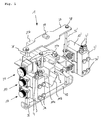
- FIG. 1 and 2 an exemplary embodiment of the inventive adjustment system 1 is shown with a preform 2 smaller size (for example, the above-mentioned PCO 28 mm).
- the adjustment system 1 is in its working position.
- the frame of the Adjustment system 1 is formed from the support rods 36, 36 ', which are connected at their upper ends via a transverse strut 37, that is screwed with corresponding screws 38, are.
- a fastening device 39 On the transverse strut 37 is a fastening device 39, which optionally serves for the attachment of longitudinal struts, which extend along a transport path and connect to other adjustment systems (not shown).
- the support rods 36, 36 ' are connected via a head guard 40, which has rounded free ends, in particular to avoid head injuries to the operators.
- the head guard 40 may otherwise have a rubberized bottom.
- the adjustment units 10, 10' are mounted, which serve for a horizontal adjustment of the guide devices 11, 11 '.
- the adjoining setting units 10 and 10 'each comprise similarly designed guide devices 11, 11'.
- the L-profile with the bent sheet 11b, 11b ' is in each case by means of a screw 7, 7' attached to the setting unit 10, 10 '.
- the two adjusting units 10, 10 'arranged above have guide profiles 11, 11' (in each case mirror-symmetrically arranged) Z-profiles 11a, 11a '. These are by means of two screw 5, 5 'and 6, 6' with the respective adjustment unit 10, 10 ' connected. The screw 6, 6 'takes place at a mounting portion 14a, 14a' of the adjustment unit 10, 10 '.
- the preform 2 rests with its collar 2b, so that it can be transported along or removed along a transport path that is generally inclined.
- a spring 19, 19 ' whose function will be explained below.
- a height adjustment device 20 Above the setting unit 10, 10 'with the Z-profile 11a, 11a' is arranged a height adjustment device 20, here on the left side, with which a height guide unit 22, (here in the form of a C-profile 22b) in the vertical direction relative to the top or mouth opening of the preform 2 can be adjusted.
- the distance from the underside of the C-profile 22b to the collar 2b of the preform 2 is minimal here and is given as h min .
- the height adjustment device 20 is in turn mounted on the support rod 36 and includes a lever arm 21 which is pivotally mounted about a pivot axis S 1 .
- the C-profile 22b is also pivotally mounted and that with respect to the (second) pivot axis S 2nd Approximately in the middle of the lever arm 21 is further provided a substantially vertically downwardly projecting U-shaped bracket 25 which is arranged between a first ball head element 23 and a second ball head element 24 or between two respective intermediate discs 26 and 27.
- the vertical position of the C-profile 22b may be changed (ie in this case moved from the initial position shown to a higher vertical position).
- the exact operation of the height adjustment device 20 is described below, in connection with Fig. 8 explained in detail.
- a pneumatic supply device 3, 3 ' is arranged on the outside of the setting units 10, 10', which is concretely screwed laterally to the setting units 10, 10 'by means of the screws 3a, 3a'.
- connections for compressed air 4, 4' are provided on the upper side of the pneumatic supply device 3, 3 'in each case.
- the distance between the two Z-profiles 11a and 11a 'for receiving or holding the (smaller) preform 2 is indicated here with A min .
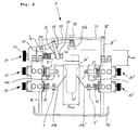
- the adjustment system 1 according to the invention with a larger preform 2 ' is shown (eg a preform according to WH 35 mm).
- the inventive adjustment system 1 was compared to its in the FIGS. 1 and 2 shown output or working position (A min , h min ) brought into a maximum position (A max , h max ).
- the distance A max is due to the wider collar 2 b 'of the preform 2', wherein the side guides 11 b, 11 b '(that is, in each case the L-profiles with the upwardly bent sheet metal 11 b, 11 b') have a greater mutual distance, since the diameter of the cylindrical body 2a 'of the preform 2' has a larger diameter.
- the height adjustment device 20 was from her in the Fig. 1 and 2 moved out starting position shown.
- the distance from the bottom of the C-profile 22b to the collar 2b 'of the larger preform 2' is, as mentioned above, now h max .
- the lever arm 21 of the height adjustment device 20 has accordingly moved upwards and has been pivoted about the (first) pivot axis S 1 .
- This movement was correspondingly converted into a vertical movement of the C-profile 22b (pivoted) at the free end 21a of the lever arm (the arrangement of the C-profile 22b on the pivot axis S 2 causes the C-profile 22b and the lower side of the C, respectively Profiles parallel to the top or the mouth opening of the preform 2 'remains).
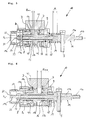
- an adjusting unit 10, 10 ' according to the invention is shown by way of example in two different positions, once with a minimum stroke (H min ) and once with a maximum stroke (H max ) for the changeover from one preform size to another preform size.
- H min minimum stroke
- H max maximum stroke
- the two FIGS. 5 and 6 Also, in terms of the mutual distance between the back of the mounting portion 14 a and the front edge of the piston-like member 12, which is here indicated as Mass M, different.
- the exact functioning of the setting unit 10, 10 is explained in more detail below:
- the outer wall part 8 and the inner wall part 9 together with the top of the middle wall part 43 and with the underside of the middle wall part 44, the housing of the setting unit 10.
- the wave-like element 14 with the mounting portion 14a, the inner threaded portion 14b and the outer threaded portion 14c arranged.
- the screw connection 5 for the underside of the Z-profile 11a also extends through the fastening section 14a of the wave-like element 14.
- the piston-like element 12 Coaxially with the wave-like element 14, the piston-like element 12 is arranged, ie in the area from the male threaded portion 14c to at most the rear of the fastening portion 14a of the wave-like element 14.
- the wave-like element 14 can thereby (horizontally) slide within the piston-like element 12 to move back and forth.
- the movement of the piston-like element 12 along the horizontal axis X 1 of the setting unit 10 is achieved by twisting the nut 52, which is separated from the piston-like element 12 by the disc 53, so that the dimension M between the leading edge of the piston-like member 12 and the back of the attachment portion 14a of the shaft-like member 14 becomes larger.
- Such a dimension M will be chosen especially for small preform sizes.
- Fig. 6 illustrates that the Mass M go to zero, ie the attachment portion 14 a will rest directly against the front edge of the piston-like element 12 with its rear side.
- the piston-like element 12 comprises a shaft part 12a and a piston part 12b.
- the outwardly directed portion of the shaft portion 12a of the piston-like member 12 is at least partially coaxially enclosed by a Hubeinstellelement 17, which in turn is arranged coaxially with the wave-like element 14 of the horizontal axis X 1 and the piston-like element 12.
- the Hubeinstellelement 17 forms on its outer side together with the plastic lid 51 in the Fig. 7 Since the Hubeinstellelement 17 has a threaded portion 17a, which cooperates with a corresponding threaded portion 8a of the outer wall portion 8, the Hubeinstellelement 17 can be adjusted horizontally relative to the piston-like element 12 and the shaft-like element 14.
- an air chamber is formed within the setting unit 10, which is divided by the piston portion 12b of the piston-like member 12 into a first (left) air chamber side 13a and a second (right) air chamber side 13b.
- the inner wall part 9 forms an inner or second stop 16 for the piston part 12b and the Hubeinstellelement 17 forms an outer or first stop 15 for the piston part 12b.
- the outer or first stop 15 is formed in particular by the end face of the Hubeinstellelements 17 and can be adjusted due to the threaded connection 17a with the outer wall part 8 and its threaded portion 8a in the horizontal direction. In this way, the stroke for changing from one preform size to another preform size can be made variable.
- the Hubeinstellelement 17 is screwed with the first stop 15 far into the first air chamber side 13a, so that the remaining stroke for the piston part 12b is minimal, which is referred to herein by H min .
- the piston part 12b bears against the second stop 16 of the inner wall part 9.
- the stroke adjusting element 17 with the first stop 15 is almost completely unscrewed from the first air chamber side 13a, so that a maximum stroke (H max ) in the direction of the second stop 16 on the inner wall part 9 results for the piston part 12b.
- Both the first air chamber side 13a and the second air chamber side 13b has an inlet for the compressed air D necessary for the execution of a piston stroke (The inlets are schematically indicated here by the vertical arrows).
- the piston-like element 12 can also be moved well with respect to the Hubeinstellelement 17 and the inner wall part 9, each slide rings 49 and 50 are provided.
- the fastening portion 14a of the wave-like element 14 one also recognizes the inwardly directed threaded portion 14b which, as in FIG Fig. 2 serves to accommodate a nut 6, with which the middle part of the Z-profile 11a can be attached.
- the lower part of the Z-profile 11a becomes, as also in Fig. 2 to see attached via the screw 5 on the mounting portion 14a.
- the minimum stroke H min to accomplish a (rather small) size difference in the successive preforms.
- the in Fig. 6 shown position can be triggered by applying the first air chamber side 13a with compressed air, a maximum stroke H max , to accomplish a change from a relatively large preform size to a much smaller preform size.
- both the stroke H and the distance M can thus be changed in a simple manner by an operator from the outside of the setting unit 10, which results in a high degree of variability with regard to the respective preform sizes, as well as a very quick changeover from one to the next (or next) preform size.
- the Fig. 7 illustrates again a frontal view of two adjustment units 10 and a height adjustment device 20 in the mounted position on the support rod 36.
- the support rod 36 At the upper end of the support rod 36 is again the cross member 37 with the fixture arranged thereon 39.
- the head protection 40 At the other end of the support rod 36 is in turn the head protection 40 with a rounded free end to recognize.
- the pneumatic supply device 3 is screwed by means of the screws 3a.
- the two adjustment units 10 comprise in particular the rotary knob 41, which on its outer surface - as in connection with FIGS. 5 and 6 described - is formed by the plastic lid 51.
- the height adjustment device 20 has a rotary knob 42 whose respective position is indicated by means of a digital display 45.
- Fig. 8 Finally, a detailed view of the inventive height adjustment device 20 is illustrated.
- the corresponding height guide unit 22 is not formed by a C-profile, but by a support for a linkage 22a - but this does not matter for the operation of the height adjustment device 20.
- the height guide unit 22 is in turn articulated on the lever arm 21 via the pivot axis S 2 .
- the lever arm 21 in turn is pivotally mounted on the base part 48 of the height adjustment device 20 via the pivot axis S 1 .
- the base part 48 is in turn mounted on the fastening device 35 on the outer part 47 of the height adjustment device 20.
- the rotary knob 42 On the outer part 47, the rotary knob 42 is arranged which, as can be seen, is sprayed around a nut 32, wherein the nut 32 forms the end portion of a longitudinal adjustment device 28 (or a longitudinal adjustment).
- the longitudinal adjustment device 28 (or the longitudinal adjustment shaft) is guided through the outer part 47 and through the base part 48 by means of a guide sleeve 33.
- a first ball head element 23 is first arranged (ie separately from the guide sleeve 33), wherein at the kugelkopf workedem end of the first ball head element 23 a disc 26 is arranged, which in turn on the outside of the U-shaped Strap 25 is present.
- a disc 27 is arranged, which in turn serves as a support for the second ball head element 24, which is fixed at the free end of Longitudinal adjustment 28 is mounted (here by means of a nut 54 attached).
- a sliding member 31 is arranged, which is held by a mandrel 30.
- the U-shaped bracket 25 is secured by means of the screw 34 to the lever arm 21.
- the height adjustment device 20 is mounted as a whole on the support rod 36, at its upper end, in turn, the cross member 37 is screwed.
- a spring 29 is arranged, which ensures a bias of the first ball head element 23 relative to the Lekssverstell issued 28 and the connected knob 42.
- the second ball head element 24 and its associated disc 27 dissolves slightly from the U-shaped bracket 25, with the result that due to the spring force, which acting on the first ball head element 23, the discs 26 and 27 on the associated ball head surfaces (slidably) obliquely and it comes to a tilting of the U-shaped bracket with a simultaneous upward movement of the same.
- the pivotal movement of the lever arm 21 is effected about the pivot axis S1, which in turn has the vertical upward movement of the height guide unit 22 result.
- the movement of the longitudinal adjustment device 28 is designated by the arrow P H , the vertical movement of the height guide unit 22 and the second pivot axis S2 with the arrow P V and the tilting / pivoting movement of the U-shaped bracket 25 indicated by the arrow P K / S.
Landscapes
- Engineering & Computer Science (AREA)
- Mechanical Engineering (AREA)
- Physics & Mathematics (AREA)
- Fluid Mechanics (AREA)
- Manufacturing & Machinery (AREA)
- General Engineering & Computer Science (AREA)
- Blow-Moulding Or Thermoforming Of Plastics Or The Like (AREA)
- Processing And Handling Of Plastics And Other Materials For Molding In General (AREA)
Abstract
Die vorliegende Erfindung ist gerichtet auf ein Verstellsystem, insbesondere zum Verstellen des gegenseitigen Abstands von zumindest zwei Führungsvorrichtungen (11, 11') für den Transport von etwa Vorformlingen (2) für Kunststoffbehälter, wobei die zumindest zwei Führungsvorrichtungen (11, 11') jeweils mit einer Einstelleinheit (10, 10') verbunden sind, wobei die Einstelleinheit (10, 10') zumindest jeweils ein kolbenartiges Element (12, 12') umfasst, welches auf pneumatische Weise zwischen einem ersten Anschlag (15, 15') und einem zweiten Anschlag (16, 16') innerhalb der Einstelleinheit (1) hin und her bewegbar ist.The present invention is directed to an adjustment system, in particular for adjusting the mutual distance of at least two guide devices (11, 11 ') for the transport of about preforms (2) for plastic containers, wherein the at least two guide devices (11, 11') each with a setting unit (10, 10 ') are connected, wherein the adjusting unit (10, 10') at least in each case a piston-like element (12, 12 '), which in a pneumatic manner between a first stop (15, 15') and a second Stop (16, 16 ') within the setting unit (1) is movable back and forth.
Description
Die Erfindung betrifft ein pneumatisches Verstellsystem zum Verstellen des gegenseitigen Abstands von zumindest zwei Führungsvorrichtungen, beispielsweise Führungsschienen für den Ab- bzw. Weitertransport von etwa Vorformlingen für Kunststoffbehälter, von einem Rollensortierer zur weiteren Bearbeitung in beispielsweise einer nachgeschalteten Inspektions- und Auswerfereinheit.The invention relates to a pneumatic adjustment system for adjusting the mutual distance of at least two guide devices, such as guide rails for the removal or further transport of about preforms for plastic containers, from a roller sorter for further processing in, for example, a downstream inspection and ejector unit.
Zur Ein- bzw. Verstellung des gegenseitigen Abstands der Führungsschienen, auf denen die Vorformlinge zum Transport jeweils mit ihrem Kragen aufliegen - also zur Breiteneinstellung, wie sie etwa bei einem Wechsel der Vorformlingsgrösse bzw. der Breite des Vorformlingskragens erforderlich wird - war es bislang üblich, die entsprechenden Breitenjustiereinheiten entlang der Transportstrecke jeweils manuell zu betätigen, d.h. über entsprechende Justierschrauben einzeln zu verstellen, wie es etwa in der
Diese Vorgehensweise hat sich in der Praxis an sich bewährt; zuletzt wurde allerdings, insbesondere auch im Hinblick auf die hohen Stillstandskosten der nachgeschalteten Streckblas- und Abfüllanlagen, der Wunsch nach einer (noch) effizienteren Umstellungsmöglichkeit von einer Vorformlingsgrösse auf eine andere, lauter.This approach has proven itself in practice; However, the desire for a (even) more efficient conversion option from one preform size to another has become louder, especially in view of the high downtime costs of downstream stretch blow molding and filling lines.
Es ist daher die Aufgabe der vorliegenden Erfindung, ein Verstellsystem bereitzustellen, mittels dem ein Wechsel von einer Vorformlingsgrösse auf eine andere, bei im Wesentlichen gleicher Zuverlässigkeit und Genauigkeit, zeitlich schneller bewerkstelligt werden kann.It is therefore the object of the present invention to provide an adjustment system by means of which a change from one preform size to another, with substantially the same reliability and accuracy, can be accomplished faster in time.
Diese Aufgabe wird erfindungsgemäss gelöst durch ein Verstellsystem, insbesondere zum Einstellen des gegenseitigen Abstands von zumindest zwei Führungsvorrichtungen für den Transport von etwa Vorformlingen für Kunststoffbehälter, wobei die zumindest zwei Führungsvorrichtungen jeweils mit einer Einstelleinheit verbunden sind, wobei die Einstelleinheit zumindest jeweils ein kolbenartiges Element umfasst, welches auf pneumatische Weise zwischen einem ersten Anschlag und einem zweiten Anschlag innerhalb der Einstelleinheit hin und her bewegbar ist.This object is achieved according to the invention by an adjustment system, in particular for adjusting the mutual spacing of at least two guide devices for transporting preforms for plastic containers, wherein the at least two guide devices are each connected to an adjustment unit, wherein the adjustment unit comprises at least one piston-like element each, which is movable in a pneumatic manner between a first stop and a second stop within the setting back and forth.
Die Führungsvorrichtungen sind dabei bevorzugt einmal in Form von zwei sich spiegelsymmetrisch gegenüberliegenden Z-Profilen ausgebildet (d.h. zur Auflage des Kragens der Vorformlinge auf der Oberseite und ggf. zum Abrutschen der Vorformlinge entlang der Transportstrecke) sowie weiter vorzugsweise in Form von zwei sich spiegelsymmetrisch gegenüberliegenden L-Profilen mit daran befestigten, abgeknickten Blechen (d.h. zur seitlichen Führung der zylindrischen Vorformlingskörper) ausgebildet. Bei einer Umstellung von Vorformlingen gemäss PCO 28 mm (Standard für PET-Vorformlinge, PCO = "Plastic Closure Only") auf Vorformlinge gemäss WH 38 mm (WH = "Weithals") muss beispielsweise auf jeder Seite ein Hub von 5 mm überwunden werden (d.h. jeweils nach aussen).The guide devices are preferably once in the form of two mirror-symmetrically opposite Z-profiles formed (ie for supporting the collar of the preforms on the top and possibly for slipping of the preforms along the transport path) and more preferably in the form of two mirror-symmetrically opposite L. Profiles attached thereto, kinked sheets (ie for lateral guidance of the cylindrical preform body) is formed. When converting preforms according to
In einer bevorzugten Ausführungsform der vorliegenden Erfindung definiert die Einstelleinheit jeweils eine Luftkammer, in welcher jedenfalls Teile des kolbenartigen Elements beweglich gelagert sind. Bevorzugt ist dabei das kolbenartige Element in Form einer Kolbenstange ausgebildet, welche einen Schaftteil und einen Kolbenteil aufweist. Weiter vorzugsweise unterteilt insbesondere der Kolbenteil der Kolbenstange die Luftkammer in eine erste Luftkammerseite (nach aussen hin liegend) und eine zweite Luftkammerseite (nach innen hin liegend). Der Kolbenteil stösst dabei an die Unter- sowie an die Oberseite der Luftkammer an und kann, zusammen mit dem Schaftteil, horizontal gleitend in der Luftkammer hin und her bewegt werden. Bevorzugt sind die erste und die zweite Luftkammerseite jeweils mit einer pneumatischen Versorgungseinrichtung verbunden, so dass jede der beiden Luftkammerseiten über entsprechende Leitungen oder Kanäle separat mit Druckluft beaufschlagt werden kann, so dass ein Hub des Kolbens, nach aussen oder nach innen, ausgeführt werden kann. Die pneumatische Versorgungseinrichtung ist dabei vorzugsweise abnehmbar an der Aussenseite der jeweiligen Einstelleinheit angeordnet. Die pneumatischen Versorgungseinrichtungen (d.h. von sämtlichen Einstelleinheiten entlang der Transportstrecke) werden bevorzugt mittels eines zentralen Hebels betätigt, so dass der jeweils eingestellte Kolbenhub bei allen Einstelleinheiten gleichzeitig erfolgen kann.In a preferred embodiment of the present invention, the adjustment unit each defines an air chamber, in which at least parts of the piston-like element are movably mounted. In this case, the piston-like element is preferably designed in the form of a piston rod, which has a shaft part and a piston part. Further preferably divided in particular the Piston part of the piston rod, the air chamber in a first air chamber side (lying outward) and a second air chamber side (lying inwards). The piston part abuts the bottom and the top of the air chamber and, together with the shaft part, can be moved horizontally in the air chamber to move it back and forth. Preferably, the first and the second air chamber side are each connected to a pneumatic supply device, so that each of the two air chamber sides can be acted upon via corresponding lines or channels separately with compressed air, so that a stroke of the piston, to the outside or to the inside, can be performed. The pneumatic supply device is preferably arranged detachably on the outside of the respective setting unit. The pneumatic supply devices (ie of all adjustment units along the transport path) are preferably actuated by means of a central lever, so that the respectively set piston stroke can take place simultaneously with all adjustment units.
In einer bevorzugten Ausführungsform der vorliegenden Erfindung ist zumindest einer der beiden Anschläge der Einstelleinheit verstellbar ausgebildet. Vorzugsweise ist dies der nach aussen liegende Anschlag, da dieser leichter von einer Bedienperson betätigt werden kann. Allerdings ist auch eine verstellbare Ausbildung des nach innen liegenden Anschlags denkbar.In a preferred embodiment of the present invention, at least one of the two stops of the setting unit is adjustable. Preferably, this is the outboard stop, as it can be easily operated by an operator. However, an adjustable design of the inward stop is also conceivable.
Weiter vorzugsweise ist der zumindest eine verstellbare Anschlag der Einstelleinheit an einem Hubeinstellelement ausgebildet. Das Hubeinstellelement und seine konkret als Anschlag dienende Stirnfläche kann dabei vermittels eines entsprechenden Gewindes in die erste Luftkammerseite (d.h. die nach aussen hin liegende Luftkammerseite) hineingedreht werden. Das Hubeinstellelement weist diesbezüglich an seinem nach aussen abragenden Ende eine drehknopfartige Ausgestaltung auf und ist weiterhin bevorzugt von einem Kunststoffdeckel verschlossen.Further preferably, the at least one adjustable stop of the setting unit is formed on a Hubeinstellelement. The Hubeinstellelement and its concrete serving as a stop end face can by means of a corresponding thread in the first air chamber side (ie the outward air chamber side) are screwed into it. The Hubeinstellelement has in this regard at its outwardly projecting end on a knob-like configuration and is further preferably closed by a plastic lid.
In einer noch weiteren bevorzugten Ausführungsform der vorliegenden Erfindung weist die Einstelleinheit ein wellenartiges Element auf, welches relativ zu dem kolbenartigen Element beweglich ist und mittels welchem ein Mass gegenüber dem kolbenartigen Element einstellbar ist. Vorzugsweise weist dabei der Schaftteil des kolbenartigen Elements einen Hohlschaft auf, welcher das wellenartige Element jedenfalls teilweise umgibt. Weiter vorzugsweise sind das kolbenartige Element und das wellenartige Element gleitend zueinander beweglich, d.h. das wellenartige Element gleitet innerhalb des Hohlschafts des kolbenartigen Elements. Das nach aussen hin liegende Ende des wellenartigen Elements weist einen Gewindeabschnitt auf, welcher mit einem korrespondierenden Gewindeabschnitt einer Mutter zusammenwirkt, welche auf das nach aussen hin liegende Ende des wellenartigen Elements aufgebracht ist und vorzugsweise von dem Schaftteil des kolbenartigen Elements durch ein Scheibenelement getrennt ist. Die Mutter kann, durch Abnehmen des vorerwähnten Kunststoffdeckels, von aussen her betätigt und das wellenartige Element so horizontal verstellt werden.In yet another preferred embodiment of the present invention, the adjustment unit comprises a shaft-like member which is movable relative to the piston-like member and by means of which a dimension is adjustable with respect to the piston-like member. In this case, the shaft part of the piston-like element preferably has a hollow shaft, which in any case partially surrounds the shaft-like element. More preferably, the piston-like member and the wave-like member are slidably movable relative to each other, i. the wave-like element slides within the hollow shaft of the piston-like element. The outboard end of the shaft-like member has a threaded portion which cooperates with a corresponding threaded portion of a nut which is applied to the outboard end of the shaft-like member and preferably separated from the shaft portion of the piston-like member by a disc member. The mother can, by removing the aforementioned plastic lid, operated from the outside and the wave-like element are adjusted horizontally.
An dem wellenartigen Element, vorzugsweise an einem Befestigungsabschnitt an dem nach innen liegenden Endbereich desselben, ist weiter vorzugsweise jeweils die Führungsvorrichtung (d.h. entweder mit dem Z-Profil oder aber mit dem L-Profil mit dem daran befestigten abgeknickten Blech) angeordnet bzw. befestigt.On the shaft-like element, preferably on a fastening portion at the inwardly-lying end region thereof, it is further preferable in each case for the guide device (ie either with the Z-profile or but arranged or fixed with the L-profile with the bent sheet metal attached thereto).
Weiter vorzugsweise weist das kolbenartige Element, bevorzugt dessen Schaftteil, an seinem der Führungsvorrichtung zugewandten Ende ein Hülsenelement auf. Zwischen dem Hülsenelement und dem dem Hülsenelement gegenüberliegenden Befestigungsabschnitt des wellenartigen Elements ist weiter bevorzugt eine Feder angeordnet, welche sich an dem Hülsenelement sowie an dem Befestigungsabschnitt abstützt und so eine Vorspannung erzeugt.Further preferably, the piston-like element, preferably the shaft part, at its the guide device end facing a sleeve member. Between the sleeve member and the sleeve member opposite the mounting portion of the wave-like element is further preferably arranged a spring, which is supported on the sleeve member and on the mounting portion and so generates a bias.
In einer weiteren bevorzugten Ausführungsform der vorliegenden Erfindung umgibt das Hubeinstellelement das kolbenartige Element und das wellenartige Element jedenfalls teilweise und ist relativ zu diesen beweglich. Weiter vorzugsweise sind das Hubeinstellelement und das kolbenartige Element gleitend zueinander beweglich. Die Gewindeverbindung des Hubeinstellelements wird mit einem korrespondierenden Bereich eines Aussenwandungsabschnitts der Einstelleinheit realisiert. Bevorzugt ist das kolbenartige Element koaxial zu dem wellenartigen Element ausgebildet (sowie zu der horizontalen Achse X1 der Einstelleinheit) und das Hubeinstellelement ist jedenfalls koaxial zu dem Schaftteil des kolbenartigen Elements ausgebildet (sowie zu dem wellenartigen Element und zu der horizontalen Achse X1 der Einstelleinheit).In a further preferred embodiment of the present invention, the Hubeinstellelement surrounds the piston-like element and the wave-like element in any case partially and is movable relative to these. Further preferably, the Hubeinstellelement and the piston-like element are slidably movable relative to each other. The threaded connection of the stroke adjustment element is realized with a corresponding region of an outer wall section of the adjustment unit. Preferably, the piston-like member is formed coaxially with the shaft-like member (as well as to the horizontal axis X 1 of the adjustment unit) and the stroke adjustment member is in any case formed coaxially with the shaft portion of the piston-like member (as well as the shaft-like member and the horizontal axis X 1 of the adjustment unit ).
Aufgrund der vorbeschriebenen Ausgestaltung kann also die jeweilige Bedienperson von der Aussenseite der Anlage her den Hub des kolbenartigen Elements bzw. des Kolbenteils innerhalb der Luftkammer der Einstelleinheit einstellen und darüber hinaus das Mass zwischen dem kolbenartigen Element und dem Befestigungsabschnitt des wellenartigen Elements.Due to the above-described embodiment, therefore, the respective operator from the outside of the system can adjust the stroke of the piston-like element or the piston part within the air chamber of the setting and beyond the measure between the piston-like Element and the attachment portion of the wave-like element.
Auf diese Weise kann zudem eine äusserst hohe Variabilität bei der Umstellung von einer Vorformlingsgrösse auf eine andere Vorformlingsgrösse bereitgestellt werden.In this way, in addition, a very high variability in the conversion from one preform size to another preform size can be provided.
In einer noch weiteren bevorzugten Ausführungsform der vorliegenden Erfindung umfasst das Verstellsystem zusätzlich eine Höhenverstellvorrichtung, welche zumindest aufweist: einen schwenkbar gelagerten Hebelarm, an dessen freiem Ende, vorzugsweise an dessen Unterseite, eine Höhenführungseinheit angeordnet ist; einen im Wesentlichen senkrecht vom Hebelarm (nach unten) abstehenden U-förmigen Bügel, welcher beweglich zwischen zwei Kugelkopfelementen, und vorzugsweise jeweils auf den Kugelkopfelementen beweglich angeordneten Scheiben, gelagert ist; wobei die Kugelkopfelemente vorzugsweise auf einer horizontal beweglichen Längsverstelleinrichtung angeordnet sind, wobei bevorzugt zumindest eines der Kugelkopfelemente auf der horizontal beweglichen Längsverstelleinrichtung federvorgespannt ist; und wobei aus der Ausgangsstellung der Höhenverstellvorrichtung heraus eine horizontale Vorwärtsbewegung der Längsverstelleinrichtung, d.h. im Wesentlichen in Richtung der Höhenführungseinheit, über eine Kippbewegung des U-förmigen Bügels sowie über eine (praktisch gleichzeitige) Schwenkbewegung des Hebelarms in eine im Wesentlichen vertikale Aufwärtsbewegung des freien Endes des Hebelarms sowie der Höhenführungseinheit umgesetzt wird.In yet another preferred embodiment of the present invention, the adjustment system additionally comprises a height adjustment device, which comprises at least: a pivotally mounted lever arm, at whose free end, preferably on the underside, a height guide unit is arranged; a substantially perpendicularly from the lever arm (down) projecting U-shaped bracket, which is movably between two ball head elements, and preferably in each case on the ball head elements movably arranged discs, stored; wherein the ball head elements are preferably arranged on a horizontally movable Längsverstelleinrichtung, wherein preferably at least one of the ball head elements is spring-biased on the horizontally movable Längsverstelleinrichtung; and from the home position of the height adjustment device, horizontal forward movement of the longitudinal adjustment device, i. is implemented in a substantially vertical upward movement of the free end of the lever arm and the height guide unit substantially in the direction of the height guide unit, a tilting movement of the U-shaped bracket and a (virtually simultaneous) pivotal movement of the lever arm.
Die Höhenverstellvorrichtung kann jedoch, für sich genommen, auch einen separaten Aspekt der vorliegenden Erfindung bilden, etwa als: Höhenverstellvorrichtung für eine Transportstrecke für Vorformlinge für Kunststoffbehälter, welche zumindest aufweist: einen schwenkbar gelagerten Hebelarm, an dessen freiem Ende, vorzugsweise an dessen Unterseite, eine Höhenführungseinheit angeordnet ist; einen im Wesentlichen senkrecht vom Hebelarm (nach unten) abstehenden U-förmigen Bügel, welcher beweglich zwischen zwei Kugelkopfelementen, und vorzugsweise jeweils auf den Kugelkopfelementen beweglich angeordneten Scheiben, gelagert ist; wobei die Kugelkopfelemente vorzugsweise auf einer horizontal beweglichen Längsverstelleinrichtung angeordnet sind, wobei bevorzugt zumindest eines der Kugelkopfelemente auf der horizontal beweglichen Längsverstelleinrichtung federvorgespannt ist; und wobei aus der Ausgangsstellung der Höhenverstellvorrichtung heraus eine horizontale Vorwärtsbewegung der Längsverstelleinrichtung, d.h. im Wesentlichen in Richtung der Höhenführungseinheit, über eine Kippbewegung des U-förmigen Bügels sowie eine (praktisch gleichzeitige) Schwenkbewegung des Hebelarms in eine im Wesentlichen vertikale Aufwärtsbewegung des freien Endes des Hebelarms sowie der Höhenführungseinheit umgesetzt wird.The height adjustment device, taken alone, can also form a separate aspect of the present invention, such as: height adjustment device for a transport path for preforms for plastic containers, which comprises at least: a pivotally mounted lever arm, at the free end, preferably on the underside, a height guide unit is arranged; a substantially perpendicularly from the lever arm (down) projecting U-shaped bracket, which is movably between two ball head elements, and preferably in each case on the ball head elements movably arranged discs, stored; wherein the ball head elements are preferably arranged on a horizontally movable Längsverstelleinrichtung, wherein preferably at least one of the ball head elements is spring-biased on the horizontally movable Längsverstelleinrichtung; and wherein from the initial position of the Höhenverstellvorrichtung out a horizontal forward movement of the Längsverstelleinrichtung, ie substantially in the direction of the height guide unit, via a tilting movement of the U-shaped bracket and a (virtually simultaneous) pivotal movement of the lever arm in a substantially vertical upward movement of the free end of the lever arm and the height guide unit is implemented.
Die Längsverstelleinrichtung der Höhenverstellvorrichtung weist dabei vorzugsweise eine (wiederum bevorzugt von aussen betätigbare) spindelförmige Konfiguration auf, wobei auf dem glatten Schaftabschnitt sich gegenüberliegend - getrennt durch den U-förmigen Bügel sowie die beiden beweglich angeordneten Scheiben (und ggf. ein vom U-förmigen Bügel umschlossenes Gleitteil) - die beiden Kugelkopfelemente angeordnet sind.The Längsverstelleinrichtung the height adjustment device preferably has a (again preferably operable from the outside) spindle-shaped configuration, being on the smooth shaft portion opposite - separated by the U-shaped bracket and the two movably arranged discs (and possibly one of the U-shaped bracket enclosed sliding part) - the two ball head elements are arranged.
Das vorzugsweise am freien Ende des glatten Schaftabschnitts der Längsverstelleinrichtung angeordnete (in der Regel etwas kleinere) zweite Kugelkopfelement ist dabei regelmässig fix montiert. Das andere (in der Regel etwas grössere), erste, Kugelkopfelement ist federvorgespannt, wobei sich die Feder an einer hinteren Anschlagfläche des ersten Kugelkopfelements und einem Innenwandungsabschnitt des Gehäuses der Höhenverstellvorrichtung abstützt.The preferably arranged at the free end of the smooth shaft portion of the Längsverstelleinrichtung (usually slightly smaller) second ball head element is regularly fixed. The other (usually somewhat larger), first, ball head element is spring biased, wherein the spring is supported on a rear abutment surface of the first ball head element and an inner wall portion of the housing of the height adjustment device.
Die Höhenführungseinheit kann wahlweise in Form eines Gestänges oder in Form eines C-Profils oder auf eine andere geeignete Weise, ausgebildet sein.The height guide unit can optionally be in the form of a linkage or in the form of a C-profile or in any other suitable manner.
Beispielhafte Ausführungsformen der vorliegenden Erfindung werden im Hinblick auf eine bessere Anschaulichkeit anhand der beiliegenden Zeichnungen illustriert.Exemplary embodiments of the present invention will be illustrated with reference to the accompanying drawings for a better understanding.
Es zeigt:
- Fig. 1
- eine perspektivische Ansicht eines erfindungsgemässen Verstellsystems mit einem eine erste Grösse aufweisenden Vorformling und der Höhenverstellvorrichtung in ihrer Ausgangsstellung (keine Auslenkung);
- Fig. 2
- eine seitliche Ansicht eines erfindungsgemässen Verstellsystems mit einem eine erste Grösse aufweisenden Vorformling und der Höhenverstellvorrichtung in ihrer Ausgangsstellung (keine Auslenkung);
- Fig. 3
- eine perspektivische Ansicht eines erfindungsgemässen Verstellsystems mit einem eine zweite Grösse aufweisenden Vorformling und der Höhenverstellvorrichtung in ihrer Endstellung (maximale Auslenkung);
- Fig. 4
- eine seitliche Ansicht eines erfindungsgemässen Verstellsystems mit einem eine zweite Grösse aufweisenden Vorformling und der Höhenverstellvorrichtung in ihrer Endstellung (maximale Auslenkung);
- Fig. 5
- eine seitliche Querschnittsansicht einer erfindungsgemässen Einstelleinheit (zur Breiteneinstellung) mit minimalem Hub des kolbenartigen Elements;
- Fig. 6
- eine seitliche Querschnittsansicht einer erfindungsgemässen Einstelleinheit (zur Breiteneinstellung) mit maximalem Hub des kolbenartigen Elements;
- Fig. 7
- eine Frontalansicht der Aussenseite zweier erfindungsgemässer Einstelleinheiten (zur Breiteneinstellung) sowie der Aussenseite einer erfindungsgemässen Höhenverstellvorrichtung;
- Fig. 8
- eine seitliche Querschnittsansicht einer erfindungsgemässen Höhenverstellvorrichtung in ihrer Ausgangsstellung (keine Auslenkung).
- Fig. 1
- a perspective view of an inventive adjustment system with a first size preform and the height adjustment device in its initial position (no deflection);
- Fig. 2
- a side view of an inventive adjustment system with a first size having preform and the height adjustment device in its initial position (no deflection);
- Fig. 3
- a perspective view of an inventive adjustment with a second size preform and the height adjustment device in its end position (maximum deflection);
- Fig. 4
- a side view of an inventive adjustment system with a second size preform and the height adjustment device in its end position (maximum deflection);
- Fig. 5
- a side cross-sectional view of an inventive adjustment (width adjustment) with minimal stroke of the piston-like element;
- Fig. 6
- a side cross-sectional view of an inventive adjustment (width adjustment) with maximum stroke of the piston-like element;
- Fig. 7
- a front view of the outside of two inventive adjustment units (for width adjustment) and the outside of a height adjustment device according to the invention;
- Fig. 8
- a lateral cross-sectional view of a height adjustment device according to the invention in its initial position (no deflection).
In den
An den Halterungsstangen 36, 36' sind insbesondere die Einstelleinheiten 10, 10' montiert, welche für eine horizontale Verstellung der Führungsvorrichtungen 11, 11' dienen. Die sich jeweils gegenüberliegenden Einstelleinheiten 10 und 10' umfassen dabei jeweils analog ausgebildete Führungsvorrichtungen 11, 11'. Die beiden unteren Einstelleinheiten 10, 10' umfassen als Führungsvorrichtung 11, 11' jeweils ein L-Profil 11b, 11b', an welchem ein nach oben abgeknicktes Blech angeordnet ist, welches zur seitlichen Führung des zylindrischen Körpers 2a des Vorformlings 2 dient. Das L-Profil mit dem abgeknickten Blech 11b, 11b' ist dabei jeweils mittels einer Schraubverbindung 7, 7' an der Einstelleinheit 10, 10' befestigt.On the
Die beiden oberhalb angeordneten Einstelleinheiten 10, 10' weisen als Führungsvorrichtung 11, 11' jeweils (wiederum spiegelsymmetrisch angeordnete) Z-Profile 11a, 11a' auf. Diese sind mittels zweier Schraubverbindungen 5, 5' sowie 6, 6' mit der jeweiligen Einstelleinheit 10, 10' verbunden. Die Schraubverbindung 6, 6' erfolgt dabei an einem Befestigungsabschnitt 14a, 14a' der Einstelleinheit 10, 10'. Auf der Oberseite der beiden sich gegenüberliegenden Z-Profile 11a, 11a' liegt der Vorformling 2 mit seinem Kragen 2b auf, sodass dieser entlang einer, in der Regel geneigten, Transportstrecke weiter- beziehungsweise abtransportiert werden kann.The two adjusting
Zwischen den Führungsvorrichtungen 11, 11' und der nach innen liegenden Wandung der Einstelleinheit 10, 10' ist jeweils eine Feder 19, 19' angeordnet, deren Funktion weiter unten erläutert wird. Oberhalb der Einstelleinheit 10, 10' mit dem Z-Profil 11a, 11a' ist eine Höhenverstellvorrichtung 20 angeordnet, hier auf der linken Seite, mit welcher eine Höhenführungseinheit 22, (hier in Form eines C-Profils 22b) in vertikaler Richtung gegenüber der Oberseite bzw. Mündungsöffnung des Vorformlings 2 verstellt werden kann. Der Abstand von der Unterseite des C-Profils 22b zum Kragen 2b des Vorformlings 2 ist hier minimal und wird entsprechend mit hmin angegeben.Between the
Die Höhenverstellvorrichtung 20 ist wiederum an der Halterungsstange 36 montiert und umfasst ein Hebelarm 21, welcher um eine Schwenkachse S1 schwenkbar gelagert ist. An dem freien Ende 21a des Hebelarms ist das C-Profil 22b ebenfalls schwenkbar gelagert und zwar bezüglich der (zweiten) Schwenkachse S2. Etwa in der Mitte des Hebelarmes 21 ist des Weiteren ein im Wesentlichen senkrecht nach unten abragender U-förmiger Bügel 25 vorgesehen, welcher zwischen einem ersten Kugelkopfelement 23 und einem zweiten Kugelkopfelement 24 beziehungsweise zwischen zwei jeweils dazwischen liegenden Scheiben 26 und 27 angeordnet ist. Über diese Höhenverstellvorrichtung 20 kann die vertikale Position des C-Profils 22b verändert werden (d.h. in diesem Fall von der gezeigten Ausgangsstellung aus in eine höhere vertikale Position bewegt werden). Die genaue Funktionsweise der Höhenverstellvorrichtung 20 wird weiter unten, im Zusammenhang mit
Man erkennt weiterhin, dass an der Aussenseite der Einstelleinheiten 10, 10' jeweils eine pneumatische Versorgungseinrichtung 3, 3' angeordnet ist, welche konkret mittels der Schrauben 3a, 3a' seitlich mit den Einstelleinheiten 10, 10' verschraubt ist. Auf der Oberseite der pneumatischen Versorgungseinrichtung 3, 3' sind jeweils Anschlüsse für Druckluft 4, 4' vorgesehen. Der Abstand zwischen den beiden Z-Profilen 11a und 11a' für die Aufnahme beziehungsweise Halterung des (kleineren) Vorformlings 2 wird hier mit Amin angegeben.It can further be seen that a
In den
Man erkennt des Weiteren, dass die Federn 19, 19', welche jeweils zwischen der Einstelleinheit 10, 10' und der Führungsvorrichtung 11, 11' beziehungsweise dem entsprechenden Befestigungsabschnitt 14a, 14a' der Einstelleinheit 10, 10' angeordnet sind, jeweils zusammengedrückt wurden.It can be seen further that the
Auch die Höhenverstellvorrichtung 20 wurde aus ihrer in den
Der Hebelarm 21 der Höhenverstellvorrichtung 20 hat sich entsprechend nach oben bewegt und wurde um die (erste) Schwenkachse S1 verschwenkt. Dies wurde erreicht, indem die Höhenverstellvorrichtung 20 über ihren Drehknopf 42 verstellt wurde und zwar derart, dass das erste Kugelelement 23 horizontal in Richtung des C-Profils 22b bewegt wurde, was ein Verkippen des U-förmigen Bügels 25 zusammen mit einer Gleitbewegung der jeweils anliegenden Scheiben 26, 27 ausgelöst hat sowie eine gleichzeitige Schwenkbewegung des U-förmigen Bügels 25 zusammen mit dem Hebelarm 21 relativ zu der Schwenkachse S1. Diese Bewegung wurde entsprechend umgesetzt in eine vertikale Bewegung des am freien Ende 21a des Hebelarms (schwenkbar) befestigten C-Profils 22b (die Anordnung des C-Profils 22b an der Schwenkachse S2 bewirkt, dass das C-Profil 22b beziehungsweise die Unterseite des C-Profils parallel zu der Oberseite bzw. der Mündungsöffnung des Vorformlings 2' bleibt).The
In den
Die genaue Funktionsweise der Einstelleinheit 10, 10' wird im Folgenden näher erläutert: Das Aussenwandungsteil 8 und das Innenwandungsteil 9 bilden zusammen mit der Oberseite des Mittelwandteils 43 sowie mit der Unterseite des Mittelwandteils 44 das Gehäuse der Einstelleinheit 10. Innerhalb dieses Gehäuses sind das wellenartige Element 14 mit dem Befestigungsabschnitt 14a, dem inneren Gewindeabschnitt 14b sowie dem äusseren Gewindeabschnitt 14c angeordnet. Durch den Befestigungsabschnitt 14a des wellenartigen Elements 14 hindurch verläuft im Übrigen auch die Schraubverbindung 5 für die Unterseite des Z-Profils 11a (nicht gezeigt).The exact functioning of the
Koaxial zu dem wellenartigen Element 14 ist das kolbenartige Element 12 angeordnet, d.h. im Bereich von dem Aussengewindeabschnitt 14c bis maximal zu der Rückseite des Befestigungsabschnitts 14a des wellenartigen Elements 14. Das wellenartige Element 14 kann sich dabei (horizontal) gleitend innerhalb des kolbenartigen Elements 12 hin und her bewegen. Die Bewegung des kolbenartigen Elements 12 entlang der horizontalen Achse X1 der Einstelleinheit 10 wird erreicht, indem die Mutter 52, welche durch die Scheibe 53 von dem kolbenartigen Element 12 getrennt ist, verdreht wird, sodass sich etwa bei einer Bewegung nach rechts das Mass M zwischen der Vorderkante des kolbenartigen Elements 12 und der Rückseite des Befestigungsabschnittes 14a des wellenartigen Element 14 grösser wird. Ein solches Mass M wird insbesondere für kleine Vorformlingsgrössen gewählt werden. Für grössere Vorformlingsgrössen wird, in
Das kolbenartige Element 12 umfasst, wie zu sehen, einen Schaftteil 12a sowie einen Kolbenteil 12b. Der nach aussen gerichtete Bereich des Schaftteils 12a des kolbenartigen Elements 12 wird jedenfalls zum Teil koaxial von einem Hubeinstellelement 17 umschlossen, welches wiederum koaxial zu dem wellenartigen Element 14 der horizontalen Achse X1 sowie dem kolbenartigen Element 12 angeordnet ist. Das Hubeinstellelement 17 bildet an seiner Aussenseite zusammen mit dem Kunststoffdeckel 51 den in
Zwischen dem Aussenwandungsteil 8 und dem Innenwandungsteil 9 sowie der Ober- und Unterseite des Mittelwandteils 42, 43 wird innerhalb der Einstelleinheit 10 eine Luftkammer ausgebildet, welche von dem Kolbenteil 12b des kolbenartigen Elements 12 unterteilt wird in eine erste (linke) Luftkammerseite 13a sowie eine zweite (rechte) Luftkammerseite 13b. Das Innenwandungsteil 9 bildet dabei einen inneren beziehungsweise zweiten Anschlag 16 für das Kolbenteil 12b und das Hubeinstellelement 17 bildet einen äusseren bzw. ersten Anschlag 15 für das Kolbenteil 12b aus. Der äussere beziehungsweise erste Anschlag 15 wird insbesondere gebildet durch die Stirnseite des Hubeinstellelements 17 und kann aufgrund der Gewindeverbindung 17a mit dem Aussenwandungsteil 8 bzw. dessen Gewindeabschnitt 8a in horizontaler Richtung verstellt werden. Auf diese Weise kann der Hub zum Umstellen von einer Vorformlingsgrösse auf eine andere Vorformlingsgrösse variabel gestaltet werden.Between the
Gemäss
Damit das kolbenartige Element 12 auch gut gegenüber dem Hubeinstellelement 17 sowie dem Innenwandungsteil 9 bewegt werden kann, sind jeweils Gleitringe 49 und 50 vorgesehen. Am inneren Ende des Befestigungsabschnitts 14a des wellenartigen Elements 14 erkennt man ausserdem den nach innen gerichteten Gewindeabschnitt 14b, welcher, wie etwa in
Die Feder 19, welche sich an dem Hülsenelement 18 sowie an dem Befestigungsabschnitt 14a abstützt, sorgt im Übrigen für die notwendige Vorspannung zwischen dem kolbenartigen Element 12 und dem wellenartigen Element 14. Bei der in
Ingesamt können somit erfindungsgemäss sowohl der Hub H als auch das Abstandsmass M von einer Bedienperson von der Aussenseite der Einstelleinheit 10 her auf einfache Weise verändert werden, was sowohl eine hohe Variabilität hinsichtlich der jeweiligen Vorformlingsgrössen gewährleistet als auch eine zeitlich sehr schnelle Umstellung von einer auf die andere (bzw. nächste) Vorformlingsgrösse.Overall, according to the invention, both the stroke H and the distance M can thus be changed in a simple manner by an operator from the outside of the
Die
In
Auf der Aussenseite der Längsverstelleinrichtung 28 bzw. des Längsverstellschafts ist zunächst ein erstes Kugelkopfelement 23 angeordnet (d.h. separat von der Führungshülse 33), wobei an dem kugelkopfseitigem Ende des ersten Kugelkopfelements 23 eine Scheibe 26 angeordnet ist, welche ihrerseits an der Aussenseite des U-förmigen Bügels 25 anliegt. Auf der anderen Seite U-förmigen Bügels 25 ist wiederum eine Scheibe 27 angeordnet, welche ihrerseits als Unterlage für das zweite Kugelkopfelement 24 dient, welches fest am freien Ende der Längsverstelleinrichtung 28 angebracht ist (hier mittels einer Mutter 54 befestigt).On the outside of the
Innerhalb des U-förmigen Bügels 25 ist ein Gleitteil 31 angeordnet, welches von einem Dorn 30 gehalten wird. Der U-förmige Bügel 25 ist vermittels der Schraube 34 an dem Hebelarm 21 befestigt. Die Höhenverstellvorrichtung 20 ist als Ganzes an der Halterungsstange 36 montiert, an deren oberen Ende wiederum die Querstrebe 37 angeschraubt ist. Zwischen dem Basisteil 48 und einem hinteren Anschlag des ersten Kugelkopfelements ist eine Feder 29 angeordnet, welche für eine Vorspannung des ersten Kugelkopfelements 23 gegenüber der Längsverstelleinrichtung 28 sowie dem angeschlossenen Drehknopf 42 sorgt.Within the
Wird nun die Längsverstelleinrichtung 28 vermittels des Drehknopfes 42 in horizontaler Richtung nach rechts beziehungsweise nach innen gedreht, löst sich das zweite Kugelkopfelement 24 sowie dessen zugehörige Scheibe 27 etwas vom U-förmigen Bügel 25 ab, was zur Folge hat, dass aufgrund der Federkraft, welche auf das erste Kugelkopfelement 23 wirkt, sich die Scheiben 26 und 27 auf den zugehörigen Kugelkopfoberflächen (gleitend) schräg stellen und es zu einem Verkippen des U-förmigen Bügels bei einer gleichzeitigen Aufwärtsbewegung desselben kommt. Hierdurch wird wiederum die Schwenkbewegung des Hebelarms 21 um die Schwenkachse S1 bewirkt, welche wiederum die vertikale Aufwärtsbewegung der Höhenführungseinheit 22 zur Folge hat. Die Bewegung der Längsverstelleinrichtung 28 wird dabei mit dem Pfeil PH bezeichnet, die Vertikalbewegung der Höhenführungseinheit 22 beziehungsweise der zweiten Schwenkachse S2 mit dem Pfeil PV und die Kipp-/Schwenkbewegung des U-förmigen Bügels 25 mit dem Pfeil PK/S bezeichnet.Now, if the
Aufgrund der erfindungsgemässen Lösung kann eine äusserst feinstufige Einstellung für verschieden hohe Mündungsöffnungen der entsprechenden Vorformlinge erzielt werden.Because of the solution according to the invention, an extremely fine-grade setting can be achieved for differently high mouth openings of the corresponding preforms.
- 11
- Verstellsystemadjustment
- 2, 2'2, 2 '
- Vorformlingpreform
- 2a, 2a'2a, 2a '
- Körperbody
- 2b, 2b'2b, 2b '
- Kragencollar
- 3, 3'3, 3 '
- pneumatische Versorgungseinrichtungpneumatic supply device
- 3a, 3a'3a, 3a '
- Schraubescrew
- 4, 4'4, 4 '
- DruckluftanschlussCompressed air connection
- 5, 5'5, 5 '
- Schraubverbindung Z-ProfilScrew connection Z-profile
- 6, 6'6, 6 '
- Schraubverbindung Z-ProfilScrew connection Z-profile
- 7, 7'7, 7 '
- Schraubverbindung L-ProfilScrew connection L-profile
- 8, 8'8, 8 '
- Aussenwandungsteilouter surface portion
- 8a, 8a'8a, 8a '
- Gewindeabschnitt (Aussenwandungsteil)Thread section (outer wall part)
- 9, 9'9, 9 '
- InnenwandungsteilInnenwandungsteil
- 10, 10'10, 10 '
- Einstelleinheitadjustment
- 11, 11'11, 11 '
- Führungsvorrichtungguiding device
- 11a, 11a'11a, 11a '
- Z-ProfilZ-profile
- 11b, 11b'11b, 11b '
- L-Profil (mit abgeknicktem Blech)L-profile (with bent sheet metal)
- 12, 12'12, 12 '
- kolbenartiges Element (bzw. Kolbenstange)piston-like element (or piston rod)
- 12a, 12a'12a, 12a '
- Schaftteilshank part
- 12b, 12b'12b, 12b '
- Kolbenteilpiston part
- 13a, 13a'13a, 13a '
- erste Luftkammerseitefirst air chamber side
- 13b, 13b'13b, 13b '
- zweite Luftkammerseitesecond air chamber side
- 14, 14'14, 14 '
- wellenartiges Elementwave-like element
- 14a, 14a'14a, 14a '
- Befestigungsabschnittattachment section
- 14b, 14b'14b, 14b '
- Gewindeabschnitt (innen)Threaded section (inside)
- 14c, 14c'14c, 14c '
- Gewindeabschnitt (aussen)Threaded section (outside)
- 15, 15'15, 15 '
- erster Anschlagfirst stop
- 16, 16'16, 16 '
- zweiter Anschlagsecond stop
- 17, 17'17, 17 '
- HubeinstellelementHubei actuator
- 17a, 17a'17a, 17a '
- Gewindeabschnitt (Hubeinstellelement)Thread section (stroke adjustment element)
- 18, 18'18, 18 '
- Hülsenelementsleeve member
- 19, 19'19, 19 '
- Feder (Einstelleinrichtung)Spring (adjusting device)
- 2020
- Höhenverstellvorrichtungheight adjustment
- 2121
- Hebelarmlever arm
- 21a21a
- freies Ende Hebelarmfree end lever arm
- 2222
- HöhenführungseinheitHeight Control Unit
- 22a22a
- Gestänge (Halterung)Linkage (bracket)
- 22b22b
- C-ProfilC-section
- 2323
- erstes Kugelkopfelementfirst ball head element
- 2424
- zweites Kugelkopfelementsecond ball head element
- 2525
- U-förmiger BügelU-shaped bracket
- 2626
- Scheibedisc
- 2727
- Scheibedisc
- 2828
- Längsverstelleinrichtunglongitudinal adjustment
- 2929
- Feder (Längsverstelleinrichtung)Spring (longitudinal adjustment device)
- 3030
- Dornmandrel
- 3131
- Gleitteilslide
- 3232
- Muttermother
- 3333
- Führungshülseguide sleeve
- 3434
- Schraube (U-förmiger Bügel)Screw (U-shaped bracket)
- 3535
- Befestigungsvorrichtung (Basisteil)Fastening device (base part)
- 36, 36'36, 36 '
- Halterungsstangesupporting rod
- 3737
- Querstrebecrossmember
- 3838
- Schraubescrew
- 3939
- Befestigungsvorrichtungfastening device
- 4040
- Kopfschutzhead protection
- 41, 41'41, 41 '
- Drehknopf (Einstelleinheit)Rotary knob (adjustment unit)
- 42, 42'42, 42 '
- Drehknopf (Höhenverstellvorrichtung)Rotary knob (height adjustment device)
- 43, 43'43, 43 '
- Mittelwandteil (Oberseite)Middle wall part (top)
- 44, 44'44, 44 '
- Mittelwandteil (Unterseite)Middle wall part (underside)
- 45, 45'45, 45 '
- DigitalanzeigeDigital display
- 46, 46'46, 46 '
- Sicherheitsschraube (mit Unterlegscheibe)Safety screw (with washer)
- 4747
- Aussenteil HöhenverstellungOutside part height adjustment
- 4848
- Basisteil HöhenverstellvorrichtungBase part height adjustment device
- 49, 49'49, 49 '
- Gleitring (Hubeinstellelement)Sliding ring (stroke adjusting element)
- 50, 50'50, 50 '
- Gleitring (Innenwandungsteil)Sliding ring (inner wall part)
- 51, 51'51, 51 '
- KunststoffdeckelPlastic lid
- 52, 52'52, 52 '
- Muttermother
- 53, 53'53, 53 '
- Scheibedisc
- Amin A min
- minimaler Abstandminimum distance
- Amax A max
- maximaler Abstandmaximum distance
- DD
- Druckluftcompressed air
- hmin h min
- minimale Höheminimum height
- hmax h max
- maximale Höhemaximum height
- Hmin H min
- minimaler Hubminimal stroke
- Hmax H max
- maximaler Hubmaximum stroke
- MM
- Massmeasure
- PH P H
- HorizontalbewegungHorizontal movement
- PV P V
- Vertikalbewegungvertical movement
- PK/S P K / S
- Kipp-/SchwenkbewegungTilt / swivel movement
- S1 S 1
- Schwenkachseswivel axis
- S2 S 2
- Schwenkachseswivel axis
- X1 X 1
- horizontale Achse Einstelleinheithorizontal axis adjustment unit
Claims (16)
Applications Claiming Priority (1)
| Application Number | Priority Date | Filing Date | Title |
|---|---|---|---|
| CH00672/15A CH711070B1 (en) | 2015-05-13 | 2015-05-13 | Pneumatic adjustment system. |
Publications (3)
| Publication Number | Publication Date |
|---|---|
| EP3093259A2 true EP3093259A2 (en) | 2016-11-16 |
| EP3093259A3 EP3093259A3 (en) | 2017-04-05 |
| EP3093259B1 EP3093259B1 (en) | 2019-10-09 |
Family
ID=53793887
Family Applications (1)
| Application Number | Title | Priority Date | Filing Date |
|---|---|---|---|
| EP16169204.1A Active EP3093259B1 (en) | 2015-05-13 | 2016-05-11 | Pneumatic adjusting system |
Country Status (4)
| Country | Link |
|---|---|
| US (1) | US9782923B2 (en) |
| EP (1) | EP3093259B1 (en) |
| CN (1) | CN106144523B (en) |
| CH (1) | CH711070B1 (en) |
Cited By (3)
| Publication number | Priority date | Publication date | Assignee | Title |
|---|---|---|---|---|
| EP3453648A1 (en) * | 2017-09-07 | 2019-03-13 | M. Tanner AG | Inlet device |
| EP3678838B1 (en) | 2017-09-06 | 2022-01-19 | Sidel Participations | Method and device for adjusting a preform conveyor |
| EP3833526B1 (en) | 2018-08-09 | 2022-09-07 | Sidel Participations | Device for feeding preforms having variable-position guide elements |
Families Citing this family (4)
| Publication number | Priority date | Publication date | Assignee | Title |
|---|---|---|---|---|
| DE102015205984A1 (en) * | 2015-04-02 | 2016-10-06 | Krones Aktiengesellschaft | Method and guide system for the transport of containers or container components in industrial plants for container production and / or product filling |
| FR3080056B1 (en) * | 2018-04-16 | 2020-03-20 | Sidel Participations | METHOD FOR POSITIONING THERMAL PROTECTION RAMPS IN A PREFORM HEATING STATION |
| FR3092099B1 (en) * | 2019-01-24 | 2021-01-29 | Tiama | Method and device for conveying containers in suspended position |
| CN114348609B (en) * | 2022-01-08 | 2023-06-16 | 岳西县田园东方生态农林发展有限公司 | Receiving adjusting part for dividing green body for automatic production system |
Citations (1)
| Publication number | Priority date | Publication date | Assignee | Title |
|---|---|---|---|---|
| EP2848558A1 (en) | 2013-09-16 | 2015-03-18 | M. Tanner AG | Adjusting system |
Family Cites Families (11)
| Publication number | Priority date | Publication date | Assignee | Title |
|---|---|---|---|---|
| US5542789A (en) * | 1994-02-22 | 1996-08-06 | Aidlin; Stephen H. | Multi position bottle guide assembly |
| FR2781470B1 (en) * | 1998-07-21 | 2000-10-13 | Netra Systems | AIR CONVEYOR FOR TRANSPORTING ARTICLES AND METHOD FOR RELEASING ARTICLES |
| EP1277677A1 (en) * | 2001-07-20 | 2003-01-22 | Rexnord Marbett S.p.A. | Guide postioner for a conveyor |
| US6827203B2 (en) * | 2001-11-02 | 2004-12-07 | Rexnord Marbett S.P.A. | Positioning system of conveyor guides |
| FR2870224B1 (en) * | 2004-05-13 | 2006-08-11 | Herve Deflandre | LATERAL GUIDE DEVICE FOR HANDLING SYSTEM AND HANDLING SYSTEM USING SUCH A DEVICE |
| US8132665B2 (en) * | 2008-05-20 | 2012-03-13 | Advanced Manufacturing Technology For Bottles, Inc. | Position control apparatus and methods |
| US7717254B2 (en) * | 2008-05-29 | 2010-05-18 | Corning Incorporated | Glass sheet guidance system and method for guiding glass sheets |
| CH699222A1 (en) * | 2008-07-17 | 2010-01-29 | M Tanner Ag | Device and method for separating cylindrical bodies. |
| DE102009016593B4 (en) * | 2009-04-08 | 2021-10-14 | Krones Aktiengesellschaft | Device for transporting preforms |
| ITPR20090008U1 (en) * | 2009-09-14 | 2011-03-15 | Lanfranchi Srl | SYSTEM FOR CHANGING THE NECK SIZE DIMENSION ON AN AIR TRANSPORT DEVICE FOR PLASTIC CONTAINERS OR PREFORMATIONS |
| DE102011118519B4 (en) * | 2011-11-15 | 2019-10-17 | Festo Ag & Co. Kg | Fluid operated linear actuator |
-
2015
- 2015-05-13 CH CH00672/15A patent/CH711070B1/en unknown
-
2016
- 2016-05-06 US US15/148,182 patent/US9782923B2/en not_active Expired - Fee Related
- 2016-05-11 EP EP16169204.1A patent/EP3093259B1/en active Active
- 2016-05-13 CN CN201610589657.5A patent/CN106144523B/en not_active Expired - Fee Related
Patent Citations (1)
| Publication number | Priority date | Publication date | Assignee | Title |
|---|---|---|---|---|
| EP2848558A1 (en) | 2013-09-16 | 2015-03-18 | M. Tanner AG | Adjusting system |
Cited By (6)
| Publication number | Priority date | Publication date | Assignee | Title |
|---|---|---|---|---|
| EP3678838B1 (en) | 2017-09-06 | 2022-01-19 | Sidel Participations | Method and device for adjusting a preform conveyor |
| EP3453648A1 (en) * | 2017-09-07 | 2019-03-13 | M. Tanner AG | Inlet device |
| CN109466908A (en) * | 2017-09-07 | 2019-03-15 | M.坦纳股份公司 | Feedway |
| US10569462B2 (en) | 2017-09-07 | 2020-02-25 | M. Tanner Ag | Feed device |
| EP3833526B1 (en) | 2018-08-09 | 2022-09-07 | Sidel Participations | Device for feeding preforms having variable-position guide elements |
| US11738497B2 (en) * | 2018-08-09 | 2023-08-29 | Sidel Participations | Device for feeding preforms having variable-position guide elements |
Also Published As
| Publication number | Publication date |
|---|---|
| EP3093259A3 (en) | 2017-04-05 |
| CN106144523B (en) | 2020-03-10 |
| CN106144523A (en) | 2016-11-23 |
| US9782923B2 (en) | 2017-10-10 |
| EP3093259B1 (en) | 2019-10-09 |
| CH711070B1 (en) | 2022-03-31 |
| CH711070A1 (en) | 2016-11-15 |
| US20160332354A1 (en) | 2016-11-17 |
Similar Documents
| Publication | Publication Date | Title |
|---|---|---|
| EP3093259B1 (en) | Pneumatic adjusting system | |
| EP2604411B1 (en) | Device for conveying plastic preforms | |
| CH397224A (en) | Device for the production of hollow bodies from thermoplastic material | |
| EP3403738B1 (en) | Sheet metal bending machine | |
| EP0393562B1 (en) | Longitudinal folding device | |
| EP2848558B1 (en) | Adjusting system | |
| EP3094466B1 (en) | Method and device for supporting a plastics profile | |
| WO2012100357A1 (en) | Conveying device for cylindrical members, comprising running rails inclined in the direction of travel | |
| EP2877298B1 (en) | Direct or indirect metal pipe extrusion process, metal pipe extrusion press and extruded metal pipe | |
| EP2353440B1 (en) | Fitting for a corner cupboard and corner cupboard | |
| EP3359367A1 (en) | Apparatus and method for deforming plastics parisons to form plastics containers with coupling device | |
| DE1548210A1 (en) | Machine for testing glass containers or the like. | |
| DE3015203A1 (en) | Bottle conveyor with star wheel lockable to stop bottles - has wheel carried on support with limited parallel movement against damper | |
| DE1288297B (en) | Extrusion device for the production of hoses from thermoplastic material | |
| DE60001269T2 (en) | MOLDING UNIT WHICH HAS AN IMPROVED MOLD CLAMPING DEVICE AND EXTRUSION BLOW MOLDING MACHINE WHERE THIS MOLDING CLAMPING DEVICE IS USED | |
| DE3021442C2 (en) | Folder gluer | |
| DE19501762C2 (en) | Channel arrangement for transferring a glass drop from a drop distributor to a preform of a glass machine | |
| DE19638075C1 (en) | Braking device for a movable component of a furniture element, in particular upholstered furniture element | |
| DE7537193U (en) | ROTATING DEVICE | |
| DE2106478C3 (en) | Guide and vibration damping device on the feed device of a machine tool | |
| DE10052668C1 (en) | Paddle wheel for printed product processing machine uses adjustable braking tongues for providing variable braking effect | |
| WO2020244737A1 (en) | Apparatus for guiding a film tube | |
| DE2637154A1 (en) | Machine for closing folded boxes of different size - has light barrier with vertically spaced beams adjusting closing equipment | |
| DE19732905A1 (en) | Calibrating unit for a plastics blow moulding machine | |
| DE2939085A1 (en) | DEVICE FOR TREATMENT OF KNITTED HOSES |
Legal Events
| Date | Code | Title | Description |
|---|---|---|---|
| PUAI | Public reference made under article 153(3) epc to a published international application that has entered the european phase |
Free format text: ORIGINAL CODE: 0009012 |
|
| AK | Designated contracting states |
Kind code of ref document: A2 Designated state(s): AL AT BE BG CH CY CZ DE DK EE ES FI FR GB GR HR HU IE IS IT LI LT LU LV MC MK MT NL NO PL PT RO RS SE SI SK SM TR |
|
| AX | Request for extension of the european patent |
Extension state: BA ME |
|
| PUAL | Search report despatched |
Free format text: ORIGINAL CODE: 0009013 |
|
| AK | Designated contracting states |
Kind code of ref document: A3 Designated state(s): AL AT BE BG CH CY CZ DE DK EE ES FI FR GB GR HR HU IE IS IT LI LT LU LV MC MK MT NL NO PL PT RO RS SE SI SK SM TR |
|
| AX | Request for extension of the european patent |
Extension state: BA ME |
|
| RIC1 | Information provided on ipc code assigned before grant |
Ipc: B65G 51/03 20060101AFI20170224BHEP Ipc: F15B 15/24 20060101ALN20170224BHEP |
|
| STAA | Information on the status of an ep patent application or granted ep patent |
Free format text: STATUS: REQUEST FOR EXAMINATION WAS MADE |
|
| 17P | Request for examination filed |
Effective date: 20171003 |
|
| RBV | Designated contracting states (corrected) |
Designated state(s): AL AT BE BG CH CY CZ DE DK EE ES FI FR GB GR HR HU IE IS IT LI LT LU LV MC MK MT NL NO PL PT RO RS SE SI SK SM TR |
|
| STAA | Information on the status of an ep patent application or granted ep patent |
Free format text: STATUS: EXAMINATION IS IN PROGRESS |
|
| 17Q | First examination report despatched |
Effective date: 20180205 |
|
| GRAP | Despatch of communication of intention to grant a patent |
Free format text: ORIGINAL CODE: EPIDOSNIGR1 |
|
| STAA | Information on the status of an ep patent application or granted ep patent |
Free format text: STATUS: GRANT OF PATENT IS INTENDED |
|
| RIC1 | Information provided on ipc code assigned before grant |
Ipc: B65G 51/03 20060101AFI20190404BHEP Ipc: F15B 15/24 20060101ALN20190404BHEP |
|
| INTG | Intention to grant announced |
Effective date: 20190503 |
|
| GRAS | Grant fee paid |
Free format text: ORIGINAL CODE: EPIDOSNIGR3 |
|
| GRAA | (expected) grant |
Free format text: ORIGINAL CODE: 0009210 |
|
| STAA | Information on the status of an ep patent application or granted ep patent |
Free format text: STATUS: THE PATENT HAS BEEN GRANTED |
|
| AK | Designated contracting states |
Kind code of ref document: B1 Designated state(s): AL AT BE BG CH CY CZ DE DK EE ES FI FR GB GR HR HU IE IS IT LI LT LU LV MC MK MT NL NO PL PT RO RS SE SI SK SM TR |
|
| REG | Reference to a national code |
Ref country code: GB Ref legal event code: FG4D Free format text: NOT ENGLISH |
|
| REG | Reference to a national code |
Ref country code: CH Ref legal event code: EP Ref country code: CH Ref legal event code: NV Representative=s name: PATENTANWAELTE SCHAAD, BALASS, MENZL AND PARTN, CH |
|
| REG | Reference to a national code |
Ref country code: IE Ref legal event code: FG4D Free format text: LANGUAGE OF EP DOCUMENT: GERMAN |
|
| REG | Reference to a national code |
Ref country code: DE Ref legal event code: R096 Ref document number: 502016006968 Country of ref document: DE |
|
| REG | Reference to a national code |
Ref country code: AT Ref legal event code: REF Ref document number: 1188554 Country of ref document: AT Kind code of ref document: T Effective date: 20191115 |
|
| REG | Reference to a national code |
Ref country code: NL Ref legal event code: MP Effective date: 20191009 |
|
| REG | Reference to a national code |
Ref country code: LT Ref legal event code: MG4D |
|
| PG25 | Lapsed in a contracting state [announced via postgrant information from national office to epo] |
Ref country code: PT Free format text: LAPSE BECAUSE OF FAILURE TO SUBMIT A TRANSLATION OF THE DESCRIPTION OR TO PAY THE FEE WITHIN THE PRESCRIBED TIME-LIMIT Effective date: 20200210 Ref country code: LV Free format text: LAPSE BECAUSE OF FAILURE TO SUBMIT A TRANSLATION OF THE DESCRIPTION OR TO PAY THE FEE WITHIN THE PRESCRIBED TIME-LIMIT Effective date: 20191009 Ref country code: ES Free format text: LAPSE BECAUSE OF FAILURE TO SUBMIT A TRANSLATION OF THE DESCRIPTION OR TO PAY THE FEE WITHIN THE PRESCRIBED TIME-LIMIT Effective date: 20191009 Ref country code: PL Free format text: LAPSE BECAUSE OF FAILURE TO SUBMIT A TRANSLATION OF THE DESCRIPTION OR TO PAY THE FEE WITHIN THE PRESCRIBED TIME-LIMIT Effective date: 20191009 Ref country code: LT Free format text: LAPSE BECAUSE OF FAILURE TO SUBMIT A TRANSLATION OF THE DESCRIPTION OR TO PAY THE FEE WITHIN THE PRESCRIBED TIME-LIMIT Effective date: 20191009 Ref country code: NO Free format text: LAPSE BECAUSE OF FAILURE TO SUBMIT A TRANSLATION OF THE DESCRIPTION OR TO PAY THE FEE WITHIN THE PRESCRIBED TIME-LIMIT Effective date: 20200109 Ref country code: BG Free format text: LAPSE BECAUSE OF FAILURE TO SUBMIT A TRANSLATION OF THE DESCRIPTION OR TO PAY THE FEE WITHIN THE PRESCRIBED TIME-LIMIT Effective date: 20200109 Ref country code: NL Free format text: LAPSE BECAUSE OF FAILURE TO SUBMIT A TRANSLATION OF THE DESCRIPTION OR TO PAY THE FEE WITHIN THE PRESCRIBED TIME-LIMIT Effective date: 20191009 Ref country code: SE Free format text: LAPSE BECAUSE OF FAILURE TO SUBMIT A TRANSLATION OF THE DESCRIPTION OR TO PAY THE FEE WITHIN THE PRESCRIBED TIME-LIMIT Effective date: 20191009 Ref country code: FI Free format text: LAPSE BECAUSE OF FAILURE TO SUBMIT A TRANSLATION OF THE DESCRIPTION OR TO PAY THE FEE WITHIN THE PRESCRIBED TIME-LIMIT Effective date: 20191009 Ref country code: GR Free format text: LAPSE BECAUSE OF FAILURE TO SUBMIT A TRANSLATION OF THE DESCRIPTION OR TO PAY THE FEE WITHIN THE PRESCRIBED TIME-LIMIT Effective date: 20200110 |
|
| PG25 | Lapsed in a contracting state [announced via postgrant information from national office to epo] |
Ref country code: RS Free format text: LAPSE BECAUSE OF FAILURE TO SUBMIT A TRANSLATION OF THE DESCRIPTION OR TO PAY THE FEE WITHIN THE PRESCRIBED TIME-LIMIT Effective date: 20191009 Ref country code: IS Free format text: LAPSE BECAUSE OF FAILURE TO SUBMIT A TRANSLATION OF THE DESCRIPTION OR TO PAY THE FEE WITHIN THE PRESCRIBED TIME-LIMIT Effective date: 20200224 Ref country code: HR Free format text: LAPSE BECAUSE OF FAILURE TO SUBMIT A TRANSLATION OF THE DESCRIPTION OR TO PAY THE FEE WITHIN THE PRESCRIBED TIME-LIMIT Effective date: 20191009 |
|
| PG25 | Lapsed in a contracting state [announced via postgrant information from national office to epo] |
Ref country code: AL Free format text: LAPSE BECAUSE OF FAILURE TO SUBMIT A TRANSLATION OF THE DESCRIPTION OR TO PAY THE FEE WITHIN THE PRESCRIBED TIME-LIMIT Effective date: 20191009 |
|
| REG | Reference to a national code |
Ref country code: DE Ref legal event code: R097 Ref document number: 502016006968 Country of ref document: DE |
|
| PG2D | Information on lapse in contracting state deleted |
Ref country code: IS |
|
| PG25 | Lapsed in a contracting state [announced via postgrant information from national office to epo] |
Ref country code: EE Free format text: LAPSE BECAUSE OF FAILURE TO SUBMIT A TRANSLATION OF THE DESCRIPTION OR TO PAY THE FEE WITHIN THE PRESCRIBED TIME-LIMIT Effective date: 20191009 Ref country code: DK Free format text: LAPSE BECAUSE OF FAILURE TO SUBMIT A TRANSLATION OF THE DESCRIPTION OR TO PAY THE FEE WITHIN THE PRESCRIBED TIME-LIMIT Effective date: 20191009 Ref country code: CZ Free format text: LAPSE BECAUSE OF FAILURE TO SUBMIT A TRANSLATION OF THE DESCRIPTION OR TO PAY THE FEE WITHIN THE PRESCRIBED TIME-LIMIT Effective date: 20191009 Ref country code: RO Free format text: LAPSE BECAUSE OF FAILURE TO SUBMIT A TRANSLATION OF THE DESCRIPTION OR TO PAY THE FEE WITHIN THE PRESCRIBED TIME-LIMIT Effective date: 20191009 Ref country code: IS Free format text: LAPSE BECAUSE OF FAILURE TO SUBMIT A TRANSLATION OF THE DESCRIPTION OR TO PAY THE FEE WITHIN THE PRESCRIBED TIME-LIMIT Effective date: 20200209 |
|
| PLBE | No opposition filed within time limit |
Free format text: ORIGINAL CODE: 0009261 |
|
| STAA | Information on the status of an ep patent application or granted ep patent |
Free format text: STATUS: NO OPPOSITION FILED WITHIN TIME LIMIT |
|
| PG25 | Lapsed in a contracting state [announced via postgrant information from national office to epo] |
Ref country code: SM Free format text: LAPSE BECAUSE OF FAILURE TO SUBMIT A TRANSLATION OF THE DESCRIPTION OR TO PAY THE FEE WITHIN THE PRESCRIBED TIME-LIMIT Effective date: 20191009 Ref country code: SK Free format text: LAPSE BECAUSE OF FAILURE TO SUBMIT A TRANSLATION OF THE DESCRIPTION OR TO PAY THE FEE WITHIN THE PRESCRIBED TIME-LIMIT Effective date: 20191009 |
|
| 26N | No opposition filed |
Effective date: 20200710 |
|
| PG25 | Lapsed in a contracting state [announced via postgrant information from national office to epo] |
Ref country code: SI Free format text: LAPSE BECAUSE OF FAILURE TO SUBMIT A TRANSLATION OF THE DESCRIPTION OR TO PAY THE FEE WITHIN THE PRESCRIBED TIME-LIMIT Effective date: 20191009 |
|
| PG25 | Lapsed in a contracting state [announced via postgrant information from national office to epo] |
Ref country code: MC Free format text: LAPSE BECAUSE OF FAILURE TO SUBMIT A TRANSLATION OF THE DESCRIPTION OR TO PAY THE FEE WITHIN THE PRESCRIBED TIME-LIMIT Effective date: 20191009 |
|
| REG | Reference to a national code |
Ref country code: BE Ref legal event code: MM Effective date: 20200531 |
|
| GBPC | Gb: european patent ceased through non-payment of renewal fee |
Effective date: 20200511 |
|
| PG25 | Lapsed in a contracting state [announced via postgrant information from national office to epo] |
Ref country code: LU Free format text: LAPSE BECAUSE OF NON-PAYMENT OF DUE FEES Effective date: 20200511 |
|
| PG25 | Lapsed in a contracting state [announced via postgrant information from national office to epo] |
Ref country code: IE Free format text: LAPSE BECAUSE OF NON-PAYMENT OF DUE FEES Effective date: 20200511 Ref country code: GB Free format text: LAPSE BECAUSE OF NON-PAYMENT OF DUE FEES Effective date: 20200511 |
|
| PG25 | Lapsed in a contracting state [announced via postgrant information from national office to epo] |
Ref country code: BE Free format text: LAPSE BECAUSE OF NON-PAYMENT OF DUE FEES Effective date: 20200531 |
|
| REG | Reference to a national code |
Ref country code: DE Ref legal event code: R081 Ref document number: 502016006968 Country of ref document: DE Owner name: M. TANNER AG, CH Free format text: FORMER OWNER: M. TANNER AG, ILLNAU, CH |
|
| PG25 | Lapsed in a contracting state [announced via postgrant information from national office to epo] |
Ref country code: TR Free format text: LAPSE BECAUSE OF FAILURE TO SUBMIT A TRANSLATION OF THE DESCRIPTION OR TO PAY THE FEE WITHIN THE PRESCRIBED TIME-LIMIT Effective date: 20191009 Ref country code: MT Free format text: LAPSE BECAUSE OF FAILURE TO SUBMIT A TRANSLATION OF THE DESCRIPTION OR TO PAY THE FEE WITHIN THE PRESCRIBED TIME-LIMIT Effective date: 20191009 Ref country code: CY Free format text: LAPSE BECAUSE OF FAILURE TO SUBMIT A TRANSLATION OF THE DESCRIPTION OR TO PAY THE FEE WITHIN THE PRESCRIBED TIME-LIMIT Effective date: 20191009 |
|
| PG25 | Lapsed in a contracting state [announced via postgrant information from national office to epo] |
Ref country code: MK Free format text: LAPSE BECAUSE OF FAILURE TO SUBMIT A TRANSLATION OF THE DESCRIPTION OR TO PAY THE FEE WITHIN THE PRESCRIBED TIME-LIMIT Effective date: 20191009 |
|
| PGFP | Annual fee paid to national office [announced via postgrant information from national office to epo] |
Ref country code: DE Payment date: 20240521 Year of fee payment: 9 |
|
| PGFP | Annual fee paid to national office [announced via postgrant information from national office to epo] |
Ref country code: CH Payment date: 20240602 Year of fee payment: 9 |
|
| PGFP | Annual fee paid to national office [announced via postgrant information from national office to epo] |
Ref country code: AT Payment date: 20240522 Year of fee payment: 9 |
|
| PGFP | Annual fee paid to national office [announced via postgrant information from national office to epo] |
Ref country code: FR Payment date: 20240528 Year of fee payment: 9 |
|
| PGFP | Annual fee paid to national office [announced via postgrant information from national office to epo] |
Ref country code: IT Payment date: 20240524 Year of fee payment: 9 |