EP3093180A2 - Dropbox assembly for transmission of work vehicle - Google Patents
Dropbox assembly for transmission of work vehicle Download PDFInfo
- Publication number
- EP3093180A2 EP3093180A2 EP16169904.6A EP16169904A EP3093180A2 EP 3093180 A2 EP3093180 A2 EP 3093180A2 EP 16169904 A EP16169904 A EP 16169904A EP 3093180 A2 EP3093180 A2 EP 3093180A2
- Authority
- EP
- European Patent Office
- Prior art keywords
- dropbox
- pump
- assembly
- transmission
- gear
- Prior art date
- Legal status (The legal status is an assumption and is not a legal conclusion. Google has not performed a legal analysis and makes no representation as to the accuracy of the status listed.)
- Granted
Links
Images




Classifications
-
- B—PERFORMING OPERATIONS; TRANSPORTING
- B60—VEHICLES IN GENERAL
- B60K—ARRANGEMENT OR MOUNTING OF PROPULSION UNITS OR OF TRANSMISSIONS IN VEHICLES; ARRANGEMENT OR MOUNTING OF PLURAL DIVERSE PRIME-MOVERS IN VEHICLES; AUXILIARY DRIVES FOR VEHICLES; INSTRUMENTATION OR DASHBOARDS FOR VEHICLES; ARRANGEMENTS IN CONNECTION WITH COOLING, AIR INTAKE, GAS EXHAUST OR FUEL SUPPLY OF PROPULSION UNITS IN VEHICLES
- B60K17/00—Arrangement or mounting of transmissions in vehicles
- B60K17/28—Arrangement or mounting of transmissions in vehicles characterised by arrangement, location, or type of power take-off
-
- F—MECHANICAL ENGINEERING; LIGHTING; HEATING; WEAPONS; BLASTING
- F16—ENGINEERING ELEMENTS AND UNITS; GENERAL MEASURES FOR PRODUCING AND MAINTAINING EFFECTIVE FUNCTIONING OF MACHINES OR INSTALLATIONS; THERMAL INSULATION IN GENERAL
- F16H—GEARING
- F16H57/00—General details of gearing
- F16H57/02—Gearboxes; Mounting gearing therein
-
- F—MECHANICAL ENGINEERING; LIGHTING; HEATING; WEAPONS; BLASTING
- F16—ENGINEERING ELEMENTS AND UNITS; GENERAL MEASURES FOR PRODUCING AND MAINTAINING EFFECTIVE FUNCTIONING OF MACHINES OR INSTALLATIONS; THERMAL INSULATION IN GENERAL
- F16H—GEARING
- F16H47/00—Combinations of mechanical gearing with fluid clutches or fluid gearing
- F16H47/02—Combinations of mechanical gearing with fluid clutches or fluid gearing the fluid gearing being of the volumetric type
- F16H47/04—Combinations of mechanical gearing with fluid clutches or fluid gearing the fluid gearing being of the volumetric type the mechanical gearing being of the type with members having orbital motion
-
- F—MECHANICAL ENGINEERING; LIGHTING; HEATING; WEAPONS; BLASTING
- F16—ENGINEERING ELEMENTS AND UNITS; GENERAL MEASURES FOR PRODUCING AND MAINTAINING EFFECTIVE FUNCTIONING OF MACHINES OR INSTALLATIONS; THERMAL INSULATION IN GENERAL
- F16H—GEARING
- F16H57/00—General details of gearing
- F16H57/02—Gearboxes; Mounting gearing therein
- F16H57/023—Mounting or installation of gears or shafts in the gearboxes, e.g. methods or means for assembly
-
- F—MECHANICAL ENGINEERING; LIGHTING; HEATING; WEAPONS; BLASTING
- F16—ENGINEERING ELEMENTS AND UNITS; GENERAL MEASURES FOR PRODUCING AND MAINTAINING EFFECTIVE FUNCTIONING OF MACHINES OR INSTALLATIONS; THERMAL INSULATION IN GENERAL
- F16H—GEARING
- F16H57/00—General details of gearing
- F16H57/02—Gearboxes; Mounting gearing therein
- F16H57/031—Gearboxes; Mounting gearing therein characterised by covers or lids for gearboxes
-
- F—MECHANICAL ENGINEERING; LIGHTING; HEATING; WEAPONS; BLASTING
- F16—ENGINEERING ELEMENTS AND UNITS; GENERAL MEASURES FOR PRODUCING AND MAINTAINING EFFECTIVE FUNCTIONING OF MACHINES OR INSTALLATIONS; THERMAL INSULATION IN GENERAL
- F16H—GEARING
- F16H57/00—General details of gearing
- F16H57/04—Features relating to lubrication or cooling or heating
- F16H57/042—Guidance of lubricant
- F16H57/0421—Guidance of lubricant on or within the casing, e.g. shields or baffles for collecting lubricant, tubes, pipes, grooves, channels or the like
-
- F—MECHANICAL ENGINEERING; LIGHTING; HEATING; WEAPONS; BLASTING
- F16—ENGINEERING ELEMENTS AND UNITS; GENERAL MEASURES FOR PRODUCING AND MAINTAINING EFFECTIVE FUNCTIONING OF MACHINES OR INSTALLATIONS; THERMAL INSULATION IN GENERAL
- F16H—GEARING
- F16H57/00—General details of gearing
- F16H57/04—Features relating to lubrication or cooling or heating
- F16H57/042—Guidance of lubricant
- F16H57/0421—Guidance of lubricant on or within the casing, e.g. shields or baffles for collecting lubricant, tubes, pipes, grooves, channels or the like
- F16H57/0424—Lubricant guiding means in the wall of or integrated with the casing, e.g. grooves, channels, holes
-
- F—MECHANICAL ENGINEERING; LIGHTING; HEATING; WEAPONS; BLASTING
- F16—ENGINEERING ELEMENTS AND UNITS; GENERAL MEASURES FOR PRODUCING AND MAINTAINING EFFECTIVE FUNCTIONING OF MACHINES OR INSTALLATIONS; THERMAL INSULATION IN GENERAL
- F16H—GEARING
- F16H57/00—General details of gearing
- F16H57/04—Features relating to lubrication or cooling or heating
- F16H57/0434—Features relating to lubrication or cooling or heating relating to lubrication supply, e.g. pumps; Pressure control
- F16H57/0436—Pumps
-
- F—MECHANICAL ENGINEERING; LIGHTING; HEATING; WEAPONS; BLASTING
- F16—ENGINEERING ELEMENTS AND UNITS; GENERAL MEASURES FOR PRODUCING AND MAINTAINING EFFECTIVE FUNCTIONING OF MACHINES OR INSTALLATIONS; THERMAL INSULATION IN GENERAL
- F16H—GEARING
- F16H57/00—General details of gearing
- F16H57/04—Features relating to lubrication or cooling or heating
- F16H57/0434—Features relating to lubrication or cooling or heating relating to lubrication supply, e.g. pumps; Pressure control
- F16H57/0441—Arrangements of pumps
-
- F—MECHANICAL ENGINEERING; LIGHTING; HEATING; WEAPONS; BLASTING
- F16—ENGINEERING ELEMENTS AND UNITS; GENERAL MEASURES FOR PRODUCING AND MAINTAINING EFFECTIVE FUNCTIONING OF MACHINES OR INSTALLATIONS; THERMAL INSULATION IN GENERAL
- F16H—GEARING
- F16H61/00—Control functions within control units of change-speed- or reversing-gearings for conveying rotary motion ; Control of exclusively fluid gearing, friction gearing, gearings with endless flexible members or other particular types of gearing
- F16H61/0021—Generation or control of line pressure
- F16H61/0025—Supply of control fluid; Pumps therefor
-
- B—PERFORMING OPERATIONS; TRANSPORTING
- B60—VEHICLES IN GENERAL
- B60K—ARRANGEMENT OR MOUNTING OF PROPULSION UNITS OR OF TRANSMISSIONS IN VEHICLES; ARRANGEMENT OR MOUNTING OF PLURAL DIVERSE PRIME-MOVERS IN VEHICLES; AUXILIARY DRIVES FOR VEHICLES; INSTRUMENTATION OR DASHBOARDS FOR VEHICLES; ARRANGEMENTS IN CONNECTION WITH COOLING, AIR INTAKE, GAS EXHAUST OR FUEL SUPPLY OF PROPULSION UNITS IN VEHICLES
- B60K25/00—Auxiliary drives
- B60K25/02—Auxiliary drives directly from an engine shaft
- B60K2025/022—Auxiliary drives directly from an engine shaft by a mechanical transmission
-
- B—PERFORMING OPERATIONS; TRANSPORTING
- B60—VEHICLES IN GENERAL
- B60Y—INDEXING SCHEME RELATING TO ASPECTS CROSS-CUTTING VEHICLE TECHNOLOGY
- B60Y2200/00—Type of vehicle
- B60Y2200/20—Off-Road Vehicles
- B60Y2200/22—Agricultural vehicles
- B60Y2200/221—Tractors
-
- F—MECHANICAL ENGINEERING; LIGHTING; HEATING; WEAPONS; BLASTING
- F16—ENGINEERING ELEMENTS AND UNITS; GENERAL MEASURES FOR PRODUCING AND MAINTAINING EFFECTIVE FUNCTIONING OF MACHINES OR INSTALLATIONS; THERMAL INSULATION IN GENERAL
- F16H—GEARING
- F16H57/00—General details of gearing
- F16H57/02—Gearboxes; Mounting gearing therein
- F16H2057/02013—Extension units for gearboxes, e.g. additional units attached to a main gear
-
- F—MECHANICAL ENGINEERING; LIGHTING; HEATING; WEAPONS; BLASTING
- F16—ENGINEERING ELEMENTS AND UNITS; GENERAL MEASURES FOR PRODUCING AND MAINTAINING EFFECTIVE FUNCTIONING OF MACHINES OR INSTALLATIONS; THERMAL INSULATION IN GENERAL
- F16H—GEARING
- F16H57/00—General details of gearing
- F16H57/02—Gearboxes; Mounting gearing therein
- F16H2057/02039—Gearboxes for particular applications
- F16H2057/02043—Gearboxes for particular applications for vehicle transmissions
Definitions
- the present subject matter relates generally to work vehicles and, more particularly, to transmissions of work vehicles.
- the present subject matter relates to dropbox-mounted pumps for use in work vehicles.
- a work vehicle typically includes various hydraulic components, such as a pump for generating hydraulic flow. This hydraulic power can be utilized for various components of the work vehicle, such as hydraulically actuated clutches, etc. Further, such hydraulic power can be utilized to actuate various add-on components for a work vehicle, such as planters or seeders.
- a single pump is utilized in a work vehicle to generate the hydraulic power for the necessary components as discussed above, including the add-on components.
- a dropbox assembly for a transmission of a work vehicle.
- the dropbox assembly includes a dropbox housing defining an interior, and a gear assembly disposed within the interior of the dropbox housing.
- the gear assembly includes an input gear and an output gear.
- the dropbox assembly further includes an output shaft coupled to and rotatable with the output gear, and a pump mounted to the dropbox housing.
- the pump includes a pump housing disposed exterior to the dropbox housing and a pump shaft, the pump shaft coupled to and rotatable with the output shaft.
- a transmission for a work vehicle.
- the transmission includes an input shaft, and a dropbox assembly.
- the dropbox assembly includes a dropbox housing defining an interior, and a gear assembly disposed within the interior of the dropbox housing.
- the gear assembly includes an input gear and an output gear, the input gear coupled to and rotatable with the input shaft.
- the dropbox assembly further includes an output shaft coupled to and rotatable with the output gear, and a pump mounted to the dropbox housing.
- the pump includes a pump housing disposed exterior to the dropbox housing and a pump shaft, the pump shaft coupled to and rotatable with the output shaft.
- FIG. 1 illustrates a side view of one embodiment of a work vehicle 10.
- the work vehicle 10 is configured as an agricultural tractor.
- the work vehicle 10 may be configured as any other suitable work vehicle known in the art, such as various other agricultural vehicles, earth-moving vehicles, loaders and/or various other off-road vehicles.
- the work vehicle 10 includes a pair of front wheels 12, a pair or rear wheels 14 and a chassis 16 coupled to and supported by the wheels 12, 14.
- An operator's cab 18 may be supported by a portion of the chassis 16 and may house various control or input devices 20, 21, 22 (e.g., levers, pedals, control panels, buttons and/or the like) for permitting an operator to control the operation of the work vehicle 10.
- the work vehicle 10 may include a Forward-Neutral-Reverse-Park (FNRP) lever 20 and a clutch pedal 21.
- the work vehicle 10 may include a display panel 22 for displaying message windows and/or alerts to the operator and/or for allowing the operator to interface with the vehicle's controller.
- the display panel 22 may include a touch screen and/or associated buttons or other input devices that allow the operator to provide user inputs to the controller.
- the work vehicle 10 may include an engine 23 and a transmission 24 mounted on the chassis 16.
- the transmission 24 may be operably coupled to the engine 23 and may provide variably adjusted gear ratios for transferring engine power to the wheels 14 via an axle/differential 26.
- the engine 23, transmission 24, and axle/differential 26 may collectively define a drivetrain 28 of the work vehicle 10.
- the configuration of the work vehicle 10 described above and shown in FIG. 1 is provided only to place the present subject matter in an exemplary field of use.
- the present subject matter may be readily adaptable to any manner of work vehicle configuration.
- a separate frame or chassis may be provided to which the engine 23, transmission 24, and differential 26 are coupled, a configuration common in smaller tractors.
- Still other configurations may use an articulated chassis to steer the work vehicle 10, or rely on tracks in lieu of the wheels 12, 14.
- the work vehicle 10 may also be configured to be operably coupled to any suitable type of work implement, such as a trailer, spray boom, manure tank, feed grinder, plow and/or the like.
- the transmission 24 may include a hydrostatic power unit 30 and a planetary power unit 32.
- the hydrostatic power unit 30 and the planetary power unit 32 may be coupled to a driveline including a range gear set 34 and may also be coupled to a load L.
- the load L may correspond to the drive wheels of the work vehicle 10 (e.g., the front and/or rear wheels 12, 14 of the work vehicle 10).
- the hydrostatic power unit 30 and the planetary power unit 32 may be coupled to any other suitable load L, such as loads that include a track drive or a separate operating system of the work vehicle 10.
- the hydrostatic power unit 30 of the transmission 10 may generally include a fluid pump 36 coupled by fluid conduits 38 in a closed loop to a fluid motor 40.
- the motor 40 may be coupled to the engine 23 via an input gear N6.
- power may be transmitted to the hydrostatic power unit 30 by a driven gear N4 mounted on a forward shaft 42 of the transmission 10 and engaged with the input gear N6.
- an output gear N10 for the hydrostatic power unit 30 may be connected to a ring gear NR of the planetary power unit 32 via gears N11 and N12.
- a power take off (PTO) of the vehicle 10 may also be coupled to the engine 23 through the forward shaft 42 (e.g., by coupling a PTO gear reduction N26 to the forward shaft 42, which is coupled to the engine 23 via gears N5 and N1.
- the pump 36 may comprise any suitable electronically controlled pump known in the art, such as an electronically controlled variable displacement hydraulic pump.
- operation of the pump 36 may be automatically controlled using an electronic controller 44 of the work machine 10.
- the controller 44 may be communicatively coupled to the pump 36 via a suitable communicative link 46 so that the angle of a swash plate of the pump 36 (the swash plate being denoted by a diagonal arrow 48 through pump 36) may be adjusted through a range of positions, thereby adjusting the transmission ratio of the transmission 24.
- controller 44 may generally comprise any suitable processor-based device known in the art.
- the controller 44 may include one or more processor(s) and associated memory device(s) configured to perform a variety of computer-implemented functions.
- processor refers not only to integrated circuits referred to in the art as being included in a computer, but also refers to a controller, a microcontroller, a microcomputer, a programmable logic controller (PLC), an application specific integrated circuit, and other programmable circuits.
- PLC programmable logic controller
- the memory device(s) of the controller 44 may generally comprise memory element(s) including, but are not limited to, computer readable medium (e.g., random access memory (RAM)), computer readable non-volatile medium (e.g., a flash memory), a floppy disk, a compact disc-read only memory (CD-ROM), a magneto-optical disk (MOD), a digital versatile disc (DVD) and/or other suitable memory elements.
- RAM random access memory
- computer readable non-volatile medium e.g., a flash memory
- CD-ROM compact disc-read only memory
- MOD magneto-optical disk
- DVD digital versatile disc
- Such memory device(s) may generally be configured to store suitable computer-readable instructions that, when implemented by the processor(s), configure the controller 44 to perform various computer-implemented functions, such as the method 200 described below with reference to FIG. 6 .
- the controller 44 may also include various other suitable components, such as a communications circuit or module, one or more input/output channels
- the planetary power unit 32 of the transmission 24 may generally include a primary sun gear NS1 mounted on a planetary input shaft 50. As shown, the planetary input shaft 50 may be coupled to the engine 23 via a forward directional clutch 52 or a reverse directional clutch 54. In addition, the planetary power unit 32 may be configured to be selectively coupled to the load L, coupled to the hydrostatic power unit 30 and selectively coupled to the engine 23, all under automatic control of the controller 44.
- the transmission 24 may include an output shaft 56 coupled to the load L which carries an input gear N18 engaged with an output gear N17 on a range 1/2 shaft 58 of the range gear set 34 and a gear N22 engaged with a gear N19 on a range 3/4 shaft 60 of the range gear set 34.
- the range 1/2 shaft 58 may, in turn, be coupled to the planetary power unit 32 via automatic operation of range selectors or clutches R1 and R2 for power flow through gears N13 and N14, or N15 and N16, respectively.
- the range 3/4 shaft 60 may be coupled to the planetary power unit 32 via range selectors or clutches R3 and R4 for power flow via gears N13 and N20, or N15 and N21, respectively.
- the range 1/2 and 3/4 shafts 58, 60 may also be simultaneously coupled to the planetary power unit 32 to provide dual power flow.
- operation of the various clutches e.g., the forward directional clutch 52, the reverse directional clutch 54, and clutches R1, R2, R3 and R4
- suitable hydraulic actuators 62 e.g., hydraulic pistons
- the controller 44 may be communicatively coupled to corresponding clutch control valves configured to control the supply of hydraulic fluid to each hydraulic actuator 62.
- the controller 44 may also be communicatively coupled to a swash plate actuator 64 for automatically controlling the position or angle of the swash plate 48 of the pump 36.
- the actuator 64 may be configured to move the swash plate 48 across a range of angles in response to control signals (e.g., current commands) received from the controller 44.
- the controller 44 may be coupled to any number of sensors for monitoring the various operating parameters of the transmission 24 including, but not limited to, pressure transducers or sensors 66 for sensing the pressure within the conduits 38 connecting the pump 36 to the motor 40 and/or for sensing the pressure of the hydraulic fluid supplied to each clutch of the transmission 24 (e.g., as will be described below with reference to FIG.
- the controller 44 may also be connected to the engine 23 (e.g., a speed governor of the engine 23) for receiving engine speed data and other information therefrom.
- the controller 44 may also be communicatively coupled to the operator-controlled input device(s) 20, 21, 22 positioned within the cab 18 via a suitable communicative link 46.
- the controller 44 may be coupled to the FRNP lever 20, the clutch pedal 21, the display panel 22 and/or any other suitable input device of the vehicle 10 (e.g., the speed control lever or pedal, the engine throttle lever, the neutral button and/or any other suitable lever, pedal, button or control panel of the vehicle 10).
- the transmission 24 may be operated to have a combined hydrostatic and mechanical power flow by engaging the reverse directional clutch 54 to the power planetary power unit 32 via gears N1, N3, N5 and N7, or engaging the forward directional clutch 52 to power the power planetary power unit 32 via gears N1, N8, and N2.
- the transmission 44 may be operated to have a pure hydrostatic power flow by disengaging both of the directional clutches 52, 54 and engaging a proper range clutch.
- the transmission 24 may provide a seamless transition between ranges to provide work/road configurations as desired.
- speed changes from zero to the maximum speed within each speed range of the transmission 24 may be achieved in a smooth and continuous manner by automatically changing the swash plate angle of the pump 36 via control signals transmitted from the controller 44.
- substantially the full range of travel of the swash plate may be used.
- the swash plate 48 may be at one end of its range of travel for zero speed within a specific speed range, may be at the other end of its range of travel for the maximum speed of that speed range and may be at a zero tilt or neutral position within its range of travel for an intermediate speed of that same speed range.
- the transmission 24 may also include a parking brake 70 operably positioned on the load shaft 56.
- the parking brake 70 may be communicatively coupled to the controller 44 (via a suitable communicative link 46) for automatic control thereof.
- the controller 44 may be configured to proportionally or gradually engage the parking brake 70 as well as gradually release or disengage the parking brake 70.
- the pressure of the hydraulic fluid supplied to the parking brake 70 may be controlled using an automatic valve (e.g., a proportional pressure reducing valve) configured to be operated via control signals transmitted from the controller 44.
- the parking brake pressure may be inversely related to the parking brake torque.
- the parking brake 70 may be designed such that it is engaged when the pressure within the brake 70 is reduced and disengaged when the pressure within the brake 70 is increased.
- the parking brake 70 may also be configured to be engaged using a separate means.
- the parking brake 70 may be spring applied or may include any other suitable biasing means configured to bias the parking brake 70 into engagement.
- the parking brake 70 may include a suitable mechanical means for engaging the brake 70 when the controller 44 is not powered or is not properly functioning.
- a means may be provided to store pressurized hydraulic fluid in the event the engine 23 stalls so that the parking brake 70 may remain released and/or may be applied and released several times if needed to control the vehicle 10 until the engine 23 can be restarted.
- other means e.g., a hand pump
- the configuration of the transmission 24 shown in FIG. 2 simply illustrates one example of a suitable transmission with which the disclosed system and method may be utilized.
- application of the present subject matter need not be limited to the particular CVT configuration shown in FIG. 2 , but, rather, the present subject matter may be advantageously used with various different CVT configurations.
- present subject matter need not be limited to applications within CVTs.
- the disclosed system and method may also be advantageously utilized with a power shift transmission (PST) or in any other suitable transmission.
- PST power shift transmission
- Transmission 24 in general may be any suitable transmission, including CVTs and PSTs as discussed above.
- a dropbox assembly 100 may be a component of the transmission 24.
- transmission 24 may include a main transmission body 80 which houses various components of the transmission 24, such as various gears, shafts, etc. discussed above.
- a main pump 85 may additionally be included in transmission 24, and may for example be mounted to the main transmission body 80.
- Main pump 85 may, for example, correspond to pump 36 of FIG. 2 .
- Dropbox assembly 100 may include a dropbox housing 102 which additionally houses various gears, shafts, etc. of the transmission.
- the dropbox housing 102 houses a gear assembly 110 which includes gears which initially transmit rotational power from the engine 23 to the rest of the transmission 24.
- gear assembly 110 may include an input gear 112 and an output gear 114, each of which may include gear teeth 113, 115 for rotatably meshing with other gears.
- gear assembly 110 further includes an idler gear 116 disposed between the input gear 112 and output gear 114.
- Gear teeth 117 of the idler gear 116 may mesh with the teeth 113 and teeth 115 to transmit rotational power between the input gear 112 and output gear 114.
- the input gear 112 and output gear 114 may directly mesh, or other intermediate gears may be included between the input gear 112 and output gear 114.
- the gears 112, 114 and 116 may for example correspond with gears N5, N7 and N3 of the transmission shown in FIG. 2 .
- the gear assembly 110 includes the initial gears that receive output rotational power from the engine 23, and specifically the flywheel 90 thereof, and which transmit this rotational power to the remainder of the transmission 24.
- Flywheel 90 of engine 23 may be coupled to an engine output shaft 92 which is rotatable with the flywheel 90.
- the rotational power from the engine 23 may be transmitted through this shaft 92 to the gear assembly 110.
- an input shaft 120 may be coupled to the input gear 112, such as via outer splines of the shaft 120 and inner splines of the gear 112 as is generally understood.
- the input shaft 120 may be connected to the output shaft 92, such as via flanges 94, 122, or the output shaft 92 may also serve as the input shaft 120.
- rotation of the flywheel 90 may cause rotation of the input shaft 120.
- dropbox housing 102 may define an interior 104 in which gear assembly 110 may be disposed.
- Input shaft 120 may extend through the dropbox housing 102 to be coupled to input gear 112.
- Input gear 112 may be coupled to and rotatable with the input shaft 120, and may thus drive the gear assembly 110.
- Dropbox assembly 100 may further include an output shaft 130.
- the output shaft 130 may be coupled to and rotatable with the output gear 114, and may thus transmit the rotational power from the engine 23 as transmitted through the gear assembly 110 to the remainder of the transmission 24.
- dropbox assembly 100 may include a pump 150, which in exemplary embodiments is an auxiliary pump 150 provided in addition to main pump 85.
- the pump 150 may be mounted to the dropbox housing 102, as discussed herein.
- Pump 150 may include, as shown, a pump housing 152 and a pump shaft 154.
- the pump housing 152 may be disposed exterior to dropbox housing 102, and the pump shaft 154 may be coupled to and rotatable with the output shaft 130.
- pump shaft 154 or output shaft 130 may extend through dropbox housing 102 to facilitate such coupling.
- a pump 150 in accordance with the present disclosure may advantageously provide additional hydraulic power for use as required by work vehicle 10.
- the additional hydraulic power provided by pump 150 can advantageously be utilized to power add-ons such as planters or seeders.
- mounting of the pump 150 to the dropbox housing 102 advantageously locates the pump 150 in a convenient, easy to access and install (during production) location, thus facilitating efficient and cost-effective modification of the transmission 23.
- Still further such mounting of the pump 150 advantageously allows the pump 150 to be driven by output shaft 130, thus utilizing the existing rotational power transmission structure.
- output shaft 130 includes a body 132 which has an inner surface 134 and outer surface 135 and which extends between a first end 136 and a second end 137, such as along a longitudinal or rotational axis 138. Further, the body 132 may define a bore 140 which extends into the body 132 from the first end 136 and which defines the inner surface 134. Output shaft 130 may further include various pluralities of splines extending from the surfaces of the body 132 to couple the shaft 130 to other rotational components.
- a first plurality of outer splines 142 extending from the outer surface 135 may couple the output shaft 130 to inner splines (not shown) of the output gear 114. These splines 142 may be disposed proximate first end 136.
- a second plurality of outer spines 144 extending from the outer surface 135 may couple the output shaft 130 to inner splines of a suitable downstream (in the direction of power transmission from the engine 23) gear, shaft, etc. of transmission 24. These splines 144 may be disposed proximate second end 137.
- a plurality of inner splines 146 may extend from the inner surface 134, such as proximate first end 136. These splines 146 may couple the output shaft 130 to the pump shaft 154.
- pump shaft 154 may have a body 162 which includes an outer surface 163 that extends between a first end 164 and a second end 165, such as along a longitudinal or rotational axis 166 (which may be coaxial with axis 138 when the shafts 154, 130 are coupled together). Further, a plurality of splines 168 may extend from the outer surface 163, such as proximate the second end 165. The second end 165 may extend into the bore 140 of the output shaft 130 such that the outer splines 168 mesh with the inner splines 146, thus coupling the shafts 154, 130 together.
- output shaft 130 having inner splines 146 and pump shaft 154 having outer splines 168 for such coupling.
- output shaft 130 may have additional outer splines and pump shaft 154 may have corresponding inner splines.
- any suitable coupling of shafts 130, 154 is within the scope and spirit of the present disclosure.
- Output shaft130 may further include one or more lubrication passages defined in the body 132 for flowing a lubricant, such as oil, therethrough. This may allow the lubricant to lubricate the output shaft 130 and other components of the dropbox assembly 100 and transmission 24.
- a first lubrication passage 148 may be defined in the body 132. This passage 148 may extend from the bore 140 towards the second end 137, such as along axis 138.
- a second lubrication passage 149 may additionally be defined in the body 132, and may be in fluid communication with the first lubrication passage 148. The second lubrication passage 149 may, for example, extend between the outer surface 135 and the first lubrication passage 148, such as transverse to the axis 138.
- pump 150 may be mounted to dropbox housing 102.
- pump housing 152 may be directly connected to the dropbox housing 102, such as through the use of suitable mechanical fasteners (i.e. nut/bolt combinations, screws, nails, rivets, etc.).
- a cover 170 may be positioned between the pump housing 152 and the dropbox housing 102.
- the pump housing 152 may be connected to the cover 170, and cover 170 may be connected to dropbox housing 102, such as each through the use of suitable mechanical fasteners.
- Cover 170 may include a body 172 which defines a shaft aperture 174.
- the output shaft 130 (as shown) or the pump shaft 154 may extend through the shaft aperture 174 to facilitate coupling of the pump shaft 154 and output shaft 130.
- Cover 170 may further include one or more lubrication passages defined in the body 172 for flowing a lubricant, such as oil, therethrough. This may allow the lubricant to lubricate components of the dropbox assembly 100 and transmission 24.
- a lubrication passage 176 may be defined in the body 172
- a second lubrication passage 178 may be defined in the body 172 in fluid communication with and transverse to the first lubrication passage 176.
- second lubrication passage 178 When assembled, second lubrication passage 178 may extend generally parallel to axes 138, 166, and may be in fluid communication with interior 104.
- pump 150 may provide hydraulic power (which may be supplemental hydraulic power) for vehicle 10. Accordingly, pump 150 may further include various fluid lines extending from the pump housing 152. For example, a supply line 180, return line 182, drain line 184, and load sensing line 186 may all extend from pump housing 152, as may be generally understood. Further, pump 150 may include a manifold 190 which may connect to various other components of work vehicle 10, such as for example add-on components as discussed herein, for supplying hydraulic fluid to these components. Manifold may, for example, be mounted to the main transmission body 80. Various of the fluid lines, such as supply line 180, return line 182, drain line 184 and/or load sensing line 186, may be in fluid communication with manifold 190 and thus extend between pump housing 152 and manifold 190.
- supply line 180, return line 182, drain line 184 and/or load sensing line 186 may be in fluid communication with manifold 190 and thus extend between pump housing 152 and manifold 190.
Landscapes
- Engineering & Computer Science (AREA)
- General Engineering & Computer Science (AREA)
- Mechanical Engineering (AREA)
- Chemical & Material Sciences (AREA)
- Combustion & Propulsion (AREA)
- Transportation (AREA)
- General Details Of Gearings (AREA)
- Motor Power Transmission Devices (AREA)
- Details And Applications Of Rotary Liquid Pumps (AREA)
Abstract
Description
- The present subject matter relates generally to work vehicles and, more particularly, to transmissions of work vehicles. In particular, the present subject matter relates to dropbox-mounted pumps for use in work vehicles.
- Typically, work vehicles, such as tractors and other agricultural vehicles, have a continuously variable transmission (CVT) or a power shift transmission (PST). In many cases, a work vehicle additionally includes various hydraulic components, such as a pump for generating hydraulic flow. This hydraulic power can be utilized for various components of the work vehicle, such as hydraulically actuated clutches, etc. Further, such hydraulic power can be utilized to actuate various add-on components for a work vehicle, such as planters or seeders.
- In general, a single pump is utilized in a work vehicle to generate the hydraulic power for the necessary components as discussed above, including the add-on components. However, in many cases, it may be desirable for the available hydraulic power to be increased beyond the capabilities of the presently utilized main pumps. For example, in some cases, it may be desirable to increase the hydraulic flow from between approximately 40 and approximately 45 gallons per minute to approximately 60 gallons per minute or greater.
- Accordingly, improved apparatus for providing increased hydraulic power in work vehicles is desired. In particular, apparatus for providing such increased hydraulic power with minimal modifications to existing transmission components would be advantageous.
- Aspects and advantages of the invention will be set forth in part in the following description, or may be obvious from the description, or may be learned through practice of the invention.
- In accordance with one embodiment, a dropbox assembly is provided for a transmission of a work vehicle. The dropbox assembly includes a dropbox housing defining an interior, and a gear assembly disposed within the interior of the dropbox housing. The gear assembly includes an input gear and an output gear. The dropbox assembly further includes an output shaft coupled to and rotatable with the output gear, and a pump mounted to the dropbox housing. The pump includes a pump housing disposed exterior to the dropbox housing and a pump shaft, the pump shaft coupled to and rotatable with the output shaft.
- In accordance with another embodiment, a transmission is provided for a work vehicle. The transmission includes an input shaft, and a dropbox assembly. The dropbox assembly includes a dropbox housing defining an interior, and a gear assembly disposed within the interior of the dropbox housing. The gear assembly includes an input gear and an output gear, the input gear coupled to and rotatable with the input shaft. The dropbox assembly further includes an output shaft coupled to and rotatable with the output gear, and a pump mounted to the dropbox housing. The pump includes a pump housing disposed exterior to the dropbox housing and a pump shaft, the pump shaft coupled to and rotatable with the output shaft.
- These and other features, aspects and advantages of the present invention will become better understood with reference to the following description and appended claims. The accompanying drawings, which are incorporated in and constitute a part of this specification, illustrate embodiments of the invention and, together with the description, serve to explain the principles of the invention.
- A full and enabling disclosure of the present invention, including the best mode thereof, directed to one of ordinary skill in the art, is set forth in the specification, which makes reference to the appended figures, in which:
-
FIG. 1 illustrates a side view of a work vehicle in accordance with one embodiment of the present disclosure; -
FIG. 2 illustrates a schematic view of a continuously variable transmission suitable for use within the work vehicle shown inFIG. 1 in accordance with one embodiment of the present disclosure; -
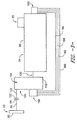
FIG. 3 is a schematic view of various components of a work vehicle and transmission thereof, including a main transmission body, dropbox, main pump and auxiliary pump in accordance with one embodiment of the present disclosure; -
FIG. 4 is a perspective view of a dropbox assembly and an engine flywheel (shown exploded from the dropbox assembly) in accordance with one embodiment of the present disclosure; -
FIG. 5 is a perspective view of components of a dropbox assembly, with a dropbox housing removed for illustrative purposes, in accordance with one embodiment of the present disclosure; -
FIG. 6 is a perspective exploded view of a pump shaft and output shaft in accordance with one embodiment of the present disclosure; -
FIG. 7 is a cross-sectional view of an output shaft in accordance with one embodiment of the present disclosure; -
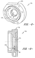
FIG. 8 is a perspective view of a cover in accordance with one embodiment of the present disclosure; and -
FIG. 9 is a cross-sectional view of a cover in accordance with one embodiment of the present disclosure. - Reference now will be made in detail to embodiments of the invention, one or more examples of which are illustrated in the drawings. Each example is provided by way of explanation of the invention, not limitation of the invention. In fact, it will be apparent to those skilled in the art that various modifications and variations can be made in the present invention without departing from the scope or spirit of the invention. For instance, features illustrated or described as part of one embodiment can be used with another embodiment to yield a still further embodiment. Thus, it is intended that the present invention covers such modifications and variations as come within the scope of the appended claims and their equivalents.
- Referring now to the drawings,
FIG. 1 illustrates a side view of one embodiment of awork vehicle 10. As shown, thework vehicle 10 is configured as an agricultural tractor. However, in other embodiments, thework vehicle 10 may be configured as any other suitable work vehicle known in the art, such as various other agricultural vehicles, earth-moving vehicles, loaders and/or various other off-road vehicles. - As shown in
FIG. 1 , thework vehicle 10 includes a pair offront wheels 12, a pair orrear wheels 14 and achassis 16 coupled to and supported by thewheels cab 18 may be supported by a portion of thechassis 16 and may house various control orinput devices work vehicle 10. For instance, as shown inFIG. 1 , thework vehicle 10 may include a Forward-Neutral-Reverse-Park (FNRP) lever 20 and aclutch pedal 21. In addition, thework vehicle 10 may include adisplay panel 22 for displaying message windows and/or alerts to the operator and/or for allowing the operator to interface with the vehicle's controller. For instance, in one embodiment, thedisplay panel 22 may include a touch screen and/or associated buttons or other input devices that allow the operator to provide user inputs to the controller. - Moreover, the
work vehicle 10 may include anengine 23 and atransmission 24 mounted on thechassis 16. Thetransmission 24 may be operably coupled to theengine 23 and may provide variably adjusted gear ratios for transferring engine power to thewheels 14 via an axle/differential 26. Theengine 23,transmission 24, and axle/differential 26 may collectively define adrivetrain 28 of thework vehicle 10. - It should be appreciated that the configuration of the
work vehicle 10 described above and shown inFIG. 1 is provided only to place the present subject matter in an exemplary field of use. Thus, it should be appreciated that the present subject matter may be readily adaptable to any manner of work vehicle configuration. For example, in an alternative embodiment, a separate frame or chassis may be provided to which theengine 23,transmission 24, anddifferential 26 are coupled, a configuration common in smaller tractors. Still other configurations may use an articulated chassis to steer thework vehicle 10, or rely on tracks in lieu of thewheels work vehicle 10 may also be configured to be operably coupled to any suitable type of work implement, such as a trailer, spray boom, manure tank, feed grinder, plow and/or the like. - Referring now to
FIG. 2 , a schematic diagram of one embodiment of a continuouslyvariable transmission 24 suitable for use with thework vehicle 10 described above is illustrated in accordance with aspects of the present subject matter. As shown, thetransmission 24 may include ahydrostatic power unit 30 and aplanetary power unit 32. Thehydrostatic power unit 30 and theplanetary power unit 32 may be coupled to a driveline including arange gear set 34 and may also be coupled to a load L. For example, in one embodiment, the load L may correspond to the drive wheels of the work vehicle 10 (e.g., the front and/orrear wheels hydrostatic power unit 30 and theplanetary power unit 32 may be coupled to any other suitable load L, such as loads that include a track drive or a separate operating system of thework vehicle 10. - The
hydrostatic power unit 30 of thetransmission 10 may generally include afluid pump 36 coupled byfluid conduits 38 in a closed loop to afluid motor 40. Themotor 40 may be coupled to theengine 23 via an input gear N6. Specifically, as shown inFIG. 2 , power may be transmitted to thehydrostatic power unit 30 by a driven gear N4 mounted on aforward shaft 42 of thetransmission 10 and engaged with the input gear N6. In addition, an output gear N10 for thehydrostatic power unit 30 may be connected to a ring gear NR of theplanetary power unit 32 via gears N11 and N12. A power take off (PTO) of thevehicle 10 may also be coupled to theengine 23 through the forward shaft 42 (e.g., by coupling a PTO gear reduction N26 to theforward shaft 42, which is coupled to theengine 23 via gears N5 and N1. - In general, the
pump 36 may comprise any suitable electronically controlled pump known in the art, such as an electronically controlled variable displacement hydraulic pump. As such, operation of thepump 36 may be automatically controlled using anelectronic controller 44 of thework machine 10. For example, as shown inFIG. 2 , thecontroller 44 may be communicatively coupled to thepump 36 via a suitablecommunicative link 46 so that the angle of a swash plate of the pump 36 (the swash plate being denoted by adiagonal arrow 48 through pump 36) may be adjusted through a range of positions, thereby adjusting the transmission ratio of thetransmission 24. - It should be appreciated the
controller 44 may generally comprise any suitable processor-based device known in the art. Thus, in several embodiments, thecontroller 44 may include one or more processor(s) and associated memory device(s) configured to perform a variety of computer-implemented functions. As used herein, the term "processor" refers not only to integrated circuits referred to in the art as being included in a computer, but also refers to a controller, a microcontroller, a microcomputer, a programmable logic controller (PLC), an application specific integrated circuit, and other programmable circuits. Additionally, the memory device(s) of thecontroller 44 may generally comprise memory element(s) including, but are not limited to, computer readable medium (e.g., random access memory (RAM)), computer readable non-volatile medium (e.g., a flash memory), a floppy disk, a compact disc-read only memory (CD-ROM), a magneto-optical disk (MOD), a digital versatile disc (DVD) and/or other suitable memory elements. Such memory device(s) may generally be configured to store suitable computer-readable instructions that, when implemented by the processor(s), configure thecontroller 44 to perform various computer-implemented functions, such as the method 200 described below with reference toFIG. 6 . In addition, thecontroller 44 may also include various other suitable components, such as a communications circuit or module, one or more input/output channels, a data/control bus and/or the like. - Referring still to
FIG. 2 , theplanetary power unit 32 of thetransmission 24 may generally include a primary sun gear NS1 mounted on aplanetary input shaft 50. As shown, theplanetary input shaft 50 may be coupled to theengine 23 via a forward directional clutch 52 or a reverse directional clutch 54. In addition, theplanetary power unit 32 may be configured to be selectively coupled to the load L, coupled to thehydrostatic power unit 30 and selectively coupled to theengine 23, all under automatic control of thecontroller 44. For example, for coupling theplanetary power unit 32 to the load L, thetransmission 24 may include anoutput shaft 56 coupled to the load L which carries an input gear N18 engaged with an output gear N17 on arange 1/2shaft 58 of the range gear set 34 and a gear N22 engaged with a gear N19 on a range 3/4shaft 60 of the range gear set 34. Therange 1/2shaft 58 may, in turn, be coupled to theplanetary power unit 32 via automatic operation of range selectors or clutches R1 and R2 for power flow through gears N13 and N14, or N15 and N16, respectively. Similarly, the range 3/4shaft 60 may be coupled to theplanetary power unit 32 via range selectors or clutches R3 and R4 for power flow via gears N13 and N20, or N15 and N21, respectively. Therange 1/2 and 3/4shafts planetary power unit 32 to provide dual power flow. It should be appreciated that operation of the various clutches (e.g., the forward directional clutch 52, the reverse directional clutch 54, and clutches R1, R2, R3 and R4) may be automatically controlled by thecontroller 44 using suitable hydraulic actuators 62 (e.g., hydraulic pistons). Specifically, as will be described below, thecontroller 44 may be communicatively coupled to corresponding clutch control valves configured to control the supply of hydraulic fluid to eachhydraulic actuator 62. - The
controller 44 may also be communicatively coupled to aswash plate actuator 64 for automatically controlling the position or angle of theswash plate 48 of thepump 36. For example, theactuator 64 may be configured to move theswash plate 48 across a range of angles in response to control signals (e.g., current commands) received from thecontroller 44. In addition, thecontroller 44 may be coupled to any number of sensors for monitoring the various operating parameters of thetransmission 24 including, but not limited to, pressure transducers orsensors 66 for sensing the pressure within theconduits 38 connecting thepump 36 to themotor 40 and/or for sensing the pressure of the hydraulic fluid supplied to each clutch of the transmission 24 (e.g., as will be described below with reference toFIG. 3 ),speed sensors 67 for sensing the output speed of thetransmission 24, the speed(s) of the various clutches (and/or clutch cans) of thetransmission 24 and/or the motor speed of thefluid motor 40,swashplate sensors 68 for monitoring the angle of theswashplate 48 and/or any other suitable sensors. Similarly, thecontroller 44 may also be connected to the engine 23 (e.g., a speed governor of the engine 23) for receiving engine speed data and other information therefrom. - Additionally, as shown in
FIG. 2 , thecontroller 44 may also be communicatively coupled to the operator-controlled input device(s) 20, 21, 22 positioned within thecab 18 via a suitablecommunicative link 46. For example, thecontroller 44 may be coupled to theFRNP lever 20, theclutch pedal 21, thedisplay panel 22 and/or any other suitable input device of the vehicle 10 (e.g., the speed control lever or pedal, the engine throttle lever, the neutral button and/or any other suitable lever, pedal, button or control panel of the vehicle 10). - During operation, the
transmission 24 may be operated to have a combined hydrostatic and mechanical power flow by engaging the reverse directional clutch 54 to the powerplanetary power unit 32 via gears N1, N3, N5 and N7, or engaging the forward directional clutch 52 to power the powerplanetary power unit 32 via gears N1, N8, and N2. Alternatively, thetransmission 44 may be operated to have a pure hydrostatic power flow by disengaging both of thedirectional clutches transmission 24 may provide a seamless transition between ranges to provide work/road configurations as desired. In particular, speed changes from zero to the maximum speed within each speed range of thetransmission 24 may be achieved in a smooth and continuous manner by automatically changing the swash plate angle of thepump 36 via control signals transmitted from thecontroller 44. For each speed range, substantially the full range of travel of the swash plate may be used. For example, in several embodiments, theswash plate 48 may be at one end of its range of travel for zero speed within a specific speed range, may be at the other end of its range of travel for the maximum speed of that speed range and may be at a zero tilt or neutral position within its range of travel for an intermediate speed of that same speed range. - Referring still to
FIG. 2 , thetransmission 24 may also include a parking brake 70 operably positioned on theload shaft 56. In several embodiments, the parking brake 70 may be communicatively coupled to the controller 44 (via a suitable communicative link 46) for automatic control thereof. For example, thecontroller 44 may be configured to proportionally or gradually engage the parking brake 70 as well as gradually release or disengage the parking brake 70. In such embodiments, the pressure of the hydraulic fluid supplied to the parking brake 70 may be controlled using an automatic valve (e.g., a proportional pressure reducing valve) configured to be operated via control signals transmitted from thecontroller 44. As is generally understood, the parking brake pressure may be inversely related to the parking brake torque. Thus, contrary to the various clutches of thetransmission 24, the parking brake 70 may be designed such that it is engaged when the pressure within the brake 70 is reduced and disengaged when the pressure within the brake 70 is increased. - In addition, for operation when the
controller 44 is not powered or is not properly functioning, the parking brake 70 may also be configured to be engaged using a separate means. For instance, the parking brake 70 may be spring applied or may include any other suitable biasing means configured to bias the parking brake 70 into engagement. Alternatively, the parking brake 70 may include a suitable mechanical means for engaging the brake 70 when thecontroller 44 is not powered or is not properly functioning. Moreover, a means may be provided to store pressurized hydraulic fluid in the event theengine 23 stalls so that the parking brake 70 may remain released and/or may be applied and released several times if needed to control thevehicle 10 until theengine 23 can be restarted. Additionally, other means (e.g., a hand pump) may be provided to disengage the parking brake 70 if there is a fault and no stored pressurized hydraulic fluid is left within the system. - It should be appreciated that the configuration of the
transmission 24 shown inFIG. 2 simply illustrates one example of a suitable transmission with which the disclosed system and method may be utilized. Thus, one of ordinary skill in the art should appreciate that application of the present subject matter need not be limited to the particular CVT configuration shown inFIG. 2 , but, rather, the present subject matter may be advantageously used with various different CVT configurations. Similarly, it should be appreciated that the present subject matter need not be limited to applications within CVTs. For example, the disclosed system and method may also be advantageously utilized with a power shift transmission (PST) or in any other suitable transmission. - Referring now to
FIGS. 3 through 9 , various embodiments oftransmissions 24 anddropbox assemblies 100 are disclosed.Transmission 24 in general may be any suitable transmission, including CVTs and PSTs as discussed above. Adropbox assembly 100 may be a component of thetransmission 24. As shown inFIG. 3 ,transmission 24 may include amain transmission body 80 which houses various components of thetransmission 24, such as various gears, shafts, etc. discussed above. Amain pump 85 may additionally be included intransmission 24, and may for example be mounted to themain transmission body 80.Main pump 85 may, for example, correspond to pump 36 ofFIG. 2 .Dropbox assembly 100 may include adropbox housing 102 which additionally houses various gears, shafts, etc. of the transmission. In particular, thedropbox housing 102 houses agear assembly 110 which includes gears which initially transmit rotational power from theengine 23 to the rest of thetransmission 24. - For example,
gear assembly 110 may include aninput gear 112 and anoutput gear 114, each of which may includegear teeth gear assembly 110 further includes anidler gear 116 disposed between theinput gear 112 andoutput gear 114.Gear teeth 117 of theidler gear 116 may mesh with theteeth 113 andteeth 115 to transmit rotational power between theinput gear 112 andoutput gear 114. In other embodiments, however, theinput gear 112 andoutput gear 114 may directly mesh, or other intermediate gears may be included between theinput gear 112 andoutput gear 114. - Notably, and referring briefly again to
FIG. 2 , thegears FIG. 2 . In any case, thegear assembly 110 includes the initial gears that receive output rotational power from theengine 23, and specifically theflywheel 90 thereof, and which transmit this rotational power to the remainder of thetransmission 24. -
Flywheel 90 ofengine 23 may be coupled to anengine output shaft 92 which is rotatable with theflywheel 90. The rotational power from theengine 23 may be transmitted through thisshaft 92 to thegear assembly 110. For example, aninput shaft 120 may be coupled to theinput gear 112, such as via outer splines of theshaft 120 and inner splines of thegear 112 as is generally understood. Theinput shaft 120 may be connected to theoutput shaft 92, such as viaflanges output shaft 92 may also serve as theinput shaft 120. In any event, rotation of theflywheel 90 may cause rotation of theinput shaft 120. - Referring now to
FIGS. 4 and5 ,dropbox housing 102 may define an interior 104 in whichgear assembly 110 may be disposed.Input shaft 120 may extend through thedropbox housing 102 to be coupled toinput gear 112.Input gear 112 may be coupled to and rotatable with theinput shaft 120, and may thus drive thegear assembly 110. -
Dropbox assembly 100 may further include anoutput shaft 130. Theoutput shaft 130 may be coupled to and rotatable with theoutput gear 114, and may thus transmit the rotational power from theengine 23 as transmitted through thegear assembly 110 to the remainder of thetransmission 24. - Further,
dropbox assembly 100 may include apump 150, which in exemplary embodiments is anauxiliary pump 150 provided in addition tomain pump 85. Thepump 150 may be mounted to thedropbox housing 102, as discussed herein. Pump 150 may include, as shown, apump housing 152 and apump shaft 154. As discussed herein, thepump housing 152 may be disposed exterior todropbox housing 102, and thepump shaft 154 may be coupled to and rotatable with theoutput shaft 130. Forexample pump shaft 154 oroutput shaft 130 may extend throughdropbox housing 102 to facilitate such coupling. - Use of a
pump 150 in accordance with the present disclosure may advantageously provide additional hydraulic power for use as required bywork vehicle 10. For example, the additional hydraulic power provided bypump 150 can advantageously be utilized to power add-ons such as planters or seeders. Further, mounting of thepump 150 to thedropbox housing 102 advantageously locates thepump 150 in a convenient, easy to access and install (during production) location, thus facilitating efficient and cost-effective modification of thetransmission 23. Still further such mounting of thepump 150 advantageously allows thepump 150 to be driven byoutput shaft 130, thus utilizing the existing rotational power transmission structure. - Referring now to
FIGS. 5 through 9 , various embodiments of components ofdropbox assembly 100 as illustrated. For example, as shown,output shaft 130 includes abody 132 which has aninner surface 134 andouter surface 135 and which extends between afirst end 136 and asecond end 137, such as along a longitudinal orrotational axis 138. Further, thebody 132 may define abore 140 which extends into thebody 132 from thefirst end 136 and which defines theinner surface 134.Output shaft 130 may further include various pluralities of splines extending from the surfaces of thebody 132 to couple theshaft 130 to other rotational components. For example, a first plurality ofouter splines 142 extending from theouter surface 135 may couple theoutput shaft 130 to inner splines (not shown) of theoutput gear 114. Thesesplines 142 may be disposed proximatefirst end 136. A second plurality ofouter spines 144 extending from theouter surface 135 may couple theoutput shaft 130 to inner splines of a suitable downstream (in the direction of power transmission from the engine 23) gear, shaft, etc. oftransmission 24. Thesesplines 144 may be disposed proximatesecond end 137. Further, a plurality ofinner splines 146 may extend from theinner surface 134, such as proximatefirst end 136. Thesesplines 146 may couple theoutput shaft 130 to thepump shaft 154. - For example,
pump shaft 154 may have abody 162 which includes anouter surface 163 that extends between afirst end 164 and asecond end 165, such as along a longitudinal or rotational axis 166 (which may be coaxial withaxis 138 when theshafts splines 168 may extend from theouter surface 163, such as proximate thesecond end 165. Thesecond end 165 may extend into thebore 140 of theoutput shaft 130 such that theouter splines 168 mesh with theinner splines 146, thus coupling theshafts - It should be understood that the present disclosure is not limited to
output shaft 130 havinginner splines 146 andpump shaft 154 havingouter splines 168 for such coupling. In other embodiments,output shaft 130 may have additional outer splines andpump shaft 154 may have corresponding inner splines. Still further, any suitable coupling ofshafts - Output shaft130 may further include one or more lubrication passages defined in the
body 132 for flowing a lubricant, such as oil, therethrough. This may allow the lubricant to lubricate theoutput shaft 130 and other components of thedropbox assembly 100 andtransmission 24. For example, afirst lubrication passage 148 may be defined in thebody 132. Thispassage 148 may extend from thebore 140 towards thesecond end 137, such as alongaxis 138. Asecond lubrication passage 149 may additionally be defined in thebody 132, and may be in fluid communication with thefirst lubrication passage 148. Thesecond lubrication passage 149 may, for example, extend between theouter surface 135 and thefirst lubrication passage 148, such as transverse to theaxis 138. - As discussed, pump 150 may be mounted to
dropbox housing 102. For example, in some embodiments, pumphousing 152 may be directly connected to thedropbox housing 102, such as through the use of suitable mechanical fasteners (i.e. nut/bolt combinations, screws, nails, rivets, etc.). In other embodiments as shown, acover 170 may be positioned between thepump housing 152 and thedropbox housing 102. Thepump housing 152 may be connected to thecover 170, and cover 170 may be connected todropbox housing 102, such as each through the use of suitable mechanical fasteners. Cover 170 may include abody 172 which defines ashaft aperture 174. The output shaft 130 (as shown) or thepump shaft 154 may extend through theshaft aperture 174 to facilitate coupling of thepump shaft 154 andoutput shaft 130. - Cover 170 may further include one or more lubrication passages defined in the
body 172 for flowing a lubricant, such as oil, therethrough. This may allow the lubricant to lubricate components of thedropbox assembly 100 andtransmission 24. For example, afirst lubrication passage 176 may be defined in thebody 172, and asecond lubrication passage 178 may be defined in thebody 172 in fluid communication with and transverse to thefirst lubrication passage 176. When assembled,second lubrication passage 178 may extend generally parallel toaxes interior 104. - Referring again briefly to
FIG. 3 , as discussed, pump 150 may provide hydraulic power (which may be supplemental hydraulic power) forvehicle 10. Accordingly, pump 150 may further include various fluid lines extending from thepump housing 152. For example, asupply line 180,return line 182,drain line 184, andload sensing line 186 may all extend frompump housing 152, as may be generally understood. Further, pump 150 may include a manifold 190 which may connect to various other components ofwork vehicle 10, such as for example add-on components as discussed herein, for supplying hydraulic fluid to these components. Manifold may, for example, be mounted to themain transmission body 80. Various of the fluid lines, such assupply line 180,return line 182,drain line 184 and/orload sensing line 186, may be in fluid communication withmanifold 190 and thus extend betweenpump housing 152 andmanifold 190. - This written description uses examples to disclose the invention, including the best mode, and also to enable any person skilled in the art to practice the invention, including making and using any devices or systems and performing any incorporated methods. The patentable scope of the invention is defined by the claims, and may include other examples that occur to those skilled in the art. Such other examples are intended to be within the scope of the claims if they include structural elements that do not differ from the literal language of the claims, or if they include equivalent structural elements with insubstantial differences from the literal languages of the claims.
Claims (11)
- A dropbox assembly (100) for a transmission (24) of a work vehicle (10), the dropbox assembly (100) comprising:- a dropbox housing (102) defining an interior (104);- a gear assembly (110) disposed within the interior (104) of the dropbox housing (102), the gear assembly (110) comprising an input gear (112) and an output gear (114);- an output shaft (130) coupled to and rotatable with the output gear (114) ; and- a pump (150) mounted to the dropbox housing (102), the pump (150) comprising a pump housing (152) disposed exterior to the dropbox housing (102) and a pump shaft (154), the pump shaft (154) coupled to and rotatable with the output shaft (130).
- The dropbox assembly (100) of claim 1, wherein the output shaft (130) comprises a body (132) having an inner surface (134) and an outer surface (135) and extending between a first end (136) and a second end (137), the body (132) defining a bore (140) extending into the body (132) from the first end (136), the bore (140) defining the inner surface (134), the output shaft (130) further comprising a plurality of outer splines (142, 144) extending from the outer surface (135) and a plurality of inner splines (146) extending from the inner surface (134).
- The dropbox assembly (100) of claim 2, wherein the pump shaft (154) comprises a body (162) having an outer surface (163) and extending between a first end (164) and a second end (165), the pump shaft (154) further comprising a plurality of outer splines (168) extending from the outer surface (163), the outer splines (168) meshed with the inner splines (146) of the output shaft (130).
- The dropbox assembly (100) of claim 2, wherein the output shaft (130) further comprises at least one lubrication passage (148, 149) defined in the body (132).
- The dropbox assembly (100) of claim 4, wherein the at least one lubrication passage (148, 149) is a plurality of lubrication passages (148, 149), the plurality of lubrication passages (148, 149) comprising a first lubrication passage (148) and a second lubrication passage (149), the first lubrication passage (149) defined in the body (132) and extending from the bore (140) towards the second end (137), the second lubrication passage (149) defined in the body (132) and extending between the outer surface (135) and the first lubrication passage (148).
- The dropbox assembly (100) of claim 1, wherein the gear assembly (110) further comprises an idler gear (116) disposed between the input gear (112) and output gear (114).
- The dropbox assembly (100) of claim 1, further comprising a cover (170) positioned between the pump housing (152) and the dropbox housing (102), the cover (170) comprising a body (172) defining a shaft aperture (168), the output shaft (130) extending through the shaft aperture (168), the pump housing (152) connected to the cover (170).
- The dropbox assembly (100) of claim 7, wherein the cover (170) further comprises at least one lubrication passage (176, 178) defined in the body (172).
- A transmission (24) for a work vehicle (10), the transmission (24) comprising:- an input shaft (120);- a dropbox assembly (100) according to any of the preceding claims.
- The transmission of claim 9, wherein the pump (150) further comprises a manifold (190) and at least one fluid line (180, 182, 184, 186) extending between the pump housing (152) and the manifold (190).
- The transmission of claim 10, wherein the manifold (190) is mounted to a main transmission body (80).
Applications Claiming Priority (1)
| Application Number | Priority Date | Filing Date | Title |
|---|---|---|---|
| US14/712,971 US9975424B2 (en) | 2015-05-15 | 2015-05-15 | Dropbox assembly for transmission of work vehicle |
Publications (3)
| Publication Number | Publication Date |
|---|---|
| EP3093180A2 true EP3093180A2 (en) | 2016-11-16 |
| EP3093180A3 EP3093180A3 (en) | 2017-03-08 |
| EP3093180B1 EP3093180B1 (en) | 2019-08-28 |
Family
ID=56008536
Family Applications (1)
| Application Number | Title | Priority Date | Filing Date |
|---|---|---|---|
| EP16169904.6A Active EP3093180B1 (en) | 2015-05-15 | 2016-05-17 | Dropbox assembly for transmission of work vehicle |
Country Status (4)
| Country | Link |
|---|---|
| US (1) | US9975424B2 (en) |
| EP (1) | EP3093180B1 (en) |
| CN (1) | CN106151460A (en) |
| BR (1) | BR102016008463B1 (en) |
Cited By (1)
| Publication number | Priority date | Publication date | Assignee | Title |
|---|---|---|---|---|
| CN115234626A (en) * | 2022-07-04 | 2022-10-25 | 潍柴动力股份有限公司 | Mechanical hydraulic power split type stepless speed change transmission system |
Families Citing this family (4)
| Publication number | Priority date | Publication date | Assignee | Title |
|---|---|---|---|---|
| EP3037692B1 (en) * | 2014-12-23 | 2018-02-07 | NAF Neunkirchener Achsenfabrik AG | Power split drive for a motor vehicle |
| US10190662B2 (en) * | 2016-07-19 | 2019-01-29 | Deere & Company | Variator for work vehicle drivetrain |
| US10569776B2 (en) * | 2017-12-04 | 2020-02-25 | Deere & Company | Hydraulic control system |
| US12351019B1 (en) * | 2024-07-03 | 2025-07-08 | Caterpillar Inc. | Retainer for power take-off assembly |
Family Cites Families (31)
| Publication number | Priority date | Publication date | Assignee | Title |
|---|---|---|---|---|
| US4019404A (en) | 1975-03-21 | 1977-04-26 | Sundstrand Corporation | Power transmission |
| DE2515048C3 (en) | 1975-04-07 | 1982-02-18 | M.A.N. Maschinenfabrik Augsburg-Nuernberg Ag, 8000 Muenchen | Drive arrangement with energy storage, in particular for road vehicles |
| US4121479A (en) | 1977-03-04 | 1978-10-24 | Sundstrand Corporation | Power transmission |
| GB2308164B (en) | 1995-12-14 | 1999-03-17 | Caterpillar Inc | Caseless transmission structure |
| DE19605386C1 (en) | 1996-02-14 | 1997-06-12 | Gottfried Keller | Hydrostatic coupling gear especially for tractors etc. |
| SE507362C2 (en) | 1996-09-23 | 1998-05-18 | Volvo Lastvagnar Ab | Drive device for a servo pump and gearbox for a vehicle |
| JPH11286220A (en) | 1998-02-10 | 1999-10-19 | Dana Corp | Motor vehicle torque transfer case pump drive device |
| US6090005A (en) | 1999-07-26 | 2000-07-18 | General Motors Corporation | Two-mode, compound-split, vehicular transmission having both enhanced speed and enhanced tractive power |
| US6457560B1 (en) | 2000-08-21 | 2002-10-01 | Magic Circle Corporation | Gear box oil pumping system |
| SE519741C2 (en) | 2000-09-11 | 2003-04-01 | Volvo Constr Equip Components | Device for positioning a connector |
| US7174998B2 (en) | 2001-10-15 | 2007-02-13 | Borgwarner Inc. | Submerged electric fluid pump |
| US8092202B2 (en) | 2005-06-07 | 2012-01-10 | Hamilton Sundstrand Corporation | Propeller pump system for handed propeller applications |
| US8050827B2 (en) * | 2005-07-20 | 2011-11-01 | Kanzaki Kokyukoki Mfg. Co., Ltd. | Vehicle transmission system |
| US20070144283A1 (en) * | 2005-11-30 | 2007-06-28 | Toshiyuki Hasegawa | Power Transmission Apparatus |
| WO2008151527A1 (en) | 2007-06-11 | 2008-12-18 | Hongjian Zhao | Mechanical-hydraulic combined transmission device |
| US7600769B2 (en) * | 2007-09-10 | 2009-10-13 | Kubota Corporation | Frame structure for work vehicle |
| JP5016421B2 (en) * | 2007-09-10 | 2012-09-05 | 株式会社クボタ | Work vehicle transmission structure |
| US8647225B2 (en) | 2007-11-29 | 2014-02-11 | Ford Global Technologies, Llc | Transfer case for a motor vehicle powertrain |
| EP2244920B2 (en) | 2008-01-22 | 2023-09-27 | Volvo Construction Equipment AB | A method and system for braking a vehicle |
| CN102459844A (en) | 2009-06-09 | 2012-05-16 | 麦格纳动力系有限公司 | Dual power input fluid pump |
| US8862349B2 (en) | 2010-03-09 | 2014-10-14 | Allison Transmission, Inc. | Integrated transmission and auxiliary gearbox control |
| CN202032044U (en) * | 2011-04-28 | 2011-11-09 | 杭州前进齿轮箱集团股份有限公司 | Speed reduction transfer case |
| ES2452554T3 (en) | 2011-08-30 | 2014-04-01 | Siemens Aktiengesellschaft | Gear series |
| CN202327034U (en) * | 2011-11-16 | 2012-07-11 | 重庆齿轮箱有限责任公司 | Bearing cooling and lubricating structure for high-speed shaft at output end of transfer case |
| JP2013119918A (en) | 2011-12-08 | 2013-06-17 | Aisin Seiki Co Ltd | Power transmission device |
| US20130323015A1 (en) | 2012-05-31 | 2013-12-05 | Dana Heavy Vehicle Systems Group, Llc | Power Distribution Unit With A Forced Lubrication Flow Assembly |
| EP2677210B1 (en) | 2012-06-19 | 2016-04-20 | Turner Powertrain Systems Limited | Gearbox hydraulic circuit |
| US20150167820A1 (en) | 2012-07-09 | 2015-06-18 | Volvo Lastvagnar Ab | Transmission with an oil pump |
| US10780853B2 (en) | 2012-10-01 | 2020-09-22 | Allison Transmission, Inc. | External lube system for a transmission |
| US8888658B2 (en) | 2012-10-31 | 2014-11-18 | Borgwarner, Inc. | Transfer case utilizing an on-demand centrifugally governed hydraulic power supply to perform both range shift and on-demand four wheel drive |
| JP2015171880A (en) * | 2014-02-21 | 2015-10-01 | 株式会社 神崎高級工機製作所 | Transmission for work vehicle |
-
2015
- 2015-05-15 US US14/712,971 patent/US9975424B2/en active Active
-
2016
- 2016-03-31 CN CN201610194441.9A patent/CN106151460A/en active Pending
- 2016-04-15 BR BR102016008463-6A patent/BR102016008463B1/en not_active IP Right Cessation
- 2016-05-17 EP EP16169904.6A patent/EP3093180B1/en active Active
Non-Patent Citations (1)
| Title |
|---|
| None |
Cited By (1)
| Publication number | Priority date | Publication date | Assignee | Title |
|---|---|---|---|---|
| CN115234626A (en) * | 2022-07-04 | 2022-10-25 | 潍柴动力股份有限公司 | Mechanical hydraulic power split type stepless speed change transmission system |
Also Published As
| Publication number | Publication date |
|---|---|
| CN106151460A (en) | 2016-11-23 |
| US9975424B2 (en) | 2018-05-22 |
| US20160332515A1 (en) | 2016-11-17 |
| EP3093180A3 (en) | 2017-03-08 |
| EP3093180B1 (en) | 2019-08-28 |
| BR102016008463B1 (en) | 2022-12-20 |
| BR102016008463A2 (en) | 2016-11-16 |
Similar Documents
| Publication | Publication Date | Title |
|---|---|---|
| EP3093180B1 (en) | Dropbox assembly for transmission of work vehicle | |
| EP2872370B1 (en) | System and method for controlling rollback of a work vehicle | |
| EP2930391B1 (en) | System and method for automatically calibrating the clutches within a transmission of a work vehicle | |
| US7121970B2 (en) | Control system for a hydro-mechanical transmission | |
| EP2934977B1 (en) | System and method for reducing fuel consumption of a work vehicle | |
| CN111075902B (en) | Transmission structure and work vehicle | |
| US9423026B2 (en) | System and method for controlling a continuously variable transmission when transitioning operation from a hydrostatic mode to a hydro-mechanical mode | |
| CN105402397B (en) | Electronic transmission range for automatic transmission selects subsystem | |
| US11293528B2 (en) | Working vehicle | |
| US10427670B2 (en) | Supplemental hydraulic motor for continuously variable transmission | |
| DE102008051458A1 (en) | Transfer case for a motor vehicle powertrain | |
| EP2865923B1 (en) | System and method for enhancing the operation of a continuously variable transmission of a work vehicle | |
| US9874279B1 (en) | System and method for operating a continuously variable transmission of a work vehicle in a hydrostatic bypass mode | |
| EP3032124B1 (en) | System and method for preventing centrifugal clutch lock-ups within a transmission of a work vehicle | |
| CN104691321A (en) | Two-gear hydraulic driving bridge assembly for large grain combine harvester | |
| JP2002098217A (en) | Hydraulic and mechanical stepless transmission | |
| JP4695521B2 (en) | Working gear shifting structure | |
| JP4585537B2 (en) | Tractor transmission structure | |
| JPS5925694Y2 (en) | Agricultural tractor PTO device lubrication mechanism | |
| JPH09240297A (en) | Travel transmission structure of work vehicle | |
| JPS6223629Y2 (en) | ||
| JP5186032B2 (en) | Working gear shifting structure | |
| JP2007191022A (en) | Auxiliary speed change mechanism of tractor | |
| JP2004066859A (en) | Harvester drive structure | |
| JPH0247630B2 (en) |
Legal Events
| Date | Code | Title | Description |
|---|---|---|---|
| PUAI | Public reference made under article 153(3) epc to a published international application that has entered the european phase |
Free format text: ORIGINAL CODE: 0009012 |
|
| AK | Designated contracting states |
Kind code of ref document: A2 Designated state(s): AL AT BE BG CH CY CZ DE DK EE ES FI FR GB GR HR HU IE IS IT LI LT LU LV MC MK MT NL NO PL PT RO RS SE SI SK SM TR |
|
| AX | Request for extension of the european patent |
Extension state: BA ME |
|
| PUAL | Search report despatched |
Free format text: ORIGINAL CODE: 0009013 |
|
| AK | Designated contracting states |
Kind code of ref document: A3 Designated state(s): AL AT BE BG CH CY CZ DE DK EE ES FI FR GB GR HR HU IE IS IT LI LT LU LV MC MK MT NL NO PL PT RO RS SE SI SK SM TR |
|
| AX | Request for extension of the european patent |
Extension state: BA ME |
|
| RIC1 | Information provided on ipc code assigned before grant |
Ipc: F16H 57/031 20120101ALI20170201BHEP Ipc: F16H 61/00 20060101ALI20170201BHEP Ipc: F16H 57/04 20100101ALI20170201BHEP Ipc: F16H 57/02 20120101ALI20170201BHEP Ipc: B60K 17/28 20060101AFI20170201BHEP Ipc: B60K 25/02 20060101ALI20170201BHEP |
|
| STAA | Information on the status of an ep patent application or granted ep patent |
Free format text: STATUS: REQUEST FOR EXAMINATION WAS MADE |
|
| 17P | Request for examination filed |
Effective date: 20170908 |
|
| RBV | Designated contracting states (corrected) |
Designated state(s): AL AT BE BG CH CY CZ DE DK EE ES FI FR GB GR HR HU IE IS IT LI LT LU LV MC MK MT NL NO PL PT RO RS SE SI SK SM TR |
|
| STAA | Information on the status of an ep patent application or granted ep patent |
Free format text: STATUS: EXAMINATION IS IN PROGRESS |
|
| 17Q | First examination report despatched |
Effective date: 20180627 |
|
| GRAP | Despatch of communication of intention to grant a patent |
Free format text: ORIGINAL CODE: EPIDOSNIGR1 |
|
| STAA | Information on the status of an ep patent application or granted ep patent |
Free format text: STATUS: GRANT OF PATENT IS INTENDED |
|
| INTG | Intention to grant announced |
Effective date: 20190320 |
|
| GRAS | Grant fee paid |
Free format text: ORIGINAL CODE: EPIDOSNIGR3 |
|
| GRAA | (expected) grant |
Free format text: ORIGINAL CODE: 0009210 |
|
| STAA | Information on the status of an ep patent application or granted ep patent |
Free format text: STATUS: THE PATENT HAS BEEN GRANTED |
|
| AK | Designated contracting states |
Kind code of ref document: B1 Designated state(s): AL AT BE BG CH CY CZ DE DK EE ES FI FR GB GR HR HU IE IS IT LI LT LU LV MC MK MT NL NO PL PT RO RS SE SI SK SM TR |
|
| REG | Reference to a national code |
Ref country code: GB Ref legal event code: FG4D |
|
| REG | Reference to a national code |
Ref country code: CH Ref legal event code: EP |
|
| REG | Reference to a national code |
Ref country code: AT Ref legal event code: REF Ref document number: 1171987 Country of ref document: AT Kind code of ref document: T Effective date: 20190915 |
|
| REG | Reference to a national code |
Ref country code: IE Ref legal event code: FG4D |
|
| REG | Reference to a national code |
Ref country code: DE Ref legal event code: R096 Ref document number: 602016019268 Country of ref document: DE |
|
| REG | Reference to a national code |
Ref country code: NL Ref legal event code: MP Effective date: 20190828 |
|
| REG | Reference to a national code |
Ref country code: LT Ref legal event code: MG4D |
|
| PG25 | Lapsed in a contracting state [announced via postgrant information from national office to epo] |
Ref country code: PT Free format text: LAPSE BECAUSE OF FAILURE TO SUBMIT A TRANSLATION OF THE DESCRIPTION OR TO PAY THE FEE WITHIN THE PRESCRIBED TIME-LIMIT Effective date: 20191230 Ref country code: LT Free format text: LAPSE BECAUSE OF FAILURE TO SUBMIT A TRANSLATION OF THE DESCRIPTION OR TO PAY THE FEE WITHIN THE PRESCRIBED TIME-LIMIT Effective date: 20190828 Ref country code: HR Free format text: LAPSE BECAUSE OF FAILURE TO SUBMIT A TRANSLATION OF THE DESCRIPTION OR TO PAY THE FEE WITHIN THE PRESCRIBED TIME-LIMIT Effective date: 20190828 Ref country code: NL Free format text: LAPSE BECAUSE OF FAILURE TO SUBMIT A TRANSLATION OF THE DESCRIPTION OR TO PAY THE FEE WITHIN THE PRESCRIBED TIME-LIMIT Effective date: 20190828 Ref country code: BG Free format text: LAPSE BECAUSE OF FAILURE TO SUBMIT A TRANSLATION OF THE DESCRIPTION OR TO PAY THE FEE WITHIN THE PRESCRIBED TIME-LIMIT Effective date: 20191128 Ref country code: NO Free format text: LAPSE BECAUSE OF FAILURE TO SUBMIT A TRANSLATION OF THE DESCRIPTION OR TO PAY THE FEE WITHIN THE PRESCRIBED TIME-LIMIT Effective date: 20191128 Ref country code: SE Free format text: LAPSE BECAUSE OF FAILURE TO SUBMIT A TRANSLATION OF THE DESCRIPTION OR TO PAY THE FEE WITHIN THE PRESCRIBED TIME-LIMIT Effective date: 20190828 Ref country code: FI Free format text: LAPSE BECAUSE OF FAILURE TO SUBMIT A TRANSLATION OF THE DESCRIPTION OR TO PAY THE FEE WITHIN THE PRESCRIBED TIME-LIMIT Effective date: 20190828 |
|
| PG25 | Lapsed in a contracting state [announced via postgrant information from national office to epo] |
Ref country code: RS Free format text: LAPSE BECAUSE OF FAILURE TO SUBMIT A TRANSLATION OF THE DESCRIPTION OR TO PAY THE FEE WITHIN THE PRESCRIBED TIME-LIMIT Effective date: 20190828 Ref country code: IS Free format text: LAPSE BECAUSE OF FAILURE TO SUBMIT A TRANSLATION OF THE DESCRIPTION OR TO PAY THE FEE WITHIN THE PRESCRIBED TIME-LIMIT Effective date: 20191228 Ref country code: GR Free format text: LAPSE BECAUSE OF FAILURE TO SUBMIT A TRANSLATION OF THE DESCRIPTION OR TO PAY THE FEE WITHIN THE PRESCRIBED TIME-LIMIT Effective date: 20191129 Ref country code: ES Free format text: LAPSE BECAUSE OF FAILURE TO SUBMIT A TRANSLATION OF THE DESCRIPTION OR TO PAY THE FEE WITHIN THE PRESCRIBED TIME-LIMIT Effective date: 20190828 Ref country code: AL Free format text: LAPSE BECAUSE OF FAILURE TO SUBMIT A TRANSLATION OF THE DESCRIPTION OR TO PAY THE FEE WITHIN THE PRESCRIBED TIME-LIMIT Effective date: 20190828 Ref country code: LV Free format text: LAPSE BECAUSE OF FAILURE TO SUBMIT A TRANSLATION OF THE DESCRIPTION OR TO PAY THE FEE WITHIN THE PRESCRIBED TIME-LIMIT Effective date: 20190828 |
|
| REG | Reference to a national code |
Ref country code: AT Ref legal event code: MK05 Ref document number: 1171987 Country of ref document: AT Kind code of ref document: T Effective date: 20190828 |
|
| PG25 | Lapsed in a contracting state [announced via postgrant information from national office to epo] |
Ref country code: TR Free format text: LAPSE BECAUSE OF FAILURE TO SUBMIT A TRANSLATION OF THE DESCRIPTION OR TO PAY THE FEE WITHIN THE PRESCRIBED TIME-LIMIT Effective date: 20190828 |
|
| PG25 | Lapsed in a contracting state [announced via postgrant information from national office to epo] |
Ref country code: AT Free format text: LAPSE BECAUSE OF FAILURE TO SUBMIT A TRANSLATION OF THE DESCRIPTION OR TO PAY THE FEE WITHIN THE PRESCRIBED TIME-LIMIT Effective date: 20190828 Ref country code: DK Free format text: LAPSE BECAUSE OF FAILURE TO SUBMIT A TRANSLATION OF THE DESCRIPTION OR TO PAY THE FEE WITHIN THE PRESCRIBED TIME-LIMIT Effective date: 20190828 Ref country code: EE Free format text: LAPSE BECAUSE OF FAILURE TO SUBMIT A TRANSLATION OF THE DESCRIPTION OR TO PAY THE FEE WITHIN THE PRESCRIBED TIME-LIMIT Effective date: 20190828 Ref country code: RO Free format text: LAPSE BECAUSE OF FAILURE TO SUBMIT A TRANSLATION OF THE DESCRIPTION OR TO PAY THE FEE WITHIN THE PRESCRIBED TIME-LIMIT Effective date: 20190828 Ref country code: PL Free format text: LAPSE BECAUSE OF FAILURE TO SUBMIT A TRANSLATION OF THE DESCRIPTION OR TO PAY THE FEE WITHIN THE PRESCRIBED TIME-LIMIT Effective date: 20190828 |
|
| PG25 | Lapsed in a contracting state [announced via postgrant information from national office to epo] |
Ref country code: SM Free format text: LAPSE BECAUSE OF FAILURE TO SUBMIT A TRANSLATION OF THE DESCRIPTION OR TO PAY THE FEE WITHIN THE PRESCRIBED TIME-LIMIT Effective date: 20190828 Ref country code: IS Free format text: LAPSE BECAUSE OF FAILURE TO SUBMIT A TRANSLATION OF THE DESCRIPTION OR TO PAY THE FEE WITHIN THE PRESCRIBED TIME-LIMIT Effective date: 20200224 Ref country code: SK Free format text: LAPSE BECAUSE OF FAILURE TO SUBMIT A TRANSLATION OF THE DESCRIPTION OR TO PAY THE FEE WITHIN THE PRESCRIBED TIME-LIMIT Effective date: 20190828 Ref country code: CZ Free format text: LAPSE BECAUSE OF FAILURE TO SUBMIT A TRANSLATION OF THE DESCRIPTION OR TO PAY THE FEE WITHIN THE PRESCRIBED TIME-LIMIT Effective date: 20190828 |
|
| REG | Reference to a national code |
Ref country code: DE Ref legal event code: R097 Ref document number: 602016019268 Country of ref document: DE |
|
| PLBE | No opposition filed within time limit |
Free format text: ORIGINAL CODE: 0009261 |
|
| STAA | Information on the status of an ep patent application or granted ep patent |
Free format text: STATUS: NO OPPOSITION FILED WITHIN TIME LIMIT |
|
| PG2D | Information on lapse in contracting state deleted |
Ref country code: IS |
|
| 26N | No opposition filed |
Effective date: 20200603 |
|
| PG25 | Lapsed in a contracting state [announced via postgrant information from national office to epo] |
Ref country code: SI Free format text: LAPSE BECAUSE OF FAILURE TO SUBMIT A TRANSLATION OF THE DESCRIPTION OR TO PAY THE FEE WITHIN THE PRESCRIBED TIME-LIMIT Effective date: 20190828 |
|
| PG25 | Lapsed in a contracting state [announced via postgrant information from national office to epo] |
Ref country code: LI Free format text: LAPSE BECAUSE OF NON-PAYMENT OF DUE FEES Effective date: 20200531 Ref country code: CH Free format text: LAPSE BECAUSE OF NON-PAYMENT OF DUE FEES Effective date: 20200531 Ref country code: MC Free format text: LAPSE BECAUSE OF FAILURE TO SUBMIT A TRANSLATION OF THE DESCRIPTION OR TO PAY THE FEE WITHIN THE PRESCRIBED TIME-LIMIT Effective date: 20190828 |
|
| REG | Reference to a national code |
Ref country code: BE Ref legal event code: MM Effective date: 20200531 |
|
| PG25 | Lapsed in a contracting state [announced via postgrant information from national office to epo] |
Ref country code: LU Free format text: LAPSE BECAUSE OF NON-PAYMENT OF DUE FEES Effective date: 20200517 |
|
| PG25 | Lapsed in a contracting state [announced via postgrant information from national office to epo] |
Ref country code: IE Free format text: LAPSE BECAUSE OF NON-PAYMENT OF DUE FEES Effective date: 20200517 |
|
| PG25 | Lapsed in a contracting state [announced via postgrant information from national office to epo] |
Ref country code: BE Free format text: LAPSE BECAUSE OF NON-PAYMENT OF DUE FEES Effective date: 20200531 |
|
| PG25 | Lapsed in a contracting state [announced via postgrant information from national office to epo] |
Ref country code: MT Free format text: LAPSE BECAUSE OF FAILURE TO SUBMIT A TRANSLATION OF THE DESCRIPTION OR TO PAY THE FEE WITHIN THE PRESCRIBED TIME-LIMIT Effective date: 20190828 Ref country code: CY Free format text: LAPSE BECAUSE OF FAILURE TO SUBMIT A TRANSLATION OF THE DESCRIPTION OR TO PAY THE FEE WITHIN THE PRESCRIBED TIME-LIMIT Effective date: 20190828 |
|
| PG25 | Lapsed in a contracting state [announced via postgrant information from national office to epo] |
Ref country code: MK Free format text: LAPSE BECAUSE OF FAILURE TO SUBMIT A TRANSLATION OF THE DESCRIPTION OR TO PAY THE FEE WITHIN THE PRESCRIBED TIME-LIMIT Effective date: 20190828 |
|
| PGFP | Annual fee paid to national office [announced via postgrant information from national office to epo] |
Ref country code: DE Payment date: 20250528 Year of fee payment: 10 |
|
| PGFP | Annual fee paid to national office [announced via postgrant information from national office to epo] |
Ref country code: GB Payment date: 20250520 Year of fee payment: 10 |
|
| PGFP | Annual fee paid to national office [announced via postgrant information from national office to epo] |
Ref country code: IT Payment date: 20250522 Year of fee payment: 10 |
|
| PGFP | Annual fee paid to national office [announced via postgrant information from national office to epo] |
Ref country code: FR Payment date: 20250526 Year of fee payment: 10 |