EP3093109A1 - Robot and joint crane work system - Google Patents
Robot and joint crane work system Download PDFInfo
- Publication number
- EP3093109A1 EP3093109A1 EP14875607.5A EP14875607A EP3093109A1 EP 3093109 A1 EP3093109 A1 EP 3093109A1 EP 14875607 A EP14875607 A EP 14875607A EP 3093109 A1 EP3093109 A1 EP 3093109A1
- Authority
- EP
- European Patent Office
- Prior art keywords
- robot
- crane
- section
- workpiece
- suspending unit
- Prior art date
- Legal status (The legal status is an assumption and is not a legal conclusion. Google has not performed a legal analysis and makes no representation as to the accuracy of the status listed.)
- Granted
Links
Images






Classifications
-
- B—PERFORMING OPERATIONS; TRANSPORTING
- B25—HAND TOOLS; PORTABLE POWER-DRIVEN TOOLS; MANIPULATORS
- B25J—MANIPULATORS; CHAMBERS PROVIDED WITH MANIPULATION DEVICES
- B25J9/00—Program-controlled manipulators
- B25J9/16—Program controls
- B25J9/1679—Program controls characterised by the tasks executed
-
- B—PERFORMING OPERATIONS; TRANSPORTING
- B25—HAND TOOLS; PORTABLE POWER-DRIVEN TOOLS; MANIPULATORS
- B25J—MANIPULATORS; CHAMBERS PROVIDED WITH MANIPULATION DEVICES
- B25J19/00—Accessories fitted to manipulators, e.g. for monitoring, for viewing; Safety devices combined with or specially adapted for use in connection with manipulators
- B25J19/02—Sensing devices
- B25J19/021—Optical sensing devices
- B25J19/023—Optical sensing devices including video camera means
-
- B—PERFORMING OPERATIONS; TRANSPORTING
- B66—HOISTING; LIFTING; HAULING
- B66C—CRANES; LOAD-ENGAGING ELEMENTS OR DEVICES FOR CRANES, CAPSTANS, WINCHES, OR TACKLES
- B66C17/00—Overhead travelling cranes comprising one or more substantially horizontal girders the ends of which are directly supported by wheels or rollers running on tracks carried by spaced supports
- B66C17/06—Overhead travelling cranes comprising one or more substantially horizontal girders the ends of which are directly supported by wheels or rollers running on tracks carried by spaced supports specially adapted for particular purposes, e.g. in foundries, forges; combined with auxiliary apparatus serving particular purposes
-
- G—PHYSICS
- G05—CONTROLLING; REGULATING
- G05B—CONTROL OR REGULATING SYSTEMS IN GENERAL; FUNCTIONAL ELEMENTS OF SUCH SYSTEMS; MONITORING OR TESTING ARRANGEMENTS FOR SUCH SYSTEMS OR ELEMENTS
- G05B2219/00—Program-control systems
- G05B2219/30—Nc systems
- G05B2219/39—Robotics, robotics to robotics hand
- G05B2219/39102—Manipulator cooperating with conveyor
-
- G—PHYSICS
- G05—CONTROLLING; REGULATING
- G05B—CONTROL OR REGULATING SYSTEMS IN GENERAL; FUNCTIONAL ELEMENTS OF SUCH SYSTEMS; MONITORING OR TESTING ARRANGEMENTS FOR SUCH SYSTEMS OR ELEMENTS
- G05B2219/00—Program-control systems
- G05B2219/30—Nc systems
- G05B2219/45—Nc applications
- G05B2219/45046—Crane
Definitions
- the present invention relates to a robot and crane cooperative work system, in which a robot and a crane work (operate) cooperatively.
- Patent Literature 1 a system in which a workpiece is transferred (carried) by use of a robot to reduce the number of operators who work in factories.
- This system which transfers the workpiece includes the robot including a holding section, and a balancer including a holding section for holding the workpiece, and a seat.
- the holding section of the robot holds the seat of the balancer on which the workpiece is held by the holding section of the balancer, and the robot moves the holding section thereof to a transfer position according to a transfer track. In this way, the workpiece can be located at the transfer position.
- Patent Literature 1 Japanese Laid-Open Patent Application Publication No. Hei. 9-1492
- Patent Literature 1 the system which transfers the workpiece, disclosed in Patent Literature 1, has a problem that the workpiece cannot be transferred to a spot which is outside the operation region of the robot.
- an automatic conveyor transfer device may convey the workpiece.
- a great floor area is required to install a conveyor, which increases the floor area occupied by the system.
- the robot does not instruct a crane (e.g., overhead crane) to transfer (carry) the workpiece. Also, the crane does not transfer the robot which works.
- a crane e.g., overhead crane
- the present invention has been made to solve the above-described problem, and an object of the present invention is to provide a robot and crane cooperative work system which can, by use of the robot, transfer and process a workpiece as in a case where an operator works in a conventional method, and prevent an increase in a floor area required to transfer the workpiece
- Another object of the present invention is to reduce the number of operators who work in a production line and perform operations in the production line without an operator, without providing special equipment or device for automation, such as an automatic conveyor transfer device
- a robot and crane cooperative work system comprises: a robot including a hand and an arm which are capable of treating a workpiece or to which a tool is mountable; and a crane which moves an object which is the workpiece or the robot, while suspending the object by the crane, wherein the robot treats the object in such a manner that the robot operates the hand and the arm to attach the object to the crane or detach the object from the crane, the crane moves the object, and the robot processes the workpiece.
- the robot can treat the object in such a manner that the robot operates the hand and the arm to attach the object to the crane or detach the object from the crane, the crane can move the workpiece to a predetermined place which is outside the operation region of the robot, and the robot can process the workpiece. Therefore, by use of the robot, the workpiece can be transferred and processed as in a case where an operator works in a conventional method. That is, the robot performs the whole of the operator's work in the production line. Therefore, without providing special equipment or device for automation, such as an automatic conveyor transfer device, the number of operators working in the production line can be reduced, or the operations in the production line can be carried out without an operator, with a simple configuration.
- the robot and crane cooperative work system may further comprise a system control section, wherein the crane and the robot may be configured to allow the system control section to instruct the crane and the robot to perform operations, and the system control section may instruct the crane and the robot to perform the operations.
- the robot works as in a case where the operator works in the conventional method. Therefore, the operations in the production line can be performed without the operator.
- the crane and the robot may be configured to allow the robot to instruct the crane to perform an operation, and the robot may instruct the crane to perform the operation.
- the robot works as in a case where the operator works in the conventional method. Therefore, the operations in the production line can be performed without the operator.
- the crane and the robot may be configured to allow the crane to instruct the robot to perform an operation, and the crane may instruct the robot to perform the operation.
- the robot works as in a case where the operator works in the conventional method. Therefore, the operations in the production line can be performed without the operator.
- the robot may be configured to treat the object in such a manner that the robot operates the hand and the arm to attach the object to the crane.
- the robot can attach the workpiece or the robot itself to the crane.
- a configuration for attaching the workpiece or the robot to the crane can be simplified.
- the robot may be configured to treat the object in such a manner that the robot operates the hand and the arm to detach the object suspended by the crane from the crane.
- the robot can detach the workpiece or the robot itself from the crane.
- the object may be the robot.
- the robot attaches the robot itself to the crane or detach the robot itself from the crane. Therefore, the robot can move to the processing place of the workpiece for itself.
- the object may be the workpiece.
- the robot attaches the workpiece to the crane, the workpiece can be attached to the crane without the operator, even when the position accuracy of the workpiece located at the predetermined position is low. Or, since the robot detaches the workpiece from the crane, the workpiece can be detached from the crane without the operator, even when the accuracy of the position to which the workpiece is transferred by the crane is low.
- the object may include an engagement section
- the crane includes a suspending unit which is engageable with the engagement section of the object, and the robot may cause the hand to hold the suspending unit, and attach the held suspending unit to the engagement section of the object or detach the held object from the engagement section of the object.
- the robot can suitably attach the workpiece or the robot to the crane.
- the crane may include: a movement mechanism which moves up and down the suspending unit and moves the suspending unit horizontally; and a crane control section which controls an operation of the movement mechanism
- the robot may include: a robot base section placed on a placement surface; the arm having a base end portion coupled to the robot base section; the hand mounted to a tip end portion of the arm; a robot control section which controls an operation of the arm and an operation of the hand; an object engagement section position obtaining section which obtains a position of the engagement section of the object; and a suspending unit position obtaining section which obtains a position of the suspending unit of the crane, the robot control section may cause the hand to hold the suspending unit based on the position of the suspending unit which is obtained by the suspending unit position obtaining section, and move the hand to guide the suspending unit to a first guide position set based on the position of the engagement section which is obtained by the object engagement section position obtaining section.
- the robot can more suitably attach the workpiece or the robot to the crane.
- the robot may further include a camera mounted to the hand or the arm, and the object engagement section position obtaining section may be configured to process an image taken by the camera to obtain the position of the engagement section, and the suspending unit position obtaining section is configured to process the image taken by the camera to obtain the position of the suspending unit.
- the robot can obtain, for itself, the position of the engagement section of the object and the position of the suspending unit of the crane.
- the present invention can obtain an advantage that it is possible to provide a robot and crane cooperative work system which can transfer and process a workpiece by use of a robot, as in a case where an operator works in a conventional method, and prevent an increase in a floor area required to transfer the workpiece.
- Fig. 1 is a view showing the exemplary configuration of a robot and crane cooperative work system 100 according to Embodiment 1 of the present invention, in which a robot and a crane work (operate) cooperatively
- the cooperative work system 100 is installed on, for example, a work place where a workpiece 110 is to be processed, such as a production line, and includes a crane 1 and a robot 2. It should be noted that the place where the cooperative work system 100 is installed is not limited to the production line.
- an unprocessed workpiece placement place Pa, a processing place Pb, and a processed workpiece placement place Pc which are set (disposed) in places which are distant from each other.
- the unprocessed workpiece placement place Pa is a place where the workpiece 110 which is unprocessed (is not processed yet) is placed.
- a robot placement position Pa1 which is a location at which the robot is placed
- a workpiece placement position Pa2 which is a location at which the workpiece is placed are set.
- the workpiece 110 located at the workpiece placement position Pa2 is set to be located within the operation region (which will be described later) of the robot 2 located at the robot placement position Pa1.
- the processing place Pb is a place where the robot 2 processes the workpiece 110.
- a robot placement position Pb1 which is a location at which the robot is placed, and a workpiece processing position Pb2 at which the workpiece is processed are set.
- the workpiece 110 located at the workpiece processing position Pb2 is set to be located within the operation region (which will be described later) of the robot 2 placed at the robot placement position Pb1.
- the processed workpiece placement place Pc is a place where the workpiece 110 having been processed by the robot 2 is placed.
- the workpiece 110 includes a workpiece body 112 and an engagement section 111 which is engageable with an engagement section 10 of a suspending unit 11 of the crane 1 which will be described later.
- the engagement section 111 is provided immediately above, for example, the center of gravity of the workpiece 110, and bears a load of the workpiece 110 suspended by the crane 1.
- the crane 1 is, for example, an overhead crane provided in the vicinity of a ceiling of a building in which the production line is installed.
- the configuration of the crane 1 is not limited to the overhead crane and may be arbitrary.
- the crane 1 includes the suspending unit 11, a wire rope 12, a winch 13, a trolley 14, a traveling rail 15, a control unit 16 (see Fig. 2 ), and a crane communication section 17 (see Fig. 2 ).
- the suspending unit 11 includes the engagement section 10 which is engageable with the engagement section 111 of the workpiece 110 and an engagement section 28 of the robot 2 which will be described later.
- the suspending unit 11 can be held by a hand 23 of the robot 23 which will be described later.
- the suspending unit 11 includes an automatic hook mechanism, which allows the suspending unit 11 to be automatically detached from the engagement section 111 of the workpiece 110 and the engagement section 28 of the robot 2.
- This automatic hook mechanism is configured to cause the suspending unit 11 to be disengaged from the engagement section 111 of the workpiece 110 and the engagement section 28 of the robot 2, when a load applied to the wire rope 12 becomes zero, for example.
- a well-known automatic hook mechanism can be used as the automatic hook mechanism, and therefore, further description of the automatic hook mechanism will not be given.
- the engagement section 10 is, for example, a lever formed inside a groove extending upward from the lower end of the suspending unit 11.
- the engagement section 10 is moved down from a position that is above the engagement section 111 of the workpiece 110 or the engagement section 28 of the robot 2 which will be described later, and the engagement section 111 of the workpiece 110 or the engagement section 28 of the robot 2 which will be described later, is inserted into the groove of the suspending unit 11.
- the engagement section 10 is moved into the groove of the suspending unit 11, and the engagement section 111 or the engagement section 28 is retained within the groove of the suspending unit 11.
- the engagement section 10 of the crane 1 and the engagement section 111 of the workpiece 110 can be engaged with each other.
- the engagement section 10 of the crane 1 and the engagement section 28 of the robot 2 can be engaged with each other.
- the lower end of the wire rope 12 is attached to the suspending unit 11.
- the wire rope 12 extends upward from the suspending unit 11.
- the upper end portion of the wire rope 12 is reeled-off by the winch 13.
- the winch 13 reels-off and reels-out the wire rope 12 around a drum (not shown) to move up and down the suspending unit 11.
- the winch 13 includes a drive section (not shown) which rotates the drum.
- the winch 13 is mounted to the trolley 14.
- the trolley 14 is a car which moves the winch 13.
- the trolley 14 is driven to travel by a drive section provided at the trolley 14.
- the trolley 14 horizontally moves the suspending unit 11.
- the drive section of the winch 13 and the drive section of the trolley 14 are provided at the winch 13 and the trolley 14, respectively.
- the drive section of the winch 13 and the drive section of the trolley 14 may be externally provided with respect to the winch 13 and the trolley 14.
- the winch 13 and the trolley 14 constitute a movement mechanism 18 (see Fig. 2 ).
- the traveling rail 15 is a rail which supports and guides the trolley 14.
- the traveling rail 15 extends through a region that is above the robot placement position Pa1 and the workpiece placement position Pa2 of the unprocessed workpiece placement place Pa, the robot placement position Pb1 and the workpiece processing position Pb2 of the processing place Pb, and the processed workpiece placement place Pc.
- Fig. 2 is a block diagram schematically showing the exemplary configuration of a control system of the cooperative work system 100.
- the control unit 16 of the crane 1 includes a control section 50 and is configured to include, for example, a microcontroller, a CPU, a MPU, a logic circuit, a PLC (programmable logic controller), etc..
- the control unit may be configured as a single control unit which performs a control in a centralized manner, or as a plurality of control units which perform a control in a distributed manner.
- the control section 50 includes a crane control section 51 and a communication control section 52.
- the crane control section 51 and the communication control section 52 are functional blocks realized by control programs executed by a processor.
- the crane control section 51 controls the movement mechanism 18, namely, the drive section of the winch 13 and the drive section of the trolley 14, to move the suspending unit 11.
- the communication control section 52 controls the crane communication section 17.
- the crane communication section 17 performs, for example, a wireless communication with the robot communication section 30, under control of the communication control section 52.
- the robot 2 is, for example, a multi-joint type industrial robot.
- the robot 2 includes a robot base section 21, an arm 22, the hand 23, an arm drive section 24 (see Fig. 2 ), a hand drive section 25 (see Fig. 2 ), a control unit 26 (see Fig. 2 ), a camera 27, the engagement section 28, and a robot communication section 30 (see Fig. 2 ).
- the robot base section 21 is a board placed on a placement surface such as a floor surface of the production line, in a state in which the robot base section 21 is not fixed to the placement surface.
- the robot base section 21 supports the arm 22 and the hand 23.
- the arm 22 includes, for example, a plurality of joints, and the base end portion of the arm 22 is coupled to the robot base section 21 in such a manner that the arm 22 is rotatable.
- the hand 23 is configured to perform a holding operation for holding an object and a releasing operation for releasing the object from the hand 23.
- the hand 23 is attached to the tip end portion of the hand 23.
- the hand 23 is configured to perform a mounting operation for mounting a tool used in a work performed in the processing place Pb and a detaching operation for detaching the mounted tool.
- the arm drive section 24 drives the arm 22 to locate the hand 23 at a predetermined position within the operation region of the robot 2.
- the hand drive section 25 drives the hand 23 to cause the hand 23 to perform the holding operation, the releasing operation, the mounting operation, and the detaching operation.
- the camera 27 is, for example, a stereo video camera which is able to take a three-dimensional motion image. By processing the image taken by the camera 27, a distance between a target object and a position of the target object being in this image, on a picture plane (vision), can be obtained.
- the camera 27 is attached to the hand 23. Therefore, by moving the arm 22, the camera 27 can take an image in a desired direction.
- the location at which the camera 27 is attached is not limited to the hand 23.
- the robot 2 is a power supply built-in robot, which contains a battery 29 for supplying electric power used to drive the arm 22 and the hand 23. This makes it possible to drive the robot 2 without connecting the robot 2 to an external power supply via a power supply cable.
- the robot 2 may be supplied with electric power in a wireless manner.
- the engagement section 28 is configured to be engageable with, for example, the engagement section 10 of the suspending unit 11 of the crane 1.
- the engagement section 28 is located immediately above, for example, the center of gravity of the robot 2, and bears the load of the robot 2 suspended by the crane 1.
- the control unit 26 of the robot includes a control section 60 and a memory section 61 and is configured to include, for example, a microcontroller, a CPU, a MPU, a logic circuit, a PLC, etc..
- This control unit may be configured as a single control unit which performs a control in a centralized manner, or as a plurality of control units which perform a control in a distributed manner.
- the memory section 61 includes memories such as a ROM and a RAM. Information used to identify the position of the engagement section 28 of the robot 2 is stored in the memory section 61.
- the control section 60 includes a robot control section 62, a suspending unit position obtaining section 63, an object engagement section position obtaining section 64, a cooperation control section 65, and a communication control section 66.
- the robot control section 62, the suspending unit position obtaining section 63, the object engagement section position obtaining section 64, the cooperation control section 65, and the communication control section 66, are functional blocks realized by execution of specified control programs stored in the memory section 61, by a processor.
- the robot control section 62 controls the arm drive section 24 to operate the arm 22, and controls the hand drive section 25 to operate the hand 23. In addition, the robot control section 62 controls the operation of the tool mounted to the hand 23.
- the suspending unit position obtaining section 63 processes the image taken by the camera 27 to obtain the position of the suspending unit 11 of the crane 1.
- the robot 2 is able to obtain the position of the suspending unit 11 of the crane 1 for itself.
- the object engagement section position obtaining section 64 obtains the position of the engagement section 28 of the robot 2, and the position of the engagement section 111 of the workpiece 110.
- the position of the engagement section 28 of the robot 2 is obtained in such a manner that the object engagement section position obtaining section 64 reads-in the position information of the engagement section 28 of the robot 2 which is stored in the memory section 61.
- the position of the engagement section 111 of the workpiece 110 is obtained in such a manner that the object engagement section position obtaining section 64 processes the image taken by the camera 27. In this way, the robot 2 can obtain, for itself, the position of the engagement section 28 of the robot 2 or the position of the engagement section 111 of the workpiece 110.
- the cooperation control section 65 instructs the crane control section 51 to operate the crane, via the communication control section 66, the robot communication section 30, the crane communication section 17, and the communication control section 52.
- the communication control section 66 controls the robot communication section 30.
- the robot communication section 30 performs, for example, a wireless communication with the crane communication section 17, under control of the communication control section 66.
- a communication means between the crane 1 and the robot 2 is not limited to a wireless communication means.
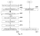
- FIGS. 3 to 5 are flowcharts showing the exemplary operations of the cooperative work system 100.
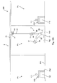
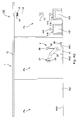
- Figs. 6A to 6E are views showing the exemplary operations of the cooperative work system 100.
- the robot 2 is located at the robot placement position Pb1 of the processing place Pb.
- step S1 a series operations described below, are performed, to move the robot 2 from the processing place Pb (see Fig. 6A ) to the unprocessed workpiece placement place Pa where the unprocessed workpiece 110 is placed (see Fig. 6B ) (step S1).
- the cooperation control section 65 of the robot 2 instructs the crane control section 51 to locate the suspending unit 11 at a predetermined position within the operation region of the robot 2 (e.g., a position that is above the engagement section 28 of the robot 2 located at the robot placement position Pb1) (step S101).
- the crane control section 51 of the crane 1 controls the movement mechanism 18 in response to the instruction provided by the robot 2 to locate the suspending unit 11 at the predetermined position within the operation region of the robot 2, corresponding to the instruction provided by the cooperation control section 65 (step S103). It should be noted that in this control, the transfer position accuracy of the suspending unit 11 may be low.
- control section 60 of the robot 2 determines whether or not the suspending unit 11 is at the predetermined position within the operation region of the robot 2 (step S105).
- the control section 60 of the robot 2 performs this determination based on, for example, whether or not a predetermined time has passed, but this is merely exemplary. Instead of this, the control section 60 of the robot 2 may perform the determination, based on, for example, the position information of the suspending unit 11 which is transmitted from the control section 50 of the crane 1.
- the control section 60 of the robot 2 stands-by until the control section 60 determines that the suspending unit 11 is at the predetermined position within the operation region of the robot 2 (No in step S105). Then, when the control section 60 of the robot 2 determines that the suspending unit 11 is at the predetermined position within the operation region of the robot 2 (Yes in step S105), the robot control section 62 operates the arm 22 to cause the camera 27 to face the above-described predetermined position. Then, the camera 27 takes an image, and the suspending unit position obtaining section 63 of the robot 2 obtains the position of the suspending unit 11 based on this image (step S107).
- the robot control section 62 drives the arm drive section 24 to move the hand 23 to the position at which the suspending unit 11 is located, and drives the hand drive section 25 to cause the hand 23 to perform the holding operation (step S109).
- the suspending unit 11 is held by the hand 23. Therefore, even in a case where the transfer position accuracy of the suspending unit 11 located at the predetermined position, under control of the crane control section 51, is low, the suspending unit 11 can be held by the hand 23.
- the robot control section 62 of the robot 2 drives the arm drive section 24 to guide the suspending unit 11 of the crane 1 which is held by the hand 23, to the engagement section 28 of the robot 2, and causes the engagement section 10 of the suspending unit 11 of the crane 1 and the engagement section 28 of the robot 2 to be engaged with each other (step S111).
- the robot control section 62 of the robot 2 initially drives the arm drive section 24 to move the hand 23 to guide the suspending unit 11 to a position (first guide position) set at a predetermined distance that is above the engagement section 28 of the robot 2, and locate the suspending unit 11 at the first guide position.
- the robot control section 62 of the robot 2 drives the arm drive section 24 to move the hand 23 to guide the suspending unit 11 from the first guide position to a lower position and locate the suspending unit 11 at the lower position.
- This allows the engagement section 10 of the suspending unit 11 and the engagement section 28 of the robot 2 to be engaged with each other.
- the robot 2 treats the robot 2 itself in such a manner that the robot 2 operates the hand 23 and the arm 22 to attach the robot 2 to the crane 1. Therefore, even in a case where the position accuracy of the robot 2 located at the robot placement position Pb1 is low, the robot 2 can be attached to the crane 1 without an operator.
- the cooperation control section 65 of the robot 2 instructs the crane control section 51 to move the suspending unit 11 to move the workpiece 110 attached to the suspending unit 11 to a target position, namely, to the robot placement position Pa1 of the unprocessed workpiece placement place Pa (step S 113).
- the crane control section 51 of the crane 1 controls the movement mechanism 18 in response to the instruction provided by the robot 2 to move (move up, horizontally and down) the suspending unit 11 to transfer (carry) the robot 2 attached to the suspending unit 11 toward the target position (step S 115).
- the suspending unit 11 is automatically disengaged from the engagement section 28 of the robot 2, and thus the robot 2 is detached from the crane 1. It should be noted that in this control, the transfer position accuracy of the robot 2 may be low.
- the control section 60 of the robot 2 determines whether or not the robot 2 has been detached from the crane 1 and has been moved to the unprocessed workpiece placement place Pa (step S2).
- the control section 60 of the robot 2 performs this determination based on, for example, whether or not a predetermined time has passed, but this is merely exemplary. Instead of this, the control section 60 of the robot 2 may perform the determination based on, for example, information indicating that a load of the suspending unit 11 which is transmitted from the control section 50 of the crane 1 becomes zero.
- control section 60 of the robot 2 stands-by until the control section 60 determines that the robot 2 has been moved to the unprocessed workpiece placement place Pa (No in step S2). Then, when the control section 60 determines that the robot 2 has been moved to the unprocessed workpiece placement place Pa (Yes in step S2), the control section 60 of the robot 2 performs a series of operations described below, to move the workpiece 110 from the unprocessed workpiece 110 (see Fig. 6B ) to the processing place Pb (see Fig. 6C ) (step S3).
- the robot control section 62 operates the arm 22 to cause the camera 27 to face the workpiece placement position Pa2. Then, the camera 27 takes an image, and the object engagement section position obtaining section 64 of the robot 2 obtains the position of the engagement section 111 of the workpiece 110 which is a target to be processed, based on this image (step S201).
- the cooperation control section 65 of the robot 2 instructs the crane control section 51 to locate the suspending unit 11 at a predetermined position within the operation region of the robot 2 (e.g., a position that is above the engagement section 111 of the workpiece 110 located at the workpiece placement position Pa2) (step S203).
- the crane control section 51 of the crane 1 controls the movement mechanism 18 in response to the instruction provided by the robot 2 to locate the suspending unit 11 at a predetermined position within the operation region of the robot 2, corresponding to the instruction provided by the cooperation control section 65 (step S205). It should be noted that in this control, the transfer position accuracy of the suspending unit 11 may be low.
- control section 60 of the robot 2 determines whether or not the suspending unit 11 is at the predetermined position within the operation region of the robot 2 (step S207).
- the control section 60 of the robot 2 stands-by until the control section 60 determines that the suspending unit 11 is at the predetermined position within the operation region of the robot 2 (No in step S207). Then, when the control section 60 of the robot 2 determines that the suspending unit 11 is at the predetermined position within the operation region of the robot 2 (Yes in step S207), the robot control section 62 operates the arm 22 to cause the camera 27 to face the above-described predetermined position. Then, the camera 27 takes an image, and the suspending unit position obtaining section 63 of the robot 2 obtains the position of the suspending unit 11 based on this image (step S209).
- the robot control section 62 drives the arm drive section 24 to move the hand 23 to the position at which the suspending unit 11 is located, and drives the hand drive section 25 to cause the hand 23 to perform the holding operation (step S211).
- the suspending unit 11 is held by the hand 23. Therefore, even in a case where the transfer position accuracy of the robot 2 located at the predetermined position and the transfer position accuracy of the suspending unit 11 located at the predetermined position, under control of the crane control section 51, are low, the suspending unit 11 can be held by the hand 23.
- the robot control section 62 of the robot 2 drives the arm drive section 24 to guide the suspending unit 11 of the crane 1 which is held by the hand 23 to the engagement section 111 of the workpiece 110, and causes the engagement section 10 of the suspending unit 11 of the crane 1 and the engagement section 111 of the workpiece 110 to be engaged with each other (step S213).
- the robot control section 62 of the robot 2 initially drives the arm drive section 24 to move the hand 23 to guide the suspending unit 11 to a position (first guide position) set at a predetermined distance that is above the engagement section 111 of the workpiece 110, and locate the suspending unit 11 at the first guide position.
- the robot control section 62 of the robot 2 drives the arm drive section 24 to move the hand 23 to guide the suspending unit 11 from the first guide position to a lower position and locate the suspending unit 11 at the lower position.
- the engagement section 10 of the suspending unit 11 and the engagement section 111 of the workpiece 110 can be engaged with each other.
- the robot 2 treats the workpiece 110 in such a manner that the robot 2 operates the hand 23 and the arm 22 to attach the workpiece 110 to the crane 1.
- the workpiece 110 can be attached to the crane 1 as in a case where an operator works in a conventional method.
- the cooperation control section 65 of the robot 2 instructs the crane control section 51 to move the suspending unit 11 to move the workpiece 110 attached to the suspending unit 11 to a target position, namely, the workpiece processing position Pb2 of the processing place Pb (step S215).
- the crane control section 51 of the crane 1 controls the movement mechanism 18 in response to the instruction provided by the robot 2 to move the suspending unit 11 to transfer (carry) the workpiece 110 attached to the suspending unit 11 toward the target position (step S217).
- the suspending unit 11 is automatically disengaged from the engagement section 111 of the workpiece 110, and thus the workpiece 110 is detached from the crane 1. It should be noted that in this control, the transfer position accuracy of the workpiece 110 may be low.
- the crane 1 moves the workpiece 110 from the workpiece placement position Pa2 to the workpiece processing position Pb2.
- the control section 60 of the robot 2 determines whether or not the workpiece 110 has been detached from the crane 1 and has been moved to the processing place Pb (step S4).
- the control section 60 of the robot 2 performs this determination based on, for example, whether or not a predetermined time has passed, but this is merely exemplary. Instead of this, the control section 60 of the robot 2 may perform the determination, based on, for example, information indicating that the load of the suspending unit 11 which is transmitted from the control section 50 of the crane 1 becomes zero.
- control section 60 of the robot 2 stands-by until the control section 60 determines that the workpiece 110 has been moved to the processing place Pb (No in step S4). Then, when the control section 60 of the robot 2 determines that the workpiece 110 has been moved to the processing place Pb (Yes in step S4), the control section 60 performs a series of operations to move the robot 2 from the unprocessed workpiece placement place Pa (see Fig. 6C ) to the processing place Pb (see Fig. 6D ) (step S5).
- the target position to which the robot 2 is moved in the above-described series of operations in step S1 is the robot placement position Pa1 of the unprocessed workpiece placement place Pa.
- the target position to which the robot 2 is moved in the above-described series of operations in step S5 is the robot placement position Pb1 of the processing place Pb.
- the series of operations in step S5 are the same as those in step S1.
- the crane 1 moves the robot 2 between the robot placement position Pa1 and the robot placement position Pb1.
- the robot 2 can be moved to the processing place of the workpiece 110 for itself, as in a case where the operator works in a conventional method.
- the robot 2 treats the robot 2 itself in such a manner that the robot 2 operates the hand 23 and the arm 22 to attach the robot 2 itself to the crane 1. Therefore, even in a case where the transfer position accuracy of the robot 2 located at the robot placement position Pa1 is low, the robot 2 can be attached to the crane 1, and the operations in the production line can be carried out without the operator.
- the control section 60 of the robot 2 determines whether or not the robot 2 has been detached from the crane 1 and has been moved to the processing place Pb (step S6).
- the control section 60 of the robot 2 performs this determination based on, for example, whether or not a predetermined time has passed, but this is merely exemplary. Instead of this, the control section 60 of the robot 2 may perform the determination, based on, for example, information indicating that the load of the suspending unit 11 which is transmitted from the control section 50 of the crane 1 becomes zero.
- control section 60 of the robot 2 stands-by until the control section 60 determines that the robot 2 has been moved to the processing place Pb (No in step S6). Then, when the control section 60 determines that the robot 2 has been moved to the processing place Pb (Yes in step S6), the robot 2 processes the workpiece 110 (step S7).
- the robot 2 drives the hand drive section 25 to cause the hand 23 to perform the mounting operation for mounting a tool which is not shown, and then process the workpiece 110 by use of the tool.
- the robot 2 drives the hand drive section 25 to cause the hand 23 to perform the detaching operation for detaching the tool mounted to the hand 23.
- control section 60 of the robot 2 performs a series of operations, to move the workpiece 110 from the processing place Pb (see Fig. 6D ) to the processed workpiece placement place Pc (see Fig. 6E ) (step S8).
- the target position to which the workpiece 110 is moved in the above-described series of operations in step S3 is the workpiece processing position Pb2 of the processing place Pb.
- the target position to which the workpiece 110 is moved in the above-described series of operations in step S8 is the processed workpiece placement place Pc.
- the series of operations in step S8 are the same as those in step S3.
- the workpiece 110 can be attached to the crane 1.
- the cooperative work system 100 can transfer the workpiece 110 located at the unprocessed workpiece placement place Pa to the processing place Pb, process the workpiece 110 in the processing place Pb, and transfer the processed workpiece 110 to the processed workpiece placement place Pc.
- the series of operations in the production line can be performed without an operator.
- the robot 2 is configured to engage the engagement section 10 of the suspending unit 11 of the crane 1 and the engagement section 111 of the workpiece 110 with each other, and engage the engagement section 28 of the robot 2 itself and the engagement section 10 of the suspending unit 11 of the crane 1 with each other. Therefore, even in a case where the transfer position accuracy of the suspending unit 11 of the crane 1 is low or a case where the transfer position accuracy of the workpiece 110 or the robot 2 which is transferred (carried) by the crane 1 is low, the workpiece 110 or the robot 2 can be attached to the crane 1, and the above-described series of operations can be carried out. In addition, the configuration for attaching the workpiece 110 or the robot 2 to the crane 1 can be simplified. As a result, the cooperative work system 100 can be constructed in an inexpensive manner.
- the robot 2 is moved between the unprocessed workpiece placement place Pa and the processing place Pb and engages the engagement section 10 of the suspending unit 11 of the crane 1 and the engagement section 111 of the workpiece 110 with each other, the number of robots included in the cooperative work system 100 can be reduced. As a result, the cooperative work system 100 can be constructed in an inexpensive manner.
- the robot 2 and the workpiece 110 are transferred (carried) by the crane 1. Therefore, unlike in a case where the robot 2 moves for itself without being transferred by other means between the unprocessed workpiece placement place Pa and the processing place Pb, or a case where the workpiece 110 is conveyed by a conveyor, it is not necessary to provide a path through which the robot 2 moves or a path through which the workpiece 110 is conveyed, a space in which the system is installed is not increased, and a floor area required to transfer the workpiece 110 is not increased.
- the robot 2 and the crane 1 can work (operate) cooperatively, to move the workpiece 110 among the unprocessed workpiece placement place Pa, the processing place Pb, and the processed workpiece placement place Pc, which are located to be distant from each other, and the robot 2 can process the workpiece 110 in the processing space Pb.
- the workpiece 110 can be transferred (carried) and processed by use of the robot 2, as in a case where the operator works in the conventional method.
- the present invention can solve a problem that the number of operators who work in the production line is reduced, or the operations in the production line can be carried out without the operator, by use of a new method in which the robot 2 attaches the workpiece 110 to the crane 1 to transfer the workpiece 110 as in a case where the operator works in the conventional method, the robot 2 is moved among the unprocessed workpiece placement place Pa, the processing place Pb, and the processed workpiece placement place Pc, which are located to be distant from each other, as in a case where the operator moves among the unprocessed workpiece placement place Pa, the processing place Pb, and the processed workpiece placement place Pc, in the conventional method, and thus the robot performs the whole of the operator's work in the production line, without providing special equipment or device for automation, such as an automatic conveyor transfer device.
- the robot 2 is configured to instruct the crane 1 to operate (perform the operation), the operations in the production line in which the workpiece is transferred and processed can be carried out without the operator.
- the workpiece 110 can be transferred and processed by use of the robot 2, and the floor area required to transfer the workpiece 110 is not increased.
- the cooperative work system 100 includes the crane 1 which is a single crane.
- a cooperative work system may include a plurality of cranes.
- transferring the workpiece 110 from the unprocessed workpiece placement place Pa to the processing place Pb in step S3 and transferring the robot 2 from the unprocessed workpiece placement place Pa to the processing place Pb in step S5 may be performed concurrently, by use of the plurality of cranes.
- a certain crane transfers the workpiece 110 and puts it down onto the target position in the processing place Pb or the target position in the processed workpiece placement place Pc
- another crane may transfer the robot 2 to the processing place Pb or the processed workpiece placement place Pc.
- the robot control section 62 of the robot 2 operates the arm 22 and the hand 23 to hold the workpiece 110 to be put down onto the processing place Pb or the processed workpiece placement place Pc so that the posture and positioning of the workpiece 110 to be placed at the target position can be determined.
- the suspending unit 11 when the workpiece 110 or the robot 2 is placed at the target position, the suspending unit 11 is automatically disengaged from the engagement section 111 of the workpiece 110 or the engagement section 28 of the robot 2, and thus the workpiece 110 or the robot 2 is automatically detached from the crane 1.
- the robot 2 may detach the workpiece 110 or the robot 2 itself which is suspended by the crane 1 in such a manner that the robot 2 operates the hand 23 and the arm 22 to detach the suspending unit 11 from the engagement section 111 of the workpiece 110 or the engagement section 28 of the robot 2
- Fig. 7 is a view showing the exemplary configuration of a cooperative work system 400 according to Embodiment 4.
- Fig. 8 is a block diagram schematically showing the exemplary configuration of a control system of the cooperative work system 400.
- the cooperative work system 400 of Embodiment 4 further includes a swing preventing member 401 provided on each of the unprocessed workpiece placement place Pa and the processing place Pb, in addition to the above-described constituents of Embodiment 1.
- the swing preventing member 401 is a columnar member provided on each of the robot placement position Pa1 and the processing place Pb, or a location which is adjacent to the robot placement position Pa1 or the processing place Pb in such a manner that the swing preventing member 401 extends vertically upward.
- the swing preventing member 401 is an elastic body, and is made of, for example, rubber.
- the swing preventing member 401 includes a holding section 402 in a top portion thereof, which is to be held by the hand 23 of the robot 2.
- the cooperative work system 400 according to Embodiment 4 is configured in such a manner that the control section 60 of the robot 2 includes a holding section detecting/position obtaining section 403.
- the holding section detecting/position obtaining section 403 processes an image taken by the camera 27, to detect the holding section 402 and obtain the position of the holding section 402.
- the robot 2 suspended by the crane 1 swings, just before the robot 2 is positioned.
- the robot 2 is caused to hold the swing preventing member 401 so that the robot 2 ceases to swing.
- it is necessary to obtain the position of the swing preventing member 401 during the positioning operation of the robot 2.
- the robot control section 62 operates the arm 22 to cause the camera 27 to face the swing preventing member 401 which is a target position to which the robot 2 should be moved. Then, the camera 27 successively takes the images of the target position, and based on the taken images, the robot control section 62 determines whether or not the holding section detecting/position obtaining section 403 has detected the holding section 402.
- the robot control section 62 determines that the holding section detecting/position obtaining section 403 has detected the holding section 402
- the holding section detecting/position obtaining section 403 obtains real time position of the holding section 402.
- the robot control section 62 determines whether or not the holding section 402 is located within the operation region of the robot 2.
- the robot control section 62 drives the arm drive section 24 to move the hand 23 to the position at which the holding section 402 is located, and drives the hand drive section 25 to cause the hand 23 to perform the holding operation.
- the hand 23 holds the holding section 402.
- the swing preventing member 401 is deflected to absorb the swing of the robot 2 suspended by the crane 1. In this way, the swing of the robot 2 suspended by the crane 1 can quickly converge, and the robot 2 can be quickly located at the robot placement position Pa1 or the robot placement position Pb1 with a high accuracy.
- Fig. 9 is a view showing the exemplary configuration of a cooperative work system 500 according to Embodiment 5.
- Fig. 10 is a block diagram schematically showing the exemplary configuration of a control system of the cooperative work system 500.
- the cooperative work system 500 according to Embodiment 5 includes markers 510 attached to spots which are in the vicinity of the robot placement position Pa1 and the robot placement position Pb1, in addition to the constituents of the above-described Embodiment 1.
- the markers 510 refer to, for example, patterns which are drawn on the floor surface and can be distinguished from other parts.
- the control section 60 of the robot 2 in the cooperative work system 500 according to Embodiment 5 is configured to include a marker detecting section 501.
- the marker detecting section 501 processes the images taken by the camera 27 to detect the markers 510 at the robot placement position Pa1 or the robot placement position Pb1.
- the cooperation control section 65 of the robot 2 instructs the crane control section 51 of the crane 1 to locate the robot 2 at the robot placement position Pa1 or the robot placement position Pb1, based on a relative positional relationship between the markers 510 detected by the marker detecting section 501, and the robot 2.
- the robot 2 can be located at the robot placement position Pa1 or the robot placement position Pb1, with a high accuracy.
- Fig. 11 is a block diagram schematically showing the exemplary configuration of a control system of a cooperative work system 600 according to Embodiment 6.
- the cooperation control section 65 which instructs the crane control section 51 to operate the crane 1 is included in the control section 60 of the control unit 26 of the robot 2.
- the cooperative work system 600 is configured in such a manner that a system control unit 626 which is separate from the crane 1 and the robot 2 instructs the crane 1 and the robot 2 to operate (perform operations).
- the system control unit 626 includes a system control section 660 including a cooperation control section 665 and a communication control section 666, and a communication section 670.
- the cooperation control section 665 instructs the robot control section 62 to operate the robot, via the communication control section 666, the communication section 670, the robot communication section 30, and the communication control section 66.
- the cooperation control section 665 instructs the crane control section 51 to operate the crane, via the communication control section 666, the communication section 670, the crane communication section 17, and the communication control section 52.
- the communication control section 666 controls the communication section 670.
- the communication section 670 performs, for example, a wireless communication with the robot communication section 30, the crane communication section 17, and others, under control of the communication control section 666.
- the cooperative work system 600 of the present embodiment is configured in such a manner that the system control section 660 instructs the crane 1 and the robot 2.
- Fig. 12 is a block diagram schematically showing the exemplary configuration of a control system of a cooperative work system 700 according to Embodiment 7.
- the cooperation control section 65 which instructs the crane control section 51 to operate the crane 1 is included in the control section 60 of the control unit 26 of the robot 2.
- the cooperative work system 700 is configured in such a manner that the control section 50 of the crane 1 instructs the robot 2 to operate (perform an operation).
- the control section 50 of the crane 1 further includes a cooperation control section 753.
- the cooperation control section 753 instructs the robot control section 62 to operate the robot, via the communication control section 52, the crane communication section 17, the robot communication section 30, and the communication control section 66.
- the cooperative work system 700 is configured in such a manner that the crane 1 instructs the robot 2 to operate (perform the operation).
- the control section 60 of the robot 2 may be configured to instruct the crane control section 51 of the crane 1 to attach the robot 2 to the crane 1 and transfer (carry) the robot 2 to a spot that is near a battery charger (not shown) which charges the battery 29, when the control section 60 of the robot 2 determines that the SOC (state of charge) of the battery 29 becomes less than a predetermined value. Then, when the control section 60 of the robot 2 determines that the robot 2 is located near the battery charger, the robot control section 62 of the robot 2 operates, for example, the arm 22 and the hand 23, to connect the robot 2 and the battery charger to each other so that the electric power can be supplied to the battery 29. This makes it possible to prevent a situation in which the battery 29 of the robot 2 runs down.
- the robot 2 includes the camera 27, and the suspending unit position obtaining section 63 of the robot 2 processes the image taken by the camera 27 to obtain the position of the suspending unit 11 of the crane 1, and the object engagement section position obtaining section 64 of the robot 2 processes the image taken by the camera 27 to obtain the position of the engagement section 111 of the workpiece 110.
- the robot 2 does not include the camera 27.
- the suspending unit position obtaining section 63 of the robot 2 obtains the position of the suspending unit 11 of the crane 1, based on the position information of the suspending unit 11 which is transmitted from the crane 1 to the robot 2.
- the object engagement section position obtaining section 64 obtains the position of the engagement section 111 of the workpiece 110 based on the placement position of the workpiece 110 which is transmitted from the crane 1 to the robot 2.
- the robot 2 is configured to hold the holding section 402, and thus the swing of the robot 2 converges.
- the robot 2 including an acceleration sensor may move the arm 22 to cancel the swing so that the swing of the robot 2 converges.
- an electric magnet may be provided on the floor surface, and another electric magnet may be provided on the robot base section 21 of the robot 2 so that the swing of the robot 2 converges by attractive forces generated by these electric magnets, when the robot 2 is placed on the floor surface.
- step S105, step S2, step S207, step S4, and step S6 of the above-described Embodiment 1 the control section 60 of the robot 2 may instruct the crane 1 to locate the corresponding target object again.
- the invention of the present application is applicable to a production line.
Landscapes
- Engineering & Computer Science (AREA)
- Mechanical Engineering (AREA)
- Robotics (AREA)
- Multimedia (AREA)
- Manipulator (AREA)
- Control And Safety Of Cranes (AREA)
Abstract
Description
- The present invention relates to a robot and crane cooperative work system, in which a robot and a crane work (operate) cooperatively.
- Conventionally, there is known a system in which a workpiece is transferred (carried) by use of a robot to reduce the number of operators who work in factories (see e.g., Patent Literature 1).
- This system which transfers the workpiece includes the robot including a holding section, and a balancer including a holding section for holding the workpiece, and a seat. The holding section of the robot holds the seat of the balancer on which the workpiece is held by the holding section of the balancer, and the robot moves the holding section thereof to a transfer position according to a transfer track. In this way, the workpiece can be located at the transfer position.
- Patent Literature 1: Japanese Laid-Open Patent Application Publication No.
Hei. 9-1492 - However, the system which transfers the workpiece, disclosed in
Patent Literature 1, has a problem that the workpiece cannot be transferred to a spot which is outside the operation region of the robot. - Since the workpiece is transferred to the spot which is outside the operation region of the robot by a production line, an automatic conveyor transfer device may convey the workpiece. However, in this case, a great floor area is required to install a conveyor, which increases the floor area occupied by the system.
- In addition, the robot does not instruct a crane (e.g., overhead crane) to transfer (carry) the workpiece. Also, the crane does not transfer the robot which works.
- The present invention has been made to solve the above-described problem, and an object of the present invention is to provide a robot and crane cooperative work system which can, by use of the robot, transfer and process a workpiece as in a case where an operator works in a conventional method, and prevent an increase in a floor area required to transfer the workpiece
- Another object of the present invention is to reduce the number of operators who work in a production line and perform operations in the production line without an operator, without providing special equipment or device for automation, such as an automatic conveyor transfer device
- To achieve the above-described object, according to an aspect of the present invention, a robot and crane cooperative work system, comprises: a robot including a hand and an arm which are capable of treating a workpiece or to which a tool is mountable; and a crane which moves an object which is the workpiece or the robot, while suspending the object by the crane, wherein the robot treats the object in such a manner that the robot operates the hand and the arm to attach the object to the crane or detach the object from the crane, the crane moves the object, and the robot processes the workpiece.
- In accordance with this configuration, the robot can treat the object in such a manner that the robot operates the hand and the arm to attach the object to the crane or detach the object from the crane, the crane can move the workpiece to a predetermined place which is outside the operation region of the robot, and the robot can process the workpiece. Therefore, by use of the robot, the workpiece can be transferred and processed as in a case where an operator works in a conventional method. That is, the robot performs the whole of the operator's work in the production line. Therefore, without providing special equipment or device for automation, such as an automatic conveyor transfer device, the number of operators working in the production line can be reduced, or the operations in the production line can be carried out without an operator, with a simple configuration.
- Since the robot and the crane are transferred by the crane, it becomes possible to prevent an increase in a floor area required to transfer the workpiece.
- The robot and crane cooperative work system may further comprise a system control section, wherein the crane and the robot may be configured to allow the system control section to instruct the crane and the robot to perform operations, and the system control section may instruct the crane and the robot to perform the operations.
- In accordance with this configuration, the robot works as in a case where the operator works in the conventional method. Therefore, the operations in the production line can be performed without the operator.
- The crane and the robot may be configured to allow the robot to instruct the crane to perform an operation, and the robot may instruct the crane to perform the operation.
- In accordance with this configuration, the robot works as in a case where the operator works in the conventional method. Therefore, the operations in the production line can be performed without the operator.
- The crane and the robot may be configured to allow the crane to instruct the robot to perform an operation, and the crane may instruct the robot to perform the operation.
- In accordance with this configuration, the robot works as in a case where the operator works in the conventional method. Therefore, the operations in the production line can be performed without the operator.
- The robot may be configured to treat the object in such a manner that the robot operates the hand and the arm to attach the object to the crane.
- In accordance with this configuration, even in a case where the position accuracy of the workpiece or the robot which is located at a predetermined position is low, the robot can attach the workpiece or the robot itself to the crane. In addition, a configuration for attaching the workpiece or the robot to the crane can be simplified.
- The robot may be configured to treat the object in such a manner that the robot operates the hand and the arm to detach the object suspended by the crane from the crane.
- In accordance with this configuration, even in a case where the transfer position accuracy of the workpiece or the robot which is transferred by the crane is low, the robot can detach the workpiece or the robot itself from the crane.
- The object may be the robot.
- In accordance with this configuration, the robot attaches the robot itself to the crane or detach the robot itself from the crane. Therefore, the robot can move to the processing place of the workpiece for itself.
- The object may be the workpiece.
- In accordance with this configuration, since the robot attaches the workpiece to the crane, the workpiece can be attached to the crane without the operator, even when the position accuracy of the workpiece located at the predetermined position is low. Or, since the robot detaches the workpiece from the crane, the workpiece can be detached from the crane without the operator, even when the accuracy of the position to which the workpiece is transferred by the crane is low.
- The object may include an engagement section, and the crane includes a suspending unit which is engageable with the engagement section of the object, and the robot may cause the hand to hold the suspending unit, and attach the held suspending unit to the engagement section of the object or detach the held object from the engagement section of the object.
- In accordance with this configuration, the robot can suitably attach the workpiece or the robot to the crane.
- The crane may include: a movement mechanism which moves up and down the suspending unit and moves the suspending unit horizontally; and a crane control section which controls an operation of the movement mechanism, the robot may include: a robot base section placed on a placement surface; the arm having a base end portion coupled to the robot base section; the hand mounted to a tip end portion of the arm; a robot control section which controls an operation of the arm and an operation of the hand; an object engagement section position obtaining section which obtains a position of the engagement section of the object; and a suspending unit position obtaining section which obtains a position of the suspending unit of the crane, the robot control section may cause the hand to hold the suspending unit based on the position of the suspending unit which is obtained by the suspending unit position obtaining section, and move the hand to guide the suspending unit to a first guide position set based on the position of the engagement section which is obtained by the object engagement section position obtaining section.
- In accordance with this configuration, the robot can more suitably attach the workpiece or the robot to the crane.
- The robot may further include a camera mounted to the hand or the arm, and the object engagement section position obtaining section may be configured to process an image taken by the camera to obtain the position of the engagement section, and the suspending unit position obtaining section is configured to process the image taken by the camera to obtain the position of the suspending unit.
- In accordance with this configuration, the robot can obtain, for itself, the position of the engagement section of the object and the position of the suspending unit of the crane.
- The present invention can obtain an advantage that it is possible to provide a robot and crane cooperative work system which can transfer and process a workpiece by use of a robot, as in a case where an operator works in a conventional method, and prevent an increase in a floor area required to transfer the workpiece.
-
-
Fig. 1 is a view showing the exemplary configuration of a robot and crane cooperative work system according to Embodiment 1 of the present invention. -
Fig. 2 is a block diagram schematically showing the exemplary configuration of a control system of the robot and crane cooperative work system ofFig. 1 . -
Fig. 3 is a flowchart showing the exemplary operation of the robot and crane cooperative work system ofFig. 1 . -
Fig. 4 is a flowchart showing the exemplary operation of the robot and crane cooperative work system, in step S1 ofFig. 3 . -
Fig. 5 is a flowchart showing the exemplary operation of the robot and crane cooperative work system, in step S3 ofFig. 3 . -
Fig. 6A is a view showing the exemplary operation of the robot and crane cooperative work system ofFig. 1 . -
Fig. 6B is a view showing the exemplary operation of the robot and crane cooperative work system ofFig. 1 . -
Fig. 6C is a view showing the exemplary operation of the robot and crane cooperative work system ofFig. 1 . -
Fig. 6D is a view showing the exemplary operation of the robot and crane cooperative work system ofFig. 1 . -
Fig. 6E is a view showing the exemplary operation of the robot and crane cooperative work system ofFig. 1 . -
Fig. 7 is a view showing the exemplary configuration of a robot and crane cooperative work system according to Embodiment 4 of the present invention. -
Fig. 8 is a block diagram schematically showing the exemplary configuration of a control system of the robot and crane cooperative work system ofFig. 6 . -
Fig. 9 is a view showing the exemplary configuration of a robot and crane cooperative work system according to Embodiment 5 of the present invention. -
Fig. 10 is a block diagram schematically showing the exemplary configuration of a control system of the robot and crane cooperative work system ofFig. 8 . -
Fig. 11 is a view showing the exemplary configuration of a robot and crane cooperative work system according to Embodiment 6 of the present invention. -
Fig. 12 is a view showing the exemplary configuration of a robot and crane cooperative work system according toEmbodiment 7 of the present invention. - Hereinafter, the embodiments of the present invention will be described with reference to the drawings. It should be noted that the present invention is not limited by the embodiments. Throughout the drawings, the same or corresponding components are designated by the same reference symbols and will not be described repeatedly.
-
Fig. 1 is a view showing the exemplary configuration of a robot and cranecooperative work system 100 according toEmbodiment 1 of the present invention, in which a robot and a crane work (operate) cooperatively - As shown in
Fig. 1 , thecooperative work system 100 is installed on, for example, a work place where aworkpiece 110 is to be processed, such as a production line, and includes acrane 1 and arobot 2. It should be noted that the place where thecooperative work system 100 is installed is not limited to the production line. - In this production line, an unprocessed workpiece placement place Pa, a processing place Pb, and a processed workpiece placement place Pc which are set (disposed) in places which are distant from each other.
- The unprocessed workpiece placement place Pa is a place where the
workpiece 110 which is unprocessed (is not processed yet) is placed. In the unprocessed workpiece placement place Pa, a robot placement position Pa1 which is a location at which the robot is placed, and a workpiece placement position Pa2 which is a location at which the workpiece is placed are set. Theworkpiece 110 located at the workpiece placement position Pa2 is set to be located within the operation region (which will be described later) of therobot 2 located at the robot placement position Pa1. - The processing place Pb is a place where the
robot 2 processes theworkpiece 110. In the processing place Pb, a robot placement position Pb1 which is a location at which the robot is placed, and a workpiece processing position Pb2 at which the workpiece is processed are set. Theworkpiece 110 located at the workpiece processing position Pb2 is set to be located within the operation region (which will be described later) of therobot 2 placed at the robot placement position Pb1. - The processed workpiece placement place Pc is a place where the
workpiece 110 having been processed by therobot 2 is placed. - The
workpiece 110 includes aworkpiece body 112 and anengagement section 111 which is engageable with anengagement section 10 of a suspendingunit 11 of thecrane 1 which will be described later. Theengagement section 111 is provided immediately above, for example, the center of gravity of theworkpiece 110, and bears a load of theworkpiece 110 suspended by thecrane 1. - The
crane 1 is, for example, an overhead crane provided in the vicinity of a ceiling of a building in which the production line is installed. However, the configuration of thecrane 1 is not limited to the overhead crane and may be arbitrary. - The
crane 1 includes the suspendingunit 11, awire rope 12, awinch 13, atrolley 14, a travelingrail 15, a control unit 16 (seeFig. 2 ), and a crane communication section 17 (seeFig. 2 ). - The suspending
unit 11 includes theengagement section 10 which is engageable with theengagement section 111 of theworkpiece 110 and anengagement section 28 of therobot 2 which will be described later. The suspendingunit 11 can be held by ahand 23 of therobot 23 which will be described later. - In the present embodiment, the suspending
unit 11 includes an automatic hook mechanism, which allows the suspendingunit 11 to be automatically detached from theengagement section 111 of theworkpiece 110 and theengagement section 28 of therobot 2. This automatic hook mechanism is configured to cause the suspendingunit 11 to be disengaged from theengagement section 111 of theworkpiece 110 and theengagement section 28 of therobot 2, when a load applied to thewire rope 12 becomes zero, for example. A well-known automatic hook mechanism can be used as the automatic hook mechanism, and therefore, further description of the automatic hook mechanism will not be given. - The
engagement section 10 is, for example, a lever formed inside a groove extending upward from the lower end of the suspendingunit 11. Theengagement section 10 is moved down from a position that is above theengagement section 111 of theworkpiece 110 or theengagement section 28 of therobot 2 which will be described later, and theengagement section 111 of theworkpiece 110 or theengagement section 28 of therobot 2 which will be described later, is inserted into the groove of the suspendingunit 11. Thereby, theengagement section 10 is moved into the groove of the suspendingunit 11, and theengagement section 111 or theengagement section 28 is retained within the groove of the suspendingunit 11. In this way, theengagement section 10 of thecrane 1 and theengagement section 111 of theworkpiece 110 can be engaged with each other. Or, theengagement section 10 of thecrane 1 and theengagement section 28 of therobot 2 can be engaged with each other. - The lower end of the
wire rope 12 is attached to the suspendingunit 11. Thewire rope 12 extends upward from the suspendingunit 11. The upper end portion of thewire rope 12 is reeled-off by thewinch 13. - The
winch 13 reels-off and reels-out thewire rope 12 around a drum (not shown) to move up and down the suspendingunit 11. Thewinch 13 includes a drive section (not shown) which rotates the drum. - The
winch 13 is mounted to thetrolley 14. Thetrolley 14 is a car which moves thewinch 13. Thetrolley 14 is driven to travel by a drive section provided at thetrolley 14. Thetrolley 14 horizontally moves the suspendingunit 11. - As described above, the drive section of the
winch 13 and the drive section of thetrolley 14 are provided at thewinch 13 and thetrolley 14, respectively. Alternatively, for example, the drive section of thewinch 13 and the drive section of thetrolley 14 may be externally provided with respect to thewinch 13 and thetrolley 14. Thewinch 13 and thetrolley 14 constitute a movement mechanism 18 (seeFig. 2 ). - The traveling
rail 15 is a rail which supports and guides thetrolley 14. The travelingrail 15 extends through a region that is above the robot placement position Pa1 and the workpiece placement position Pa2 of the unprocessed workpiece placement place Pa, the robot placement position Pb1 and the workpiece processing position Pb2 of the processing place Pb, and the processed workpiece placement place Pc. -
Fig. 2 is a block diagram schematically showing the exemplary configuration of a control system of thecooperative work system 100. - As shown in
Fig. 2 , thecontrol unit 16 of thecrane 1 includes acontrol section 50 and is configured to include, for example, a microcontroller, a CPU, a MPU, a logic circuit, a PLC (programmable logic controller), etc.. The control unit may be configured as a single control unit which performs a control in a centralized manner, or as a plurality of control units which perform a control in a distributed manner. - The
control section 50 includes acrane control section 51 and acommunication control section 52. Thecrane control section 51 and thecommunication control section 52 are functional blocks realized by control programs executed by a processor. - The
crane control section 51 controls themovement mechanism 18, namely, the drive section of thewinch 13 and the drive section of thetrolley 14, to move the suspendingunit 11. Thecommunication control section 52 controls thecrane communication section 17. - The
crane communication section 17 performs, for example, a wireless communication with therobot communication section 30, under control of thecommunication control section 52. - As shown in
Figs. 1 and2 , therobot 2 is, for example, a multi-joint type industrial robot. Therobot 2 includes arobot base section 21, anarm 22, thehand 23, an arm drive section 24 (seeFig. 2 ), a hand drive section 25 (seeFig. 2 ), a control unit 26 (seeFig. 2 ), acamera 27, theengagement section 28, and a robot communication section 30 (seeFig. 2 ). - The
robot base section 21 is a board placed on a placement surface such as a floor surface of the production line, in a state in which therobot base section 21 is not fixed to the placement surface. Therobot base section 21 supports thearm 22 and thehand 23. - The
arm 22 includes, for example, a plurality of joints, and the base end portion of thearm 22 is coupled to therobot base section 21 in such a manner that thearm 22 is rotatable. - The
hand 23 is configured to perform a holding operation for holding an object and a releasing operation for releasing the object from thehand 23. Thehand 23 is attached to the tip end portion of thehand 23. In addition, thehand 23 is configured to perform a mounting operation for mounting a tool used in a work performed in the processing place Pb and a detaching operation for detaching the mounted tool. - The
arm drive section 24 drives thearm 22 to locate thehand 23 at a predetermined position within the operation region of therobot 2. - The
hand drive section 25 drives thehand 23 to cause thehand 23 to perform the holding operation, the releasing operation, the mounting operation, and the detaching operation. - The
camera 27 is, for example, a stereo video camera which is able to take a three-dimensional motion image. By processing the image taken by thecamera 27, a distance between a target object and a position of the target object being in this image, on a picture plane (vision), can be obtained. Thecamera 27 is attached to thehand 23. Therefore, by moving thearm 22, thecamera 27 can take an image in a desired direction. The location at which thecamera 27 is attached is not limited to thehand 23. - In the present embodiment, the
robot 2 is a power supply built-in robot, which contains abattery 29 for supplying electric power used to drive thearm 22 and thehand 23. This makes it possible to drive therobot 2 without connecting therobot 2 to an external power supply via a power supply cable. Alternatively, therobot 2 may be supplied with electric power in a wireless manner. - The
engagement section 28 is configured to be engageable with, for example, theengagement section 10 of the suspendingunit 11 of thecrane 1. Theengagement section 28 is located immediately above, for example, the center of gravity of therobot 2, and bears the load of therobot 2 suspended by thecrane 1. - As shown in
Fig. 2 , thecontrol unit 26 of the robot includes acontrol section 60 and amemory section 61 and is configured to include, for example, a microcontroller, a CPU, a MPU, a logic circuit, a PLC, etc.. This control unit may be configured as a single control unit which performs a control in a centralized manner, or as a plurality of control units which perform a control in a distributed manner. - The
memory section 61 includes memories such as a ROM and a RAM. Information used to identify the position of theengagement section 28 of therobot 2 is stored in thememory section 61. - The
control section 60 includes arobot control section 62, a suspending unitposition obtaining section 63, an object engagement sectionposition obtaining section 64, acooperation control section 65, and acommunication control section 66. - The
robot control section 62, the suspending unitposition obtaining section 63, the object engagement sectionposition obtaining section 64, thecooperation control section 65, and thecommunication control section 66, are functional blocks realized by execution of specified control programs stored in thememory section 61, by a processor. - The
robot control section 62 controls thearm drive section 24 to operate thearm 22, and controls thehand drive section 25 to operate thehand 23. In addition, therobot control section 62 controls the operation of the tool mounted to thehand 23. - The suspending unit
position obtaining section 63 processes the image taken by thecamera 27 to obtain the position of the suspendingunit 11 of thecrane 1. Thus, therobot 2 is able to obtain the position of the suspendingunit 11 of thecrane 1 for itself. - The object engagement section
position obtaining section 64 obtains the position of theengagement section 28 of therobot 2, and the position of theengagement section 111 of theworkpiece 110. The position of theengagement section 28 of therobot 2 is obtained in such a manner that the object engagement sectionposition obtaining section 64 reads-in the position information of theengagement section 28 of therobot 2 which is stored in thememory section 61. The position of theengagement section 111 of theworkpiece 110 is obtained in such a manner that the object engagement sectionposition obtaining section 64 processes the image taken by thecamera 27. In this way, therobot 2 can obtain, for itself, the position of theengagement section 28 of therobot 2 or the position of theengagement section 111 of theworkpiece 110. - The
cooperation control section 65 instructs thecrane control section 51 to operate the crane, via thecommunication control section 66, therobot communication section 30, thecrane communication section 17, and thecommunication control section 52. - The
communication control section 66 controls therobot communication section 30. - The
robot communication section 30 performs, for example, a wireless communication with thecrane communication section 17, under control of thecommunication control section 66. - It should be noted that a communication means between the
crane 1 and therobot 2 is not limited to a wireless communication means. - Next, the exemplary operation of the
cooperative work system 100 will be described. This operation is carried out by thecontrol unit 26 of therobot 2 and thecontrol unit 16 of thecrane 1. -
Figs. 3 to 5 are flowcharts showing the exemplary operations of thecooperative work system 100.Figs. 6A to 6E are views showing the exemplary operations of thecooperative work system 100. - As shown in
Fig. 6A , at the initial state of the present exemplary operation, therobot 2 is located at the robot placement position Pb1 of the processing place Pb. - As shown in
Fig. 3 , firstly, a series operations described below, are performed, to move therobot 2 from the processing place Pb (seeFig. 6A ) to the unprocessed workpiece placement place Pa where theunprocessed workpiece 110 is placed (seeFig. 6B ) (step S1). - Specifically, as shown in
Fig. 4 , initially, thecooperation control section 65 of therobot 2 instructs thecrane control section 51 to locate the suspendingunit 11 at a predetermined position within the operation region of the robot 2 (e.g., a position that is above theengagement section 28 of therobot 2 located at the robot placement position Pb1) (step S101). - Then, the
crane control section 51 of thecrane 1 controls themovement mechanism 18 in response to the instruction provided by therobot 2 to locate the suspendingunit 11 at the predetermined position within the operation region of therobot 2, corresponding to the instruction provided by the cooperation control section 65 (step S103). It should be noted that in this control, the transfer position accuracy of the suspendingunit 11 may be low. - Then, the
control section 60 of therobot 2 determines whether or not the suspendingunit 11 is at the predetermined position within the operation region of the robot 2 (step S105). Thecontrol section 60 of therobot 2 performs this determination based on, for example, whether or not a predetermined time has passed, but this is merely exemplary. Instead of this, thecontrol section 60 of therobot 2 may perform the determination, based on, for example, the position information of the suspendingunit 11 which is transmitted from thecontrol section 50 of thecrane 1. - Then, the
control section 60 of therobot 2 stands-by until thecontrol section 60 determines that the suspendingunit 11 is at the predetermined position within the operation region of the robot 2 (No in step S105). Then, when thecontrol section 60 of therobot 2 determines that the suspendingunit 11 is at the predetermined position within the operation region of the robot 2 (Yes in step S105), therobot control section 62 operates thearm 22 to cause thecamera 27 to face the above-described predetermined position. Then, thecamera 27 takes an image, and the suspending unitposition obtaining section 63 of therobot 2 obtains the position of the suspendingunit 11 based on this image (step S107). Then, therobot control section 62 drives thearm drive section 24 to move thehand 23 to the position at which the suspendingunit 11 is located, and drives thehand drive section 25 to cause thehand 23 to perform the holding operation (step S109). By this holding operation, the suspendingunit 11 is held by thehand 23. Therefore, even in a case where the transfer position accuracy of the suspendingunit 11 located at the predetermined position, under control of thecrane control section 51, is low, the suspendingunit 11 can be held by thehand 23. - Then, the
robot control section 62 of therobot 2 drives thearm drive section 24 to guide the suspendingunit 11 of thecrane 1 which is held by thehand 23, to theengagement section 28 of therobot 2, and causes theengagement section 10 of the suspendingunit 11 of thecrane 1 and theengagement section 28 of therobot 2 to be engaged with each other (step S111). At this time, therobot control section 62 of therobot 2 initially drives thearm drive section 24 to move thehand 23 to guide the suspendingunit 11 to a position (first guide position) set at a predetermined distance that is above theengagement section 28 of therobot 2, and locate the suspendingunit 11 at the first guide position. Then, therobot control section 62 of therobot 2 drives thearm drive section 24 to move thehand 23 to guide the suspendingunit 11 from the first guide position to a lower position and locate the suspendingunit 11 at the lower position. This allows theengagement section 10 of the suspendingunit 11 and theengagement section 28 of therobot 2 to be engaged with each other. In the above-described manner, in the configuration of thecooperative work system 100, therobot 2 treats therobot 2 itself in such a manner that therobot 2 operates thehand 23 and thearm 22 to attach therobot 2 to thecrane 1. Therefore, even in a case where the position accuracy of therobot 2 located at the robot placement position Pb1 is low, therobot 2 can be attached to thecrane 1 without an operator. - Then, the
cooperation control section 65 of therobot 2 instructs thecrane control section 51 to move the suspendingunit 11 to move theworkpiece 110 attached to the suspendingunit 11 to a target position, namely, to the robot placement position Pa1 of the unprocessed workpiece placement place Pa (step S 113). - Then, the
crane control section 51 of thecrane 1 controls themovement mechanism 18 in response to the instruction provided by therobot 2 to move (move up, horizontally and down) the suspendingunit 11 to transfer (carry) therobot 2 attached to the suspendingunit 11 toward the target position (step S 115). When therobot 2 is placed at the target position (robot placement position Pa1), the suspendingunit 11 is automatically disengaged from theengagement section 28 of therobot 2, and thus therobot 2 is detached from thecrane 1. It should be noted that in this control, the transfer position accuracy of therobot 2 may be low. - Then, as shown in
Fig. 3 , thecontrol section 60 of therobot 2 determines whether or not therobot 2 has been detached from thecrane 1 and has been moved to the unprocessed workpiece placement place Pa (step S2). Thecontrol section 60 of therobot 2 performs this determination based on, for example, whether or not a predetermined time has passed, but this is merely exemplary. Instead of this, thecontrol section 60 of therobot 2 may perform the determination based on, for example, information indicating that a load of the suspendingunit 11 which is transmitted from thecontrol section 50 of thecrane 1 becomes zero. - Then, the
control section 60 of therobot 2 stands-by until thecontrol section 60 determines that therobot 2 has been moved to the unprocessed workpiece placement place Pa (No in step S2). Then, when thecontrol section 60 determines that therobot 2 has been moved to the unprocessed workpiece placement place Pa (Yes in step S2), thecontrol section 60 of therobot 2 performs a series of operations described below, to move theworkpiece 110 from the unprocessed workpiece 110 (seeFig. 6B ) to the processing place Pb (seeFig. 6C ) (step S3). - Specifically, as shown in
Fig. 5 , therobot control section 62 operates thearm 22 to cause thecamera 27 to face the workpiece placement position Pa2. Then, thecamera 27 takes an image, and the object engagement sectionposition obtaining section 64 of therobot 2 obtains the position of theengagement section 111 of theworkpiece 110 which is a target to be processed, based on this image (step S201). - Then, the
cooperation control section 65 of therobot 2 instructs thecrane control section 51 to locate the suspendingunit 11 at a predetermined position within the operation region of the robot 2 (e.g., a position that is above theengagement section 111 of theworkpiece 110 located at the workpiece placement position Pa2) (step S203). - Then, the
crane control section 51 of thecrane 1 controls themovement mechanism 18 in response to the instruction provided by therobot 2 to locate the suspendingunit 11 at a predetermined position within the operation region of therobot 2, corresponding to the instruction provided by the cooperation control section 65 (step S205). It should be noted that in this control, the transfer position accuracy of the suspendingunit 11 may be low. - Then, the
control section 60 of therobot 2 determines whether or not the suspendingunit 11 is at the predetermined position within the operation region of the robot 2 (step S207). - Then, the
control section 60 of therobot 2 stands-by until thecontrol section 60 determines that the suspendingunit 11 is at the predetermined position within the operation region of the robot 2 (No in step S207). Then, when thecontrol section 60 of therobot 2 determines that the suspendingunit 11 is at the predetermined position within the operation region of the robot 2 (Yes in step S207), therobot control section 62 operates thearm 22 to cause thecamera 27 to face the above-described predetermined position. Then, thecamera 27 takes an image, and the suspending unitposition obtaining section 63 of therobot 2 obtains the position of the suspendingunit 11 based on this image (step S209). Then, therobot control section 62 drives thearm drive section 24 to move thehand 23 to the position at which the suspendingunit 11 is located, and drives thehand drive section 25 to cause thehand 23 to perform the holding operation (step S211). By the holding operation, the suspendingunit 11 is held by thehand 23. Therefore, even in a case where the transfer position accuracy of therobot 2 located at the predetermined position and the transfer position accuracy of the suspendingunit 11 located at the predetermined position, under control of thecrane control section 51, are low, the suspendingunit 11 can be held by thehand 23. - Then, the
robot control section 62 of therobot 2 drives thearm drive section 24 to guide the suspendingunit 11 of thecrane 1 which is held by thehand 23 to theengagement section 111 of theworkpiece 110, and causes theengagement section 10 of the suspendingunit 11 of thecrane 1 and theengagement section 111 of theworkpiece 110 to be engaged with each other (step S213). At this time, therobot control section 62 of therobot 2 initially drives thearm drive section 24 to move thehand 23 to guide the suspendingunit 11 to a position (first guide position) set at a predetermined distance that is above theengagement section 111 of theworkpiece 110, and locate the suspendingunit 11 at the first guide position. Then, therobot control section 62 of therobot 2 drives thearm drive section 24 to move thehand 23 to guide the suspendingunit 11 from the first guide position to a lower position and locate the suspendingunit 11 at the lower position. In this way, theengagement section 10 of the suspendingunit 11 and theengagement section 111 of theworkpiece 110 can be engaged with each other. In the above-described manner, in the configuration of thecooperative work system 100, therobot 2 treats theworkpiece 110 in such a manner that therobot 2 operates thehand 23 and thearm 22 to attach theworkpiece 110 to thecrane 1. Therefore, even in a case where the position accuracy of theworkpiece 110 located at the workpiece placement position Pa2 or the transfer position accuracy of therobot 2 located at the robot placement position Pa1 by thecrane 1 is low, theworkpiece 110 can be attached to thecrane 1 as in a case where an operator works in a conventional method. - Then, the
cooperation control section 65 of therobot 2 instructs thecrane control section 51 to move the suspendingunit 11 to move theworkpiece 110 attached to the suspendingunit 11 to a target position, namely, the workpiece processing position Pb2 of the processing place Pb (step S215). - Then, the
crane control section 51 of thecrane 1 controls themovement mechanism 18 in response to the instruction provided by therobot 2 to move the suspendingunit 11 to transfer (carry) theworkpiece 110 attached to the suspendingunit 11 toward the target position (step S217). When theworkpiece 110 attached to the suspendingunit 11 is placed at the target position (workpiece processing position Pb2), the suspendingunit 11 is automatically disengaged from theengagement section 111 of theworkpiece 110, and thus theworkpiece 110 is detached from thecrane 1. It should be noted that in this control, the transfer position accuracy of theworkpiece 110 may be low. - In the above-described manner, in the configuration of the
cooperative work system 100, thecrane 1 moves theworkpiece 110 from the workpiece placement position Pa2 to the workpiece processing position Pb2. - Then, as shown in
Fig. 3 , thecontrol section 60 of therobot 2 determines whether or not theworkpiece 110 has been detached from thecrane 1 and has been moved to the processing place Pb (step S4). Thecontrol section 60 of therobot 2 performs this determination based on, for example, whether or not a predetermined time has passed, but this is merely exemplary. Instead of this, thecontrol section 60 of therobot 2 may perform the determination, based on, for example, information indicating that the load of the suspendingunit 11 which is transmitted from thecontrol section 50 of thecrane 1 becomes zero. - Then, the
control section 60 of therobot 2 stands-by until thecontrol section 60 determines that theworkpiece 110 has been moved to the processing place Pb (No in step S4). Then, when thecontrol section 60 of therobot 2 determines that theworkpiece 110 has been moved to the processing place Pb (Yes in step S4), thecontrol section 60 performs a series of operations to move therobot 2 from the unprocessed workpiece placement place Pa (seeFig. 6C ) to the processing place Pb (seeFig. 6D ) (step S5). - The target position to which the
robot 2 is moved in the above-described series of operations in step S1 is the robot placement position Pa1 of the unprocessed workpiece placement place Pa. In contrast, the target position to which therobot 2 is moved in the above-described series of operations in step S5 is the robot placement position Pb1 of the processing place Pb. In other respects, the series of operations in step S5 are the same as those in step S1. In the above-described manner, in the configuration of thecooperative work system 100 of the present embodiment, thecrane 1 moves therobot 2 between the robot placement position Pa1 and the robot placement position Pb1. - Therefore, in the
cooperative work system 100, therobot 2 can be moved to the processing place of theworkpiece 110 for itself, as in a case where the operator works in a conventional method. - Thus, in the
cooperative work system 100, therobot 2 treats therobot 2 itself in such a manner that therobot 2 operates thehand 23 and thearm 22 to attach therobot 2 itself to thecrane 1. Therefore, even in a case where the transfer position accuracy of therobot 2 located at the robot placement position Pa1 is low, therobot 2 can be attached to thecrane 1, and the operations in the production line can be carried out without the operator. - Then, as shown in
Fig. 3 , thecontrol section 60 of therobot 2 determines whether or not therobot 2 has been detached from thecrane 1 and has been moved to the processing place Pb (step S6). Thecontrol section 60 of therobot 2 performs this determination based on, for example, whether or not a predetermined time has passed, but this is merely exemplary. Instead of this, thecontrol section 60 of therobot 2 may perform the determination, based on, for example, information indicating that the load of the suspendingunit 11 which is transmitted from thecontrol section 50 of thecrane 1 becomes zero. - Then, the
control section 60 of therobot 2 stands-by until thecontrol section 60 determines that therobot 2 has been moved to the processing place Pb (No in step S6). Then, when thecontrol section 60 determines that therobot 2 has been moved to the processing place Pb (Yes in step S6), therobot 2 processes the workpiece 110 (step S7). - Specifically, the
robot 2 drives thehand drive section 25 to cause thehand 23 to perform the mounting operation for mounting a tool which is not shown, and then process theworkpiece 110 by use of the tool. When therobot 2 has completed processing of theworkpiece 110, therobot 2 drives thehand drive section 25 to cause thehand 23 to perform the detaching operation for detaching the tool mounted to thehand 23. - Then, as shown in
Fig. 3 , thecontrol section 60 of therobot 2 performs a series of operations, to move theworkpiece 110 from the processing place Pb (seeFig. 6D ) to the processed workpiece placement place Pc (seeFig. 6E ) (step S8). - The target position to which the
workpiece 110 is moved in the above-described series of operations in step S3 is the workpiece processing position Pb2 of the processing place Pb. In contrast, the target position to which theworkpiece 110 is moved in the above-described series of operations in step S8 is the processed workpiece placement place Pc. In other respects, the series of operations in step S8 are the same as those in step S3. Thus, in the configuration of thecooperative work system 100, therobot 2 treats theworkpiece 110 in such a manner that therobot 2 operates thehand 23 and thearm 22 to attach theworkpiece 110 to thecrane 1. Therefore, even in a case where the transfer position accuracy of theworkpiece 110 transferred (carried) to the workpiece processing position Pb2 by thecrane 1 or the transfer position accuracy of therobot 2 transferred to the robot placement position Pb1 by thecrane 1 is low, theworkpiece 110 can be attached to thecrane 1. - As described above, in the present embodiment, the
cooperative work system 100 can transfer theworkpiece 110 located at the unprocessed workpiece placement place Pa to the processing place Pb, process theworkpiece 110 in the processing place Pb, and transfer the processedworkpiece 110 to the processed workpiece placement place Pc. Thus, the series of operations in the production line can be performed without an operator. - The
robot 2 is configured to engage theengagement section 10 of the suspendingunit 11 of thecrane 1 and theengagement section 111 of theworkpiece 110 with each other, and engage theengagement section 28 of therobot 2 itself and theengagement section 10 of the suspendingunit 11 of thecrane 1 with each other. Therefore, even in a case where the transfer position accuracy of the suspendingunit 11 of thecrane 1 is low or a case where the transfer position accuracy of theworkpiece 110 or therobot 2 which is transferred (carried) by thecrane 1 is low, theworkpiece 110 or therobot 2 can be attached to thecrane 1, and the above-described series of operations can be carried out. In addition, the configuration for attaching theworkpiece 110 or therobot 2 to thecrane 1 can be simplified. As a result, thecooperative work system 100 can be constructed in an inexpensive manner. - Further, since the
robot 2 is moved between the unprocessed workpiece placement place Pa and the processing place Pb and engages theengagement section 10 of the suspendingunit 11 of thecrane 1 and theengagement section 111 of theworkpiece 110 with each other, the number of robots included in thecooperative work system 100 can be reduced. As a result, thecooperative work system 100 can be constructed in an inexpensive manner. - The
robot 2 and theworkpiece 110 are transferred (carried) by thecrane 1. Therefore, unlike in a case where therobot 2 moves for itself without being transferred by other means between the unprocessed workpiece placement place Pa and the processing place Pb, or a case where theworkpiece 110 is conveyed by a conveyor, it is not necessary to provide a path through which therobot 2 moves or a path through which theworkpiece 110 is conveyed, a space in which the system is installed is not increased, and a floor area required to transfer theworkpiece 110 is not increased. - As described above, in the
cooperative work system 100 of the present invention, therobot 2 and thecrane 1 can work (operate) cooperatively, to move theworkpiece 110 among the unprocessed workpiece placement place Pa, the processing place Pb, and the processed workpiece placement place Pc, which are located to be distant from each other, and therobot 2 can process theworkpiece 110 in the processing space Pb. In this way, theworkpiece 110 can be transferred (carried) and processed by use of therobot 2, as in a case where the operator works in the conventional method. - In summary, the present invention can solve a problem that the number of operators who work in the production line is reduced, or the operations in the production line can be carried out without the operator, by use of a new method in which the
robot 2 attaches theworkpiece 110 to thecrane 1 to transfer theworkpiece 110 as in a case where the operator works in the conventional method, therobot 2 is moved among the unprocessed workpiece placement place Pa, the processing place Pb, and the processed workpiece placement place Pc, which are located to be distant from each other, as in a case where the operator moves among the unprocessed workpiece placement place Pa, the processing place Pb, and the processed workpiece placement place Pc, in the conventional method, and thus the robot performs the whole of the operator's work in the production line, without providing special equipment or device for automation, such as an automatic conveyor transfer device. - Since the
robot 2 and theworkpiece 110 are transferred (carried) by thecrane 1, it becomes possible to prevent an increase in the floor area required to transfer theworkpiece 110. - Further, since the
robot 2 is configured to instruct thecrane 1 to operate (perform the operation), the operations in the production line in which the workpiece is transferred and processed can be carried out without the operator. - As a result, the
workpiece 110 can be transferred and processed by use of therobot 2, and the floor area required to transfer theworkpiece 110 is not increased. - In
Embodiment cooperative work system 100 includes thecrane 1 which is a single crane. Alternatively, a cooperative work system may include a plurality of cranes. - In this configuration, transferring the
workpiece 110 from the unprocessed workpiece placement place Pa to the processing place Pb in step S3 and transferring therobot 2 from the unprocessed workpiece placement place Pa to the processing place Pb in step S5 may be performed concurrently, by use of the plurality of cranes. - This makes it possible to reduce a cycle time required for the series of operations performed for the workpiece.
- Further, before a certain crane transfers the
workpiece 110 and puts it down onto the target position in the processing place Pb or the target position in the processed workpiece placement place Pc, another crane may transfer therobot 2 to the processing place Pb or the processed workpiece placement place Pc. Then, therobot control section 62 of therobot 2 operates thearm 22 and thehand 23 to hold theworkpiece 110 to be put down onto the processing place Pb or the processed workpiece placement place Pc so that the posture and positioning of theworkpiece 110 to be placed at the target position can be determined. - In
Embodiment 1, when theworkpiece 110 or therobot 2 is placed at the target position, the suspendingunit 11 is automatically disengaged from theengagement section 111 of theworkpiece 110 or theengagement section 28 of therobot 2, and thus theworkpiece 110 or therobot 2 is automatically detached from thecrane 1. In an alternative configuration, when theworkpiece 110 or therobot 2 is placed at the target position, therobot 2 may detach theworkpiece 110 or therobot 2 itself which is suspended by thecrane 1 in such a manner that therobot 2 operates thehand 23 and thearm 22 to detach the suspendingunit 11 from theengagement section 111 of theworkpiece 110 or theengagement section 28 of therobot 2 -
Fig. 7 is a view showing the exemplary configuration of acooperative work system 400 according to Embodiment 4.Fig. 8 is a block diagram schematically showing the exemplary configuration of a control system of thecooperative work system 400. - As shown in
Fig. 7 , thecooperative work system 400 of Embodiment 4 further includes aswing preventing member 401 provided on each of the unprocessed workpiece placement place Pa and the processing place Pb, in addition to the above-described constituents ofEmbodiment 1. - The
swing preventing member 401 is a columnar member provided on each of the robot placement position Pa1 and the processing place Pb, or a location which is adjacent to the robot placement position Pa1 or the processing place Pb in such a manner that theswing preventing member 401 extends vertically upward. Theswing preventing member 401 is an elastic body, and is made of, for example, rubber. Theswing preventing member 401 includes aholding section 402 in a top portion thereof, which is to be held by thehand 23 of therobot 2. - Further, the
cooperative work system 400 according to Embodiment 4 is configured in such a manner that thecontrol section 60 of therobot 2 includes a holding section detecting/position obtaining section 403. The holding section detecting/position obtaining section 403 processes an image taken by thecamera 27, to detect the holdingsection 402 and obtain the position of the holdingsection 402. - Next, the exemplary operation of the
robot 2 according to Embodiment 6 will be described. - In some cases, the
robot 2 suspended by thecrane 1 swings, just before therobot 2 is positioned. In the present embodiment, therobot 2 is caused to hold theswing preventing member 401 so that therobot 2 ceases to swing. In order to hold theswing preventing member 401, it is necessary to obtain the position of theswing preventing member 401 during the positioning operation of therobot 2. - In the present exemplary operation, in a state in which the
robot 2 is transferred by thecrane 1 to be moved from the processing place Pb to the unprocessed workpiece placement place Pa or from the unprocessed workpiece placement place Pa to the processing place Pb, therobot control section 62 operates thearm 22 to cause thecamera 27 to face theswing preventing member 401 which is a target position to which therobot 2 should be moved. Then, thecamera 27 successively takes the images of the target position, and based on the taken images, therobot control section 62 determines whether or not the holding section detecting/position obtaining section 403 has detected the holdingsection 402. Then, when therobot control section 62 determines that the holding section detecting/position obtaining section 403 has detected the holdingsection 402, the holding section detecting/position obtaining section 403 obtains real time position of the holdingsection 402. Then, therobot control section 62 determines whether or not the holdingsection 402 is located within the operation region of therobot 2. Then, when therobot control section 62 determines that the holdingsection 402 is located within the operation region of therobot 2, therobot control section 62 drives thearm drive section 24 to move thehand 23 to the position at which theholding section 402 is located, and drives thehand drive section 25 to cause thehand 23 to perform the holding operation. Thehand 23 holds the holdingsection 402. If therobot 2 is swinging at a time point when thehand 23 is holding the holdingsection 402, theswing preventing member 401 is deflected to absorb the swing of therobot 2 suspended by thecrane 1. In this way, the swing of therobot 2 suspended by thecrane 1 can quickly converge, and therobot 2 can be quickly located at the robot placement position Pa1 or the robot placement position Pb1 with a high accuracy. -
Fig. 9 is a view showing the exemplary configuration of acooperative work system 500 according to Embodiment 5.Fig. 10 is a block diagram schematically showing the exemplary configuration of a control system of thecooperative work system 500. - The
cooperative work system 500 according to Embodiment 5 includesmarkers 510 attached to spots which are in the vicinity of the robot placement position Pa1 and the robot placement position Pb1, in addition to the constituents of the above-describedEmbodiment 1. Themarkers 510 refer to, for example, patterns which are drawn on the floor surface and can be distinguished from other parts. - The
control section 60 of therobot 2 in thecooperative work system 500 according to Embodiment 5 is configured to include amarker detecting section 501. Themarker detecting section 501 processes the images taken by thecamera 27 to detect themarkers 510 at the robot placement position Pa1 or the robot placement position Pb1. Then, thecooperation control section 65 of therobot 2 instructs thecrane control section 51 of thecrane 1 to locate therobot 2 at the robot placement position Pa1 or the robot placement position Pb1, based on a relative positional relationship between themarkers 510 detected by themarker detecting section 501, and therobot 2. - In the above-described manner, the
robot 2 can be located at the robot placement position Pa1 or the robot placement position Pb1, with a high accuracy. -
Fig. 11 is a block diagram schematically showing the exemplary configuration of a control system of acooperative work system 600 according to Embodiment 6. - In the
cooperative work system 100 according to the above-describedEmbodiment 1, thecooperation control section 65 which instructs thecrane control section 51 to operate thecrane 1 is included in thecontrol section 60 of thecontrol unit 26 of therobot 2. In contrast, in the present embodiment, thecooperative work system 600 is configured in such a manner that asystem control unit 626 which is separate from thecrane 1 and therobot 2 instructs thecrane 1 and therobot 2 to operate (perform operations). Specifically, thesystem control unit 626 includes asystem control section 660 including acooperation control section 665 and acommunication control section 666, and acommunication section 670. - The
cooperation control section 665 instructs therobot control section 62 to operate the robot, via thecommunication control section 666, thecommunication section 670, therobot communication section 30, and thecommunication control section 66. In addition, thecooperation control section 665 instructs thecrane control section 51 to operate the crane, via thecommunication control section 666, thecommunication section 670, thecrane communication section 17, and thecommunication control section 52. - The
communication control section 666 controls thecommunication section 670. - The
communication section 670 performs, for example, a wireless communication with therobot communication section 30, thecrane communication section 17, and others, under control of thecommunication control section 666. - As described above, the
cooperative work system 600 of the present embodiment is configured in such a manner that thesystem control section 660 instructs thecrane 1 and therobot 2. -
Fig. 12 is a block diagram schematically showing the exemplary configuration of a control system of acooperative work system 700 according toEmbodiment 7. - In the
cooperative work system 100 according to the above-describedEmbodiment 1, thecooperation control section 65 which instructs thecrane control section 51 to operate thecrane 1 is included in thecontrol section 60 of thecontrol unit 26 of therobot 2. In contrast, in the present embodiment, thecooperative work system 700 is configured in such a manner that thecontrol section 50 of thecrane 1 instructs therobot 2 to operate (perform an operation). Specifically, thecontrol section 50 of thecrane 1 further includes acooperation control section 753. - The
cooperation control section 753 instructs therobot control section 62 to operate the robot, via thecommunication control section 52, thecrane communication section 17, therobot communication section 30, and thecommunication control section 66. - As described above, the
cooperative work system 700 is configured in such a manner that thecrane 1 instructs therobot 2 to operate (perform the operation). - In
Embodiment 1, thecontrol section 60 of therobot 2 may be configured to instruct thecrane control section 51 of thecrane 1 to attach therobot 2 to thecrane 1 and transfer (carry) therobot 2 to a spot that is near a battery charger (not shown) which charges thebattery 29, when thecontrol section 60 of therobot 2 determines that the SOC (state of charge) of thebattery 29 becomes less than a predetermined value. Then, when thecontrol section 60 of therobot 2 determines that therobot 2 is located near the battery charger, therobot control section 62 of therobot 2 operates, for example, thearm 22 and thehand 23, to connect therobot 2 and the battery charger to each other so that the electric power can be supplied to thebattery 29. This makes it possible to prevent a situation in which thebattery 29 of therobot 2 runs down. - In
Embodiment 1, therobot 2 includes thecamera 27, and the suspending unitposition obtaining section 63 of therobot 2 processes the image taken by thecamera 27 to obtain the position of the suspendingunit 11 of thecrane 1, and the object engagement sectionposition obtaining section 64 of therobot 2 processes the image taken by thecamera 27 to obtain the position of theengagement section 111 of theworkpiece 110. In contrast, in the present embodiment, therobot 2 does not include thecamera 27. The suspending unitposition obtaining section 63 of therobot 2 obtains the position of the suspendingunit 11 of thecrane 1, based on the position information of the suspendingunit 11 which is transmitted from thecrane 1 to therobot 2. The object engagement sectionposition obtaining section 64 obtains the position of theengagement section 111 of theworkpiece 110 based on the placement position of theworkpiece 110 which is transmitted from thecrane 1 to therobot 2. - In the above-described Embodiment 4, the
robot 2 is configured to hold theholding section 402, and thus the swing of therobot 2 converges. Alternatively, therobot 2 including an acceleration sensor may move thearm 22 to cancel the swing so that the swing of therobot 2 converges. Further, an electric magnet may be provided on the floor surface, and another electric magnet may be provided on therobot base section 21 of therobot 2 so that the swing of therobot 2 converges by attractive forces generated by these electric magnets, when therobot 2 is placed on the floor surface. - In a case where there is no response within a specified time, in step S105, step S2, step S207, step S4, and step S6 of the above-described
Embodiment 1, thecontrol section 60 of therobot 2 may instruct thecrane 1 to locate the corresponding target object again. - Numerous improvements and alternative embodiments of the present invention will be apparent to those skilled in the art in view of the foregoing description. Accordingly, the description is to be construed as illustrative only, and is provided for the purpose of teaching those skilled in the art the best mode of carrying out the invention. The details of the structure and/or function may be varied substantially without departing from the spirit of the invention.
- The invention of the present application is applicable to a production line.
-
- Pa
- unprocessed workpiece placement place
- Pa1
- robot placement position
- Pa2
- workpiece placement position
- Pb
- processing place
- Pb1
- robot placement position
- Pb2
- workpiece processing position
- Pc
- processed workpiece placement place
- 1
- crane
- 2
- robot
- 10
- engagement section
- 11
- suspending unit
- 12
- wire rope
- 13
- winch
- 14
- trolley
- 15
- traveling rail
- 16
- control unit
- 17
- crane communication section
- 18
- movement mechanism
- 21
- robot base section
- 22
- arm
- 23
- hand
- 24
- arm drive section
- 25
- hand drive section
- 26
- control unit
- 27
- camera
- 28
- engagement section
- 29
- battery
- 30
- robot communication section
- 50
- control section
- 51
- crane control section
- 52
- communication control section
- 60
- control section
- 61
- memory section
- 62
- robot control section
- 63
- suspending unit position obtaining section
- 64
- object engagement section position obtaining section
- 65
- cooperation control section
- 66
- communication control section
- 100
- cooperative work system
- 110
- workpiece
- 111
- engagement section
- 112
- workpiece body
Claims (11)
- A robot and crane cooperative work system, comprising:a robot including a hand and an arm which are capable of treating a workpiece or to which a tool is mountable; anda crane which moves an object which is the workpiece or the robot, while suspending the object by the crane,wherein the robot treats the object in such a manner that the robot operates the hand and the arm to attach the object to the crane or detach the object from the crane, the crane moves the object, and the robot processes the workpiece.
- The robot and crane cooperative work system according to claim 1, further comprising:a system control section,wherein the crane and the robot are configured to allow the system control section to instruct the crane and the robot to perform operations, respectively, andwherein the system control section instructs the crane and the robot to perform the operations, respectively.
- The robot and crane cooperative work system according to claim 1,
wherein the crane and the robot are configured to allow the robot to instruct the crane to perform an operation, and
wherein the robot instructs the crane to perform the operation. - The robot and crane cooperative work system according to claim 1,
wherein the crane and the robot are configured to allow the crane to instruct the robot to perform an operation, and
wherein the crane instructs the robot to perform the operation. - The robot and crane cooperative work system according to any one of claims 1 to 4,
wherein the robot is configured to treat the object in such a manner that the robot operates the hand and the arm to attach the object to the crane. - The robot and crane cooperative work system according to any one of claims 1 to 4,
wherein the robot is configured to treat the object in such a manner that the robot operates the hand and the arm to detach the object suspended by the crane from the crane. - The robot and crane cooperative work system according to any one of claims 1 to 6,
wherein the object is the robot. - The robot and crane cooperative work system according to any one of claims 1 to 6,
wherein the object is the workpiece. - The robot and crane cooperative work system according to any one of claims 1 to 8,
wherein the object includes an engagement section, and the crane includes a suspending unit which is engageable with the engagement section of the object, and
wherein the robot causes the hand to hold the suspending unit, and attaches the held suspending unit to the engagement section of the object or detaches the held object from the engagement section of the object. - The robot and crane cooperative work system according to claim 9,
wherein the crane includes:a movement mechanism which moves up and down the suspending unit and moves the suspending unit horizontally; anda crane control section which controls an operation of the movement mechanism,wherein the robot includes:a robot base section placed on a placement surface;the arm having a base end portion coupled to the robot base section;the hand mounted to a tip end portion of the arm;a robot control section which controls an operation of the arm and an operation of the hand;an object engagement section position obtaining section which obtains a position of the engagement section of the object; anda suspending unit position obtaining section which obtains a position of the suspending unit of the crane,wherein the robot control section causes the hand to hold the suspending unit based on the position of the suspending unit which is obtained by the suspending unit position obtaining section, and moves the hand to guide the suspending unit to a first guide position set based on the position of the engagement section which is obtained by the object engagement section position obtaining section. - The robot and crane cooperative work system according to claim 10,
wherein the robot further includes a camera mounted to the hand or the arm, and
wherein the object engagement section position obtaining section is configured to process an image taken by the camera to obtain the position of the engagement section, and the suspending unit position obtaining section is configured to process the image taken by the camera to obtain the position of the suspending unit.
Applications Claiming Priority (2)
| Application Number | Priority Date | Filing Date | Title |
|---|---|---|---|
| JP2013272656A JP6378484B2 (en) | 2013-12-27 | 2013-12-27 | Robot and crane collaboration system |
| PCT/JP2014/006427 WO2015098100A1 (en) | 2013-12-27 | 2014-12-24 | Robot and joint crane work system |
Publications (3)
| Publication Number | Publication Date |
|---|---|
| EP3093109A1 true EP3093109A1 (en) | 2016-11-16 |
| EP3093109A4 EP3093109A4 (en) | 2017-12-27 |
| EP3093109B1 EP3093109B1 (en) | 2020-01-22 |
Family
ID=53477996
Family Applications (1)
| Application Number | Title | Priority Date | Filing Date |
|---|---|---|---|
| EP14875607.5A Active EP3093109B1 (en) | 2013-12-27 | 2014-12-24 | Robot and joint crane work system |
Country Status (7)
| Country | Link |
|---|---|
| US (1) | US10625422B2 (en) |
| EP (1) | EP3093109B1 (en) |
| JP (1) | JP6378484B2 (en) |
| KR (1) | KR101928416B1 (en) |
| CN (1) | CN105792995B (en) |
| TW (1) | TWI599457B (en) |
| WO (1) | WO2015098100A1 (en) |
Cited By (2)
| Publication number | Priority date | Publication date | Assignee | Title |
|---|---|---|---|---|
| EP3238889A4 (en) * | 2014-12-25 | 2018-09-05 | Kawasaki Jukogyo Kabushiki Kaisha | Automatic object conveyance method and automatic object conveyance system |
| WO2023280365A1 (en) | 2021-07-05 | 2023-01-12 | Bila A/S | System with crane and robot, a method of operating such system and use thereof |
Families Citing this family (10)
| Publication number | Priority date | Publication date | Assignee | Title |
|---|---|---|---|---|
| JP6175095B2 (en) * | 2015-04-17 | 2017-08-02 | 本田技研工業株式会社 | Engagement device |
| WO2018006181A1 (en) * | 2016-07-08 | 2018-01-11 | Macdonald, Dettwiler And Associates Inc. | System and method for automated artificial vision guided dispensing viscous fluids for caulking and sealing operations |
| TWI612006B (en) * | 2017-01-13 | 2018-01-21 | 中國鋼鐵股份有限公司 | Slab automatic storage system and operation method thereof |
| US10336587B1 (en) * | 2017-12-12 | 2019-07-02 | Professor Cargo, Llc | Hoist and crane |
| JPWO2021002069A1 (en) * | 2019-07-01 | 2021-09-13 | 株式会社アットロボティクス | Control devices, robot systems and control programs |
| DE102019135444A1 (en) * | 2019-12-20 | 2021-06-24 | Liebherr-Werk Ehingen Gmbh | Method and system for recognizing the setup status of a crane |
| KR102569114B1 (en) * | 2020-12-21 | 2023-08-24 | 주식회사 호원 | System for transferring pallet |
| TWI917504B (en) * | 2020-12-25 | 2026-03-11 | 日商發那科股份有限公司 | End effector attachment, end effector and robotic arm mechanism |
| CN119698342A (en) * | 2022-08-22 | 2025-03-25 | 发那科株式会社 | Lifting fixture for robot, lifting fixture set for robot, and robot setting method |
| CN117185140B (en) * | 2023-08-18 | 2026-07-17 | 中联重科股份有限公司 | Control method and device for cooperative operation of double cranes and double crane system |
Family Cites Families (20)
| Publication number | Priority date | Publication date | Assignee | Title |
|---|---|---|---|---|
| JPS6279982A (en) * | 1985-10-04 | 1987-04-13 | 工業技術院長 | Aerial moving method of floor travelling type robot |
| JP2638415B2 (en) | 1993-01-25 | 1997-08-06 | 鹿島建設株式会社 | Positioning device for heavy objects by the cooperation of the lifting machine and the robot |
| JPH091492A (en) | 1995-06-19 | 1997-01-07 | Yaskawa Electric Corp | How to transport heavy workpieces |
| JP2000501054A (en) * | 1995-11-14 | 2000-02-02 | サイム オイ | Method and apparatus for lifting, moving and unloading cargo |
| JPH09202588A (en) * | 1996-01-30 | 1997-08-05 | Mitsubishi Heavy Ind Ltd | Crane for loading heavy goods |
| JP2878652B2 (en) * | 1996-08-20 | 1999-04-05 | 鹿島建設株式会社 | Steel frame assembly method |
| NO325335B1 (en) | 2001-12-03 | 2008-03-31 | Lars Magnus Solstad | Device and method of a traverse crane on a floating vessel |
| JP4326558B2 (en) * | 2006-08-24 | 2009-09-09 | ファナック株式会社 | Drive mechanism of industrial robot arm |
| US20080138532A1 (en) * | 2006-12-12 | 2008-06-12 | Ford Global Technologies, Llc | Method for decorating a plastic component with a coating |
| US9156167B2 (en) * | 2007-05-15 | 2015-10-13 | Trimble Navigation Limited | Determining an autonomous position of a point of interest on a lifting device |
| US7780397B1 (en) * | 2007-06-14 | 2010-08-24 | Coastal Cargo Company, Inc. | Method and apparatus for loading vessels using rotation |
| US20090084927A1 (en) * | 2007-09-27 | 2009-04-02 | Fanuc Ltd | Industrial robot |
| US20100307545A1 (en) * | 2008-02-14 | 2010-12-09 | Yanmar Co., Ltd. | Underwater cleaning robot and auxiliary cleaning work machine |
| NL1036244C2 (en) * | 2008-11-26 | 2010-05-27 | Lely Patent Nv | FEED TRANSACTION DEVICE AND A COMPOSITION THEREOF. |
| BRPI0922384B1 (en) * | 2008-12-15 | 2020-09-15 | Oceaneering International, Inc | METHOD TO CONTROL A CRANE AND HANDLER CONNECTED TO THE CRANE AND SUPPLY HANDLER |
| KR100986215B1 (en) * | 2009-04-15 | 2010-10-07 | 한국해양연구원 | A master system for workspace-operated and automatic control of tele-operated underwater manipulators |
| JP5532760B2 (en) * | 2009-08-31 | 2014-06-25 | 株式会社安川電機 | Conveying system, robot apparatus, and workpiece manufacturing method |
| BR112012022249A2 (en) * | 2010-03-01 | 2016-10-25 | Abb As | facility adapted for extraction or production of petroleum products in a hostile external environment and method for operating an industrial robot in that facility |
| JP2013237525A (en) | 2012-05-15 | 2013-11-28 | Toyota Motor East Japan Inc | Crane device |
| DE102013006258A1 (en) * | 2013-04-11 | 2014-10-16 | Liebherr-Components Biberach Gmbh | crane |
-
2013
- 2013-12-27 JP JP2013272656A patent/JP6378484B2/en active Active
-
2014
- 2014-12-24 WO PCT/JP2014/006427 patent/WO2015098100A1/en not_active Ceased
- 2014-12-24 EP EP14875607.5A patent/EP3093109B1/en active Active
- 2014-12-24 KR KR1020167018267A patent/KR101928416B1/en active Active
- 2014-12-24 US US15/108,360 patent/US10625422B2/en active Active
- 2014-12-24 CN CN201480067729.9A patent/CN105792995B/en active Active
- 2014-12-25 TW TW103145372A patent/TWI599457B/en active
Cited By (3)
| Publication number | Priority date | Publication date | Assignee | Title |
|---|---|---|---|---|
| EP3238889A4 (en) * | 2014-12-25 | 2018-09-05 | Kawasaki Jukogyo Kabushiki Kaisha | Automatic object conveyance method and automatic object conveyance system |
| US10377046B2 (en) | 2014-12-25 | 2019-08-13 | Kawasaki Jukogyo Kabushiki Kaisha | Method of automatically conveying object and automatic object conveying system |
| WO2023280365A1 (en) | 2021-07-05 | 2023-01-12 | Bila A/S | System with crane and robot, a method of operating such system and use thereof |
Also Published As
| Publication number | Publication date |
|---|---|
| JP6378484B2 (en) | 2018-08-22 |
| US20160325433A1 (en) | 2016-11-10 |
| CN105792995A (en) | 2016-07-20 |
| US10625422B2 (en) | 2020-04-21 |
| KR20160096162A (en) | 2016-08-12 |
| TWI599457B (en) | 2017-09-21 |
| EP3093109A4 (en) | 2017-12-27 |
| KR101928416B1 (en) | 2018-12-12 |
| WO2015098100A1 (en) | 2015-07-02 |
| CN105792995B (en) | 2018-01-19 |
| EP3093109B1 (en) | 2020-01-22 |
| TW201536493A (en) | 2015-10-01 |
| JP2015127069A (en) | 2015-07-09 |
Similar Documents
| Publication | Publication Date | Title |
|---|---|---|
| EP3093109B1 (en) | Robot and joint crane work system | |
| US10377046B2 (en) | Method of automatically conveying object and automatic object conveying system | |
| EP3835163B1 (en) | Overhead traveling vehicle system | |
| CN107009342A (en) | Motor dolly system and its control method, the robot system of carrying machine robot arm | |
| US9802760B2 (en) | Automated warehouse and method for controlling automated warehouse | |
| EP2851164B1 (en) | Welding robot comprising a welding wire feeder placed on the forearm | |
| KR20150036381A (en) | Transportation system, and transportation method for transportation system | |
| JP2019185258A (en) | Multifunction integration work table and manufacturing system utilizing the same | |
| US12508703B2 (en) | Handling device for a manufacturing environment | |
| CN104626090A (en) | Unmanned grabbing robot | |
| CN112874782B (en) | Unmanned aerial vehicle, energy supply station and trade electric system | |
| CN116673944A (en) | A dual-arm cooperative working method of live working robot | |
| US20230330872A1 (en) | Mobile Robot, Mobile Robot System, and Method for Replacing Rechargeable Battery of Mobile Robot | |
| US20220255318A1 (en) | Power supply system and power supply device | |
| US20070144006A1 (en) | Robotic system and method for a transfer station for cathodes and/or base plates | |
| CN117022035A (en) | Double-robot cooperation type power exchange station and power exchange method | |
| JPH04240078A (en) | Transport vehicle loaded with robot and production device using the same | |
| WO2022137218A1 (en) | Standard collaboration movable body device for semiconductor post-processing | |
| CN214722110U (en) | Automatic Assembly System of Excavator Chassis Parts | |
| LU603571B1 (en) | Live-line working robot grounding wire operation method and grounding wire operation device | |
| CN113964915B (en) | Control method for cooperative work of multi-working-section track robot | |
| WO2023017655A1 (en) | Overhead transport vehicle system | |
| Murakami et al. | Application of live line work robots for distribution work: Kyushu Electric's challenges for fully-automated robotic system | |
| WO2026088718A1 (en) | Autonomous work robot control system, autonomous work robot, and autonomous work robot electric power supply method | |
| JP2024158355A (en) | Mobile robot and robot system |
Legal Events
| Date | Code | Title | Description |
|---|---|---|---|
| PUAI | Public reference made under article 153(3) epc to a published international application that has entered the european phase |
Free format text: ORIGINAL CODE: 0009012 |
|
| 17P | Request for examination filed |
Effective date: 20160727 |
|
| AK | Designated contracting states |
Kind code of ref document: A1 Designated state(s): AL AT BE BG CH CY CZ DE DK EE ES FI FR GB GR HR HU IE IS IT LI LT LU LV MC MK MT NL NO PL PT RO RS SE SI SK SM TR |
|
| AX | Request for extension of the european patent |
Extension state: BA ME |
|
| DAX | Request for extension of the european patent (deleted) | ||
| A4 | Supplementary search report drawn up and despatched |
Effective date: 20171127 |
|
| RIC1 | Information provided on ipc code assigned before grant |
Ipc: B25J 9/16 20060101ALI20171121BHEP Ipc: B66C 17/06 20060101ALI20171121BHEP Ipc: B25J 13/00 20060101AFI20171121BHEP |
|
| GRAP | Despatch of communication of intention to grant a patent |
Free format text: ORIGINAL CODE: EPIDOSNIGR1 |
|
| STAA | Information on the status of an ep patent application or granted ep patent |
Free format text: STATUS: GRANT OF PATENT IS INTENDED |
|
| INTG | Intention to grant announced |
Effective date: 20190711 |
|
| GRAS | Grant fee paid |
Free format text: ORIGINAL CODE: EPIDOSNIGR3 |
|
| GRAJ | Information related to disapproval of communication of intention to grant by the applicant or resumption of examination proceedings by the epo deleted |
Free format text: ORIGINAL CODE: EPIDOSDIGR1 |
|
| GRAL | Information related to payment of fee for publishing/printing deleted |
Free format text: ORIGINAL CODE: EPIDOSDIGR3 |
|
| STAA | Information on the status of an ep patent application or granted ep patent |
Free format text: STATUS: REQUEST FOR EXAMINATION WAS MADE |
|
| GRAR | Information related to intention to grant a patent recorded |
Free format text: ORIGINAL CODE: EPIDOSNIGR71 |
|
| STAA | Information on the status of an ep patent application or granted ep patent |
Free format text: STATUS: GRANT OF PATENT IS INTENDED |
|
| GRAA | (expected) grant |
Free format text: ORIGINAL CODE: 0009210 |
|
| STAA | Information on the status of an ep patent application or granted ep patent |
Free format text: STATUS: THE PATENT HAS BEEN GRANTED |
|
| INTC | Intention to grant announced (deleted) | ||
| INTG | Intention to grant announced |
Effective date: 20191210 |
|
| AK | Designated contracting states |
Kind code of ref document: B1 Designated state(s): AL AT BE BG CH CY CZ DE DK EE ES FI FR GB GR HR HU IE IS IT LI LT LU LV MC MK MT NL NO PL PT RO RS SE SI SK SM TR |
|
| REG | Reference to a national code |
Ref country code: GB Ref legal event code: FG4D |
|
| REG | Reference to a national code |
Ref country code: CH Ref legal event code: EP |
|
| REG | Reference to a national code |
Ref country code: AT Ref legal event code: REF Ref document number: 1226630 Country of ref document: AT Kind code of ref document: T Effective date: 20200215 |
|
| REG | Reference to a national code |
Ref country code: IE Ref legal event code: FG4D |
|
| REG | Reference to a national code |
Ref country code: DE Ref legal event code: R096 Ref document number: 602014060498 Country of ref document: DE |
|
| REG | Reference to a national code |
Ref country code: NL Ref legal event code: MP Effective date: 20200122 |
|
| REG | Reference to a national code |
Ref country code: LT Ref legal event code: MG4D |
|
| PG25 | Lapsed in a contracting state [announced via postgrant information from national office to epo] |
Ref country code: NL Free format text: LAPSE BECAUSE OF FAILURE TO SUBMIT A TRANSLATION OF THE DESCRIPTION OR TO PAY THE FEE WITHIN THE PRESCRIBED TIME-LIMIT Effective date: 20200122 Ref country code: RS Free format text: LAPSE BECAUSE OF FAILURE TO SUBMIT A TRANSLATION OF THE DESCRIPTION OR TO PAY THE FEE WITHIN THE PRESCRIBED TIME-LIMIT Effective date: 20200122 Ref country code: NO Free format text: LAPSE BECAUSE OF FAILURE TO SUBMIT A TRANSLATION OF THE DESCRIPTION OR TO PAY THE FEE WITHIN THE PRESCRIBED TIME-LIMIT Effective date: 20200422 Ref country code: PT Free format text: LAPSE BECAUSE OF FAILURE TO SUBMIT A TRANSLATION OF THE DESCRIPTION OR TO PAY THE FEE WITHIN THE PRESCRIBED TIME-LIMIT Effective date: 20200614 Ref country code: FI Free format text: LAPSE BECAUSE OF FAILURE TO SUBMIT A TRANSLATION OF THE DESCRIPTION OR TO PAY THE FEE WITHIN THE PRESCRIBED TIME-LIMIT Effective date: 20200122 |
|
| PG25 | Lapsed in a contracting state [announced via postgrant information from national office to epo] |
Ref country code: HR Free format text: LAPSE BECAUSE OF FAILURE TO SUBMIT A TRANSLATION OF THE DESCRIPTION OR TO PAY THE FEE WITHIN THE PRESCRIBED TIME-LIMIT Effective date: 20200122 Ref country code: IS Free format text: LAPSE BECAUSE OF FAILURE TO SUBMIT A TRANSLATION OF THE DESCRIPTION OR TO PAY THE FEE WITHIN THE PRESCRIBED TIME-LIMIT Effective date: 20200522 Ref country code: SE Free format text: LAPSE BECAUSE OF FAILURE TO SUBMIT A TRANSLATION OF THE DESCRIPTION OR TO PAY THE FEE WITHIN THE PRESCRIBED TIME-LIMIT Effective date: 20200122 Ref country code: LV Free format text: LAPSE BECAUSE OF FAILURE TO SUBMIT A TRANSLATION OF THE DESCRIPTION OR TO PAY THE FEE WITHIN THE PRESCRIBED TIME-LIMIT Effective date: 20200122 Ref country code: BG Free format text: LAPSE BECAUSE OF FAILURE TO SUBMIT A TRANSLATION OF THE DESCRIPTION OR TO PAY THE FEE WITHIN THE PRESCRIBED TIME-LIMIT Effective date: 20200422 Ref country code: GR Free format text: LAPSE BECAUSE OF FAILURE TO SUBMIT A TRANSLATION OF THE DESCRIPTION OR TO PAY THE FEE WITHIN THE PRESCRIBED TIME-LIMIT Effective date: 20200423 |
|
| REG | Reference to a national code |
Ref country code: DE Ref legal event code: R097 Ref document number: 602014060498 Country of ref document: DE |
|
| PG25 | Lapsed in a contracting state [announced via postgrant information from national office to epo] |
Ref country code: RO Free format text: LAPSE BECAUSE OF FAILURE TO SUBMIT A TRANSLATION OF THE DESCRIPTION OR TO PAY THE FEE WITHIN THE PRESCRIBED TIME-LIMIT Effective date: 20200122 Ref country code: CZ Free format text: LAPSE BECAUSE OF FAILURE TO SUBMIT A TRANSLATION OF THE DESCRIPTION OR TO PAY THE FEE WITHIN THE PRESCRIBED TIME-LIMIT Effective date: 20200122 Ref country code: ES Free format text: LAPSE BECAUSE OF FAILURE TO SUBMIT A TRANSLATION OF THE DESCRIPTION OR TO PAY THE FEE WITHIN THE PRESCRIBED TIME-LIMIT Effective date: 20200122 Ref country code: DK Free format text: LAPSE BECAUSE OF FAILURE TO SUBMIT A TRANSLATION OF THE DESCRIPTION OR TO PAY THE FEE WITHIN THE PRESCRIBED TIME-LIMIT Effective date: 20200122 Ref country code: LT Free format text: LAPSE BECAUSE OF FAILURE TO SUBMIT A TRANSLATION OF THE DESCRIPTION OR TO PAY THE FEE WITHIN THE PRESCRIBED TIME-LIMIT Effective date: 20200122 Ref country code: EE Free format text: LAPSE BECAUSE OF FAILURE TO SUBMIT A TRANSLATION OF THE DESCRIPTION OR TO PAY THE FEE WITHIN THE PRESCRIBED TIME-LIMIT Effective date: 20200122 Ref country code: SM Free format text: LAPSE BECAUSE OF FAILURE TO SUBMIT A TRANSLATION OF THE DESCRIPTION OR TO PAY THE FEE WITHIN THE PRESCRIBED TIME-LIMIT Effective date: 20200122 Ref country code: SK Free format text: LAPSE BECAUSE OF FAILURE TO SUBMIT A TRANSLATION OF THE DESCRIPTION OR TO PAY THE FEE WITHIN THE PRESCRIBED TIME-LIMIT Effective date: 20200122 |
|
| REG | Reference to a national code |
Ref country code: AT Ref legal event code: MK05 Ref document number: 1226630 Country of ref document: AT Kind code of ref document: T Effective date: 20200122 |
|
| PLBE | No opposition filed within time limit |
Free format text: ORIGINAL CODE: 0009261 |
|
| STAA | Information on the status of an ep patent application or granted ep patent |
Free format text: STATUS: NO OPPOSITION FILED WITHIN TIME LIMIT |
|
| 26N | No opposition filed |
Effective date: 20201023 |
|
| PG25 | Lapsed in a contracting state [announced via postgrant information from national office to epo] |
Ref country code: IT Free format text: LAPSE BECAUSE OF FAILURE TO SUBMIT A TRANSLATION OF THE DESCRIPTION OR TO PAY THE FEE WITHIN THE PRESCRIBED TIME-LIMIT Effective date: 20200122 Ref country code: AT Free format text: LAPSE BECAUSE OF FAILURE TO SUBMIT A TRANSLATION OF THE DESCRIPTION OR TO PAY THE FEE WITHIN THE PRESCRIBED TIME-LIMIT Effective date: 20200122 |
|
| PG25 | Lapsed in a contracting state [announced via postgrant information from national office to epo] |
Ref country code: SI Free format text: LAPSE BECAUSE OF FAILURE TO SUBMIT A TRANSLATION OF THE DESCRIPTION OR TO PAY THE FEE WITHIN THE PRESCRIBED TIME-LIMIT Effective date: 20200122 Ref country code: PL Free format text: LAPSE BECAUSE OF FAILURE TO SUBMIT A TRANSLATION OF THE DESCRIPTION OR TO PAY THE FEE WITHIN THE PRESCRIBED TIME-LIMIT Effective date: 20200122 |
|
| REG | Reference to a national code |
Ref country code: CH Ref legal event code: PL |
|
| GBPC | Gb: european patent ceased through non-payment of renewal fee |
Effective date: 20201224 |
|
| PG25 | Lapsed in a contracting state [announced via postgrant information from national office to epo] |
Ref country code: MC Free format text: LAPSE BECAUSE OF FAILURE TO SUBMIT A TRANSLATION OF THE DESCRIPTION OR TO PAY THE FEE WITHIN THE PRESCRIBED TIME-LIMIT Effective date: 20200122 |
|
| REG | Reference to a national code |
Ref country code: BE Ref legal event code: MM Effective date: 20201231 |
|
| PG25 | Lapsed in a contracting state [announced via postgrant information from national office to epo] |
Ref country code: IE Free format text: LAPSE BECAUSE OF NON-PAYMENT OF DUE FEES Effective date: 20201224 Ref country code: FR Free format text: LAPSE BECAUSE OF NON-PAYMENT OF DUE FEES Effective date: 20201231 Ref country code: LU Free format text: LAPSE BECAUSE OF NON-PAYMENT OF DUE FEES Effective date: 20201224 |
|
| PG25 | Lapsed in a contracting state [announced via postgrant information from national office to epo] |
Ref country code: LI Free format text: LAPSE BECAUSE OF NON-PAYMENT OF DUE FEES Effective date: 20201231 Ref country code: CH Free format text: LAPSE BECAUSE OF NON-PAYMENT OF DUE FEES Effective date: 20201231 Ref country code: GB Free format text: LAPSE BECAUSE OF NON-PAYMENT OF DUE FEES Effective date: 20201224 |
|
| PG25 | Lapsed in a contracting state [announced via postgrant information from national office to epo] |
Ref country code: TR Free format text: LAPSE BECAUSE OF FAILURE TO SUBMIT A TRANSLATION OF THE DESCRIPTION OR TO PAY THE FEE WITHIN THE PRESCRIBED TIME-LIMIT Effective date: 20200122 Ref country code: MT Free format text: LAPSE BECAUSE OF FAILURE TO SUBMIT A TRANSLATION OF THE DESCRIPTION OR TO PAY THE FEE WITHIN THE PRESCRIBED TIME-LIMIT Effective date: 20200122 Ref country code: CY Free format text: LAPSE BECAUSE OF FAILURE TO SUBMIT A TRANSLATION OF THE DESCRIPTION OR TO PAY THE FEE WITHIN THE PRESCRIBED TIME-LIMIT Effective date: 20200122 |
|
| PG25 | Lapsed in a contracting state [announced via postgrant information from national office to epo] |
Ref country code: MK Free format text: LAPSE BECAUSE OF FAILURE TO SUBMIT A TRANSLATION OF THE DESCRIPTION OR TO PAY THE FEE WITHIN THE PRESCRIBED TIME-LIMIT Effective date: 20200122 Ref country code: AL Free format text: LAPSE BECAUSE OF FAILURE TO SUBMIT A TRANSLATION OF THE DESCRIPTION OR TO PAY THE FEE WITHIN THE PRESCRIBED TIME-LIMIT Effective date: 20200122 |
|
| PG25 | Lapsed in a contracting state [announced via postgrant information from national office to epo] |
Ref country code: BE Free format text: LAPSE BECAUSE OF NON-PAYMENT OF DUE FEES Effective date: 20201231 |
|
| PGFP | Annual fee paid to national office [announced via postgrant information from national office to epo] |
Ref country code: DE Payment date: 20251028 Year of fee payment: 12 |