EP3092427B1 - Bearing isolator seal for rotating shaft - Google Patents
Bearing isolator seal for rotating shaft Download PDFInfo
- Publication number
- EP3092427B1 EP3092427B1 EP15701867.2A EP15701867A EP3092427B1 EP 3092427 B1 EP3092427 B1 EP 3092427B1 EP 15701867 A EP15701867 A EP 15701867A EP 3092427 B1 EP3092427 B1 EP 3092427B1
- Authority
- EP
- European Patent Office
- Prior art keywords
- rotor
- stator
- bearing isolator
- isolator seal
- radial flange
- Prior art date
- Legal status (The legal status is an assumption and is not a legal conclusion. Google has not performed a legal analysis and makes no representation as to the accuracy of the status listed.)
- Active
Links
Images

Classifications
-
- F—MECHANICAL ENGINEERING; LIGHTING; HEATING; WEAPONS; BLASTING
- F16—ENGINEERING ELEMENTS AND UNITS; GENERAL MEASURES FOR PRODUCING AND MAINTAINING EFFECTIVE FUNCTIONING OF MACHINES OR INSTALLATIONS; THERMAL INSULATION IN GENERAL
- F16J—PISTONS; CYLINDERS; SEALINGS
- F16J15/00—Sealings
- F16J15/16—Sealings between relatively-moving surfaces
- F16J15/164—Sealings between relatively-moving surfaces the sealing action depending on movements; pressure difference, temperature or presence of leaking fluid
-
- F—MECHANICAL ENGINEERING; LIGHTING; HEATING; WEAPONS; BLASTING
- F16—ENGINEERING ELEMENTS AND UNITS; GENERAL MEASURES FOR PRODUCING AND MAINTAINING EFFECTIVE FUNCTIONING OF MACHINES OR INSTALLATIONS; THERMAL INSULATION IN GENERAL
- F16J—PISTONS; CYLINDERS; SEALINGS
- F16J15/00—Sealings
- F16J15/16—Sealings between relatively-moving surfaces
- F16J15/34—Sealings between relatively-moving surfaces with slip-ring pressed against a more or less radial face on one member
- F16J15/3404—Sealings between relatively-moving surfaces with slip-ring pressed against a more or less radial face on one member and characterised by parts or details relating to lubrication, cooling or venting of the seal
-
- F—MECHANICAL ENGINEERING; LIGHTING; HEATING; WEAPONS; BLASTING
- F16—ENGINEERING ELEMENTS AND UNITS; GENERAL MEASURES FOR PRODUCING AND MAINTAINING EFFECTIVE FUNCTIONING OF MACHINES OR INSTALLATIONS; THERMAL INSULATION IN GENERAL
- F16J—PISTONS; CYLINDERS; SEALINGS
- F16J15/00—Sealings
- F16J15/16—Sealings between relatively-moving surfaces
- F16J15/34—Sealings between relatively-moving surfaces with slip-ring pressed against a more or less radial face on one member
- F16J15/3464—Mounting of the seal
-
- F—MECHANICAL ENGINEERING; LIGHTING; HEATING; WEAPONS; BLASTING
- F16—ENGINEERING ELEMENTS AND UNITS; GENERAL MEASURES FOR PRODUCING AND MAINTAINING EFFECTIVE FUNCTIONING OF MACHINES OR INSTALLATIONS; THERMAL INSULATION IN GENERAL
- F16J—PISTONS; CYLINDERS; SEALINGS
- F16J15/00—Sealings
- F16J15/44—Free-space packings
- F16J15/447—Labyrinth packings
- F16J15/4476—Labyrinth packings with radial path
- F16J15/4478—Pre-assembled packings
Definitions
- the invention relates to a bearing isolator seal for use on rotating shafts of equipment to protect shaft bearings from exposure to contaminants such as liquids which may be sprayed thereon.
- the equipment includes an equipment housing which surrounds the shaft and a passage which defines a bearing cavity or chamber through which the shaft extends.
- the equipment includes an equipment housing which surrounds the shaft and a passage which defines a bearing cavity or chamber through which the shaft extends.
- one or more conventional bearings are provided in the bearing cavity which bearings extend radially between an inward facing passage surface in the equipment housing and an outer shaft surface on the shaft and provide radial support to the shaft. This is a conventional arrangement.
- the shaft itself may either be exiting the equipment housing or may be entering another equipment housing wherein the shaft is exposed to the outside environment as it enters or exits the housing.
- the housing has an opening which opens towards this exterior environment and has the passage surface which is spaced radially outwardly of the shaft surface.
- the bearing is located within the bearing cavity or chamber defined between such opposing surfaces. Typically, the bearing is spaced a desired axial distance from the outside end face of the housing. In the absence of any other sealing structure, atmospheric contamination such as dust, water, moisture, etc. can enter into the bearing cavity and enter into the bearings which can cause damage or decrease performance of the bearings.
- bearing isolators To protect the bearings, mechanical devices known as bearing isolators or other equivalent terms have been developed which fit into the housing opening and span the distance between the housing surface and shaft surface. These bearing isolators include a rotor affixed to the shaft and a stator which is affixed to the equipment housing wherein the bearing isolator has closely spaced surfaces that define very narrow passages which prevent or impede the entry of any of such liquid, dust or other contaminates into the bearing space.
- bearing isolators also known as labyrinth seals are applied to a variety of rotating equipment having oil lubricated, greased, oil mist and unlubricated bearings wherein these bearing isolators serve to retain the lubricant in the bearings and/or prevent external contaminants from entering the bearing cavity.
- the opposed surfaces between the rotor and stator define a tortuous path to restrict the passage of fluids through the bearing isolator components.
- a secondary static seal may also be provided in the bearing isolator to further restrict fluid when the seal is not in operation such as when the shaft is not rotating.
- bearing isolators use a variety of shapes and features on the atmospheric side of the bearing isolator seal to prevent external contaminants from entering the bearing isolator.
- the most challenging contaminant to exclude is a high velocity water spray, which may come from an equipment wash down hose, pressure washer or in extreme weather events with high winds and rains.
- Various bearing isolator seal designs have been developed and these designs typically are developed to resist such contaminating conditions.
- a conventional bearing isolator seal is known from e.g. US 2011204734 A1 .
- the object of the present invention is to provide an improved geometric configuration for the atmospheric side of a bearing isolator seal that provides more effective resistance to the ingress of contaminants, particularly, high velocity water spray.
- a rotor and stator have projections which extend radially and axially.
- the stator mounts within the equipment housing and has a first radial projection i.e. an inboard radial flange against the housing to define an inboard set of geometric surfaces.
- the stator then extends axially and includes an outboard radial projection i.e. an outboard radial flange which is spaced axially from the inboard radial flange and extends radially, outwardly to a smaller extent than the inboard radial projection.
- These axially-spaced radial projections thereby define an annular groove bounded by groove side faces and a groove bottom face.
- the rotor includes a radial projection which extends outwardly close to the outboard radial projection on the stator, and the rotor then includes an axial projection which turns in the inboard direction, towards the housing so as to lie closely adjacent to the terminal end of the radial projection on the stator.
- the radial outward facing surface on the stator radial projection and the opposing inward facing surface on the rotor axial projection define an entrance passageway which is necessary due to the relative rotation between the stator and rotor and these opposed surfaces thereof.
- the improved bearing isolator seal of the present invention includes an improved geometry which is believed to result in improved exclusion of contaminants in high velocity water spray from the bearing cavity of the rotating equipment.
- the bearing isolator seal employs several features as follows:
- the entrance passageway and the opposing surfaces between the rotor and stator are formed at an angle relative to the rotational axis of the equipment shaft.
- the entrance passageway is at an angle of 5-45 degrees and preferably 15 degrees relative to the shaft axis. This passage angle enhances the centrifugal effects to eject any contaminants from the entrance of the passageway and also assist with draining at the bottom or 6 o'clock position of the seal when the equipment is not rotating.
- the entrance passageway communicates with the annular groove formed between the inboard and outboard radial projections on the stator.
- the groove has the groove side faces which define the inboard and outboard faces thereof.
- the groove side faces each have an angular orientation or design wherein such groove surfaces are oriented at obtuse angles relative to the bottom groove surface.
- Each of the groove side faces is oriented at an angle of 95 to 135 degrees relative to the bottom groove surface and preferably is oriented at 105 degrees.
- each groove side face is at the same angle in comparison to the other groove side face.
- a bearing isolator seal 10 of the present invention is shown mounted to an equipment shaft 12 and an equipment housing 14.
- the shaft 12 rotates about a shaft axis 15 and has an annular, outer shaft surface 16 which faces radially outwardly.
- the equipment housing 14 has an inward facing passage surface 17 disposed in opposing, radially spaced relation from the shaft surface 16, wherein the passage surface 17 defines a passage 18 through which the shaft 12 extends axially.
- the passage 18 opens axially from a housing end face 19, and essentially defines a bearing cavity or chamber 20 in which a bearing unit 21 is installed.
- the bearing unit 21 may be any type of bearing suitable to rotatably support the shaft 12 with examples being listed above.
- the bearing isolator assembly 10 includes a shaft-mounted rotor 23 and housing-mounted stator 24 which are relatively rotatable relative to each other.
- the stator 24 stationarily mounts within the open end of the passage 18 on the equipment housing 14 and has a first, inboard radial flange 26 which abuts against the housing end face 19.
- the rotor 23 in turn mounts to the shaft 12 and rotates therewith.
- the rotor 23 and stator 24 have closely spaced surfaces which prevent or limit the egress of various types of contaminants, like high velocity water spray, to protect the bearing 21.
- the rotor 23 and stator 24 are formed as annular rings which surround the shaft 12 with Figures 2 and 3 showing the cross-sectional shape at the top, 12 o'clock position, and the bottom, 6 o'clock position on these annular rings.
- the stator 24 has an inboard portion 28 that fits within the passage 18 and is sealed there against by an O-ring 29.
- the inboard radial flange 26 projects radially to define an outer flange surface 31 at the outside diameter (OD). The radial flange 26 abuts against the housing end face 19.
- the stator 24 then extends axially and includes an outboard radial flange 32 which is spaced axially from the inboard radial flange 26 and extends radially, outwardly to a smaller extent than the inboard radial flange 26 so as to define a terminal outer surface 33.
- These axially-spaced radial flanges 26 and 32 thereby define an annular groove 34, which opens radially outwardly and is bounded by inboard and outboard groove side faces 36 and 37 and a groove bottom face 38.
- the groove bottom face 38 is generally parallel to the shaft axis 15 ( Figure 1 ), while the groove side faces 36 and 37 are oriented at non-perpendicular, obtuse angles 38A and 38B relative to the shaft axis 15 and the groove bottom face 38.
- Each of the groove side faces 36 and 37 is oriented such that the obtuse angles 38A and 38B are at an angle of 95 to 135 degrees relative to the bottom groove surface 38 and the shaft axis 15 and preferably is oriented at 105 degrees.
- each groove side face 36 and 37 is at the same angle in comparison to the other groove side face. While the respective obtuse angles of the groove side faces 36 and 37 are preferably the same and essentially mirror images of each other, the groove side faces 36 and 37 also may be oriented at different obtuse angles relative to each other.
- outer terminal face 33 of the outboard radial flange 32 is angled relative to the shaft axis 15 as will be discussed in more detail herein.
- the rotor 23 includes a radial projection 35 which extends outwardly close to the outboard radial projection 32 on the stator 24, and the rotor 23 then includes an axial projection 36' which turns in the inboard direction, towards the housing 14 so as to lie closely adjacent to the terminal surface 33 of the stator radial flange 32.
- the radially outward facing surface 33 on the stator radial flange 32 and an opposing inward facing surface 37' on the rotor axial projection 36' define an entrance passageway 39 which are slightly separated to allow relative rotation between the stator 24 and rotor 23 but sufficiently close to substantially restrict entry of contaminants between the opposed, relatively-moving surfaces 33 and 37'.
- the rotor axial projection 36' also has an end face 40 which is generally perpendicular to the shaft axis 15 but is skewed or oriented at an angle relative to the adjacent groove side face 37. These skewed faces 37 and 40 help redirect fluid flow past the passageway 39 and out of the groove 34.
- the entrance passageway 39 and the opposing surfaces 33 and 37' are formed at an angle relative to the shaft axis 15.
- the entrance passageway 39 is at an angle of 5-45 degrees and preferably at an acute angle of 15 degrees relative to the shaft axis 15.
- This passage angle enhances the centrifugal effects caused by the relative movement of the surface 37' relative to surface 33 during shaft rotation to eject any contaminants from the entrance of the passageway 39 and also assist with draining at the bottom or 6 o'clock position ( Figure 3 ) of the rotor 23 and stator 24 when the shaft 12 is not rotating.
- the entrance passageway 39 also communicates with an interface passage 42 which extends radially inwardly and is formed between opposed, closely-adjacent surfaces of the rotor 23 and stator 24.
- This passage 42 in turn opens into a collection groove 43 that collects any contaminants that make it into the entrance passageway 39.
- the collection groove 43 surrounds the rotor 23 and at the bottom, 6 o'clock position shown in Figure 3 , the groove 43 empties into an outlet port 44 formed in the stator 24.
- the improved bearing isolator seal 10 includes an improved geometry which is believed to result in improved exclusion of contaminants, particularly in high velocity water spray from the bearing cavity 21 of the rotating equipment.
- This design exhibits a combination of features which combine to provide improved performance.
- the annular stator groove 34 has the angled side surfaces 36 and 37 on the inboard and outboard sides and no right angles. As such, these angled side surfaces 36 and 37 redirect incoming contaminants and high velocity spray and reduce the possibility of the incoming contaminant flow entering the restricted flow path defined by the entrance passageway 39. These obtuse angles help to redirect the incoming high velocity spray radially outwardly out of the groove 34 to minimize the amount of spray and other contaminants which can enter the passageway 39 between the rotor 23 and stator 24.
- both surfaces 36 and 37 are angled, whether at the same or different obtuse angles to eliminate right corners within the groove 34. This is believed to enhance the deflection and flow of spray out of the groove 34 and reduce the tendency for such spray to enter the passageway 39.
- the inboard radial flange 26 defines an additional deflection surface 31 within the spray zone next to the groove 34.
- the outer diameter of the radial flange 26 is greater than the diameter of the outboard radial flange 32 but is closely proximate to or greater than the outer diameter defined by the rotor axial projection 36'. If the diameter of the surface 31 is too large or too small, the fluid spray will merely deflect downwardly into the groove 34, rather than having the partial deflection of spray outwardly which is affected by the deflection surface 31. As such, the deflection surface 31 provides an additional surface that can help to redirect some of the spray outwardly and away from the entrance passageway 39.
- the angled interface between the stator and rotor surfaces 33 and 37' which define the entrance passageway 39 thereby increases the rotational effects of exclusion during shaft rotation.
- This angled feature of the entrance passageway 39 also assists in the draining of contaminants from the bottom of the bearing isolator seal, even in a static condition while the shaft 12 is not rotating.
Landscapes
- Engineering & Computer Science (AREA)
- General Engineering & Computer Science (AREA)
- Mechanical Engineering (AREA)
- Sealing Using Fluids, Sealing Without Contact, And Removal Of Oil (AREA)
Description
- The invention relates to a bearing isolator seal for use on rotating shafts of equipment to protect shaft bearings from exposure to contaminants such as liquids which may be sprayed thereon.
- There are various types of rotating equipment such as pumps and compressors which include a rotating shaft that is driven by a conventional motor. The equipment includes an equipment housing which surrounds the shaft and a passage which defines a bearing cavity or chamber through which the shaft extends. To rotatably support the shaft within the bearing cavity of the equipment housing, one or more conventional bearings are provided in the bearing cavity which bearings extend radially between an inward facing passage surface in the equipment housing and an outer shaft surface on the shaft and provide radial support to the shaft. This is a conventional arrangement.
- The shaft itself may either be exiting the equipment housing or may be entering another equipment housing wherein the shaft is exposed to the outside environment as it enters or exits the housing.
- Therefore, the housing has an opening which opens towards this exterior environment and has the passage surface which is spaced radially outwardly of the shaft surface. The bearing is located within the bearing cavity or chamber defined between such opposing surfaces. Typically, the bearing is spaced a desired axial distance from the outside end face of the housing. In the absence of any other sealing structure, atmospheric contamination such as dust, water, moisture, etc. can enter into the bearing cavity and enter into the bearings which can cause damage or decrease performance of the bearings.
- To protect the bearings, mechanical devices known as bearing isolators or other equivalent terms have been developed which fit into the housing opening and span the distance between the housing surface and shaft surface. These bearing isolators include a rotor affixed to the shaft and a stator which is affixed to the equipment housing wherein the bearing isolator has closely spaced surfaces that define very narrow passages which prevent or impede the entry of any of such liquid, dust or other contaminates into the bearing space.
- Generally, bearing isolators, also known as labyrinth seals are applied to a variety of rotating equipment having oil lubricated, greased, oil mist and unlubricated bearings wherein these bearing isolators serve to retain the lubricant in the bearings and/or prevent external contaminants from entering the bearing cavity. The opposed surfaces between the rotor and stator define a tortuous path to restrict the passage of fluids through the bearing isolator components. In some cases, a secondary static seal may also be provided in the bearing isolator to further restrict fluid when the seal is not in operation such as when the shaft is not rotating.
- Conventional bearing isolators use a variety of shapes and features on the atmospheric side of the bearing isolator seal to prevent external contaminants from entering the bearing isolator. The most challenging contaminant to exclude is a high velocity water spray, which may come from an equipment wash down hose, pressure washer or in extreme weather events with high winds and rains. Various bearing isolator seal designs have been developed and these designs typically are developed to resist such contaminating conditions. A conventional bearing isolator seal is known from e.g.
US 2011204734 A1 . - The object of the present invention is to provide an improved geometric configuration for the atmospheric side of a bearing isolator seal that provides more effective resistance to the ingress of contaminants, particularly, high velocity water spray.
- In the improved arrangement of the present invention, a rotor and stator have projections which extend radially and axially. As to the stator, the stator mounts within the equipment housing and has a first radial projection i.e. an inboard radial flange against the housing to define an inboard set of geometric surfaces. The stator then extends axially and includes an outboard radial projection i.e. an outboard radial flange which is spaced axially from the inboard radial flange and extends radially, outwardly to a smaller extent than the inboard radial projection. These axially-spaced radial projections thereby define an annular groove bounded by groove side faces and a groove bottom face.
- The rotor includes a radial projection which extends outwardly close to the outboard radial projection on the stator, and the rotor then includes an axial projection which turns in the inboard direction, towards the housing so as to lie closely adjacent to the terminal end of the radial projection on the stator. The radial outward facing surface on the stator radial projection and the opposing inward facing surface on the rotor axial projection define an entrance passageway which is necessary due to the relative rotation between the stator and rotor and these opposed surfaces thereof. The basic combination of a rotor and stator with these types of projections located close to each other is well known in the prior art.
- The improved bearing isolator seal of the present invention includes an improved geometry which is believed to result in improved exclusion of contaminants in high velocity water spray from the bearing cavity of the rotating equipment. The bearing isolator seal employs several features as follows:
- 1) An annular groove on the stator which is defined between the inboard radial projection and the outboard radial projection wherein the stator groove has angled side surfaces on the inboard and outboard sides and no right angles wherein these angled side surfaces redirect incoming contaminants and high velocity spray and reduce the possibility of the incoming contaminant flow entering the restricted flow path defined by the entrance passageway referenced above.
- 2) An angled interface between the stator and rotor surfaces which define the entrance passageway and thereby increases the rotational effects of exclusion during shaft rotation. This angled feature of the entrance passageway also assists in the draining of contaminants from the bottom of the bearing isolator seal, even in a static condition while the shaft is not rotating.
- 3) The stator features the inboard radial projection which is larger than the outboard stator radial projection and any diameter on the rotor which further assists in redirecting spray and other contaminants.
- Referencing the entrance passageway, the entrance passageway and the opposing surfaces between the rotor and stator are formed at an angle relative to the rotational axis of the equipment shaft. As such, the entrance passageway is at an angle of 5-45 degrees and preferably 15 degrees relative to the shaft axis. This passage angle enhances the centrifugal effects to eject any contaminants from the entrance of the passageway and also assist with draining at the bottom or 6 o'clock position of the seal when the equipment is not rotating. The entrance passageway communicates with the annular groove formed between the inboard and outboard radial projections on the stator.
- The groove has the groove side faces which define the inboard and outboard faces thereof. The groove side faces each have an angular orientation or design wherein such groove surfaces are oriented at obtuse angles relative to the bottom groove surface. Each of the groove side faces is oriented at an angle of 95 to 135 degrees relative to the bottom groove surface and preferably is oriented at 105 degrees. Preferably, each groove side face is at the same angle in comparison to the other groove side face. These obtuse angles help to redirect an incoming high velocity spray out of the groove to minimize the amount of spray which can enter the entrance passageway. It is believed that traditional right angles reflect the same high velocity spray closer to the direction in which it comes and is more likely to enter the entrance passageway.
- This arrangement is believed to provide improvements over other known bearing isolator seals.
- Other objects and purposes of the invention, and variations thereof, will be apparent upon reading the following specification and inspecting the accompanying drawings.
-
-
Figure 1 is a side cross-sectional view of a bearing isolator seal disposed between a shaft and equipment housing. -
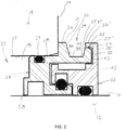
Figure 2 is an enlarged view of the bearing isolator seal at a top or 12 o'clock position. -
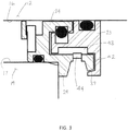
Figure 3 is a cross-section of the bearing isolator seal at the bottom or 6 o'clock position. - Certain terminology will be used in the following description for convenience and reference only, and will not be limiting. For example, the words "upwardly", "downwardly", "rightwardly" and "leftwardly" will refer to directions in the drawings to which reference is made. The words "inwardly" and "outwardly" will refer to directions toward and away from, respectively, the geometric center of the arrangement and designated parts thereof. Said terminology will include the words specifically mentioned, derivatives thereof, and words of similar import.
- Referring to
Figure 1 , abearing isolator seal 10 of the present invention is shown mounted to anequipment shaft 12 and anequipment housing 14. - The
shaft 12 rotates about a shaft axis 15 and has an annular,outer shaft surface 16 which faces radially outwardly. Theequipment housing 14 has an inward facingpassage surface 17 disposed in opposing, radially spaced relation from theshaft surface 16, wherein thepassage surface 17 defines a passage 18 through which theshaft 12 extends axially. The passage 18 opens axially from ahousing end face 19, and essentially defines a bearing cavity orchamber 20 in which abearing unit 21 is installed. Thebearing unit 21 may be any type of bearing suitable to rotatably support theshaft 12 with examples being listed above. - Generally, the
bearing isolator assembly 10 includes a shaft-mountedrotor 23 and housing-mountedstator 24 which are relatively rotatable relative to each other. As to thestator 24, thestator 24 stationarily mounts within the open end of the passage 18 on theequipment housing 14 and has a first, inboardradial flange 26 which abuts against thehousing end face 19. Therotor 23 in turn mounts to theshaft 12 and rotates therewith. Therotor 23 andstator 24 have closely spaced surfaces which prevent or limit the egress of various types of contaminants, like high velocity water spray, to protect thebearing 21. - The
rotor 23 andstator 24 are formed as annular rings which surround theshaft 12 withFigures 2 and3 showing the cross-sectional shape at the top, 12 o'clock position, and the bottom, 6 o'clock position on these annular rings. - Referring to
Figure 2 , thestator 24 has aninboard portion 28 that fits within the passage 18 and is sealed there against by an O-ring 29. The inboardradial flange 26 projects radially to define anouter flange surface 31 at the outside diameter (OD). Theradial flange 26 abuts against thehousing end face 19. - The
stator 24 then extends axially and includes an outboard radial flange 32 which is spaced axially from the inboardradial flange 26 and extends radially, outwardly to a smaller extent than the inboardradial flange 26 so as to define a terminalouter surface 33. These axially-spacedradial flanges 26 and 32 thereby define anannular groove 34, which opens radially outwardly and is bounded by inboard and outboard groove side faces 36 and 37 and a groove bottom face 38. - The groove bottom face 38 is generally parallel to the shaft axis 15 (
Figure 1 ), while the groove side faces 36 and 37 are oriented at non-perpendicular, obtuse angles 38A and 38B relative to the shaft axis 15 and the groove bottom face 38. Each of the groove side faces 36 and 37 is oriented such that the obtuse angles 38A and 38B are at an angle of 95 to 135 degrees relative to the bottom groove surface 38 and the shaft axis 15 and preferably is oriented at 105 degrees. Preferably, eachgroove side face - Also, the outer
terminal face 33 of the outboard radial flange 32 is angled relative to the shaft axis 15 as will be discussed in more detail herein. - The
rotor 23 includes aradial projection 35 which extends outwardly close to the outboard radial projection 32 on thestator 24, and therotor 23 then includes an axial projection 36' which turns in the inboard direction, towards thehousing 14 so as to lie closely adjacent to theterminal surface 33 of the stator radial flange 32. The radially outward facingsurface 33 on the stator radial flange 32 and an opposing inward facing surface 37' on the rotor axial projection 36' define anentrance passageway 39 which are slightly separated to allow relative rotation between thestator 24 androtor 23 but sufficiently close to substantially restrict entry of contaminants between the opposed, relatively-movingsurfaces 33 and 37'. - The rotor axial projection 36' also has an end face 40 which is generally perpendicular to the shaft axis 15 but is skewed or oriented at an angle relative to the adjacent
groove side face 37. These skewed faces 37 and 40 help redirect fluid flow past thepassageway 39 and out of thegroove 34. - Referencing the
entrance passageway 39, theentrance passageway 39 and the opposingsurfaces 33 and 37' are formed at an angle relative to the shaft axis 15. As such, theentrance passageway 39 is at an angle of 5-45 degrees and preferably at an acute angle of 15 degrees relative to the shaft axis 15. This passage angle enhances the centrifugal effects caused by the relative movement of the surface 37' relative to surface 33 during shaft rotation to eject any contaminants from the entrance of thepassageway 39 and also assist with draining at the bottom or 6 o'clock position (Figure 3 ) of therotor 23 andstator 24 when theshaft 12 is not rotating. - The
entrance passageway 39 also communicates with aninterface passage 42 which extends radially inwardly and is formed between opposed, closely-adjacent surfaces of therotor 23 andstator 24. Thispassage 42 in turn opens into acollection groove 43 that collects any contaminants that make it into theentrance passageway 39. Thecollection groove 43 surrounds therotor 23 and at the bottom, 6 o'clock position shown inFigure 3 , thegroove 43 empties into anoutlet port 44 formed in thestator 24. - In view of the foregoing, the improved
bearing isolator seal 10 includes an improved geometry which is believed to result in improved exclusion of contaminants, particularly in high velocity water spray from the bearingcavity 21 of the rotating equipment. This design exhibits a combination of features which combine to provide improved performance. - For example, the
annular stator groove 34 has the angled side surfaces 36 and 37 on the inboard and outboard sides and no right angles. As such, these angled side surfaces 36 and 37 redirect incoming contaminants and high velocity spray and reduce the possibility of the incoming contaminant flow entering the restricted flow path defined by theentrance passageway 39. These obtuse angles help to redirect the incoming high velocity spray radially outwardly out of thegroove 34 to minimize the amount of spray and other contaminants which can enter thepassageway 39 between therotor 23 andstator 24. - It is preferred that both
surfaces groove 34. This is believed to enhance the deflection and flow of spray out of thegroove 34 and reduce the tendency for such spray to enter thepassageway 39. - Further, the inboard
radial flange 26 defines anadditional deflection surface 31 within the spray zone next to thegroove 34. Preferably, the outer diameter of theradial flange 26 is greater than the diameter of the outboard radial flange 32 but is closely proximate to or greater than the outer diameter defined by the rotor axial projection 36'. If the diameter of thesurface 31 is too large or too small, the fluid spray will merely deflect downwardly into thegroove 34, rather than having the partial deflection of spray outwardly which is affected by thedeflection surface 31. As such, thedeflection surface 31 provides an additional surface that can help to redirect some of the spray outwardly and away from theentrance passageway 39. - Also, the angled interface between the stator and rotor surfaces 33 and 37' which define the
entrance passageway 39 thereby increases the rotational effects of exclusion during shaft rotation. This angled feature of theentrance passageway 39 also assists in the draining of contaminants from the bottom of the bearing isolator seal, even in a static condition while theshaft 12 is not rotating. - Although a particular preferred embodiment of the invention has been disclosed in detail for illustrative purposes, it will be recognized that variations or modifications of the disclosed apparatus, including the rearrangement of parts, lie within the scope of the present invention, the latter being limited by the appended claims.
Claims (16)
- A bearing isolator seal (10) for sealing a bearing cavity (20) between an equipment housing (14) and a rotatable shaft (12), said bearing isolator seal (10) comprising: a housing-mountable stator (24) having a mounting portion (28) engagable with an equipment housing (14), an inboard radial flange (26) located for axial abutment against an exterior end face (19) of an equipment housing (14),
and an outboard radial flange (32) spaced axially from said inboard radial flange (26), said inboard and outboard radial flanges (26, 32) being axially spaced apart so as to define respective first (36) and second (37) groove side faces and a groove bottom face (38) extending axially therebetween to define an annular groove (34) opening radially outwardly, a shaft-mountable, rotatable rotor (23) wherein said rotor and stator (24) have closely spaced, opposing passageway surfaces (37', 33) which define an entrance passageway (39) between an outer stator face (33) of said outboard radial flange (32) and an opposing inner rotor face (37') on said rotor (23), characterised by each of said first (36) and second (37) groove side faces being inclined at respective obtuse angles (38A, 38B) relative to said bottom groove face (38); and said entrance passageway (39) extending at an angle relative to a shaft axis (15) to which said bearing isolator seal (10) is mountable, said entrance passageway (39) opening toward said inboard radial flange (26) of said stator at a passage angle, wherein said obtuse angles (38A, 38B) of said first (36) and second (37) groove side faces deflecting fluid away from said entrance passageway (39) and said passage angle of said entrance passageway increases centrifugal exclusion of fluids during rotation of said rotor (23). - The bearing isolator seal according to Claim 1,
wherein said groove bottom face (38) is generally parallel to a shaft axis (15) while said groove side faces (36, 37) have are oriented at said obtuse angles (38A, 38B) non-perpendicular said shaft axis. - The bearing isolator seal according to Claim 1,
wherein each of said groove side faces (36, 37) are oriented such that said obtuse angles (38A, 38B) are at an angle of 95 to 135 degrees relative to said bottom groove surface (38). - The bearing isolator seal according to Claim 3,
wherein at least one of said obtuse angles is oriented at 105 degrees relative to said bottom groove surface. - The bearing isolator seal according to Claim 1,
wherein said outboard radial flange (32) is spaced axially from said inboard radial flange (26) and extends radially, outwardly so as to terminate at an outer stator surface which defines one said passage surface. - The bearing isolator seal according to Claim 5,
wherein said rotor includes a rotor axial projection (36') which extends in an inboard direction toward said inboard radial flange (26) so as to lie closely adjacent to said outer stator surface of said second radial flange (32) of said stator and define said entrance passageway therebetween. - The bearing isolator seal according to Claim 6,
wherein said rotor axial projection (36') comprises an inner rotor surface (37') which defines the other of said passage surfaces wherein said outer stator surface (33) and said inner rotor surface define said entrance passageway, said outer stator surface and said inner rotor surface being closely adjacent but separated to allow relative rotation between said stator and said rotor while restricting entrance of fluids therein. - The bearing isolator seal according to Claim 7,
wherein said rotor axial projection (36') has a rotor end face which is perpendicular to said shaft axis but is skewed relative to an adjacent one of said groove side faces to facilitate redirection of fluid flow past said entrance passageway. - The bearing isolator seal according to Claim 7,
wherein said entrance passageway extends at a passage angle of 5-45 degrees relative to a shaft axis. - The bearing isolator seal according to Claim 9,
wherein said passage angle of said entrance passageway is at an acute angle of about 15 degrees relative to said shaft axis. - The bearing isolator seal according to Claim 7,
wherein said entrance passageway extends at said passage angle enhances centrifugal effects caused by the relative movement of the passage surfaces during rotation of said rotor to eject contaminants from said entrance passageway and also assist with draining of contaminants at a bottom 6 o'clock position of said rotor and stator. - The bearing isolator seal according to Claim 11,
wherein said stator includes a drain port (44) at said bottom 6 o'clock position which is in fluid communication with said entrance passageway. - The bearing isolator seal according to Claim 1,
wherein said entrance passageway extends at a passage angle of 45 degrees or less which enhances centrifugal effects caused by the relative movement of the passage surfaces during rotation of said rotor to eject contaminants from said entrance passageway and also assists with draining of contaminants at a bottom 6 o'clock position of said rotor and stator. - The bearing isolator seal according to Claim 13,
wherein said stator includes a drain port (44) at said bottom 6 o'clock position which is in fluid communication with said entrance passageway. - The bearing isolator seal according to Claim 1,
wherein said rotor (23) includes a rotor axial projection (36') which extends in an inboard direction toward said inboard radial flange (26) so as to lie closely adjacent to said outer stator surface of said outboard radial flange (32) of said stator and define said entrance passageway therebetween, said inboard radial flange (26) defines an additional deflection surface at an outer diameter similar to an outer diameter of said rotor axial projection. - The bearing isolator seal according to Claim 1,
wherein said outer diameter of said inboard radial flange (26) is greater than an outer diameter of the outboard radial flange (32) but is closely proximate to or greater than said outer diameter defined by said rotor axial projection.
Applications Claiming Priority (2)
| Application Number | Priority Date | Filing Date | Title |
|---|---|---|---|
| US201461925894P | 2014-01-10 | 2014-01-10 | |
| PCT/US2015/010605 WO2015105964A1 (en) | 2014-01-10 | 2015-01-08 | Bearing isolator seal for rotating shaft |
Publications (2)
| Publication Number | Publication Date |
|---|---|
| EP3092427A1 EP3092427A1 (en) | 2016-11-16 |
| EP3092427B1 true EP3092427B1 (en) | 2018-03-14 |
Family
ID=52434968
Family Applications (1)
| Application Number | Title | Priority Date | Filing Date |
|---|---|---|---|
| EP15701867.2A Active EP3092427B1 (en) | 2014-01-10 | 2015-01-08 | Bearing isolator seal for rotating shaft |
Country Status (4)
| Country | Link |
|---|---|
| US (1) | US9140366B2 (en) |
| EP (1) | EP3092427B1 (en) |
| CA (1) | CA2936444C (en) |
| WO (1) | WO2015105964A1 (en) |
Families Citing this family (9)
| Publication number | Priority date | Publication date | Assignee | Title |
|---|---|---|---|---|
| WO2013126229A2 (en) * | 2012-02-10 | 2013-08-29 | Orion Engineered Seals, Llc | Labyrinth seal |
| MX380065B (en) * | 2014-12-08 | 2025-03-11 | Flowserve Pte Ltd | Bearing Seal with Static Sealing Tapered O-Ring Interface |
| MX375605B (en) * | 2014-12-18 | 2025-03-06 | Flowserve Pte Ltd | BEARING ISOLATING SEAL WITH IMPROVED ROTOR UNIT COUPLING |
| DE102016204007A1 (en) | 2016-01-26 | 2017-07-27 | Siemens Aktiengesellschaft | poetry |
| US10337618B2 (en) * | 2017-04-07 | 2019-07-02 | Gm Global Technology Operations Llc. | Seal assembly for a steering gear input shaft |
| US11002792B2 (en) | 2018-12-21 | 2021-05-11 | Itt Manufacturing Enterprises Llc | Machine slip and direction sensing using flux gate sensor |
| CN111412289B (en) * | 2020-03-26 | 2022-07-05 | 青岛中加特电气股份有限公司 | Sealing device for rotary machine |
| US11815100B2 (en) * | 2020-04-01 | 2023-11-14 | Billy Dean Watson | Fluid leak diverter |
| WO2023100156A1 (en) | 2021-12-03 | 2023-06-08 | MAE Technical Advisory LLC | Self-curing thermohydrodynamic seal |
Family Cites Families (23)
| Publication number | Priority date | Publication date | Assignee | Title |
|---|---|---|---|---|
| GB2041111A (en) | 1978-11-11 | 1980-09-03 | Universal Conveyor Co Ltd | Improvements in rollers |
| IT1187539B (en) | 1985-02-28 | 1987-12-23 | Danieli Off Mecc | LABYRINTH SEAL |
| US4743034A (en) | 1987-03-27 | 1988-05-10 | Durametallic Corporation | Labyrinth bearing protector seal |
| JPH02116068A (en) | 1988-10-24 | 1990-04-27 | Canon Inc | head load mechanism |
| JPH03120301A (en) | 1989-10-03 | 1991-05-22 | Toyota Motor Corp | Powder metallurgical method for aluminum alloy |
| JPH06250378A (en) | 1993-02-24 | 1994-09-09 | Nikon Corp | Exposure method and photomask used in the same |
| US5522601A (en) * | 1994-01-18 | 1996-06-04 | Goulds Pumps, Incorporated | Locking labyrinth sealing assembly |
| US5498006A (en) * | 1995-05-12 | 1996-03-12 | Inpro Companies, Inc. | Pinned unitary bearing seal |
| CA2215174A1 (en) | 1996-09-11 | 1998-03-11 | David R. Mundy | Seal for bearing housing |
| JPH11108202A (en) | 1997-09-30 | 1999-04-20 | Tokuo Okabayashi | Labyrinth seal |
| US6419233B2 (en) * | 1998-08-25 | 2002-07-16 | Isotech Of Illinois, Inc. | Shaft seal assembly |
| US7052014B1 (en) | 1999-02-04 | 2006-05-30 | Orlowski David C | Snap together bearing isolator |
| DE20202260U1 (en) | 2002-02-14 | 2002-04-25 | Deckel Maho Pfronten GmbH, 87459 Pfronten | High-speed spindle unit for machine tools |
| CN100412425C (en) | 2002-09-30 | 2008-08-20 | 卡罗克密封技术公司 | Seal assembly for sealing a rotating shaft and a bearing housing and method of assembling the same |
| US7604239B2 (en) | 2002-09-30 | 2009-10-20 | Garlock Scaling Technologies LLC | Split bearing isolator and a method for assembling seal |
| US20110204734A1 (en) * | 2005-06-25 | 2011-08-25 | Orlowski David C | Motor Grounding Seal |
| GB0607513D0 (en) * | 2006-04-18 | 2006-05-24 | Aes Eng Ltd | Bearing protector for axial shaft movement |
| GB0607623D0 (en) * | 2006-04-19 | 2006-05-31 | Aes Eng Ltd | Bearing protector with air pumps |
| GB0612304D0 (en) * | 2006-06-21 | 2006-08-02 | Aes Eng Ltd | Bearing seal |
| DE102010064419B3 (en) | 2009-03-03 | 2012-11-22 | Sew-Eurodrive Gmbh & Co. Kg | Arrangement for non-contact sealing of a rotatably mounted shaft to a housing and gearbox |
| JP5899933B2 (en) | 2012-01-06 | 2016-04-06 | 日本精工株式会社 | Spindle device |
| WO2013100099A1 (en) | 2011-12-27 | 2013-07-04 | 日本精工株式会社 | Spindle device |
| US8613556B2 (en) | 2012-02-24 | 2013-12-24 | Ntn Usa Corporation | Bearing protection system |
-
2015
- 2015-01-08 US US14/592,453 patent/US9140366B2/en active Active
- 2015-01-08 EP EP15701867.2A patent/EP3092427B1/en active Active
- 2015-01-08 WO PCT/US2015/010605 patent/WO2015105964A1/en not_active Ceased
- 2015-01-08 CA CA2936444A patent/CA2936444C/en active Active
Also Published As
| Publication number | Publication date |
|---|---|
| US20150198252A1 (en) | 2015-07-16 |
| CA2936444A1 (en) | 2015-07-16 |
| CA2936444C (en) | 2020-03-24 |
| WO2015105964A1 (en) | 2015-07-16 |
| EP3092427A1 (en) | 2016-11-16 |
| US9140366B2 (en) | 2015-09-22 |
Similar Documents
| Publication | Publication Date | Title |
|---|---|---|
| CA2936444C (en) | Bearing isolator seal for rotating shaft | |
| US5290047A (en) | Bearing protection device | |
| US4743034A (en) | Labyrinth bearing protector seal | |
| US4890941A (en) | Bearing protector with slinger ring | |
| US6247702B1 (en) | Bearing shaft seal | |
| US6471215B1 (en) | Labyrinth sealing device having a grease purgeable system | |
| EP3286462B1 (en) | Shaft seal assembly | |
| ES2338617T3 (en) | ASSEMBLY OF BOARD FOR IMPROVED TREE. | |
| US4844480A (en) | Pressure sensitive shaft sealing ring | |
| US6367807B1 (en) | Labyrinth seal assembly | |
| US10267364B2 (en) | Device for lubricating an antifriction bearing of an electric motor | |
| US20160208857A1 (en) | Bearing isolator | |
| US9249884B2 (en) | Pressure resistant static and dynamic seal assembly and method | |
| CA2593260C (en) | Bearing housing seal system for centrifugal pumps | |
| WO2015180928A1 (en) | Radial seal with contacting and non-contacting portions | |
| CN108087556B (en) | Cassette sealing structure | |
| EP1391613B1 (en) | Apparatus for sealing a water pump bearing | |
| RU2688125C1 (en) | Sealing device, in particular, for protection against contamination with external substances | |
| US7748715B2 (en) | Bearing seal | |
| US6726214B2 (en) | Wrap-around severe splash seal | |
| US7789395B2 (en) | Bearing protector | |
| CN107681809B (en) | Sealing device suitable for mowing motor, mowing motor and mowing machine | |
| US20080044279A1 (en) | Adaptor Frame | |
| US6336637B1 (en) | Sever splash seal | |
| JPH09196186A (en) | Labyrinth seal device |
Legal Events
| Date | Code | Title | Description |
|---|---|---|---|
| PUAI | Public reference made under article 153(3) epc to a published international application that has entered the european phase |
Free format text: ORIGINAL CODE: 0009012 |
|
| 17P | Request for examination filed |
Effective date: 20160809 |
|
| AK | Designated contracting states |
Kind code of ref document: A1 Designated state(s): AL AT BE BG CH CY CZ DE DK EE ES FI FR GB GR HR HU IE IS IT LI LT LU LV MC MK MT NL NO PL PT RO RS SE SI SK SM TR |
|
| AX | Request for extension of the european patent |
Extension state: BA ME |
|
| DAX | Request for extension of the european patent (deleted) | ||
| GRAP | Despatch of communication of intention to grant a patent |
Free format text: ORIGINAL CODE: EPIDOSNIGR1 |
|
| STAA | Information on the status of an ep patent application or granted ep patent |
Free format text: STATUS: GRANT OF PATENT IS INTENDED |
|
| INTG | Intention to grant announced |
Effective date: 20170914 |
|
| GRAS | Grant fee paid |
Free format text: ORIGINAL CODE: EPIDOSNIGR3 |
|
| GRAA | (expected) grant |
Free format text: ORIGINAL CODE: 0009210 |
|
| STAA | Information on the status of an ep patent application or granted ep patent |
Free format text: STATUS: THE PATENT HAS BEEN GRANTED |
|
| AK | Designated contracting states |
Kind code of ref document: B1 Designated state(s): AL AT BE BG CH CY CZ DE DK EE ES FI FR GB GR HR HU IE IS IT LI LT LU LV MC MK MT NL NO PL PT RO RS SE SI SK SM TR |
|
| REG | Reference to a national code |
Ref country code: GB Ref legal event code: FG4D |
|
| REG | Reference to a national code |
Ref country code: CH Ref legal event code: EP Ref country code: AT Ref legal event code: REF Ref document number: 979225 Country of ref document: AT Kind code of ref document: T Effective date: 20180315 |
|
| REG | Reference to a national code |
Ref country code: IE Ref legal event code: FG4D |
|
| REG | Reference to a national code |
Ref country code: DE Ref legal event code: R096 Ref document number: 602015008777 Country of ref document: DE |
|
| REG | Reference to a national code |
Ref country code: NL Ref legal event code: FP |
|
| REG | Reference to a national code |
Ref country code: LT Ref legal event code: MG4D |
|
| PG25 | Lapsed in a contracting state [announced via postgrant information from national office to epo] |
Ref country code: CY Free format text: LAPSE BECAUSE OF FAILURE TO SUBMIT A TRANSLATION OF THE DESCRIPTION OR TO PAY THE FEE WITHIN THE PRESCRIBED TIME-LIMIT Effective date: 20180314 Ref country code: LT Free format text: LAPSE BECAUSE OF FAILURE TO SUBMIT A TRANSLATION OF THE DESCRIPTION OR TO PAY THE FEE WITHIN THE PRESCRIBED TIME-LIMIT Effective date: 20180314 Ref country code: HR Free format text: LAPSE BECAUSE OF FAILURE TO SUBMIT A TRANSLATION OF THE DESCRIPTION OR TO PAY THE FEE WITHIN THE PRESCRIBED TIME-LIMIT Effective date: 20180314 Ref country code: NO Free format text: LAPSE BECAUSE OF FAILURE TO SUBMIT A TRANSLATION OF THE DESCRIPTION OR TO PAY THE FEE WITHIN THE PRESCRIBED TIME-LIMIT Effective date: 20180614 Ref country code: FI Free format text: LAPSE BECAUSE OF FAILURE TO SUBMIT A TRANSLATION OF THE DESCRIPTION OR TO PAY THE FEE WITHIN THE PRESCRIBED TIME-LIMIT Effective date: 20180314 |
|
| REG | Reference to a national code |
Ref country code: AT Ref legal event code: MK05 Ref document number: 979225 Country of ref document: AT Kind code of ref document: T Effective date: 20180314 |
|
| PG25 | Lapsed in a contracting state [announced via postgrant information from national office to epo] |
Ref country code: SE Free format text: LAPSE BECAUSE OF FAILURE TO SUBMIT A TRANSLATION OF THE DESCRIPTION OR TO PAY THE FEE WITHIN THE PRESCRIBED TIME-LIMIT Effective date: 20180314 Ref country code: RS Free format text: LAPSE BECAUSE OF FAILURE TO SUBMIT A TRANSLATION OF THE DESCRIPTION OR TO PAY THE FEE WITHIN THE PRESCRIBED TIME-LIMIT Effective date: 20180314 Ref country code: LV Free format text: LAPSE BECAUSE OF FAILURE TO SUBMIT A TRANSLATION OF THE DESCRIPTION OR TO PAY THE FEE WITHIN THE PRESCRIBED TIME-LIMIT Effective date: 20180314 Ref country code: GR Free format text: LAPSE BECAUSE OF FAILURE TO SUBMIT A TRANSLATION OF THE DESCRIPTION OR TO PAY THE FEE WITHIN THE PRESCRIBED TIME-LIMIT Effective date: 20180615 Ref country code: BG Free format text: LAPSE BECAUSE OF FAILURE TO SUBMIT A TRANSLATION OF THE DESCRIPTION OR TO PAY THE FEE WITHIN THE PRESCRIBED TIME-LIMIT Effective date: 20180614 |
|
| PG25 | Lapsed in a contracting state [announced via postgrant information from national office to epo] |
Ref country code: RO Free format text: LAPSE BECAUSE OF FAILURE TO SUBMIT A TRANSLATION OF THE DESCRIPTION OR TO PAY THE FEE WITHIN THE PRESCRIBED TIME-LIMIT Effective date: 20180314 Ref country code: PL Free format text: LAPSE BECAUSE OF FAILURE TO SUBMIT A TRANSLATION OF THE DESCRIPTION OR TO PAY THE FEE WITHIN THE PRESCRIBED TIME-LIMIT Effective date: 20180314 Ref country code: AL Free format text: LAPSE BECAUSE OF FAILURE TO SUBMIT A TRANSLATION OF THE DESCRIPTION OR TO PAY THE FEE WITHIN THE PRESCRIBED TIME-LIMIT Effective date: 20180314 Ref country code: ES Free format text: LAPSE BECAUSE OF FAILURE TO SUBMIT A TRANSLATION OF THE DESCRIPTION OR TO PAY THE FEE WITHIN THE PRESCRIBED TIME-LIMIT Effective date: 20180314 Ref country code: EE Free format text: LAPSE BECAUSE OF FAILURE TO SUBMIT A TRANSLATION OF THE DESCRIPTION OR TO PAY THE FEE WITHIN THE PRESCRIBED TIME-LIMIT Effective date: 20180314 |
|
| PG25 | Lapsed in a contracting state [announced via postgrant information from national office to epo] |
Ref country code: CZ Free format text: LAPSE BECAUSE OF FAILURE TO SUBMIT A TRANSLATION OF THE DESCRIPTION OR TO PAY THE FEE WITHIN THE PRESCRIBED TIME-LIMIT Effective date: 20180314 Ref country code: AT Free format text: LAPSE BECAUSE OF FAILURE TO SUBMIT A TRANSLATION OF THE DESCRIPTION OR TO PAY THE FEE WITHIN THE PRESCRIBED TIME-LIMIT Effective date: 20180314 Ref country code: SM Free format text: LAPSE BECAUSE OF FAILURE TO SUBMIT A TRANSLATION OF THE DESCRIPTION OR TO PAY THE FEE WITHIN THE PRESCRIBED TIME-LIMIT Effective date: 20180314 Ref country code: SK Free format text: LAPSE BECAUSE OF FAILURE TO SUBMIT A TRANSLATION OF THE DESCRIPTION OR TO PAY THE FEE WITHIN THE PRESCRIBED TIME-LIMIT Effective date: 20180314 |
|
| REG | Reference to a national code |
Ref country code: DE Ref legal event code: R097 Ref document number: 602015008777 Country of ref document: DE |
|
| PG25 | Lapsed in a contracting state [announced via postgrant information from national office to epo] |
Ref country code: PT Free format text: LAPSE BECAUSE OF FAILURE TO SUBMIT A TRANSLATION OF THE DESCRIPTION OR TO PAY THE FEE WITHIN THE PRESCRIBED TIME-LIMIT Effective date: 20180716 |
|
| PLBE | No opposition filed within time limit |
Free format text: ORIGINAL CODE: 0009261 |
|
| STAA | Information on the status of an ep patent application or granted ep patent |
Free format text: STATUS: NO OPPOSITION FILED WITHIN TIME LIMIT |
|
| PG25 | Lapsed in a contracting state [announced via postgrant information from national office to epo] |
Ref country code: DK Free format text: LAPSE BECAUSE OF FAILURE TO SUBMIT A TRANSLATION OF THE DESCRIPTION OR TO PAY THE FEE WITHIN THE PRESCRIBED TIME-LIMIT Effective date: 20180314 |
|
| 26N | No opposition filed |
Effective date: 20181217 |
|
| PG25 | Lapsed in a contracting state [announced via postgrant information from national office to epo] |
Ref country code: SI Free format text: LAPSE BECAUSE OF FAILURE TO SUBMIT A TRANSLATION OF THE DESCRIPTION OR TO PAY THE FEE WITHIN THE PRESCRIBED TIME-LIMIT Effective date: 20180314 Ref country code: IT Free format text: LAPSE BECAUSE OF FAILURE TO SUBMIT A TRANSLATION OF THE DESCRIPTION OR TO PAY THE FEE WITHIN THE PRESCRIBED TIME-LIMIT Effective date: 20180314 |
|
| PG25 | Lapsed in a contracting state [announced via postgrant information from national office to epo] |
Ref country code: MC Free format text: LAPSE BECAUSE OF FAILURE TO SUBMIT A TRANSLATION OF THE DESCRIPTION OR TO PAY THE FEE WITHIN THE PRESCRIBED TIME-LIMIT Effective date: 20180314 |
|
| REG | Reference to a national code |
Ref country code: CH Ref legal event code: PL |
|
| PG25 | Lapsed in a contracting state [announced via postgrant information from national office to epo] |
Ref country code: LU Free format text: LAPSE BECAUSE OF NON-PAYMENT OF DUE FEES Effective date: 20190108 |
|
| REG | Reference to a national code |
Ref country code: BE Ref legal event code: MM Effective date: 20190131 |
|
| REG | Reference to a national code |
Ref country code: IE Ref legal event code: MM4A |
|
| PG25 | Lapsed in a contracting state [announced via postgrant information from national office to epo] |
Ref country code: BE Free format text: LAPSE BECAUSE OF NON-PAYMENT OF DUE FEES Effective date: 20190131 |
|
| PG25 | Lapsed in a contracting state [announced via postgrant information from national office to epo] |
Ref country code: CH Free format text: LAPSE BECAUSE OF NON-PAYMENT OF DUE FEES Effective date: 20190131 Ref country code: LI Free format text: LAPSE BECAUSE OF NON-PAYMENT OF DUE FEES Effective date: 20190131 |
|
| PG25 | Lapsed in a contracting state [announced via postgrant information from national office to epo] |
Ref country code: IE Free format text: LAPSE BECAUSE OF NON-PAYMENT OF DUE FEES Effective date: 20190108 |
|
| PG25 | Lapsed in a contracting state [announced via postgrant information from national office to epo] |
Ref country code: TR Free format text: LAPSE BECAUSE OF FAILURE TO SUBMIT A TRANSLATION OF THE DESCRIPTION OR TO PAY THE FEE WITHIN THE PRESCRIBED TIME-LIMIT Effective date: 20180314 |
|
| PG25 | Lapsed in a contracting state [announced via postgrant information from national office to epo] |
Ref country code: MT Free format text: LAPSE BECAUSE OF NON-PAYMENT OF DUE FEES Effective date: 20190108 |
|
| PG25 | Lapsed in a contracting state [announced via postgrant information from national office to epo] |
Ref country code: IS Free format text: LAPSE BECAUSE OF FAILURE TO SUBMIT A TRANSLATION OF THE DESCRIPTION OR TO PAY THE FEE WITHIN THE PRESCRIBED TIME-LIMIT Effective date: 20180714 |
|
| PG25 | Lapsed in a contracting state [announced via postgrant information from national office to epo] |
Ref country code: HU Free format text: LAPSE BECAUSE OF FAILURE TO SUBMIT A TRANSLATION OF THE DESCRIPTION OR TO PAY THE FEE WITHIN THE PRESCRIBED TIME-LIMIT; INVALID AB INITIO Effective date: 20150108 |
|
| PG25 | Lapsed in a contracting state [announced via postgrant information from national office to epo] |
Ref country code: MK Free format text: LAPSE BECAUSE OF FAILURE TO SUBMIT A TRANSLATION OF THE DESCRIPTION OR TO PAY THE FEE WITHIN THE PRESCRIBED TIME-LIMIT Effective date: 20180314 |
|
| PGFP | Annual fee paid to national office [announced via postgrant information from national office to epo] |
Ref country code: NL Payment date: 20260126 Year of fee payment: 12 |
|
| PGFP | Annual fee paid to national office [announced via postgrant information from national office to epo] |
Ref country code: GB Payment date: 20260127 Year of fee payment: 12 |
|
| PGFP | Annual fee paid to national office [announced via postgrant information from national office to epo] |
Ref country code: DE Payment date: 20260128 Year of fee payment: 12 |
|
| PGFP | Annual fee paid to national office [announced via postgrant information from national office to epo] |
Ref country code: FR Payment date: 20260126 Year of fee payment: 12 |