EP3092381B2 - Modular mixer for exhaust assembly - Google Patents
Modular mixer for exhaust assembly Download PDFInfo
- Publication number
- EP3092381B2 EP3092381B2 EP14878138.8A EP14878138A EP3092381B2 EP 3092381 B2 EP3092381 B2 EP 3092381B2 EP 14878138 A EP14878138 A EP 14878138A EP 3092381 B2 EP3092381 B2 EP 3092381B2
- Authority
- EP
- European Patent Office
- Prior art keywords
- exhaust
- exhaust component
- mixer
- connection interfaces
- connection
- Prior art date
- Legal status (The legal status is an assumption and is not a legal conclusion. Google has not performed a legal analysis and makes no representation as to the accuracy of the status listed.)
- Active
Links
- 239000003054 catalyst Substances 0.000 claims description 11
- 230000008878 coupling Effects 0.000 claims description 7
- 238000010168 coupling process Methods 0.000 claims description 7
- 238000005859 coupling reaction Methods 0.000 claims description 7
- 239000012530 fluid Substances 0.000 claims description 6
- 238000000034 method Methods 0.000 claims description 6
- 230000007704 transition Effects 0.000 claims 2
- 239000007789 gas Substances 0.000 description 10
- 238000004806 packaging method and process Methods 0.000 description 5
- 238000010531 catalytic reduction reaction Methods 0.000 description 3
- 239000003638 chemical reducing agent Substances 0.000 description 3
- 230000001419 dependent effect Effects 0.000 description 3
- 210000003739 neck Anatomy 0.000 description 3
- XSQUKJJJFZCRTK-UHFFFAOYSA-N Urea Chemical compound NC(N)=O XSQUKJJJFZCRTK-UHFFFAOYSA-N 0.000 description 2
- 239000004202 carbamide Substances 0.000 description 2
- 238000004891 communication Methods 0.000 description 2
- 230000003647 oxidation Effects 0.000 description 2
- 238000007254 oxidation reaction Methods 0.000 description 2
- 238000006722 reduction reaction Methods 0.000 description 2
- 238000011144 upstream manufacturing Methods 0.000 description 2
- 239000007864 aqueous solution Substances 0.000 description 1
- 238000005219 brazing Methods 0.000 description 1
- 239000000446 fuel Substances 0.000 description 1
- 238000009434 installation Methods 0.000 description 1
- 230000013011 mating Effects 0.000 description 1
- 239000000203 mixture Substances 0.000 description 1
- 238000012986 modification Methods 0.000 description 1
- 230000004048 modification Effects 0.000 description 1
- 238000003466 welding Methods 0.000 description 1
Images

Classifications
-
- F—MECHANICAL ENGINEERING; LIGHTING; HEATING; WEAPONS; BLASTING
- F01—MACHINES OR ENGINES IN GENERAL; ENGINE PLANTS IN GENERAL; STEAM ENGINES
- F01N—GAS-FLOW SILENCERS OR EXHAUST APPARATUS FOR MACHINES OR ENGINES IN GENERAL; GAS-FLOW SILENCERS OR EXHAUST APPARATUS FOR INTERNAL COMBUSTION ENGINES
- F01N3/00—Exhaust or silencing apparatus having means for purifying, rendering innocuous, or otherwise treating exhaust
- F01N3/08—Exhaust or silencing apparatus having means for purifying, rendering innocuous, or otherwise treating exhaust for rendering innocuous
- F01N3/10—Exhaust or silencing apparatus having means for purifying, rendering innocuous, or otherwise treating exhaust for rendering innocuous by thermal or catalytic conversion of noxious components of exhaust
- F01N3/24—Exhaust or silencing apparatus having means for purifying, rendering innocuous, or otherwise treating exhaust for rendering innocuous by thermal or catalytic conversion of noxious components of exhaust characterised by constructional aspects of converting apparatus
- F01N3/28—Construction of catalytic reactors
- F01N3/2892—Exhaust flow directors or the like, e.g. upstream of catalytic device
-
- F—MECHANICAL ENGINEERING; LIGHTING; HEATING; WEAPONS; BLASTING
- F01—MACHINES OR ENGINES IN GENERAL; ENGINE PLANTS IN GENERAL; STEAM ENGINES
- F01N—GAS-FLOW SILENCERS OR EXHAUST APPARATUS FOR MACHINES OR ENGINES IN GENERAL; GAS-FLOW SILENCERS OR EXHAUST APPARATUS FOR INTERNAL COMBUSTION ENGINES
- F01N13/00—Exhaust or silencing apparatus characterised by constructional features ; Exhaust or silencing apparatus, or parts thereof, having pertinent characteristics not provided for in, or of interest apart from, groups F01N1/00 - F01N5/00, F01N9/00, F01N11/00
- F01N13/009—Exhaust or silencing apparatus characterised by constructional features ; Exhaust or silencing apparatus, or parts thereof, having pertinent characteristics not provided for in, or of interest apart from, groups F01N1/00 - F01N5/00, F01N9/00, F01N11/00 having two or more separate purifying devices arranged in series
-
- F—MECHANICAL ENGINEERING; LIGHTING; HEATING; WEAPONS; BLASTING
- F01—MACHINES OR ENGINES IN GENERAL; ENGINE PLANTS IN GENERAL; STEAM ENGINES
- F01N—GAS-FLOW SILENCERS OR EXHAUST APPARATUS FOR MACHINES OR ENGINES IN GENERAL; GAS-FLOW SILENCERS OR EXHAUST APPARATUS FOR INTERNAL COMBUSTION ENGINES
- F01N13/00—Exhaust or silencing apparatus characterised by constructional features ; Exhaust or silencing apparatus, or parts thereof, having pertinent characteristics not provided for in, or of interest apart from, groups F01N1/00 - F01N5/00, F01N9/00, F01N11/00
- F01N13/18—Construction facilitating manufacture, assembly, or disassembly
- F01N13/1805—Fixing exhaust manifolds, exhaust pipes or pipe sections to each other, to engine or to vehicle body
-
- F—MECHANICAL ENGINEERING; LIGHTING; HEATING; WEAPONS; BLASTING
- F01—MACHINES OR ENGINES IN GENERAL; ENGINE PLANTS IN GENERAL; STEAM ENGINES
- F01N—GAS-FLOW SILENCERS OR EXHAUST APPARATUS FOR MACHINES OR ENGINES IN GENERAL; GAS-FLOW SILENCERS OR EXHAUST APPARATUS FOR INTERNAL COMBUSTION ENGINES
- F01N13/00—Exhaust or silencing apparatus characterised by constructional features ; Exhaust or silencing apparatus, or parts thereof, having pertinent characteristics not provided for in, or of interest apart from, groups F01N1/00 - F01N5/00, F01N9/00, F01N11/00
- F01N13/18—Construction facilitating manufacture, assembly, or disassembly
- F01N13/1838—Construction facilitating manufacture, assembly, or disassembly characterised by the type of connection between parts of exhaust or silencing apparatus, e.g. between housing and tubes, between tubes and baffles
-
- F—MECHANICAL ENGINEERING; LIGHTING; HEATING; WEAPONS; BLASTING
- F01—MACHINES OR ENGINES IN GENERAL; ENGINE PLANTS IN GENERAL; STEAM ENGINES
- F01N—GAS-FLOW SILENCERS OR EXHAUST APPARATUS FOR MACHINES OR ENGINES IN GENERAL; GAS-FLOW SILENCERS OR EXHAUST APPARATUS FOR INTERNAL COMBUSTION ENGINES
- F01N3/00—Exhaust or silencing apparatus having means for purifying, rendering innocuous, or otherwise treating exhaust
- F01N3/02—Exhaust or silencing apparatus having means for purifying, rendering innocuous, or otherwise treating exhaust for cooling, or for removing solid constituents of, exhaust
- F01N3/021—Exhaust or silencing apparatus having means for purifying, rendering innocuous, or otherwise treating exhaust for cooling, or for removing solid constituents of, exhaust by means of filters
-
- F—MECHANICAL ENGINEERING; LIGHTING; HEATING; WEAPONS; BLASTING
- F01—MACHINES OR ENGINES IN GENERAL; ENGINE PLANTS IN GENERAL; STEAM ENGINES
- F01N—GAS-FLOW SILENCERS OR EXHAUST APPARATUS FOR MACHINES OR ENGINES IN GENERAL; GAS-FLOW SILENCERS OR EXHAUST APPARATUS FOR INTERNAL COMBUSTION ENGINES
- F01N3/00—Exhaust or silencing apparatus having means for purifying, rendering innocuous, or otherwise treating exhaust
- F01N3/08—Exhaust or silencing apparatus having means for purifying, rendering innocuous, or otherwise treating exhaust for rendering innocuous
- F01N3/10—Exhaust or silencing apparatus having means for purifying, rendering innocuous, or otherwise treating exhaust for rendering innocuous by thermal or catalytic conversion of noxious components of exhaust
- F01N3/24—Exhaust or silencing apparatus having means for purifying, rendering innocuous, or otherwise treating exhaust for rendering innocuous by thermal or catalytic conversion of noxious components of exhaust characterised by constructional aspects of converting apparatus
- F01N3/28—Construction of catalytic reactors
-
- F—MECHANICAL ENGINEERING; LIGHTING; HEATING; WEAPONS; BLASTING
- F01—MACHINES OR ENGINES IN GENERAL; ENGINE PLANTS IN GENERAL; STEAM ENGINES
- F01N—GAS-FLOW SILENCERS OR EXHAUST APPARATUS FOR MACHINES OR ENGINES IN GENERAL; GAS-FLOW SILENCERS OR EXHAUST APPARATUS FOR INTERNAL COMBUSTION ENGINES
- F01N2610/00—Adding substances to exhaust gases
- F01N2610/02—Adding substances to exhaust gases the substance being ammonia or urea
-
- F—MECHANICAL ENGINEERING; LIGHTING; HEATING; WEAPONS; BLASTING
- F01—MACHINES OR ENGINES IN GENERAL; ENGINE PLANTS IN GENERAL; STEAM ENGINES
- F01N—GAS-FLOW SILENCERS OR EXHAUST APPARATUS FOR MACHINES OR ENGINES IN GENERAL; GAS-FLOW SILENCERS OR EXHAUST APPARATUS FOR INTERNAL COMBUSTION ENGINES
- F01N3/00—Exhaust or silencing apparatus having means for purifying, rendering innocuous, or otherwise treating exhaust
- F01N3/08—Exhaust or silencing apparatus having means for purifying, rendering innocuous, or otherwise treating exhaust for rendering innocuous
- F01N3/10—Exhaust or silencing apparatus having means for purifying, rendering innocuous, or otherwise treating exhaust for rendering innocuous by thermal or catalytic conversion of noxious components of exhaust
- F01N3/18—Exhaust or silencing apparatus having means for purifying, rendering innocuous, or otherwise treating exhaust for rendering innocuous by thermal or catalytic conversion of noxious components of exhaust characterised by methods of operation; Control
- F01N3/20—Exhaust or silencing apparatus having means for purifying, rendering innocuous, or otherwise treating exhaust for rendering innocuous by thermal or catalytic conversion of noxious components of exhaust characterised by methods of operation; Control specially adapted for catalytic conversion ; Methods of operation or control of catalytic converters
- F01N3/2066—Selective catalytic reduction [SCR]
-
- Y—GENERAL TAGGING OF NEW TECHNOLOGICAL DEVELOPMENTS; GENERAL TAGGING OF CROSS-SECTIONAL TECHNOLOGIES SPANNING OVER SEVERAL SECTIONS OF THE IPC; TECHNICAL SUBJECTS COVERED BY FORMER USPC CROSS-REFERENCE ART COLLECTIONS [XRACs] AND DIGESTS
- Y02—TECHNOLOGIES OR APPLICATIONS FOR MITIGATION OR ADAPTATION AGAINST CLIMATE CHANGE
- Y02A—TECHNOLOGIES FOR ADAPTATION TO CLIMATE CHANGE
- Y02A50/00—TECHNOLOGIES FOR ADAPTATION TO CLIMATE CHANGE in human health protection, e.g. against extreme weather
- Y02A50/20—Air quality improvement or preservation, e.g. vehicle emission control or emission reduction by using catalytic converters
-
- Y—GENERAL TAGGING OF NEW TECHNOLOGICAL DEVELOPMENTS; GENERAL TAGGING OF CROSS-SECTIONAL TECHNOLOGIES SPANNING OVER SEVERAL SECTIONS OF THE IPC; TECHNICAL SUBJECTS COVERED BY FORMER USPC CROSS-REFERENCE ART COLLECTIONS [XRACs] AND DIGESTS
- Y02—TECHNOLOGIES OR APPLICATIONS FOR MITIGATION OR ADAPTATION AGAINST CLIMATE CHANGE
- Y02T—CLIMATE CHANGE MITIGATION TECHNOLOGIES RELATED TO TRANSPORTATION
- Y02T10/00—Road transport of goods or passengers
- Y02T10/10—Internal combustion engine [ICE] based vehicles
- Y02T10/12—Improving ICE efficiencies
Definitions
- the subject invention relates to a vehicle exhaust system that includes a modular mixer that can be utilized in various different exhaust system configurations.
- An exhaust system conducts hot exhaust gases generated by an engine through various exhaust components to reduce emissions and control noise.
- the exhaust system includes components such as filters, diesel oxidation catalysts (DOC), selective catalytic reduction (SCR) catalysts, mufflers, tailpipes, etc. that are coupled together to conduct the engine exhaust gases to an external atmosphere.
- DOC diesel oxidation catalysts
- SCR selective catalytic reduction
- mufflers mufflers
- tailpipes etc.
- a mixer component is utilized to thoroughly mix exhaust gases with a fluid that is introduced into the exhaust gas flow via an injector.
- An example of such a fluid would be fuel for a fuel-fired burner or urea for a SCR catalyst.
- EP 2 123 878 A1 discloses a vehicle exhaust component assembly with a particulate filter and a selective reduction catalyst that are connected via an S-shaped communication passage, which forwards the exhaust gas from a rear end of the particulate filter to a front end of the adjacent selective reduction catalyst.
- the S-shaped communication passage comprises an intermediate pipe, to which pipe an injector is attached.
- US 2013 0 164 182 A1 discloses a reducing agent aqueous solution mixing device comprising an exhaust pipe, an injector, a mixing pipe and an inner pipe.
- the exhaust pipe includes an elbow part having a curved portion and a linear part, wherein the injector injects the reducing agent into the linear part, and wherein the mixing pipe is disposed inside the elbow part.
- JP 2009 - 167 806 A discloses a vehicle exhaust component assembly with a first exhaust component and a second exhaust component that are connected to each other via a connecting pipe.
- a reducing agent supply nozzle is provided at an upper part of the connecting pipe.
- a vehicle exhaust component assembly includes a first exhaust component, a second exhaust component downstream of the first exhaust component, and a mixer that connects an outlet of the first exhaust component to an inlet to the second exhaust component.
- the mixer includes a first housing portion with a first connection interface and a second housing portion with a second connection interface.
- the first housing portion is attached to the outlet of the first exhaust component and the second housing portion is attached to the inlet of the second exhaust component.
- One of the first and second exhaust components comprises a catalyst and the other of the first and second exhaust components comprises a diesel particulate filter.
- An injector is mounted to one of the first and second housing portions adjacent an outlet of the diesel particulate filter, wherein the injector is configured to inject a fluid into the mixer.
- the first and second connection interfaces are connectable to each other in one of a plurality of different connection orientations such that the first and second exhaust components can be positioned at any of a plurality of different mounting orientations relative to each other.
- the first and second housing portions each comprise a bowl-shaped component defining a mixer center and having an open end configured for attachment to a respective one of the first and second exhaust components, and the first and second housing portions each comprise a bottom surface with a wall extending outwardly about an outer periphery of the bottom surface.
- the first and second connection interfaces comprise axial extension portions that are radial offset from the respective mixer center and extend tangentially relative to the wall.
- one of the first and second connection interfaces is rotated relative to the other of the first and second connection interfaces when moving between the plurality of connection orientations.
- each of the first and second connection interfaces comprises a first tubular extension defined by a first cross-section shape and a coupling portion defined by a second cross-section shape that is different than the first cross-section shape.
- the first cross-section shape is polygonal and the second cross-section shape is curvilinear.
- the first exhaust component defines a first central axis extending along a length of the first exhaust component and the second exhaust component defines a second central axis extending along a length of the second exhaust component, and wherein one of the plurality of different connection orientations comprises a parallel orientation where the first central axis is parallel to the second central axis.
- another one of the plurality of different connection orientations comprises a perpendicular orientation where the first central axis is perpendicular to the second central axis.
- a method of assembling the vehicle exhaust component assembly includes the steps of providing a mixer comprising a first housing portion with a first connection interface and a second housing portion with a second connection interface, wherein the first and second housing portions each comprise a bowl-shaped component defining a mixer center and having an open end configured for attachment to a respective one of the first and second exhaust components, and wherein the first and second housing portions each comprise a bottom surface with a wall extending outwardly about an outer periphery of the bottom surface, and wherein the first and second connection interfaces comprise axial extension portions that are radially offset from the respective mixer center, connecting the first housing portion to an outlet of the first exhaust component, connecting the second housing portion to an inlet of the second exhaust component, selecting a desired mounting orientation from a plurality of mounting orientations of the first and second exhaust components relative to each other, moving one of the first and second connection interfaces relative to the other of the first and second connection interfaces to place the first and second exhaust components in the desired mounting orientation, and
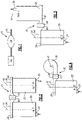
- FIG. 1 shows a vehicle exhaust system 10 that conducts hot exhaust gases generated by an engine 12 through various exhaust components 14 to reduce emission and control noise as known.
- the various exhaust components 14 can include diesel oxidation catalysts (DOC), selective catalytic reduction (SCR) catalysts, particulate filters, mufflers, exhaust pipes, etc. These components 14 can be mounted in various different configurations and combinations dependent upon vehicle application and available packaging space. Engine exhaust gases go through the components 14 and exit to the atmosphere via a tailpipe 16.
- DOC diesel oxidation catalysts
- SCR selective catalytic reduction
- the exhaust components 14 comprise a first exhaust component 20 and a second exhaust component 22 that is downstream of the first exhaust component 20.
- the first exhaust component 20 includes an inlet 24 that receives exhaust gases from the engine 12 or another upstream exhaust component and an outlet 26.
- the second exhaust component 22 includes an inlet 28, which is downstream of the outlet 26 of the first exhaust component 20, and an outlet 30. Additional components 14 could be positioned upstream of the first exhaust component 20 and/or downstream of the second exhaust component 22 as known.
- a mixer 32 connects the outlet 26 of the first exhaust component 20 to the inlet 28 to the second exhaust component 22.
- the mixer 32 includes a first housing portion 34 with a first connection interface 36 and a second housing portion 38 with a second connection interface 40.
- the first housing portion 34 is attached to the outlet 26 of the first exhaust component 20 and the second housing portion 38 is attached to the inlet 28 of the second exhaust component 22.
- the first 36 and second 40 connection interfaces are connectable to each other in one of a plurality of different connection orientations such that the first 20 and second 22 exhaust components can be positioned at any of a plurality of different mounting orientations relative to each other.
- Mounting orientations can vary due to vehicle size and type. For example, larger vehicles may have more available packaging space than smaller vehicles, which makes it more difficult to efficiently package exhaust components in the limited available space.
- a desired mounting orientation is selected from the plurality of different available mounting orientations the first 36 and second 40 connection interfaces are arranged relative to each other to place the first 20 and second 22 exhaust components in the desired mounting orientation. Then, the first 36 and second 40 connection interfaces are fixed to each other by any of various methods such as welding, brazing, fastening, etc., for example.
- the first exhaust component 20 defines a first central axis A1 extending along a length of the first exhaust component 20 and the second exhaust 22 component defines a second central axis A2 extending along a length of the second exhaust component 22.
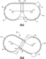
- the selected one of the plurality of different connection orientations is a parallel orientation where the first central axis A1 is parallel to the second central axis A2.
- the first 20 and second 22 exhaust components extend outwardly from the same side of the mixer 32.
- the example shown in Figure 3 is also a parallel configuration; however, the first exhaust component 20 extends outwardly from one side of the mixer 32 and the second exhaust component 22 extends outwardly from an opposite side of the mixer 32. In this configuration one of the exhaust components 20, 22 has been rotated 180 degrees relative to the other exhaust component 20, 22.
- the first central axis A1 is parallel to the second central axis A2.
- the selected connection orientation comprises a perpendicular orientation where the first central axis A1 is perpendicular to the second central axis A2.
- one of the exhaust components 20, 22 has been rotated 90 degrees relative to the other exhaust component 20, 22.
- Figures 5-6 show other examples of parallel configurations where the first A1 and second A2 axes are parallel to each other.
- the exhaust components 20, 22 can be positioned in any of an infinite number of different mounting orientations relative to each other.
- the first exhaust component 20 comprises a diesel particulate filter DPF and the second exhaust component 22 comprises a selective catalytic reduction (SCR) catalyst.
- An injector 42 is mounted to the mixer 32 to introduce a fluid, such as urea for example, to be mixed with exhaust gases by the mixer 32.
- the injector 42 is mounted to the first housing portion 34 of the mixer 32 adjacent the outlet 26 from the DPF; however, the injector 42 could also be mounted at other locations dependent upon system requirements and available packaging space. It should be understood that while the components are shows as being a DPF and SCR catalyst, other combinations of components could be connected to each other via the mixer 32.
- the first 34 and second 38 housing portions each comprise a bottom surface 50 with a wall 52 extending outwardly about an outer periphery 54 of the bottom surface 50.
- the first 34 and second 38 housing portions each comprise a bowl-shaped component defining a mixer center C and having an open end 56 configured for attachment to a respective one of the first 20 and second 22 exhaust components.
- baffles or other structures Inside the mixer 32 are baffles or other structures that are used to mix the exhaust gas with the injected fluid. It should be understood that any type of mixer could be used to connect the exhaust components together, and that the mixer could have any of various different shapes.
- first 36 and second 40 connection interfaces comprise axial extension portions 58 that extend tangentially relative to the wall 52.
- the first 36 and second 40 connection interfaces each comprise axial extension portions 58 that are radially offset from the mixer center C.
- each of the first 36 and second 40 connection interfaces comprises a first tubular extension 60 defined by a first cross-section shape 60a ( Figure 8A ) and a coupling portion 62 defined by a second cross-section shape 62a ( Figure 8B ) that is different than the first cross-section shape 60a.
- the first cross-section shape 60a is polygonal and the second cross-section 62a shape is curvilinear.
- the first cross-section shape 60a is square or rectangular forming a square or rectangular tube portion
- the second cross-section shape 62a is circular forming a circular coupling portion.
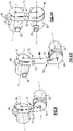
- Figures 9-11 show additional examples of different mounting configurations for the first 20 and second 22 exhaust components. Further, these examples show a different connection interface 70 for each of the housing portions 34, 38.
- the connection interface comprises a neck or narrowed down portion, as indicated at 72, to connect to the corresponding neck 72 of the other housing portion.
- the shapes of the necks can comprise any of various shapes.
- Figure 9 shows a perpendicular configuration where the second housing portion 34 has been rotated 90 degrees relative to the first housing portion 34 such that the first A1 and second A2 central axes are perpendicular and non-intersecting.
- Figure 10 shows a parallel configuration where the axes A1, A2 are spaced apart and parallel to each other.
- Figure 11 shows a configuration similar to Figure 9 but which includes a tubular extension 80 to lengthen the distance between the components 20, 22.
- the subject invention uses a modular mixer design that includes first and second housing portions to provide a plenum connection interface between two exhaust components.
- the use of a connecting joint for each housing portion allows multiple clocking positions. Providing a cross-section change from polygonal to curvilinear makes the design modular and enables the installation in multiple clocking positions.
- the modular configuration could be adapted for various packages without a large change to mixing performance.
Landscapes
- Engineering & Computer Science (AREA)
- Chemical & Material Sciences (AREA)
- Chemical Kinetics & Catalysis (AREA)
- Combustion & Propulsion (AREA)
- Mechanical Engineering (AREA)
- General Engineering & Computer Science (AREA)
- Health & Medical Sciences (AREA)
- Toxicology (AREA)
- Exhaust Gas After Treatment (AREA)
Description
- The subject invention relates to a vehicle exhaust system that includes a modular mixer that can be utilized in various different exhaust system configurations.
- An exhaust system conducts hot exhaust gases generated by an engine through various exhaust components to reduce emissions and control noise. The exhaust system includes components such as filters, diesel oxidation catalysts (DOC), selective catalytic reduction (SCR) catalysts, mufflers, tailpipes, etc. that are coupled together to conduct the engine exhaust gases to an external atmosphere. Often a mixer component is utilized to thoroughly mix exhaust gases with a fluid that is introduced into the exhaust gas flow via an injector. An example of such a fluid would be fuel for a fuel-fired burner or urea for a SCR catalyst.
- These components are arranged in different configurations dependent upon vehicle size and/or vehicle application. It is often difficult to arrange all of the exhaust system components efficiently within tight packaging restraints. Further, each vehicle configuration has a different packaging envelope, which can require slightly different connection orientations between mating components for each different configuration. This can disadvantageously increase cost.
-
EP 2 123 878 A1 discloses a vehicle exhaust component assembly with a particulate filter and a selective reduction catalyst that are connected via an S-shaped communication passage, which forwards the exhaust gas from a rear end of the particulate filter to a front end of the adjacent selective reduction catalyst. The S-shaped communication passage comprises an intermediate pipe, to which pipe an injector is attached. -
US 2013 0 164 182 A1 discloses a reducing agent aqueous solution mixing device comprising an exhaust pipe, an injector, a mixing pipe and an inner pipe. The exhaust pipe includes an elbow part having a curved portion and a linear part, wherein the injector injects the reducing agent into the linear part, and wherein the mixing pipe is disposed inside the elbow part. -
JP 2009 - 167 806 A - In one exemplary embodiment, a vehicle exhaust component assembly includes a first exhaust component, a second exhaust component downstream of the first exhaust component, and a mixer that connects an outlet of the first exhaust component to an inlet to the second exhaust component. The mixer includes a first housing portion with a first connection interface and a second housing portion with a second connection interface. The first housing portion is attached to the outlet of the first exhaust component and the second housing portion is attached to the inlet of the second exhaust component. One of the first and second exhaust components comprises a catalyst and the other of the first and second exhaust components comprises a diesel particulate filter. An injector is mounted to one of the first and second housing portions adjacent an outlet of the diesel particulate filter, wherein the injector is configured to inject a fluid into the mixer. The first and second connection interfaces are connectable to each other in one of a plurality of different connection orientations such that the first and second exhaust components can be positioned at any of a plurality of different mounting orientations relative to each other. The first and second housing portions each comprise a bowl-shaped component defining a mixer center and having an open end configured for attachment to a respective one of the first and second exhaust components, and the first and second housing portions each comprise a bottom surface with a wall extending outwardly about an outer periphery of the bottom surface. The first and second connection interfaces comprise axial extension portions that are radial offset from the respective mixer center and extend tangentially relative to the wall.
- In a further embodiment of the above, one of the first and second connection interfaces is rotated relative to the other of the first and second connection interfaces when moving between the plurality of connection orientations.
- In a further embodiment of any of the above, each of the first and second connection interfaces comprises a first tubular extension defined by a first cross-section shape and a coupling portion defined by a second cross-section shape that is different than the first cross-section shape.
- In a further embodiment of any of the above, the first cross-section shape is polygonal and the second cross-section shape is curvilinear.
- In a further embodiment of any of the above, the first exhaust component defines a first central axis extending along a length of the first exhaust component and the second exhaust component defines a second central axis extending along a length of the second exhaust component, and wherein one of the plurality of different connection orientations comprises a parallel orientation where the first central axis is parallel to the second central axis.
- In a further embodiment of any of the above, another one of the plurality of different connection orientations comprises a perpendicular orientation where the first central axis is perpendicular to the second central axis.
- In another exemplary embodiment, a method of assembling the vehicle exhaust component assembly according to the present invention includes the steps of providing a mixer comprising a first housing portion with a first connection interface and a second housing portion with a second connection interface, wherein the first and second housing portions each comprise a bowl-shaped component defining a mixer center and having an open end configured for attachment to a respective one of the first and second exhaust components, and wherein the first and second housing portions each comprise a bottom surface with a wall extending outwardly about an outer periphery of the bottom surface, and wherein the first and second connection interfaces comprise axial extension portions that are radially offset from the respective mixer center, connecting the first housing portion to an outlet of the first exhaust component, connecting the second housing portion to an inlet of the second exhaust component, selecting a desired mounting orientation from a plurality of mounting orientations of the first and second exhaust components relative to each other, moving one of the first and second connection interfaces relative to the other of the first and second connection interfaces to place the first and second exhaust components in the desired mounting orientation, and fixing the first and second connection interfaces to each other.
- These and other features of this application will be best understood from the following specification and drawings, the following of which is a brief description.
-
-
Figure 1 schematically illustrates one example of an exhaust system. -
Figure 2 is a schematic view of one example of a modular mixer in one mounting configuration. -
Figure 3 is a schematic view of one example of a modular mixer in another mounting configuration. -
Figure 4 is a schematic view of one example of a modular mixer in another mounting configuration. -
Figure 5 is a schematic view of one example of a modular mixer in another mounting configuration. -
Figure 6 is a schematic view of one example of a modular mixer in another mounting configuration. -
Figure 7 is a schematic side view of the mixer fromFigures 2-6 . -
Figure 8 is a top view of the mixer ofFigure 7 . -
Figure 8A is a section view taken along A-A as indicated inFigure 8 . -
Figure 8B is a section view taken along B-B as indicated inFigure 8 . -
Figure 9 is a schematic view of one example of a modular mixer in another mounting configuration. -
Figure 10 is a schematic view of one example of a modular mixer in another mounting configuration. -
Figure 11 is a schematic view of one example of a modular mixer in another mounting configuration. -
Figure 1 shows avehicle exhaust system 10 that conducts hot exhaust gases generated by anengine 12 throughvarious exhaust components 14 to reduce emission and control noise as known. Thevarious exhaust components 14 can include diesel oxidation catalysts (DOC), selective catalytic reduction (SCR) catalysts, particulate filters, mufflers, exhaust pipes, etc. Thesecomponents 14 can be mounted in various different configurations and combinations dependent upon vehicle application and available packaging space. Engine exhaust gases go through thecomponents 14 and exit to the atmosphere via atailpipe 16. - In one example shown in
Figure 2 , theexhaust components 14 comprise afirst exhaust component 20 and asecond exhaust component 22 that is downstream of thefirst exhaust component 20. Thefirst exhaust component 20 includes aninlet 24 that receives exhaust gases from theengine 12 or another upstream exhaust component and anoutlet 26. Thesecond exhaust component 22 includes aninlet 28, which is downstream of theoutlet 26 of thefirst exhaust component 20, and anoutlet 30.Additional components 14 could be positioned upstream of thefirst exhaust component 20 and/or downstream of thesecond exhaust component 22 as known. - A
mixer 32 connects theoutlet 26 of thefirst exhaust component 20 to theinlet 28 to thesecond exhaust component 22. Themixer 32 includes afirst housing portion 34 with afirst connection interface 36 and asecond housing portion 38 with asecond connection interface 40. Thefirst housing portion 34 is attached to theoutlet 26 of thefirst exhaust component 20 and thesecond housing portion 38 is attached to theinlet 28 of thesecond exhaust component 22. The first 36 and second 40 connection interfaces are connectable to each other in one of a plurality of different connection orientations such that the first 20 and second 22 exhaust components can be positioned at any of a plurality of different mounting orientations relative to each other. - Mounting orientations can vary due to vehicle size and type. For example, larger vehicles may have more available packaging space than smaller vehicles, which makes it more difficult to efficiently package exhaust components in the limited available space. Once a desired mounting orientation is selected from the plurality of different available mounting orientations the first 36 and second 40 connection interfaces are arranged relative to each other to place the first 20 and second 22 exhaust components in the desired mounting orientation. Then, the first 36 and second 40 connection interfaces are fixed to each other by any of various methods such as welding, brazing, fastening, etc., for example.
- The
first exhaust component 20 defines a first central axis A1 extending along a length of thefirst exhaust component 20 and thesecond exhaust 22 component defines a second central axis A2 extending along a length of thesecond exhaust component 22. In the example shown inFigure 2 , the selected one of the plurality of different connection orientations is a parallel orientation where the first central axis A1 is parallel to the second central axis A2. Further, the first 20 and second 22 exhaust components extend outwardly from the same side of themixer 32. - The example shown in
Figure 3 is also a parallel configuration; however, thefirst exhaust component 20 extends outwardly from one side of themixer 32 and thesecond exhaust component 22 extends outwardly from an opposite side of themixer 32. In this configuration one of theexhaust components other exhaust component - In the example shown in
Figure 4 , the selected connection orientation comprises a perpendicular orientation where the first central axis A1 is perpendicular to the second central axis A2. In this configuration, one of theexhaust components other exhaust component -
Figures 5-6 show other examples of parallel configurations where the first A1 and second A2 axes are parallel to each other. Thus, by simply rotating the connection interfaces 36, 40 relative to each other, theexhaust components - In these examples, the
first exhaust component 20 comprises a diesel particulate filter DPF and thesecond exhaust component 22 comprises a selective catalytic reduction (SCR) catalyst. Aninjector 42 is mounted to themixer 32 to introduce a fluid, such as urea for example, to be mixed with exhaust gases by themixer 32. In the example shown, theinjector 42 is mounted to thefirst housing portion 34 of themixer 32 adjacent theoutlet 26 from the DPF; however, theinjector 42 could also be mounted at other locations dependent upon system requirements and available packaging space. It should be understood that while the components are shows as being a DPF and SCR catalyst, other combinations of components could be connected to each other via themixer 32. - As shown in
Figures 7-8 , the first 34 and second 38 housing portions each comprise abottom surface 50 with awall 52 extending outwardly about anouter periphery 54 of thebottom surface 50. In this example, the first 34 and second 38 housing portions each comprise a bowl-shaped component defining a mixer center C and having anopen end 56 configured for attachment to a respective one of the first 20 and second 22 exhaust components. Inside themixer 32 are baffles or other structures that are used to mix the exhaust gas with the injected fluid. It should be understood that any type of mixer could be used to connect the exhaust components together, and that the mixer could have any of various different shapes. - In the example shown, the first 36 and second 40 connection interfaces comprise
axial extension portions 58 that extend tangentially relative to thewall 52. As such, the first 36 and second 40 connection interfaces each compriseaxial extension portions 58 that are radially offset from the mixer center C. In one example, each of the first 36 and second 40 connection interfaces comprises a firsttubular extension 60 defined by afirst cross-section shape 60a (Figure 8A ) and acoupling portion 62 defined by asecond cross-section shape 62a (Figure 8B ) that is different than thefirst cross-section shape 60a. In one example, thefirst cross-section shape 60a is polygonal and thesecond cross-section 62a shape is curvilinear. For example, thefirst cross-section shape 60a is square or rectangular forming a square or rectangular tube portion, and thesecond cross-section shape 62a is circular forming a circular coupling portion. By providing a curvilinear coupling for eachhousing portion housing portions coupling portions 62 are fixed together. -
Figures 9-11 show additional examples of different mounting configurations for the first 20 and second 22 exhaust components. Further, these examples show adifferent connection interface 70 for each of thehousing portions neck 72 of the other housing portion. The shapes of the necks can comprise any of various shapes. -
Figure 9 shows a perpendicular configuration where thesecond housing portion 34 has been rotated 90 degrees relative to thefirst housing portion 34 such that the first A1 and second A2 central axes are perpendicular and non-intersecting.Figure 10 shows a parallel configuration where the axes A1, A2 are spaced apart and parallel to each other.Figure 11 shows a configuration similar toFigure 9 but which includes atubular extension 80 to lengthen the distance between thecomponents - The subject invention uses a modular mixer design that includes first and second housing portions to provide a plenum connection interface between two exhaust components. The use of a connecting joint for each housing portion allows multiple clocking positions. Providing a cross-section change from polygonal to curvilinear makes the design modular and enables the installation in multiple clocking positions. Thus, the modular configuration could be adapted for various packages without a large change to mixing performance.
- Although an embodiment of this invention has been disclosed, a worker of ordinary skill in this art would recognize that certain modifications would come within the scope of this invention. For that reason, the following claims should be studied to determine the true scope and content of this invention.
Claims (11)
- A vehicle exhaust component assembly comprising:a first exhaust component (20);a second exhaust component (22) downstream of the first exhaust component (20);a mixer (32) connecting an outlet (26) of the first exhaust component (20) to an inlet (28) to the second exhaust component (22), the mixer (32) comprising a first housing portion (34) with a first connection interface (36; 70) and a second housing portion (38) with a second connection interface (40; 70) , wherein the first housing portion (34) is attached to the outlet (26) of the first exhaust component (20) and the second housing portion (38) is attached to the inlet (28) of the second exhaust component (22), wherein one of the first and second exhaust components (20, 22) comprises a catalyst and the other of the first and second exhaust components (20, 22) comprises a diesel particulate filter; andan injector (42) mounted to one of the first and second housing portions (34, 38) adjacent an outlet of the diesel particulate filter, the injector (42) configured to inject a fluid into the mixer (32);characterized in that the first and second connection interfaces (36, 40; 70) are connectable to each other in one of a plurality of different connection orientations such that the first and second exhaust components (20, 22) can be positioned at any of a plurality of different mounting orientations relative to each other, and the first and second housing portions each comprise a bowl-shaped component defining a mixer center (C) and having an open end (56) configured for attachment to a respective one of the first and second exhaust components (20, 22), and the first and second housing portions (34, 38) each comprise a bottom surface (50) with a wall (52) extending outwardly about an outer periphery (54) of the bottom surface (50), and wherein the first and second connection interfaces (36, 40; 70) comprise axial extension portions (58) that are radially offset from the respective mixer center (C) and extend tangentially relative to the wall (52).
- The vehicle exhaust component assembly according to claim 1, wherein one of the first and second connection interfaces (36, 40; 70) is rotated relative to the other of the first and second connection interfaces (36, 40; 70) when moving between the plurality of connection orientations.
- The vehicle exhaust component assembly according to claim 1 or 2, wherein each of the first and second connection interfaces (36, 40) comprises a first tubular extension (60) defined by a first cross-section shape (60a) and a coupling portion (62) defined by a second cross-section shape (62a) that is different than the first cross-section shape (60a), in particular wherein the first cross-section shape (60a) is polygonal and the second cross-section shape (62a) is curvilinear.
- The vehicle exhaust component assembly according to any of the preceding claims, wherein the first exhaust component (20) defines a first central axis (A1) extending along a length of the first exhaust component (20) and the second exhaust component (22) defines a second central axis (A2) extending along a length of the second exhaust component (22), and wherein one of the plurality of different connection orientations comprises a parallel orientation where the first central axis (A1) is parallel to the second central axis (A2).
- The vehicle exhaust component assembly according to claim 4, wherein another one of the plurality of different connection orientations comprises a perpendicular orientation where the first central axis (A1) is perpendicular to the second central axis (A2).
- The vehicle exhaust component assembly according to any of the preceding claims, wherein the first and second exhaust components (20, 22) extend from the mixer (32) in opposite directions relative to each other, or wherein the first and second exhaust components (20, 22) extend from the mixer (32) in the same direction.
- The vehicle exhaust component assembly according to any of the preceding claims, wherein the axial extension portions (58) comprise one of a square or rectangular tube that transitions into a generally circular coupling portion.
- A method of assembling a vehicle exhaust component assembly according to claim 1 comprising:(a) providing a mixer (32) comprising a first housing portion (34) with a first connection interface (36; 70) and a second housing portion (38) with a second connection interface (40; 70), wherein the first and second housing portions each comprise a bowl-shaped component defining a mixer center (C) and having an open end (56) configured for attachment to a respective one of the first and second exhaust components (20, 22), and wherein the first and second housing portions (34, 38) each comprise a bottom surface (50) with a wall (52) extending outwardly about an outer periphery (54) of the bottom surface (50), and wherein the first and second connection interfaces (36, 40; 70) comprise axial extension portions (58) that are radially offset from the respective mixer center (C);(b) connecting the first housing portion (34) to an outlet (26) of a first exhaust component (20);(c) connecting the second housing portion (38) to an inlet (28) of a second exhaust component (22);(d) selecting a desired mounting orientation from a plurality of mounting orientations of the first and second exhaust components (20, 22) relative to each other;(e) moving one of the first and second connection interfaces (36, 40; 70) relative to the other of the first and second connection interfaces (36, 40; 70) to place the first and second exhaust components (20, 22) in the desired mounting orientation; and(f) fixing the first and second connection interfaces (36, 40; 70) to each other.
- The method according to claim 8 wherein step (e) further includes rotating one of the first and second connection interfaces (36, 40; 70) relative to the other of the first and second connection interfaces (36, 40; 70).
- The method according to claim 9 wherein one of the plurality of mounting orientations comprises a parallel orientation, and wherein step (e) comprises rotation one of the first and second connection interfaces (36, 40; 70) relative to the other of the first and second connection interfaces (36, 40; 70) such that central axes (A1, A2) defined by the first and second exhaust components (20, 22) are parallel to each other.
- The method according to claim 10 including forming each of the first and second connection interfaces (36, 40; 70) to include a polygonal tubular portion that transitions into a curvilinear tubular portion and wherein step (f) further comprises connecting the curvilinear tubular portions to each other.
Applications Claiming Priority (1)
| Application Number | Priority Date | Filing Date | Title |
|---|---|---|---|
| PCT/US2014/010989 WO2015105500A1 (en) | 2014-01-10 | 2014-01-10 | Modular mixer for exhaust assembly |
Publications (4)
| Publication Number | Publication Date |
|---|---|
| EP3092381A1 EP3092381A1 (en) | 2016-11-16 |
| EP3092381A4 EP3092381A4 (en) | 2017-09-13 |
| EP3092381B1 EP3092381B1 (en) | 2019-05-01 |
| EP3092381B2 true EP3092381B2 (en) | 2022-08-17 |
Family
ID=53524212
Family Applications (1)
| Application Number | Title | Priority Date | Filing Date |
|---|---|---|---|
| EP14878138.8A Active EP3092381B2 (en) | 2014-01-10 | 2014-01-10 | Modular mixer for exhaust assembly |
Country Status (5)
| Country | Link |
|---|---|
| US (1) | US10287954B2 (en) |
| EP (1) | EP3092381B2 (en) |
| KR (1) | KR101848802B1 (en) |
| CN (1) | CN105899776B (en) |
| WO (1) | WO2015105500A1 (en) |
Families Citing this family (12)
| Publication number | Priority date | Publication date | Assignee | Title |
|---|---|---|---|---|
| CN105980679B (en) | 2014-02-07 | 2019-04-23 | 佛吉亚排放控制技术美国有限公司 | Mixer assembly for vehicle exhaust system |
| GB2539711B (en) | 2015-06-26 | 2017-08-16 | Proventia Emission Control Oy | Method and apparatus for evenly mixing reactant to exhaust gas flow |
| US9926891B2 (en) * | 2015-11-18 | 2018-03-27 | General Electric Company | System and method of exhaust gas recirculation |
| DE112017007124T5 (en) | 2017-02-24 | 2019-11-28 | Faurecia Emissions Control Technologies, Usa, Llc | INJEKTORSPRÜHSCHUTZ |
| US10337380B2 (en) | 2017-07-07 | 2019-07-02 | Faurecia Emissions Control Technologies, Usa, Llc | Mixer for a vehicle exhaust system |
| CN111315972A (en) * | 2017-11-03 | 2020-06-19 | 佛吉亚排放控制技术美国有限公司 | Flow reversing mixer assembly |
| US10316721B1 (en) | 2018-04-23 | 2019-06-11 | Faurecia Emissions Control Technologies, Usa, Llc | High efficiency mixer for vehicle exhaust system |
| US10287948B1 (en) | 2018-04-23 | 2019-05-14 | Faurecia Emissions Control Technologies, Usa, Llc | High efficiency mixer for vehicle exhaust system |
| US10787946B2 (en) | 2018-09-19 | 2020-09-29 | Faurecia Emissions Control Technologies, Usa, Llc | Heated dosing mixer |
| US11208934B2 (en) | 2019-02-25 | 2021-12-28 | Cummins Emission Solutions Inc. | Systems and methods for mixing exhaust gas and reductant |
| GB2609163B (en) | 2020-05-08 | 2023-08-23 | Cummins Emission Solutions Inc | Configurable aftertreatment systems including a housing |
| JP7350171B2 (en) * | 2020-05-26 | 2023-09-25 | 株式会社三五 | Exhaust purification device |
Family Cites Families (20)
| Publication number | Priority date | Publication date | Assignee | Title |
|---|---|---|---|---|
| US2123878A (en) * | 1932-08-31 | 1938-07-19 | Wesco Machinery Mfg Co | Method for icing containers |
| DE19731865C2 (en) * | 1997-07-24 | 1999-05-06 | Siemens Ag | Exhaust gas purification system for the exhaust gas of a diesel engine |
| JP4308056B2 (en) * | 2004-03-25 | 2009-08-05 | 日産ディーゼル工業株式会社 | Reducing agent container mounting apparatus and mounting method |
| JP4785766B2 (en) * | 2007-02-09 | 2011-10-05 | 日野自動車株式会社 | Exhaust purification device |
| JP4943499B2 (en) * | 2007-03-12 | 2012-05-30 | ボッシュ株式会社 | Exhaust gas purification device for internal combustion engine |
| JP2008267225A (en) | 2007-04-18 | 2008-11-06 | Futaba Industrial Co Ltd | Exhaust emission control device |
| JP4881213B2 (en) | 2007-04-27 | 2012-02-22 | 日野自動車株式会社 | Exhaust purification device |
| JP4785803B2 (en) | 2007-08-02 | 2011-10-05 | 日野自動車株式会社 | Exhaust purification device |
| DE202007012280U1 (en) | 2007-09-01 | 2009-01-08 | Heinrich Gillet Gmbh | Modular system for exhaust systems of motor vehicles |
| JP4605205B2 (en) * | 2007-11-05 | 2011-01-05 | 株式会社デンソー | Exhaust purification device |
| JP5066435B2 (en) * | 2007-12-14 | 2012-11-07 | 東京濾器株式会社 | Exhaust gas purification equipment for diesel engines |
| JP5114219B2 (en) | 2008-01-10 | 2013-01-09 | 東京濾器株式会社 | Exhaust gas purification device for internal combustion engine |
| DE102009024534A1 (en) | 2009-06-10 | 2010-12-16 | J. Eberspächer GmbH & Co. KG | exhaust gas cleaning device |
| WO2011118035A1 (en) * | 2010-03-26 | 2011-09-29 | トヨタ自動車株式会社 | Problem detection apparatus and problem detection method for particulate filter |
| EP3267005B2 (en) | 2010-06-22 | 2023-12-27 | Donaldson Company, Inc. | Exhaust aftertreatment device |
| DE102010045751B4 (en) | 2010-09-17 | 2017-02-16 | Friedrich Boysen Gmbh & Co. Kg | Exhaust system of an internal combustion engine |
| FR2966197B1 (en) | 2010-10-18 | 2014-08-15 | Faurecia Sys Echappement | EXHAUST LINE FOR MOTOR VEHICLE. |
| JP5349575B2 (en) | 2011-12-27 | 2013-11-20 | 株式会社小松製作所 | Reducing agent aqueous solution mixing device and exhaust gas aftertreatment device |
| KR101369651B1 (en) * | 2012-06-29 | 2014-03-04 | 쌍용자동차 주식회사 | blade mixer for mixing urea of automobile |
| CN104066941B (en) * | 2013-01-17 | 2016-01-20 | 株式会社小松制作所 | Reducing agent aqueous solution device and possess its exhaust gas post-treatment device |
-
2014
- 2014-01-10 KR KR1020167019053A patent/KR101848802B1/en active IP Right Grant
- 2014-01-10 EP EP14878138.8A patent/EP3092381B2/en active Active
- 2014-01-10 WO PCT/US2014/010989 patent/WO2015105500A1/en active Application Filing
- 2014-01-10 CN CN201480072892.4A patent/CN105899776B/en active Active
- 2014-01-10 US US15/039,191 patent/US10287954B2/en active Active
Also Published As
| Publication number | Publication date |
|---|---|
| EP3092381A4 (en) | 2017-09-13 |
| KR20160098441A (en) | 2016-08-18 |
| CN105899776B (en) | 2019-07-23 |
| WO2015105500A1 (en) | 2015-07-16 |
| US20170022870A1 (en) | 2017-01-26 |
| EP3092381B1 (en) | 2019-05-01 |
| US10287954B2 (en) | 2019-05-14 |
| KR101848802B1 (en) | 2018-04-16 |
| EP3092381A1 (en) | 2016-11-16 |
| CN105899776A (en) | 2016-08-24 |
Similar Documents
| Publication | Publication Date | Title |
|---|---|---|
| EP3092381B2 (en) | Modular mixer for exhaust assembly | |
| US7533520B2 (en) | Exhaust aftertreatment mixer with stamped muffler flange | |
| US8826649B2 (en) | Assembly for mixing liquid within gas flow | |
| US7941995B2 (en) | Exhaust aftertreatment system with compliantly coupled sections | |
| CN107530655B (en) | Full-rotating mixer | |
| EP3102802B1 (en) | Mixer assembly for a vehicle exhaust system | |
| CN101821486B (en) | Device for post-treatment of exhaust gases of a lean-burning internal combustion engine | |
| US9719397B2 (en) | Mixer with integrated doser cone | |
| CN107407183A (en) | Exhaust gas purifying unit | |
| EP3313558B1 (en) | Method, apparatus and mixing device for evenly mixing reactant to exhaust gas flow | |
| US10138795B2 (en) | Plenum chamber for exhaust system | |
| CN216588774U (en) | Vehicle exhaust system with end cap mixer | |
| US20210301710A1 (en) | Vehicle exhaust system mixer with flexible doser mount | |
| CN111601958B (en) | Mixer and doser cone assembly with eductor for low temperature conditions | |
| US11725563B2 (en) | Mixer, exhaust aftertreatment component, exhaust aftertreatment system and vehicle | |
| WO2020002990A2 (en) | Large engine mixer for exhaust system | |
| WO2019055922A1 (en) | Exhaust aftertreatment apparatus | |
| GB2510888A (en) | A catalytic converter assembly | |
| US11965449B2 (en) | Venturi mixer with clamshell stamping | |
| CN111550300B (en) | Mixer for an exhaust system | |
| CN111980784B (en) | Vehicle tail gas mixing device and working method thereof | |
| US10794252B1 (en) | Direct spray exhaust mixer system | |
| CN210068277U (en) | Automobile-used tail gas mixing arrangement | |
| CN111980784A (en) | Vehicle tail gas mixing device and working method thereof |
Legal Events
| Date | Code | Title | Description |
|---|---|---|---|
| PUAI | Public reference made under article 153(3) epc to a published international application that has entered the european phase |
Free format text: ORIGINAL CODE: 0009012 |
|
| 17P | Request for examination filed |
Effective date: 20160711 |
|
| AK | Designated contracting states |
Kind code of ref document: A1 Designated state(s): AL AT BE BG CH CY CZ DE DK EE ES FI FR GB GR HR HU IE IS IT LI LT LU LV MC MK MT NL NO PL PT RO RS SE SI SK SM TR |
|
| AX | Request for extension of the european patent |
Extension state: BA ME |
|
| DAX | Request for extension of the european patent (deleted) | ||
| A4 | Supplementary search report drawn up and despatched |
Effective date: 20170817 |
|
| RIC1 | Information provided on ipc code assigned before grant |
Ipc: F01N 3/021 20060101ALI20170810BHEP Ipc: F01N 3/28 20060101AFI20170810BHEP Ipc: F01N 13/10 20100101ALI20170810BHEP Ipc: F01N 13/18 20100101ALI20170810BHEP |
|
| STAA | Information on the status of an ep patent application or granted ep patent |
Free format text: STATUS: EXAMINATION IS IN PROGRESS |
|
| 17Q | First examination report despatched |
Effective date: 20180430 |
|
| GRAP | Despatch of communication of intention to grant a patent |
Free format text: ORIGINAL CODE: EPIDOSNIGR1 |
|
| STAA | Information on the status of an ep patent application or granted ep patent |
Free format text: STATUS: GRANT OF PATENT IS INTENDED |
|
| RIC1 | Information provided on ipc code assigned before grant |
Ipc: F01N 3/20 20060101ALI20181022BHEP Ipc: F01N 13/00 20100101ALI20181022BHEP Ipc: F01N 13/18 20100101ALI20181022BHEP Ipc: F01N 3/021 20060101ALI20181022BHEP Ipc: F01N 13/10 20100101ALI20181022BHEP Ipc: F01N 3/28 20060101AFI20181022BHEP |
|
| INTG | Intention to grant announced |
Effective date: 20181122 |
|
| GRAS | Grant fee paid |
Free format text: ORIGINAL CODE: EPIDOSNIGR3 |
|
| GRAA | (expected) grant |
Free format text: ORIGINAL CODE: 0009210 |
|
| STAA | Information on the status of an ep patent application or granted ep patent |
Free format text: STATUS: THE PATENT HAS BEEN GRANTED |
|
| AK | Designated contracting states |
Kind code of ref document: B1 Designated state(s): AL AT BE BG CH CY CZ DE DK EE ES FI FR GB GR HR HU IE IS IT LI LT LU LV MC MK MT NL NO PL PT RO RS SE SI SK SM TR |
|
| REG | Reference to a national code |
Ref country code: GB Ref legal event code: FG4D |
|
| REG | Reference to a national code |
Ref country code: CH Ref legal event code: EP Ref country code: AT Ref legal event code: REF Ref document number: 1127197 Country of ref document: AT Kind code of ref document: T Effective date: 20190515 |
|
| REG | Reference to a national code |
Ref country code: DE Ref legal event code: R096 Ref document number: 602014046015 Country of ref document: DE |
|
| REG | Reference to a national code |
Ref country code: IE Ref legal event code: FG4D |
|
| REG | Reference to a national code |
Ref country code: NL Ref legal event code: MP Effective date: 20190501 |
|
| REG | Reference to a national code |
Ref country code: LT Ref legal event code: MG4D |
|
| PG25 | Lapsed in a contracting state [announced via postgrant information from national office to epo] |
Ref country code: PT Free format text: LAPSE BECAUSE OF FAILURE TO SUBMIT A TRANSLATION OF THE DESCRIPTION OR TO PAY THE FEE WITHIN THE PRESCRIBED TIME-LIMIT Effective date: 20190901 Ref country code: SE Free format text: LAPSE BECAUSE OF FAILURE TO SUBMIT A TRANSLATION OF THE DESCRIPTION OR TO PAY THE FEE WITHIN THE PRESCRIBED TIME-LIMIT Effective date: 20190501 Ref country code: AL Free format text: LAPSE BECAUSE OF FAILURE TO SUBMIT A TRANSLATION OF THE DESCRIPTION OR TO PAY THE FEE WITHIN THE PRESCRIBED TIME-LIMIT Effective date: 20190501 Ref country code: NL Free format text: LAPSE BECAUSE OF FAILURE TO SUBMIT A TRANSLATION OF THE DESCRIPTION OR TO PAY THE FEE WITHIN THE PRESCRIBED TIME-LIMIT Effective date: 20190501 Ref country code: ES Free format text: LAPSE BECAUSE OF FAILURE TO SUBMIT A TRANSLATION OF THE DESCRIPTION OR TO PAY THE FEE WITHIN THE PRESCRIBED TIME-LIMIT Effective date: 20190501 Ref country code: NO Free format text: LAPSE BECAUSE OF FAILURE TO SUBMIT A TRANSLATION OF THE DESCRIPTION OR TO PAY THE FEE WITHIN THE PRESCRIBED TIME-LIMIT Effective date: 20190801 Ref country code: FI Free format text: LAPSE BECAUSE OF FAILURE TO SUBMIT A TRANSLATION OF THE DESCRIPTION OR TO PAY THE FEE WITHIN THE PRESCRIBED TIME-LIMIT Effective date: 20190501 Ref country code: LT Free format text: LAPSE BECAUSE OF FAILURE TO SUBMIT A TRANSLATION OF THE DESCRIPTION OR TO PAY THE FEE WITHIN THE PRESCRIBED TIME-LIMIT Effective date: 20190501 Ref country code: HR Free format text: LAPSE BECAUSE OF FAILURE TO SUBMIT A TRANSLATION OF THE DESCRIPTION OR TO PAY THE FEE WITHIN THE PRESCRIBED TIME-LIMIT Effective date: 20190501 |
|
| PG25 | Lapsed in a contracting state [announced via postgrant information from national office to epo] |
Ref country code: GR Free format text: LAPSE BECAUSE OF FAILURE TO SUBMIT A TRANSLATION OF THE DESCRIPTION OR TO PAY THE FEE WITHIN THE PRESCRIBED TIME-LIMIT Effective date: 20190802 Ref country code: LV Free format text: LAPSE BECAUSE OF FAILURE TO SUBMIT A TRANSLATION OF THE DESCRIPTION OR TO PAY THE FEE WITHIN THE PRESCRIBED TIME-LIMIT Effective date: 20190501 Ref country code: BG Free format text: LAPSE BECAUSE OF FAILURE TO SUBMIT A TRANSLATION OF THE DESCRIPTION OR TO PAY THE FEE WITHIN THE PRESCRIBED TIME-LIMIT Effective date: 20190801 Ref country code: RS Free format text: LAPSE BECAUSE OF FAILURE TO SUBMIT A TRANSLATION OF THE DESCRIPTION OR TO PAY THE FEE WITHIN THE PRESCRIBED TIME-LIMIT Effective date: 20190501 |
|
| REG | Reference to a national code |
Ref country code: AT Ref legal event code: MK05 Ref document number: 1127197 Country of ref document: AT Kind code of ref document: T Effective date: 20190501 |
|
| PG25 | Lapsed in a contracting state [announced via postgrant information from national office to epo] |
Ref country code: IS Free format text: LAPSE BECAUSE OF FAILURE TO SUBMIT A TRANSLATION OF THE DESCRIPTION OR TO PAY THE FEE WITHIN THE PRESCRIBED TIME-LIMIT Effective date: 20190901 |
|
| PG25 | Lapsed in a contracting state [announced via postgrant information from national office to epo] |
Ref country code: DK Free format text: LAPSE BECAUSE OF FAILURE TO SUBMIT A TRANSLATION OF THE DESCRIPTION OR TO PAY THE FEE WITHIN THE PRESCRIBED TIME-LIMIT Effective date: 20190501 Ref country code: AT Free format text: LAPSE BECAUSE OF FAILURE TO SUBMIT A TRANSLATION OF THE DESCRIPTION OR TO PAY THE FEE WITHIN THE PRESCRIBED TIME-LIMIT Effective date: 20190501 Ref country code: EE Free format text: LAPSE BECAUSE OF FAILURE TO SUBMIT A TRANSLATION OF THE DESCRIPTION OR TO PAY THE FEE WITHIN THE PRESCRIBED TIME-LIMIT Effective date: 20190501 Ref country code: CZ Free format text: LAPSE BECAUSE OF FAILURE TO SUBMIT A TRANSLATION OF THE DESCRIPTION OR TO PAY THE FEE WITHIN THE PRESCRIBED TIME-LIMIT Effective date: 20190501 Ref country code: RO Free format text: LAPSE BECAUSE OF FAILURE TO SUBMIT A TRANSLATION OF THE DESCRIPTION OR TO PAY THE FEE WITHIN THE PRESCRIBED TIME-LIMIT Effective date: 20190501 Ref country code: SK Free format text: LAPSE BECAUSE OF FAILURE TO SUBMIT A TRANSLATION OF THE DESCRIPTION OR TO PAY THE FEE WITHIN THE PRESCRIBED TIME-LIMIT Effective date: 20190501 |
|
| REG | Reference to a national code |
Ref country code: DE Ref legal event code: R026 Ref document number: 602014046015 Country of ref document: DE |
|
| PLBI | Opposition filed |
Free format text: ORIGINAL CODE: 0009260 |
|
| PLAX | Notice of opposition and request to file observation + time limit sent |
Free format text: ORIGINAL CODE: EPIDOSNOBS2 |
|
| PG25 | Lapsed in a contracting state [announced via postgrant information from national office to epo] |
Ref country code: SM Free format text: LAPSE BECAUSE OF FAILURE TO SUBMIT A TRANSLATION OF THE DESCRIPTION OR TO PAY THE FEE WITHIN THE PRESCRIBED TIME-LIMIT Effective date: 20190501 Ref country code: IT Free format text: LAPSE BECAUSE OF FAILURE TO SUBMIT A TRANSLATION OF THE DESCRIPTION OR TO PAY THE FEE WITHIN THE PRESCRIBED TIME-LIMIT Effective date: 20190501 |
|
| 26 | Opposition filed |
Opponent name: TENNECO GMBH Effective date: 20200203 |
|
| PG25 | Lapsed in a contracting state [announced via postgrant information from national office to epo] |
Ref country code: TR Free format text: LAPSE BECAUSE OF FAILURE TO SUBMIT A TRANSLATION OF THE DESCRIPTION OR TO PAY THE FEE WITHIN THE PRESCRIBED TIME-LIMIT Effective date: 20190501 |
|
| PG25 | Lapsed in a contracting state [announced via postgrant information from national office to epo] |
Ref country code: PL Free format text: LAPSE BECAUSE OF FAILURE TO SUBMIT A TRANSLATION OF THE DESCRIPTION OR TO PAY THE FEE WITHIN THE PRESCRIBED TIME-LIMIT Effective date: 20190501 |
|
| PG25 | Lapsed in a contracting state [announced via postgrant information from national office to epo] |
Ref country code: SI Free format text: LAPSE BECAUSE OF FAILURE TO SUBMIT A TRANSLATION OF THE DESCRIPTION OR TO PAY THE FEE WITHIN THE PRESCRIBED TIME-LIMIT Effective date: 20190501 |
|
| PLAF | Information modified related to communication of a notice of opposition and request to file observations + time limit |
Free format text: ORIGINAL CODE: EPIDOSCOBS2 |
|
| PLBB | Reply of patent proprietor to notice(s) of opposition received |
Free format text: ORIGINAL CODE: EPIDOSNOBS3 |
|
| PG25 | Lapsed in a contracting state [announced via postgrant information from national office to epo] |
Ref country code: MC Free format text: LAPSE BECAUSE OF FAILURE TO SUBMIT A TRANSLATION OF THE DESCRIPTION OR TO PAY THE FEE WITHIN THE PRESCRIBED TIME-LIMIT Effective date: 20190501 |
|
| REG | Reference to a national code |
Ref country code: CH Ref legal event code: PL |
|
| GBPC | Gb: european patent ceased through non-payment of renewal fee |
Effective date: 20200110 |
|
| REG | Reference to a national code |
Ref country code: BE Ref legal event code: MM Effective date: 20200131 |
|
| PG25 | Lapsed in a contracting state [announced via postgrant information from national office to epo] |
Ref country code: LU Free format text: LAPSE BECAUSE OF NON-PAYMENT OF DUE FEES Effective date: 20200110 Ref country code: GB Free format text: LAPSE BECAUSE OF NON-PAYMENT OF DUE FEES Effective date: 20200110 |
|
| PG25 | Lapsed in a contracting state [announced via postgrant information from national office to epo] |
Ref country code: BE Free format text: LAPSE BECAUSE OF NON-PAYMENT OF DUE FEES Effective date: 20200131 Ref country code: CH Free format text: LAPSE BECAUSE OF NON-PAYMENT OF DUE FEES Effective date: 20200131 Ref country code: LI Free format text: LAPSE BECAUSE OF NON-PAYMENT OF DUE FEES Effective date: 20200131 |
|
| PG25 | Lapsed in a contracting state [announced via postgrant information from national office to epo] |
Ref country code: IE Free format text: LAPSE BECAUSE OF NON-PAYMENT OF DUE FEES Effective date: 20200110 |
|
| PG25 | Lapsed in a contracting state [announced via postgrant information from national office to epo] |
Ref country code: MT Free format text: LAPSE BECAUSE OF FAILURE TO SUBMIT A TRANSLATION OF THE DESCRIPTION OR TO PAY THE FEE WITHIN THE PRESCRIBED TIME-LIMIT Effective date: 20190501 Ref country code: CY Free format text: LAPSE BECAUSE OF FAILURE TO SUBMIT A TRANSLATION OF THE DESCRIPTION OR TO PAY THE FEE WITHIN THE PRESCRIBED TIME-LIMIT Effective date: 20190501 |
|
| PG25 | Lapsed in a contracting state [announced via postgrant information from national office to epo] |
Ref country code: MK Free format text: LAPSE BECAUSE OF FAILURE TO SUBMIT A TRANSLATION OF THE DESCRIPTION OR TO PAY THE FEE WITHIN THE PRESCRIBED TIME-LIMIT Effective date: 20190501 |
|
| PUAH | Patent maintained in amended form |
Free format text: ORIGINAL CODE: 0009272 |
|
| STAA | Information on the status of an ep patent application or granted ep patent |
Free format text: STATUS: PATENT MAINTAINED AS AMENDED |
|
| 27A | Patent maintained in amended form |
Effective date: 20220817 |
|
| AK | Designated contracting states |
Kind code of ref document: B2 Designated state(s): AL AT BE BG CH CY CZ DE DK EE ES FI FR GB GR HR HU IE IS IT LI LT LU LV MC MK MT NL NO PL PT RO RS SE SI SK SM TR |
|
| REG | Reference to a national code |
Ref country code: DE Ref legal event code: R102 Ref document number: 602014046015 Country of ref document: DE |
|
| PGFP | Annual fee paid to national office [announced via postgrant information from national office to epo] |
Ref country code: DE Payment date: 20221220 Year of fee payment: 10 |
|
| REG | Reference to a national code |
Ref country code: DE Ref legal event code: R082 Ref document number: 602014046015 Country of ref document: DE Representative=s name: HOFFMANN - EITLE PATENT- UND RECHTSANWAELTE PA, DE Ref country code: DE Ref legal event code: R082 Ref document number: 602014046015 Country of ref document: DE |
|
| REG | Reference to a national code |
Ref country code: DE Ref legal event code: R082 Ref document number: 602014046015 Country of ref document: DE Representative=s name: HOFFMANN - EITLE PATENT- UND RECHTSANWAELTE PA, DE |
|
| PGFP | Annual fee paid to national office [announced via postgrant information from national office to epo] |
Ref country code: FR Payment date: 20231211 Year of fee payment: 11 |
|
| PGFP | Annual fee paid to national office [announced via postgrant information from national office to epo] |
Ref country code: DE Payment date: 20240129 Year of fee payment: 11 |