EP3091765A1 - Apparatuses and methods for proximity-based service (prose) user equipment (ue)-to-network relay - Google Patents
Apparatuses and methods for proximity-based service (prose) user equipment (ue)-to-network relay Download PDFInfo
- Publication number
- EP3091765A1 EP3091765A1 EP15195888.1A EP15195888A EP3091765A1 EP 3091765 A1 EP3091765 A1 EP 3091765A1 EP 15195888 A EP15195888 A EP 15195888A EP 3091765 A1 EP3091765 A1 EP 3091765A1
- Authority
- EP
- European Patent Office
- Prior art keywords
- relay
- remote
- receiving
- network
- wireless transceiver
- Prior art date
- Legal status (The legal status is an assumption and is not a legal conclusion. Google has not performed a legal analysis and makes no representation as to the accuracy of the status listed.)
- Granted
Links
- 238000000034 method Methods 0.000 title claims description 23
- 238000010295 mobile communication Methods 0.000 claims abstract description 70
- 238000004891 communication Methods 0.000 claims abstract description 32
- 230000004044 response Effects 0.000 claims abstract description 27
- 230000005540 biological transmission Effects 0.000 claims abstract description 14
- 238000013468 resource allocation Methods 0.000 claims abstract description 6
- 238000005516 engineering process Methods 0.000 description 18
- 238000012545 processing Methods 0.000 description 9
- 238000010586 diagram Methods 0.000 description 4
- 238000006243 chemical reaction Methods 0.000 description 3
- 230000006870 function Effects 0.000 description 3
- 238000007726 management method Methods 0.000 description 2
- 230000004075 alteration Effects 0.000 description 1
- 230000003993 interaction Effects 0.000 description 1
- 239000004973 liquid crystal related substance Substances 0.000 description 1
- 230000007774 longterm Effects 0.000 description 1
- 238000012986 modification Methods 0.000 description 1
- 230000004048 modification Effects 0.000 description 1
- 230000006855 networking Effects 0.000 description 1
- 230000003287 optical effect Effects 0.000 description 1
- 238000012552 review Methods 0.000 description 1
Images


Classifications
-
- H—ELECTRICITY
- H04—ELECTRIC COMMUNICATION TECHNIQUE
- H04W—WIRELESS COMMUNICATION NETWORKS
- H04W8/00—Network data management
- H04W8/005—Discovery of network devices, e.g. terminals
-
- H—ELECTRICITY
- H04—ELECTRIC COMMUNICATION TECHNIQUE
- H04W—WIRELESS COMMUNICATION NETWORKS
- H04W72/00—Local resource management
- H04W72/20—Control channels or signalling for resource management
-
- H—ELECTRICITY
- H04—ELECTRIC COMMUNICATION TECHNIQUE
- H04B—TRANSMISSION
- H04B7/00—Radio transmission systems, i.e. using radiation field
- H04B7/14—Relay systems
- H04B7/15—Active relay systems
- H04B7/155—Ground-based stations
- H04B7/15507—Relay station based processing for cell extension or control of coverage area
-
- H—ELECTRICITY
- H04—ELECTRIC COMMUNICATION TECHNIQUE
- H04W—WIRELESS COMMUNICATION NETWORKS
- H04W4/00—Services specially adapted for wireless communication networks; Facilities therefor
- H04W4/70—Services for machine-to-machine communication [M2M] or machine type communication [MTC]
-
- H—ELECTRICITY
- H04—ELECTRIC COMMUNICATION TECHNIQUE
- H04W—WIRELESS COMMUNICATION NETWORKS
- H04W56/00—Synchronisation arrangements
- H04W56/001—Synchronization between nodes
-
- H—ELECTRICITY
- H04—ELECTRIC COMMUNICATION TECHNIQUE
- H04W—WIRELESS COMMUNICATION NETWORKS
- H04W56/00—Synchronisation arrangements
- H04W56/0055—Synchronisation arrangements determining timing error of reception due to propagation delay
- H04W56/0095—Synchronisation arrangements determining timing error of reception due to propagation delay estimated based on signal strength
-
- H—ELECTRICITY
- H04—ELECTRIC COMMUNICATION TECHNIQUE
- H04W—WIRELESS COMMUNICATION NETWORKS
- H04W76/00—Connection management
- H04W76/10—Connection setup
- H04W76/14—Direct-mode setup
-
- H—ELECTRICITY
- H04—ELECTRIC COMMUNICATION TECHNIQUE
- H04W—WIRELESS COMMUNICATION NETWORKS
- H04W88/00—Devices specially adapted for wireless communication networks, e.g. terminals, base stations or access point devices
- H04W88/02—Terminal devices
- H04W88/04—Terminal devices adapted for relaying to or from another terminal or user
-
- H—ELECTRICITY
- H04—ELECTRIC COMMUNICATION TECHNIQUE
- H04B—TRANSMISSION
- H04B7/00—Radio transmission systems, i.e. using radiation field
- H04B7/14—Relay systems
- H04B7/15—Active relay systems
-
- H—ELECTRICITY
- H04—ELECTRIC COMMUNICATION TECHNIQUE
- H04W—WIRELESS COMMUNICATION NETWORKS
- H04W48/00—Access restriction; Network selection; Access point selection
- H04W48/08—Access restriction or access information delivery, e.g. discovery data delivery
- H04W48/12—Access restriction or access information delivery, e.g. discovery data delivery using downlink control channel
-
- H—ELECTRICITY
- H04—ELECTRIC COMMUNICATION TECHNIQUE
- H04W—WIRELESS COMMUNICATION NETWORKS
- H04W84/00—Network topologies
- H04W84/02—Hierarchically pre-organised networks, e.g. paging networks, cellular networks, WLAN [Wireless Local Area Network] or WLL [Wireless Local Loop]
- H04W84/04—Large scale networks; Deep hierarchical networks
- H04W84/042—Public Land Mobile systems, e.g. cellular systems
- H04W84/047—Public Land Mobile systems, e.g. cellular systems using dedicated repeater stations
-
- Y—GENERAL TAGGING OF NEW TECHNOLOGICAL DEVELOPMENTS; GENERAL TAGGING OF CROSS-SECTIONAL TECHNOLOGIES SPANNING OVER SEVERAL SECTIONS OF THE IPC; TECHNICAL SUBJECTS COVERED BY FORMER USPC CROSS-REFERENCE ART COLLECTIONS [XRACs] AND DIGESTS
- Y02—TECHNOLOGIES OR APPLICATIONS FOR MITIGATION OR ADAPTATION AGAINST CLIMATE CHANGE
- Y02D—CLIMATE CHANGE MITIGATION TECHNOLOGIES IN INFORMATION AND COMMUNICATION TECHNOLOGIES [ICT], I.E. INFORMATION AND COMMUNICATION TECHNOLOGIES AIMING AT THE REDUCTION OF THEIR OWN ENERGY USE
- Y02D30/00—Reducing energy consumption in communication networks
- Y02D30/70—Reducing energy consumption in communication networks in wireless communication networks
Definitions
- the application generally relates to wireless communications, and more particularly, to relay in Proximity-based Service (ProSe) communication.
- ProSe Proximity-based Service
- GSM Global System for Mobile communications
- GPRS General Packet Radio Service
- EDGE Enhanced Data rates for Global Evolution
- WCDMA Wideband Code Division Multiple Access
- CDMA-2000 Code Division Multiple Access 2000
- TD-SCDMA Time Division-Synchronous Code Division Multiple Access
- WiMAX Worldwide Interoperability for Microwave Access
- LTE Long Term Evolution
- LTE-A LTE-Advanced
- TD-LTE Time- Division LTE
- a mobile communication device which may be referred to as User Equipment (UE)
- UE User Equipment
- ProSe Proximity-based Service
- the ProSe represents an enormous recent social-technological trend.
- the ProSe is first introduced in Release 12 of the 3rd Generation Partnership Project (3GPP) specifications.
- 3GPP 3rd Generation Partnership Project
- a ProSe-enabled UE may discover other ProSe-enabled UEs in its vicinity by using only the capabilities of the two UEs or by the assistance of an LTE network.
- a ProSe-enabled UE may act as a relay between two other ProSe-enabled UEs in its proximity or between a ProSe-enabled UE in its proximity and the LTE network, to provide ProSe communication therebetween.
- a ProSe-enabled UE which acts as a relay (referred to as a relay UE herein) is first required to connect to an LTE network and request for radio resources for use in ProSe communication, and is also required to always transmit a Device-to-Device (D2D) Synchronization Signal (D2DSS) for allowing another ProSe-enabled UE which is out of service of the LTE network (referred to as a remote UE) to be able to transmit data to the LTE network via the relay UE.
- D2D Device-to-Device
- D2DSS Device-to-Device
- relay UEs may suffer from serious power consumption due to D2DSS transmission.
- the resource utilization of LTE networks may be inefficient since there may be situations where the requested radio resources have been allocated, but there are no remote UE requests to use ProSe communication.
- a mobile communication device located within a radio signal coverage of a service network to serve as a relay User Equipment (UE) for Proximity-based Service (ProSe) UE-to-network relay.
- the mobile communication device comprises a wireless transceiver and a controller.
- the wireless transceiver is configured to perform wireless transmission and reception to and from the service network and a remote UE which is located out of the radio signal coverage of the service network.
- the controller is configured to transmit a Device-to-Device (D2D) Synchronization Signal (D2DSS) to the remote UE via the wireless transceiver in response to receiving a relay discovery message from the remote UE via the wireless transceiver, and request radio resource allocation from the service network for the remote UE via the wireless transceiver in response to receiving a Direct Communication Request message from the remote UE via the wireless transceiver.
- D2D Device-to-Device
- D2DSS Device-to-Device Synchronization Signal
- a method for ProSe UE-to-network relay executed by a relay UE located within a radio signal coverage of a service network.
- the method comprises the steps of: transmitting a D2DSS to a remote UE which is located out of the radio signal coverage of the service network, in response to receiving a relay discovery message from the remote UE; and requesting radio resource allocation from the service network for the remote UE in response to receiving a Direct Communication Request message from the remote UE.
- a mobile communication device located out of a radio signal coverage of a service network to serve as a remote UE for ProSe UE-to-network relay.
- the mobile communication device comprises a wireless transceiver and a controller.
- the wireless transceiver is configured to perform wireless transmission and reception to and from one or more relay UEs which are located within the radio signal coverage of the service network.
- the controller is configured to receive one or more D2DSSs from the one or more relay UEs via the wireless transceiver in response to transmitting a relay discovery message to the one or more relay UEs via the wireless transceiver, select one of the relay UEs according to the DSDSSs, and transmit a Direct Communication Request message to the selected relay UE via the wireless transceiver to establish a connection with the selected relay UE for ProSe UE-to-network relay.
- a method for ProSe UE-to-network relay executed by a remote UE located out of a radio signal coverage of a service network.
- the method comprises the steps of: receiving one or more D2DSSs from the one or more relay UEs which are located within the radio signal coverage of the service network, in response to transmitting a relay discovery message to the one or more relay UEs; selecting one of the relay UEs according to the DSDSSs; and transmitting a Direct Communication Request message to the selected relay UE to establish a connection with the selected relay UE for ProSe UE-to-network relay.
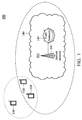
- Fig. 1 is a block diagram of a wireless communication environment according to an embodiment of the application.
- the wireless communication environment 100 comprises three mobile communication devices 110 ⁇ 130 and a service network 140, wherein the mobile communication devices 110 and 120 are located within the radio signal coverage of the service network 140 (denoted with a dashed ellipse in Fig. 1 ) and wirelessly connected to the service network 140 for obtaining mobile services, including the Proximity-based Service (ProSe).
- ProSe Proximity-based Service
- the mobile communication device 130 is located out of the radio signal coverage of the service network 140 but within the range of wireless communications with the mobile communication devices 110 and 120 (denoted with a dotted circle in Fig. 1 ) (or may be referred to as being in proximity to the mobile communication devices 110 and 120).
- All of the mobile communication devices 110 ⁇ 130 are ProSe-enabled UEs, in which the mobile communication devices 110 and 120 are referred to as relay UEs (as they are at in-service area of the service network 140) while the mobile communication device 130 is referred to as a remote UE (as it is at out-of-service area of the service network 140).
- the mobile communication devices 110 and 120 may each serve as a relay to provide ProSe communication between the mobile communication device 130 and the service network 140.
- Each of the mobile communication devices 110 ⁇ 130 may be a feature phone, a smartphone, a panel Personal Computer (PC), a laptop computer, or any computing device supporting the wireless technology utilized by the service network 140.
- the service network 140 is a ProSe-enabled network, such as an LTE network, LTE-A network, or TD-LTE network.
- the service network 140 comprises an access network 141 and a core network 142, wherein the access network 141 is responsible for processing radio signals, terminating radio protocols, and connecting the mobile communication devices 110 and 120 with the core network 142, while the core network 142 is responsible for performing mobility management, network-side authentication, and interfaces with public/external networks (e.g., the Internet).
- Each of the access network 141 and the core network 142 may comprise one or more network nodes for carrying out said functions.
- the access network 141 may be an Evolved-UTRAN (E-UTRAN) which includes at least an evolved NB (eNB) (e.g., a home eNB, macro BS, or pico BS), and the core network 142 may be an Evolved Packet Core (EPC) which includes a Home Subscriber Server (HSS), Mobility Management Entity (MME), Serving Gateway (S-GW), Packet Data Network Gateway (PDN-GW or P-GW), Secure User Plane Location (SUPL) Location Platform (SLP), and ProSe function node, etc.
- E-UTRAN Evolved-UTRAN
- eNB evolved NB
- EPC Evolved Packet Core
- HSS Home Subscriber Server
- MME Mobility Management Entity
- S-GW Serving Gateway
- PDN-GW Packet Data Network Gateway
- SLP Secure User Plane Location
- ProSe function node etc.
- the core network 142 may also be connected to a public safety Access Stratum (AS) which provides services regarding public safety.
- AS public safety Access Stratum
- the public safety AS may serve as a control center or report collecting center for emergencies, such as large scale natural disasters, power cuts, etc.
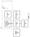
- Fig. 2 is a block diagram illustrating a mobile communication device according to an embodiment of the application.
- the mobile communication device may be any one of the mobile communication devices 110 ⁇ 130. It comprises a wireless transceiver 10, a controller 20, a storage device 30, a display device 40, and an input device 50.
- the wireless transceiver 10 is configured to perform wireless transmission and reception to and from the service network 140 and other nearby mobile communication devices.
- the wireless transceiver 10 comprises a Radio Frequency (RF) device 11, a baseband processing device 12, and an antenna 13.
- the baseband processing device 12 is configured to perform baseband signal processing and control the communications between subscriber identity card(s) (not shown) and the RF device 11.
- the baseband processing device 12 may contain multiple hardware components to perform the baseband signal processing, including Analog-to-Digital Conversion (ADC)/Digital-to-Analog Conversion (DAC), gain adjusting, modulation/demodulation, encoding/decoding, and so on.
- the RF device 11 may receive RF wireless signals via the antenna 13, convert the received RF wireless signals to baseband signals, which are processed by the baseband processing device 12, or receive baseband signals from the baseband processing device 12 and convert the received baseband signals to RF wireless signals, which are later transmitted via the antenna 13.
- the RF device 11 may also contain multiple hardware devices to perform radio frequency conversion.
- the RF device 10 may comprise a mixer to multiply the baseband signals with a carrier oscillated in the radio frequency of the supported wireless technology, wherein the radio frequency may be 900MHz, 2100MHz, or 2.6GHz utilized in LTE/LTE-A/TD-LTE technology, or another radio frequency, such as an unlicensed frequency band (e.g., 2.4GHz) or a licensed frequency band for another wireless technology.
- the radio frequency may be 900MHz, 2100MHz, or 2.6GHz utilized in LTE/LTE-A/TD-LTE technology, or another radio frequency, such as an unlicensed frequency band (e.g., 2.4GHz) or a licensed frequency band for another wireless technology.
- the controller 20 may be a general-purpose processor, a Micro Control Unit (MCU), an application processor, a Digital Signal Processor (DSP), or the like, for controlling the wireless transceiver 10 for wireless communications with the service network 140 and other nearby mobile communication devices, storing and retrieving data to and from the storage device 30, sending a series of frame data (e.g. representing text messages, graphics, images, etc.) to the display device 40, receiving signals from the input device 50.
- the controller 20 coordinates the aforementioned operations of the wireless transceiver 10, the storage device 30, the display device 40, and the input device 50 for performing the method for ProSe UE-to-network relay.
- controller 20 may be incorporated into the baseband processing device 12, serving as a baseband processor.
- the storage device 30 may be a memory, such as a FLASH memory or a Non-volatile Random Access Memory (NVRAM), or a magnetic storage device, such as a hard disk or a magnetic tape, or an optical disc, or any combination thereof for storing instructions and/or program code of applications and/or communication protocols.
- NVRAM Non-volatile Random Access Memory
- the display device 40 may be a Liquid-Crystal Display (LCD), Light-Emitting Diode (LED) display, or Electronic Paper Display (EPD), etc., for providing a display function.
- the display device 40 may further comprise one or more touch sensors disposed thereon or thereunder for sensing touches, contacts, or approximations of objects, such as fingers or styluses.
- the input device 50 may comprise one or more buttons, a keyboard, a mouse, a touch pad, a video camera, a microphone, and/or a speaker, etc., serving as the Man-Machine Interface (MMI) for interaction with users.
- MMI Man-Machine Interface
- Fig. 2 are for illustrative purposes only and are not intended to limit the scope of the application.
- Fig. 3 is a message sequence chart illustrating the ProSe UE-to-network relay according to an embodiment of application.
- both the mobile communication devices 110 and 120 perform a connection establishment procedure with the service network 140 without requesting any radio resource for ProSe UE-to-network relay and transmitting a D2DSS (step S310).
- both the mobile communication devices 110 and 120 indicate, through the connection establishment procedure, to the service network 140 of that they are relays for ProSe UE-to-network relay.
- the connection establishment procedure may include an attach procedure and/or setup of a Packet Data Network (PDN) connectivity.
- PDN Packet Data Network
- the mobile communication device 130 performs a relay discovery procedure to look for relay UEs in its proximity (step S320). Specifically, the mobile communication device 130 broadcasts a relay discovery message, and both the mobile communication devices 110 and 120 start transmitting a D2DSS for a predetermined period of time in response to receiving the relay discovery message. For example, each of the mobile communication devices 110 and 120 may start a guard timer to count the predetermined period of time, and stop the transmission of the D2DSS if no Direct Communication Request message is received from the mobile communication device 130 before the guard timer expires.
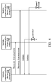
- the relay discovery procedure may be a Model A discovery as shown in Fig. 4 , wherein the relay discovery message is a Discovery Announcement message and the mobile communication devices 110 and 120 do not need to reply to the mobile communication device 130 when receiving the Discovery Announcement message.
- the mobile communication devices 110 and 120 just start the D2DSS transmission with the guard timer in response to receiving the Discovery Announcement message.
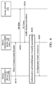
- the relay discovery procedure may be a Model B discovery as shown in Fig. 5 , wherein the relay discovery message is a Discovery Solicitation message and each of the mobile communication devices 110 and 120 replies to the mobile communication device 130 with a Discovery Response message when receiving the Discovery Solicitation message.
- the relay discovery message is a Discovery Solicitation message
- each of the mobile communication devices 110 and 120 replies to the mobile communication device 130 with a Discovery Response message when receiving the Discovery Solicitation message.
- the mobile communication devices 110 and 120 may alternatively choose to start the D2DSS transmissions with the guard timers after transmitting the Discovery Response message.
- each of the mobile communication devices 110 and 120 may determine whether it wants to be a relay for the mobile communication device 130 when receiving the Discovery Solicitation message, and only transmit the D2DSS and the Discovery Response message if it wants to be a relay.
- the mobile communication device 130 subsequently measures the received signal strengths or qualities of the received D2DSSs and then selects one of the mobile communication devices 110 and 120 with the best received signal strength or quality (step S330).
- the received signal strength or quality of a D2DSS may refer to the Received Signal Strength Indication (RSSI), Signal-to-Noise Ratio (SNR), Adjacent Channel Interference (ACI), Packet Error Rate (PER), or Bit Error Rate (BER) of the D2DSS.
- RSSI Received Signal Strength Indication
- SNR Signal-to-Noise Ratio
- ACI Adjacent Channel Interference
- PER Packet Error Rate
- BER Bit Error Rate
- the mobile communication device 130 performs establishment of connection for one-to-one communication with the selected mobile communication device (step S340).
- the mobile communication device 110 is the one with the best received signal strength or quality of D2DSS, and is selected in step S330.
- the mobile communication device 110 serves as a relay to forward unicast traffic between the mobile communication device 130 and the service network 140.
- Fig. 6 is a message sequence chart illustrating the establishment of connection for one-to-one communication according to the embodiment of Fig. 3 .
- the mobile communication device 130 transmits a Direct Communication Request message to the mobile communication device 110 (step S610).
- the mobile communication device 110 requests radio resource allocation from the service network 140 for the mobile communication device 130.
- the mobile communication device 110 transmits a Scheduling Request (SR) message or a Buffer Status Report (BSR) message to the access network 141 (step S620), and receives an Uplink (UL) Grant message including configurations of allocated radio resources from the access network 141 (step S630).
- SR Scheduling Request
- BSR Buffer Status Report
- UL Uplink
- the mobile communication device 110 performs authentication and establishment of security association with the mobile communication device 130 (step S640).
- the mobile communication device 110 first initiates mutual authentication with the mobile communication device 130 and then indicates the establishment of the secure layer-2 link over PC5 (which is an interface between UEs, specified in 3GPP TR23.703, sec. 4.3.2).
- the mobile communication device 110 may optionally transmit a message including the configuration of the allocated radio resource in step S630 to the mobile communication device 130 (step S650).
- step S650 may be omitted.
- the message in step S650 may be a Radio Resource Control (RRC) Reconfiguration Request message.
- RRC Radio Resource Control
- the present application realizes improved ProSe UE-to-network relay by allowing the relay UEs to transmit the D2DSS only in a limited period of time and to request for network resources only when receiving a Direct Communication Request message from a remote UE.
- this greatly reduces the power consumption of relay UEs due to D2DSS transmission and improves the resource utilization of LTE networks.
Abstract
Description
- This Application claims priority of
U.S. Provisional Application No. 62/158,629, filed on May 08, 2015 U.S. Application No. 14/918,717, filed on October 21, 2015 - The application generally relates to wireless communications, and more particularly, to relay in Proximity-based Service (ProSe) communication.
- With growing demand for ubiquitous computing and networking, various wireless technologies have been developed, including Global System for Mobile communications (GSM) technology, General Packet Radio Service (GPRS) technology, Enhanced Data rates for Global Evolution (EDGE) technology, Wideband Code Division Multiple Access (WCDMA) technology, Code Division Multiple Access 2000 (CDMA-2000) technology, Time Division-Synchronous Code Division Multiple Access (TD-SCDMA) technology, Worldwide Interoperability for Microwave Access (WiMAX) technology, Long Term Evolution (LTE) technology, LTE-Advanced (LTE-A) technology, and Time- Division LTE (TD-LTE) technology, etc. By employing one of the wireless technologies, a mobile communication device (which may be referred to as User Equipment (UE)) may wirelessly connect to a service network for accessing the Internet or obtaining mobile services, including the Proximity-based Service (ProSe), anytime and anywhere. The ProSe represents an enormous recent social-technological trend.
- Using LTE technology as an example, the ProSe is first introduced in
Release 12 of the 3rd Generation Partnership Project (3GPP) specifications. A ProSe-enabled UE may discover other ProSe-enabled UEs in its vicinity by using only the capabilities of the two UEs or by the assistance of an LTE network. In addition to ProSe discovery, a ProSe-enabled UE may act as a relay between two other ProSe-enabled UEs in its proximity or between a ProSe-enabled UE in its proximity and the LTE network, to provide ProSe communication therebetween. However, according to the 3GPP Technical Report (TR) 23.713, a ProSe-enabled UE which acts as a relay (referred to as a relay UE herein) is first required to connect to an LTE network and request for radio resources for use in ProSe communication, and is also required to always transmit a Device-to-Device (D2D) Synchronization Signal (D2DSS) for allowing another ProSe-enabled UE which is out of service of the LTE network (referred to as a remote UE) to be able to transmit data to the LTE network via the relay UE. As a result, relay UEs may suffer from serious power consumption due to D2DSS transmission. Moreover, the resource utilization of LTE networks may be inefficient since there may be situations where the requested radio resources have been allocated, but there are no remote UE requests to use ProSe communication. - In a first aspect of the application, a mobile communication device located within a radio signal coverage of a service network to serve as a relay User Equipment (UE) for Proximity-based Service (ProSe) UE-to-network relay is provided. The mobile communication device comprises a wireless transceiver and a controller. The wireless transceiver is configured to perform wireless transmission and reception to and from the service network and a remote UE which is located out of the radio signal coverage of the service network. The controller is configured to transmit a Device-to-Device (D2D) Synchronization Signal (D2DSS) to the remote UE via the wireless transceiver in response to receiving a relay discovery message from the remote UE via the wireless transceiver, and request radio resource allocation from the service network for the remote UE via the wireless transceiver in response to receiving a Direct Communication Request message from the remote UE via the wireless transceiver.
- In a second aspect of the application, a method for ProSe UE-to-network relay, executed by a relay UE located within a radio signal coverage of a service network, is provided. The method comprises the steps of: transmitting a D2DSS to a remote UE which is located out of the radio signal coverage of the service network, in response to receiving a relay discovery message from the remote UE; and requesting radio resource allocation from the service network for the remote UE in response to receiving a Direct Communication Request message from the remote UE.
- In a third aspect of the application, a mobile communication device, located out of a radio signal coverage of a service network to serve as a remote UE for ProSe UE-to-network relay is provided. The mobile communication device comprises a wireless transceiver and a controller. The wireless transceiver is configured to perform wireless transmission and reception to and from one or more relay UEs which are located within the radio signal coverage of the service network. The controller is configured to receive one or more D2DSSs from the one or more relay UEs via the wireless transceiver in response to transmitting a relay discovery message to the one or more relay UEs via the wireless transceiver, select one of the relay UEs according to the DSDSSs, and transmit a Direct Communication Request message to the selected relay UE via the wireless transceiver to establish a connection with the selected relay UE for ProSe UE-to-network relay.
- In a fourth aspect of the application, a method for ProSe UE-to-network relay, executed by a remote UE located out of a radio signal coverage of a service network is provided. The method comprises the steps of: receiving one or more D2DSSs from the one or more relay UEs which are located within the radio signal coverage of the service network, in response to transmitting a relay discovery message to the one or more relay UEs; selecting one of the relay UEs according to the DSDSSs; and transmitting a Direct Communication Request message to the selected relay UE to establish a connection with the selected relay UE for ProSe UE-to-network relay.
- Other aspects and features of the invention will become apparent to those with ordinary skill in the art upon review of the following descriptions of specific embodiments of the mobile communication devices and methods for ProSe UE-to-network relay.
- The application can be more fully understood by reading the subsequent detailed description and examples with references made to the accompanying drawings, wherein:
-
Fig. 1 is a block diagram of a wireless communication environment according to an embodiment of the application; -
Fig. 2 is a block diagram illustrating a mobile communication device according to an embodiment of the application; -
Fig. 3 is a message sequence chart illustrating the ProSe UE-to-network relay according to an embodiment of the application; -
Fig. 4 is a message sequence chart illustrating Model A discovery according to the embodiment ofFig. 3 ; -
Fig. 5 is a message sequence chart illustrating Model B discovery according to the embodiment ofFig. 3 ; and -
Fig. 6 is a message sequence chart illustrating the establishment of connection for one-to-one communication according to the embodiment ofFig. 3 . - The following description is made for the purpose of illustrating the general principles of the application and should not be taken in a limiting sense. It should be understood that the embodiments may be realized in software, hardware, firmware, or any combination thereof. The 3GPP specifications are used to teach the spirit of the application, and the application is not limited thereto.
-
Fig. 1 is a block diagram of a wireless communication environment according to an embodiment of the application. Thewireless communication environment 100 comprises threemobile communication devices 110∼130 and aservice network 140, wherein themobile communication devices Fig. 1 ) and wirelessly connected to theservice network 140 for obtaining mobile services, including the Proximity-based Service (ProSe). Themobile communication device 130 is located out of the radio signal coverage of theservice network 140 but within the range of wireless communications with themobile communication devices 110 and 120 (denoted with a dotted circle inFig. 1 ) (or may be referred to as being in proximity to themobile communication devices 110 and 120). All of themobile communication devices 110∼130 are ProSe-enabled UEs, in which themobile communication devices mobile communication device 130 is referred to as a remote UE (as it is at out-of-service area of the service network 140). In addition, themobile communication devices mobile communication device 130 and theservice network 140. Each of themobile communication devices 110∼130 may be a feature phone, a smartphone, a panel Personal Computer (PC), a laptop computer, or any computing device supporting the wireless technology utilized by theservice network 140. - The
service network 140 is a ProSe-enabled network, such as an LTE network, LTE-A network, or TD-LTE network. Specifically, theservice network 140 comprises anaccess network 141 and acore network 142, wherein theaccess network 141 is responsible for processing radio signals, terminating radio protocols, and connecting themobile communication devices core network 142, while thecore network 142 is responsible for performing mobility management, network-side authentication, and interfaces with public/external networks (e.g., the Internet). Each of theaccess network 141 and thecore network 142 may comprise one or more network nodes for carrying out said functions. For example, theaccess network 141 may be an Evolved-UTRAN (E-UTRAN) which includes at least an evolved NB (eNB) (e.g., a home eNB, macro BS, or pico BS), and thecore network 142 may be an Evolved Packet Core (EPC) which includes a Home Subscriber Server (HSS), Mobility Management Entity (MME), Serving Gateway (S-GW), Packet Data Network Gateway (PDN-GW or P-GW), Secure User Plane Location (SUPL) Location Platform (SLP), and ProSe function node, etc. - Although not shown, the
core network 142 may also be connected to a public safety Access Stratum (AS) which provides services regarding public safety. For example, the public safety AS may serve as a control center or report collecting center for emergencies, such as large scale natural disasters, power cuts, etc. -
Fig. 2 is a block diagram illustrating a mobile communication device according to an embodiment of the application. The mobile communication device may be any one of themobile communication devices 110∼130. It comprises awireless transceiver 10, acontroller 20, astorage device 30, adisplay device 40, and aninput device 50. Thewireless transceiver 10 is configured to perform wireless transmission and reception to and from theservice network 140 and other nearby mobile communication devices. Thewireless transceiver 10 comprises a Radio Frequency (RF)device 11, abaseband processing device 12, and anantenna 13. Thebaseband processing device 12 is configured to perform baseband signal processing and control the communications between subscriber identity card(s) (not shown) and theRF device 11. Thebaseband processing device 12 may contain multiple hardware components to perform the baseband signal processing, including Analog-to-Digital Conversion (ADC)/Digital-to-Analog Conversion (DAC), gain adjusting, modulation/demodulation, encoding/decoding, and so on. TheRF device 11 may receive RF wireless signals via theantenna 13, convert the received RF wireless signals to baseband signals, which are processed by thebaseband processing device 12, or receive baseband signals from thebaseband processing device 12 and convert the received baseband signals to RF wireless signals, which are later transmitted via theantenna 13. TheRF device 11 may also contain multiple hardware devices to perform radio frequency conversion. For example, theRF device 10 may comprise a mixer to multiply the baseband signals with a carrier oscillated in the radio frequency of the supported wireless technology, wherein the radio frequency may be 900MHz, 2100MHz, or 2.6GHz utilized in LTE/LTE-A/TD-LTE technology, or another radio frequency, such as an unlicensed frequency band (e.g., 2.4GHz) or a licensed frequency band for another wireless technology. - The
controller 20 may be a general-purpose processor, a Micro Control Unit (MCU), an application processor, a Digital Signal Processor (DSP), or the like, for controlling thewireless transceiver 10 for wireless communications with theservice network 140 and other nearby mobile communication devices, storing and retrieving data to and from thestorage device 30, sending a series of frame data (e.g. representing text messages, graphics, images, etc.) to thedisplay device 40, receiving signals from theinput device 50. In particular, thecontroller 20 coordinates the aforementioned operations of thewireless transceiver 10, thestorage device 30, thedisplay device 40, and theinput device 50 for performing the method for ProSe UE-to-network relay. - In another embodiment, the
controller 20 may be incorporated into thebaseband processing device 12, serving as a baseband processor. - The
storage device 30 may be a memory, such as a FLASH memory or a Non-volatile Random Access Memory (NVRAM), or a magnetic storage device, such as a hard disk or a magnetic tape, or an optical disc, or any combination thereof for storing instructions and/or program code of applications and/or communication protocols. - The
display device 40 may be a Liquid-Crystal Display (LCD), Light-Emitting Diode (LED) display, or Electronic Paper Display (EPD), etc., for providing a display function. Alternatively, thedisplay device 40 may further comprise one or more touch sensors disposed thereon or thereunder for sensing touches, contacts, or approximations of objects, such as fingers or styluses. - The
input device 50 may comprise one or more buttons, a keyboard, a mouse, a touch pad, a video camera, a microphone, and/or a speaker, etc., serving as the Man-Machine Interface (MMI) for interaction with users. - It should be understood that the components described in the embodiment of
-
Fig. 2 are for illustrative purposes only and are not intended to limit the scope of the application. -
Fig. 3 is a message sequence chart illustrating the ProSe UE-to-network relay according to an embodiment of application. To begin, both themobile communication devices service network 140 without requesting any radio resource for ProSe UE-to-network relay and transmitting a D2DSS (step S310). Specifically, both themobile communication devices service network 140 of that they are relays for ProSe UE-to-network relay. The connection establishment procedure may include an attach procedure and/or setup of a Packet Data Network (PDN) connectivity. - Next, the
mobile communication device 130 performs a relay discovery procedure to look for relay UEs in its proximity (step S320). Specifically, themobile communication device 130 broadcasts a relay discovery message, and both themobile communication devices mobile communication devices mobile communication device 130 before the guard timer expires. - In one embodiment, the relay discovery procedure may be a Model A discovery as shown in
Fig. 4 , wherein the relay discovery message is a Discovery Announcement message and themobile communication devices mobile communication device 130 when receiving the Discovery Announcement message. Themobile communication devices - In another embodiment, the relay discovery procedure may be a Model B discovery as shown in
Fig. 5 , wherein the relay discovery message is a Discovery Solicitation message and each of themobile communication devices mobile communication device 130 with a Discovery Response message when receiving the Discovery Solicitation message. Although it is shown inFig. 5 that each of themobile communication devices mobile communication devices mobile communication devices mobile communication device 130 when receiving the Discovery Solicitation message, and only transmit the D2DSS and the Discovery Response message if it wants to be a relay. - Referring back to
Fig. 3 , themobile communication device 130 subsequently measures the received signal strengths or qualities of the received D2DSSs and then selects one of themobile communication devices - After that, the
mobile communication device 130 performs establishment of connection for one-to-one communication with the selected mobile communication device (step S340). In this embodiment, it is assumed that themobile communication device 110 is the one with the best received signal strength or quality of D2DSS, and is selected in step S330. - Once the one-to-one communication is established between the
mobile communication devices mobile communication device 110 serves as a relay to forward unicast traffic between themobile communication device 130 and theservice network 140. -
Fig. 6 is a message sequence chart illustrating the establishment of connection for one-to-one communication according to the embodiment ofFig. 3 . Themobile communication device 130 transmits a Direct Communication Request message to the mobile communication device 110 (step S610). In response to receiving the Direct Communication Request, themobile communication device 110 requests radio resource allocation from theservice network 140 for themobile communication device 130. Specifically, themobile communication device 110 transmits a Scheduling Request (SR) message or a Buffer Status Report (BSR) message to the access network 141 (step S620), and receives an Uplink (UL) Grant message including configurations of allocated radio resources from the access network 141 (step S630). Subsequently, themobile communication device 110 performs authentication and establishment of security association with the mobile communication device 130 (step S640). Specifically, themobile communication device 110 first initiates mutual authentication with themobile communication device 130 and then indicates the establishment of the secure layer-2 link over PC5 (which is an interface between UEs, specified in 3GPP TR23.703, sec. 4.3.2). Next, themobile communication device 110 may optionally transmit a message including the configuration of the allocated radio resource in step S630 to the mobile communication device 130 (step S650). However, if themobile communication devices - In view of the forgoing embodiment of
Fig. 3 , it will be appreciated that the present application realizes improved ProSe UE-to-network relay by allowing the relay UEs to transmit the D2DSS only in a limited period of time and to request for network resources only when receiving a Direct Communication Request message from a remote UE. Advantageously, this greatly reduces the power consumption of relay UEs due to D2DSS transmission and improves the resource utilization of LTE networks. - It should be noted that, regarding other detailed description regarding the ProSe UE-to-network relay in the embodiment of
Fig. 3 , reference may be made to the 3GPP TR 23.713 and 36.843. - While the application has been described by way of example and in terms of preferred embodiment, it is to be understood that the application is not limited thereto. Those who are skilled in this technology can still make various alterations and modifications without departing from the scope and spirit of this application. Therefore, the scope of the application shall be defined and protected by the following claims and their equivalents.
Claims (14)
- A mobile communication device (110,120), located within a radio signal coverage of a service network to serve as a relay User Equipment (UE) for Proximity-based Service (ProSe) UE-to-network relay, comprising:a wireless transceiver (10), configured to perform wireless transmission and reception to and from the service network and a remote UE (130) which is located out of the radio signal coverage of the service network; anda controller (20), configured to transmit a Device-to-Device (D2D) Synchronization Signal (D2DSS) to the remote UE via the wireless transceiver in response to receiving a relay discovery message from the remote UE via the wireless transceiver, and request radio resource allocation from the service network for the remote UE via the wireless transceiver in response to receiving a Direct Communication Request message from the remote UE via the wireless transceiver.
- The mobile communication device of claim 1, wherein, prior to receiving the relay discovery message from the remote UE, the controller is further configured to establish a connection to the service network via the wireless transceiver without requesting any radio resource.
- The mobile communication device of claim 1 or 2, wherein, prior to receiving the relay discovery message from the remote UE, the controller is further configured to not transmit the D2DSS.
- The mobile communication device of any of the claims 1 to 3, wherein the controller is further configured to periodically transmit the D2DSS during a predetermined period of time subsequent to receiving the relay discovery message, and stop the transmission of the D2DSS in response to not receiving the Direct Communication Request message before the predetermined period of time elapses.
- The mobile communication device of any of the claims 1 to 4, wherein the controller is further configured to transmit a relay discovery response message to the remote UE via the wireless transceiver before or after transmitting the D2DSS, in response to receiving the relay discovery message.
- A method for Proximity-based Service (ProSe) User Equipment (UE)-to-network relay, executed by a relay UE located within a radio signal coverage of a service network, the method comprising:transmitting a Device-to-Device (D2D) Synchronization Signal (D2DSS) to a remote UE which is located out of the radio signal coverage of the service network, in response to receiving a relay discovery message from the remote UE; andrequesting radio resource allocation from the service network for the remote UE in response to receiving a Direct Communication Request message from the remote UE.
- The method of claim 6, further comprising:establishing a connection to the service network without requesting any radio resource, prior to receiving the relay discovery message from the remote UE.
- The method of claim 6 or 7, further comprising:not transmitting the D2DSS, prior to receiving the relay discovery message from the remote UE.
- The method of any of the claims 6 to 8, further comprising:periodically transmitting the D2DSS during a predetermined period of time subsequent to receiving the relay discovery message; andstopping the transmission of the D2DSS in response to not receiving the Direct Communication Request message before the predetermined period of time elapses.
- The method of any of the claims 6 to 9, further comprising:transmitting a relay discovery response message to the remote UE before or after transmitting the D2DSS, in response to receiving the relay discovery message.
- A mobile communication device (130), located out of a radio signal coverage of a service network to serve as a remote User Equipment (UE) for Proximity-based Service (ProSe) UE-to-network relay, comprising:a wireless transceiver (10), configured to perform wireless transmission and reception to and from one or more relay UEs which are located within the radio signal coverage of the service network; anda controller (20), configured to receive one or more Device-to-Device (D2D) Synchronization Signals (D2DSSs) from the one or more relay UEs via the wireless transceiver in response to transmitting a relay discovery message to the one or more relay UEs via the wireless transceiver, select one of the relay UEs according to the D2DSSs, and transmit a Direct Communication Request message to the selected relay UE via the wireless transceiver to establish a connection with the selected relay UE for ProSe UE-to-network relay.
- The mobile communication device of claim 11, wherein the controller is further configured to measure one or more received signal strengths or qualities of the one or more D2DSSs, and the D2DSS received from the selected relay UE has the best received signal strength or quality.
- A method for Proximity-based Service (ProSe) User Equipment (UE)-to-network relay, executed by a remote UE located out of a radio signal coverage of a service network, the method comprising:receiving one or more Device-to-Device (D2D) Synchronization Signals (D2DSSs) from the one or more relay UEs which are located within the radio signal coverage of the service network, in response to transmitting a relay discovery message to the one or more relay UEs;selecting one of the relay UEs according to the D2DSSs; andtransmitting a Direct Communication Request message to the selected relay UE to establish a connection with the selected relay UE for Proximity-based Service (ProSe) UE-to-network relay.
- The method of claim 13, further comprising:measuring one or more received signal strengths or qualities of the one or more D2DSSs,wherein the D2DSS received from the selected relay UE has the best received signal strength or quality.
Applications Claiming Priority (2)
| Application Number | Priority Date | Filing Date | Title |
|---|---|---|---|
| US201562158629P | 2015-05-08 | 2015-05-08 | |
| US14/918,717 US9867027B2 (en) | 2015-05-08 | 2015-10-21 | Apparatuses and methods for proximity-based service (prose) user equipment (UE)-to network relay |
Publications (2)
| Publication Number | Publication Date |
|---|---|
| EP3091765A1 true EP3091765A1 (en) | 2016-11-09 |
| EP3091765B1 EP3091765B1 (en) | 2018-03-28 |
Family
ID=54782439
Family Applications (1)
| Application Number | Title | Priority Date | Filing Date |
|---|---|---|---|
| EP15195888.1A Active EP3091765B1 (en) | 2015-05-08 | 2015-11-23 | Apparatuses and methods for proximity-based service (prose) user equipment (ue)-to-network relay |
Country Status (4)
| Country | Link |
|---|---|
| US (1) | US9867027B2 (en) |
| EP (1) | EP3091765B1 (en) |
| CN (1) | CN106131961A (en) |
| TW (1) | TWI599254B (en) |
Cited By (2)
| Publication number | Priority date | Publication date | Assignee | Title |
|---|---|---|---|---|
| CN109392078A (en) * | 2017-08-11 | 2019-02-26 | 中兴通讯股份有限公司 | Signal detection, sending method and device, remote user equipment |
| US10334563B2 (en) * | 2014-12-22 | 2019-06-25 | Zte Corporation | Method for realizing device-to-device communication relay selection, network control node and user equipment |
Families Citing this family (7)
| Publication number | Priority date | Publication date | Assignee | Title |
|---|---|---|---|---|
| WO2017069430A1 (en) * | 2015-10-22 | 2017-04-27 | 엘지전자 주식회사 | Method for direct communication between terminals in wireless communication system and apparatus for method |
| CN113794524A (en) * | 2015-11-09 | 2021-12-14 | 华为技术有限公司 | Signal strength measurement method and device |
| WO2018008878A1 (en) * | 2016-07-04 | 2018-01-11 | 엘지전자 주식회사 | Method for configuring synchronization for mobile relay node in next generation wireless communication system and device for same |
| US10701528B2 (en) | 2016-11-18 | 2020-06-30 | Lg Electronics Inc. | Method and apparatus for performing prose communication in a wireless communication system |
| US11082951B2 (en) | 2018-09-28 | 2021-08-03 | At&T Intellectual Property I, L.P. | Dynamically controlled UE output as a function of duty cycle and proximity sensor information |
| WO2021040463A1 (en) * | 2019-08-29 | 2021-03-04 | 엘지전자 주식회사 | Communication related to 3gpp ps data off |
| WO2022082483A1 (en) * | 2020-10-21 | 2022-04-28 | Lenovo (Beijing) Limited | Method and apparatus for relay transmission |
Citations (2)
| Publication number | Priority date | Publication date | Assignee | Title |
|---|---|---|---|---|
| EP2833694A2 (en) * | 2013-07-29 | 2015-02-04 | HTC Corporation | Method of relay discovery and communication in a wireless communications system |
| WO2015015242A1 (en) * | 2013-07-30 | 2015-02-05 | Sony Corporation | Terminal device having a relay function and method of providing information related to a relay function |
Family Cites Families (10)
| Publication number | Priority date | Publication date | Assignee | Title |
|---|---|---|---|---|
| CN102118692B (en) * | 2009-12-30 | 2014-02-05 | 上海无线通信研究中心 | Information retransmitting method for improving multicast efficiency of cellular system |
| CN102780993B (en) * | 2012-08-20 | 2015-04-15 | 哈尔滨工业大学 | Terminal D2D (device-to-device) cooperation relay communication implementation method in TD-LTE-A (time division-long term evolution-advanced) system |
| CN103002594B (en) | 2012-12-05 | 2018-10-09 | 中兴通讯股份有限公司 | Direct access communication channel method for building up, apparatus and system |
| CN103906266A (en) * | 2012-12-31 | 2014-07-02 | 中兴通讯股份有限公司 | Wireless communication method, user equipment, network equipment and system |
| US9184871B2 (en) * | 2013-06-25 | 2015-11-10 | Lg Electronics Inc. | Method for network coding for cooperative relay network in wireless communication system |
| US20150124646A1 (en) * | 2013-11-01 | 2015-05-07 | Electronics And Telecommunications Research Institute | Device-to-device communication method and apparatus |
| US20160127963A1 (en) * | 2014-03-21 | 2016-05-05 | Telefonaktiebolaget L M Ericsson (Publ) | Methods for operating network nodes and related network nodes |
| US9369950B2 (en) * | 2014-06-05 | 2016-06-14 | Sony Corporation | User equipment and method of searching for a cell |
| US10111191B2 (en) * | 2014-08-07 | 2018-10-23 | Futurewei Technologies, Inc. | Systems and methods for a user equipment to become a synchronization source |
| US9893894B2 (en) * | 2015-03-13 | 2018-02-13 | Intel IP Corporation | Systems, methods, and devices for secure device-to-device discovery and communication |
-
2015
- 2015-10-21 US US14/918,717 patent/US9867027B2/en active Active
- 2015-11-23 EP EP15195888.1A patent/EP3091765B1/en active Active
-
2016
- 2016-02-17 TW TW105104556A patent/TWI599254B/en active
- 2016-02-26 CN CN201610107601.1A patent/CN106131961A/en active Pending
Patent Citations (2)
| Publication number | Priority date | Publication date | Assignee | Title |
|---|---|---|---|---|
| EP2833694A2 (en) * | 2013-07-29 | 2015-02-04 | HTC Corporation | Method of relay discovery and communication in a wireless communications system |
| WO2015015242A1 (en) * | 2013-07-30 | 2015-02-05 | Sony Corporation | Terminal device having a relay function and method of providing information related to a relay function |
Non-Patent Citations (3)
| Title |
|---|
| NOKIA CORPORATION ET AL: "Basic synchronization procedure for D2D operation", vol. RAN WG1, no. Ljubljana, Slovenia; 20141006 - 20141010, 5 October 2014 (2014-10-05), XP050875446, Retrieved from the Internet <URL:http://www.3gpp.org/ftp/Meetings_3GPP_SYNC/RAN1/Docs/> [retrieved on 20141005] * |
| PANASONIC: "Rough synchronization procedure in D2D", vol. RAN WG1, no. Dresden, Germany; 20140818 - 20140822, 17 August 2014 (2014-08-17), XP050788484, Retrieved from the Internet <URL:http://www.3gpp.org/ftp/Meetings_3GPP_SYNC/RAN1/Docs/> [retrieved on 20140817] * |
| SAMSUNG: "D2D silent and scanning period for reselection procedure", vol. RAN WG1, no. San Francisco, USA; 20141117 - 20141121, 8 November 2014 (2014-11-08), XP050885403, Retrieved from the Internet <URL:http://www.3gpp.org/ftp/tsg_ran/WG1_RL1/TSGR1_79/Docs/> [retrieved on 20141108] * |
Cited By (4)
| Publication number | Priority date | Publication date | Assignee | Title |
|---|---|---|---|---|
| US10334563B2 (en) * | 2014-12-22 | 2019-06-25 | Zte Corporation | Method for realizing device-to-device communication relay selection, network control node and user equipment |
| CN109392078A (en) * | 2017-08-11 | 2019-02-26 | 中兴通讯股份有限公司 | Signal detection, sending method and device, remote user equipment |
| CN109392078B (en) * | 2017-08-11 | 2021-11-02 | 中兴通讯股份有限公司 | Signal detection and transmission method and device, and remote user equipment |
| US11290971B2 (en) | 2017-08-11 | 2022-03-29 | Xi'an Zhongxing New Software Co., Ltd. | Signal detection method and apparatus, signal sending method and apparatus, remote user device, and storage medium |
Also Published As
| Publication number | Publication date |
|---|---|
| TW201640939A (en) | 2016-11-16 |
| EP3091765B1 (en) | 2018-03-28 |
| CN106131961A (en) | 2016-11-16 |
| TWI599254B (en) | 2017-09-11 |
| US20160330603A1 (en) | 2016-11-10 |
| US9867027B2 (en) | 2018-01-09 |
Similar Documents
| Publication | Publication Date | Title |
|---|---|---|
| US9867027B2 (en) | Apparatuses and methods for proximity-based service (prose) user equipment (UE)-to network relay | |
| US9572040B2 (en) | Unlicensed spectrum sharing method, base station using the same, and user equipment using the same | |
| US10291366B2 (en) | Method, user equipment and base station for controlling discontinuous reception (DRX) in wireless communication system | |
| KR20160135201A (en) | Time hopping in device-to-device transmissions | |
| US20150056982A1 (en) | Methods and Network Nodes for Management of Resources | |
| US10440564B2 (en) | Apparatuses and methods for avoiding location exposure | |
| JP2020527876A (en) | Electronic devices and wireless communication methods | |
| WO2013101190A1 (en) | Bearer configuration for background traffic | |
| US10382996B2 (en) | Mobile communication systems and devices, and method for an event-triggered measurement report | |
| WO2022141184A1 (en) | Method for configuring uplink reference signal resource and related apparatus | |
| US20150098331A1 (en) | Apparatuses and methods for handling access network discovery and selection function (andsf) rules for offloading data traffic | |
| US10674482B2 (en) | Resource allocation method, base station, and user equipment | |
| US10045370B2 (en) | Device to device communication | |
| TWI577205B (en) | Mobile communication devices and methods for service continuity with proximity-based service (prose) user equipment (ue)-to-network relay | |
| KR20230104890A (en) | Determining whether an inactive relay WTRU is actually providing a network-initiated connection from the remotely presented WTRU | |
| EP3116285A1 (en) | Apparatuses and methods for application-specific congestion control for data communication (acdc), and storage medium thereof | |
| WO2016045083A1 (en) | Communication method and user device | |
| KR20200128662A (en) | Methods, devices and computer programs | |
| WO2023151391A1 (en) | Beam training method and communication apparatus | |
| WO2021227052A1 (en) | Information transmission method, communication device, and computer-readable storage medium | |
| WO2015143635A1 (en) | Method for device-to-device (d2d) network mode selection and terminal | |
| EP3046347A1 (en) | Selectively deregistering applications using a proximity-based service (prose) | |
| WO2017084077A1 (en) | Equipment discovery method and equipment |
Legal Events
| Date | Code | Title | Description |
|---|---|---|---|
| PUAI | Public reference made under article 153(3) epc to a published international application that has entered the european phase |
Free format text: ORIGINAL CODE: 0009012 |
|
| AK | Designated contracting states |
Kind code of ref document: A1 Designated state(s): AL AT BE BG CH CY CZ DE DK EE ES FI FR GB GR HR HU IE IS IT LI LT LU LV MC MK MT NL NO PL PT RO RS SE SI SK SM TR |
|
| AX | Request for extension of the european patent |
Extension state: BA ME |
|
| 17P | Request for examination filed |
Effective date: 20170124 |
|
| RBV | Designated contracting states (corrected) |
Designated state(s): AL AT BE BG CH CY CZ DE DK EE ES FI FR GB GR HR HU IE IS IT LI LT LU LV MC MK MT NL NO PL PT RO RS SE SI SK SM TR |
|
| 17Q | First examination report despatched |
Effective date: 20170503 |
|
| GRAP | Despatch of communication of intention to grant a patent |
Free format text: ORIGINAL CODE: EPIDOSNIGR1 |
|
| RIC1 | Information provided on ipc code assigned before grant |
Ipc: H04W 88/04 20090101ALN20170925BHEP Ipc: H04B 7/15 20060101ALN20170925BHEP Ipc: H04W 8/00 20090101AFI20170925BHEP Ipc: H04W 84/04 20090101ALN20170925BHEP Ipc: H04W 56/00 20090101ALI20170925BHEP Ipc: H04B 7/155 20060101ALI20170925BHEP Ipc: H04W 48/12 20090101ALN20170925BHEP |
|
| RIC1 | Information provided on ipc code assigned before grant |
Ipc: H04W 56/00 20090101ALI20171011BHEP Ipc: H04B 7/15 20060101ALN20171011BHEP Ipc: H04W 8/00 20090101AFI20171011BHEP Ipc: H04W 84/04 20090101ALN20171011BHEP Ipc: H04B 7/155 20060101ALI20171011BHEP Ipc: H04W 48/12 20090101ALN20171011BHEP Ipc: H04W 88/04 20090101ALN20171011BHEP |
|
| INTG | Intention to grant announced |
Effective date: 20171025 |
|
| RAP1 | Party data changed (applicant data changed or rights of an application transferred) |
Owner name: ACER INCORPORATED |
|
| RIC1 | Information provided on ipc code assigned before grant |
Ipc: H04W 56/00 20090101ALI20171016BHEP Ipc: H04B 7/155 20060101ALI20171016BHEP Ipc: H04W 8/00 20090101AFI20171016BHEP Ipc: H04B 7/15 20060101ALN20171016BHEP Ipc: H04W 88/04 20090101ALN20171016BHEP Ipc: H04W 48/12 20090101ALN20171016BHEP Ipc: H04W 84/04 20090101ALN20171016BHEP |
|
| GRAS | Grant fee paid |
Free format text: ORIGINAL CODE: EPIDOSNIGR3 |
|
| GRAA | (expected) grant |
Free format text: ORIGINAL CODE: 0009210 |
|
| AK | Designated contracting states |
Kind code of ref document: B1 Designated state(s): AL AT BE BG CH CY CZ DE DK EE ES FI FR GB GR HR HU IE IS IT LI LT LU LV MC MK MT NL NO PL PT RO RS SE SI SK SM TR |
|
| REG | Reference to a national code |
Ref country code: GB Ref legal event code: FG4D |
|
| REG | Reference to a national code |
Ref country code: CH Ref legal event code: EP |
|
| REG | Reference to a national code |
Ref country code: AT Ref legal event code: REF Ref document number: 984462 Country of ref document: AT Kind code of ref document: T Effective date: 20180415 |
|
| REG | Reference to a national code |
Ref country code: IE Ref legal event code: FG4D |
|
| REG | Reference to a national code |
Ref country code: DE Ref legal event code: R096 Ref document number: 602015009280 Country of ref document: DE |
|
| PG25 | Lapsed in a contracting state [announced via postgrant information from national office to epo] |
Ref country code: LT Free format text: LAPSE BECAUSE OF FAILURE TO SUBMIT A TRANSLATION OF THE DESCRIPTION OR TO PAY THE FEE WITHIN THE PRESCRIBED TIME-LIMIT Effective date: 20180328 Ref country code: FI Free format text: LAPSE BECAUSE OF FAILURE TO SUBMIT A TRANSLATION OF THE DESCRIPTION OR TO PAY THE FEE WITHIN THE PRESCRIBED TIME-LIMIT Effective date: 20180328 Ref country code: HR Free format text: LAPSE BECAUSE OF FAILURE TO SUBMIT A TRANSLATION OF THE DESCRIPTION OR TO PAY THE FEE WITHIN THE PRESCRIBED TIME-LIMIT Effective date: 20180328 Ref country code: NO Free format text: LAPSE BECAUSE OF FAILURE TO SUBMIT A TRANSLATION OF THE DESCRIPTION OR TO PAY THE FEE WITHIN THE PRESCRIBED TIME-LIMIT Effective date: 20180628 |
|
| REG | Reference to a national code |
Ref country code: NL Ref legal event code: MP Effective date: 20180328 |
|
| REG | Reference to a national code |
Ref country code: LT Ref legal event code: MG4D |
|
| PG25 | Lapsed in a contracting state [announced via postgrant information from national office to epo] |
Ref country code: GR Free format text: LAPSE BECAUSE OF FAILURE TO SUBMIT A TRANSLATION OF THE DESCRIPTION OR TO PAY THE FEE WITHIN THE PRESCRIBED TIME-LIMIT Effective date: 20180629 Ref country code: BG Free format text: LAPSE BECAUSE OF FAILURE TO SUBMIT A TRANSLATION OF THE DESCRIPTION OR TO PAY THE FEE WITHIN THE PRESCRIBED TIME-LIMIT Effective date: 20180628 Ref country code: RS Free format text: LAPSE BECAUSE OF FAILURE TO SUBMIT A TRANSLATION OF THE DESCRIPTION OR TO PAY THE FEE WITHIN THE PRESCRIBED TIME-LIMIT Effective date: 20180328 Ref country code: SE Free format text: LAPSE BECAUSE OF FAILURE TO SUBMIT A TRANSLATION OF THE DESCRIPTION OR TO PAY THE FEE WITHIN THE PRESCRIBED TIME-LIMIT Effective date: 20180328 Ref country code: LV Free format text: LAPSE BECAUSE OF FAILURE TO SUBMIT A TRANSLATION OF THE DESCRIPTION OR TO PAY THE FEE WITHIN THE PRESCRIBED TIME-LIMIT Effective date: 20180328 |
|
| REG | Reference to a national code |
Ref country code: FR Ref legal event code: PLFP Year of fee payment: 4 |
|
| PG25 | Lapsed in a contracting state [announced via postgrant information from national office to epo] |
Ref country code: RO Free format text: LAPSE BECAUSE OF FAILURE TO SUBMIT A TRANSLATION OF THE DESCRIPTION OR TO PAY THE FEE WITHIN THE PRESCRIBED TIME-LIMIT Effective date: 20180328 Ref country code: AL Free format text: LAPSE BECAUSE OF FAILURE TO SUBMIT A TRANSLATION OF THE DESCRIPTION OR TO PAY THE FEE WITHIN THE PRESCRIBED TIME-LIMIT Effective date: 20180328 Ref country code: ES Free format text: LAPSE BECAUSE OF FAILURE TO SUBMIT A TRANSLATION OF THE DESCRIPTION OR TO PAY THE FEE WITHIN THE PRESCRIBED TIME-LIMIT Effective date: 20180328 Ref country code: PL Free format text: LAPSE BECAUSE OF FAILURE TO SUBMIT A TRANSLATION OF THE DESCRIPTION OR TO PAY THE FEE WITHIN THE PRESCRIBED TIME-LIMIT Effective date: 20180328 Ref country code: NL Free format text: LAPSE BECAUSE OF FAILURE TO SUBMIT A TRANSLATION OF THE DESCRIPTION OR TO PAY THE FEE WITHIN THE PRESCRIBED TIME-LIMIT Effective date: 20180328 Ref country code: EE Free format text: LAPSE BECAUSE OF FAILURE TO SUBMIT A TRANSLATION OF THE DESCRIPTION OR TO PAY THE FEE WITHIN THE PRESCRIBED TIME-LIMIT Effective date: 20180328 Ref country code: IT Free format text: LAPSE BECAUSE OF FAILURE TO SUBMIT A TRANSLATION OF THE DESCRIPTION OR TO PAY THE FEE WITHIN THE PRESCRIBED TIME-LIMIT Effective date: 20180328 |
|
| PG25 | Lapsed in a contracting state [announced via postgrant information from national office to epo] |
Ref country code: SM Free format text: LAPSE BECAUSE OF FAILURE TO SUBMIT A TRANSLATION OF THE DESCRIPTION OR TO PAY THE FEE WITHIN THE PRESCRIBED TIME-LIMIT Effective date: 20180328 Ref country code: CZ Free format text: LAPSE BECAUSE OF FAILURE TO SUBMIT A TRANSLATION OF THE DESCRIPTION OR TO PAY THE FEE WITHIN THE PRESCRIBED TIME-LIMIT Effective date: 20180328 Ref country code: SK Free format text: LAPSE BECAUSE OF FAILURE TO SUBMIT A TRANSLATION OF THE DESCRIPTION OR TO PAY THE FEE WITHIN THE PRESCRIBED TIME-LIMIT Effective date: 20180328 |
|
| REG | Reference to a national code |
Ref country code: AT Ref legal event code: MK05 Ref document number: 984462 Country of ref document: AT Kind code of ref document: T Effective date: 20180328 |
|
| PG25 | Lapsed in a contracting state [announced via postgrant information from national office to epo] |
Ref country code: PT Free format text: LAPSE BECAUSE OF FAILURE TO SUBMIT A TRANSLATION OF THE DESCRIPTION OR TO PAY THE FEE WITHIN THE PRESCRIBED TIME-LIMIT Effective date: 20180730 |
|
| REG | Reference to a national code |
Ref country code: DE Ref legal event code: R097 Ref document number: 602015009280 Country of ref document: DE |
|
| PG25 | Lapsed in a contracting state [announced via postgrant information from national office to epo] |
Ref country code: DK Free format text: LAPSE BECAUSE OF FAILURE TO SUBMIT A TRANSLATION OF THE DESCRIPTION OR TO PAY THE FEE WITHIN THE PRESCRIBED TIME-LIMIT Effective date: 20180328 Ref country code: AT Free format text: LAPSE BECAUSE OF FAILURE TO SUBMIT A TRANSLATION OF THE DESCRIPTION OR TO PAY THE FEE WITHIN THE PRESCRIBED TIME-LIMIT Effective date: 20180328 |
|
| PLBE | No opposition filed within time limit |
Free format text: ORIGINAL CODE: 0009261 |
|
| STAA | Information on the status of an ep patent application or granted ep patent |
Free format text: STATUS: NO OPPOSITION FILED WITHIN TIME LIMIT |
|
| 26N | No opposition filed |
Effective date: 20190103 |
|
| PG25 | Lapsed in a contracting state [announced via postgrant information from national office to epo] |
Ref country code: SI Free format text: LAPSE BECAUSE OF FAILURE TO SUBMIT A TRANSLATION OF THE DESCRIPTION OR TO PAY THE FEE WITHIN THE PRESCRIBED TIME-LIMIT Effective date: 20180328 |
|
| REG | Reference to a national code |
Ref country code: CH Ref legal event code: PL |
|
| PG25 | Lapsed in a contracting state [announced via postgrant information from national office to epo] |
Ref country code: MC Free format text: LAPSE BECAUSE OF FAILURE TO SUBMIT A TRANSLATION OF THE DESCRIPTION OR TO PAY THE FEE WITHIN THE PRESCRIBED TIME-LIMIT Effective date: 20180328 Ref country code: LU Free format text: LAPSE BECAUSE OF NON-PAYMENT OF DUE FEES Effective date: 20181123 |
|
| REG | Reference to a national code |
Ref country code: BE Ref legal event code: MM Effective date: 20181130 |
|
| REG | Reference to a national code |
Ref country code: IE Ref legal event code: MM4A |
|
| PG25 | Lapsed in a contracting state [announced via postgrant information from national office to epo] |
Ref country code: LI Free format text: LAPSE BECAUSE OF NON-PAYMENT OF DUE FEES Effective date: 20181130 Ref country code: CH Free format text: LAPSE BECAUSE OF NON-PAYMENT OF DUE FEES Effective date: 20181130 |
|
| PG25 | Lapsed in a contracting state [announced via postgrant information from national office to epo] |
Ref country code: IE Free format text: LAPSE BECAUSE OF NON-PAYMENT OF DUE FEES Effective date: 20181123 |
|
| PG25 | Lapsed in a contracting state [announced via postgrant information from national office to epo] |
Ref country code: BE Free format text: LAPSE BECAUSE OF NON-PAYMENT OF DUE FEES Effective date: 20181130 |
|
| PG25 | Lapsed in a contracting state [announced via postgrant information from national office to epo] |
Ref country code: MT Free format text: LAPSE BECAUSE OF NON-PAYMENT OF DUE FEES Effective date: 20181123 |
|
| PG25 | Lapsed in a contracting state [announced via postgrant information from national office to epo] |
Ref country code: TR Free format text: LAPSE BECAUSE OF FAILURE TO SUBMIT A TRANSLATION OF THE DESCRIPTION OR TO PAY THE FEE WITHIN THE PRESCRIBED TIME-LIMIT Effective date: 20180328 |
|
| PG25 | Lapsed in a contracting state [announced via postgrant information from national office to epo] |
Ref country code: MK Free format text: LAPSE BECAUSE OF NON-PAYMENT OF DUE FEES Effective date: 20180328 Ref country code: CY Free format text: LAPSE BECAUSE OF FAILURE TO SUBMIT A TRANSLATION OF THE DESCRIPTION OR TO PAY THE FEE WITHIN THE PRESCRIBED TIME-LIMIT Effective date: 20180328 Ref country code: HU Free format text: LAPSE BECAUSE OF FAILURE TO SUBMIT A TRANSLATION OF THE DESCRIPTION OR TO PAY THE FEE WITHIN THE PRESCRIBED TIME-LIMIT; INVALID AB INITIO Effective date: 20151123 |
|
| PG25 | Lapsed in a contracting state [announced via postgrant information from national office to epo] |
Ref country code: IS Free format text: LAPSE BECAUSE OF FAILURE TO SUBMIT A TRANSLATION OF THE DESCRIPTION OR TO PAY THE FEE WITHIN THE PRESCRIBED TIME-LIMIT Effective date: 20180728 |
|
| PGFP | Annual fee paid to national office [announced via postgrant information from national office to epo] |
Ref country code: GB Payment date: 20231006 Year of fee payment: 9 |
|
| PGFP | Annual fee paid to national office [announced via postgrant information from national office to epo] |
Ref country code: FR Payment date: 20231009 Year of fee payment: 9 Ref country code: DE Payment date: 20231010 Year of fee payment: 9 |