EP3091763A1 - Kommunikationssystem mit wenigstens zwei am körper tragbaren kommunikationseinheiten - Google Patents
Kommunikationssystem mit wenigstens zwei am körper tragbaren kommunikationseinheiten Download PDFInfo
- Publication number
- EP3091763A1 EP3091763A1 EP15001358.9A EP15001358A EP3091763A1 EP 3091763 A1 EP3091763 A1 EP 3091763A1 EP 15001358 A EP15001358 A EP 15001358A EP 3091763 A1 EP3091763 A1 EP 3091763A1
- Authority
- EP
- European Patent Office
- Prior art keywords
- ring
- band
- communication system
- sections
- communication
- Prior art date
- Legal status (The legal status is an assumption and is not a legal conclusion. Google has not performed a legal analysis and makes no representation as to the accuracy of the status listed.)
- Granted
Links
Images

Classifications
-
- H—ELECTRICITY
- H04—ELECTRIC COMMUNICATION TECHNIQUE
- H04L—TRANSMISSION OF DIGITAL INFORMATION, e.g. TELEGRAPHIC COMMUNICATION
- H04L67/00—Network arrangements or protocols for supporting network services or applications
- H04L67/01—Protocols
- H04L67/12—Protocols specially adapted for proprietary or special-purpose networking environments, e.g. medical networks, sensor networks, networks in vehicles or remote metering networks
-
- G—PHYSICS
- G06—COMPUTING OR CALCULATING; COUNTING
- G06F—ELECTRIC DIGITAL DATA PROCESSING
- G06F1/00—Details not covered by groups G06F3/00 - G06F13/00 and G06F21/00
- G06F1/16—Constructional details or arrangements
- G06F1/1613—Constructional details or arrangements for portable computers
- G06F1/163—Wearable computers, e.g. on a belt
-
- G—PHYSICS
- G06—COMPUTING OR CALCULATING; COUNTING
- G06F—ELECTRIC DIGITAL DATA PROCESSING
- G06F1/00—Details not covered by groups G06F3/00 - G06F13/00 and G06F21/00
- G06F1/16—Constructional details or arrangements
- G06F1/1613—Constructional details or arrangements for portable computers
- G06F1/1633—Constructional details or arrangements of portable computers not specific to the type of enclosures covered by groups G06F1/1615 - G06F1/1626
- G06F1/1684—Constructional details or arrangements related to integrated I/O peripherals not covered by groups G06F1/1635 - G06F1/1675
- G06F1/169—Constructional details or arrangements related to integrated I/O peripherals not covered by groups G06F1/1635 - G06F1/1675 the I/O peripheral being an integrated pointing device, e.g. trackball in the palm rest area, mini-joystick integrated between keyboard keys, touch pads or touch stripes
-
- G—PHYSICS
- G06—COMPUTING OR CALCULATING; COUNTING
- G06F—ELECTRIC DIGITAL DATA PROCESSING
- G06F3/00—Input arrangements for transferring data to be processed into a form capable of being handled by the computer; Output arrangements for transferring data from processing unit to output unit, e.g. interface arrangements
- G06F3/01—Input arrangements or combined input and output arrangements for interaction between user and computer
- G06F3/016—Input arrangements with force or tactile feedback as computer generated output to the user
-
- H—ELECTRICITY
- H04—ELECTRIC COMMUNICATION TECHNIQUE
- H04M—TELEPHONIC COMMUNICATION
- H04M1/00—Substation equipment, e.g. for use by subscribers
- H04M1/72—Mobile telephones; Cordless telephones, i.e. devices for establishing wireless links to base stations without route selection
- H04M1/724—User interfaces specially adapted for cordless or mobile telephones
- H04M1/72403—User interfaces specially adapted for cordless or mobile telephones with means for local support of applications that increase the functionality
- H04M1/7243—User interfaces specially adapted for cordless or mobile telephones with means for local support of applications that increase the functionality with interactive means for internal management of messages
-
- H—ELECTRICITY
- H04—ELECTRIC COMMUNICATION TECHNIQUE
- H04W—WIRELESS COMMUNICATION NETWORKS
- H04W4/00—Services specially adapted for wireless communication networks; Facilities therefor
- H04W4/12—Messaging; Mailboxes; Announcements
Definitions
- the invention relates to a communication system comprising at least two wearable communication units without voice or text communication capability, each with an electronics comprising transmitting and receiving units for communicating messages between the communication units, and each at least one input and output unit for tactile or thermal input and tactile or thermal output of news.
- a communication system of this generic type is known for example from the publication US 8,326,378 B2 a group company of the applicant.
- the cited publication discloses here communication units in various forms that are wearable on the body, for example in the form of earrings, necklaces or watches as well as communication units, the but not directly on the body to carry are but can be taken, such as balls.
- non-wearable communication units such as the bullets named in the document
- the wearable communication units are each designed as a ring or band for wearing on body extremities, especially on the finger or on the wrist or neck and the transmitting and receiving units are not changeable paired with each other.
- the communication units By forming the communication units in the form of a respective hoop or band for wear on body extremities, and particularly for wearing on the finger or wrist, it is ensured that both men and women like to wear such a trained communication unit on the body in the same way.
- the invention can even provide that, in a communication system having at least two such wearable communication units, one of the communication units is designed as a finger ring and the other as a ring to be worn on the wrist joint. Also, one may be formed as a band and the other as a ring. Likewise, the communication units can all be designed as a ring for wearing on the finger or all as a ring for wearing on the wrist. In the same way, all can be formed as bands.
- the transmitting and receiving units which are respectively provided in the annular or band-shaped communication units, according to the invention are technically not mutually paired, which means in the context of the invention that a message sent by one of the communication units of this system only from the other paired communication unit can be received.
- This pairing between the communication units can not be resolved according to the invention, so that a relationship between the partners is also technically realized in the communication system according to the invention.
- a communication system of the type according to the invention is therefore particularly well suited as appreciation and connectedness gesture of one of the two partners to the other by the communication system even over long distances, especially in so-called typical long-distance relationships at any time the connectedness by the communicated and signaled at the other communication unit messages express.
- the communication units communicate directly with one another via a mobile radio network without having to interpose other mobile communication units, such as mobile telephones, in the communication path.
- a communication system according to the invention in the form of two or more annular or band-shaped communication units can thus be realized autonomously completely detached from any other communication options of the partners involved, although the communication via intermediary further communication devices is possible.
- the communication system can regularly provide two communication units for two related partners, but it could also be used more than two communication units, for example, to represent a familial association of several people technically symbolized.
- a respective communication unit may comprise at least one sensor, by means of which, for example, a touch originating from the wearer of the ring or band (in particular typing or Stichd) of the ring or band can be determined, wherein the at least one sensor is disposed below a surface forming the outer surface of the ring or band.
- the senor may be designed as a capacitive sensor.
- this embodiment has the advantage that the external visual appearance of a communication unit of the system according to the invention does not have to adapt to any technical conditions of the communication unit, but the visual appearance can be developed essentially exclusively for aesthetic considerations out.
- the communication system or any communication unit can be set up to generate a message after touching the touch-sensitive surface by means of the aforementioned sensor and via a telecommunication network, such as the mobile network (eg GSM, UMTS, LTE etc.) to the other technically paired communication unit to send, where this message is signaled upon receipt, eg by vibration or other non-verbal and non-textual signaling, thus possibly also by heating or optical signaling.
- a telecommunication network such as the mobile network (eg GSM, UMTS, LTE etc.) to the other technically paired communication unit to send, where this message is signaled upon receipt, eg by vibration or other non-verbal and non-textual signaling, thus possibly also by heating or optical signaling.
- the invention may also provide for arranging a temperature sensor in a respective ring or band, which is preferably arranged on the ring or band outside, ie away from the carrier of the ring / band, in order thereby to detect the possibility of temperature increases, which are caused thereby be that the wearer of the ring / tape physically covers the ring or the band from the outside, for example by placing a hand, which increases the temperature at the surface of the ring / band, which by means of the temperature sensor and connected thereto Electronics of the ring / tape can be determined by measurement, so that from this temperature increase, in particular over an otherwise prevailing mean ambient temperature addition, a message can be generated, which is sent to the other paired communication unit and leads there after reception to a signaling, such as one Signaling, which also causes an increase in temperature, here in particular by means of a heatable element, which is preferably arranged inside the ring / band inside, so on the body facing side of the ring / band, so that such a temperature increase is easily and easily perceived
- the invention may further provide for the electronics to be arranged in a respective communication unit designed as a ring or band to distinguish the current carrying status between "currently worn” and “currently not worn” by means of at least one sensor as a function of data of this at least one sensor.
- Such a sensor can be designed, for example, as a temperature sensor (for example, facing the body of the wearer on the inside) or a motion or acceleration sensor. It can be derived from these data, in particular when falls below a limit temperature at this sensor or if no movement or acceleration measured values are determined that the communication unit is currently not worn on the body.
- each ring / band may be further configured to receive a message received from the other ring / band in the present status indicating that the ring / band is not currently supported, to store the received message, and then to signal when the status changes to "currently worn", which may be determined, for example, by detecting a measured temperature over a stored threshold or motion or acceleration data, particularly above the stored limits, so that the electronics will close that the ring / band now again is worn and signals the message. In this way it can be avoided that incoming messages are signaled in the case of an unborn ring / band, but are not perceived by the other partner.
- Sensors of both types can also be combined, e.g. to determine or the wearer e.g. sleeps and therefore would miss a message received.
- the temperture sensor indicates that the ring / strap is being worn
- the accelerometer indicates with its measurements that the ring / strap is not moving or is moving slightly (eg, values below stored limit and / or time-out values too long) , it can be determined from this a probability that the carrier sleeps and a signaling of a received message is omitted until there is a probability of awakening.
- the invention may provide, for example, that the rings or bands are subdivided into at least two elements, one of the elements comprising the electronics and the other elements being selectable from a plurality of design-different elements according to customer requirements.
- the invention may also provide, irrespective of the aforementioned embodiment, that a respective ring or respective band is divided in the circumferential direction into at least two, for example, three connected sections. These sections may, for example, be connected to one another via connecting elements, for example elastomeric connecting elements. For example, this can also be used to open up the possibility of adapting the circumferential length of such a ring / band to a limited extent due to the flexibility or also of technically functionalizing the preferred elastomeric connection elements.
- this ring or band can be designed to form such a ring / band from an initially integral ring / band by removing portions and replacing them these removed portions by connecting elements which respectively correspond to the shape of the removed portions.
- a ring or band of several sections and connecting connecting elements can be created, which is completely similar in appearance to the original one-piece ring / band.
- the invention can provide that the entire electronics of a respective ring / band are arranged in a single one of the several sections.
- an output unit is arranged adjacent to a connecting element, preferably an elastomeric connecting element.
- Such an output unit may be formed, for example, by a vibration motor which, after receiving a message from the other paired ring / band causes a vibration that is particularly noticeable due to the elastic coupling of an adjacent section via the elastic connecting element.
- a mechanical sensor is arranged in such a connecting element with which a displacement of portions is measured against each other and / or a mechanical actuator is arranged in such a connecting element, by means of which a displacement of sections against each other is effected, for example, where such an actuator as a vibration motor or is designed as a variable-length element.
- Connecting elements which serve to connect sections in this case preferably have in the circumferential direction of a smaller length than the sections connected by these connecting elements and according to a possible embodiment also of a different material, such as, for example, formed from an elastomeric material, whereas the joined sections are preferred are formed of a different material and more preferably of a metal, such as a precious metal.
- the invention may further provide that the entire electronics of a respective ring / band is divided into a plurality of electronic parts, wherein the individual electronic parts are flexibly contacted with each other electronically, such as by means of flexible printed circuit boards, e.g. those made of polyimide having corresponding interconnecting traces.
- the individual electronic parts can be realized on separate printed circuit boards.
- the invention may further provide that each electronic part is arranged in a different one of the sections, wherein in particular the electronic parts of adjacent sections are flexibly electrically contacted by the connecting elements.
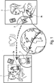
- FIG. 1 shows two related partners 1 and 2, each carrying a designed as a communication unit according to the invention ring 3 of a communication system comprising only two such communication units on the arm.
- the transmitting and receiving electronics of these two annular communication units 3 are inseparably paired with each other, which means that a message sent by one of the communication units can only be received by the other paired communication unit.
- the two related partners 1 and 2 live far apart from each other, but have the opportunity to talk about it Telecommunications system according to the invention to send the respective affection expressing messages.
- one of the partners touches a touch-sensitive surface of the ring 3 with the fingers or sweeps over in the circumferential direction, which is metrologically detected by the ring of this type of touch a message generated via a communication network, such as Mobile network according to the GSM standard, possibly including an Internet connection to the other communication unit 3 is sent, where this message is signaled by operating an actuator arranged in the ring as an output unit, which can be done here for example by a vibration motor, the ring worn on the arm vibrated, felt by the carrier 1.
- a vibration motor the ring worn on the arm vibrated, felt by the carrier 1.
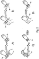
- FIG. 2 visualizes different ways of inputting and outputting messages.
- one of the partners sweeps over the surface of the ring with his fingers, which is detected by a touch-sensitive sensor within the ring and leads to the generation of a message to the other paired communication unit 3b, which after receiving the message through Vibration signaled this message.
- FIG. 2b It may also be provided to generate a message by another way of tactile actuation.
- the ring of the transmitting communication unit 3a is pressed so that different ring sections of a multi-part ring shift against each other, which is sensory detected in the ring and leads to sending a message to the received annular communication unit 3b, which signals the received message tactile, for example a circumferential length change or change in diameter of the ring, for example by variable-length actuators in the individual ring sections connecting connecting elements.
- Figure 2c visualizes the possibility of touching the touch-sensitive surface of a ring according to the invention, which is detected sensory by a touch-sensitive sensor inside the annular communication unit and in turn leads to sending a message to the paired communication unit 3b, where the received message is signaled tactile, eg by pulsed Controlling a vibration motor or an actuator causing a knock.
- Figure 2d visualizes a possibility according to which a thermal influence of a sensor, for example a temperature sensor near the ring surface is generated, for example, characterized in that the carrier of the annular communication unit puts his hand over the ring, whereby a heating of the ring takes place.
- a thermal influence of a sensor for example a temperature sensor near the ring surface
- the carrier of the annular communication unit puts his hand over the ring, whereby a heating of the ring takes place.
- a message may again be sent from the communication unit 3a to the communication unit 3b, whereby it may be provided that a signal is issued by a temperature increase.
- FIG. 3 shows a possible embodiment of an annular communication unit 3a and 3b, respectively.
- the illustrated communication unit is intended to be worn on the wrist.
- the communication unit 3a or 3b comprises a plurality of ring sections 4a, 4b and 4c, which are interconnected by connecting elements 5.
- the ring portions 4a, 4b and 4c may be formed, for example metallic, whereas the connecting elements 5 are formed of an elastomer.
- the entire electronics of the communication unit according to the invention in one of the ring sections namely the ring section 4c is integrated here.
- the thickness of the ring portion receiving the electronics may be variable in the circumferential direction to ensure that different electronic components can be accommodated therein.
- the embodiment shown here has near one of the connecting elements 5 to a vibration motor 6, by means of which an incoming message can be signaled, which is tactually perceived by the wearer of the ring.
- a power supply in the form of a battery 7 may be provided here.
- a touch-sensitive sensor 8 is arranged, by means of which a touch of the ring surface can be detected metrologically.
- a communication unit for receiving and sending messages may be arranged.
- the invention can also provide the various electronic parts of the entire electronics in each case to arrange another of the ring elements and these flexible to each other electrically contact, in particular by fasteners.
- the electronics is constructed in several parts comprising a plurality of electronic parts, which are interconnected by flexible printed circuit boards, so as to ensure that the electronics can be arranged in the circumferential direction of the ring of the ring curvature in the interior thereof.
Landscapes
- Engineering & Computer Science (AREA)
- Theoretical Computer Science (AREA)
- General Engineering & Computer Science (AREA)
- Computer Hardware Design (AREA)
- Human Computer Interaction (AREA)
- Signal Processing (AREA)
- General Physics & Mathematics (AREA)
- Computer Networks & Wireless Communication (AREA)
- Physics & Mathematics (AREA)
- Health & Medical Sciences (AREA)
- Computing Systems (AREA)
- General Health & Medical Sciences (AREA)
- Medical Informatics (AREA)
- Business, Economics & Management (AREA)
- General Business, Economics & Management (AREA)
- User Interface Of Digital Computer (AREA)
- Arrangements For Transmission Of Measured Signals (AREA)
Abstract
Description
- Die Erfindung betrifft ein Kommunikationssystem umfassend wenigstens zwei am Körper tragbare Kommunikationseinheiten ohne Sprach- oder Textkommunikationsmöglichkeit, jeweils mit einer Elektronik umfassend Sende- und Empfangseinheiten zur Kommunikation von Nachrichten zwischen den Kommunikationseinheiten, sowie jeweils wenigstens einer Ein- und Ausgabeeinheit zur taktilen oder thermischen Eingabe und taktilen oder thermischen Ausgabe von Nachrichten.
- Ein Kommunikationssystem dieser gattungsgemäßen Art ist beispielsweise bekannt aus der Publikation
US 8,326,378 B2 einer Konzerngesellschaft der Anmelderin. - Dort wird der Einsatz eines solchen Kommunikationssystems beschrieben bei zwei Personen, die sich über ein solches Kommunikationssystem zuneigungsbekundende Nachrichten zukommen lassen wollen, ohne hierfür sprachbasiert oder textbasiert kommunizieren zu müssen.
- Die genannte Publikation offenbart hierbei Kommunikationseinheiten in unterschiedlichster Form, die am Körper tragbar sind, z.B. in der Form von Ohrringen, Halsketten oder Uhren sowie auch von Kommunikationseinheiten, die nicht unmittelbar am Körper zu tragen sind aber mitgenommen werden können, wie z.B. Kugeln.
- Beschrieben wird beispielsweise das durch einfache Berührungen, Drücken oder Reiben einer solchen Kommunikationseinheit eine Nachricht von derjenigen Kommunikationseinheit an der diese Aktion ausgeführt wird an die andere Kommunikationseinheit übersendet wird und dort signalisiert wird, z.B. durch Vibration, Aufleuchten oder eine Temperaturänderung.
- Problematisch bei den hier beschriebenen Kommunikationseinheiten ist es, dass Kommunikationseinheiten solcher Formen beschrieben werden, die bei Personen beiderlei Geschlechts unterschiedliche Akzeptanz aufweisen.
- So ist es unter Männern beispielsweise weniger verbreitet Ohrringe oder Halsketten zu tragen im Vergleich zu Frauen, wohingegen Frauen eher Abstand davon nehmen Armbanduhren zu tragen.
- Am Körper nicht tragbare Kommunikationseinheiten wie die in dem Dokument benannten Kugeln unterliegen hingegen eher dem Verlustrisikos und werden darüber hinaus häufig nicht mitgeführt, so dass eingehende Nachrichten trotz einer eventuellen Signalisierung nicht wahrgenommen werden von der anderen Person.
- Darüber hinaus wünschen sich partnerschaftlich verbundene Personen eine technisch nicht trennbare Verbindung, um einander die fortdauernde Verbundenheit kundzutun.
- Vor diesem Hintergrund ist es eine Aufgabe der Erfindung ein Kommunikationssystem der grundsätzlich eingangs genannten und bekannten gattungsgemäßen Art derart weiterzubilden, dass hinsichtlich der am Körper tragbaren Kommunikationseinheiten bei den Personen geschlechtsunabhängig im Wesentlichen eine gleiche Akzeptanz vorliegt, solche Kommunikationseinheiten am Körper zu tragen, wobei nicht nur durch die ästhetische Gestaltung und die wertige Ausführung einer solchen Kommunikationseinheit die Wertschätzung des anderen Partners zum Ausdruck gebracht werden soll, sondern auch durch die technische Gestaltung die immer währenden Verbundenheit zwischen den Partnern vermittelt werden soll.
- Diese Aufgabe wird erfindungsgemäß dadurch gelöst, dass die am Körper tragbaren Kommunikationseinheiten jeweils als Ring oder Band zum Tragen an Körperextremitäten, insbesondere am Finger oder am Armgelenk oder am Hals ausgebildet sind und die Sende- und Empfangseinheiten nicht änderbar miteinander gepaart sind.
- Durch die Ausbildung der Kommunikationseinheiten in der Form eines jeweiligen Ringes oder Bandes zum Tragen an Körperextremitäten und insbesondere zum Tragen am Finger oder am Armgelenk wird sichergestellt, dass sowohl Männer als auch Frauen in gleicher Weise gerne eine solche derart ausgebildete Kommunikationseinheit am Körper tragen.
- Hierbei kann die Erfindung sogar vorsehen, dass bei einem Kommunikationssystem mit wenigstens zwei solchen am Körper tragbaren Kommunikationseinheiten eine der Kommunikationseinheiten als Fingerring und die andere als am Armgelenk zu tragender Ring ausgebildet ist. Auch kann eine als Band und die andere als Ring ausgebildet sein. Ebenso können die Kommunikationseinheiten alle als Ring zum Tragen am Finger oder auch alle als Ring zum Tragen am Armgelenk ausgebildet sein. In gleicher Weise können alle als Bänder ausgebildet sein.
- Die Sende- und Empfangseinheiten, die in den ringförmig oder bandförmig ausgebildeten Kommunikationseinheiten jeweils vorgesehen sind, sind erfindungsgemäß technisch nicht änderbar miteinander gepaart, was im Sinne der Erfindung bedeutet, dass eine von einer der Kommunikationseinheiten dieses Systems abgesendete Nachricht ausschließlich nur von der anderen gepaarten Kommunikationseinheit empfangen werden kann. Diese Paarung zwischen den Kommunikationseinheiten kann erfindungsgemäß nicht aufgelöst werden, so dass eine beziehungstechnische Verbundenheit zwischen den Partnern auch technisch in dem erfindungsgemäßen Kommunikationssystem realisiert ist.
- Für den Fall, dass sich die Beziehung der Partner lösen sollte, könnte keiner der Partner seine Kommunikationseinheit in Verbindung mit einem neuen Beziehungspartner nutzen.
- Ein Kommunikationssystem der erfindungsgemäßen Art eignet sich daher besonders gut als Wertschätzung und Verbundenheitsgeste eines der beiden Partner gegenüber dem anderen, um mittels des Kommunikationssystems auch über lange Entfernungen hinweg, insbesondere bei sogenannten typischen Fernbeziehungen jederzeit die Verbundenheit durch die kommunizierten und an der anderen Kommunikationseinheit signalisierten Nachrichten auszudrücken.
- Hierbei kann es vorgesehen sein, dass die Kommunikationseinheiten über ein Mobilfunknetzwerk unmittelbar miteinander kommunizieren, ohne andere Kommunikationseinheiten mobiler Art, wie beispielsweise Mobiltelefone in den Kommunikationsweg zwischenschalten zu müssen.
- Die Verwendung eines erfindungsgemäßen Kommunikationssystems in Form von zwei oder mehr ringförmigen oder bandförmigen Kommunikationseinheiten kann somit autark völlig losgelöst von jeglichen anderen Kommunikationsmöglichkeiten der beteiligten Partner realisiert werden, wenngleich auch die Kommunikation über zwischengeschaltete weitere Kommunikationsgeräte möglich ist.
- Dabei kann das Kommunikationssystem zwar regelmäßig zwei Kommunikationseinheiten für zwei in Beziehung stehende Partner vorsehen, es könnten jedoch auch mehr als zwei Kommunikationseinheiten eingesetzt werden, beispielsweise um einen familiären Verbund von mehreren Personen technisch symbolisiert darzustellen.
- Eine jeweilige Kommunikationseinheit kann bei der vorliegenden Erfindung wenigstens einen Sensor umfassen, mittels dem z.B. eine von dem Träger des Ringes oder Bandes stammende Berührung (insbesondere tippend oder streichend) des Ringes oder Bandes ermittelbar ist, wobei der wenigstens eine Sensor unterhalb einer die äußere Ansichtsfläche des Ringes oder Bandes bildenden Oberfläche angeordnet ist.
- Hierdurch wird sichergestellt, dass ein solcher Sensor das äußere Erscheinungsbild eines Ringes oder Bandes nicht verändert, da eine Berührung mittels des Sensors durch die Ansichtsfläche des Ringes oder Bandes hindurch technisch wahrgenommen werden kann. Beispielsweise kann hierfür der Sensor als kapazitiver Sensor ausgebildet sein.
- Besonders diese Ausgestaltung hat den Vorteil, dass sich die äußere optische Erscheinung einer Kommunikationseinheit des erfindungsgemäßen Systems nicht anpassen muss an irgendwelche technischen Gegebenheiten der Kommunikationseinheit, sondern die optische Erscheinung im Wesentlichen ausschließlich aus ästhetischen Erwägungen heraus entwickelt werden kann.
- Das Kommunikationssystem bzw. eine jegliche Kommunikationseinheit kann hierbei eingerichtet sein nach einer Berührung der berührungssensitiven Fläche mittels des vorgenannten Sensors eine Nachricht zu generieren und über ein Telekommunikationsnetzwerk, wie beispielsweise das Mobilfunknetz (z.B. GSM, UMTS, LTE etc.) an die andere technisch gepaarte Kommunikationseinheit zu versenden, wo diese Nachricht nach Empfang signalisiert wird, z.B. durch eine Vibration oder eine sonstige nicht sprachliche und nicht textliche Signalisierung, somit ggf. auch durch eine Erwärmung oder auch eine optische Signalisierung.
- Die Erfindung kann hier auch vorsehen, in einem jeweiligen Ring oder Band einen Temperatursensor anzuordnen, wobei dieser bevorzugt ring- bzw. bandaußenseitig, d.h. vom Träger des Ringes / Bandes abgewandt angeordnet wird, um hierdurch die Möglichkeit zu erschließen Temperaturerhöhungen zu detektieren, die dadurch hervorgerufen werden, dass der Träger des Ringes / Bandes den Ring bzw. das Band von außen körperlich abdeckt, z.B. durch Auflegen einer Hand, wodurch sich die Temperatur an der Oberfläche des Ringes / Bandes erhöht, was mittels des Temperatursensors und daran angeschlossener Elektronik des Ringes / Bandes messtechnisch ermittelbar ist, so dass aus dieser Temperaturerhöhung, insbesondere über eine ansonsten vorherrschende mittlere Umgebungstemperatur hinaus, eine Nachricht generiert werden kann, die an die andere gepaarte Kommunikationseinheit versendet wird und dort nach Empfang zu einer Signalisierung führt, z.B. einer solchen Signalisierung, die ebenso eine Temperaturerhöhung bewirkt, hier insbesondere mittels eines erwärmbaren Elementes, welches bevorzugt ringinnenseitig / bandinnenseitig angeordnet ist, also an der zum Körper weisenden Seite des Ringes/Bandes, damit eine solche Temperaturerhöhung leicht und einfach wahrgenommen wird von dem Träger, der die Nachricht empfängt.
- Die Erfindung kann weiterhin vorsehen, dass die Elektronik in einer jeweiligen als Ring oder Band ausgebildeten Kommunikationseinheit eingerichtet ist, mittels wenigstens eines Sensors in Abhängigkeit von Daten dieses wenigstens einen Sensors den aktuellen Tragestatus zwischen "aktuell getragen" und "aktuell nicht getragen" zu unterscheiden.
- Ein solcher Sensor kann beispielweise als Temperatursensor (z.B. innenseitig zum Körper des Trägers gewandt) oder Bewegungs- bzw. Beschleunigungssensor ausgebildet sein. Es kann besonders bei Unterschreiten einer Grenztemperatur an diesem Sensor oder sofern keine Bewegungs- oder Beschleunigungsmesswerte ermittelt werden, aus diesen Daten die Information abgeleitet werden, dass die Kommunikationseinheit aktuell nicht am Körper getragen wird.
- Bei dieser Ausführung kann die Elektronik eines jeweiligen Ringes / Bandes weiterhin eingerichtet sein, eine vom anderen Ring/Band empfangene Nachricht beim vorliegenden Status, der besagt, dass der Ring / das Band aktuell nicht getragen ist, die empfangene Nachricht zu speichern und erst dann zu signalisieren, wenn der Status auf "aktuell getragen" wechselt, was beispielsweise dadurch festgestellt werden kann, das eine gemessene Temperatur über einen gespeicherten Grenzwert oder aber Bewegungs- bzw. Beschleunigungsdaten, insbesondere oberhalb vom gespeicherten Grenzwerten, festgestellt werden, so dass die Elektronik hieraus schließt, dass der Ring / das Band nunmehr wieder getragen wird und die Nachricht signalisiert. So kann vermieden werden, dass bei einem nicht getragenen Ring / Band eingehende Nachrichten zwar signalisiert aber von dem anderen Partner nicht wahrgenommen werden.
- Sensoren beider Art (Temperatur und Beschleunigung) können auch kombiniert werden, z.B. um festzustellen, oder der Träger z.B. schläft und deshalb eine empfangene Nachricht verpassen würde. Zeigt zwar der Tempertursensor an, dass der Ring / das Band getragen wird, der Beschleunigungssensor jedoch mit seinen Messwerten anzeigt, dass der Ring / das Band nicht oder wenig bewegt wird (Werte z.B. unterhalb gespeichertem Grenzwert und/oder grenzwertüberschreitende Werte zeitlich zu groß beabstandet), so kann hieraus eine Wahrscheinlichkeit ermittelt werden, dass der Träger schläft und eine Signalisierung einer empfangenen Nachricht unterbleiben, bis dass eine Wahrscheinlichkeit für ein Erwachen vorliegt.
- Konstruktiv kann die Erfindung beispielsweise vorsehen, dass die Ringe oder Bänder in wenigstens zwei Elemente unterteilt sind, wobei eines der Elemente die Elektronik umfasst und die anderen Elementen nach Kundenwunsch aus mehreren designverschiedenen Elementen wählbar sind.
- So kann der Erwerber oder die Erwerber eines solchen Systems beim Kauf die später zu tragenden Ringe bzw. Bänder trotz gleichbleibender Elektronikausstattung hinsichtlich verschiedener Designvarianten wählen und somit dem eigenen ästhetischen Geschmack anpassen.
- Die Erfindung kann unabhängig von der vorgenannten Ausführung auch vorsehen, dass ein jeweiliger Ringe oder jeweiliges Band in Umfangsrichtung in wenigstens zwei, beispielsweise drei verbundene Abschnitte unterteilt ist. Diese Abschnitte können beispielsweise über Verbindungselemente miteinander verbunden sein, z.B. elastomere Verbindungselemente. Z.B. kann hierdurch auch die Möglichkeit erschlossen werden, die Umfangslänge eines solchen Ringes / Bandes aufgrund der Flexibilität in Grenzen anzupassen oder auch die bevorzugt elastomeren Verbindungselemente technisch zu funktionalisieren.
- Insbesondere dann, wenn ein Ring / Band mit mehreren Abschnitten und diese verbindenden Verbindungselementen ausgeführt ist kann dieser Ring oder dieses Band konstruktiv so ausgebildet werden, dass ein solcher Ring / solches Band aus einem zunächst einstückigen Ring / Band gebildet wird durch Entfernen von Abschnitten und Ersetzung dieser entfernten Abschnitte durch Verbindungselemente die jeweils der Form der entfernten Abschnitte entsprechen. So kann ein Ring oder Band aus mehreren Abschnitte und dieseverbindenden Verbindungselementen geschaffen werden, welcher/ welches vollständig in seiner äußeren Erscheinung dem ursprünglichen einstückigen Ring / Band gleichkommt.
- Die Erfindung kann hier in einer möglichen Ausführung beispielweise vorsehen, dass die gesamte Elektronik eines jeweiligen Ringes/Bandes in einem einzigen der mehreren Abschnitte angeordnet ist. Insbesondere bei dieser Ausführung kann es vorgesehen sein, dass eine Ausgabeeinheit angrenzend an ein Verbindungselement, bevorzugt ein elastomeres Verbindungselement angeordnet ist. Eine solche Ausgabeeinheit kann beispielsweise durch einen Vibrationsmotor ausgebildet sein, der nach Empfang einer Nachricht von dem anderen gepaarten Ring/Band eine Vibration hervorruft, die aufgrund der elastischen Ankopplung eines benachbarten Abschnittes über das elastische Verbindungselement besonders gut wahrnehmbar ist.
- Bei einer Ausbildung eines jeweiligen Ringes / Bandes in Umfangsrichtung durch wenigstens zwei miteinander verbundene Abschnitte, wobei separate Verbindungselemente zwischen diesen Abschnitten vorgesehen sind, kann gemäß einer Weiterbildung der Erfindung auch in wenigstens eines der Verbindungselemente zwischen den Abschnitten eine Ein- und/oder Ausgabeeinheit umfassen wofür beispielsweise ein mechanischer Sensor in einem solchen Verbindungselement angeordnet ist, mit dem eine Verlagerung von Abschnitten gegeneinander messbar ist und/oder ein mechanischer Aktor in einem solchen Verbindungselement angeordnet ist, mittels dem eine Verlagerung von Abschnitten gegeneinander bewirkbar ist, beispielsweise wobei ein solcher Aktor als Vibrationsmotor oder als längenveränderbares Element ausgebildet ist. Verbindungselemente die zur Verbindung von Abschnitten dienen weisen dabei bevorzugt in Umfangsrichtung eines geringere Länge auf, als die durch diese Verbindungselemente verbundene Abschnitte und sind gemäß einer möglichen Ausführung auch aus einem anderen Material, wie beispielsweise vorgenannt aus einem elastomeren Material ausgebildet, wohingegen die verbundenen Abschnitte bevorzugt aus einem anderen Material und besonders bevorzugt aus einem Metall ausgebildet sind, wie z.B. einem Edelmetall.
- Die Erfindung kann weiterhin vorsehen, dass die gesamte Elektronik eines jeweiligen Ringes / Bandes in mehrere Elektronikteile unterteilt ist, wobei die einzelnen Elektronikteile untereinander flexibel elektronisch kontaktiert sind, wie beispielsweise mittels flexibler Leiterplatten, z.B. solcher aus Polyimid, die entsprechende verbindende Leiterbahnen aufweisen. Hier können die einzelnen Elektronikteile auf jeweils separierten Leiterplatten realisiert sein.
- Bei einer Ausbildung eines Ringes / Bandes mit mehreren Abschnitten kann die Erfindung weiterhin vorsehen, dass jedes Elektronikteil in einem anderen der Abschnitte angeordnet ist, wobei insbesondere die Elektronikteile benachbarter Abschnitte durch die Verbindungselemente hindurch flexibel elektrisch kontaktiert sind.
- Ausführungsbeispiele der Erfindung werden nachfolgend beschrieben. Die
Figur 1 zeigt zwei in Beziehung zueinander stehende Partner 1 und 2 die jeweils einen als erfindungsgemäße Kommunikationseinheit ausgebildeten Ring 3 eines Kommunikationssystems umfassend lediglich zwei solcher Kommunikationseinheiten am Arm tragen. - Die Sende- und Empfangselektronik dieser beiden ringförmigen Kommunikationseinheiten 3 ist untrennbar miteinander gepaart, was bedeutet, dass eine von einer der Kommunikationseinheiten abgesendete Nachricht nur von der anderen gepaarten Kommunikationseinheit empfangbar ist.
- In diesem Beispiel leben die beiden in Beziehung stehenden Partner 1 und 2 örtlich weit voneinander entfernt haben jedoch die Möglichkeit sich über das erfindungsgemäße Telekommunikationssystem die jeweilige Zuneigung ausdrückende Nachrichten zukommen zu lassen.
- Hierfür kann es die Erfindung vorsehen, dass einer der Partner eine berührungssensitive Fläche des Ringes 3 mit den Fingern berührt oder in Umfangsrichtung überstreicht, wodurch von dem Ring der diese Art der Berührung messtechnisch erfasst eine Nachricht generiert wird, die über ein Kommunikationsnetzwerk, wie beispielsweise das Mobilfunknetzwerk nach dem GSM Standard ggf. unter Einbeziehung einer Internetverbindung an die andere Kommunikationseinheit 3 versendet wird, wo diese Nachricht signalisiert wird durch Betätigung eines in dem Ring angeordneten Aktors als Ausgabeeinheit, was hier beispielsweise durch einen Vibrationsmotor erfolgen kann, der den am Arm getragenen Ring in eine Vibration versetzt, die der Träger 1 spürt. Hierdurch empfängt der Partner 1 eine taktile Nachricht, die ihm anzeigt, dass seine Partnerin 2 gerade im Augenblick an ihn denkt.
- Die
Figur 2 visualisiert verschiedene Möglichkeiten der Ein- und Ausgabe von Nachrichten. GemäßFigur 2a kann es beispielsweise vorgesehen sein, dass einer der Partner über die Oberfläche des Ringes mit den Fingern herüberstreicht, was durch einen berührungsempfindlichen Sensor innerhalb des Ringes messtechnisch erfasst wird und zur Generierung einer Nachricht an die andere gepaarte Kommunikationseinheit 3b führt, die nach Empfang der Nachricht durch Vibration diese Nachricht signalisiert. - Gemäß
Figur 2b kann es auch vorgesehen sein eine Nachricht durch eine andere Art und Weise der taktilen Betätigung zu generieren. Beispielsweise wird hier der Ring der sendenden Kommunikationseinheit 3a gedrückt, so dass sich verschiedene Ringabschnitte eines mehrteiligen Ringes gegeneinander verlagern, was sensorisch im Ring festgestellt wird und zu Absendung einer Nachricht an die empfangene ringförmige Kommunikationseinheit 3b führt, die die empfangene Nachricht taktil signalisiert, beispielsweise durch eine Umfangslängenänderung bzw. Durchmesseränderung des Ringes, z.B. durch längenveränderliche Aktoren in den die einzelnen Ringabschnitte verbindenden Verbindungselementen. -
Figur 2c visualisiert die Möglichkeit die berührungssensitiven Fläche eines erfindungsgemäßen Ringes tippend zu berühren, was durch einen berührungssensitiven Sensor im Inneren der ringförmigen Kommunikationseinheit sensorisch festgestellt wird und wiederum zur Absendung einer Nachricht zu der gepaarten Kommunikationseinheit 3b führt, wo die empfangene Nachricht taktil signalisiert wird, z.B. durch gepulstes Ansteuern eines Vibrationsmotors oder eines ein Klopfen bewirkenden Aktors. -
Figur 2d visualisiert eine Möglichkeit, gemäß der eine thermische Beeinflussung eines Sensors, beispielsweise eines Temperatursensors nahe der Ringoberfläche erzeugt wird, z.B. dadurch dass der Träger der ringförmigen Kommunikationseinheit seine Hand über den Ring legt, wodurch eine Erwärmung des Ringes erfolgt. Bei einer festgestellten Erwärmung z.B. bis über eine Grenztemperatur hinweg, die im Ring gespeichert sein kann, kann wiederum eine Nachricht ausgehend von der Kommunikationseinheit 3a an die Kommunikationseinheit 3b erfolgen wobei es vorgesehen sein kann hier eine Signalisierung durch eine Temperaturerhöhung vorzunehmen. -
Figur 3 zeigt eine mögliche Ausführung einer ringförmigen Kommunikationseinheit 3a bzw. 3b. Im vorliegenden Fall ist die dargestellte Kommunikationseinheit vorgesehen, um am Handgelenk getragen zu werden. Die Kommunikationseinheit 3a bzw. 3b umfasst mehrere Ringabschnitte 4a, 4b und 4c, die durch Verbindungselemente 5 miteinander verbunden sind. Hier können die Ringabschnitte 4a, 4b und 4c z.B. metallisch ausgebildet sein, wohingegen die Verbindungselemente 5 aus einem Elastomer ausgebildet sind. - Bei der hier dargestellten Ausführung ist es vorgesehen, dass die gesamte Elektronik der erfindungsgemäßen Kommunikationseinheit in einem der Ringabschnitte nämlich hier dem Ringabschnitt 4c integriert ist. Die Dicke des Ringabschnittes, der die Elektronik aufnimmt kann hier in Umfangsrichtung variabel sein, um sicherzustellen, dass unterschiedlich stark aufbauende Elektronikkomponenten hierin Platz finden.
- Die hier gezeigte Ausführung weist nahe einer der Verbindungselemente 5 einen Vibrationsmotor 6 auf, mittels dem einer einkommenden Nachricht signalisiert werden kann, was von dem Träger des Ringes taktil wahrgenommen wird. Gegenüberliegend nahe einem anderen Verbindungselement 5 kann hier eine Energieversorgung in Form einer Batterie 7 vorgesehen sein.
- Unterhalb der äußeren Oberfläche 4d des Ringelementes 4c wird ein berührungssensitiver Sensor 8 angeordnet, mittels dem eine Berührung der Ringoberfläche messtechnisch erfasst werden kann.
- Beispielsweise geschichtet unterhalb der berührungssensitiven Fläche, durch einen kapazitiven berührungsempfindlichen Sensor ausgebildet werden kann, kann eine Kommunikationseinheit zum Empfang und Versenden von Nachrichten angeordnet sein.
- Bei einer hier nicht visualisierten Ausführung einer ringförmigen Kommunikationseinheit, die in mehrere Ringabschnitte unterteilt ist kann die Erfindung auch vorsehen die verschiedenen Elektronikteile der gesamten Elektronik jeweils in einem anderen der Ringelemente anzuordnen und diese flexibel untereinander elektrisch zu kontaktieren, insbesondere durch Verbindungselemente hindurch.
- Auch bei der hier dargestellten
Figur 3 ist die Elektronik mehrteilig aufgebaut umfassend mehrere Elektronikteile, die durch flexible Leiterplatten miteinander verbunden sind, um so zu gewährleisten, dass die Elektronik in der Umfangsrichtung des Ringes der Ringkrümmung folgend in dessen Inneren angeordnet werden kann.
Claims (12)
- Kommunikationssystem umfassend wenigstens zwei am Körper tragbare Kommunikationseinheiten (3a, 3b), ohne Sprach- oder Textkommunikationsmöglichkeit, jeweils mit einer Elektronik umfassend Sende- und Empfangseinheiten zur Kommunikation von Nachrichten zwischen den Kommunikationseinheiten sowie jeweils wenigstens einer Ein- und Ausgabeeinheit zur taktilen oder thermischen Eingabe und taktilen oder thermischen Ausgabe von Nachrichten, dadurch gekennzeichnet, dass die Kommunikationseinheiten (3a, 3b) jeweils als Ring oder Band zum Tragen an Körperextremitäten, insbesondere am Finger oder Armgelenk oder am Hals ausgebildet sind und die Sende- und Empfangseinheiten nicht änderbar miteinander gepaart sind.
- Kommunikationssystem nach Anspruch 1, dadurch gekennzeichnet, dass die Kommunikationseinheiten in wenigstens zwei Elemente unterteilt sind, wobei eines der Elemente die Elektronik aufweist und die anderen Elemente nach Kundenwunsch aus mehreren design-verschiedenen Elementen wählbar sind.
- Kommunikationssystem nach einem der vorherigen Ansprüche, dadurch gekennzeichnet, dass die ring- oder bandförmigen Kommunikationseinheiten in Umfangsrichtung in wenigstens zwei verbundene Abschnitte (4a, 4b, 4c) unterteilt sind, insbesondere wobei die Abschnitte über Verbindungselemente (5) verbunden sind, insbesondere mittels elastomeren Verbindungselementen.
- Kommunikationssystem nach einem der vorherigen Ansprüche, dadurch gekennzeichnet, dass ein jeweiliger Ring (3a, 3b) oder jeweiliges Band mit mehreren Abschnitten (4a, 4b, 4c) gebildet ist aus einem einstückigen Ring oder Band durch Entfernung von Abschnitten und Ersetzung dieser entfernten Abschnitte durch Verbindungselemente (5), insbesondere elastomere Verbindungselemente gleicher Form.
- Kommunikationssystem nach Anspruch 3 oder 4, dadurch gekennzeichnet, dass die gesamte Elektronik eines jeweiligen Ringes (3a, 3b) oder Bandes in einem einzigen (4c) der mehreren Abschnitte (4a, 4b, 4c) angeordnet ist.
- Kommunikationssystem nach Anspruch 3 bis 5, dadurch gekennzeichnet, dass eine Ausgabeeinheit (6) angrenzend an ein Verbindungselement (5) angeordnet ist.
- Kommunikationssystem nach Anspruch 3 oder 4, dadurch gekennzeichnet, dass wenigstens eines der Verbindungselemente (5) zwischen den Abschnitten (4a, 4b, 4c) eine Ein- und/oder Ausgabeeinheit umfasst, insbesondere einen mechanischen Sensor umfasst, mit dem eine Verlagerung von Abschnitten (4a, 4b, 4c) gegeneinander messbar ist und/oder einen mechanischen Aktor (6) umfasst, mittels dem eine Verlagerung von Abschnitten (4a, 4b, 4c) gegeneinander bewirkbar ist.
- Kommunikationssystem nach einem der vorherigen Ansprüche, dadurch gekennzeichnet, dass die gesamte Elektronik eines jeweiligen Ringes (3a, 3b) oder Bandes in mehrere Elektronikteile unterteilt ist, insbesondere wobei jedes Elektronikteil in einem anderen der Abschnitte angeordnet ist, wobei die Elektronikteile, insbesondere diejenigen benachbarter Abschnitte untereinander flexibel elektrisch kontaktiert sind, insbesondere mittels flexibler Leiterplatten.
- Kommunikationssystem nach einem der vorherigen Ansprüche, dadurch gekennzeichnet, dass die Elektronik in einem jeweiligen Ring (3a, 3b) oder Band eingerichtet ist mittels wenigstens eines Sensors in Abhängigkeit von Daten dieses wenigstens einen Sensors den aktuellen Tragestatus zwischen "aktuell getragen" und "aktuell nicht getragen" zu unterscheiden.
- Kommunikationssystem nach Anspruch 9, dadurch gekennzeichnet, dass der Sensor als Temperatur- oder Bewegungs- / Beschleunigungssensor ausgebildet ist.
- Kommunikationssystem nach Anspruch 9 oder 10, dadurch gekennzeichnet, dass die Elektronik eines jeweiligen Ringes (3a, 3b) oder Bandes eingerichtet ist, eine vom anderen Ring oder Band empfangene Nachricht beim vorliegenden Status "aktuell nicht getragen" zu speichern und erst zu signalisieren, wenn der Status auf "aktuell getragen" wechselt.
- Kommunikationssystem nach einem der vorherigen Ansprüche, dadurch gekennzeichnet, dass ein jeweiliger Ring (3a, 3b) oder jeweiliges Band wenigstens einen Sensor (8) umfasst, mittels dem eine Berührung des Ringes oder Bandes von dem Träger des Ringes oder Bandes ermittelbar ist, wobei der wenigstens eine Sensor unterhalb einer die äußere Ansichtsfläche des Ringes oder Bandes bildenden Oberfläche angeordnet ist.
Priority Applications (1)
| Application Number | Priority Date | Filing Date | Title |
|---|---|---|---|
| EP15001358.9A EP3091763B1 (de) | 2015-05-07 | 2015-05-07 | Kommunikationssystem mit wenigstens zwei am körper tragbaren kommunikationseinheiten |
Applications Claiming Priority (1)
| Application Number | Priority Date | Filing Date | Title |
|---|---|---|---|
| EP15001358.9A EP3091763B1 (de) | 2015-05-07 | 2015-05-07 | Kommunikationssystem mit wenigstens zwei am körper tragbaren kommunikationseinheiten |
Publications (2)
| Publication Number | Publication Date |
|---|---|
| EP3091763A1 true EP3091763A1 (de) | 2016-11-09 |
| EP3091763B1 EP3091763B1 (de) | 2018-02-21 |
Family
ID=53174761
Family Applications (1)
| Application Number | Title | Priority Date | Filing Date |
|---|---|---|---|
| EP15001358.9A Active EP3091763B1 (de) | 2015-05-07 | 2015-05-07 | Kommunikationssystem mit wenigstens zwei am körper tragbaren kommunikationseinheiten |
Country Status (1)
| Country | Link |
|---|---|
| EP (1) | EP3091763B1 (de) |
Citations (3)
| Publication number | Priority date | Publication date | Assignee | Title |
|---|---|---|---|---|
| US20100210323A1 (en) * | 2009-02-13 | 2010-08-19 | Maura Collins | Communication between devices using tactile or visual inputs, such as devices associated with mobile devices |
| US8643479B1 (en) * | 2012-04-09 | 2014-02-04 | John Donham | Wearable charms for use with a wireless client device and method of using the same |
| US20140340206A1 (en) * | 2013-05-17 | 2014-11-20 | Edward D. Bugg, JR. | Sensory messaging systems and related methods |
Family Cites Families (1)
| Publication number | Priority date | Publication date | Assignee | Title |
|---|---|---|---|---|
| US20150077234A1 (en) * | 2011-07-12 | 2015-03-19 | Aliphcom | System of wearable devices with sensors for synchronization of body motions based on haptic prompts |
-
2015
- 2015-05-07 EP EP15001358.9A patent/EP3091763B1/de active Active
Patent Citations (4)
| Publication number | Priority date | Publication date | Assignee | Title |
|---|---|---|---|---|
| US20100210323A1 (en) * | 2009-02-13 | 2010-08-19 | Maura Collins | Communication between devices using tactile or visual inputs, such as devices associated with mobile devices |
| US8326378B2 (en) | 2009-02-13 | 2012-12-04 | T-Mobile Usa, Inc. | Communication between devices using tactile or visual inputs, such as devices associated with mobile devices |
| US8643479B1 (en) * | 2012-04-09 | 2014-02-04 | John Donham | Wearable charms for use with a wireless client device and method of using the same |
| US20140340206A1 (en) * | 2013-05-17 | 2014-11-20 | Edward D. Bugg, JR. | Sensory messaging systems and related methods |
Non-Patent Citations (2)
| Title |
|---|
| ANONYMOUS: "TapTap vibrating wristband ensures your partner is ALWAYS with you | Daily Mail Online", 10 November 2013 (2013-11-10), XP055221076, Retrieved from the Internet <URL:http://www.dailymail.co.uk/sciencetech/article-2509886/TapTap-vibrating-wristband-ensures-partner-ALWAYS-you.html> [retrieved on 20151015] * |
| ANONYMOUS: "TapTap, a touch communication wristband by Woodenshark - Kickstarter", 16 March 2015 (2015-03-16), XP055220638, Retrieved from the Internet <URL:http://web.archive.org/web/20150316183611/https://www.kickstarter.com/projects/woodenshark/taptap-wristband-a-new-way-to-say-i-love-you> [retrieved on 20151014] * |
Also Published As
| Publication number | Publication date |
|---|---|
| EP3091763B1 (de) | 2018-02-21 |
Similar Documents
| Publication | Publication Date | Title |
|---|---|---|
| DE102014118073B3 (de) | Tragbare Vorrichtung | |
| DE202007018285U1 (de) | Tragbares Terminal | |
| SI23012A (sl) | Sistem in postopek za ocenjevanje psiholoških stanj na podlagi psihofizioloških odzivov in prenosteh stanj po različnih omrežjih | |
| DE202015103180U1 (de) | Verschlussstifte für eine tragbare Vorrichtung | |
| CN107088059A (zh) | 一种智能手环及app平台远程处理方法 | |
| DE102022209379A1 (de) | Uhrenarmband mit passformerkennung | |
| CN108766552A (zh) | 基于智能穿戴设备的健康服务系统、方法、终端及介质 | |
| DE102021006194A1 (de) | Weiblicher schnappverbinder sowie zugehörige vorrichtungen und verfahren | |
| EP3091763B1 (de) | Kommunikationssystem mit wenigstens zwei am körper tragbaren kommunikationseinheiten | |
| DE102015005729A1 (de) | Kommunikationssystem mit wenigstens zwei am Körper tragbaren Kommunikationseinheiten | |
| US20120234040A1 (en) | Bracelet | |
| EP1872309B1 (de) | Messwertaufnehmer mit zumindest einem saw-element | |
| EP1510987A2 (de) | Warnsystem sowie Verfahren zur Überwachung der Verfügbarkeit medizinischer Hilfe für einen Patienten | |
| Duker et al. | Determinants of maladaptive behavior of institutionalized mentally retarded individuals. | |
| DE102015116388A1 (de) | Elektronisches Gerät und Verfahren zur Informationsverarbeitung | |
| Warwick | A practical guide to posthumans | |
| CA1070957A (en) | Casing ring adapters for fitting small watch movements to larger size watch cases | |
| DE112018006642T5 (de) | Informationsverarbeitungsgerät, informationsverarbeitungsverfahren und informationsverarbeitungsverfahren programm | |
| CN206565433U (zh) | 一种智能指环 | |
| DE102010042524B4 (de) | Tragbares Gerät mit Bedieneinheit | |
| DE102014000338A1 (de) | Schmuckgegenstand | |
| CN207654149U (zh) | 可穿戴检测设备 | |
| EP4200678A1 (de) | Feldgerät, messanordnung sowie zum betreiben eins solchen feldgeräts | |
| US11983325B1 (en) | Digital communication assembly | |
| Roper-Hall | Traumatic cataract. |
Legal Events
| Date | Code | Title | Description |
|---|---|---|---|
| PUAI | Public reference made under article 153(3) epc to a published international application that has entered the european phase |
Free format text: ORIGINAL CODE: 0009012 |
|
| AK | Designated contracting states |
Kind code of ref document: A1 Designated state(s): AL AT BE BG CH CY CZ DE DK EE ES FI FR GB GR HR HU IE IS IT LI LT LU LV MC MK MT NL NO PL PT RO RS SE SI SK SM TR |
|
| AX | Request for extension of the european patent |
Extension state: BA ME |
|
| 17P | Request for examination filed |
Effective date: 20170509 |
|
| RBV | Designated contracting states (corrected) |
Designated state(s): AL AT BE BG CH CY CZ DE DK EE ES FI FR GB GR HR HU IE IS IT LI LT LU LV MC MK MT NL NO PL PT RO RS SE SI SK SM TR |
|
| GRAP | Despatch of communication of intention to grant a patent |
Free format text: ORIGINAL CODE: EPIDOSNIGR1 |
|
| INTG | Intention to grant announced |
Effective date: 20170914 |
|
| GRAS | Grant fee paid |
Free format text: ORIGINAL CODE: EPIDOSNIGR3 |
|
| GRAA | (expected) grant |
Free format text: ORIGINAL CODE: 0009210 |
|
| AK | Designated contracting states |
Kind code of ref document: B1 Designated state(s): AL AT BE BG CH CY CZ DE DK EE ES FI FR GB GR HR HU IE IS IT LI LT LU LV MC MK MT NL NO PL PT RO RS SE SI SK SM TR |
|
| REG | Reference to a national code |
Ref country code: GB Ref legal event code: FG4D Free format text: NOT ENGLISH |
|
| REG | Reference to a national code |
Ref country code: CH Ref legal event code: EP |
|
| REG | Reference to a national code |
Ref country code: AT Ref legal event code: REF Ref document number: 972976 Country of ref document: AT Kind code of ref document: T Effective date: 20180315 |
|
| REG | Reference to a national code |
Ref country code: IE Ref legal event code: FG4D Free format text: LANGUAGE OF EP DOCUMENT: GERMAN |
|
| REG | Reference to a national code |
Ref country code: DE Ref legal event code: R096 Ref document number: 502015003093 Country of ref document: DE |
|
| REG | Reference to a national code |
Ref country code: FR Ref legal event code: PLFP Year of fee payment: 4 |
|
| REG | Reference to a national code |
Ref country code: NL Ref legal event code: MP Effective date: 20180221 |
|
| REG | Reference to a national code |
Ref country code: LT Ref legal event code: MG4D |
|
| PG25 | Lapsed in a contracting state [announced via postgrant information from national office to epo] |
Ref country code: ES Free format text: LAPSE BECAUSE OF FAILURE TO SUBMIT A TRANSLATION OF THE DESCRIPTION OR TO PAY THE FEE WITHIN THE PRESCRIBED TIME-LIMIT Effective date: 20180221 Ref country code: NO Free format text: LAPSE BECAUSE OF FAILURE TO SUBMIT A TRANSLATION OF THE DESCRIPTION OR TO PAY THE FEE WITHIN THE PRESCRIBED TIME-LIMIT Effective date: 20180521 Ref country code: CY Free format text: LAPSE BECAUSE OF FAILURE TO SUBMIT A TRANSLATION OF THE DESCRIPTION OR TO PAY THE FEE WITHIN THE PRESCRIBED TIME-LIMIT Effective date: 20180221 Ref country code: LT Free format text: LAPSE BECAUSE OF FAILURE TO SUBMIT A TRANSLATION OF THE DESCRIPTION OR TO PAY THE FEE WITHIN THE PRESCRIBED TIME-LIMIT Effective date: 20180221 Ref country code: HR Free format text: LAPSE BECAUSE OF FAILURE TO SUBMIT A TRANSLATION OF THE DESCRIPTION OR TO PAY THE FEE WITHIN THE PRESCRIBED TIME-LIMIT Effective date: 20180221 Ref country code: FI Free format text: LAPSE BECAUSE OF FAILURE TO SUBMIT A TRANSLATION OF THE DESCRIPTION OR TO PAY THE FEE WITHIN THE PRESCRIBED TIME-LIMIT Effective date: 20180221 Ref country code: NL Free format text: LAPSE BECAUSE OF FAILURE TO SUBMIT A TRANSLATION OF THE DESCRIPTION OR TO PAY THE FEE WITHIN THE PRESCRIBED TIME-LIMIT Effective date: 20180221 |
|
| PG25 | Lapsed in a contracting state [announced via postgrant information from national office to epo] |
Ref country code: BG Free format text: LAPSE BECAUSE OF FAILURE TO SUBMIT A TRANSLATION OF THE DESCRIPTION OR TO PAY THE FEE WITHIN THE PRESCRIBED TIME-LIMIT Effective date: 20180521 Ref country code: GR Free format text: LAPSE BECAUSE OF FAILURE TO SUBMIT A TRANSLATION OF THE DESCRIPTION OR TO PAY THE FEE WITHIN THE PRESCRIBED TIME-LIMIT Effective date: 20180522 Ref country code: LV Free format text: LAPSE BECAUSE OF FAILURE TO SUBMIT A TRANSLATION OF THE DESCRIPTION OR TO PAY THE FEE WITHIN THE PRESCRIBED TIME-LIMIT Effective date: 20180221 Ref country code: SE Free format text: LAPSE BECAUSE OF FAILURE TO SUBMIT A TRANSLATION OF THE DESCRIPTION OR TO PAY THE FEE WITHIN THE PRESCRIBED TIME-LIMIT Effective date: 20180221 Ref country code: RS Free format text: LAPSE BECAUSE OF FAILURE TO SUBMIT A TRANSLATION OF THE DESCRIPTION OR TO PAY THE FEE WITHIN THE PRESCRIBED TIME-LIMIT Effective date: 20180221 |
|
| PG25 | Lapsed in a contracting state [announced via postgrant information from national office to epo] |
Ref country code: MT Free format text: LAPSE BECAUSE OF FAILURE TO SUBMIT A TRANSLATION OF THE DESCRIPTION OR TO PAY THE FEE WITHIN THE PRESCRIBED TIME-LIMIT Effective date: 20180221 |
|
| PG25 | Lapsed in a contracting state [announced via postgrant information from national office to epo] |
Ref country code: RO Free format text: LAPSE BECAUSE OF FAILURE TO SUBMIT A TRANSLATION OF THE DESCRIPTION OR TO PAY THE FEE WITHIN THE PRESCRIBED TIME-LIMIT Effective date: 20180221 Ref country code: EE Free format text: LAPSE BECAUSE OF FAILURE TO SUBMIT A TRANSLATION OF THE DESCRIPTION OR TO PAY THE FEE WITHIN THE PRESCRIBED TIME-LIMIT Effective date: 20180221 Ref country code: IT Free format text: LAPSE BECAUSE OF FAILURE TO SUBMIT A TRANSLATION OF THE DESCRIPTION OR TO PAY THE FEE WITHIN THE PRESCRIBED TIME-LIMIT Effective date: 20180221 Ref country code: AL Free format text: LAPSE BECAUSE OF FAILURE TO SUBMIT A TRANSLATION OF THE DESCRIPTION OR TO PAY THE FEE WITHIN THE PRESCRIBED TIME-LIMIT Effective date: 20180221 Ref country code: PL Free format text: LAPSE BECAUSE OF FAILURE TO SUBMIT A TRANSLATION OF THE DESCRIPTION OR TO PAY THE FEE WITHIN THE PRESCRIBED TIME-LIMIT Effective date: 20180221 |
|
| REG | Reference to a national code |
Ref country code: DE Ref legal event code: R097 Ref document number: 502015003093 Country of ref document: DE |
|
| PG25 | Lapsed in a contracting state [announced via postgrant information from national office to epo] |
Ref country code: CZ Free format text: LAPSE BECAUSE OF FAILURE TO SUBMIT A TRANSLATION OF THE DESCRIPTION OR TO PAY THE FEE WITHIN THE PRESCRIBED TIME-LIMIT Effective date: 20180221 Ref country code: SK Free format text: LAPSE BECAUSE OF FAILURE TO SUBMIT A TRANSLATION OF THE DESCRIPTION OR TO PAY THE FEE WITHIN THE PRESCRIBED TIME-LIMIT Effective date: 20180221 Ref country code: SM Free format text: LAPSE BECAUSE OF FAILURE TO SUBMIT A TRANSLATION OF THE DESCRIPTION OR TO PAY THE FEE WITHIN THE PRESCRIBED TIME-LIMIT Effective date: 20180221 Ref country code: DK Free format text: LAPSE BECAUSE OF FAILURE TO SUBMIT A TRANSLATION OF THE DESCRIPTION OR TO PAY THE FEE WITHIN THE PRESCRIBED TIME-LIMIT Effective date: 20180221 |
|
| REG | Reference to a national code |
Ref country code: CH Ref legal event code: PL |
|
| PLBE | No opposition filed within time limit |
Free format text: ORIGINAL CODE: 0009261 |
|
| STAA | Information on the status of an ep patent application or granted ep patent |
Free format text: STATUS: NO OPPOSITION FILED WITHIN TIME LIMIT |
|
| 26N | No opposition filed |
Effective date: 20181122 |
|
| REG | Reference to a national code |
Ref country code: BE Ref legal event code: MM Effective date: 20180531 |
|
| PG25 | Lapsed in a contracting state [announced via postgrant information from national office to epo] |
Ref country code: MC Free format text: LAPSE BECAUSE OF FAILURE TO SUBMIT A TRANSLATION OF THE DESCRIPTION OR TO PAY THE FEE WITHIN THE PRESCRIBED TIME-LIMIT Effective date: 20180221 |
|
| REG | Reference to a national code |
Ref country code: IE Ref legal event code: MM4A |
|
| PG25 | Lapsed in a contracting state [announced via postgrant information from national office to epo] |
Ref country code: CH Free format text: LAPSE BECAUSE OF NON-PAYMENT OF DUE FEES Effective date: 20180531 Ref country code: LI Free format text: LAPSE BECAUSE OF NON-PAYMENT OF DUE FEES Effective date: 20180531 Ref country code: SI Free format text: LAPSE BECAUSE OF FAILURE TO SUBMIT A TRANSLATION OF THE DESCRIPTION OR TO PAY THE FEE WITHIN THE PRESCRIBED TIME-LIMIT Effective date: 20180221 |
|
| PG25 | Lapsed in a contracting state [announced via postgrant information from national office to epo] |
Ref country code: LU Free format text: LAPSE BECAUSE OF NON-PAYMENT OF DUE FEES Effective date: 20180507 |
|
| PG25 | Lapsed in a contracting state [announced via postgrant information from national office to epo] |
Ref country code: IE Free format text: LAPSE BECAUSE OF NON-PAYMENT OF DUE FEES Effective date: 20180507 |
|
| PG25 | Lapsed in a contracting state [announced via postgrant information from national office to epo] |
Ref country code: BE Free format text: LAPSE BECAUSE OF NON-PAYMENT OF DUE FEES Effective date: 20180531 |
|
| PG25 | Lapsed in a contracting state [announced via postgrant information from national office to epo] |
Ref country code: TR Free format text: LAPSE BECAUSE OF FAILURE TO SUBMIT A TRANSLATION OF THE DESCRIPTION OR TO PAY THE FEE WITHIN THE PRESCRIBED TIME-LIMIT Effective date: 20180221 |
|
| PG25 | Lapsed in a contracting state [announced via postgrant information from national office to epo] |
Ref country code: PT Free format text: LAPSE BECAUSE OF FAILURE TO SUBMIT A TRANSLATION OF THE DESCRIPTION OR TO PAY THE FEE WITHIN THE PRESCRIBED TIME-LIMIT Effective date: 20180221 |
|
| PG25 | Lapsed in a contracting state [announced via postgrant information from national office to epo] |
Ref country code: MK Free format text: LAPSE BECAUSE OF NON-PAYMENT OF DUE FEES Effective date: 20180221 Ref country code: HU Free format text: LAPSE BECAUSE OF FAILURE TO SUBMIT A TRANSLATION OF THE DESCRIPTION OR TO PAY THE FEE WITHIN THE PRESCRIBED TIME-LIMIT; INVALID AB INITIO Effective date: 20150507 |
|
| PG25 | Lapsed in a contracting state [announced via postgrant information from national office to epo] |
Ref country code: IS Free format text: LAPSE BECAUSE OF FAILURE TO SUBMIT A TRANSLATION OF THE DESCRIPTION OR TO PAY THE FEE WITHIN THE PRESCRIBED TIME-LIMIT Effective date: 20180621 |
|
| REG | Reference to a national code |
Ref country code: AT Ref legal event code: MM01 Ref document number: 972976 Country of ref document: AT Kind code of ref document: T Effective date: 20200507 |
|
| PG25 | Lapsed in a contracting state [announced via postgrant information from national office to epo] |
Ref country code: AT Free format text: LAPSE BECAUSE OF NON-PAYMENT OF DUE FEES Effective date: 20200507 |
|
| PGFP | Annual fee paid to national office [announced via postgrant information from national office to epo] |
Ref country code: GB Payment date: 20260521 Year of fee payment: 12 |
|
| PGFP | Annual fee paid to national office [announced via postgrant information from national office to epo] |
Ref country code: DE Payment date: 20260520 Year of fee payment: 12 |
|
| PGFP | Annual fee paid to national office [announced via postgrant information from national office to epo] |
Ref country code: FR Payment date: 20260522 Year of fee payment: 12 |