EP3091646A1 - Linear electromechanical actuators - Google Patents
Linear electromechanical actuators Download PDFInfo
- Publication number
- EP3091646A1 EP3091646A1 EP16168736.3A EP16168736A EP3091646A1 EP 3091646 A1 EP3091646 A1 EP 3091646A1 EP 16168736 A EP16168736 A EP 16168736A EP 3091646 A1 EP3091646 A1 EP 3091646A1
- Authority
- EP
- European Patent Office
- Prior art keywords
- actuator
- linear motors
- carriage
- operatively connected
- recited
- Prior art date
- Legal status (The legal status is an assumption and is not a legal conclusion. Google has not performed a legal analysis and makes no representation as to the accuracy of the status listed.)
- Granted
Links
Images



Classifications
-
- H—ELECTRICITY
- H02—GENERATION; CONVERSION OR DISTRIBUTION OF ELECTRIC POWER
- H02K—DYNAMO-ELECTRIC MACHINES
- H02K41/00—Propulsion systems in which a rigid body is moved along a path due to dynamo-electric interaction between the body and a magnetic field travelling along the path
- H02K41/02—Linear motors; Sectional motors
-
- B—PERFORMING OPERATIONS; TRANSPORTING
- B64—AIRCRAFT; AVIATION; COSMONAUTICS
- B64C—AEROPLANES; HELICOPTERS
- B64C13/00—Control systems or transmitting systems for actuating flying-control surfaces, lift-increasing flaps, air brakes, or spoilers
- B64C13/24—Transmitting means
- B64C13/26—Transmitting means without power amplification or where power amplification is irrelevant
- B64C13/36—Transmitting means without power amplification or where power amplification is irrelevant fluid
-
- B—PERFORMING OPERATIONS; TRANSPORTING
- B64—AIRCRAFT; AVIATION; COSMONAUTICS
- B64C—AEROPLANES; HELICOPTERS
- B64C13/00—Control systems or transmitting systems for actuating flying-control surfaces, lift-increasing flaps, air brakes, or spoilers
- B64C13/24—Transmitting means
- B64C13/38—Transmitting means with power amplification
- B64C13/50—Transmitting means with power amplification using electrical energy
- B64C13/505—Transmitting means with power amplification using electrical energy having duplication or stand-by provisions
-
- H—ELECTRICITY
- H02—GENERATION; CONVERSION OR DISTRIBUTION OF ELECTRIC POWER
- H02K—DYNAMO-ELECTRIC MACHINES
- H02K11/00—Structural association of dynamo-electric machines with electric components or with devices for shielding, monitoring or protection
- H02K11/20—Structural association of dynamo-electric machines with electric components or with devices for shielding, monitoring or protection for measuring, monitoring, testing, protecting or switching
- H02K11/21—Devices for sensing speed or position, or actuated thereby
-
- H—ELECTRICITY
- H02—GENERATION; CONVERSION OR DISTRIBUTION OF ELECTRIC POWER
- H02K—DYNAMO-ELECTRIC MACHINES
- H02K16/00—Machines with more than one rotor or stator
-
- H—ELECTRICITY
- H02—GENERATION; CONVERSION OR DISTRIBUTION OF ELECTRIC POWER
- H02K—DYNAMO-ELECTRIC MACHINES
- H02K41/00—Propulsion systems in which a rigid body is moved along a path due to dynamo-electric interaction between the body and a magnetic field travelling along the path
- H02K41/02—Linear motors; Sectional motors
- H02K41/03—Synchronous motors; Motors moving step by step; Reluctance motors
- H02K41/031—Synchronous motors; Motors moving step by step; Reluctance motors of the permanent magnet type
-
- Y—GENERAL TAGGING OF NEW TECHNOLOGICAL DEVELOPMENTS; GENERAL TAGGING OF CROSS-SECTIONAL TECHNOLOGIES SPANNING OVER SEVERAL SECTIONS OF THE IPC; TECHNICAL SUBJECTS COVERED BY FORMER USPC CROSS-REFERENCE ART COLLECTIONS [XRACs] AND DIGESTS
- Y02—TECHNOLOGIES OR APPLICATIONS FOR MITIGATION OR ADAPTATION AGAINST CLIMATE CHANGE
- Y02T—CLIMATE CHANGE MITIGATION TECHNOLOGIES RELATED TO TRANSPORTATION
- Y02T50/00—Aeronautics or air transport
- Y02T50/40—Weight reduction
Definitions
- the present disclosure relates to actuators, and more particularly to actuators in fly-by-wire systems.
- Vehicles like aircraft commonly include fly-by-wire flight control systems. Such systems typically include an actuator for communicating between a flight control computer and a hydraulic system. Traditionally, geared ball screw actuators have been used. These actuators typically include a permanent magnet motor, a resolver, bearings, multiple gears, a ball screw and a recirculating ball spline. In aircraft flight control systems, triplex redundancy is required so that in case any one, or two of the actuators fail, the aircraft will remain under control. Traditional systems use mechanical disconnects or clutches to segregate a faulty actuator. These additional mechanical components not only increase the size cost and complexity of the system, they also provide another possible source of failure.
- An actuator includes a plurality of linear motors.
- a carriage is operatively connected to each linear motor to be driven by each of the linear motors.
- Each linear motor can include a stator and a forcer magnet.
- Each forcer magnet can be fixedly connected to the carriage.
- the carriage can include a leg operatively connected to a fastener for connecting the actuator to a hydraulic system.
- the actuator can include a plurality of bushings. Each bushing can be in sliding communication with the carriage to provide vertical and lateral support to the carriage.
- the actuator can include a housing surrounding the linear motors and the carriage. The housing can include a hole to accommodate for the linear motion of a leg of the carriage.
- the plurality of linear motors can include three linear motors.
- the carriage can include a plurality of legs. Each leg can correspond to a respective one of the linear motors.
- the actuator can include a plurality of linear variable differential transformers (LVDT) housed within the carriage to measure the absolute displacement of the carriage. Each LVDT can correspond to a respective one of the linear motors. Each leg can house a respective one of the LVDTs.
- LVDT linear variable differential transformers
- an actuator in another aspect, includes a plurality of linear motors.
- An output forcer rod is operatively connected to at least one of the linear motors to be driven by at least one of the linear motors.
- a position sensor is operatively connected to the output forcer rod to measure motion of the output forcer rod.
- At least one of the forcer magnets can be operatively connected to the output forcer rod to linearly drive the output forcer rod.
- the output forcer rod can include a mount to attach to an input linkage of a mechanical hydraulic servoactuator.
- the actuator can include a plurality of bushings. Each bushing can be operatively connected to the output forcer rod to provide vertical and lateral support to the output forcer rod.
- Actuator can include a housing surrounding the linear motors and the output forcer rod. The housing can include a hole to accommodate the linear motion of the output forcer rod.
- the position sensor can include a plurality of linear variable differential transformers (LVDT) within the housing operatively connected to the output forcer rod to measure the absolute displacement of the output forcer rod.
- the actuator can include a flight control surface of an aircraft operatively connected to the output forcer rod.
- a fly-by-wire system in another aspect, includes a plurality of electromechanical actuators. Each electromechanical actuator includes a plurality of linear motors. A flight control computer is operatively connected to the linear motors of each of the electromechanical actuators. The fly-by-wire system includes a plurality of hydraulic systems. Each hydraulic system is operatively coupled to a respective one of the electromechanical actuators. The fly-by-wire system can include a flight control surface of an aircraft operatively connected to at least one of the hydraulic systems.
- FIG. 1 a partial view of an exemplary embodiment of an aircraft, here, an exemplary embodiment of an aircraft as a vertical takeoff and landing (VTOL) aircraft in accordance with the disclosure is shown in Fig. 1 and is designated generally by reference character 10.
- VTOL vertical takeoff and landing
- the systems and methods described herein provide for increased reliability actuators that can be used in fly-by-wire systems, while reducing the amount of components and weight as compared with traditional actuator systems.
- VTOL aircraft 10 includes a main rotor system 12 and tail rotor system 14 supported by an airframe 19.
- Airframe 19 includes a gearbox 18 interconnecting an engine 20 with main rotor system 12 and tail rotor system 14.
- Main rotor system 12 is operatively connected to a swash plate 16.
- Swash plate 16 is operatively connected to hydraulic systems 101.
- VTOL aircraft 10 includes linear actuators 100, e.g. electromechanical actuators, operatively connected to the hydraulic systems 101, for example, a mechanical hydraulic servoactuator.
- VTOL aircraft configuration is illustrated and described in the disclosed embodiment, other configurations and/or machines, such as fixed wing aircraft, high speed compound rotary wing aircraft with supplemental translational thrust systems, dual contra-rotating, coaxial rotor system aircraft, turbo-props, tilt-rotors and tilt-wing aircraft, will also benefit from the present invention.
- a fly-by-wire system 103 includes three actuators 100.
- System 103 includes a flight control computer 105 operatively connected to each of actuators 100.
- Each actuator 100 of system 103 is operatively connected to a respective one of hydraulic systems 101.
- System 103 includes a flight control surface 17 of a rotorcraft, e.g. VTOL aircraft 10, operatively connected to at least one of three hydraulic systems 101 through swash plate 16.
- actuator 100 includes a housing 116.
- Housing 116 includes a connector side 117 and a forcer rod side 119.
- Housing connector side 117 includes motor power connectors 121 and signal connectors 123.
- Motor power connectors 121 are operatively connected between a motor drive 125, schematically shown in Fig. 3B , and respective linear motors 102, described below, to operatively connect linear motors 102 to motor drive 125.
- Actuator 100 includes a plurality of linear variable differential transformers (LVDT) 120, e.g. a position sensor, to measure the absolute displacement of linear motors 102.
- Signal connectors 123 operatively connect respective LVDTs 120 to flight control computer 105.
- Signal connectors 123 receive actuator position signals from each LVDT 120 and send them on to flight control computer 105, which compares the true position of actuator 100 to the commanded position from the pilot.
- LVDT linear variable differential transformers
- actuator 100 includes three linear motors 102. While three linear motors 102 are shown in actuator 100, it is contemplated that any suitable number of linear motors in parallel or series can be used to achieve the desired failure rate and level of redundancy, for example, one, two, four or five linear motors can be used.
- Each linear motor 102 includes a stator 106 and a forcer magnet 108. Each stator 106 has two halves, one on each side of forcer magnet 108. Each forcer magnet 108 is fixedly connected to carriage 104 so that carriage 104 moves between a retracted position ( Figs. 2 and 3A ) and an expanded position ( Fig. 4 ) during operation of each of linear motors 102.
- Actuator 100 includes a plurality of bushings 114.
- Bushings 114 are in sliding communication with legs 110, e.g. output forcer rods, of carriage 104 to provide vertical and lateral support to carriage 104, and in turn linear motors 102.
- legs 110 e.g. output forcer rods
- bushings 114 can be self-lubricated, fiber-reinforced Teflon bushings, or another suitable bushing.
- linear motors 102 provide increased reliability and reduced possibility of jamming, as compared with traditional actuators.
- LVDTs 120 of actuator 100 are housed within respective legs 110 of carriage 104 to measure the absolute displacement of carriage 104 and the absolute displacement of linear motors 102. LVDTs 120 are independent and provide the position sensing for both motor commutation and actuator output position. In the event that any one or two of linear motors 102 were to fail, the final motor would continue to drive carriage 104.
- signal connectors 123 each correspond to a respective LVDT 120.
- Each LVDT 120 is in electrical communication with flight control computer 105 through signal connectors 123 to convey the position of LVDTs 120 and carriage 104.
- the position of carriage 104 corresponds to a respective position of each one of linear motors 102.
- flight control computer 105 can appropriately adjust the power sent from motor drives 125 to linear motors 102 through motor power connectors 121 in order to achieve a desired position of carriage 104 along the longitudinal axis of actuator 100.
- the desired position of carriage 104 will depend on the input from the pilot or other control system.
- actuator 100 segregates three motor power connectors 121 and the three signal connectors 123, providing true redundancy between the systems, reducing the probability of failure due to a connector shorting out, or getting wet and losing connectivity.
- carriage 104 is shown in an extended position with respect to housing 116.
- housing 116 On forcer rod side 119, housing 116 includes holes 118 to accommodate for the linear motion of legs 110.
- Each leg 110 corresponds to a respective one of linear motors 102.
- One leg 110 of carriage 104 is operatively connected to a mount or fastener, for example, a turnbuckle 112, or the like.
- Turnbuckle 112 operatively connects actuator 100 and carriage 104 to a respective hydraulic system 101, schematically shown in Fig. 3B .
- Carriage 104 moves between retracted and expanded positions along the longitudinal axis of linear actuator 100 to drive hydraulic system 101.
- Hydraulic system 101 is operatively connected to swashplate 16 to drive one or more flight control surfaces 17.
Landscapes
- Engineering & Computer Science (AREA)
- Power Engineering (AREA)
- Automation & Control Theory (AREA)
- Aviation & Aerospace Engineering (AREA)
- Physics & Mathematics (AREA)
- Chemical & Material Sciences (AREA)
- Combustion & Propulsion (AREA)
- Electromagnetism (AREA)
- Microelectronics & Electronic Packaging (AREA)
- Linear Motors (AREA)
- Connection Of Motors, Electrical Generators, Mechanical Devices, And The Like (AREA)
Abstract
Description
- The present disclosure relates to actuators, and more particularly to actuators in fly-by-wire systems.
- Vehicles like aircraft commonly include fly-by-wire flight control systems. Such systems typically include an actuator for communicating between a flight control computer and a hydraulic system. Traditionally, geared ball screw actuators have been used. These actuators typically include a permanent magnet motor, a resolver, bearings, multiple gears, a ball screw and a recirculating ball spline. In aircraft flight control systems, triplex redundancy is required so that in case any one, or two of the actuators fail, the aircraft will remain under control. Traditional systems use mechanical disconnects or clutches to segregate a faulty actuator. These additional mechanical components not only increase the size cost and complexity of the system, they also provide another possible source of failure.
- Such conventional methods and systems have generally been considered satisfactory for their intended purpose. However, there is still a need in the art for improved actuator systems and methods. The present disclosure provides a solution for this need.
- An actuator includes a plurality of linear motors. A carriage is operatively connected to each linear motor to be driven by each of the linear motors.
- Each linear motor can include a stator and a forcer magnet. Each forcer magnet can be fixedly connected to the carriage. The carriage can include a leg operatively connected to a fastener for connecting the actuator to a hydraulic system. The actuator can include a plurality of bushings. Each bushing can be in sliding communication with the carriage to provide vertical and lateral support to the carriage. The actuator can include a housing surrounding the linear motors and the carriage. The housing can include a hole to accommodate for the linear motion of a leg of the carriage.
- It is contemplated that, the plurality of linear motors can include three linear motors. The carriage can include a plurality of legs. Each leg can correspond to a respective one of the linear motors. The actuator can include a plurality of linear variable differential transformers (LVDT) housed within the carriage to measure the absolute displacement of the carriage. Each LVDT can correspond to a respective one of the linear motors. Each leg can house a respective one of the LVDTs.
- In another aspect, an actuator includes a plurality of linear motors. An output forcer rod is operatively connected to at least one of the linear motors to be driven by at least one of the linear motors. A position sensor is operatively connected to the output forcer rod to measure motion of the output forcer rod.
- At least one of the forcer magnets can be operatively connected to the output forcer rod to linearly drive the output forcer rod. The output forcer rod can include a mount to attach to an input linkage of a mechanical hydraulic servoactuator. The actuator can include a plurality of bushings. Each bushing can be operatively connected to the output forcer rod to provide vertical and lateral support to the output forcer rod. Actuator can include a housing surrounding the linear motors and the output forcer rod. The housing can include a hole to accommodate the linear motion of the output forcer rod. The position sensor can include a plurality of linear variable differential transformers (LVDT) within the housing operatively connected to the output forcer rod to measure the absolute displacement of the output forcer rod. The actuator can include a flight control surface of an aircraft operatively connected to the output forcer rod.
- In another aspect, a fly-by-wire system includes a plurality of electromechanical actuators. Each electromechanical actuator includes a plurality of linear motors. A flight control computer is operatively connected to the linear motors of each of the electromechanical actuators. The fly-by-wire system includes a plurality of hydraulic systems. Each hydraulic system is operatively coupled to a respective one of the electromechanical actuators. The fly-by-wire system can include a flight control surface of an aircraft operatively connected to at least one of the hydraulic systems.
- These and other features of the systems and methods of the subject disclosure will become more readily apparent to those skilled in the art from the following detailed description of the preferred embodiments taken in conjunction with the drawings.
- So that those skilled in the art to which the subject disclosure appertains will readily understand how to make and use the devices and methods of the subject disclosure without undue experimentation, embodiments thereof will be described in detail herein below with reference to certain figures, wherein:
-
Fig. 1 is a schematic view of an exemplary embodiment of a vertical take-off and landing (VTOL) aircraft constructed in accordance with the present disclosure, showing actuators operatively connected to hydraulic systems and a flight control computer; -
Fig. 2 is a perspective view of one of the actuators in the VTOL aircraft ofFig. 1 , showing the actuator housing and the turnbuckle; -
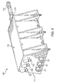
Fig. 3A is a cross-sectional perspective view of the actuator ofFig. 2 , showing three linear motors within the housing of the actuator; -
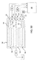
Fig. 3B is a schematic depiction of the actuator ofFig. 2 , showing the connections between the signal connectors and motor power connectors; and -
Fig. 4 is a perspective cut-away view of a portion of the actuator ofFig. 2 , showing a portion of the housing cut-away to expose the linear motors and carriage. - Reference will now be made to the drawings wherein like reference numerals identify similar structural features or aspects of the subject disclosure. For purposes of explanation and illustration, and not limitation, a partial view of an exemplary embodiment of an aircraft, here, an exemplary embodiment of an aircraft as a vertical takeoff and landing (VTOL) aircraft in accordance with the disclosure is shown in
Fig. 1 and is designated generally byreference character 10. Other embodiments of aircraft in accordance with the disclosure, or aspects thereof, are provided inFigs. 2-4 , as will be described. The systems and methods described herein provide for increased reliability actuators that can be used in fly-by-wire systems, while reducing the amount of components and weight as compared with traditional actuator systems. - As shown in
Fig. 1 ,VTOL aircraft 10 includes amain rotor system 12 andtail rotor system 14 supported by anairframe 19.Airframe 19 includes agearbox 18 interconnecting anengine 20 withmain rotor system 12 andtail rotor system 14.Main rotor system 12 is operatively connected to aswash plate 16.Swash plate 16 is operatively connected tohydraulic systems 101.VTOL aircraft 10 includeslinear actuators 100, e.g. electromechanical actuators, operatively connected to thehydraulic systems 101, for example, a mechanical hydraulic servoactuator. Although a particular VTOL aircraft configuration is illustrated and described in the disclosed embodiment, other configurations and/or machines, such as fixed wing aircraft, high speed compound rotary wing aircraft with supplemental translational thrust systems, dual contra-rotating, coaxial rotor system aircraft, turbo-props, tilt-rotors and tilt-wing aircraft, will also benefit from the present invention. - With continued reference to
Fig. 1 , a fly-by-wire system 103 includes threeactuators 100.System 103 includes aflight control computer 105 operatively connected to each ofactuators 100. Eachactuator 100 ofsystem 103 is operatively connected to a respective one ofhydraulic systems 101.System 103 includes aflight control surface 17 of a rotorcraft,e.g. VTOL aircraft 10, operatively connected to at least one of threehydraulic systems 101 throughswash plate 16. - With reference now to
Figs. 1 and2 ,actuator 100 includes ahousing 116.Housing 116 includes aconnector side 117 and aforcer rod side 119.Housing connector side 117 includesmotor power connectors 121 andsignal connectors 123.Motor power connectors 121 are operatively connected between amotor drive 125, schematically shown inFig. 3B , and respectivelinear motors 102, described below, to operatively connectlinear motors 102 tomotor drive 125.Actuator 100 includes a plurality of linear variable differential transformers (LVDT) 120, e.g. a position sensor, to measure the absolute displacement oflinear motors 102.Signal connectors 123 operatively connectrespective LVDTs 120 toflight control computer 105.Signal connectors 123 receive actuator position signals from eachLVDT 120 and send them on toflight control computer 105, which compares the true position ofactuator 100 to the commanded position from the pilot. - As shown in
Fig. 3A ,actuator 100 includes threelinear motors 102. While threelinear motors 102 are shown inactuator 100, it is contemplated that any suitable number of linear motors in parallel or series can be used to achieve the desired failure rate and level of redundancy, for example, one, two, four or five linear motors can be used. Eachlinear motor 102 includes astator 106 and aforcer magnet 108. Eachstator 106 has two halves, one on each side offorcer magnet 108. Eachforcer magnet 108 is fixedly connected tocarriage 104 so thatcarriage 104 moves between a retracted position (Figs. 2 and3A ) and an expanded position (Fig. 4 ) during operation of each oflinear motors 102.Actuator 100 includes a plurality ofbushings 114.Bushings 114 are in sliding communication withlegs 110, e.g. output forcer rods, ofcarriage 104 to provide vertical and lateral support tocarriage 104, and in turnlinear motors 102. Those skilled in the art will readily appreciate thatbushings 114 can be self-lubricated, fiber-reinforced Teflon bushings, or another suitable bushing. Those skilled in the art will readily appreciate thatlinear motors 102 provide increased reliability and reduced possibility of jamming, as compared with traditional actuators. - With continued reference to
Fig. 3A ,LVDTs 120 ofactuator 100 are housed withinrespective legs 110 ofcarriage 104 to measure the absolute displacement ofcarriage 104 and the absolute displacement oflinear motors 102.LVDTs 120 are independent and provide the position sensing for both motor commutation and actuator output position. In the event that any one or two oflinear motors 102 were to fail, the final motor would continue to drivecarriage 104. - As schematically shown in
Fig. 3B ,signal connectors 123 each correspond to arespective LVDT 120. EachLVDT 120 is in electrical communication withflight control computer 105 throughsignal connectors 123 to convey the position ofLVDTs 120 andcarriage 104. The position ofcarriage 104 corresponds to a respective position of each one oflinear motors 102. As such, by monitoring the position ofcarriage 104 andLVDTs 120 throughsignal connectors 123,flight control computer 105 can appropriately adjust the power sent frommotor drives 125 tolinear motors 102 throughmotor power connectors 121 in order to achieve a desired position ofcarriage 104 along the longitudinal axis ofactuator 100. The desired position ofcarriage 104 will depend on the input from the pilot or other control system. Those skilled in the art will readily appreciate thatactuator 100 segregates threemotor power connectors 121 and the threesignal connectors 123, providing true redundancy between the systems, reducing the probability of failure due to a connector shorting out, or getting wet and losing connectivity. - With reference now to
Figs. 1 and4 ,carriage 104 is shown in an extended position with respect tohousing 116. Onforcer rod side 119,housing 116 includesholes 118 to accommodate for the linear motion oflegs 110. Eachleg 110 corresponds to a respective one oflinear motors 102. Oneleg 110 ofcarriage 104 is operatively connected to a mount or fastener, for example, aturnbuckle 112, or the like.Turnbuckle 112 operatively connectsactuator 100 andcarriage 104 to a respectivehydraulic system 101, schematically shown inFig. 3B .Carriage 104 moves between retracted and expanded positions along the longitudinal axis oflinear actuator 100 to drivehydraulic system 101.Hydraulic system 101 is operatively connected to swashplate 16 to drive one or more flight control surfaces 17. - The systems and methods of the present disclosure, as described above and shown in the drawings, provide for actuators for fly-by-wire systems with superior properties including increased reliability and reduced weight. While the apparatus and methods of the subject disclosure have been shown and described with reference to VTOL aircraft, those skilled in the art will readily appreciate the systems and methods described herein are applicable to fixed wing aircraft, ground vehicles (e.g. construction and mining equipment), robotics, and process control machinery. Those skilled in the art will also readily appreciate that changes and/or modifications may be made to embodiments described above without departing from the spirit and scope of the subject disclosure.
Claims (15)
- An actuator (100) comprising:a plurality of linear motors (102); anda carriage (104) operatively connected to each linear motor to be driven by each of the linear motors.
- An actuator (100) as recited in claim 1, wherein each linear motor (102) includes a stator (106) and a forcer magnet (108), wherein each forcer magnet is fixedly connected to the carriage (104).
- An actuator (100) as recited in claim 1 or 2, wherein the carriage (104) includes a leg (110) operatively connected to a fastener for connecting the actuator to a hydraulic system.
- An actuator (100) as recited in claim 1, 2 or 3, further comprising a plurality of bushings (114), each bushing in sliding communication with the carriage (104) to provide vertical and lateral support to the carriage.
- An actuator (100) as recited in any preceding claim, further comprising a housing (116) surrounding the linear motors (102) and the carriage (104), preferably wherein the housing includes a hole (118) to accommodate for the linear motion of a leg (110) of the carriage.
- An actuator (100) as recited in any preceding claim, wherein the plurality of linear motors (102) includes three linear motors, and/or wherein the carriage (104) includes a plurality of legs (110), wherein each leg corresponds to a respective one of the linear motors.
- An actuator (100) as recited in any preceding claim, further comprising a plurality of linear variable differential transformers (LVDT) (120) housed within the carriage (104) to measure the absolute displacement of the carriage, wherein each LVDT corresponds to a respective one of the linear motors (102), preferably wherein the carriage includes a plurality of legs (110), wherein each leg corresponds to a respective one of the linear motors, and wherein each leg houses a respective one of the LVDTs.
- An actuator (100) comprising:a plurality of linear motors (102);an output forcer rod (110) operatively connected to at least one of the linear motors to be driven by at least one of the linear motors; anda position sensor operatively connected to the output forcer rod to measure motion of the output forcer rod.
- An actuator (100) as recited in claim 8, wherein each linear motor (102) includes a stator (106) and forcer magnet (108), wherein at least one of the forcer magnets is operatively connected to the output forcer rod (110) to linearly drive the output forcer rod, and/or wherein the output forcer rod includes a mount to attach to an input linkage of a mechanical hydraulic servoactuator.
- An actuator (100) as recited in claim 8 or 9, further comprising a plurality of bushings (114), each bushing operatively connected to the output forcer rod (110) to provide vertical and lateral support to the output forcer rod.
- An actuator as recited in claim 8, 9 or 10, further comprising a housing (116) surrounding the linear motors (102) and the output forcer rod (110).
- An actuator (100) as recited in claim 11, wherein the housing (116) includes a hole (118) to accommodate the linear motion of the output forcer rod (110), and/or wherein the position sensor comprises a plurality of linear variable differential transformers (LVDT) (120) within the housing operatively connected to the output forcer rod to measure the absolute displacement of the output forcer rod.
- An actuator (100) as recited in any of claims 8 to 12, further comprising a flight control surface (17) of an aircraft (10) operatively connected to the output forcer rod (110).
- A fly-by-wire system (103) comprising:a plurality of electromechanical actuators (100), each electromechanical actuator including a plurality of linear motors (102);a flight control computer (105) operatively connected to the linear motors of each of the electromechanical actuators; anda plurality of hydraulic systems (101), wherein each hydraulic system is operatively coupled to a respective one of the electromechanical actuators.
- A fly-by-wire system (103) as recited in claim 14, further comprising a flight control surface (17) of an aircraft (10) operatively connected to at least one of the hydraulic systems (101).
Applications Claiming Priority (1)
| Application Number | Priority Date | Filing Date | Title |
|---|---|---|---|
| US201562158074P | 2015-05-07 | 2015-05-07 |
Publications (2)
| Publication Number | Publication Date |
|---|---|
| EP3091646A1 true EP3091646A1 (en) | 2016-11-09 |
| EP3091646B1 EP3091646B1 (en) | 2018-07-25 |
Family
ID=55968936
Family Applications (1)
| Application Number | Title | Priority Date | Filing Date |
|---|---|---|---|
| EP16168736.3A Not-in-force EP3091646B1 (en) | 2015-05-07 | 2016-05-09 | Linear electromechanical actuators |
Country Status (3)
| Country | Link |
|---|---|
| US (1) | US10560011B2 (en) |
| EP (1) | EP3091646B1 (en) |
| JP (1) | JP2016220524A (en) |
Cited By (1)
| Publication number | Priority date | Publication date | Assignee | Title |
|---|---|---|---|---|
| EP3451514A1 (en) * | 2017-08-28 | 2019-03-06 | Hamilton Sundstrand Corporation | Actuator assembly |
Families Citing this family (6)
| Publication number | Priority date | Publication date | Assignee | Title |
|---|---|---|---|---|
| EP3107195A1 (en) * | 2015-06-16 | 2016-12-21 | InDriveTec AG | Linear motor drive system |
| US10730609B2 (en) * | 2016-03-03 | 2020-08-04 | Sikorsky Aircraft Corporation | Fly-by-wire retrofit kit |
| US11002569B2 (en) * | 2018-04-06 | 2021-05-11 | Hamilton Sundstrand Corporation | Actuator control system utilizing circuit card assembly |
| US20200259406A1 (en) * | 2019-02-07 | 2020-08-13 | Systems, Machines, Automation Components Corporation | Stacked actuator system |
| EP4100973A4 (en) | 2020-02-07 | 2024-05-22 | Systems, Machines, Automation Components Corporation | Multi-layer printed coil arrangement having variable-pitch printed coils |
| US12146553B2 (en) * | 2022-08-17 | 2024-11-19 | Raytheon Company | Sliding pin-yoke mechanism |
Citations (2)
| Publication number | Priority date | Publication date | Assignee | Title |
|---|---|---|---|---|
| US5801462A (en) * | 1995-03-31 | 1998-09-01 | Minolta Co., Ltd. | Linear motor and image reading apparatus |
| WO2014065308A1 (en) * | 2012-10-24 | 2014-05-01 | 株式会社日立製作所 | Linear motor and linear motor drive system |
Family Cites Families (25)
| Publication number | Priority date | Publication date | Assignee | Title |
|---|---|---|---|---|
| US4243358A (en) * | 1978-10-11 | 1981-01-06 | Textron | Control system for redundant swashplate drive |
| US4274808A (en) * | 1978-12-21 | 1981-06-23 | Textron, Inc. | Swashplate drive redundancy system |
| US4521707A (en) * | 1983-12-12 | 1985-06-04 | The Boeing Company | Triple redundant electromechanical linear actuator and method |
| SE457043B (en) * | 1985-04-29 | 1988-11-21 | Facit Ab | LINE STEP ENGINE |
| JP2651734B2 (en) * | 1990-02-19 | 1997-09-10 | 宇宙開発事業団 | Electromagnetic actuator |
| US7218019B2 (en) * | 2002-12-06 | 2007-05-15 | Foster-Miller, Inc | Linear reluctance motor |
| US8004127B2 (en) * | 2002-12-06 | 2011-08-23 | Foster-Miller, Inc. | Rotary reluctance motor |
| JP4517278B2 (en) * | 2004-01-20 | 2010-08-04 | 株式会社安川電機 | Coreless linear motor and canned linear motor |
| US7378765B2 (en) * | 2004-08-09 | 2008-05-27 | Oriental Motor Co., Ltd. | Cylinder-type linear motor and moving part thereof |
| CA2595256C (en) * | 2005-02-11 | 2009-12-29 | Bell Helicopter Textron Inc. | Dual motor dual concentric valve |
| MX2008014270A (en) * | 2006-05-08 | 2009-02-12 | Textron Innovations Inc | Ballistically tolerant linear hydraulic actuator. |
| DE102007017968A1 (en) * | 2007-04-11 | 2008-10-16 | Festo Ag & Co. Kg | Electric linear drive device |
| DE102007018258A1 (en) * | 2007-04-13 | 2008-11-06 | Festo Ag & Co. Kg | Electric linear drive device |
| US20100089053A1 (en) * | 2008-10-13 | 2010-04-15 | Honeywell International Inc. | Hybrid electromechanical/hydro-mechanical actuation control system |
| JP2012090467A (en) * | 2010-10-21 | 2012-05-10 | Seiko Epson Corp | Linear motor |
| CN201877980U (en) | 2010-11-22 | 2011-06-22 | 北京精密机电控制设备研究所 | Cylindrical redundancy linear-motion electromechanical actuator based on slender installation space |
| EP2543589B1 (en) * | 2011-07-06 | 2018-09-05 | Airbus Helicopters | Primary flight controls |
| EP2987228A2 (en) * | 2013-04-18 | 2016-02-24 | Nucleus Scientific, Inc. | Permanent magnet linear motors |
| JP6360774B2 (en) * | 2014-10-29 | 2018-07-18 | Kyb株式会社 | Linear actuator |
| JP5927266B2 (en) * | 2014-10-29 | 2016-06-01 | Kyb株式会社 | Linear actuator |
| US20160226349A1 (en) * | 2014-12-01 | 2016-08-04 | Hamilton Sundstrand Corporation | Electromechanical linear actuator |
| US10239610B2 (en) * | 2015-03-10 | 2019-03-26 | Bell Helicopter Textron Inc. | Compact linear hydraulic actuator |
| US10099776B2 (en) * | 2015-03-27 | 2018-10-16 | Hamilton Sundstrand Corporation | Rheologic fluid coupler for redundant linear electromechanical actuators |
| US10538310B2 (en) * | 2016-06-29 | 2020-01-21 | Parker-Hannifin Corporation | Near synchronous distributed hydraulic motor driven actuation system |
| US9933058B1 (en) * | 2016-09-29 | 2018-04-03 | Woodward, Inc. | Redundant extension linear actuator and methods of use |
-
2016
- 2016-05-04 US US15/146,139 patent/US10560011B2/en active Active
- 2016-05-09 JP JP2016093690A patent/JP2016220524A/en active Pending
- 2016-05-09 EP EP16168736.3A patent/EP3091646B1/en not_active Not-in-force
Patent Citations (2)
| Publication number | Priority date | Publication date | Assignee | Title |
|---|---|---|---|---|
| US5801462A (en) * | 1995-03-31 | 1998-09-01 | Minolta Co., Ltd. | Linear motor and image reading apparatus |
| WO2014065308A1 (en) * | 2012-10-24 | 2014-05-01 | 株式会社日立製作所 | Linear motor and linear motor drive system |
Cited By (3)
| Publication number | Priority date | Publication date | Assignee | Title |
|---|---|---|---|---|
| EP3451514A1 (en) * | 2017-08-28 | 2019-03-06 | Hamilton Sundstrand Corporation | Actuator assembly |
| US11001372B2 (en) | 2017-08-28 | 2021-05-11 | Hamilton Sundstrand Corporation | Actuator assembly |
| US11724795B2 (en) | 2017-08-28 | 2023-08-15 | Hamilton Sundstrand Corporation | Actuator assembly |
Also Published As
| Publication number | Publication date |
|---|---|
| US10560011B2 (en) | 2020-02-11 |
| JP2016220524A (en) | 2016-12-22 |
| EP3091646B1 (en) | 2018-07-25 |
| US20160329798A1 (en) | 2016-11-10 |
Similar Documents
| Publication | Publication Date | Title |
|---|---|---|
| US10560011B2 (en) | Linear electromechanical actuators | |
| EP2829471B1 (en) | Swashplateless coaxial rotary wing aircraft | |
| CN100534862C (en) | Dual motor dual concentric valve | |
| US7786684B2 (en) | Electromechanical flight control system and method for rotorcraft | |
| US9452831B2 (en) | Integration of rotary electrical actuator for swashplateless individual blade control | |
| US11548620B2 (en) | Electromechanically actuated control rod for flight vehicles | |
| EP3066007B1 (en) | Counter-rotating rotor system with stationary standpipe | |
| US10836478B2 (en) | Separation of collective and cyclic actuation | |
| EP2821343A1 (en) | Independent hydraulic control system for rotorcraft secondary rotor | |
| US20180273199A1 (en) | Aerodynamic control surface movement monitoring system for aircraft | |
| EP3406518B1 (en) | Linear sensor feel module for aircraft controls | |
| US11313391B2 (en) | Actuator system for a fly-by-wire aircraft | |
| US10023304B2 (en) | Tail rotor actuation system | |
| US11750121B2 (en) | Fault tolerant multiple rotary actuator assembly | |
| US12377974B2 (en) | Pylon tracking systems for tiltrotor aircraft | |
| EP2873613A1 (en) | Counter-rotating rotor system with static mast | |
| US20190283858A1 (en) | Selectively engageable aircraft driveshaft using friction plates | |
| EP3330570A1 (en) | Control system for an actuator | |
| CN1980010A (en) | Fault-tolerant electromechanical actuator | |
| US20250313333A1 (en) | Axially Aligned Triplex Linear Hydraulic Actuators | |
| US10173767B2 (en) | Aircraft with drive element coupled to gearbox housing exterior | |
| US11417995B2 (en) | Transmitting power and data together in a rotorcraft using a slip ring assembly | |
| NO344389B1 (en) | A system for variable blade pitch control and autorotation for electrically powered rotorcraft |
Legal Events
| Date | Code | Title | Description |
|---|---|---|---|
| PUAI | Public reference made under article 153(3) epc to a published international application that has entered the european phase |
Free format text: ORIGINAL CODE: 0009012 |
|
| AK | Designated contracting states |
Kind code of ref document: A1 Designated state(s): AL AT BE BG CH CY CZ DE DK EE ES FI FR GB GR HR HU IE IS IT LI LT LU LV MC MK MT NL NO PL PT RO RS SE SI SK SM TR |
|
| AX | Request for extension of the european patent |
Extension state: BA ME |
|
| STAA | Information on the status of an ep patent application or granted ep patent |
Free format text: STATUS: REQUEST FOR EXAMINATION WAS MADE |
|
| 17P | Request for examination filed |
Effective date: 20170509 |
|
| RBV | Designated contracting states (corrected) |
Designated state(s): AL AT BE BG CH CY CZ DE DK EE ES FI FR GB GR HR HU IE IS IT LI LT LU LV MC MK MT NL NO PL PT RO RS SE SI SK SM TR |
|
| RIC1 | Information provided on ipc code assigned before grant |
Ipc: H02K 16/00 20060101ALN20171222BHEP Ipc: H02K 41/03 20060101AFI20171222BHEP |
|
| GRAP | Despatch of communication of intention to grant a patent |
Free format text: ORIGINAL CODE: EPIDOSNIGR1 |
|
| STAA | Information on the status of an ep patent application or granted ep patent |
Free format text: STATUS: GRANT OF PATENT IS INTENDED |
|
| RIC1 | Information provided on ipc code assigned before grant |
Ipc: H02K 16/00 20060101ALN20180123BHEP Ipc: H02K 41/03 20060101AFI20180123BHEP |
|
| INTG | Intention to grant announced |
Effective date: 20180216 |
|
| GRAS | Grant fee paid |
Free format text: ORIGINAL CODE: EPIDOSNIGR3 |
|
| GRAA | (expected) grant |
Free format text: ORIGINAL CODE: 0009210 |
|
| STAA | Information on the status of an ep patent application or granted ep patent |
Free format text: STATUS: THE PATENT HAS BEEN GRANTED |
|
| AK | Designated contracting states |
Kind code of ref document: B1 Designated state(s): AL AT BE BG CH CY CZ DE DK EE ES FI FR GB GR HR HU IE IS IT LI LT LU LV MC MK MT NL NO PL PT RO RS SE SI SK SM TR |
|
| REG | Reference to a national code |
Ref country code: GB Ref legal event code: FG4D |
|
| REG | Reference to a national code |
Ref country code: CH Ref legal event code: EP |
|
| REG | Reference to a national code |
Ref country code: AT Ref legal event code: REF Ref document number: 1022828 Country of ref document: AT Kind code of ref document: T Effective date: 20180815 |
|
| REG | Reference to a national code |
Ref country code: IE Ref legal event code: FG4D |
|
| REG | Reference to a national code |
Ref country code: DE Ref legal event code: R096 Ref document number: 602016004204 Country of ref document: DE |
|
| REG | Reference to a national code |
Ref country code: NL Ref legal event code: MP Effective date: 20180725 |
|
| REG | Reference to a national code |
Ref country code: LT Ref legal event code: MG4D |
|
| PG25 | Lapsed in a contracting state [announced via postgrant information from national office to epo] |
Ref country code: NL Free format text: LAPSE BECAUSE OF FAILURE TO SUBMIT A TRANSLATION OF THE DESCRIPTION OR TO PAY THE FEE WITHIN THE PRESCRIBED TIME-LIMIT Effective date: 20180725 |
|
| REG | Reference to a national code |
Ref country code: AT Ref legal event code: MK05 Ref document number: 1022828 Country of ref document: AT Kind code of ref document: T Effective date: 20180725 |
|
| PG25 | Lapsed in a contracting state [announced via postgrant information from national office to epo] |
Ref country code: FI Free format text: LAPSE BECAUSE OF FAILURE TO SUBMIT A TRANSLATION OF THE DESCRIPTION OR TO PAY THE FEE WITHIN THE PRESCRIBED TIME-LIMIT Effective date: 20180725 Ref country code: PL Free format text: LAPSE BECAUSE OF FAILURE TO SUBMIT A TRANSLATION OF THE DESCRIPTION OR TO PAY THE FEE WITHIN THE PRESCRIBED TIME-LIMIT Effective date: 20180725 Ref country code: IS Free format text: LAPSE BECAUSE OF FAILURE TO SUBMIT A TRANSLATION OF THE DESCRIPTION OR TO PAY THE FEE WITHIN THE PRESCRIBED TIME-LIMIT Effective date: 20181125 Ref country code: AT Free format text: LAPSE BECAUSE OF FAILURE TO SUBMIT A TRANSLATION OF THE DESCRIPTION OR TO PAY THE FEE WITHIN THE PRESCRIBED TIME-LIMIT Effective date: 20180725 Ref country code: LT Free format text: LAPSE BECAUSE OF FAILURE TO SUBMIT A TRANSLATION OF THE DESCRIPTION OR TO PAY THE FEE WITHIN THE PRESCRIBED TIME-LIMIT Effective date: 20180725 Ref country code: BG Free format text: LAPSE BECAUSE OF FAILURE TO SUBMIT A TRANSLATION OF THE DESCRIPTION OR TO PAY THE FEE WITHIN THE PRESCRIBED TIME-LIMIT Effective date: 20181025 Ref country code: GR Free format text: LAPSE BECAUSE OF FAILURE TO SUBMIT A TRANSLATION OF THE DESCRIPTION OR TO PAY THE FEE WITHIN THE PRESCRIBED TIME-LIMIT Effective date: 20181026 Ref country code: NO Free format text: LAPSE BECAUSE OF FAILURE TO SUBMIT A TRANSLATION OF THE DESCRIPTION OR TO PAY THE FEE WITHIN THE PRESCRIBED TIME-LIMIT Effective date: 20181025 Ref country code: RS Free format text: LAPSE BECAUSE OF FAILURE TO SUBMIT A TRANSLATION OF THE DESCRIPTION OR TO PAY THE FEE WITHIN THE PRESCRIBED TIME-LIMIT Effective date: 20180725 Ref country code: SE Free format text: LAPSE BECAUSE OF FAILURE TO SUBMIT A TRANSLATION OF THE DESCRIPTION OR TO PAY THE FEE WITHIN THE PRESCRIBED TIME-LIMIT Effective date: 20180725 |
|
| PG25 | Lapsed in a contracting state [announced via postgrant information from national office to epo] |
Ref country code: AL Free format text: LAPSE BECAUSE OF FAILURE TO SUBMIT A TRANSLATION OF THE DESCRIPTION OR TO PAY THE FEE WITHIN THE PRESCRIBED TIME-LIMIT Effective date: 20180725 Ref country code: LV Free format text: LAPSE BECAUSE OF FAILURE TO SUBMIT A TRANSLATION OF THE DESCRIPTION OR TO PAY THE FEE WITHIN THE PRESCRIBED TIME-LIMIT Effective date: 20180725 Ref country code: HR Free format text: LAPSE BECAUSE OF FAILURE TO SUBMIT A TRANSLATION OF THE DESCRIPTION OR TO PAY THE FEE WITHIN THE PRESCRIBED TIME-LIMIT Effective date: 20180725 |
|
| REG | Reference to a national code |
Ref country code: DE Ref legal event code: R097 Ref document number: 602016004204 Country of ref document: DE |
|
| PG25 | Lapsed in a contracting state [announced via postgrant information from national office to epo] |
Ref country code: EE Free format text: LAPSE BECAUSE OF FAILURE TO SUBMIT A TRANSLATION OF THE DESCRIPTION OR TO PAY THE FEE WITHIN THE PRESCRIBED TIME-LIMIT Effective date: 20180725 Ref country code: RO Free format text: LAPSE BECAUSE OF FAILURE TO SUBMIT A TRANSLATION OF THE DESCRIPTION OR TO PAY THE FEE WITHIN THE PRESCRIBED TIME-LIMIT Effective date: 20180725 Ref country code: ES Free format text: LAPSE BECAUSE OF FAILURE TO SUBMIT A TRANSLATION OF THE DESCRIPTION OR TO PAY THE FEE WITHIN THE PRESCRIBED TIME-LIMIT Effective date: 20180725 Ref country code: CZ Free format text: LAPSE BECAUSE OF FAILURE TO SUBMIT A TRANSLATION OF THE DESCRIPTION OR TO PAY THE FEE WITHIN THE PRESCRIBED TIME-LIMIT Effective date: 20180725 |
|
| PG25 | Lapsed in a contracting state [announced via postgrant information from national office to epo] |
Ref country code: SK Free format text: LAPSE BECAUSE OF FAILURE TO SUBMIT A TRANSLATION OF THE DESCRIPTION OR TO PAY THE FEE WITHIN THE PRESCRIBED TIME-LIMIT Effective date: 20180725 Ref country code: SM Free format text: LAPSE BECAUSE OF FAILURE TO SUBMIT A TRANSLATION OF THE DESCRIPTION OR TO PAY THE FEE WITHIN THE PRESCRIBED TIME-LIMIT Effective date: 20180725 Ref country code: DK Free format text: LAPSE BECAUSE OF FAILURE TO SUBMIT A TRANSLATION OF THE DESCRIPTION OR TO PAY THE FEE WITHIN THE PRESCRIBED TIME-LIMIT Effective date: 20180725 |
|
| PLBE | No opposition filed within time limit |
Free format text: ORIGINAL CODE: 0009261 |
|
| STAA | Information on the status of an ep patent application or granted ep patent |
Free format text: STATUS: NO OPPOSITION FILED WITHIN TIME LIMIT |
|
| 26N | No opposition filed |
Effective date: 20190426 |
|
| PG25 | Lapsed in a contracting state [announced via postgrant information from national office to epo] |
Ref country code: SI Free format text: LAPSE BECAUSE OF FAILURE TO SUBMIT A TRANSLATION OF THE DESCRIPTION OR TO PAY THE FEE WITHIN THE PRESCRIBED TIME-LIMIT Effective date: 20180725 |
|
| REG | Reference to a national code |
Ref country code: CH Ref legal event code: PL |
|
| PG25 | Lapsed in a contracting state [announced via postgrant information from national office to epo] |
Ref country code: LI Free format text: LAPSE BECAUSE OF NON-PAYMENT OF DUE FEES Effective date: 20190531 Ref country code: MC Free format text: LAPSE BECAUSE OF FAILURE TO SUBMIT A TRANSLATION OF THE DESCRIPTION OR TO PAY THE FEE WITHIN THE PRESCRIBED TIME-LIMIT Effective date: 20180725 Ref country code: CH Free format text: LAPSE BECAUSE OF NON-PAYMENT OF DUE FEES Effective date: 20190531 |
|
| REG | Reference to a national code |
Ref country code: BE Ref legal event code: MM Effective date: 20190531 |
|
| PG25 | Lapsed in a contracting state [announced via postgrant information from national office to epo] |
Ref country code: LU Free format text: LAPSE BECAUSE OF NON-PAYMENT OF DUE FEES Effective date: 20190509 |
|
| PG25 | Lapsed in a contracting state [announced via postgrant information from national office to epo] |
Ref country code: TR Free format text: LAPSE BECAUSE OF FAILURE TO SUBMIT A TRANSLATION OF THE DESCRIPTION OR TO PAY THE FEE WITHIN THE PRESCRIBED TIME-LIMIT Effective date: 20180725 |
|
| PG25 | Lapsed in a contracting state [announced via postgrant information from national office to epo] |
Ref country code: IE Free format text: LAPSE BECAUSE OF NON-PAYMENT OF DUE FEES Effective date: 20190509 |
|
| PG25 | Lapsed in a contracting state [announced via postgrant information from national office to epo] |
Ref country code: BE Free format text: LAPSE BECAUSE OF NON-PAYMENT OF DUE FEES Effective date: 20190531 |
|
| PG25 | Lapsed in a contracting state [announced via postgrant information from national office to epo] |
Ref country code: PT Free format text: LAPSE BECAUSE OF FAILURE TO SUBMIT A TRANSLATION OF THE DESCRIPTION OR TO PAY THE FEE WITHIN THE PRESCRIBED TIME-LIMIT Effective date: 20181125 |
|
| PGFP | Annual fee paid to national office [announced via postgrant information from national office to epo] |
Ref country code: FR Payment date: 20200525 Year of fee payment: 5 Ref country code: DE Payment date: 20200528 Year of fee payment: 5 |
|
| PGFP | Annual fee paid to national office [announced via postgrant information from national office to epo] |
Ref country code: GB Payment date: 20200527 Year of fee payment: 5 Ref country code: IT Payment date: 20200522 Year of fee payment: 5 |
|
| PG25 | Lapsed in a contracting state [announced via postgrant information from national office to epo] |
Ref country code: CY Free format text: LAPSE BECAUSE OF FAILURE TO SUBMIT A TRANSLATION OF THE DESCRIPTION OR TO PAY THE FEE WITHIN THE PRESCRIBED TIME-LIMIT Effective date: 20180725 |
|
| PG25 | Lapsed in a contracting state [announced via postgrant information from national office to epo] |
Ref country code: HU Free format text: LAPSE BECAUSE OF FAILURE TO SUBMIT A TRANSLATION OF THE DESCRIPTION OR TO PAY THE FEE WITHIN THE PRESCRIBED TIME-LIMIT; INVALID AB INITIO Effective date: 20160509 Ref country code: MT Free format text: LAPSE BECAUSE OF FAILURE TO SUBMIT A TRANSLATION OF THE DESCRIPTION OR TO PAY THE FEE WITHIN THE PRESCRIBED TIME-LIMIT Effective date: 20180725 |
|
| REG | Reference to a national code |
Ref country code: DE Ref legal event code: R119 Ref document number: 602016004204 Country of ref document: DE |
|
| GBPC | Gb: european patent ceased through non-payment of renewal fee |
Effective date: 20210509 |
|
| PG25 | Lapsed in a contracting state [announced via postgrant information from national office to epo] |
Ref country code: GB Free format text: LAPSE BECAUSE OF NON-PAYMENT OF DUE FEES Effective date: 20210509 Ref country code: DE Free format text: LAPSE BECAUSE OF NON-PAYMENT OF DUE FEES Effective date: 20211201 |
|
| PG25 | Lapsed in a contracting state [announced via postgrant information from national office to epo] |
Ref country code: FR Free format text: LAPSE BECAUSE OF NON-PAYMENT OF DUE FEES Effective date: 20210531 |
|
| PG25 | Lapsed in a contracting state [announced via postgrant information from national office to epo] |
Ref country code: MK Free format text: LAPSE BECAUSE OF FAILURE TO SUBMIT A TRANSLATION OF THE DESCRIPTION OR TO PAY THE FEE WITHIN THE PRESCRIBED TIME-LIMIT Effective date: 20180725 |
|
| PG25 | Lapsed in a contracting state [announced via postgrant information from national office to epo] |
Ref country code: IT Free format text: LAPSE BECAUSE OF NON-PAYMENT OF DUE FEES Effective date: 20200509 |
|
| PG25 | Lapsed in a contracting state [announced via postgrant information from national office to epo] |
Ref country code: IT Free format text: LAPSE BECAUSE OF NON-PAYMENT OF DUE FEES Effective date: 20210509 |