EP3091295A1 - Air conditioner and heat exchanger - Google Patents
Air conditioner and heat exchanger Download PDFInfo
- Publication number
- EP3091295A1 EP3091295A1 EP13900503.7A EP13900503A EP3091295A1 EP 3091295 A1 EP3091295 A1 EP 3091295A1 EP 13900503 A EP13900503 A EP 13900503A EP 3091295 A1 EP3091295 A1 EP 3091295A1
- Authority
- EP
- European Patent Office
- Prior art keywords
- heat exchange
- exchange unit
- fins
- heat
- transfer pipes
- Prior art date
- Legal status (The legal status is an assumption and is not a legal conclusion. Google has not performed a legal analysis and makes no representation as to the accuracy of the status listed.)
- Granted
Links
Images












Classifications
-
- F—MECHANICAL ENGINEERING; LIGHTING; HEATING; WEAPONS; BLASTING
- F24—HEATING; RANGES; VENTILATING
- F24F—AIR-CONDITIONING; AIR-HUMIDIFICATION; VENTILATION; USE OF AIR CURRENTS FOR SCREENING
- F24F13/00—Details common to, or for air-conditioning, air-humidification, ventilation or use of air currents for screening
- F24F13/30—Arrangement or mounting of heat-exchangers
-
- F—MECHANICAL ENGINEERING; LIGHTING; HEATING; WEAPONS; BLASTING
- F24—HEATING; RANGES; VENTILATING
- F24F—AIR-CONDITIONING; AIR-HUMIDIFICATION; VENTILATION; USE OF AIR CURRENTS FOR SCREENING
- F24F1/00—Room units for air-conditioning, e.g. separate or self-contained units or units receiving primary air from a central station
- F24F1/0007—Indoor units, e.g. fan coil units
- F24F1/0059—Indoor units, e.g. fan coil units characterised by heat exchangers
- F24F1/0067—Indoor units, e.g. fan coil units characterised by heat exchangers by the shape of the heat exchangers or of parts thereof, e.g. of their fins
-
- F—MECHANICAL ENGINEERING; LIGHTING; HEATING; WEAPONS; BLASTING
- F28—HEAT EXCHANGE IN GENERAL
- F28D—HEAT-EXCHANGE APPARATUS, NOT PROVIDED FOR IN ANOTHER SUBCLASS, IN WHICH THE HEAT-EXCHANGE MEDIA DO NOT COME INTO DIRECT CONTACT
- F28D1/00—Heat-exchange apparatus having stationary conduit assemblies for one heat-exchange medium only, the media being in contact with different sides of the conduit wall, in which the other heat-exchange medium is a large body of fluid, e.g. domestic or motor car radiators
- F28D1/02—Heat-exchange apparatus having stationary conduit assemblies for one heat-exchange medium only, the media being in contact with different sides of the conduit wall, in which the other heat-exchange medium is a large body of fluid, e.g. domestic or motor car radiators with heat-exchange conduits immersed in the body of fluid
- F28D1/04—Heat-exchange apparatus having stationary conduit assemblies for one heat-exchange medium only, the media being in contact with different sides of the conduit wall, in which the other heat-exchange medium is a large body of fluid, e.g. domestic or motor car radiators with heat-exchange conduits immersed in the body of fluid with tubular conduits
- F28D1/047—Heat-exchange apparatus having stationary conduit assemblies for one heat-exchange medium only, the media being in contact with different sides of the conduit wall, in which the other heat-exchange medium is a large body of fluid, e.g. domestic or motor car radiators with heat-exchange conduits immersed in the body of fluid with tubular conduits the conduits being bent, e.g. in a serpentine or zig-zag
- F28D1/0477—Heat-exchange apparatus having stationary conduit assemblies for one heat-exchange medium only, the media being in contact with different sides of the conduit wall, in which the other heat-exchange medium is a large body of fluid, e.g. domestic or motor car radiators with heat-exchange conduits immersed in the body of fluid with tubular conduits the conduits being bent, e.g. in a serpentine or zig-zag the conduits being bent in a serpentine or zig-zag
-
- F—MECHANICAL ENGINEERING; LIGHTING; HEATING; WEAPONS; BLASTING
- F28—HEAT EXCHANGE IN GENERAL
- F28D—HEAT-EXCHANGE APPARATUS, NOT PROVIDED FOR IN ANOTHER SUBCLASS, IN WHICH THE HEAT-EXCHANGE MEDIA DO NOT COME INTO DIRECT CONTACT
- F28D1/00—Heat-exchange apparatus having stationary conduit assemblies for one heat-exchange medium only, the media being in contact with different sides of the conduit wall, in which the other heat-exchange medium is a large body of fluid, e.g. domestic or motor car radiators
- F28D1/02—Heat-exchange apparatus having stationary conduit assemblies for one heat-exchange medium only, the media being in contact with different sides of the conduit wall, in which the other heat-exchange medium is a large body of fluid, e.g. domestic or motor car radiators with heat-exchange conduits immersed in the body of fluid
- F28D2001/0253—Particular components
- F28D2001/026—Cores
- F28D2001/0266—Particular core assemblies, e.g. having different orientations or having different geometric features
-
- F—MECHANICAL ENGINEERING; LIGHTING; HEATING; WEAPONS; BLASTING
- F28—HEAT EXCHANGE IN GENERAL
- F28F—DETAILS OF HEAT-EXCHANGE AND HEAT-TRANSFER APPARATUS, OF GENERAL APPLICATION
- F28F1/00—Tubular elements; Assemblies of tubular elements
- F28F1/10—Tubular elements and assemblies thereof with means for increasing heat-transfer area, e.g. with fins, with projections, with recesses
- F28F1/12—Tubular elements and assemblies thereof with means for increasing heat-transfer area, e.g. with fins, with projections, with recesses the means being only outside the tubular element
- F28F1/24—Tubular elements and assemblies thereof with means for increasing heat-transfer area, e.g. with fins, with projections, with recesses the means being only outside the tubular element and extending transversely
- F28F1/32—Tubular elements and assemblies thereof with means for increasing heat-transfer area, e.g. with fins, with projections, with recesses the means being only outside the tubular element and extending transversely the means having portions engaging further tubular elements
- F28F1/325—Fins with openings
Definitions
- Embodiments described herein relate generally to an air conditioner including an indoor unit which is, for example, hung from a ceiling, and also to a heat exchanger.
- the indoor unit In an air conditioner provided with an indoor unit which is hung from a beam provided an attic, the indoor unit is internally partitioned into a heat exchange chamber and a blowing chamber by a partition plate.
- a heat exchanger In the heat exchange chamber, a heat exchanger is provided, and in the blowing chamber, a blower which sends air to the heat exchanger is provided.
- the heat exchanger comprises a plurality of heat transfer pipes in which a refrigerant will flow and a plurality of fins thermally connected to the heat transfer pipes, and is formed in the shape of a straight, flat plate as a whole. Also, the heat exchanger is provided in the heat exchange chamber in such a way as to be greatly frontward inclined with respect to the blower, in order that the heat exchanger efficiently receive air sent from the blower, and the indoor unit be made to have the smallest possible thickness.
- Patent Literature 1 JP 2006-343043 A
- a heat exchanger formed in the shape of a straight, flat plate is inclined in a heat exchange chamber. Inevitably, much wasted space is provided in the heat exchange chamber, and an indoor unit is made to have a greater depth.
- the outside dimensions of the heat exchanger increases in proportion to the thermal capacity thereof, and thus the larger the thermal capacity of the heat exchanger, the larger the installation space which needs to be provided in the heat exchange chamber. Therefore, the indoor unit cannot be made more compact.
- the distance between the blower and a front end portion of the heat exchanger is greatly different from that between the blower and a rear end portion of the heat exchanger.
- the amount of air passing through the heat exchanger easily varies from one location in the heat exchanger to another. Therefore, the heat exchanger is susceptible to improvement in order that it be made to sufficiently fulfill its function.
- An air conditioner includes a housing provided with a heat exchange chamber and a blowing chamber, a heat exchanger provided in the heat exchange chamber to perform heat exchange between a refrigerant and air, and a blower provided in the blowing chamber to send air to the heat exchanger.
- the heat exchanger includes a first heat exchange unit extending in a direction away from the blower, a second heat exchange unit separated from the first heat exchange unit in the thickness direction of the housing, and extending toward the blower, and a third heat exchange unit connecting the first heat exchange unit and the second heat exchange unit to each other.
- the first embodiment will be described with reference to FIGS. 1 to 16 .
- FIG. 1 is a side view schematically showing an indoor unit of an air conditioner, which is fixed an attic;
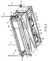
- FIG. 2 is a perspective view showing that the indoor unit is hung with four hanging bolts;
- FIG. 3 is a perspective view of the indoor unit;
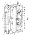
- FIG. 4 is a perspective view showing an inner structure of the indoor unit; and
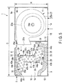
- FIG. 5 is a cross-sectional view of the indoor unit.
- an indoor unit 1 is fixed an attic of a building.
- the attic is ceiling space 4 defined by a beam 2 of the building and a ceiling 3.
- the indoor unit 1 is formed in the shape of a rectangular flat box having depth D, width W and thickness H.
- depth D is smaller than width W
- thickness H is sufficiently smaller than depth D and width W.
- the indoor unit 1 includes a housing 5 formed of metal.
- the housing 5 is an element forming an outer periphery of the indoor unit 1, and includes a top plate 6, a first side plate 7, a second side plate 8, a bottom plate 9, a front frame 10, a back plate 11 and a partition plate 12.
- the top plate 6 includes an upper plate portion 6a extending in a horizontal direction and a flange portion 6b bent downwards from a peripheral edge of the upper plate portion 6a.
- the first side plate 7 is located at an end portion of the top plate 6 in a width direction.
- the first side plate 7 includes an upper end portion fixed to the flange portion 6b of the top plate 6 by a plurality of screws, and extends downwards from the end portion of the top plate 6.
- the second side plate 8 is located at another end portion of the top plate 6 in the width direction.
- the second side plate 8 includes an upper end portion fixed to the flange portion 6b of the top plate 6 by a plurality of screws, and extends downwards from the above other end portion of the top plate 6.
- the first side plate 7 and the second side plate 8 are spaced from each other to face each other in the width direction of the indoor unit 1.
- the bottom plate 9 is fixed to the front frame 10 and the partition plate 12 in such a way as to extend between an end portion of the first side plate 7 and an end portion of the second side plate 8, thereby forming the bottom of the housing 5.
- the length of the bottom plate 9 in the depth direction of the housing 5 is substantially half depth D of the housing 5.
- a region of the bottom of the housing 5 which is other than the bottom plate 9 forms an elongate intake 14.
- the intake 14 faces an intake grille 15 provided in a ceiling 3.
- the front frame 10 is fixed to a front edge of the top plate 6, a front edge of the first side plate 7 and a front edge of the second side plate 8 by a plurality of screws.
- the front frame 10 forms an elongate outlet 16 at a front end of the housing 5.
- an outlet duct 17 is connected to the outlet 16.
- the outlet duct 17 is provided in the ceiling space 4, and also connected to an outlet grille (not shown) provided in the ceiling 3.
- the back plate 11 is detachably fixed to a rear edge of the top plate 6, a rear edge of the first side plate 7 and a rear edge of the second side plate 8 by a plurality of screws.
- the back plate 11 has a size determined in accordance with the intake 14. Therefore, after the back plate 11 is detached from the rear edge of the top plate 6, the read edge of the first side plate 7 and the rear edge of the second side plate 8, it can be fixed to the bottom of the housing 5 by a plurality of screws in such a way to cover the intake 14.
- a region surrounded by the rear edge of the top plate 6, the rear edge of the first side plate 7, the rear edge of the second side plate 8 and the rear edge of the back plate 11 functions as an intake.
- the partition plate 12 is raised along a side edge of the intake 14.
- a peripheral portion of the partition plate 12 is jointed to a lower surface of the top plate 6, an inner surface of the first side plate 7 and an inner surface of the second side plate 8.
- the partition plate 12 partitions the inside of the housing 5 into two chambers, i.e., a blowing chamber 18 and a heat exchange chamber 19. Furthermore, part of an inner surface of the first side plate 7 which is located in the heat exchange chamber 19 is covered by a first side-portion heat-insulating material 13a. Similarly, part of the second side plate 8 which is located in the heat exchange chamber 19 is covered by a second side-portion heat-insulating material 13b.
- the blowing chamber 18 includes the intake 14.
- a blower 21 is provided in the blowing chamber 18. As shown in FIG. 4 , the blower 21 comprises a fan motor 22 and a pair of fans 23a and 23b.
- the fan motor 22 includes two rotation shafts 24a and 24b which coaxially project from its both side surfaces, and to which the fans 23a and 23b are attached.
- the fans 23a and 23b are surrounded by fan cases 25a and 25b, respectively.
- the fan cases 25a and 25b include nozzle portions 26a and 26b which penetrate the partition plate 12.
- the nozzle portions 26a and 26b include blast openings 27a and 27b which communicate with the heat exchange chamber 19.
- the heat exchange chamber 19 includes the outlet 16 and a machine compartment 20 as shown in FIG. 2 .
- the machine compartment 20 contains a drain pump, a refrigerant distributor, etc., and is divided from the heat exchange chamber 19 by a machine-compartment partition plate 20a.
- a heat exchanger 28 and a drain pan 29 are provided in the heat exchange chamber 19.
- the heat exchanger 28 extends in the width direction of the indoor unit 1, and is located between the machine-compartment partition plate 20a and the second side-portion heat-insulating material 13b.
- an upper end portion of the heat exchanger 28 is pushed and put into contact with an upper-portion heat-insulating material 30.
- the upper-portion heat-insulating material 30 is located between the upper end portion of the heat exchanger 28 and the top plate 6.
- the first side-portion heat-insulating material 13a, the second side-portion heat-insulating material 13b and the upper-portion heat-insulating material 30 restricts transmission of heat generated in a refrigeration cycle operation of the heat exchanger 28 to the housing 5.
- the drain pan 29 is provided under the heat exchanger 28.
- the drain pan 29 is formed of a heat-insulating material such as foam polystyrene.
- the drain pan 29 supports the heat exchanger 28 from underneath, and receives drained water dropping from the heat exchanger 28.
- the housing 5, which contains the blower 21 and the heat exchanger 28, is hung from the beam 2 of the building, with for example, four hanging bolts 31 interposed between the housing 5 and the beam 2.
- four metallic hanging fittings 32 are fixed to the top plate 6 of the housing 5.
- the metallic hanging fittings 32 horizontally project in four directions from four corners of the top plate 6 toward four parts of the housing 5, respectively, and lower end portions of the hanging bolts 31 are coupled to the metallic hanging fittings 32, respectively.
- the heat exchanger 28 comprises a first heat exchange unit 35, a second heat exchange unit 36 and a third heat exchange unit 37.
- the first to third heat exchange units 35, 36 and 37 are examples of first to third heat exchange portions.
- the first to third heat exchange units 35, 36 and 37 are separate elements provided independent of each other, and are combined and formed in a predetermined three-dimensional shape.
- the first heat exchange unit 35 is provided in an upper region of the heat exchange chamber 19, and extends in a direction away from the blower 21 and also in the depth direction of the indoor unit 1.
- the first heat exchange unit 35 is slightly upwardly inclined to extend in the direction away from the blower 21.
- the second heat exchange unit 36 is provided in a bottom region of the heat exchange chamber 19, and is separated from the first heat exchange unit 35 in the thickness direction of the housing 5.
- the second heat exchange unit 36 also extends in a direction toward the blower 21 and in the depth direction of the indoor unit 1, and is slightly downwardly inclined to extend in the direction toward the blower 21.
- the third heat exchange unit 37 connects a rear end portion of the first heat exchange unit 35 and a front end portion of the second heat exchange unit 36 to each other.
- the third heat exchange unit 37 is raised in the heat exchange chamber 19 to face the blast openings 27a and 27b of the fan cases 25a and 25b and the partition plate 12.
- the heat exchanger 28 comprises: the third heat exchange unit 37 which is raised to face the blast openings 27a and 27b and the partition pate 12; the first heat exchange unit 35 which obliquely upwardly extends from an upper end portion of the third heat exchange unit 37 toward the outlet 16; and the second heat exchange unit 36 which obliquely downwardly extends from a lower end portion of the third heat exchange unit 37 toward the partition plate 12.
- the first to third heat exchange units 35, 36 and 37 are combined and continuously formed substantially in a Z-shape.
- the first to third heat exchange units 35, 36 and 37 each comprise a plurality of fins 38, plural heat transfer pipes 39 which a refrigerant will flow, a first end plate 40 and a second end plate 41.
- the fins 38 are each, for example, a rectangular plate formed of aluminum, and include a pair of linear long sides 43a and 43b and a pair of linear short sides 44a and 44b.
- the long sides 43a and 43b are parallel to each other.
- the short sides 44a and 44b are parallel to each other, and extend in such an oblique direction as to cross the long sides 43a and 43b.
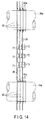
- the fins 38 include such plural engagement holes 45 as shown in FIG. 14 .
- the engagement holes 45 are formed by performing, for example, burring processing on the fins 38, and include cylindrical flange portions 45a raised from the fins 38.
- engagement holes 45 are arranged in four rows along the long sides 43a and 43b of the fins 38, and also in three rows along the short sides 44a and 44b of the fins 38. The direction along the long sides 43a and 43b can be translated into a step direction, and the direction along the short sides 44a and 44b can be translated into a row direction.
- fins 38 are arranged in a single row and at intervals in the width direction of the indoor unit 1. Distal ends of the flange portions 45a raised from the fins 38 are provided such that the distal end of the flange portion 45a raised from one of adjacent fins 38 is pushed and put into contact with the engagement hole 45 of the other fin 38 and also coaxially aligned with the engagement hole 45. Thus, between the adjacent fins 38, an air passage 46 is provided through which air flows.
- each of the fins 38 of the first to third heat exchange units 35, 36 and 37 includes a plurality of slits 71.
- the slits 71 are formed by cutting and raising part of the fins 38 which is located between engagement holes 45 arranged in the step direction, and raised portions 72 defining the slits 71 overhang into the air passage 46.
- the slits 71 extend in a direction where the engagement holes 45 are arranged in the step direction, such that between any adjacent engagement holes 45, three slits 45 are provided.
- the heat transfer pipes 39 are formed of, for example, copper pipes having an excellent thermal conductivity.
- Each of the heat transfer pipes 39 comprises two linear pipe portions 39a linearly which extend in the width direction of the indoor unit 1 and a bent pipe portion 39b which is bent and substantially U-shaped.
- the linear pipe portions 39a of the heat transfer pipes 39 continuously communicate with the engagement holes 45 of the fins 38.
- the linear pipe portions 39a are inserted into the engagement holes 45 of the fins 38, and their bores are then expanded by a rod-like jig, as a result of which the linear pipe portions 39a are firmly brought in intimate contact with the inner surfaces of the flange portions 45a.
- the heat transfer pipes 39 are united with the fins 38 such that heat transfer pipes 39 are arranged in two rows in the step direction and also in three rows in the row direction; and they are also thermally connected to the fins 38.
- the first and second end plates 40 and 41 are flat plates formed of, for example, hot-dip galvanized copper plates, and have shapes and sizes determined in accordance with the fins 38.
- the first end plate 40 includes a pair of linear long sides 47a and 47b and a pair of linear short sides 48a and 48b.
- the long sides 47a and 47b are parallel to each other.
- the short sides 48a and 48b are parallel to each other, and extend in such an oblique direction as to cross the long sides 47a and 47b.
- the long sides 47a and 47b of the first end plate 40 extend along the long sides 43a and 43b of the fins 38, and the short sides 48a and 48b of the first end plate 40 extend along the short sides 44a and 44b of the fins 38.
- the second end plate 41 includes a pair of linear long sides 50a and 50b and a pair of linear short sides 51a and 51b.
- the long sides 50a and 50b are parallel to each other.
- the short sides 51a and 51b are parallel to each other, and extend in such an oblique direction as to cross the long sides 50a and 50b.
- the long sides 50a and 50b of the second end plate 41 extend along the long sides 43a and 43b of the fins 38, and the short sides 48a and 48b of the second end plate 41 extend along the short sides 44a and 44b of the fins 38.
- the first end plate 40 is adjacent to one of outermost ones of the fins 38 in a direction in which the fins 38 are arranged. Open ends of the linear pipe portions 39a of the heat transfer pipes 39 penetrate the first end plate 40 to project to a side of the first end plate 40.
- the second end plate 41 is adjacent to the other outermost one of the fins 38 in the arrangement direction of the fins 38.
- the bent portions 39b of the heat transfer pipes 39 project to a side of the second end plate 41.
- fins 38 are arranged in a row between the first end plate 40 and the second end plate 41, and the linear pipe portions 39a of heat transfer pipes 39, which are arranged in four rows in the step direction and in three rows in the row direction, are provided to linearly extend between the first end plate 40 and the second end plate 41.
- flange portions 53a and 53b are formed integral with the long sides 47a and 47b of the first plate 40.
- the flange portions 53a and 53b are bent at a right angle to the first end plate 40 in a direction away from the fins 38.
- flange portions 54a and 54b are formed integral with the long sides 50a and 50b of the second end plate 41.
- the flange portions 54a and 54b are bent at a right angle to the second end plate 41 in a direction away from the fins 38.
- a pair of boss portions 55a and 55b are formed at the flange portion 54a, i.e., one of the flange portions of the second end plate 41, which forms the third heat exchange unit 37.
- the boss portions 55a and 55b project from a surface of the flange portion 54a, and are separated from each other in the longitudinal direction of the flange portion 54a.
- first to third heat exchange units 35, 36 and 37 are coupled to each other by first to first to fourth brackets 57a, 57b, 57c and 57d.
- the first to fourth brackets 57a, 57b, 57c and 57d are elements identical to each other, and each include a first fixture portion 58a and a second fixture portion 58b.
- the first fixture portion 58a and the second fixture portion 58b are formed in the shape of an elongate plate, and the first fixture portion 58a is longer than the second fixture portion 58b.
- the second fixture portion 58b extends from one of ends of the first fixture portion 58a in an oblique direction at, for example, a greater angle than a right angle to the first fixture portion 58a.
- the first to fourth brackets 57a, 57b, 57c and 57d are bent substantially in an L-shape.
- the first fixture portions 58a of the first to fourth brackets 57a, 57b, 57c and 57d include a plurality of through holes 59 and recess portions 60.
- the through holes 59 are spaced from each other in the longitudinal direction of the first fixture portions 58a, and each have such a size as to be engaged with any of the boss portions 55a and 55b formed at the flange portion 54a.
- the recess portions 60 are located at respective other ends of the first fixture portions 58a. Each of the recess portions 60 has such a size as to be engaged with any of the boss portions 55a and 55b formed at the flange portion 54a.
- the second fixture portions 58b, as well as the first fixture portions 58a include a plurality of through holes 59.
- the through holes 59 are spaced from each other in the longitudinal directions of the second fixture portions 58b.
- the first bracket 57a and the second bracket 57b couple the first to third heat exchange units 35, 36 and 37 to each other on a side where the first end plate 40 is located.
- the third bracket 57c and the fourth bracket 57d couple the first to third heat exchange units 35, 36 and 37 to each other on a side where the second end plate 41 is located.
- the first fixture portions 58a are stacked on flange portions 54a of the second end plate 41, which are included in the third heat exchange unit 37.
- the third bracket 57c is fixed to an upper portion of the flange portion 54a by a screw 62, with the recess portion 60 of its first fixture portion 58a engaged with the boss portion 55a.
- the screw 62 is screwed into the flange portion 54a through any of the through holes 59 formed in the first fixture portion 58a.
- the second fixture portion 58b of the third bracket 57c extends from the first fixture portion 58a to a location forward of the third heat exchange unit 37.
- the second fixture portion 58b of the third bracket 57c is fixed to the flange portion 54a of the second end plate 41, which is included in the first heat exchange unit 35, by a screw 62.
- the screw 62 is screwed into the flange portion 54a through any of the through holes 59 formed in the second fixture portion 58b.
- the fourth bracket 57d is fixed to a lower portion of the flange portion 54a by a screw 62, with the boss portion 55b engaged with any of the through holes 59 of the first fixture portion 58a.
- the screw 62 is screwed into the flange portion 54a through any of the through holes 59 of the first fixture portion 58a.
- the second fixture portion 58b of the fourth bracket 57d extends from the first fixture portion 58a to a location rearward of the third heat exchange unit 37.
- the second fixture portion 58b of the fourth bracket 57d is fixed to the flange portion 54a of the second end plate 41, which is included in the second heat exchange unit 36, by a screw 62.
- the screw 62 is screwed into the flange portion 54a through any of the through holes 59 formed in the second fixture portion 58b.
- the first bracket 57a extends in the same direction as the third bracket 57c and between the flange portion 53a of the first end plate 40, which is included in the first heat exchange unit 35 and the flange portion 53a of the first end plate 40, which is included in the third heat exchange unit 37.
- the first fixture portion 58a of the first bracket 57a is fixed to the flange portion 53a of the third heat exchange unit 37 by a screw 62.
- the second fixture portion 58b of the first bracket 57a is fixed to the flange portion 53a of the first heat exchange unit 35 by a screw 62.
- the second bracket 57b extends in the same direction as the fourth bracket 57d and between the flange portion 53a of the first end plate 40, which is included in the second heat exchange unit 36, and the flange portion 53a of the first end plate 40 which is included in the third heat exchange unit 37.
- the first fixture portion 58a of the second bracket 57b is fixed to the flange portion 53a of the third heat exchange unit 37 by a screw 62.
- the second fixture portion 58b of the second bracket 57b is fixed to the flange portion 53a of the second heat exchange unit 36 by a screw 62.
- the first to third heat exchange units 35, 36 and 37 which are formed independent of each other, are coupled to each other to be substantially Z-shaped, by the first to fourth brackets 57a, 57b, 57c and 57d.
- the short sides 44b of the fins 38 which are included in the first heat exchange unit 35, and the short sides 44a of the fins 38, which are included in the third heat exchange unit 37, are jointed to each other.
- open ends of the linear pipe portions 39a of the heat transfer pipes 39, which penetrate the first end plate 40, are connected to each other by a plurality of return bends 65.
- some return bends 65 extend between the first heat exchange unit 35 and the third heat exchange unit 37, and some return bends 65 extend between the second heat exchange unit 36 and the third heat exchange unit 37.
- the bent portions 39b of the heat transfer pipes 39 project from the second end plate 41 such that in each of the first to third heat exchange units 35, 36 and 37, bent portions 39b are arranged in two rows in the step direction and also in three rows in the row direction. Furthermore, the bent portions 39b are interposed between the flange portions 54a and 54b of the second end plate 41.
- the heat transfer pipes 39 and the return bends 65 are combined into a refrigerant passage which is bent in a meandering manner.
- the first heat exchange unit 35 and the second heat exchange unit 36 are identical elements, and have the same shape.
- the first heat exchange unit 35 and the second heat exchange unit 36 extend from the third heat exchange unit 37 such that they are inclined at the same angle.
- the third heat exchange unit 37 is shaped axisymmetrically with respect to the first heat exchange unit 35 and the second heat exchange unit 36.
- all the fins 38 of the first to third heat exchange units 35, 36 and 37 are made to function in the same manner.
- the bent portions 39 of the heat transfer pipes 39 are interposed between the second side-portion heat-insulating material 13b and the second end plates 41 of the first to third heat exchange units 35, 36 and 37.
- the flange portions 54a of the second end plates 41 overhang from the second end plate 41 toward the second side-portion heat-insulating material 13b to stop gaps between the second end plates 41 and the second side-portion heat-insulating material 13b.
- an end portion of the flange portion 54a of the third heat exchange unit 37 which is raised in the heat exchange chamber 19, extends toward an end portion of the flange portion 54a of the second heat exchange unit 36. It is therefore possible to reduce as much as possible a gap between adjacent flange portions 54a, which would cause air leak, and also to reduce the amount of air which leaks without thermal exchange.
- the fans 23a and 23b when the fans 23a and 23b are rotated by the fan motor 22, the fans 23a and 23b take air in the blowing chamber 18 in the axial direction, and discharge the air from the outer peripheral surfaces of the fans 23a and 23b toward the inner sides of the fan cases 25a and 25b.
- air in a compartment in the building is taken from the intake grille 15 of the ceiling 3 into the blowing chamber 18 through the intake 14 of the housing 5.
- the air taken in the blowing chamber 18 blows out from the blast openings 27a and 27b of the fan cases 25a and 25b toward the heat exchanger 28.
- the third heat exchange unit 37 of the heat exchanger 28 is raised in the heat exchange chamber 19 in such a way as to face the blast openings 27a and 27b, as a result of which much of air which blows out from the blast openings 27a and 27b into the heat exchange chamber 19 passes between the fins 38 of the third heat exchange unit 37.
- the remainder of the air blowing into the heat exchange chamber 19 passes between the fins 38 of the first heat exchange unit 35, which extend from the upper end portion of the third heat exchange unit 37 toward the outlet 16 and also between the fins 38 of the second heat exchange unit 36, which extend from the lower end portion of the third heat exchange unit 37 toward the partition plate 12.
- the heat exchanger 28 changes the air blowing out from the blast openings 27a and 27b into a heat exchange air such as chilled or warm air because of a heat exchange between the above air and the refrigerant which flows through the heat transfer pipes 39.
- the heat exchange air is sent from the outlet 16 into the compartment through the outlet duct 17.
- the heat exchanger 28 is formed by combining and forming the first to third heat exchange units 35, 36 and 37 substantially in a Z-shape, and is bent in a three-dimensional shape.
- the dimension of the heat exchanger 28 along the depth direction of the heat exchange chamber 19 can be shortened, as compared with the case where a conventional linear heat exchanger is inclined in the heat exchange chamber.
- the heat exchange chamber 19 can be made to have a smaller depth dimension, and the housing 5 of the indoor unit 1 can be made more compact.
- the thermal capacity of the heat exchanger 28 can be sufficiently ensured. Therefore, a heat exchanger 28 made to have a great thermal capacity can be provided in a small heat exchange chamber 19, and an indoor unit 1 having an excellent heat exchange function can be provided.
- the housing 5 is made compact, it can be made lighter. Thus, the workability of installing the indoor unit 1 in the ceiling space 4 is improved. Furthermore, since the housing 5 is compact, it is possible to reduce the manufacturing cost of the housing 5, and obtain an inexpensive indoor unit 1.
- the third heat exchange unit 37 is raised in the heat exchange chamber 19
- the difference between the distance from the open ends of the blast openings 27a and 27b to the front end of the first heat exchange unit 35 and that from the open ends of the blast openings 27a and 27b to the rear end of the second heat exchange unit 37 is reduced, as compared with the case where the conventional linear heat exchanger is inclined in the heat exchange chamber. It is therefore possible to make air blow substantially uniformly to the heat exchanger, and obtain an excellent heat exchange function.
- the first heat exchange unit 35 is upwardly inclined from the upper end of the third heat exchange unit 37 toward the outlet 16
- the second heat exchange unit 36 is downwardly inclined from the lower end of the third heat exchange unit 37 toward the partition plate 12.
- a gap which would air leak is not made in the boundary between the first heat exchange unit 35 and the third heat exchange unit 37 or in that between the second heat exchange unit 36 and the third heat exchange unit 37.
- all the fins 38 of the first to third heat exchange units 35, 36 and 37 are made identical to each other, and the number of components of the heat exchanger 28 can be reduced. As a result, the cost of the heat exchanger 28 can be reduced, and it is also advantageous in achievement of an inexpensive indoor unit 1.
- the third heat exchange unit 37 is raised in the heat exchange chamber 19, for example, it may be forwardly inclined such that its upper end portion is closer to the outlet 16 than its lower end portion, or it may be backwardly inclined such that its lower end portion is closer to the outlet 16 than its upper end portion.
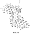
- FIG. 17 discloses the second embodiment.
- the second embodiment is different from the first embodiment in matter regarding the arrangement of the linear pipe portions 39a of the heat transfer pipes 39.
- the second embodiment is the same as the first embodiment. Therefore, with respect to the second embodiment, structural elements identical to those in the first embodiment will be denoted by the same reference numbers as in the first embodiment, respectively, and their detailed explanations will be omitted.
- linear pipe portions 39a of heat transfer pipes 39 are arranged at predetermined pitch P1 in the row direction and arranged in at predetermined pitch P2 in the step direction.
- Pitch P2 is set greater than pitch P1.
- the linear pipe portions 39a of three heat transfer pipes 39 of the first heat exchange unit 35 are adjacent to the linear pipe portions 39a of three heat transfer pipes 39 of the third heat exchange unit 37, respectively.
- Pitch P3 between the linear pipe portions 39a of heat transfer pipes 39 located adjacent to each other with respect to line S1 extending in the above boundary is set equal to pitch P1 described above.
- pitch P4 between the linear pipe portions 39a of heat transfer pipes 39 located adjacent to each other in the step direction with respect to line S1 is set equal to pitch P2 described above.
- the linear pipe portions 39a of three heat transfer pipes 39 of the second heat exchange unit 36 are adjacent to the linear pipe portions 39a of three heat transfer pipes 39 of the third heat exchange unit 37, respectively.
- Pitch P5 between the linear pipe portions 39a of heat transfer pipes 39 located adjacent to each other with respect to line S2 extending in the above boundary is set equal to pitch P1 described above.
- pitch P6 between the linear pipe portions 39a of heat transfer pipes 39 located adjacent to each other in the step direction with respect to line S2 extending in the above boundary is set equal to pitch P2 described above.
- the first to third heat exchange units 35, 36 and 37 are combined together such that pitches P3 and P4 between the linear pipe portions 39a of heat transfer pipes 39 located adjacent to each other with respect to the boundary between the first heat exchange unit 35 and the third heat exchange unit 37 and pitches P5 and P6 between the linear pipe portions 39a of heat transfer pipes 39 located adjacent to each other with the boundary between the second heat exchange unit 36 and the third heat exchange unit 37 are equal to pitches P1 and P2 of the liner pipe portions 39a of the heat transfer pipes 39 which are set in each of the first to third heat exchange units 35, 36 and 37.
- FIG. 18 shows the third embodiment.
- the third embodiment is different from the first embodiment in matter regarding the arrangement of the fins 38 of the first to third heat exchange units 35, 36 and 37.
- the third embodiment is the same as the first embodiment. Therefore, with respect to the third embodiment, structural elements identical to those in the first embodiment will be denoted by the same reference numbers as in the first embodiment, respectively, and their detailed explanations will be omitted.
- fin pitch FP1 between the fins 38 of the third heat exchange unit 37 is set smaller than fin pitch FP2 between the fins 38 of the first heat exchange unit 35 and fin pitch FP3 between the fins 38 of the second heat exchange unit 36.
- fin pitches FP2 and FP3 are greater than FP1.
- fin pitch FP1 is smaller than fin pitches FP2 and FP3, thus increasing the airflow resistance of air passing between the fins 38 of the third heat exchange unit 37.
- some of air sent from the blower 21 toward the third heat exchange unit 37 flows toward the first heat exchange unit 35, which extends from the upper end of the third heat exchange unit 37 toward the outlet 16 and the second heat exchange unit 36, which extends from the lower end of the third heat exchange unit 37 toward the partition plate 12.
- FIG. 19 shows the fourth embodiment.
- the fourth embodiment is different from the first embodiment regarding the structures of the first heat exchange unit 35 and the second heat exchange unit 36.
- the fourth embodiment is the same as the first embodiment. Therefore, with respect to the fourth embodiment, structural elements identical to those in the first embodiment will be denoted by the same reference numbers as in the first embodiment, respectively, and their detailed explanations will be omitted.
- the first heat exchange unit 35 and the second heat exchange unit 36 include a plurality of fins 70 to which the linear pipe portions 39a of the heat transfer pipes 39 are thermally connected.
- the fins 70 are, for example, flat rectangular plates formed of aluminum.
- the fins 70 have the same outer shapes as the fins 38 in the first embodiment, but do not include such slits 71 and raised portions 72 as shown in FIG. 14 with respect to the
- the fins 70 include engagement holes 45 which penetrate the liner pipe portions 39a of the heat transfer pipes 39.
- the engagement holes 45 are formed by performing, for example, burring processing on the fins 70, and include cylindrical flange portions 45a raised from the fins 70.
- engagement holes 45 are arranged in four rows in the step direction and in three rows in the row direction.
- the fins 70 are arranged at intervals in a single row in the axial direction of each of the linear pipe portions 39a of the heat transfer pipes 39.
- the distal ends of the flange portions 45a raised from adjacent fins 70 are brought into contact with and coaxial with the engagement holes 45 of the adjacent fins 70.
- air passages 46 in which air will flow are formed.
- the fins 70 of the first and second heat exchange units 35 and 36 are flat, whereas the fins 38 of the third heat exchange unit 37 include a plurality of raised portions 72 defining the slits 71.
- the raised portions 72 project into the air passages 46 between the adjacent fins 38 to disturb the flow of air passing through the air passage 46.
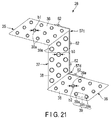
- FIGS. 20 and 21 disclose the fifth embodiment.
- the fifth embodiment is different from the first embodiment in the structure of the third heat exchange unit 37.
- the fifth embodiment is the same as the first embodiment. Therefore, with respect to the fourth embodiment, structural elements identical to those in the first embodiment will be denoted by the same reference numbers as in the first embodiment, respectively, and their detailed explanations will be omitted.
- inside diameter b3 of the linear pipe portions 39a of heat transfer pipes 39 included in the third heat exchange unit 37 is greater than inside diameter b1 of the linear pipe portions 39a of heat transfer pipes 39 included in the first heat exchange unit 35 and inside diameter b2 of the linear pipe portions 39a of the heat transfer pipes 39 included in the second heat exchange unit 36.
- Inside diameter b1 of the linear pipe portions 39a in the first heat exchange unit 35 is equal to inside diameter b2 of the linear pipe portions 39a in the second heat exchange unit 36.
- the third heat exchange unit 37 of the heat exchanger 28, as shown in FIG. 20 faces the blast openings 27a and 27b of the blower 21 in the heat exchange chamber 19, as a result of which much of air sent from the blower 21 passes between the fins 38 of the third heat exchange unit 37.
- the flow rate of refrigerant flowing in the third heat exchange unit 37 increases, since inside diameter b3 of the linear pipe portions 39a of the heat transfer pipes 39 in the third heat exchange unit 37, which the refrigerant will flow, is greater than inside diameter b1 of the linear pipe portions 39a of the heat transfer pipes 39 in the first heat exchange unit 35 and inside diameter b2 of the linear pipe portions 39a of the heat transfer pipes 39 in the second heat exchange unit 36.
- the thermal capacity of the third heat exchange unit 37, on which air sent from the blower 21 easily blows, can be increased, and the air and the refrigerant can exchange heat with each other in a balanced manner. Therefore, the above structure is advantageous in improvement of the heat exchange function of the heat exchanger 28.
- FIG. 22 discloses the sixth embodiment.
- the sixth embodiment is different from the first embodiment regarding the structure of the heat exchanger 28.
- the sixth embodiment is the same as the first embodiment. Therefore, with respect to the sixth embodiment, structural elements identical to those in the first embodiment will be denoted by the same reference numbers as in the first embodiment, respectively, and their detailed explanations will be omitted.
- linear pipe portions 39a of heat transfer pipes 39 are combined with fins 38, while they are arranged in four rows in the step direction and in two rows in the row directions.
- the third heat exchange unit 37 linear pipe portions 39a of heat transfer pipes 39 are combined with fins 38, while they are arranged in four rows in the step direction and in three rows in the row direction.
- the number of heat transfer pipes 39 in the third heat exchange unit 37 is larger than those of the first heat exchange unit 35 and the second heat exchange unit 36.
- the third heat exchange unit 37 of the heat exchanger 28 face the blast openings 27a and 27b of the blower 21 in the heat exchange chamber 19, as a result of which much of air sent from the blower 21 passes between the fins 38 of the third heat exchange unit 37.
- the flow rate of refrigerant flowing in the third heat exchange unit 37 increases, since the number of the heat transfer pipes 39 in the third heat exchange unit 37, which the refrigerant will flow, is larger than those of the first heat exchange unit 35 and the second heat exchange unit 36.
- the thermal capacity of the heat exchange unit 37 on, which air sent from the blower 21 easily flows, can be increased, and the air and the refrigerant can exchange heat with each other in a balanced manner. Therefore, the above structure is advantageous in improvement of the heat exchange function of the heat exchanger 28.
- FIG. 23 shows the seventh embodiment.
- the seventh embodiment is different from the first embodiment regarding the structure of the heat exchanger 28.
- the seventh embodiment is the same as the first embodiment. Therefore, with respect to the seventh embodiment, structural elements identical to those in the first embodiment will be denoted by the same reference numbers as in the first embodiment, respectively, and their detailed explanations will be omitted.
- the heat exchanger 28 is a monolithic structure in which a first heat exchange unit 81, a second heat exchange unit 82 and a third heat exchange unit 83 are continuous with each other.
- the first heat exchange unit 81 is provided in an upper region of the heat exchange chamber 19, and extends in a direction away from the blower 21 and in the depth direction of the indoor unit 1.
- the first heat exchange unit 81 is slightly inclined upward to extend in the direction away from the blower 21.
- the second heat exchange unit 82 is provided in a bottom region of the heat exchange chamber 19, and separated from the first heat exchange unit 81 in the thickness direction of the housing 5. Also, the second heat exchange unit 82 extends toward the blower 21 in the depth direction of the indoor unit 1, and is slightly inclined downward to extend toward the blower 21.
- the third heat exchange unit 83 connects the rear end of the first heat exchange unit 81 and the front end of the second heat exchange unit 82 to each other.
- the third heat exchange unit 83 is raised in the heat exchange chamber 19 in such a way as to face the blast openings 27a and 27b of the blower 21 and the partition plate 12.
- the heat exchanger 28 comprises: the third heat exchange unit 83, which is raised to face the blast openings 27a and 27b; the first heat exchange unit 81, which obliquely upwards extends from the upper end of the third heat exchange unit 83 toward the outlet 16; and the second heat exchange unit 82, which obliquely downwards extends from the lower end of the third heat exchange unit 83 toward the partition plate 12. Therefore, in the seventh embodiment, the heat exchanger 28 is substantially Z-shaped as seen in side view of the indoor unit 1.
- the heat exchanger 28 comprises a plurality of fins 87 and the heat transfer pipes 39 in which a refrigerant will flow.
- the fins 87 include a first flat portion 87a which forms the first heat exchange unit 81, a second flat plate portion 87b which forms the second heat exchange unit 82, and a third flat plate portion 87c which forms the third heat exchange unit 83.
- the first to third flat plate portions 87a, 87b and 87c are formed continuous with each other to form a single body and in a shape substantially similar to a Z-shape.
- the fins 87 having such a shape are arranged at intervals and in a row in the width direction of the indoor unit 1.
- the heat transfer pipes 39 each comprise two linear pipe portions 39a which linearly extend in the width direction of the indoor unit 1 and bent portions 39b which are substantially U-shaped, as in the first embodiment.
- the linear pipe portions 39a of the heat transfer pipes 39 penetrate the first to third flat plate portions 87a, 87b and 87c of the fins 87.
- the heat transfer pipes 39 are formed integral with the fins 87 and thermally connected thereto, while they are arranged in two rows in the step direction and in three rows in the row direction with respect to the first to third flat plate portions 87a, 87b and 87c.
- the fins 87 are formed continuous with each other in the first to third heat exchange units 81, 82 and 83 substantially in a Z-shape.
- the first to third heat exchange units 81, 82 and 83 of the heat exchanger 28 are provided continuous with each other to form a monolithic structure, and the heat exchanger 28 is provided as a monolithic element.
- the first to third heat exchange units 81, 82 and 83 do not need to be coupled with each other by a plurality of brackets; i.e., specific brackets can be omitted. Therefore, the number of components of the heat exchanger 28 can be reduced, thus improving the workability in assembling of the heat exchanger 28, and also reducing the cost of the heat exchanger 28.
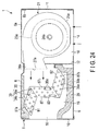
- FIGS. 24 and 25 disclose the eighth embodiment.
- the procedure in which a heat exchanger 28 is manufactured as a monolithic structure is concretely provided.
- the structure of the heat exchanger 28 is basically the same as that of the seventh embodiment.
- the heat exchanger 28 is a monolithic structure comprising the first heat exchange unit 81, the second heat exchange unit 82 and the third heat exchange unit 83, and is formed such that those units are continuous with each other and formed substantially in a Z-shape as seen in side view of the indoor unit 1.
- the fins 87 which are included in the heat exchanger 28, comprise first to third flat plate portions 87a, 87b and 87c.
- the first to third flat plate portions 87a, 87b and 87c are formed integral with each other and continuous with each other substantially in a Z-shape.
- the first to third flat plate portions 87a, 87b and 87c each include a pair of linear long sides 91a and 91b and a pair of linear short sides 92a and 92b.
- the long sides 91a and 91b are parallel to each other.
- the short sides 92a and 92b are parallel to each other, and extend in such an oblique direction as to cross the long sides 91a and 91b.
- the heat transfer pipes 39 of the heat exchanger 28 are formed integral with the fins 87 and thermally connected to the fins 87, such that they are arranged in two rows in the step direction and three rows in the row direction with respect to the first to third flat plate portions 87a, 87b and 87c.
- FIG. 25 shows linear plate-like fin bases 93 provided as bases of the fins 87.
- the fin bases 93 comprise the first to third flat plate portions 87a, 87b and 87c, a first notch 94 which is V-shaped and located between the first flat plate portion 87a and the third flat plate portion 87c, and a second notch 95 which is V-shaped and located between the second flat plate portion 87b and the third flat plate portion 87c.
- the first to third flat plate portions 87a, 87b and 87c and the first and second notches 94 and 95 are arranged in a straight line.
- the first notch 94 is defined by the short side 92b of the first flat plate portion 87a and the short side 92a of the third flat plate portion 87c.
- a first to-be-bent portion 96a is formed.
- the first to-be-bent portion 96a connects the first flat plate portion 87a and the third flat plate portion 87c to each other such that they are provided integral with each other.
- the second notch 95 is defined by the short side 92a of the second flat plate portion 87b and the short sides 92b of the third flat plate portion 87c.
- a second to-be-bent portion 96b is formed.
- the second to-be-bent portion 96b connects the second flat plate portion 87b and the third flat plate portion 87c to each other such that they are provided integral with each other.
- the first notch 94 and the second notch 95 are open in opposite directions.
- the linear pipe portions 39a of the heat transfer pipes 39 are inserted in a plurality of engagement holes 97 provided in the first to third flat plate portions 87a, 87b and 87c of the bases 93. After the linear pipe portions 39a of the heat transfer pipes 39 are inserted into the engagement holes 97 of the first to third flat plate portions 87a, 87b and 87c, they are forcibly expanded by a rod-like jig such that their bores are increased, as in the first embodiment, whereby they are fixed to the first to third flat plate portions 87a, 87b and 87c.
- the heat transfer pipes 39 penetrate the fin bases 93 such that in each of the first to third flat plate portions 87a, 87b and 87c, they are arranged in two rows in the step direction and in three rows in the row direction, thereby forming along with the fin bases 93, a fin assembly 98.
- the first to-be-bent portion 96a and the second to-be-bent portion 96b of the fin bases 93 are forcibly bent in directions where the first notch 94 and the second notch 95 are closed.
- the short side 92b of the first flat plate portion 87a is brought into contact with the short side 92a of the third flat plate portion 87c
- the short side 92a of the second flat plate portion 87b is brought into contact with the short side 92b of the third flat plate portion 87c. Therefore, the first to third flat plate portions 87a, 87b and 87c are bent such that they are formed continuous with each other substantially in a Z-shape, thereby obtaining a heat exchanger 28 which is substantially continuously Z-shaped.
- the fin bases 93 provided as the bases of the fins 87 are linearly plate-like before the first to-be-bent portion 96a and the second to-be-bent portion 96b are bent.
- this cutting can be improved, thus also improving yields.
Landscapes
- Engineering & Computer Science (AREA)
- Chemical & Material Sciences (AREA)
- Combustion & Propulsion (AREA)
- Mechanical Engineering (AREA)
- General Engineering & Computer Science (AREA)
- Physics & Mathematics (AREA)
- Thermal Sciences (AREA)
- Air Filters, Heat-Exchange Apparatuses, And Housings Of Air-Conditioning Units (AREA)
- Heat-Exchange Devices With Radiators And Conduit Assemblies (AREA)
Abstract
Description
- Embodiments described herein relate generally to an air conditioner including an indoor unit which is, for example, hung from a ceiling, and also to a heat exchanger.
- In an air conditioner provided with an indoor unit which is hung from a beam provided an attic, the indoor unit is internally partitioned into a heat exchange chamber and a blowing chamber by a partition plate. In the heat exchange chamber, a heat exchanger is provided, and in the blowing chamber, a blower which sends air to the heat exchanger is provided.
- The heat exchanger comprises a plurality of heat transfer pipes in which a refrigerant will flow and a plurality of fins thermally connected to the heat transfer pipes, and is formed in the shape of a straight, flat plate as a whole. Also, the heat exchanger is provided in the heat exchange chamber in such a way as to be greatly frontward inclined with respect to the blower, in order that the heat exchanger efficiently receive air sent from the blower, and the indoor unit be made to have the smallest possible thickness.
- Patent Literature 1:
JP 2006-343043 A - In a conventional air conditioner, a heat exchanger formed in the shape of a straight, flat plate is inclined in a heat exchange chamber. Inevitably, much wasted space is provided in the heat exchange chamber, and an indoor unit is made to have a greater depth. In particular, it should be noted that the outside dimensions of the heat exchanger increases in proportion to the thermal capacity thereof, and thus the larger the thermal capacity of the heat exchanger, the larger the installation space which needs to be provided in the heat exchange chamber. Therefore, the indoor unit cannot be made more compact.
- In addition, the distance between the blower and a front end portion of the heat exchanger is greatly different from that between the blower and a rear end portion of the heat exchanger. Thus, the amount of air passing through the heat exchanger easily varies from one location in the heat exchanger to another. Therefore, the heat exchanger is susceptible to improvement in order that it be made to sufficiently fulfill its function.
- An air conditioner according to an embodiment includes a housing provided with a heat exchange chamber and a blowing chamber, a heat exchanger provided in the heat exchange chamber to perform heat exchange between a refrigerant and air, and a blower provided in the blowing chamber to send air to the heat exchanger. The heat exchanger includes a first heat exchange unit extending in a direction away from the blower, a second heat exchange unit separated from the first heat exchange unit in the thickness direction of the housing, and extending toward the blower, and a third heat exchange unit connecting the first heat exchange unit and the second heat exchange unit to each other.
-
-
FIG. 1 is a side view showing that in a first embodiment, an indoor unit of an air conditioner is installed an attic. -
FIG. 2 is a perspective view showing that the indoor unit is hung by four hanging bolts. -
FIG. 3 is a perspective view showing the indoor unit of the air conditioner as seen from behind the indoor unit. -
FIG. 4 is a perspective view showing the indoor unit of the air conditioner as seen from below the indoor unit. -
FIG. 5 is a cross-sectional view of the indoor unit of the air conditioner. -
FIG. 6 is a perspective view of a heat exchanger to be provided in a heat exchange chamber. -
FIG. 7 is a side view showing the heat exchanger as seen in a direction indicated by arrow F7 inFIG. 6 . -
FIG. 8 is a side view showing the heat exchanger as seen in a direction indicated by arrow F8 inFIG. 6 . -
FIG. 9 is a perspective view showing the heat exchanger, which is reverse to that of the heat exchanger as shown inFIG. 6 . -
FIG. 10 is a perspective enlarged view of part indicated by F10 inFIG. 6 . -
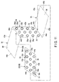
FIG. 11 is side view showing a relationship between first to third heat exchange units. -
FIG. 12 is a perspective view showing the heat exchanger in the case where it is provided in the heat exchange chamber. -
FIG. 13 is a side view of fins, which shows the shapes of slits. -
FIG. 14 is a cross-sectional view taken along line F14-F14 inFIG. 13 . -
FIG. 15 is an enlarged side view of the fins, which shows raised portions defining the slits. -
FIG. 16 is a cross-sectional view taken along line F16-F16 inFIG. 15 . -
FIG. 17 is a side view of a heat exchanger according to a second embodiment, which shows arrangement of heat transfer pipes of heat exchange units. -
FIG. 18 is a perspective view of a heat exchanger according to a third embodiment. -
FIG. 19 is a cross-sectional view showing a positional relationship between fins and heat transfer pipes in a fourth embodiment. -
FIG. 20 is a cross-sectional view of an indoor unit according to a fifth embodiment. -
FIG. 21 is a cross-sectional view of a heat exchanger according to the fifth embodiment. -
FIG. 22 is a cross-sectional view of an indoor unit according to a sixth embodiment. -
FIG. 23 is a cross-sectional view of an indoor unit according to a seventh embodiment. -
FIG. 24 is a cross-sectional view of an indoor unit according to an eighth embodiment. -
FIG. 25 is a cross-sectional view showing a procedure in which a heat exchanger is manufactured, with a fin assembly bent. - The first embodiment will be described with reference to
FIGS. 1 to 16 . -
FIG. 1 is a side view schematically showing an indoor unit of an air conditioner, which is fixed an attic;FIG. 2 is a perspective view showing that the indoor unit is hung with four hanging bolts;FIG. 3 is a perspective view of the indoor unit;FIG. 4 is a perspective view showing an inner structure of the indoor unit; andFIG. 5 is a cross-sectional view of the indoor unit. - As shown in
FIG. 1 , for example, anindoor unit 1 is fixed an attic of a building. In the first embodiment, the attic isceiling space 4 defined by abeam 2 of the building and aceiling 3. - As shown in
FIG. 3 , theindoor unit 1 is formed in the shape of a rectangular flat box having depth D, width W and thickness H. In theindoor unit 1, depth D is smaller than width W, and thickness H is sufficiently smaller than depth D and width W. - The
indoor unit 1 includes ahousing 5 formed of metal. Thehousing 5 is an element forming an outer periphery of theindoor unit 1, and includes atop plate 6, afirst side plate 7, asecond side plate 8, abottom plate 9, afront frame 10, aback plate 11 and apartition plate 12. - The
top plate 6 includes anupper plate portion 6a extending in a horizontal direction and aflange portion 6b bent downwards from a peripheral edge of theupper plate portion 6a. - The
first side plate 7 is located at an end portion of thetop plate 6 in a width direction. Thefirst side plate 7 includes an upper end portion fixed to theflange portion 6b of thetop plate 6 by a plurality of screws, and extends downwards from the end portion of thetop plate 6. Thesecond side plate 8 is located at another end portion of thetop plate 6 in the width direction. Thesecond side plate 8 includes an upper end portion fixed to theflange portion 6b of thetop plate 6 by a plurality of screws, and extends downwards from the above other end portion of thetop plate 6. Thus, thefirst side plate 7 and thesecond side plate 8 are spaced from each other to face each other in the width direction of theindoor unit 1. - The
bottom plate 9 is fixed to thefront frame 10 and thepartition plate 12 in such a way as to extend between an end portion of thefirst side plate 7 and an end portion of thesecond side plate 8, thereby forming the bottom of thehousing 5. The length of thebottom plate 9 in the depth direction of thehousing 5 is substantially half depth D of thehousing 5. A region of the bottom of thehousing 5 which is other than thebottom plate 9 forms anelongate intake 14. Theintake 14 faces anintake grille 15 provided in aceiling 3. Thefront frame 10 is fixed to a front edge of thetop plate 6, a front edge of thefirst side plate 7 and a front edge of thesecond side plate 8 by a plurality of screws. Thefront frame 10 forms anelongate outlet 16 at a front end of thehousing 5. As shown inFIG. 1 , anoutlet duct 17 is connected to theoutlet 16. Theoutlet duct 17 is provided in theceiling space 4, and also connected to an outlet grille (not shown) provided in theceiling 3. - The
back plate 11 is detachably fixed to a rear edge of thetop plate 6, a rear edge of thefirst side plate 7 and a rear edge of thesecond side plate 8 by a plurality of screws. Theback plate 11 has a size determined in accordance with theintake 14. Therefore, after theback plate 11 is detached from the rear edge of thetop plate 6, the read edge of thefirst side plate 7 and the rear edge of thesecond side plate 8, it can be fixed to the bottom of thehousing 5 by a plurality of screws in such a way to cover theintake 14. When theback plate 11 is fixed to the bottom of thehousing 5, a region surrounded by the rear edge of thetop plate 6, the rear edge of thefirst side plate 7, the rear edge of thesecond side plate 8 and the rear edge of theback plate 11 functions as an intake. - As shown in
FIGS. 4 and5 , thepartition plate 12 is raised along a side edge of theintake 14. A peripheral portion of thepartition plate 12 is jointed to a lower surface of thetop plate 6, an inner surface of thefirst side plate 7 and an inner surface of thesecond side plate 8. Thepartition plate 12 partitions the inside of thehousing 5 into two chambers, i.e., a blowingchamber 18 and aheat exchange chamber 19. Furthermore, part of an inner surface of thefirst side plate 7 which is located in theheat exchange chamber 19 is covered by a first side-portion heat-insulatingmaterial 13a. Similarly, part of thesecond side plate 8 which is located in theheat exchange chamber 19 is covered by a second side-portion heat-insulatingmaterial 13b. - The blowing
chamber 18 includes theintake 14. Ablower 21 is provided in the blowingchamber 18. As shown inFIG. 4 , theblower 21 comprises afan motor 22 and a pair offans - The
fan motor 22 includes tworotation shafts fans fans fan cases fan cases nozzle portions partition plate 12. Thenozzle portions blast openings heat exchange chamber 19. - The
heat exchange chamber 19 includes theoutlet 16 and amachine compartment 20 as shown inFIG. 2 . Themachine compartment 20 contains a drain pump, a refrigerant distributor, etc., and is divided from theheat exchange chamber 19 by a machine-compartment partition plate 20a. - As shown in
FIG. 5 , aheat exchanger 28 and adrain pan 29 are provided in theheat exchange chamber 19. Theheat exchanger 28 extends in the width direction of theindoor unit 1, and is located between the machine-compartment partition plate 20a and the second side-portion heat-insulatingmaterial 13b. - Furthermore, an upper end portion of the
heat exchanger 28 is pushed and put into contact with an upper-portion heat-insulatingmaterial 30. The upper-portion heat-insulatingmaterial 30 is located between the upper end portion of theheat exchanger 28 and thetop plate 6. The first side-portion heat-insulatingmaterial 13a, the second side-portion heat-insulatingmaterial 13b and the upper-portion heat-insulatingmaterial 30 restricts transmission of heat generated in a refrigeration cycle operation of theheat exchanger 28 to thehousing 5. - The
drain pan 29 is provided under theheat exchanger 28. Thedrain pan 29 is formed of a heat-insulating material such as foam polystyrene. Thedrain pan 29 supports theheat exchanger 28 from underneath, and receives drained water dropping from theheat exchanger 28. - As shown in
FIG. 2 , thehousing 5, which contains theblower 21 and theheat exchanger 28, is hung from thebeam 2 of the building, with for example, four hangingbolts 31 interposed between thehousing 5 and thebeam 2. To be more specific, fourmetallic hanging fittings 32 are fixed to thetop plate 6 of thehousing 5. Themetallic hanging fittings 32 horizontally project in four directions from four corners of thetop plate 6 toward four parts of thehousing 5, respectively, and lower end portions of the hangingbolts 31 are coupled to themetallic hanging fittings 32, respectively. - As shown in
FIGS. 5 to 9 , theheat exchanger 28 according to the first embodiment comprises a firstheat exchange unit 35, a secondheat exchange unit 36 and a thirdheat exchange unit 37. The first to thirdheat exchange units heat exchange units - More specifically, the first
heat exchange unit 35 is provided in an upper region of theheat exchange chamber 19, and extends in a direction away from theblower 21 and also in the depth direction of theindoor unit 1. The firstheat exchange unit 35 is slightly upwardly inclined to extend in the direction away from theblower 21. - The second
heat exchange unit 36 is provided in a bottom region of theheat exchange chamber 19, and is separated from the firstheat exchange unit 35 in the thickness direction of thehousing 5. The secondheat exchange unit 36 also extends in a direction toward theblower 21 and in the depth direction of theindoor unit 1, and is slightly downwardly inclined to extend in the direction toward theblower 21. - The third
heat exchange unit 37 connects a rear end portion of the firstheat exchange unit 35 and a front end portion of the secondheat exchange unit 36 to each other. The thirdheat exchange unit 37 is raised in theheat exchange chamber 19 to face theblast openings fan cases partition plate 12. - In other words, the
heat exchanger 28 comprises: the thirdheat exchange unit 37 which is raised to face theblast openings partition pate 12; the firstheat exchange unit 35 which obliquely upwardly extends from an upper end portion of the thirdheat exchange unit 37 toward theoutlet 16; and the secondheat exchange unit 36 which obliquely downwardly extends from a lower end portion of the thirdheat exchange unit 37 toward thepartition plate 12. - Therefore, in the first embodiment, as seen in side view of the
indoor unit 1, the first to thirdheat exchange units - As shown in
FIGS. 6 to 9 , the first to thirdheat exchange units fins 38, pluralheat transfer pipes 39 which a refrigerant will flow, afirst end plate 40 and asecond end plate 41. - The
fins 38 are each, for example, a rectangular plate formed of aluminum, and include a pair of linearlong sides short sides long sides short sides long sides - The
fins 38 include such plural engagement holes 45 as shown inFIG. 14 . The engagement holes 45 are formed by performing, for example, burring processing on thefins 38, and includecylindrical flange portions 45a raised from thefins 38. As shown inFIG. 5 , for example, engagement holes 45 are arranged in four rows along thelong sides fins 38, and also in three rows along theshort sides fins 38. The direction along thelong sides short sides - Furthermore,
fins 38 are arranged in a single row and at intervals in the width direction of theindoor unit 1. Distal ends of theflange portions 45a raised from thefins 38 are provided such that the distal end of theflange portion 45a raised from one ofadjacent fins 38 is pushed and put into contact with theengagement hole 45 of theother fin 38 and also coaxially aligned with theengagement hole 45. Thus, between theadjacent fins 38, anair passage 46 is provided through which air flows. - As shown in
FIGS. 13 to 16 , each of thefins 38 of the first to thirdheat exchange units slits 71. Theslits 71 are formed by cutting and raising part of thefins 38 which is located between engagement holes 45 arranged in the step direction, and raisedportions 72 defining theslits 71 overhang into theair passage 46. Theslits 71 extend in a direction where the engagement holes 45 are arranged in the step direction, such that between any adjacent engagement holes 45, threeslits 45 are provided. By virtue of provision of theslits 71, the heat transfer area of thefins 38 is increased, and the heat exchange function of theheat exchanger 28 is improved. - The
heat transfer pipes 39 are formed of, for example, copper pipes having an excellent thermal conductivity. Each of theheat transfer pipes 39 comprises twolinear pipe portions 39a linearly which extend in the width direction of theindoor unit 1 and abent pipe portion 39b which is bent and substantially U-shaped. Thelinear pipe portions 39a of theheat transfer pipes 39 continuously communicate with the engagement holes 45 of thefins 38. Thelinear pipe portions 39a are inserted into the engagement holes 45 of thefins 38, and their bores are then expanded by a rod-like jig, as a result of which thelinear pipe portions 39a are firmly brought in intimate contact with the inner surfaces of theflange portions 45a. Thereby, theheat transfer pipes 39 are united with thefins 38 such thatheat transfer pipes 39 are arranged in two rows in the step direction and also in three rows in the row direction; and they are also thermally connected to thefins 38. - As shown in
FIGS. 6 to 8 , the first andsecond end plates fins 38. - To be more specific, as shown in
FIG. 7 , thefirst end plate 40 includes a pair of linearlong sides short sides long sides short sides long sides long sides first end plate 40 extend along thelong sides fins 38, and theshort sides first end plate 40 extend along theshort sides fins 38. - As shown in
FIG. 8 , thesecond end plate 41 includes a pair of linearlong sides short sides long sides short sides long sides long sides second end plate 41 extend along thelong sides fins 38, and theshort sides second end plate 41 extend along theshort sides fins 38. - As shown in
FIGS. 6 and7 , thefirst end plate 40 is adjacent to one of outermost ones of thefins 38 in a direction in which thefins 38 are arranged. Open ends of thelinear pipe portions 39a of theheat transfer pipes 39 penetrate thefirst end plate 40 to project to a side of thefirst end plate 40. - The
second end plate 41 is adjacent to the other outermost one of thefins 38 in the arrangement direction of thefins 38. Thebent portions 39b of theheat transfer pipes 39 project to a side of thesecond end plate 41. - Therefore, in each of the first to third
heat exchange units fins 38 are arranged in a row between thefirst end plate 40 and thesecond end plate 41, and thelinear pipe portions 39a ofheat transfer pipes 39, which are arranged in four rows in the step direction and in three rows in the row direction, are provided to linearly extend between thefirst end plate 40 and thesecond end plate 41. - As shown in
FIGS. 6 and7 ,flange portions long sides first plate 40. Theflange portions first end plate 40 in a direction away from thefins 38. - As shown in
FIGS. 6 and8 ,flange portions long sides second end plate 41. Theflange portions second end plate 41 in a direction away from thefins 38. - As shown in
FIG. 10 , a pair ofboss portions flange portion 54a, i.e., one of the flange portions of thesecond end plate 41, which forms the thirdheat exchange unit 37. Theboss portions flange portion 54a, and are separated from each other in the longitudinal direction of theflange portion 54a. - As shown in
FIGS. 6 to 10 , the first to thirdheat exchange units fourth brackets - The first to
fourth brackets first fixture portion 58a and asecond fixture portion 58b. Thefirst fixture portion 58a and thesecond fixture portion 58b are formed in the shape of an elongate plate, and thefirst fixture portion 58a is longer than thesecond fixture portion 58b. Thesecond fixture portion 58b extends from one of ends of thefirst fixture portion 58a in an oblique direction at, for example, a greater angle than a right angle to thefirst fixture portion 58a. Thus, the first tofourth brackets - The
first fixture portions 58a of the first tofourth brackets holes 59 andrecess portions 60. The through holes 59 are spaced from each other in the longitudinal direction of thefirst fixture portions 58a, and each have such a size as to be engaged with any of theboss portions flange portion 54a. Therecess portions 60 are located at respective other ends of thefirst fixture portions 58a. Each of therecess portions 60 has such a size as to be engaged with any of theboss portions flange portion 54a. Furthermore, thesecond fixture portions 58b, as well as thefirst fixture portions 58a, include a plurality of throughholes 59. The through holes 59 are spaced from each other in the longitudinal directions of thesecond fixture portions 58b. - As shown in
FIG. 6 , thefirst bracket 57a and thesecond bracket 57b couple the first to thirdheat exchange units first end plate 40 is located. Thethird bracket 57c and thefourth bracket 57d couple the first to thirdheat exchange units second end plate 41 is located. - To be more specific, as shown in
FIGS. 6 ,8 and10 , in thethird bracket 57c and thefourth bracket 57d, thefirst fixture portions 58a are stacked onflange portions 54a of thesecond end plate 41, which are included in the thirdheat exchange unit 37. - In this case, the
third bracket 57c is fixed to an upper portion of theflange portion 54a by ascrew 62, with therecess portion 60 of itsfirst fixture portion 58a engaged with theboss portion 55a. Thescrew 62 is screwed into theflange portion 54a through any of the throughholes 59 formed in thefirst fixture portion 58a. When thefirst fixture portion 58a is fixed to the upper portion of theflange portion 54a, thesecond fixture portion 58b of thethird bracket 57c extends from thefirst fixture portion 58a to a location forward of the thirdheat exchange unit 37. - The
second fixture portion 58b of thethird bracket 57c is fixed to theflange portion 54a of thesecond end plate 41, which is included in the firstheat exchange unit 35, by ascrew 62. Thescrew 62 is screwed into theflange portion 54a through any of the throughholes 59 formed in thesecond fixture portion 58b. - The
fourth bracket 57d is fixed to a lower portion of theflange portion 54a by ascrew 62, with theboss portion 55b engaged with any of the throughholes 59 of thefirst fixture portion 58a. Thescrew 62 is screwed into theflange portion 54a through any of the throughholes 59 of thefirst fixture portion 58a. When thefirst fixture portion 58a is fixed to the lower portion of theflange portion 54a, thesecond fixture portion 58b of thefourth bracket 57d extends from thefirst fixture portion 58a to a location rearward of the thirdheat exchange unit 37. - The
second fixture portion 58b of thefourth bracket 57d is fixed to theflange portion 54a of thesecond end plate 41, which is included in the secondheat exchange unit 36, by ascrew 62. Thescrew 62 is screwed into theflange portion 54a through any of the throughholes 59 formed in thesecond fixture portion 58b. - As shown in
FIG. 6 , thefirst bracket 57a extends in the same direction as thethird bracket 57c and between theflange portion 53a of thefirst end plate 40, which is included in the firstheat exchange unit 35 and theflange portion 53a of thefirst end plate 40, which is included in the thirdheat exchange unit 37. Thefirst fixture portion 58a of thefirst bracket 57a is fixed to theflange portion 53a of the thirdheat exchange unit 37 by ascrew 62. Thesecond fixture portion 58b of thefirst bracket 57a is fixed to theflange portion 53a of the firstheat exchange unit 35 by ascrew 62. - Similarly, the
second bracket 57b extends in the same direction as thefourth bracket 57d and between theflange portion 53a of thefirst end plate 40, which is included in the secondheat exchange unit 36, and theflange portion 53a of thefirst end plate 40 which is included in the thirdheat exchange unit 37. Thefirst fixture portion 58a of thesecond bracket 57b is fixed to theflange portion 53a of the thirdheat exchange unit 37 by ascrew 62. Thesecond fixture portion 58b of thesecond bracket 57b is fixed to theflange portion 53a of the secondheat exchange unit 36 by ascrew 62. - By virtue of the above structure, the first to third
heat exchange units fourth brackets - When the first to third
heat exchange units short sides 44b of thefins 38, which are included in the firstheat exchange unit 35, and theshort sides 44a of thefins 38, which are included in the thirdheat exchange unit 37, are jointed to each other. Similarly, theshort sides 44a of thefins 38, which are included in the secondheat exchange unit 36, and theshort sides 44b of thefins 38, which are included in the thirdheat exchange unit 37, are jointed to each other. - As a result, in the boundary between the rear end portion of the first
heat exchange unit 35 and the upper end of the thirdheat exchange unit 37 and that between the front end portion of the secondheat exchange unit 36 and the lower end portion of the thirdheat exchange unit 37, a gap is not provided which would cause an air leak. - As shown in
FIGS. 6 and7 , open ends of thelinear pipe portions 39a of theheat transfer pipes 39, which penetrate thefirst end plate 40, are connected to each other by a plurality of return bends 65. Of the return bends 65, some return bends 65 extend between the firstheat exchange unit 35 and the thirdheat exchange unit 37, and some return bends 65 extend between the secondheat exchange unit 36 and the thirdheat exchange unit 37. - As shown in
FIG. 8 , thebent portions 39b of theheat transfer pipes 39 project from thesecond end plate 41 such that in each of the first to thirdheat exchange units bent portions 39b are arranged in two rows in the step direction and also in three rows in the row direction. Furthermore, thebent portions 39b are interposed between theflange portions second end plate 41. - Thus, the
heat transfer pipes 39 and the return bends 65 are combined into a refrigerant passage which is bent in a meandering manner. - As shown in
FIG. 11 the firstheat exchange unit 35 and the secondheat exchange unit 36 are identical elements, and have the same shape. In other words, the firstheat exchange unit 35 and the secondheat exchange unit 36 extend from the thirdheat exchange unit 37 such that they are inclined at the same angle. - Furthermore, the third
heat exchange unit 37 is shaped axisymmetrically with respect to the firstheat exchange unit 35 and the secondheat exchange unit 36. Thus, in the first embodiment, all thefins 38 of the first to thirdheat exchange units - In the case where the
heat exchanger 28 is provided in theheat exchange chamber 19 of thehousing 5, thebent portions 39 of theheat transfer pipes 39 are interposed between the second side-portion heat-insulatingmaterial 13b and thesecond end plates 41 of the first to thirdheat exchange units flange portions 54a of thesecond end plates 41 overhang from thesecond end plate 41 toward the second side-portion heat-insulatingmaterial 13b to stop gaps between thesecond end plates 41 and the second side-portion heat-insulatingmaterial 13b. - Furthermore, in the first embodiment, as shown in
FIG. 12 , an end portion of theflange portion 54a of the thirdheat exchange unit 37, which is raised in theheat exchange chamber 19, extends toward an end portion of theflange portion 54a of the secondheat exchange unit 36. It is therefore possible to reduce as much as possible a gap betweenadjacent flange portions 54a, which would cause air leak, and also to reduce the amount of air which leaks without thermal exchange. - In the first embodiment, when the
fans fan motor 22, thefans chamber 18 in the axial direction, and discharge the air from the outer peripheral surfaces of thefans fan cases - Thus, as indicated by arrows in
FIGS. 1 and5 , air in a compartment in the building is taken from theintake grille 15 of theceiling 3 into the blowingchamber 18 through theintake 14 of thehousing 5. The air taken in the blowingchamber 18 blows out from theblast openings fan cases heat exchanger 28. - The third
heat exchange unit 37 of theheat exchanger 28 is raised in theheat exchange chamber 19 in such a way as to face theblast openings blast openings heat exchange chamber 19 passes between thefins 38 of the thirdheat exchange unit 37. The remainder of the air blowing into theheat exchange chamber 19 passes between thefins 38 of the firstheat exchange unit 35, which extend from the upper end portion of the thirdheat exchange unit 37 toward theoutlet 16 and also between thefins 38 of the secondheat exchange unit 36, which extend from the lower end portion of the thirdheat exchange unit 37 toward thepartition plate 12. - As a result, the
heat exchanger 28 changes the air blowing out from theblast openings heat transfer pipes 39. The heat exchange air is sent from theoutlet 16 into the compartment through theoutlet duct 17. - According to the first embodiment, the
heat exchanger 28 is formed by combining and forming the first to thirdheat exchange units heat exchanger 28 along the depth direction of theheat exchange chamber 19 can be shortened, as compared with the case where a conventional linear heat exchanger is inclined in the heat exchange chamber. - As a result, the
heat exchange chamber 19 can be made to have a smaller depth dimension, and thehousing 5 of theindoor unit 1 can be made more compact. - Furthermore, since the
heat exchanger 28 is bent, the thermal capacity of theheat exchanger 28 can be sufficiently ensured. Therefore, aheat exchanger 28 made to have a great thermal capacity can be provided in a smallheat exchange chamber 19, and anindoor unit 1 having an excellent heat exchange function can be provided. - In addition, where the
housing 5 is made compact, it can be made lighter. Thus, the workability of installing theindoor unit 1 in theceiling space 4 is improved. Furthermore, since thehousing 5 is compact, it is possible to reduce the manufacturing cost of thehousing 5, and obtain an inexpensiveindoor unit 1. - Also, according to the first embodiment, since the third
heat exchange unit 37 is raised in theheat exchange chamber 19, the difference between the distance from the open ends of theblast openings heat exchange unit 35 and that from the open ends of theblast openings heat exchange unit 37 is reduced, as compared with the case where the conventional linear heat exchanger is inclined in the heat exchange chamber. It is therefore possible to make air blow substantially uniformly to the heat exchanger, and obtain an excellent heat exchange function. - In particular, it should be noted that in the first embodiment, the first
heat exchange unit 35 is upwardly inclined from the upper end of the thirdheat exchange unit 37 toward theoutlet 16, and the secondheat exchange unit 36 is downwardly inclined from the lower end of the thirdheat exchange unit 37 toward thepartition plate 12. Thus, air easily blows on the rear surfaces of the firstheat exchange unit 35 and the secondheat exchange unit 36, and it is possible to ensure the amount of air passing through the firstheat exchange unit 35 and the secondheat exchange unit 36. Therefore, aheat exchanger 28 having an excellent heat exchange function can be obtained. - Furthermore, according to the first embodiment, a gap which would air leak is not made in the boundary between the first
heat exchange unit 35 and the thirdheat exchange unit 37 or in that between the secondheat exchange unit 36 and the thirdheat exchange unit 37. Thus, it is possible to reduce the amount of air which leaks, without heat exchange, from the boundaries between the first to thirdheat exchange units heat exchanger 28. - In addition, in the first embodiment, all the
fins 38 of the first to thirdheat exchange units heat exchanger 28 can be reduced. As a result, the cost of theheat exchanger 28 can be reduced, and it is also advantageous in achievement of an inexpensiveindoor unit 1. - In the first embodiment, although the third
heat exchange unit 37 is raised in theheat exchange chamber 19, for example, it may be forwardly inclined such that its upper end portion is closer to theoutlet 16 than its lower end portion, or it may be backwardly inclined such that its lower end portion is closer to theoutlet 16 than its upper end portion. -
FIG. 17 discloses the second embodiment. The second embodiment is different from the first embodiment in matter regarding the arrangement of thelinear pipe portions 39a of theheat transfer pipes 39. With respect to the other structural features of theheat exchanger 28, the second embodiment is the same as the first embodiment. Therefore, with respect to the second embodiment, structural elements identical to those in the first embodiment will be denoted by the same reference numbers as in the first embodiment, respectively, and their detailed explanations will be omitted. - As shown in
FIG. 17 , in each of the first to thirdheat exchange units linear pipe portions 39a ofheat transfer pipes 39 are arranged at predetermined pitch P1 in the row direction and arranged in at predetermined pitch P2 in the step direction. Pitch P2 is set greater than pitch P1. - In the boundary between the first
heat exchange unit 35 and the thirdheat exchange unit 37, thelinear pipe portions 39a of threeheat transfer pipes 39 of the firstheat exchange unit 35 are adjacent to thelinear pipe portions 39a of threeheat transfer pipes 39 of the thirdheat exchange unit 37, respectively. Pitch P3 between thelinear pipe portions 39a ofheat transfer pipes 39 located adjacent to each other with respect to line S1 extending in the above boundary is set equal to pitch P1 described above. Also, pitch P4 between thelinear pipe portions 39a ofheat transfer pipes 39 located adjacent to each other in the step direction with respect to line S1 is set equal to pitch P2 described above. - Similarly, in the boundary between the second
heat exchange unit 36 and the thirdheat exchange unit 37, thelinear pipe portions 39a of threeheat transfer pipes 39 of the secondheat exchange unit 36 are adjacent to thelinear pipe portions 39a of threeheat transfer pipes 39 of the thirdheat exchange unit 37, respectively. Pitch P5 between thelinear pipe portions 39a ofheat transfer pipes 39 located adjacent to each other with respect to line S2 extending in the above boundary is set equal to pitch P1 described above. Also, pitch P6 between thelinear pipe portions 39a ofheat transfer pipes 39 located adjacent to each other in the step direction with respect to line S2 extending in the above boundary is set equal to pitch P2 described above. - According to the second embodiment, the first to third
heat exchange units linear pipe portions 39a ofheat transfer pipes 39 located adjacent to each other with respect to the boundary between the firstheat exchange unit 35 and the thirdheat exchange unit 37 and pitches P5 and P6 between thelinear pipe portions 39a ofheat transfer pipes 39 located adjacent to each other with the boundary between the secondheat exchange unit 36 and the thirdheat exchange unit 37 are equal to pitches P1 and P2 of theliner pipe portions 39a of theheat transfer pipes 39 which are set in each of the first to thirdheat exchange units - Therefore, it is possible to reduce the kinds of return bends to be provided to extend between the
heat transfer pipes 39 of the firstheat exchange unit 35 and theheat transfer pipes 39 of the thirdheat exchange unit 37 and return bends to be provided to extend between theheat transfer pipes 39 of the secondheat exchange unit 36 and theheat transfer pipes 39 of the thirdheat exchange unit 37. It is therefore possible to enhance commonality of return bends, thus reducing the cost of theheat exchanger 28. In addition, since the kinds of return bends can be reduced, it is possible to obtain aheat exchanger 28 which can be easily assembled, and which is highly manufacturable and is also inexpensive. -
FIG. 18 shows the third embodiment. The third embodiment is different from the first embodiment in matter regarding the arrangement of thefins 38 of the first to thirdheat exchange units heat exchanger 28, the third embodiment is the same as the first embodiment. Therefore, with respect to the third embodiment, structural elements identical to those in the first embodiment will be denoted by the same reference numbers as in the first embodiment, respectively, and their detailed explanations will be omitted. - As shown in
FIG. 18 , fin pitch FP1 between thefins 38 of the thirdheat exchange unit 37 is set smaller than fin pitch FP2 between thefins 38 of the firstheat exchange unit 35 and fin pitch FP3 between thefins 38 of the secondheat exchange unit 36. In other words, fin pitches FP2 and FP3 are greater than FP1. - The third
heat exchange unit 37 of theheat exchanger 28, as shown inFIG. 5 with respect to the first embodiment, faces theblast openings blower 21 in theheat exchange chamber 19, as a result of which much of air sent from theblower 21 passes between thefins 38 of the thirdheat exchange unit 37. - On the other hand, in the third embodiment, fin pitch FP1 is smaller than fin pitches FP2 and FP3, thus increasing the airflow resistance of air passing between the
fins 38 of the thirdheat exchange unit 37. As a result, some of air sent from theblower 21 toward the thirdheat exchange unit 37 flows toward the firstheat exchange unit 35, which extends from the upper end of the thirdheat exchange unit 37 toward theoutlet 16 and the secondheat exchange unit 36, which extends from the lower end of the thirdheat exchange unit 37 toward thepartition plate 12. - Therefore, it is possible to actively guide air the first and second
heat exchange units blast openings blower 21 thus improving the thermal exchange function of the firstheat exchange unit 35 and the secondheat exchange unit 36. -
FIG. 19 shows the fourth embodiment. The fourth embodiment is different from the first embodiment regarding the structures of the firstheat exchange unit 35 and the secondheat exchange unit 36. With respect to the other structural features of theheat exchanger 28, the fourth embodiment is the same as the first embodiment. Therefore, with respect to the fourth embodiment, structural elements identical to those in the first embodiment will be denoted by the same reference numbers as in the first embodiment, respectively, and their detailed explanations will be omitted. - As shown in
FIG. 19 , the firstheat exchange unit 35 and the secondheat exchange unit 36 include a plurality offins 70 to which thelinear pipe portions 39a of theheat transfer pipes 39 are thermally connected. Thefins 70 are, for example, flat rectangular plates formed of aluminum. Thefins 70 have the same outer shapes as thefins 38 in the first embodiment, but do not includesuch slits 71 and raisedportions 72 as shown inFIG. 14 with respect to the - The
fins 70 include engagement holes 45 which penetrate theliner pipe portions 39a of theheat transfer pipes 39. The engagement holes 45 are formed by performing, for example, burring processing on thefins 70, and includecylindrical flange portions 45a raised from thefins 70. In the fourth embodiment, engagement holes 45 are arranged in four rows in the step direction and in three rows in the row direction. - The
fins 70 are arranged at intervals in a single row in the axial direction of each of thelinear pipe portions 39a of theheat transfer pipes 39. The distal ends of theflange portions 45a raised fromadjacent fins 70 are brought into contact with and coaxial with the engagement holes 45 of theadjacent fins 70. Thus, between theadjacent fins 70,air passages 46 in which air will flow are formed. - The third
heat exchange unit 37 of theheat exchanger 28, as shown inFIG. 5 with respect to the first embodiment, faces theblast openings blower 21 in theheat exchange chamber 19, as a result of which much of air sent from theblower 21 passes between thefins 38 of the thirdheat exchange unit 37. - In the fourth embodiment, the
fins 70 of the first and secondheat exchange units fins 38 of the thirdheat exchange unit 37 include a plurality of raisedportions 72 defining theslits 71. The raisedportions 72 project into theair passages 46 between theadjacent fins 38 to disturb the flow of air passing through theair passage 46. - As a result, the airflow resistance of air which passes through the third
heat exchange unit 37 is increased. Thus, some of air sent from theblower 21 toward the thirdheat exchange unit 37 flows toward thefirst heat exchanger 35, which extends from the upper end of the thirdheat exchange unit 37 toward theoutlet 16, and the secondheat change unit 36, which extend from the lower end of the thirdheat exchange unit 37 toward thepartition plate 12. - Therefore, it is possible to actively guide air to the first
heat exchange unit 35 and the secondheat exchange unit 36, which do not face the open ends of theblast openings blower 21, and also to improve the thermal exchange functions of the firstheat exchange unit 35 and the secondheat exchange unit 36. -
FIGS. 20 and21 disclose the fifth embodiment. The fifth embodiment is different from the first embodiment in the structure of the thirdheat exchange unit 37. With respect to the other structural features of theheat exchanger 28, the fifth embodiment is the same as the first embodiment. Therefore, with respect to the fourth embodiment, structural elements identical to those in the first embodiment will be denoted by the same reference numbers as in the first embodiment, respectively, and their detailed explanations will be omitted. - In the fifth embodiment, inside diameter b3 of the
linear pipe portions 39a ofheat transfer pipes 39 included in the thirdheat exchange unit 37 is greater than inside diameter b1 of thelinear pipe portions 39a ofheat transfer pipes 39 included in the firstheat exchange unit 35 and inside diameter b2 of thelinear pipe portions 39a of theheat transfer pipes 39 included in the secondheat exchange unit 36. Inside diameter b1 of thelinear pipe portions 39a in the firstheat exchange unit 35 is equal to inside diameter b2 of thelinear pipe portions 39a in the secondheat exchange unit 36. - According to the fifth embodiment, the third
heat exchange unit 37 of theheat exchanger 28, as shown inFIG. 20 , faces theblast openings blower 21 in theheat exchange chamber 19, as a result of which much of air sent from theblower 21 passes between thefins 38 of the thirdheat exchange unit 37. At this time, the flow rate of refrigerant flowing in the thirdheat exchange unit 37 increases, since inside diameter b3 of thelinear pipe portions 39a of theheat transfer pipes 39 in the thirdheat exchange unit 37, which the refrigerant will flow, is greater than inside diameter b1 of thelinear pipe portions 39a of theheat transfer pipes 39 in the firstheat exchange unit 35 and inside diameter b2 of thelinear pipe portions 39a of theheat transfer pipes 39 in the secondheat exchange unit 36. - As a result, the thermal capacity of the third
heat exchange unit 37, on which air sent from theblower 21 easily blows, can be increased, and the air and the refrigerant can exchange heat with each other in a balanced manner. Therefore, the above structure is advantageous in improvement of the heat exchange function of theheat exchanger 28. -
FIG. 22 discloses the sixth embodiment. The sixth embodiment is different from the first embodiment regarding the structure of theheat exchanger 28. With respect to the other structural features of theindoor unit 1, the sixth embodiment is the same as the first embodiment. Therefore, with respect to the sixth embodiment, structural elements identical to those in the first embodiment will be denoted by the same reference numbers as in the first embodiment, respectively, and their detailed explanations will be omitted. - As shown in
FIG. 22 , in each of the firstheat exchange unit 35 and the secondheat exchange unit 36,linear pipe portions 39a ofheat transfer pipes 39 are combined withfins 38, while they are arranged in four rows in the step direction and in two rows in the row directions. - On the other hand, in the third
heat exchange unit 37,linear pipe portions 39a ofheat transfer pipes 39 are combined withfins 38, while they are arranged in four rows in the step direction and in three rows in the row direction. Thus, the number ofheat transfer pipes 39 in the thirdheat exchange unit 37 is larger than those of the firstheat exchange unit 35 and the secondheat exchange unit 36. - According to the sixth embodiment, as shown in
FIG. 22 , the thirdheat exchange unit 37 of theheat exchanger 28 face theblast openings blower 21 in theheat exchange chamber 19, as a result of which much of air sent from theblower 21 passes between thefins 38 of the thirdheat exchange unit 37. At this time, the flow rate of refrigerant flowing in the thirdheat exchange unit 37 increases, since the number of theheat transfer pipes 39 in the thirdheat exchange unit 37, which the refrigerant will flow, is larger than those of the firstheat exchange unit 35 and the secondheat exchange unit 36. - Therefore, the thermal capacity of the
heat exchange unit 37 on, which air sent from theblower 21 easily flows, can be increased, and the air and the refrigerant can exchange heat with each other in a balanced manner. Therefore, the above structure is advantageous in improvement of the heat exchange function of theheat exchanger 28. -
FIG. 23 shows the seventh embodiment. The seventh embodiment is different from the first embodiment regarding the structure of theheat exchanger 28. With respect to the other structural features of theindoor unit 1, the seventh embodiment is the same as the first embodiment. Therefore, with respect to the seventh embodiment, structural elements identical to those in the first embodiment will be denoted by the same reference numbers as in the first embodiment, respectively, and their detailed explanations will be omitted. - As shown in
FIG. 23 , theheat exchanger 28 is a monolithic structure in which a firstheat exchange unit 81, a secondheat exchange unit 82 and a thirdheat exchange unit 83 are continuous with each other. The firstheat exchange unit 81 is provided in an upper region of theheat exchange chamber 19, and extends in a direction away from theblower 21 and in the depth direction of theindoor unit 1. The firstheat exchange unit 81 is slightly inclined upward to extend in the direction away from theblower 21. - The second
heat exchange unit 82 is provided in a bottom region of theheat exchange chamber 19, and separated from the firstheat exchange unit 81 in the thickness direction of thehousing 5. Also, the secondheat exchange unit 82 extends toward theblower 21 in the depth direction of theindoor unit 1, and is slightly inclined downward to extend toward theblower 21. - The third
heat exchange unit 83 connects the rear end of the firstheat exchange unit 81 and the front end of the secondheat exchange unit 82 to each other. The thirdheat exchange unit 83 is raised in theheat exchange chamber 19 in such a way as to face theblast openings blower 21 and thepartition plate 12. - In other words, the
heat exchanger 28 comprises: the thirdheat exchange unit 83, which is raised to face theblast openings heat exchange unit 81, which obliquely upwards extends from the upper end of the thirdheat exchange unit 83 toward theoutlet 16; and the secondheat exchange unit 82, which obliquely downwards extends from the lower end of the thirdheat exchange unit 83 toward thepartition plate 12. Therefore, in the seventh embodiment, theheat exchanger 28 is substantially Z-shaped as seen in side view of theindoor unit 1. - The
heat exchanger 28 comprises a plurality offins 87 and theheat transfer pipes 39 in which a refrigerant will flow. Thefins 87 include a firstflat portion 87a which forms the firstheat exchange unit 81, a secondflat plate portion 87b which forms the secondheat exchange unit 82, and a thirdflat plate portion 87c which forms the thirdheat exchange unit 83. The first to thirdflat plate portions fins 87 having such a shape are arranged at intervals and in a row in the width direction of theindoor unit 1. - The
heat transfer pipes 39 each comprise twolinear pipe portions 39a which linearly extend in the width direction of theindoor unit 1 andbent portions 39b which are substantially U-shaped, as in the first embodiment. Thelinear pipe portions 39a of theheat transfer pipes 39 penetrate the first to thirdflat plate portions fins 87. In the seventh embodiment, theheat transfer pipes 39 are formed integral with thefins 87 and thermally connected thereto, while they are arranged in two rows in the step direction and in three rows in the row direction with respect to the first to thirdflat plate portions - According to the seventh embodiment, the
fins 87 are formed continuous with each other in the first to thirdheat exchange units heat exchange units heat exchanger 28 are provided continuous with each other to form a monolithic structure, and theheat exchanger 28 is provided as a monolithic element. - Therefore, the first to third
heat exchange units heat exchanger 28 can be reduced, thus improving the workability in assembling of theheat exchanger 28, and also reducing the cost of theheat exchanger 28. -
FIGS. 24 and25 disclose the eighth embodiment. In the eighth embodiment, the procedure in which aheat exchanger 28 is manufactured as a monolithic structure is concretely provided. The structure of theheat exchanger 28 is basically the same as that of the seventh embodiment. - As shown in
FIG. 24 , theheat exchanger 28 is a monolithic structure comprising the firstheat exchange unit 81, the secondheat exchange unit 82 and the thirdheat exchange unit 83, and is formed such that those units are continuous with each other and formed substantially in a Z-shape as seen in side view of theindoor unit 1. - The
fins 87, which are included in theheat exchanger 28, comprise first to thirdflat plate portions flat plate portions flat plate portions long sides short sides long sides short sides long sides - The
heat transfer pipes 39 of theheat exchanger 28 are formed integral with thefins 87 and thermally connected to thefins 87, such that they are arranged in two rows in the step direction and three rows in the row direction with respect to the first to thirdflat plate portions -
FIG. 25 shows linear plate-like fin bases 93 provided as bases of thefins 87. The fin bases 93 comprise the first to thirdflat plate portions first notch 94 which is V-shaped and located between the firstflat plate portion 87a and the thirdflat plate portion 87c, and asecond notch 95 which is V-shaped and located between the secondflat plate portion 87b and the thirdflat plate portion 87c. The first to thirdflat plate portions second notches - The
first notch 94 is defined by theshort side 92b of the firstflat plate portion 87a and theshort side 92a of the thirdflat plate portion 87c. At the intersection of theshort side 92b of the firstflat plate portion 87a and theshort side 92a of the thirdflat plate portion 87c, a first to-be-bent portion 96a is formed. The first to-be-bent portion 96a connects the firstflat plate portion 87a and the thirdflat plate portion 87c to each other such that they are provided integral with each other. - The
second notch 95 is defined by theshort side 92a of the secondflat plate portion 87b and theshort sides 92b of the thirdflat plate portion 87c. At the intersection of theshort side 92a of the secondflat plate portion 87b and theshort side 92b of the thirdflat plate portion 87c, a second to-be-bent portion 96b is formed. The second to-be-bent portion 96b connects the secondflat plate portion 87b and the thirdflat plate portion 87c to each other such that they are provided integral with each other. Furthermore, thefirst notch 94 and thesecond notch 95 are open in opposite directions. - The
linear pipe portions 39a of theheat transfer pipes 39 are inserted in a plurality of engagement holes 97 provided in the first to thirdflat plate portions bases 93. After thelinear pipe portions 39a of theheat transfer pipes 39 are inserted into the engagement holes 97 of the first to thirdflat plate portions flat plate portions heat transfer pipes 39 penetrate the fin bases 93 such that in each of the first to thirdflat plate portions fin assembly 98. - In the eighth embodiment, after formation of the
fin assembly 98, as indicated by an arrow inFIG. 25 , the first to-be-bent portion 96a and the second to-be-bent portion 96b of the fin bases 93 are forcibly bent in directions where thefirst notch 94 and thesecond notch 95 are closed. - As a result, the
short side 92b of the firstflat plate portion 87a is brought into contact with theshort side 92a of the thirdflat plate portion 87c, and theshort side 92a of the secondflat plate portion 87b is brought into contact with theshort side 92b of the thirdflat plate portion 87c. Therefore, the first to thirdflat plate portions heat exchanger 28 which is substantially continuously Z-shaped. - According to the eighth embodiment, the fin bases 93 provided as the bases of the
fins 87 are linearly plate-like before the first to-be-bent portion 96a and the second to-be-bent portion 96b are bent. Thus, in the case where fin bases 93 are cut from raw materials, this cutting can be improved, thus also improving yields. - Furthermore, in the case where a plurality of
heat transfer pipes 39 are expanded by a jig and fixed to thefins 87, this operation can be performed using existing equipment for forming conventional heat exchangers, and the manufacturing cost of theheat exchanger 28 can thus be reduced. -
- 5 ... Housing, 18 ... Blowing chamber, 19 ... Heat exchange chamber, 21 ... Blower, 28 ... Heat exchanger, 35, 81 ... First heat exchange unit, 36, 82 ... Second heat exchange unit, 37, 83 ... Third heat exchange unit
Claims (9)
- An air conditioner comprising:a housing including a heat exchange chamber and a blowing chamber;a heat exchanger provided in the heat exchange chamber of the housing to perform heat exchange between a refrigerant and air; anda blower provided in the blowing chamber of the housing to send air to the heat exchanger,wherein the heat exchanger comprises:a first heat exchange unit extending in a direction away from the blower,a second heat exchange unit separated from the first heat exchange unit in a thickness direction of the housing, and extending toward the blower; anda third heat exchange unit connecting the first heat exchange unit and the second heat exchange unit to each other.
- The air conditioner of Claim 1, wherein the first heat exchange unit, the second heat exchange unit and the third heat exchange unit are mutually independent elements, the heat exchanger is formed by combining the first to third heat exchange units, and when the first to third heat exchange units are combined, an end portion of the first heat exchange unit is jointed to one of end portions of the third heat exchange unit, and an end portion of the second heat exchange unit is jointed to the other end portion of the third heat exchange unit.
- The air conditioner of Claim 1 or 2, wherein the blower includes a blast hole through which air is to be emitted into the heat exchange chamber, and the third heat exchange unit of the heat exchanger is located to face the blast hole in the heat exchange chamber.
- The air conditioner of Claim 2, wherein
the first to third heat exchange units each include a plurality of heat transfer pipes in which the refrigerant is to be flow and a plurality of fins thermally connected to the heat transfer pipes;
the fins are formed in the shape of a rectangle having long sides and short sides extending in an oblique direction to cross the long sides, and are also arranged at intervals in a line;
the heat transfer pipes extend in an arrangement direction of the fins to penetrate the fins, and are arranged at intervals in a direction along the long sides of the fins and in a direction along the short sides of the fins; and
the fins of the first heat exchange unit have the same shape as the fins of the second heat exchange unit, and the fins of the third heat exchange unit are formed axisymmetrical to each other with respect to the fins of the first heat exchange unit and the fins of the second heat exchange unit. - The air conditioner of Claim 2, wherein
the first to third heat exchange units each include a plurality of heat transfer pipes in which the refrigerant is to be flow and a plurality of fins thermally connected to the heat transfer pipes;
the fins are formed in the shape of a rectangle having long sides and short sides extending in an oblique direction to cross the long sides, and are also arranged at intervals in a line;
the heat transfer pipes extend in an arrangement direction of the fins to penetrate the fins, and are arranged at a constant pitch along the long sides of the fins and the short sides of the fins; and
open ends of ones of the heat transfer pipes, which are adjacent to each other at ends of the first to third heat exchange units, are connected to each other by a plurality of return bends, and the first to third heat exchange units are combined together such that a pitch between the open ends of ones of the heat transfer pipes which are adjacent to each other at a boundary between the first and third heat exchange units and a pitch between open ends of ones of the heat transfer pipes which are adjacent to each other at a boundary between the second and third heat exchange units are equal to the pitch at which the heat transfer pipes are arranged along the long sides of the fins and the short sides of the fins. - The air conditioner of Claim 1, wherein the first heat exchange unit, the second heat exchange unit and the third heat exchange unit are provided continuous with each other to form a monolithic structure.
- A heat exchanger provided in a heat exchange chamber of an indoor unit to perform heat exchange between a refrigerant and air sent from a blower, the heat exchanger comprising:a first heat exchange unit extending in a direction away from the blower;a second heat exchange unit separated form the first heat exchange unit in a thickness direction of the indoor unit, and extending toward the blower; anda third heat exchange unit connecting the first and second heat exchange units to each other.
- The heat exchanger of Claim 7, wherein the first heat exchange unit, the second heat exchange unit and the third heat exchange unit are mutually independent elements, and are also combined together in a three-dimensional shape, and when the first to third heat exchange units are combined, an end portion of the first heat exchange unit is jointed to one of end portions of the third heat exchange unit, and an end portion of the second heat exchange unit is jointed to the other end portion of the third heat exchange unit.
- The heat exchanger of Claim 7, wherein the first exchange unit, the second heat exchange unit and the third heat exchange unit are provided continuous with each other to form a monolithic structure.
Applications Claiming Priority (1)
| Application Number | Priority Date | Filing Date | Title |
|---|---|---|---|
| PCT/JP2013/084936 WO2015097821A1 (en) | 2013-12-26 | 2013-12-26 | Air conditioner and heat exchanger |
Publications (3)
| Publication Number | Publication Date |
|---|---|
| EP3091295A1 true EP3091295A1 (en) | 2016-11-09 |
| EP3091295A4 EP3091295A4 (en) | 2017-10-18 |
| EP3091295B1 EP3091295B1 (en) | 2024-10-09 |
Family
ID=53477757
Family Applications (1)
| Application Number | Title | Priority Date | Filing Date |
|---|---|---|---|
| EP13900503.7A Active EP3091295B1 (en) | 2013-12-26 | 2013-12-26 | Air conditioner |
Country Status (3)
| Country | Link |
|---|---|
| EP (1) | EP3091295B1 (en) |
| CN (1) | CN105705870B (en) |
| WO (1) | WO2015097821A1 (en) |
Cited By (1)
| Publication number | Priority date | Publication date | Assignee | Title |
|---|---|---|---|---|
| WO2020062729A1 (en) * | 2018-09-29 | 2020-04-02 | 珠海格力电器股份有限公司 | Heat exchange assembly, heat exchanger and air conditioning device |
Families Citing this family (12)
| Publication number | Priority date | Publication date | Assignee | Title |
|---|---|---|---|---|
| CN107850320B (en) * | 2015-06-25 | 2020-07-14 | 东芝开利株式会社 | Top-mounted air conditioner and heat exchanger |
| CN106403040A (en) * | 2016-11-03 | 2017-02-15 | 珠海格力电器股份有限公司 | Air conditioner air outlet structure and air conditioner |
| CN116026180B (en) * | 2016-11-29 | 2025-06-27 | 广州华凌制冷设备有限公司 | Heat exchange fin, multi-fold heat exchanger and air conditioner |
| WO2018189933A1 (en) * | 2017-04-10 | 2018-10-18 | シャープ株式会社 | Air conditioner |
| CN110397990A (en) * | 2018-04-15 | 2019-11-01 | 苏州市谷藤建筑工程有限公司 | A kind of small-sized air conditioner with air purification case |
| JP2020085310A (en) * | 2018-11-22 | 2020-06-04 | 東芝キヤリア株式会社 | Heat exchanger and air conditioner |
| JP7401812B2 (en) * | 2022-03-31 | 2023-12-20 | ダイキン工業株式会社 | air conditioner |
| EP4502505A4 (en) | 2022-03-31 | 2025-07-09 | Daikin Ind Ltd | AIR CONDITIONING |
| JP7502704B2 (en) * | 2022-09-30 | 2024-06-19 | ダイキン工業株式会社 | Indoor heat exchanger and air conditioner |
| WO2024198459A1 (en) * | 2023-03-31 | 2024-10-03 | 青岛海信日立空调系统有限公司 | Air conditioner |
| JP7810917B1 (en) * | 2024-10-21 | 2026-02-04 | ダイキン工業株式会社 | Indoor unit of air conditioner and air conditioner |
| CN121692618B (en) * | 2026-02-12 | 2026-05-26 | 杭州医维之星医疗技术有限公司 | A gradient jet air conditioning system and cabin for edge-side data centers |
Family Cites Families (11)
| Publication number | Priority date | Publication date | Assignee | Title |
|---|---|---|---|---|
| US5121613A (en) * | 1991-01-08 | 1992-06-16 | Rheem Manufacturing Company | Compact modular refrigerant coil apparatus and associated manufacturing methods |
| US6378605B1 (en) * | 1999-12-02 | 2002-04-30 | Midwest Research Institute | Heat exchanger with transpired, highly porous fins |
| CN2497216Y (en) * | 2001-08-16 | 2002-06-26 | 山东哈帕尔空调有限公司 | Super-thin fan-coil unit |
| KR20050062040A (en) * | 2003-12-19 | 2005-06-23 | 삼성전자주식회사 | End-plate for heat-exchanger, heat-exchanger with the end-plate and manufacturing method thereof |
| JP2006343043A (en) | 2005-06-09 | 2006-12-21 | Toshiba Kyaria Kk | Air conditioner |
| JP2007147144A (en) * | 2005-11-25 | 2007-06-14 | Daikin Ind Ltd | Air conditioner |
| ES2784491T3 (en) * | 2009-02-05 | 2020-09-28 | Mitsubishi Electric Corp | Indoor unit for air conditioner, and air conditioner |
| JP2012002370A (en) * | 2010-06-14 | 2012-01-05 | Mitsubishi Electric Corp | Indoor unit for air conditioner, and air conditioner |
| JP5587060B2 (en) * | 2010-06-30 | 2014-09-10 | 三洋電機株式会社 | Built-in air conditioner |
| JP5409544B2 (en) * | 2010-08-04 | 2014-02-05 | 三菱電機株式会社 | Air conditioner indoor unit and air conditioner |
| JP5995107B2 (en) * | 2011-06-20 | 2016-09-21 | パナソニックIpマネジメント株式会社 | Built-in air conditioner |
-
2013
- 2013-12-26 EP EP13900503.7A patent/EP3091295B1/en active Active
- 2013-12-26 WO PCT/JP2013/084936 patent/WO2015097821A1/en not_active Ceased
- 2013-12-26 CN CN201380080727.9A patent/CN105705870B/en active Active
Cited By (1)
| Publication number | Priority date | Publication date | Assignee | Title |
|---|---|---|---|---|
| WO2020062729A1 (en) * | 2018-09-29 | 2020-04-02 | 珠海格力电器股份有限公司 | Heat exchange assembly, heat exchanger and air conditioning device |
Also Published As
| Publication number | Publication date |
|---|---|
| WO2015097821A1 (en) | 2015-07-02 |
| CN105705870B (en) | 2018-10-12 |
| EP3091295A4 (en) | 2017-10-18 |
| EP3091295B1 (en) | 2024-10-09 |
| CN105705870A (en) | 2016-06-22 |
Similar Documents
| Publication | Publication Date | Title |
|---|---|---|
| EP3091295B1 (en) | Air conditioner | |
| JP6488886B2 (en) | Duct type air conditioner | |
| US20100199700A1 (en) | Indoor unit for air conditioner | |
| US20140374078A1 (en) | Outdoor unit of refrigeration apparatus | |
| JP6628871B2 (en) | Air conditioner outdoor unit | |
| EP3130866A1 (en) | Indoor unit of air conditioner | |
| US11162693B2 (en) | Fan unit, and outdoor unit of air conditioner comprising fan unit | |
| EP3203158B1 (en) | Heat exchanger assembly, and refrigeration device outdoor unit | |
| JP6561497B2 (en) | Air conditioner | |
| CN215372681U (en) | Wall-mounted air conditioner | |
| JP7738188B2 (en) | A refrigerator with an evaporation tray located in the bottom heat dissipation compartment | |
| CN101688735B (en) | Refrigeration device with ventilation assembly | |
| EP3315869B1 (en) | Ceiling installation type air conditioner | |
| KR100203999B1 (en) | Refrigerator | |
| JP4373167B2 (en) | Air conditioner outdoor unit | |
| KR20070078259A (en) | Indoor unit of air conditioner | |
| JP6661782B2 (en) | Air conditioner outdoor unit | |
| CN115479330A (en) | Electric control box and air conditioner | |
| JP2017172935A (en) | Air conditioner | |
| JP2016161159A (en) | Air conditioner | |
| JP6675058B2 (en) | refrigerator | |
| CN212081526U (en) | Semiconductor air conditioner | |
| CN115900164A (en) | Refrigerator with cooling compartment at the bottom | |
| KR20080019357A (en) | Air conditioner | |
| JP7762881B2 (en) | Showcase |
Legal Events
| Date | Code | Title | Description |
|---|---|---|---|
| PUAI | Public reference made under article 153(3) epc to a published international application that has entered the european phase |
Free format text: ORIGINAL CODE: 0009012 |
|
| 17P | Request for examination filed |
Effective date: 20160721 |
|
| AK | Designated contracting states |
Kind code of ref document: A1 Designated state(s): AL AT BE BG CH CY CZ DE DK EE ES FI FR GB GR HR HU IE IS IT LI LT LU LV MC MK MT NL NO PL PT RO RS SE SI SK SM TR |
|
| AX | Request for extension of the european patent |
Extension state: BA ME |
|
| DAX | Request for extension of the european patent (deleted) | ||
| A4 | Supplementary search report drawn up and despatched |
Effective date: 20170920 |
|
| RIC1 | Information provided on ipc code assigned before grant |
Ipc: F25B 39/00 20060101ALI20170914BHEP Ipc: F28D 1/02 20060101ALI20170914BHEP Ipc: F28F 1/32 20060101ALI20170914BHEP Ipc: F24F 13/30 20060101ALI20170914BHEP Ipc: F28D 1/047 20060101ALI20170914BHEP Ipc: F24F 1/00 20110101AFI20170914BHEP |
|
| STAA | Information on the status of an ep patent application or granted ep patent |
Free format text: STATUS: EXAMINATION IS IN PROGRESS |
|
| 17Q | First examination report despatched |
Effective date: 20200416 |
|
| GRAP | Despatch of communication of intention to grant a patent |
Free format text: ORIGINAL CODE: EPIDOSNIGR1 |
|
| STAA | Information on the status of an ep patent application or granted ep patent |
Free format text: STATUS: GRANT OF PATENT IS INTENDED |
|
| INTG | Intention to grant announced |
Effective date: 20240516 |
|
| GRAS | Grant fee paid |
Free format text: ORIGINAL CODE: EPIDOSNIGR3 |
|
| GRAA | (expected) grant |
Free format text: ORIGINAL CODE: 0009210 |
|
| STAA | Information on the status of an ep patent application or granted ep patent |
Free format text: STATUS: THE PATENT HAS BEEN GRANTED |
|
| AK | Designated contracting states |
Kind code of ref document: B1 Designated state(s): AL AT BE BG CH CY CZ DE DK EE ES FI FR GB GR HR HU IE IS IT LI LT LU LV MC MK MT NL NO PL PT RO RS SE SI SK SM TR |
|
| RAP3 | Party data changed (applicant data changed or rights of an application transferred) |
Owner name: CARRIER JAPAN CORPORATION |
|
| REG | Reference to a national code |
Ref country code: GB Ref legal event code: FG4D |
|
| REG | Reference to a national code |
Ref country code: CH Ref legal event code: EP |
|
| REG | Reference to a national code |
Ref country code: DE Ref legal event code: R096 Ref document number: 602013086174 Country of ref document: DE |
|
| REG | Reference to a national code |
Ref country code: IE Ref legal event code: FG4D |
|
| REG | Reference to a national code |
Ref country code: LT Ref legal event code: MG9D |
|
| REG | Reference to a national code |
Ref country code: NL Ref legal event code: MP Effective date: 20241009 |
|
| REG | Reference to a national code |
Ref country code: AT Ref legal event code: MK05 Ref document number: 1730961 Country of ref document: AT Kind code of ref document: T Effective date: 20241009 |
|
| PG25 | Lapsed in a contracting state [announced via postgrant information from national office to epo] |
Ref country code: NL Free format text: LAPSE BECAUSE OF FAILURE TO SUBMIT A TRANSLATION OF THE DESCRIPTION OR TO PAY THE FEE WITHIN THE PRESCRIBED TIME-LIMIT Effective date: 20241009 |
|
| PG25 | Lapsed in a contracting state [announced via postgrant information from national office to epo] |
Ref country code: NL Free format text: LAPSE BECAUSE OF FAILURE TO SUBMIT A TRANSLATION OF THE DESCRIPTION OR TO PAY THE FEE WITHIN THE PRESCRIBED TIME-LIMIT Effective date: 20241009 |
|
| PG25 | Lapsed in a contracting state [announced via postgrant information from national office to epo] |
Ref country code: IS Free format text: LAPSE BECAUSE OF FAILURE TO SUBMIT A TRANSLATION OF THE DESCRIPTION OR TO PAY THE FEE WITHIN THE PRESCRIBED TIME-LIMIT Effective date: 20250209 Ref country code: HR Free format text: LAPSE BECAUSE OF FAILURE TO SUBMIT A TRANSLATION OF THE DESCRIPTION OR TO PAY THE FEE WITHIN THE PRESCRIBED TIME-LIMIT Effective date: 20241009 Ref country code: PT Free format text: LAPSE BECAUSE OF FAILURE TO SUBMIT A TRANSLATION OF THE DESCRIPTION OR TO PAY THE FEE WITHIN THE PRESCRIBED TIME-LIMIT Effective date: 20250210 |
|
| PG25 | Lapsed in a contracting state [announced via postgrant information from national office to epo] |
Ref country code: FI Free format text: LAPSE BECAUSE OF FAILURE TO SUBMIT A TRANSLATION OF THE DESCRIPTION OR TO PAY THE FEE WITHIN THE PRESCRIBED TIME-LIMIT Effective date: 20241009 |
|
| PG25 | Lapsed in a contracting state [announced via postgrant information from national office to epo] |
Ref country code: BG Free format text: LAPSE BECAUSE OF FAILURE TO SUBMIT A TRANSLATION OF THE DESCRIPTION OR TO PAY THE FEE WITHIN THE PRESCRIBED TIME-LIMIT Effective date: 20241009 |
|
| PG25 | Lapsed in a contracting state [announced via postgrant information from national office to epo] |
Ref country code: ES Free format text: LAPSE BECAUSE OF FAILURE TO SUBMIT A TRANSLATION OF THE DESCRIPTION OR TO PAY THE FEE WITHIN THE PRESCRIBED TIME-LIMIT Effective date: 20241009 |
|
| PG25 | Lapsed in a contracting state [announced via postgrant information from national office to epo] |
Ref country code: NO Free format text: LAPSE BECAUSE OF FAILURE TO SUBMIT A TRANSLATION OF THE DESCRIPTION OR TO PAY THE FEE WITHIN THE PRESCRIBED TIME-LIMIT Effective date: 20250109 |
|
| PG25 | Lapsed in a contracting state [announced via postgrant information from national office to epo] |
Ref country code: LV Free format text: LAPSE BECAUSE OF FAILURE TO SUBMIT A TRANSLATION OF THE DESCRIPTION OR TO PAY THE FEE WITHIN THE PRESCRIBED TIME-LIMIT Effective date: 20241009 Ref country code: GR Free format text: LAPSE BECAUSE OF FAILURE TO SUBMIT A TRANSLATION OF THE DESCRIPTION OR TO PAY THE FEE WITHIN THE PRESCRIBED TIME-LIMIT Effective date: 20250110 Ref country code: AT Free format text: LAPSE BECAUSE OF FAILURE TO SUBMIT A TRANSLATION OF THE DESCRIPTION OR TO PAY THE FEE WITHIN THE PRESCRIBED TIME-LIMIT Effective date: 20241009 |
|
| PG25 | Lapsed in a contracting state [announced via postgrant information from national office to epo] |
Ref country code: PL Free format text: LAPSE BECAUSE OF FAILURE TO SUBMIT A TRANSLATION OF THE DESCRIPTION OR TO PAY THE FEE WITHIN THE PRESCRIBED TIME-LIMIT Effective date: 20241009 |
|
| PG25 | Lapsed in a contracting state [announced via postgrant information from national office to epo] |
Ref country code: RS Free format text: LAPSE BECAUSE OF FAILURE TO SUBMIT A TRANSLATION OF THE DESCRIPTION OR TO PAY THE FEE WITHIN THE PRESCRIBED TIME-LIMIT Effective date: 20250109 |
|
| PG25 | Lapsed in a contracting state [announced via postgrant information from national office to epo] |
Ref country code: SM Free format text: LAPSE BECAUSE OF FAILURE TO SUBMIT A TRANSLATION OF THE DESCRIPTION OR TO PAY THE FEE WITHIN THE PRESCRIBED TIME-LIMIT Effective date: 20241009 |
|
| PG25 | Lapsed in a contracting state [announced via postgrant information from national office to epo] |
Ref country code: MC Free format text: LAPSE BECAUSE OF FAILURE TO SUBMIT A TRANSLATION OF THE DESCRIPTION OR TO PAY THE FEE WITHIN THE PRESCRIBED TIME-LIMIT Effective date: 20241009 |
|
| PG25 | Lapsed in a contracting state [announced via postgrant information from national office to epo] |
Ref country code: DK Free format text: LAPSE BECAUSE OF FAILURE TO SUBMIT A TRANSLATION OF THE DESCRIPTION OR TO PAY THE FEE WITHIN THE PRESCRIBED TIME-LIMIT Effective date: 20241009 |
|
| REG | Reference to a national code |
Ref country code: DE Ref legal event code: R097 Ref document number: 602013086174 Country of ref document: DE |
|
| PG25 | Lapsed in a contracting state [announced via postgrant information from national office to epo] |
Ref country code: EE Free format text: LAPSE BECAUSE OF FAILURE TO SUBMIT A TRANSLATION OF THE DESCRIPTION OR TO PAY THE FEE WITHIN THE PRESCRIBED TIME-LIMIT Effective date: 20241009 |
|
| PG25 | Lapsed in a contracting state [announced via postgrant information from national office to epo] |
Ref country code: RO Free format text: LAPSE BECAUSE OF FAILURE TO SUBMIT A TRANSLATION OF THE DESCRIPTION OR TO PAY THE FEE WITHIN THE PRESCRIBED TIME-LIMIT Effective date: 20241009 |
|
| PG25 | Lapsed in a contracting state [announced via postgrant information from national office to epo] |
Ref country code: SK Free format text: LAPSE BECAUSE OF FAILURE TO SUBMIT A TRANSLATION OF THE DESCRIPTION OR TO PAY THE FEE WITHIN THE PRESCRIBED TIME-LIMIT Effective date: 20241009 |
|
| PG25 | Lapsed in a contracting state [announced via postgrant information from national office to epo] |
Ref country code: CZ Free format text: LAPSE BECAUSE OF FAILURE TO SUBMIT A TRANSLATION OF THE DESCRIPTION OR TO PAY THE FEE WITHIN THE PRESCRIBED TIME-LIMIT Effective date: 20241009 |
|
| PG25 | Lapsed in a contracting state [announced via postgrant information from national office to epo] |
Ref country code: IT Free format text: LAPSE BECAUSE OF FAILURE TO SUBMIT A TRANSLATION OF THE DESCRIPTION OR TO PAY THE FEE WITHIN THE PRESCRIBED TIME-LIMIT Effective date: 20241009 |
|
| REG | Reference to a national code |
Ref country code: CH Ref legal event code: PL |
|
| PLBE | No opposition filed within time limit |
Free format text: ORIGINAL CODE: 0009261 |
|
| STAA | Information on the status of an ep patent application or granted ep patent |
Free format text: STATUS: NO OPPOSITION FILED WITHIN TIME LIMIT |
|
| PG25 | Lapsed in a contracting state [announced via postgrant information from national office to epo] |
Ref country code: LU Free format text: LAPSE BECAUSE OF NON-PAYMENT OF DUE FEES Effective date: 20241226 |
|
| PG25 | Lapsed in a contracting state [announced via postgrant information from national office to epo] |
Ref country code: SE Free format text: LAPSE BECAUSE OF FAILURE TO SUBMIT A TRANSLATION OF THE DESCRIPTION OR TO PAY THE FEE WITHIN THE PRESCRIBED TIME-LIMIT Effective date: 20241009 |
|
| 26N | No opposition filed |
Effective date: 20250710 |
|
| REG | Reference to a national code |
Ref country code: BE Ref legal event code: MM Effective date: 20241231 |
|
| PG25 | Lapsed in a contracting state [announced via postgrant information from national office to epo] |
Ref country code: BE Free format text: LAPSE BECAUSE OF NON-PAYMENT OF DUE FEES Effective date: 20241231 |
|
| PG25 | Lapsed in a contracting state [announced via postgrant information from national office to epo] |
Ref country code: CH Free format text: LAPSE BECAUSE OF NON-PAYMENT OF DUE FEES Effective date: 20241231 |
|
| PG25 | Lapsed in a contracting state [announced via postgrant information from national office to epo] |
Ref country code: IE Free format text: LAPSE BECAUSE OF NON-PAYMENT OF DUE FEES Effective date: 20241226 |
|
| PGFP | Annual fee paid to national office [announced via postgrant information from national office to epo] |
Ref country code: DE Payment date: 20251126 Year of fee payment: 13 |
|
| PGFP | Annual fee paid to national office [announced via postgrant information from national office to epo] |
Ref country code: GB Payment date: 20251119 Year of fee payment: 13 |
|
| PGFP | Annual fee paid to national office [announced via postgrant information from national office to epo] |
Ref country code: FR Payment date: 20251120 Year of fee payment: 13 |
|
| PG25 | Lapsed in a contracting state [announced via postgrant information from national office to epo] |
Ref country code: CY Free format text: LAPSE BECAUSE OF FAILURE TO SUBMIT A TRANSLATION OF THE DESCRIPTION OR TO PAY THE FEE WITHIN THE PRESCRIBED TIME-LIMIT Effective date: 20241009 |
|
| PG25 | Lapsed in a contracting state [announced via postgrant information from national office to epo] |
Ref country code: TR Free format text: LAPSE BECAUSE OF FAILURE TO SUBMIT A TRANSLATION OF THE DESCRIPTION OR TO PAY THE FEE WITHIN THE PRESCRIBED TIME-LIMIT Effective date: 20241009 |
|
| PG25 | Lapsed in a contracting state [announced via postgrant information from national office to epo] |
Ref country code: HU Free format text: LAPSE BECAUSE OF FAILURE TO SUBMIT A TRANSLATION OF THE DESCRIPTION OR TO PAY THE FEE WITHIN THE PRESCRIBED TIME-LIMIT; INVALID AB INITIO Effective date: 20131226 |
|
| PG25 | Lapsed in a contracting state [announced via postgrant information from national office to epo] |
Ref country code: SI Free format text: LAPSE BECAUSE OF FAILURE TO SUBMIT A TRANSLATION OF THE DESCRIPTION OR TO PAY THE FEE WITHIN THE PRESCRIBED TIME-LIMIT Effective date: 20241009 |
|
| PG25 | Lapsed in a contracting state [announced via postgrant information from national office to epo] |
Ref country code: LT Free format text: LAPSE BECAUSE OF FAILURE TO SUBMIT A TRANSLATION OF THE DESCRIPTION OR TO PAY THE FEE WITHIN THE PRESCRIBED TIME-LIMIT Effective date: 20241009 |