EP3091252A2 - A slider for a drive - Google Patents
A slider for a drive Download PDFInfo
- Publication number
- EP3091252A2 EP3091252A2 EP15185638.2A EP15185638A EP3091252A2 EP 3091252 A2 EP3091252 A2 EP 3091252A2 EP 15185638 A EP15185638 A EP 15185638A EP 3091252 A2 EP3091252 A2 EP 3091252A2
- Authority
- EP
- European Patent Office
- Prior art keywords
- driving plate
- pathways
- steel pipe
- slider
- fixed pin
- Prior art date
- Legal status (The legal status is an assumption and is not a legal conclusion. Google has not performed a legal analysis and makes no representation as to the accuracy of the status listed.)
- Withdrawn
Links
Images


Classifications
-
- F—MECHANICAL ENGINEERING; LIGHTING; HEATING; WEAPONS; BLASTING
- F16—ENGINEERING ELEMENTS AND UNITS; GENERAL MEASURES FOR PRODUCING AND MAINTAINING EFFECTIVE FUNCTIONING OF MACHINES OR INSTALLATIONS; THERMAL INSULATION IN GENERAL
- F16H—GEARING
- F16H57/00—General details of gearing
- F16H57/02—Gearboxes; Mounting gearing therein
- F16H57/025—Support of gearboxes, e.g. torque arms, or attachment to other devices
-
- B—PERFORMING OPERATIONS; TRANSPORTING
- B60—VEHICLES IN GENERAL
- B60N—SEATS SPECIALLY ADAPTED FOR VEHICLES; VEHICLE PASSENGER ACCOMMODATION NOT OTHERWISE PROVIDED FOR
- B60N2/00—Seats specially adapted for vehicles; Arrangement or mounting of seats in vehicles
- B60N2/90—Details or parts not otherwise provided for
- B60N2/919—Positioning and locking mechanisms
- B60N2/929—Positioning and locking mechanisms linear
-
- F—MECHANICAL ENGINEERING; LIGHTING; HEATING; WEAPONS; BLASTING
- F16—ENGINEERING ELEMENTS AND UNITS; GENERAL MEASURES FOR PRODUCING AND MAINTAINING EFFECTIVE FUNCTIONING OF MACHINES OR INSTALLATIONS; THERMAL INSULATION IN GENERAL
- F16H—GEARING
- F16H25/00—Gearings comprising primarily only cams, cam-followers and screw-and-nut mechanisms
- F16H25/18—Gearings comprising primarily only cams, cam-followers and screw-and-nut mechanisms for conveying or interconverting oscillating or reciprocating motions
- F16H25/20—Screw mechanisms
- F16H25/24—Elements essential to such mechanisms, e.g. screws, nuts
-
- B—PERFORMING OPERATIONS; TRANSPORTING
- B60—VEHICLES IN GENERAL
- B60N—SEATS SPECIALLY ADAPTED FOR VEHICLES; VEHICLE PASSENGER ACCOMMODATION NOT OTHERWISE PROVIDED FOR
- B60N2/00—Seats specially adapted for vehicles; Arrangement or mounting of seats in vehicles
- B60N2/02—Seats specially adapted for vehicles; Arrangement or mounting of seats in vehicles the seat or part thereof being movable, e.g. adjustable
- B60N2/04—Seats specially adapted for vehicles; Arrangement or mounting of seats in vehicles the seat or part thereof being movable, e.g. adjustable the whole seat being movable
- B60N2/06—Seats specially adapted for vehicles; Arrangement or mounting of seats in vehicles the seat or part thereof being movable, e.g. adjustable the whole seat being movable slidable
- B60N2/067—Seats specially adapted for vehicles; Arrangement or mounting of seats in vehicles the seat or part thereof being movable, e.g. adjustable the whole seat being movable slidable by linear actuators, e.g. linear screw mechanisms
-
- F—MECHANICAL ENGINEERING; LIGHTING; HEATING; WEAPONS; BLASTING
- F16—ENGINEERING ELEMENTS AND UNITS; GENERAL MEASURES FOR PRODUCING AND MAINTAINING EFFECTIVE FUNCTIONING OF MACHINES OR INSTALLATIONS; THERMAL INSULATION IN GENERAL
- F16H—GEARING
- F16H25/00—Gearings comprising primarily only cams, cam-followers and screw-and-nut mechanisms
- F16H25/18—Gearings comprising primarily only cams, cam-followers and screw-and-nut mechanisms for conveying or interconverting oscillating or reciprocating motions
- F16H25/20—Screw mechanisms
- F16H2025/2037—Actuator supports or means for fixing piston end, e.g. flanges
Definitions
- the present invention relates to the field of driving blocks technology area, and more particularly, to a slider for a drive.
- a driving block i.e., a slider
- a connection unit for medical devices, sofa seats and else, which is a connection component applied to move the units to be driven together under a driving force.
- the existing technologies for driving blocks have some complexities in machining and assembling, and a higher production cost.
- the technical problems to be solved in the present invention is, aiming at the defects of the prior art, providing a slider for a drive, in order to solve the problems in the prior art, that the machining and assembling for driving blocks is some kind of complicated, and their production cost is relatively high.
- the slider for the drive wherein, it further comprises a driving plate head cover, applied to form a steel channel for a steel pipe to go through, after engaging with the driving plate;
- the driving plate also comprises a number of first inner threaded pathways, and screw holes are arranged at the according positions in the steel pipe, a number of second inner threaded pathways are arranged at the according positions in the driving plate head cover. Screws pass through the second inner threaded pathways, the screw holes and the first inner threaded pathways, before fixing the driving plate head cover and the steel pipe onto the driving plate.
- the slider for the drive wherein, at least one second inner threaded pathway is arranged in a driving plate head cover, the same number of screw holes as that of the second inner threaded pathways are arranged in the steel pipe, and the same number of first inner threaded pathways as that of the second inner threaded pathways are arranged in the driving plate.
- the slider for the drive wherein, it further comprises a driving plate head cover, applied to form a steel channel for a steel pipe to go through, after engaging with the driving plate; a number of first fixed pin pathways are arranged in the driving plate head cover, second fixed pin pathways are arranged at the according positions in the driving plate, and third fixed pin pathways are arranged at the according positions in the steel pipe; while the fixed pins pass through the first fixed pin pathways, the second fixed pin pathways and the third fixed pin pathways in sequence, then fix the driving plate head cover and the steel pipe onto the driving plate.
- the slider for the drive wherein, at least one first fixed pin pathways are arranged in the driving plate head cover, the same number of second fixed pin pathways as that of the first fixed pin pathways are arranged in the driving plate, and the same number of third fixed pin pathways as that of the first fixed pin pathways are arranged in the steel pipe.
- the slider for the drive wherein, it further comprises a driving plate head cover, applied to form a steel channel for a steel pipe to go through, after engaging with the driving plate;
- the steel pipe comprises an intermediate pipe, a first split tube fixedly arranged at one end of the intermediate tube and a second split tube fixedly arranged at the other end of the intermediate tube; both the driving plate and the driving plate head cover are fixed on the intermediate tube.
- the slider for the drive provided in the present invention owes a simple machining and assembling process, a relatively lower production cost, and is able to meet the user's requirements.
- Fig. 1 illustrates a schematic diagram of the embodiment I on the slider for a drive as described in the present invention
- Fig. 3 illustrates a schematic diagram of the embodiment II on the slider for a drive as described in the present invention
- Fig. 5 illustrates a schematic diagram of the embodiment III on the slider for a drive as described in the present invention.
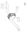
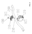
- the slider for a drive comprises a driving plate 100, applied to cover the driving unit and move under the driving forces from the driving unit, the driving plate 100 also has a steel pipe 200 fixed there and applied to move the units to be driven together.
- the methods of the steel pipe 200 fixing to the driving plate 100 in the slider for a drive as described in the present invention include, but not limited to, the following three ways: first, they are fixed by screws; second, they are fixed by fixing pins; third, they are fixed by a method of splitting tubes.
- the slider for a drive further includes a driving plate head cover 300, applied to form a steel channel for a steel pipe 200 to go through, after engaging with the driving plate 100;
- the driving plate 100 also comprises a first inner threaded pathway 110, and screw holes 210 are arranged at the according positions in the steel pipe 200, a second inner threaded pathway 310 is arranged at the according position in the driving plate head cover 300.
- the screw passes through the second inner threaded pathway 310, the screw holes 210 and the first inner threaded pathway 110, before fixing the driving plate head cover 300 and the steel pipe 200 onto the driving plate 100.
- first inner threaded pathway 110 penetrates through the screw hole 210, that is, the steel pipe 200 is restricted by the first inner threaded pathway 110 to avoid sliding left or right horizontally.
- At least one second inner threaded pathways 310 are arranged in the driving plate head cover 300, the same number of screw holes 210 as that of the second inner threaded pathways 310 are arranged in the driving plate 100. More specifically, in the embodiment I, at least one screw 400 is applied to fix the steel tube 200 onto the driving plate 100.
- screw pathways 120 are also arranged in the driving plate 100, where screws pass through and connect to a driving unit.
- the driving unit starts to move, it drives the driving plate 100 to move by the screw, then the driving plate 100 drives the steel pipe 200 to move together, in such a way, all units to be driven connecting to the pipe 200 will move together.
- the slider for a drive as described in the embodiment I owns a simple machining and assembling process, has a relatively low cost, and is able to meet the user's requirements.
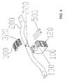
- the slider for a drive further includes a driving plate head cover 300, applied to form a steel channel for a steel pipe 200 to go through, after engaging with the driving plate 100;
- the driving plate head cover 300 comprises first fixed pin pathways 320, and second fixed pin pathways 130 are arranged at the according positions in the driving plate 100, third fixed pin pathways 220 are arranged in the according position in the steel pipe 200;
- Fixed pins 500 pass through the first fixed pin pathways 320, the second pin pathways 130 and the third fixed pin pathways 220, fixing the driving plate head cover 300 and the steel pipe 200 onto the driving plate 100.
- a restricting column is arranged on the driving plate 200, and a pathway for the restricting column is arranged at the according position in the steel pipe 200, the restricting column penetrates the restricting column pathway, that is, the steel pipe 200 is restricted by the restricting column, to avoid sliding left or right horizontally.
- At least one first fixed pin pathway 320 is arranged in the driving plate head cover 300, the same number of second fixed pin pathways 130 as that of the first fixed pin pathways 320 are arranged in the driving plate 100, and the same number of third fixed pin pathways 220 as that of the first fixed pin pathways 320 are arranged in the steel pipe 200. More specifically, in the embodiment II, at least one fixed pin 500 is applied to fix the steel tube 200 onto the driving plate 100.
- screw pathways 120 are also arranged in the driving plate 100, where screws pass through and connect to a driving unit.
- the driving unit starts to move, it drives the driving plate 100 to move through the screw, while the driving plate 100 drives the steel pipe 200 to move together, in such a way, all units to be driven connecting to the pipe 200 will move together.
- the slider for a drive as described in the embodiment II owns a simple machining and assembling process, has a relatively low cost, and is able to meet the user's requirements.
- the slider for a drive further includes a driving plate head cover 300, applied to form a steel channel for a steel pipe 200 to go through, after engaging with the driving plate 100;
- the steel pipe 200 comprises an intermediate pipe 201, a first split tube 202 fixedly arranging at one end of the intermediate tube 201 and a second split tube 203 fixedly arranging at the other end of the intermediate tube 201; both the driving plate 100 and the driving plate head cover 300 are fixed on the intermediate tube 201.
- third inner threaded pathways 2011 are arranged at both ends of the intermediate tube 201, and a fourth inner threaded pathway 2021 is arranged at the according position in the first split tube, a fifth inner threaded pathway 2031 is arranged at the according position in the second split tube; while a first fixing screw 600 penetrates the fourth inner threaded pathway 2021 and the third inner threaded pathway 2011 in sequence, before fixing the first split tube 202 into the intermediate tube 201; and a second fixing screw 700 penetrates the fifth inner threaded pathway 2031 and the third inner threaded pathway 2011 in sequence, before fixing the second split tube 203 into the intermediate tube 201.
- connection between the first split tube 202 or the second split tube 203 and the intermediate tube 201 is not limited to the fixing method with screws, it can also be fixed by other methods including fixing axles, as long as it can fix the first split tube 202 and the second split tube 203 solidly to the intermediate tube 201.
- screw pathways 120 are also arranged in the driving plate 100, where screws pass through and connect to a driving unit.
- the driving unit starts to move, it drives the driving plate 100 to move through the screws, and the driving plate 100 drives the steel pipe 200 to move together, in such a way, all units to be driven connecting to the pipe 200 will move together.
- the slider for a drive as described in the embodiment III owns a simple machining and assembling process, has a relatively low cost, and is able to meet the user's requirements.
- the slider for a drive as provided in the present invention comprises a driving plate applied to cover the driving unit and move under the driving forces from the driving unit, the driving plate also has a steel pipe fixed there, applied to move the units to be driven together.
- the slider for a drive as provided in the present invention owns a simple machining and assembling process, has a relatively low cost, and is able to meet the user's requirements.
Landscapes
- Engineering & Computer Science (AREA)
- General Engineering & Computer Science (AREA)
- Mechanical Engineering (AREA)
- Aviation & Aerospace Engineering (AREA)
- Transportation (AREA)
- Bearings For Parts Moving Linearly (AREA)
- Transmission Devices (AREA)
- Multiple-Way Valves (AREA)
Abstract
Description
- This application claims the priority of Chinese patent application No.
201520286725.1, filed on May.6, 2015 - The present invention relates to the field of driving blocks technology area, and more particularly, to a slider for a drive.
- A driving block (i.e., a slider) is often used as a connection unit for medical devices, sofa seats and else, which is a connection component applied to move the units to be driven together under a driving force. However, the existing technologies for driving blocks have some complexities in machining and assembling, and a higher production cost.
- Therefore, the prior art needs to be improved and developed.
- The technical problems to be solved in the present invention is, aiming at the defects of the prior art, providing a slider for a drive, in order to solve the problems in the prior art, that the machining and assembling for driving blocks is some kind of complicated, and their production cost is relatively high.
- The technical solution of the present invention to solve the technical problems is as follows:
- A slider for a drive, wherein, it comprises a driving plate applied to cover the driving unit and move under the driving forces from the driving unit, the driving plate also has a steel pipe fixed together, applied to move the units to be driven together.
- The slider for the drive, wherein, it further comprises a driving plate head cover, applied to form a steel channel for a steel pipe to go through, after engaging with the driving plate; the driving plate also comprises a number of first inner threaded pathways, and screw holes are arranged at the according positions in the steel pipe, a number of second inner threaded pathways are arranged at the according positions in the driving plate head cover. Screws pass through the second inner threaded pathways, the screw holes and the first inner threaded pathways, before fixing the driving plate head cover and the steel pipe onto the driving plate.
- The slider for the drive, wherein, at least one second inner threaded pathway is arranged in a driving plate head cover, the same number of screw holes as that of the second inner threaded pathways are arranged in the steel pipe, and the same number of first inner threaded pathways as that of the second inner threaded pathways are arranged in the driving plate.
- The slider for the drive, wherein, it further comprises a driving plate head cover, applied to form a steel channel for a steel pipe to go through, after engaging with the driving plate; a number of first fixed pin pathways are arranged in the driving plate head cover, second fixed pin pathways are arranged at the according positions in the driving plate, and third fixed pin pathways are arranged at the according positions in the steel pipe; while the fixed pins pass through the first fixed pin pathways, the second fixed pin pathways and the third fixed pin pathways in sequence, then fix the driving plate head cover and the steel pipe onto the driving plate.
- The slider for the drive, wherein, at least one first fixed pin pathways are arranged in the driving plate head cover, the same number of second fixed pin pathways as that of the first fixed pin pathways are arranged in the driving plate, and the same number of third fixed pin pathways as that of the first fixed pin pathways are arranged in the steel pipe.
- The slider for the drive, wherein, it further comprises a driving plate head cover, applied to form a steel channel for a steel pipe to go through, after engaging with the driving plate; the steel pipe comprises an intermediate pipe, a first split tube fixedly arranged at one end of the intermediate tube and a second split tube fixedly arranged at the other end of the intermediate tube; both the driving plate and the driving plate head cover are fixed on the intermediate tube.
- Benefits: the slider for the drive provided in the present invention, owes a simple machining and assembling process, a relatively lower production cost, and is able to meet the user's requirements.
-
FIG. 1 illustrates a schematic diagram of an embodiment I on the slider for a drive as described in the present invention. -
FIG. 2 illustrates an explored diagram of the embodiment I on the slider for a drive as shown inFig. 1 . -
FIG. 3 illustrates a schematic diagram of an embodiment II on the slider for a drive as described in the present invention. -
FIG. 4 illustrates an explored diagram of the embodiment II on the slider for a drive as shown inFig. 3 . -
FIG. 5 illustrates a schematic diagram of an embodiment III on the slider for a drive as described in the present invention. -
FIG. 6 illustrates an explored diagram of the embodiment III on the slider for a drive as shown inFig. 5 . - The present invention provides a slider for a drive, In order to make the purpose, technical solution and the advantages of the present invention clearer and more explicit, further detailed descriptions of the present invention are stated here, referring to the attached drawings and some embodiments of the present invention. It should be understood that the detailed embodiments of the invention described here are used to explain the present invention only, instead of limiting the present invention.
- Referring to
Fig. 1 ,Fig. 3 andFig. 5 together, wherein,Fig. 1 illustrates a schematic diagram of the embodiment I on the slider for a drive as described in the present invention,Fig. 3 illustrates a schematic diagram of the embodiment II on the slider for a drive as described in the present invention,Fig. 5 illustrates a schematic diagram of the embodiment III on the slider for a drive as described in the present invention. The slider for a drive comprises adriving plate 100, applied to cover the driving unit and move under the driving forces from the driving unit, thedriving plate 100 also has asteel pipe 200 fixed there and applied to move the units to be driven together. - The methods of the
steel pipe 200 fixing to thedriving plate 100 in the slider for a drive as described in the present invention include, but not limited to, the following three ways: first, they are fixed by screws; second, they are fixed by fixing pins; third, they are fixed by a method of splitting tubes. In order to illustrate the slider for a drive as described in the present invention more clearly, specific embodiments according to the three fixing methods are described below. - As shown in
Fig.1 andFig.2 together, the slider for a drive further includes a drivingplate head cover 300, applied to form a steel channel for asteel pipe 200 to go through, after engaging with thedriving plate 100; thedriving plate 100 also comprises a first inner threadedpathway 110, andscrew holes 210 are arranged at the according positions in thesteel pipe 200, a second inner threadedpathway 310 is arranged at the according position in the drivingplate head cover 300. The screw passes through the second inner threadedpathway 310, thescrew holes 210 and the first inner threadedpathway 110, before fixing the drivingplate head cover 300 and thesteel pipe 200 onto thedriving plate 100. - Further, the first inner threaded
pathway 110 penetrates through thescrew hole 210, that is, thesteel pipe 200 is restricted by the first inner threadedpathway 110 to avoid sliding left or right horizontally. - Further, at least one second inner threaded
pathways 310 are arranged in the drivingplate head cover 300, the same number ofscrew holes 210 as that of the second inner threadedpathways 310 are arranged in thedriving plate 100. More specifically, in the embodiment I, at least onescrew 400 is applied to fix thesteel tube 200 onto thedriving plate 100. - In specific implementations, referring to
Fig.1 andFig. 2 ,screw pathways 120 are also arranged in thedriving plate 100, where screws pass through and connect to a driving unit. When the driving unit starts to move, it drives thedriving plate 100 to move by the screw, then thedriving plate 100 drives thesteel pipe 200 to move together, in such a way, all units to be driven connecting to thepipe 200 will move together. It shows that, the slider for a drive as described in the embodiment I owns a simple machining and assembling process, has a relatively low cost, and is able to meet the user's requirements. - As shown in
Fig. 3 andFig. 4 together, the slider for a drive further includes a drivingplate head cover 300, applied to form a steel channel for asteel pipe 200 to go through, after engaging with thedriving plate 100; the drivingplate head cover 300 comprises firstfixed pin pathways 320, and secondfixed pin pathways 130 are arranged at the according positions in thedriving plate 100, thirdfixed pin pathways 220 are arranged in the according position in thesteel pipe 200; Fixedpins 500 pass through the first fixedpin pathways 320, thesecond pin pathways 130 and the third fixedpin pathways 220, fixing the drivingplate head cover 300 and thesteel pipe 200 onto thedriving plate 100. - Further, a restricting column is arranged on the
driving plate 200, and a pathway for the restricting column is arranged at the according position in thesteel pipe 200, the restricting column penetrates the restricting column pathway, that is, thesteel pipe 200 is restricted by the restricting column, to avoid sliding left or right horizontally. - Further, at least one first fixed
pin pathway 320 is arranged in the drivingplate head cover 300, the same number of secondfixed pin pathways 130 as that of the firstfixed pin pathways 320 are arranged in thedriving plate 100, and the same number of thirdfixed pin pathways 220 as that of the firstfixed pin pathways 320 are arranged in thesteel pipe 200. More specifically, in the embodiment II, at least one fixedpin 500 is applied to fix thesteel tube 200 onto thedriving plate 100. - In specific implementations, referring to
Fig.3 andFig.4 ,screw pathways 120 are also arranged in thedriving plate 100, where screws pass through and connect to a driving unit. When the driving unit starts to move, it drives thedriving plate 100 to move through the screw, while thedriving plate 100 drives thesteel pipe 200 to move together, in such a way, all units to be driven connecting to thepipe 200 will move together. It shows that, the slider for a drive as described in the embodiment II owns a simple machining and assembling process, has a relatively low cost, and is able to meet the user's requirements. - As shown in
Fig.5 andFig.6 together, the slider for a drive further includes a drivingplate head cover 300, applied to form a steel channel for asteel pipe 200 to go through, after engaging with thedriving plate 100; thesteel pipe 200 comprises anintermediate pipe 201, afirst split tube 202 fixedly arranging at one end of theintermediate tube 201 and asecond split tube 203 fixedly arranging at the other end of theintermediate tube 201; both thedriving plate 100 and the drivingplate head cover 300 are fixed on theintermediate tube 201. - Further, third inner threaded
pathways 2011 are arranged at both ends of theintermediate tube 201, and a fourth inner threadedpathway 2021 is arranged at the according position in the first split tube, a fifth inner threadedpathway 2031 is arranged at the according position in the second split tube; while afirst fixing screw 600 penetrates the fourth inner threadedpathway 2021 and the third inner threadedpathway 2011 in sequence, before fixing thefirst split tube 202 into theintermediate tube 201; and asecond fixing screw 700 penetrates the fifth inner threadedpathway 2031 and the third inner threadedpathway 2011 in sequence, before fixing thesecond split tube 203 into theintermediate tube 201. - In specific implementations, the connection between the
first split tube 202 or thesecond split tube 203 and theintermediate tube 201 is not limited to the fixing method with screws, it can also be fixed by other methods including fixing axles, as long as it can fix thefirst split tube 202 and thesecond split tube 203 solidly to theintermediate tube 201. - In specific implementations, referring to
Fig.5 andFig.6 ,screw pathways 120 are also arranged in thedriving plate 100, where screws pass through and connect to a driving unit. When the driving unit starts to move, it drives thedriving plate 100 to move through the screws, and thedriving plate 100 drives thesteel pipe 200 to move together, in such a way, all units to be driven connecting to thepipe 200 will move together. It shows that, the slider for a drive as described in the embodiment III owns a simple machining and assembling process, has a relatively low cost, and is able to meet the user's requirements. - All together, the slider for a drive as provided in the present invention, comprises a driving plate applied to cover the driving unit and move under the driving forces from the driving unit, the driving plate also has a steel pipe fixed there, applied to move the units to be driven together. the slider for a drive as provided in the present invention owns a simple machining and assembling process, has a relatively low cost, and is able to meet the user's requirements.
- It should be understood that, the application of the present invention is not limited to the examples listed. It will be possible for a person skilled in the art to make modification or replacements according to the descriptions, which shall all fall within the scope of protection in the appended claims of the present invention.
Claims (6)
- A slider for a drive, wherein, it comprises a driving plate applied to cover a driving unit and move under driving forces from the driving unit, the driving plate also connects fixedly to a steel pipe, and the steel pipe is applied to move units to be driven together.
- The slider for the drive according to claim 1, wherein, it further comprises a driving plate head cover, applied to form a steel channel for a steel pipe to go through, after engaging with the driving plate; the driving plate also comprises first inner threaded pathways, screw holes are arranged at the according positions in the steel pipe, and second inner threaded pathways are arranged at the according positions in the driving plate head cover, the screws pass through the second inner threaded pathways, the screw holes and the first inner threaded pathways, fixing the driving plate head cover and the steel pipe onto the driving plate.
- The slider for the drive according to claim 2, wherein, at least one second inner threaded pathway is arranged in a driving plate head cover, the same number of screw holes as that of the second inner threaded pathways are arranged in the steel pipe, and the same number of first inner threaded pathways as that of the second inner threaded pathways are arranged in the driving plate.
- The slider for the drive according to claim 1, wherein, it comprises a driving plate head cover, applied to form a steel channel for a steel pipe to go through, after engaging with the driving plate; a number of first fixed pin pathways are arranged at the according positions in the driving plate head cover, second fixed pin pathways are arranged at the according positions in the driving plate, and third fixed pin pathways are arranged at the according positions in the steel pipe; and the fixed pins pass through the first fixed pin pathways, the second fixed pin pathways and the third fixed pin pathways in sequence, then fix the driving plate head cover and the steel pipe onto the driving plate.
- The slider for the drive according to claim 4, wherein, at least one first fixed pin pathways are arranged in the driving plate head cover, same number of second fixed pin pathways as that of the first fixed pin pathways are arranged in the driving plate, and same number of third fixed pin pathways as that of the first fixed pin pathways are arranged in the steel pipe.
- The slider for the drive according to claim 1, wherein, it further comprises a driving plate head cover, applied to form a steel channel for a steel pipe to go through, after engaging with the driving plate; the steel pipe includes an intermediate pipe, a first split tube fixedly arranging at one end of the intermediate tube and a second split tube fixedly arranging at the other end of the intermediate tube; both the driving plate and the driving plate head cover are fixed on the intermediate tube.
Applications Claiming Priority (1)
| Application Number | Priority Date | Filing Date | Title |
|---|---|---|---|
| CN201520286725.1U CN204628504U (en) | 2015-05-06 | 2015-05-06 | A kind of slide blocks on driver |
Publications (2)
| Publication Number | Publication Date |
|---|---|
| EP3091252A2 true EP3091252A2 (en) | 2016-11-09 |
| EP3091252A3 EP3091252A3 (en) | 2017-01-04 |
Family
ID=54047537
Family Applications (1)
| Application Number | Title | Priority Date | Filing Date |
|---|---|---|---|
| EP15185638.2A Withdrawn EP3091252A3 (en) | 2015-05-06 | 2015-09-17 | A slider for a drive |
Country Status (3)
| Country | Link |
|---|---|
| US (1) | US10323741B2 (en) |
| EP (1) | EP3091252A3 (en) |
| CN (1) | CN204628504U (en) |
Families Citing this family (2)
| Publication number | Priority date | Publication date | Assignee | Title |
|---|---|---|---|---|
| CN205480073U (en) * | 2015-12-09 | 2016-08-17 | 炼马机电(深圳)有限公司 | Driving block for connection |
| US11639118B2 (en) * | 2019-06-11 | 2023-05-02 | Italdesign-Giugiaro S.P.A. | System for positioning a component on the floor of the passenger compartment of a vehicle |
Family Cites Families (22)
| Publication number | Priority date | Publication date | Assignee | Title |
|---|---|---|---|---|
| US801409A (en) * | 1904-10-04 | 1905-10-10 | William Clifford Smith | Pipe-hanger. |
| US924743A (en) * | 1907-07-16 | 1909-06-15 | Cary S Cox | Rotary rock-drill. |
| US3046040A (en) * | 1960-05-31 | 1962-07-24 | Forrest E Luper | Joint structure for tubing |
| US3101006A (en) * | 1960-10-13 | 1963-08-20 | Ingersoll Rand Co | Drill mounting |
| US3145013A (en) * | 1961-08-08 | 1964-08-18 | Blazon Inc | Playground swing |
| FR1562272A (en) * | 1968-02-23 | 1969-04-04 | ||
| US3524627A (en) * | 1968-05-24 | 1970-08-18 | Gibraltar Fence Co Inc | Device for attaching a rail to a fence post |
| US3652105A (en) * | 1970-05-08 | 1972-03-28 | Wald Mfg Co Inc | Bicycle kickstand |
| DE2310170A1 (en) * | 1973-03-01 | 1974-09-05 | Kratzer F Mefa Duebel Gmbh | CLAMP FOR FASTENING A LONGEST BODY, IN PARTICULAR A PIPE |
| FR2442366A1 (en) * | 1978-11-27 | 1980-06-20 | Monnier Georges | Arcuate clip of elastic moulding material for supporting tubes etc. - pref. made of polyamide for sprung engagement of the tube |
| USD264379S (en) * | 1980-02-11 | 1982-05-11 | Raymond Slinkard | Adjustable, detachable handle suitable for use on wheeled, hospital-type IV stands and the like |
| US4466309A (en) * | 1982-04-05 | 1984-08-21 | Maddak, Inc. | Adjustably positioned handgrip for ambulatory aids |
| AU585155B2 (en) * | 1987-05-05 | 1989-06-08 | Gec Power Distribution (Proprietary) Limited | Cable clamp |
| ES2128083T3 (en) * | 1994-10-18 | 1999-05-01 | Okin Ges Fur Antriebstechnik M | DRIVE FOR THE ADJUSTMENT OF PARTS OF SEAT AND BED FURNITURE. |
| JP3164267B2 (en) * | 1994-10-21 | 2001-05-08 | 新東工業株式会社 | Electric cylinder |
| US6334733B1 (en) * | 1998-12-07 | 2002-01-01 | James William Tyson | Pipe connector |
| US6517157B1 (en) * | 2001-03-16 | 2003-02-11 | Johnson Controls Technology Company | Apparatus for adjusting a seat belt |
| US7278331B2 (en) * | 2003-08-27 | 2007-10-09 | Lear Corporation | Drive nut with structural extrusion drive area for vehicle seat adjuster |
| US20070172312A1 (en) * | 2006-01-17 | 2007-07-26 | Leao Wang | Coupling for joining connection tubes of an exercise apparatus |
| JP2010047172A (en) * | 2008-08-22 | 2010-03-04 | Aisin Seiki Co Ltd | Feeding device |
| DE602008006552D1 (en) * | 2008-09-10 | 2011-06-09 | Man Wah Furniture Mfg Huizhou Co Ltd | Control for adjusting seat and reclining furniture parts |
| EP2690314B1 (en) * | 2012-07-27 | 2017-03-01 | Siemens Aktiengesellschaft | Spindle drive |
-
2015
- 2015-05-06 CN CN201520286725.1U patent/CN204628504U/en not_active Expired - Fee Related
- 2015-09-17 EP EP15185638.2A patent/EP3091252A3/en not_active Withdrawn
- 2015-09-22 US US14/861,166 patent/US10323741B2/en not_active Expired - Fee Related
Non-Patent Citations (1)
| Title |
|---|
| None |
Also Published As
| Publication number | Publication date |
|---|---|
| CN204628504U (en) | 2015-09-09 |
| US10323741B2 (en) | 2019-06-18 |
| EP3091252A3 (en) | 2017-01-04 |
| US20160327147A1 (en) | 2016-11-10 |
Similar Documents
| Publication | Publication Date | Title |
|---|---|---|
| EP3095660A3 (en) | A method and system for increasing driver awareness by modifying the frequency of a visual system | |
| EP3091252A2 (en) | A slider for a drive | |
| EP2670158A3 (en) | Collaborative video application for remote servicing | |
| WO2011017073A3 (en) | Movable partitions, header assemblies for movable partitions, and methods of forming header assemblies for movable partitions | |
| CN104299527A (en) | Screen body splicing device and LED leasing screen | |
| EP3213977A3 (en) | Steering system | |
| NO20052173L (en) | Optical imaging system that has a field of view | |
| CN101589890A (en) | The carriage that is used for slide rail | |
| WO2013036140A3 (en) | A die retainer system for a clamp die and method of operation of same | |
| WO2009143443A3 (en) | Rigging table for assembling trusses and method of use therefor | |
| EP4006521A4 (en) | Vehicle driving testing device, driving performance testing system, and driving performance testing method | |
| WO2008129995A1 (en) | Bone forming device and method of forming bone | |
| EP2621077A3 (en) | Medium voltage inverter control apparatus and medium voltage inverter system | |
| CN102909281B (en) | A kind of copper pipe end locking device of electric tube expander | |
| CN104683663A (en) | Monitoring camera | |
| FR2981420B1 (en) | ASYMMETRIC ANTI-ROTATION DEVICE AND SCREW JACK WITH SUCH A DEVICE | |
| CN105345346B (en) | Leaf spring suspension installing tool | |
| EP4059431A4 (en) | System and method for guiding electrocardiogram lead | |
| WO2007051085A3 (en) | Adjustable clamp system | |
| DE602005005450D1 (en) | QUICK COUPLING / MOUNTING SYSTEM FOR LIFTING GUIDES | |
| US20170167583A1 (en) | Driving block for connections | |
| CN204640418U (en) | A kind of easily detachable former bamboo unwinder | |
| FR3061129B1 (en) | METHOD FOR MANUFACTURING A THERMOPHONIC ISOLATION MODULE FOR AIRCRAFT COMPRISING A BENDING STEP | |
| CN104400740B (en) | The IGCT of vertical adjusting clamp opening and closing changes instrument | |
| CN203931493U (en) | A kind of device of exempting from tool assemble and dismounting hard disk |
Legal Events
| Date | Code | Title | Description |
|---|---|---|---|
| PUAI | Public reference made under article 153(3) epc to a published international application that has entered the european phase |
Free format text: ORIGINAL CODE: 0009012 |
|
| 17P | Request for examination filed |
Effective date: 20150917 |
|
| AK | Designated contracting states |
Kind code of ref document: A2 Designated state(s): AL AT BE BG CH CY CZ DE DK EE ES FI FR GB GR HR HU IE IS IT LI LT LU LV MC MK MT NL NO PL PT RO RS SE SI SK SM TR |
|
| AX | Request for extension of the european patent |
Extension state: BA ME |
|
| PUAL | Search report despatched |
Free format text: ORIGINAL CODE: 0009013 |
|
| AK | Designated contracting states |
Kind code of ref document: A3 Designated state(s): AL AT BE BG CH CY CZ DE DK EE ES FI FR GB GR HR HU IE IS IT LI LT LU LV MC MK MT NL NO PL PT RO RS SE SI SK SM TR |
|
| AX | Request for extension of the european patent |
Extension state: BA ME |
|
| RIC1 | Information provided on ipc code assigned before grant |
Ipc: F16L 3/10 20060101ALI20161128BHEP Ipc: F16H 25/24 20060101AFI20161128BHEP Ipc: F16H 25/20 20060101ALN20161128BHEP |
|
| 17Q | First examination report despatched |
Effective date: 20191007 |
|
| STAA | Information on the status of an ep patent application or granted ep patent |
Free format text: STATUS: THE APPLICATION IS DEEMED TO BE WITHDRAWN |
|
| 18D | Application deemed to be withdrawn |
Effective date: 20200218 |