EP3090943A1 - Landing gear including a bogie beam assembly and method for coupling an axle to a bogie beam thereof - Google Patents
Landing gear including a bogie beam assembly and method for coupling an axle to a bogie beam thereof Download PDFInfo
- Publication number
- EP3090943A1 EP3090943A1 EP16168399.0A EP16168399A EP3090943A1 EP 3090943 A1 EP3090943 A1 EP 3090943A1 EP 16168399 A EP16168399 A EP 16168399A EP 3090943 A1 EP3090943 A1 EP 3090943A1
- Authority
- EP
- European Patent Office
- Prior art keywords
- axle
- bogie beam
- sleeve portion
- aft
- landing gear
- Prior art date
- Legal status (The legal status is an assumption and is not a legal conclusion. Google has not performed a legal analysis and makes no representation as to the accuracy of the status listed.)
- Granted
Links
Images



Classifications
-
- B—PERFORMING OPERATIONS; TRANSPORTING
- B64—AIRCRAFT; AVIATION; COSMONAUTICS
- B64C—AEROPLANES; HELICOPTERS
- B64C25/00—Alighting gear
- B64C25/32—Alighting gear characterised by elements which contact the ground or similar surface
- B64C25/34—Alighting gear characterised by elements which contact the ground or similar surface wheeled type, e.g. multi-wheeled bogies
- B64C25/36—Arrangements or adaptations of wheels, tyres or axles in general
-
- B—PERFORMING OPERATIONS; TRANSPORTING
- B64—AIRCRAFT; AVIATION; COSMONAUTICS
- B64C—AEROPLANES; HELICOPTERS
- B64C25/00—Alighting gear
- B64C25/02—Undercarriages
- B64C25/08—Undercarriages non-fixed, e.g. jettisonable
- B64C25/10—Undercarriages non-fixed, e.g. jettisonable retractable, foldable, or the like
- B64C25/12—Undercarriages non-fixed, e.g. jettisonable retractable, foldable, or the like sideways
-
- B—PERFORMING OPERATIONS; TRANSPORTING
- B64—AIRCRAFT; AVIATION; COSMONAUTICS
- B64C—AEROPLANES; HELICOPTERS
- B64C25/00—Alighting gear
- B64C25/32—Alighting gear characterised by elements which contact the ground or similar surface
- B64C25/58—Arrangements or adaptations of shock-absorbers or springs
Definitions
- the present disclosure relates to landing gear and more particularly, to a landing gear including a bogie beam assembly and method for coupling an axle to a bogie beam thereof.
- Bogie type landing gear supports an aircraft while the aircraft is on the ground.
- Bogie type landing gear may include a shock strut assembly and an elongated bogie beam that supports one or more pairs of wheels.
- Axles for carrying the wheels are indirectly coupled to the bogie beam by an axle plug and axle retention spool. Using the axle plug and axle retention spool to couple the axle with the bogie beam undesirably adds weight, cost, and part count to a bogie beam assembly.
- the bogie beam assembly comprises a bogie beam, an axle, and at least one retention bolt.
- the bogie beam comprises an elongated main body portion having an end portion disposed between a forward sleeve portion and an aft sleeve portion that are transverse to the elongated main body portion.
- the axle extends through the forward sleeve portion, the end portion, and the aft sleeve portion.
- the at least one retention bolt is secured through at least one of forward sleeve portion and the axle and the aft sleeve portion and the axle.
- a landing gear is provided according to various embodiments.
- the landing gear comprises a shock strut assembly and a bogie beam assembly coupled to the shock strut assembly.
- the bogie beam assembly comprises a bogie beam, an axle, and at least one retention bolt.
- the bogie beam comprises an elongated main body portion having an end portion disposed between a forward sleeve portion and an aft sleeve portion that are transverse to the elongated main body portion.
- the axle extends through the forward sleeve portion, the end portion, and the aft sleeve portion.
- the at least one retention bolt is secured through at least one of forward sleeve portion and the axle and the aft sleeve portion and the axle.
- a method for coupling an axle to a bogie beam of a landing gear comprises inserting an axle to extend through a forward sleeve portion, an end portion, and an aft sleeve portion of the bogie beam.
- the bogie beam comprises an elongated main body portion having the end portion disposed between the forward sleeve portion and the aft sleeve portion that are transverse to the elongated body portion.
- At least one retention bolt is inserted and secured, in a direction normal to a longitudinal axis of the axle, through at least one of the forward sleeve portion and the axle and the aft sleeve portion and the axle.
- the axle extends beyond the forward sleeve portion to define an exposed forward axle portion and beyond the aft sleeve portion to define an exposed aft axle portion.
- the retention bolt extends and is secured in a direction normal to a longitudinal axis of the axle.
- the bogie beam is generally I-shaped.
- the forward and aft sleeve portions each include a bore for the axle.
- An inner surface of the forward sleeve portion and the aft sleeve portion surrounds an outer surface of the axle.
- the retention bolt transfers axial loads from the axle and directly into the bogie beam.
- references to "various embodiments”, “one embodiment”, “an embodiment”, “an example embodiment”, etc. indicate that the embodiment described may include a particular feature, structure, or characteristic, but every embodiment may not necessarily include the particular feature, structure, or characteristic. Moreover, such phrases are not necessarily referring to the same embodiment. Further, when a particular feature, structure, or characteristic is described in connection with an embodiment, it is submitted that it is within the knowledge of one skilled in the art to affect such feature, structure, or characteristic in connection with other embodiments whether or not explicitly described. After reading the description, it will be apparent to one skilled in the relevant art(s) how to implement the disclosure in alternative embodiments.
- Various embodiments are directed to a landing gear including a bogie beam assembly and method for coupling an axle to a bogie beam thereof.
- Various embodiments as described in the present disclosure reduce weight, cost, and part count of the landing gear and bogie beam assembly thereof over conventional landing gear and conventional bogie beam assemblies using a straight elongated bogie beam and a plug and/or axle retention spool between the axle and the bogie beam for coupling the axle and bogie beam together, undesirably adding weight, cost, and part count to the landing gear and bogie beam assembly thereof.
- the landing gear 2 for aircraft generally comprises a shock strut assembly 4 coupled to a bogie beam assembly 6.
- the bogie beam assembly 6 generally comprises a bogie beam 8, an axle 10 for carrying wheels, and at least one retention bolt 12 for directly coupling the axle 10 to the bogie beam 8.
- FIGS. 1 and 2 depict a single retention bolt. It is to be understood that the number of retention bolts may vary from other than depicted and additional retention bolts may be used.
- the at least one retention bolt 12 may be secured by a nut 15 ( FIG. 4 ) or the like.
- the bogie beam 8 comprises an elongated main body portion 14 having an end portion 16 disposed between a forward sleeve portion 18 and an opposing aft sleeve portion 20 that are transverse to the elongated main body portion 14.
- the bogie beam 8 may be generally I-shaped.
- the forward sleeve portion 18 and the aft sleeve portion 20 each include a bore for receiving the axle 10 as hereinafter described.
- the axle 10 extends through the forward sleeve portion 18, the end portion 16, and the aft sleeve portion 20.
- the axle 10 is configured for carrying at least one pair of wheels of the landing gear 2.
- the axle 10 extends beyond the forward sleeve portion 18 to define an exposed forward axle portion 22 and beyond the aft sleeve portion 20 to define an exposed aft axle portion 24.
- An inner surface of the forward sleeve portion 18 and the aft sleeve portion 20 directly contact an outer surface of the axle 10 (i.e., there is no intervening plug and/or axle retention spool between the axle and the bogie beam as in a conventional landing gear and bogie beam assembly).
- the retention bolt 12 is depicted in FIGS. 1 , 2 , and 4 as being secured through the aft sleeve portion 24 and the axle 10.
- FIG. 3 illustrates a bogie beam assembly 6' in accordance with various embodiments.
- Bogie beam assembly 6' comprises a bogie beam 8', an axle 10' for carrying wheels, and at least one retention bolt 12a and 12b for directly coupling the axle 10' to the bogie beam 8'.
- the at least one retention bolt 12a and 12b may be secured by a nut 15' ( FIG. 4 ) or the like.
- Bogie beam 8' comprises an elongated main body portion 14' having an end portion 16' disposed between a forward sleeve portion 18' and an opposing aft sleeve portion 20' that are transverse to the elongated main body portion 14'.
- the bogie beam 8' may be generally I-shaped.
- the forward sleeve portion 18' and the aft sleeve portion 20' each include a bore for receiving the axle 10' as hereinafter described.
- the axle 10' extends through the forward sleeve portion 18', the end portion 16', and the aft sleeve portion 20'.
- the axle 10' is configured for carrying at least one pair of wheels of the landing gear.
- the axle 10' extends beyond the forward sleeve portion 18' to define an exposed forward axle portion 22' and beyond the aft sleeve portion 20' to define an exposed aft axle portion 24'.
- An inner surface of the forward sleeve portion 18' and the aft sleeve portion 20' directly contact an outer surface of the axle 10' (i.e., there is no intervening plug and/or axle retention spool between the axle and the bogie beam as in a conventional landing gear and bogie beam assembly).
- FIG. 3 depicts a first retention bolt 12a and a second retention bolt 12b.
- first retention bolt 12a is secured through the forward sleeve portion 18' and the axle 10' and the second retention bolt 12b is secured through the aft sleeve portion 20' and the axle 10' (see also FIG. 4 ). While first and second retention bolts 12a and 12b are depicted, it is to be understood that a fewer (e.g., FIGS 1 and 2 ) or a greater number of retention bolts may be used to directly couple the axle 10' to the bogie beam 8'.
- a method 50 for coupling the axle to the bogie beam of the landing gear begins by inserting the axle to extend through the forward sleeve portion, the end portion, and the aft sleeve portion of the bogie beam (step 200). Still referring to FIG. 5 , according to various embodiments, the method 50 for coupling the axle to the bogie beam of the landing gear 2 continues by inserting (step 300) and securing (step 400) the at least one retention bolt through at least one of the forward sleeve portion and the axle and the aft sleeve portion and the axle. The at least one retention bolt is inserted in a direction normal (perpendicular) to the longitudinal axis of the axle as depicted in FIG. 4 . The at least one retention bolt may be secured by a nut or the like.
- the axial loads are transferred directly from the axle 10/10' directly to the bogie beam 8/8', rather than from the axle to an intervening axle plug and/or axle retention spool and then to the bogie beam as in a conventional bogie beam assembly.
- the axle 10/10' is directly coupled to the bogie beam 8/8' with the axle directly contacting the bogie beam.
- the landing gear 2 and the bogie beam assembly 6/6' described in the present disclosure provide weight, cost, and part count advantages over a conventional landing gear including a conventional bogie beam assembly using an axle plug and/or axle retention spool to retain or couple the axle to the bogie beam.
Landscapes
- Engineering & Computer Science (AREA)
- Mechanical Engineering (AREA)
- Aviation & Aerospace Engineering (AREA)
- Gears, Cams (AREA)
Abstract
Description
- This application is a non-provisional of, claims priority to, and the benefit of
U.S. Provisional Patent Application No. 62/157,228 - The present disclosure relates to landing gear and more particularly, to a landing gear including a bogie beam assembly and method for coupling an axle to a bogie beam thereof.
- Landing gear supports an aircraft while the aircraft is on the ground. Bogie type landing gear may include a shock strut assembly and an elongated bogie beam that supports one or more pairs of wheels. Axles for carrying the wheels are indirectly coupled to the bogie beam by an axle plug and axle retention spool. Using the axle plug and axle retention spool to couple the axle with the bogie beam undesirably adds weight, cost, and part count to a bogie beam assembly.
- A bogie beam assembly is provided according to various embodiments. The bogie beam assembly comprises a bogie beam, an axle, and at least one retention bolt. The bogie beam comprises an elongated main body portion having an end portion disposed between a forward sleeve portion and an aft sleeve portion that are transverse to the elongated main body portion. The axle extends through the forward sleeve portion, the end portion, and the aft sleeve portion. The at least one retention bolt is secured through at least one of forward sleeve portion and the axle and the aft sleeve portion and the axle.
- A landing gear is provided according to various embodiments. The landing gear comprises a shock strut assembly and a bogie beam assembly coupled to the shock strut assembly. The bogie beam assembly comprises a bogie beam, an axle, and at least one retention bolt. The bogie beam comprises an elongated main body portion having an end portion disposed between a forward sleeve portion and an aft sleeve portion that are transverse to the elongated main body portion. The axle extends through the forward sleeve portion, the end portion, and the aft sleeve portion. The at least one retention bolt is secured through at least one of forward sleeve portion and the axle and the aft sleeve portion and the axle.
- A method is provided for coupling an axle to a bogie beam of a landing gear according to various embodiments. The method comprises inserting an axle to extend through a forward sleeve portion, an end portion, and an aft sleeve portion of the bogie beam. The bogie beam comprises an elongated main body portion having the end portion disposed between the forward sleeve portion and the aft sleeve portion that are transverse to the elongated body portion. At least one retention bolt is inserted and secured, in a direction normal to a longitudinal axis of the axle, through at least one of the forward sleeve portion and the axle and the aft sleeve portion and the axle.
- In any of the foregoing embodiments, the axle extends beyond the forward sleeve portion to define an exposed forward axle portion and beyond the aft sleeve portion to define an exposed aft axle portion. The retention bolt extends and is secured in a direction normal to a longitudinal axis of the axle. The bogie beam is generally I-shaped. The forward and aft sleeve portions each include a bore for the axle. An inner surface of the forward sleeve portion and the aft sleeve portion surrounds an outer surface of the axle. The retention bolt transfers axial loads from the axle and directly into the bogie beam.
- The drawings described herein are for illustration purposes only and are not intended to limit the scope of the present disclosure in any way. The present disclosure will become more fully understood from the detailed description and the accompanying drawings, wherein like numerals denote like elements.
-
FIG. 1 is an isometric view of an exemplary landing gear according to various embodiments; -
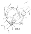
FIG. 2 is a fragmented isometric view of a portion of a bogie beam assembly according to various embodiments, illustrating a single retention bolt secured through aligned openings in an aft sleeve portion of a bogie beam and an axle for coupling the axle to the bogie beam; -
FIG. 3 is an enlarged, fragmented isometric view of a portion of a bogie beam assembly according to various embodiments, illustrating a first retention bolt secured through aligned openings in a forward sleeve portion of a bogie beam and an axle and a second retention bolt secured through aligned openings in an aft sleeve portion of the bogie beam and the axle for coupling the axle to the bogie beam; -
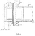
FIG. 4 is a fragmented sectional view of a portion of the bogie beam assemblies ofFIGS. 2 and3 , illustrating an aft sleeve portion of the bogie beam with the retention bolt extending and secured in a direction normal to the axle through aligned openings in the aft sleeve portion and the axle; and -
FIG. 5 is a flowchart illustrating an exemplary method for coupling the axle to the bogie beam of the landing gear in accordance with various embodiments. - All ranges and ratio limits disclosed herein may be combined. It is to be understood that unless specifically stated otherwise, references to "a," "an," and/or "the" may include one or more than one and that reference to an item in the singular may also include the item in the plural.
- The detailed description of exemplary embodiments herein makes reference to the accompanying drawings, which show exemplary embodiments by way of illustration and its best mode, and not of limitation. While these exemplary embodiments are described in sufficient detail to enable those skilled in the art to practice the invention, it should be understood that other embodiments may be realized and that logical, chemical and mechanical changes may be made without departing from the spirit and scope of the invention. For example, the steps recited in any of the method or process descriptions may be executed in any order and are not necessarily limited to the order presented. Moreover, many of the functions or steps may be outsourced to or performed by one or more third parties. Furthermore, any reference to singular includes plural embodiments, and any reference to more than one component or step may include a singular embodiment or step. Also, any reference to attached, fixed, connected or the like may include permanent, removable, temporary, partial, full and/or any other possible attachment option. Additionally, any reference to without contact (or similar phrases) may also include reduced contact or minimal contact.
- In the detailed description herein, references to "various embodiments", "one embodiment", "an embodiment", "an example embodiment", etc., indicate that the embodiment described may include a particular feature, structure, or characteristic, but every embodiment may not necessarily include the particular feature, structure, or characteristic. Moreover, such phrases are not necessarily referring to the same embodiment. Further, when a particular feature, structure, or characteristic is described in connection with an embodiment, it is submitted that it is within the knowledge of one skilled in the art to affect such feature, structure, or characteristic in connection with other embodiments whether or not explicitly described. After reading the description, it will be apparent to one skilled in the relevant art(s) how to implement the disclosure in alternative embodiments.
- Various embodiments are directed to a landing gear including a bogie beam assembly and method for coupling an axle to a bogie beam thereof. Various embodiments as described in the present disclosure reduce weight, cost, and part count of the landing gear and bogie beam assembly thereof over conventional landing gear and conventional bogie beam assemblies using a straight elongated bogie beam and a plug and/or axle retention spool between the axle and the bogie beam for coupling the axle and bogie beam together, undesirably adding weight, cost, and part count to the landing gear and bogie beam assembly thereof.
- Referring now to
FIG. 1 , alanding gear 2 according to various embodiments is depicted. As depicted inFIG. 1 , thelanding gear 2 for aircraft generally comprises ashock strut assembly 4 coupled to abogie beam assembly 6. Still referring toFIG. 1 and now toFIG. 2 , thebogie beam assembly 6, according to various embodiments, generally comprises abogie beam 8, anaxle 10 for carrying wheels, and at least oneretention bolt 12 for directly coupling theaxle 10 to thebogie beam 8.FIGS. 1 and2 depict a single retention bolt. It is to be understood that the number of retention bolts may vary from other than depicted and additional retention bolts may be used. The at least oneretention bolt 12 may be secured by a nut 15 (FIG. 4 ) or the like. - Still referring to
FIGS. 1 and2 and now toFIG. 4 , according to various embodiments, thebogie beam 8 comprises an elongatedmain body portion 14 having anend portion 16 disposed between aforward sleeve portion 18 and an opposingaft sleeve portion 20 that are transverse to the elongatedmain body portion 14. Thebogie beam 8 according to various embodiments may be generally I-shaped. Theforward sleeve portion 18 and theaft sleeve portion 20 each include a bore for receiving theaxle 10 as hereinafter described. - The
axle 10 extends through theforward sleeve portion 18, theend portion 16, and theaft sleeve portion 20. Theaxle 10 is configured for carrying at least one pair of wheels of thelanding gear 2. Theaxle 10 extends beyond theforward sleeve portion 18 to define an exposedforward axle portion 22 and beyond theaft sleeve portion 20 to define an exposed aftaxle portion 24. An inner surface of theforward sleeve portion 18 and theaft sleeve portion 20 directly contact an outer surface of the axle 10 (i.e., there is no intervening plug and/or axle retention spool between the axle and the bogie beam as in a conventional landing gear and bogie beam assembly). Theretention bolt 12 is depicted inFIGS. 1 ,2 , and4 as being secured through theaft sleeve portion 24 and theaxle 10. -
FIG. 3 illustrates a bogie beam assembly 6' in accordance with various embodiments. Bogie beam assembly 6' comprises a bogie beam 8', an axle 10' for carrying wheels, and at least oneretention bolt retention bolt FIG. 4 ) or the like. - Bogie beam 8' comprises an elongated main body portion 14' having an end portion 16' disposed between a forward sleeve portion 18' and an opposing aft sleeve portion 20' that are transverse to the elongated main body portion 14'. The bogie beam 8' according to various embodiments may be generally I-shaped. The forward sleeve portion 18' and the aft sleeve portion 20' each include a bore for receiving the axle 10' as hereinafter described. The axle 10' extends through the forward sleeve portion 18', the end portion 16', and the aft sleeve portion 20'. The axle 10' is configured for carrying at least one pair of wheels of the landing gear. The axle 10' extends beyond the forward sleeve portion 18' to define an exposed forward axle portion 22' and beyond the aft sleeve portion 20' to define an exposed aft axle portion 24'. An inner surface of the forward sleeve portion 18' and the aft sleeve portion 20' directly contact an outer surface of the axle 10' (i.e., there is no intervening plug and/or axle retention spool between the axle and the bogie beam as in a conventional landing gear and bogie beam assembly).
FIG. 3 depicts afirst retention bolt 12a and asecond retention bolt 12b. Thefirst retention bolt 12a is secured through the forward sleeve portion 18' and the axle 10' and thesecond retention bolt 12b is secured through the aft sleeve portion 20' and the axle 10' (see alsoFIG. 4 ). While first andsecond retention bolts FIGS 1 and2 ) or a greater number of retention bolts may be used to directly couple the axle 10' to the bogie beam 8'. - Referring now to
FIG. 5 , according to various embodiments, amethod 50 for coupling the axle to the bogie beam of the landing gear begins by inserting the axle to extend through the forward sleeve portion, the end portion, and the aft sleeve portion of the bogie beam (step 200). Still referring toFIG. 5 , according to various embodiments, themethod 50 for coupling the axle to the bogie beam of thelanding gear 2 continues by inserting (step 300) and securing (step 400) the at least one retention bolt through at least one of the forward sleeve portion and the axle and the aft sleeve portion and the axle. The at least one retention bolt is inserted in a direction normal (perpendicular) to the longitudinal axis of the axle as depicted inFIG. 4 . The at least one retention bolt may be secured by a nut or the like. - As the at one least one
retention bolt 12/12a and 12b is inserted and secured in a direction normal to the longitudinal axis of the axle and to the transverseforward sleeve portion 18/18' and transverseaft sleeve portion 20/20', the axial loads are transferred directly from theaxle 10/10' directly to thebogie beam 8/8', rather than from the axle to an intervening axle plug and/or axle retention spool and then to the bogie beam as in a conventional bogie beam assembly. Theaxle 10/10' is directly coupled to thebogie beam 8/8' with the axle directly contacting the bogie beam. - The
landing gear 2 and thebogie beam assembly 6/6' described in the present disclosure provide weight, cost, and part count advantages over a conventional landing gear including a conventional bogie beam assembly using an axle plug and/or axle retention spool to retain or couple the axle to the bogie beam. - Benefits, other advantages, and solutions to problems have been described herein with regard to specific embodiments. However, the benefits, advantages, solutions to problems, and any elements that may cause any benefit, advantage, or solution to occur or become more pronounced are not to be construed as critical, required, or essential features or elements of the invention. The scope of the invention is accordingly to be limited by nothing other than the appended claims, in which reference to an element in the singular is not intended to mean "one and only one" unless explicitly so stated, but rather "one or more." Moreover, where a phrase similar to "at least one of A, B, or C" is used in the claims, it is intended that the phrase be interpreted to mean that A alone may be present in an embodiment, B alone may be present in an embodiment, C alone may be present in an embodiment, or that any combination of the elements A, B and C may be present in a single embodiment; for example, A and B, A and C, B and C, or A and B and C. Furthermore, no element, component, or method step in the present disclosure is intended to be dedicated to the public regardless of whether the element, component, or method step is explicitly recited in the claims. No claim element herein is to be construed under the provisions of 35 U.S.C. 112(f) unless the element is expressly recited using the phrase "means for." As used herein, the terms "comprises", "comprising", or any other variation thereof, are intended to cover a non-exclusive inclusion, such that a process, method, article, or apparatus that comprises a list of elements does not include only those elements but may include other elements not expressly listed or inherent to such process, method, article, or apparatus.
Claims (15)
- A bogie beam assembly (6, 6') comprising:a bogie beam (8, 8') comprising an elongated main body portion (14, 14') having an end portion disposed between a forward sleeve portion (18, 18') and an aft sleeve portion (20, 20') that are transverse to the elongated main body portion;an axle (10, 10') extending through the forward sleeve portion (18, 18'), the end portion (16, 16'), and the aft sleeve portion (20, 20'); andat least one retention bolt (12, 12a, 12b) secured through at least one of:the forward sleeve portion (18, 18') and the axle; andthe aft sleeve portion (20, 20') and the axle (10, 10').
- The bogie beam assembly of claim 1, wherein the axle (10, 10') extends beyond the forward sleeve portion (18, 18') to define an exposed forward axle portion and beyond the aft sleeve portion (20, 20') to define an exposed aft axle portion.
- The bogie beam assembly of claim 1 or 2, wherein the at least one retention bolt (12, 12a, 12b) extends and is secured in a direction normal to a longitudinal axis of the axle.
- The bogie beam assembly of any preceding claim, wherein the at least one retention bolt (12, 12a, 12b) comprises a first retention bolt secured through the forward sleeve portion and the axle (10, 10') and a second retention bolt secured through the aft sleeve portion (20, 20') and the axle (10, 10').
- The bogie beam assembly of any preceding claim, wherein the bogie beam (8, 8') is generally I-shaped.
- The bogie beam assembly of any preceding claim, wherein the forward (18, 18') and aft sleeve portions (20, 20') each include a bore for the axle.
- The bogie beam assembly of any preceding claim, wherein an inner surface of the forward sleeve portion (18, 18') and the aft sleeve portion (20, 20') surrounds an outer surface of the axle (10, 10').
- The bogie beam assembly of any preceding claim, wherein the at least one retention bolt (12, 12a, 12b) transfers axial loads from the axle (10, 10') and directly into the bogie beam (8, 8').
- A landing gear comprising:a shock strut assembly; andthe bogie beam assembly (6, 6') of any preceding claim coupled to the shock strut assembly,the axle (10, 10') extending through the forward sleeve portion (18, 18'), through the end portion, and through the aft sleeve portion (20, 20').
- The landing gear of claim 9, wherein the axle (10, 10') extends beyond the forward sleeve portion (18, 18') to define an exposed forward axle portion and beyond the aft sleeve portion (20, 20') to define an exposed aft axle portion.
- The landing gear of claim 9 or 10, wherein the at least one retention bolt (12, 12a, 12b) extends in a direction normal to a longitudinal axis of the axle (10, 10').
- A method for coupling an axle (10, 10') to a bogie beam (8, 8') of a landing gear, the method comprising:inserting the axle (10, 10') to extend through a forward sleeve portion (18, 18'), an end portion, and an aft sleeve portion (20, 20') of the bogie beam (8, 8'), the bogie beam (8, 8') comprising an elongated main body portion (14, 14') having the end portion disposed between the forward sleeve portion (18, 18') and the aft sleeve portion (20, 20') that are transverse to the elongated main body portion (14, 14'); andinserting and securing at least one retention bolt (12, 12a, 12b), in a direction normal to a longitudinal axis of the axle (10, 10'), through at least one of:the forward sleeve portion (18, 18') and the axle (10, 10'); andthe aft sleeve portion (20, 20') and the axle (10, 10').
- The method of claim 12, wherein inserting the axle (10, 10') comprises inserting the axle (10, 10') to extend beyond the forward sleeve portion (18, 18') to define an exposed forward axle portion and beyond the aft sleeve portion (20, 20') to define an exposed aft axle portion.
- The method of claim 12 or 13, wherein inserting and securing the at least one retention bolt (12, 12a, 12b) results in direct coupling of the axle (10, 10') with the bogie beam (8, 8') with the axle (10, 10') directly contacting the bogie beam (8, 8').
- The method of any of claims 12 to 14, wherein inserting and securing the at least one retention bolt (12, 12a, 12b) in the direction normal to the longitudinal axis of the axle transfers axial loads from the axle and directly into the bogie beam (8, 8').
Applications Claiming Priority (2)
| Application Number | Priority Date | Filing Date | Title |
|---|---|---|---|
| US201562157228P | 2015-05-05 | 2015-05-05 | |
| US14/826,009 US20160325825A1 (en) | 2015-05-05 | 2015-08-13 | Landing gear including a bogie beam assembly and method for coupling an axle to a bogie beam thereof |
Publications (2)
| Publication Number | Publication Date |
|---|---|
| EP3090943A1 true EP3090943A1 (en) | 2016-11-09 |
| EP3090943B1 EP3090943B1 (en) | 2018-04-11 |
Family
ID=55913517
Family Applications (1)
| Application Number | Title | Priority Date | Filing Date |
|---|---|---|---|
| EP16168399.0A Active EP3090943B1 (en) | 2015-05-05 | 2016-05-04 | Landing gear including a bogie beam assembly and method for coupling an axle to a bogie beam thereof |
Country Status (2)
| Country | Link |
|---|---|
| US (1) | US20160325825A1 (en) |
| EP (1) | EP3090943B1 (en) |
Cited By (1)
| Publication number | Priority date | Publication date | Assignee | Title |
|---|---|---|---|---|
| WO2023067289A1 (en) * | 2021-10-22 | 2023-04-27 | Safran Landing Systems | Method for mounting an axle in a bogie, and associated installation |
Families Citing this family (1)
| Publication number | Priority date | Publication date | Assignee | Title |
|---|---|---|---|---|
| EP3064432B1 (en) * | 2015-03-05 | 2017-08-09 | Safran Landing Systems UK Limited | Aircraft landing gear assembly |
Citations (3)
| Publication number | Priority date | Publication date | Assignee | Title |
|---|---|---|---|---|
| US2865228A (en) * | 1954-05-03 | 1958-12-23 | Albert A Weismann | Positive drive differential for motor vehicles |
| EP2635490A1 (en) * | 2010-11-04 | 2013-09-11 | Messier-Dowty Ltd | Landing gear bogie beam with jacking dome |
| EP2663490A1 (en) * | 2011-01-11 | 2013-11-20 | Messier-Dowty Limited | A landing gear assembly |
Family Cites Families (6)
| Publication number | Priority date | Publication date | Assignee | Title |
|---|---|---|---|---|
| US2943820A (en) * | 1956-09-18 | 1960-07-05 | Cleveland Pneumatic Ind Inc | Tandem landing gear |
| US5944147A (en) * | 1996-06-28 | 1999-08-31 | Alliedsignal Inc. | Integrated aircraft wheel, brake and axle |
| CA2570657A1 (en) * | 2004-06-18 | 2006-07-06 | Goodrich Corporation | Landing gear with locking steering system |
| US8668163B2 (en) * | 2010-03-05 | 2014-03-11 | Goodrich Corporation | Rack and pinion landing gear steering system |
| US8806992B2 (en) * | 2010-12-30 | 2014-08-19 | United Airlines, Inc. | Landing gear axle nut safety socket |
| GB201110635D0 (en) * | 2011-06-23 | 2011-08-10 | Airbus Operations Ltd | Aircraft landing gear |
-
2015
- 2015-08-13 US US14/826,009 patent/US20160325825A1/en not_active Abandoned
-
2016
- 2016-05-04 EP EP16168399.0A patent/EP3090943B1/en active Active
Patent Citations (3)
| Publication number | Priority date | Publication date | Assignee | Title |
|---|---|---|---|---|
| US2865228A (en) * | 1954-05-03 | 1958-12-23 | Albert A Weismann | Positive drive differential for motor vehicles |
| EP2635490A1 (en) * | 2010-11-04 | 2013-09-11 | Messier-Dowty Ltd | Landing gear bogie beam with jacking dome |
| EP2663490A1 (en) * | 2011-01-11 | 2013-11-20 | Messier-Dowty Limited | A landing gear assembly |
Cited By (3)
| Publication number | Priority date | Publication date | Assignee | Title |
|---|---|---|---|---|
| WO2023067289A1 (en) * | 2021-10-22 | 2023-04-27 | Safran Landing Systems | Method for mounting an axle in a bogie, and associated installation |
| FR3128445A1 (en) * | 2021-10-22 | 2023-04-28 | Safran Landing Systems | METHOD FOR MOUNTING AN AXLE IN A BOGIE, AND ASSOCIATED INSTALLATION |
| US12617551B2 (en) | 2021-10-22 | 2026-05-05 | Safran Landing Systems | Method for mounting an axle in a bogie, and associated installation |
Also Published As
| Publication number | Publication date |
|---|---|
| US20160325825A1 (en) | 2016-11-10 |
| EP3090943B1 (en) | 2018-04-11 |
Similar Documents
| Publication | Publication Date | Title |
|---|---|---|
| EP3156254B1 (en) | Short trapezoidal wheel gasket | |
| US8985509B2 (en) | Assembly for mounting a turbine engine to a pylon | |
| US10486799B2 (en) | Rod end | |
| US20160325825A1 (en) | Landing gear including a bogie beam assembly and method for coupling an axle to a bogie beam thereof | |
| EP3722626B1 (en) | Hybrid metallic/composite joint with separate internal bearing | |
| US9777764B2 (en) | Transmission shaft assembly | |
| CA3112551A1 (en) | Magnetic self-centering shimmy damper | |
| US20200378423A1 (en) | Hybrid metallic/composite joint with enhanced strength | |
| EP3722627B1 (en) | Hybrid metallic/composite joint with integral bearing | |
| US20150203208A1 (en) | Aircraft engine fastener | |
| EP3486435B1 (en) | Fuse joint with fenestrated fuse pin | |
| EP3543117B1 (en) | Aircraft wheel | |
| US9776669B2 (en) | Chassis mount structure | |
| EP3722621B1 (en) | Hybrid metallic/composite joint with separate internal bearing and coupling flange | |
| US11598356B2 (en) | Fused alignment pin | |
| US20140367513A1 (en) | Weight reducing landing gear features | |
| FR3031966B1 (en) | STORAGE LOCKING PIN FOR DYNAMIC AIR TURBINE | |
| US10005548B2 (en) | Compliant lower bearing with tapered outer diameter | |
| CN210476136U (en) | Pin hole correction auxiliary tool for tie rod assembly | |
| DE102017127638B4 (en) | Landing gear for an aircraft | |
| US11713794B2 (en) | Piston housing assembly |
Legal Events
| Date | Code | Title | Description |
|---|---|---|---|
| PUAI | Public reference made under article 153(3) epc to a published international application that has entered the european phase |
Free format text: ORIGINAL CODE: 0009012 |
|
| AK | Designated contracting states |
Kind code of ref document: A1 Designated state(s): AL AT BE BG CH CY CZ DE DK EE ES FI FR GB GR HR HU IE IS IT LI LT LU LV MC MK MT NL NO PL PT RO RS SE SI SK SM TR |
|
| AX | Request for extension of the european patent |
Extension state: BA ME |
|
| STAA | Information on the status of an ep patent application or granted ep patent |
Free format text: STATUS: REQUEST FOR EXAMINATION WAS MADE |
|
| 17P | Request for examination filed |
Effective date: 20170509 |
|
| RBV | Designated contracting states (corrected) |
Designated state(s): AL AT BE BG CH CY CZ DE DK EE ES FI FR GB GR HR HU IE IS IT LI LT LU LV MC MK MT NL NO PL PT RO RS SE SI SK SM TR |
|
| GRAP | Despatch of communication of intention to grant a patent |
Free format text: ORIGINAL CODE: EPIDOSNIGR1 |
|
| STAA | Information on the status of an ep patent application or granted ep patent |
Free format text: STATUS: GRANT OF PATENT IS INTENDED |
|
| RIC1 | Information provided on ipc code assigned before grant |
Ipc: B64C 25/36 20060101AFI20170925BHEP |
|
| INTG | Intention to grant announced |
Effective date: 20171018 |
|
| GRAS | Grant fee paid |
Free format text: ORIGINAL CODE: EPIDOSNIGR3 |
|
| GRAA | (expected) grant |
Free format text: ORIGINAL CODE: 0009210 |
|
| STAA | Information on the status of an ep patent application or granted ep patent |
Free format text: STATUS: THE PATENT HAS BEEN GRANTED |
|
| AK | Designated contracting states |
Kind code of ref document: B1 Designated state(s): AL AT BE BG CH CY CZ DE DK EE ES FI FR GB GR HR HU IE IS IT LI LT LU LV MC MK MT NL NO PL PT RO RS SE SI SK SM TR |
|
| REG | Reference to a national code |
Ref country code: GB Ref legal event code: FG4D |
|
| REG | Reference to a national code |
Ref country code: CH Ref legal event code: EP |
|
| REG | Reference to a national code |
Ref country code: AT Ref legal event code: REF Ref document number: 987747 Country of ref document: AT Kind code of ref document: T Effective date: 20180415 |
|
| REG | Reference to a national code |
Ref country code: IE Ref legal event code: FG4D |
|
| REG | Reference to a national code |
Ref country code: DE Ref legal event code: R096 Ref document number: 602016002311 Country of ref document: DE |
|
| REG | Reference to a national code |
Ref country code: FR Ref legal event code: PLFP Year of fee payment: 3 |
|
| REG | Reference to a national code |
Ref country code: NL Ref legal event code: MP Effective date: 20180411 |
|
| REG | Reference to a national code |
Ref country code: LT Ref legal event code: MG4D |
|
| PG25 | Lapsed in a contracting state [announced via postgrant information from national office to epo] |
Ref country code: NL Free format text: LAPSE BECAUSE OF FAILURE TO SUBMIT A TRANSLATION OF THE DESCRIPTION OR TO PAY THE FEE WITHIN THE PRESCRIBED TIME-LIMIT Effective date: 20180411 |
|
| PG25 | Lapsed in a contracting state [announced via postgrant information from national office to epo] |
Ref country code: ES Free format text: LAPSE BECAUSE OF FAILURE TO SUBMIT A TRANSLATION OF THE DESCRIPTION OR TO PAY THE FEE WITHIN THE PRESCRIBED TIME-LIMIT Effective date: 20180411 Ref country code: SE Free format text: LAPSE BECAUSE OF FAILURE TO SUBMIT A TRANSLATION OF THE DESCRIPTION OR TO PAY THE FEE WITHIN THE PRESCRIBED TIME-LIMIT Effective date: 20180411 Ref country code: AL Free format text: LAPSE BECAUSE OF FAILURE TO SUBMIT A TRANSLATION OF THE DESCRIPTION OR TO PAY THE FEE WITHIN THE PRESCRIBED TIME-LIMIT Effective date: 20180411 Ref country code: FI Free format text: LAPSE BECAUSE OF FAILURE TO SUBMIT A TRANSLATION OF THE DESCRIPTION OR TO PAY THE FEE WITHIN THE PRESCRIBED TIME-LIMIT Effective date: 20180411 Ref country code: BG Free format text: LAPSE BECAUSE OF FAILURE TO SUBMIT A TRANSLATION OF THE DESCRIPTION OR TO PAY THE FEE WITHIN THE PRESCRIBED TIME-LIMIT Effective date: 20180711 Ref country code: NO Free format text: LAPSE BECAUSE OF FAILURE TO SUBMIT A TRANSLATION OF THE DESCRIPTION OR TO PAY THE FEE WITHIN THE PRESCRIBED TIME-LIMIT Effective date: 20180711 Ref country code: PL Free format text: LAPSE BECAUSE OF FAILURE TO SUBMIT A TRANSLATION OF THE DESCRIPTION OR TO PAY THE FEE WITHIN THE PRESCRIBED TIME-LIMIT Effective date: 20180411 Ref country code: LT Free format text: LAPSE BECAUSE OF FAILURE TO SUBMIT A TRANSLATION OF THE DESCRIPTION OR TO PAY THE FEE WITHIN THE PRESCRIBED TIME-LIMIT Effective date: 20180411 |
|
| PG25 | Lapsed in a contracting state [announced via postgrant information from national office to epo] |
Ref country code: HR Free format text: LAPSE BECAUSE OF FAILURE TO SUBMIT A TRANSLATION OF THE DESCRIPTION OR TO PAY THE FEE WITHIN THE PRESCRIBED TIME-LIMIT Effective date: 20180411 Ref country code: GR Free format text: LAPSE BECAUSE OF FAILURE TO SUBMIT A TRANSLATION OF THE DESCRIPTION OR TO PAY THE FEE WITHIN THE PRESCRIBED TIME-LIMIT Effective date: 20180712 Ref country code: LV Free format text: LAPSE BECAUSE OF FAILURE TO SUBMIT A TRANSLATION OF THE DESCRIPTION OR TO PAY THE FEE WITHIN THE PRESCRIBED TIME-LIMIT Effective date: 20180411 Ref country code: RS Free format text: LAPSE BECAUSE OF FAILURE TO SUBMIT A TRANSLATION OF THE DESCRIPTION OR TO PAY THE FEE WITHIN THE PRESCRIBED TIME-LIMIT Effective date: 20180411 |
|
| REG | Reference to a national code |
Ref country code: AT Ref legal event code: MK05 Ref document number: 987747 Country of ref document: AT Kind code of ref document: T Effective date: 20180411 |
|
| PG25 | Lapsed in a contracting state [announced via postgrant information from national office to epo] |
Ref country code: PT Free format text: LAPSE BECAUSE OF FAILURE TO SUBMIT A TRANSLATION OF THE DESCRIPTION OR TO PAY THE FEE WITHIN THE PRESCRIBED TIME-LIMIT Effective date: 20180813 |
|
| REG | Reference to a national code |
Ref country code: DE Ref legal event code: R097 Ref document number: 602016002311 Country of ref document: DE |
|
| REG | Reference to a national code |
Ref country code: BE Ref legal event code: MM Effective date: 20180531 |
|
| PG25 | Lapsed in a contracting state [announced via postgrant information from national office to epo] |
Ref country code: CZ Free format text: LAPSE BECAUSE OF FAILURE TO SUBMIT A TRANSLATION OF THE DESCRIPTION OR TO PAY THE FEE WITHIN THE PRESCRIBED TIME-LIMIT Effective date: 20180411 Ref country code: MC Free format text: LAPSE BECAUSE OF FAILURE TO SUBMIT A TRANSLATION OF THE DESCRIPTION OR TO PAY THE FEE WITHIN THE PRESCRIBED TIME-LIMIT Effective date: 20180411 Ref country code: RO Free format text: LAPSE BECAUSE OF FAILURE TO SUBMIT A TRANSLATION OF THE DESCRIPTION OR TO PAY THE FEE WITHIN THE PRESCRIBED TIME-LIMIT Effective date: 20180411 Ref country code: EE Free format text: LAPSE BECAUSE OF FAILURE TO SUBMIT A TRANSLATION OF THE DESCRIPTION OR TO PAY THE FEE WITHIN THE PRESCRIBED TIME-LIMIT Effective date: 20180411 Ref country code: AT Free format text: LAPSE BECAUSE OF FAILURE TO SUBMIT A TRANSLATION OF THE DESCRIPTION OR TO PAY THE FEE WITHIN THE PRESCRIBED TIME-LIMIT Effective date: 20180411 Ref country code: SK Free format text: LAPSE BECAUSE OF FAILURE TO SUBMIT A TRANSLATION OF THE DESCRIPTION OR TO PAY THE FEE WITHIN THE PRESCRIBED TIME-LIMIT Effective date: 20180411 Ref country code: DK Free format text: LAPSE BECAUSE OF FAILURE TO SUBMIT A TRANSLATION OF THE DESCRIPTION OR TO PAY THE FEE WITHIN THE PRESCRIBED TIME-LIMIT Effective date: 20180411 |
|
| PLBE | No opposition filed within time limit |
Free format text: ORIGINAL CODE: 0009261 |
|
| STAA | Information on the status of an ep patent application or granted ep patent |
Free format text: STATUS: NO OPPOSITION FILED WITHIN TIME LIMIT |
|
| REG | Reference to a national code |
Ref country code: IE Ref legal event code: MM4A |
|
| PG25 | Lapsed in a contracting state [announced via postgrant information from national office to epo] |
Ref country code: IT Free format text: LAPSE BECAUSE OF FAILURE TO SUBMIT A TRANSLATION OF THE DESCRIPTION OR TO PAY THE FEE WITHIN THE PRESCRIBED TIME-LIMIT Effective date: 20180411 Ref country code: SM Free format text: LAPSE BECAUSE OF FAILURE TO SUBMIT A TRANSLATION OF THE DESCRIPTION OR TO PAY THE FEE WITHIN THE PRESCRIBED TIME-LIMIT Effective date: 20180411 |
|
| 26N | No opposition filed |
Effective date: 20190114 |
|
| PG25 | Lapsed in a contracting state [announced via postgrant information from national office to epo] |
Ref country code: LU Free format text: LAPSE BECAUSE OF NON-PAYMENT OF DUE FEES Effective date: 20180504 |
|
| PG25 | Lapsed in a contracting state [announced via postgrant information from national office to epo] |
Ref country code: IE Free format text: LAPSE BECAUSE OF NON-PAYMENT OF DUE FEES Effective date: 20180504 |
|
| PG25 | Lapsed in a contracting state [announced via postgrant information from national office to epo] |
Ref country code: BE Free format text: LAPSE BECAUSE OF NON-PAYMENT OF DUE FEES Effective date: 20180531 Ref country code: SI Free format text: LAPSE BECAUSE OF FAILURE TO SUBMIT A TRANSLATION OF THE DESCRIPTION OR TO PAY THE FEE WITHIN THE PRESCRIBED TIME-LIMIT Effective date: 20180411 |
|
| REG | Reference to a national code |
Ref country code: CH Ref legal event code: PL |
|
| PG25 | Lapsed in a contracting state [announced via postgrant information from national office to epo] |
Ref country code: MT Free format text: LAPSE BECAUSE OF NON-PAYMENT OF DUE FEES Effective date: 20180504 Ref country code: CH Free format text: LAPSE BECAUSE OF NON-PAYMENT OF DUE FEES Effective date: 20190531 Ref country code: LI Free format text: LAPSE BECAUSE OF NON-PAYMENT OF DUE FEES Effective date: 20190531 |
|
| PG25 | Lapsed in a contracting state [announced via postgrant information from national office to epo] |
Ref country code: TR Free format text: LAPSE BECAUSE OF FAILURE TO SUBMIT A TRANSLATION OF THE DESCRIPTION OR TO PAY THE FEE WITHIN THE PRESCRIBED TIME-LIMIT Effective date: 20180411 |
|
| PG25 | Lapsed in a contracting state [announced via postgrant information from national office to epo] |
Ref country code: HU Free format text: LAPSE BECAUSE OF FAILURE TO SUBMIT A TRANSLATION OF THE DESCRIPTION OR TO PAY THE FEE WITHIN THE PRESCRIBED TIME-LIMIT; INVALID AB INITIO Effective date: 20160504 Ref country code: MK Free format text: LAPSE BECAUSE OF NON-PAYMENT OF DUE FEES Effective date: 20180411 Ref country code: CY Free format text: LAPSE BECAUSE OF FAILURE TO SUBMIT A TRANSLATION OF THE DESCRIPTION OR TO PAY THE FEE WITHIN THE PRESCRIBED TIME-LIMIT Effective date: 20180411 |
|
| PG25 | Lapsed in a contracting state [announced via postgrant information from national office to epo] |
Ref country code: IS Free format text: LAPSE BECAUSE OF FAILURE TO SUBMIT A TRANSLATION OF THE DESCRIPTION OR TO PAY THE FEE WITHIN THE PRESCRIBED TIME-LIMIT Effective date: 20180811 |
|
| GBPC | Gb: european patent ceased through non-payment of renewal fee |
Effective date: 20200504 |
|
| PG25 | Lapsed in a contracting state [announced via postgrant information from national office to epo] |
Ref country code: GB Free format text: LAPSE BECAUSE OF NON-PAYMENT OF DUE FEES Effective date: 20200504 |
|
| P01 | Opt-out of the competence of the unified patent court (upc) registered |
Effective date: 20230522 |
|
| PGFP | Annual fee paid to national office [announced via postgrant information from national office to epo] |
Ref country code: DE Payment date: 20250423 Year of fee payment: 10 |
|
| PGFP | Annual fee paid to national office [announced via postgrant information from national office to epo] |
Ref country code: FR Payment date: 20250423 Year of fee payment: 10 |