EP3090940A1 - Horizontal tail plane with a multi-rib torsion box - Google Patents
Horizontal tail plane with a multi-rib torsion box Download PDFInfo
- Publication number
- EP3090940A1 EP3090940A1 EP15382231.7A EP15382231A EP3090940A1 EP 3090940 A1 EP3090940 A1 EP 3090940A1 EP 15382231 A EP15382231 A EP 15382231A EP 3090940 A1 EP3090940 A1 EP 3090940A1
- Authority
- EP
- European Patent Office
- Prior art keywords
- horizontal tail
- ribs
- stringers
- plane
- tail plane
- Prior art date
- Legal status (The legal status is an assumption and is not a legal conclusion. Google has not performed a legal analysis and makes no representation as to the accuracy of the status listed.)
- Granted
Links
- 239000002131 composite material Substances 0.000 claims description 3
- 238000004519 manufacturing process Methods 0.000 description 8
- 239000004918 carbon fiber reinforced polymer Substances 0.000 description 4
- 239000000463 material Substances 0.000 description 2
- 238000000034 method Methods 0.000 description 1
- 238000009966 trimming Methods 0.000 description 1
Images


Classifications
-
- B—PERFORMING OPERATIONS; TRANSPORTING
- B64—AIRCRAFT; AVIATION; COSMONAUTICS
- B64C—AEROPLANES; HELICOPTERS
- B64C5/00—Stabilising surfaces
- B64C5/02—Tailplanes
-
- B—PERFORMING OPERATIONS; TRANSPORTING
- B64—AIRCRAFT; AVIATION; COSMONAUTICS
- B64C—AEROPLANES; HELICOPTERS
- B64C3/00—Wings
- B64C3/18—Spars; Ribs; Stringers
-
- B—PERFORMING OPERATIONS; TRANSPORTING
- B64—AIRCRAFT; AVIATION; COSMONAUTICS
- B64C—AEROPLANES; HELICOPTERS
- B64C3/00—Wings
- B64C3/18—Spars; Ribs; Stringers
- B64C3/182—Stringers, longerons
-
- B—PERFORMING OPERATIONS; TRANSPORTING
- B64—AIRCRAFT; AVIATION; COSMONAUTICS
- B64C—AEROPLANES; HELICOPTERS
- B64C3/00—Wings
- B64C3/18—Spars; Ribs; Stringers
- B64C3/185—Spars
-
- B—PERFORMING OPERATIONS; TRANSPORTING
- B64—AIRCRAFT; AVIATION; COSMONAUTICS
- B64C—AEROPLANES; HELICOPTERS
- B64C3/00—Wings
- B64C3/18—Spars; Ribs; Stringers
- B64C3/187—Ribs
Definitions
- the present invention refers in general to aircraft primary structures formed with multi-rib torsion boxes, and manufactured mainly with composite materials, such as Carbon Fiber Reinforced Plastic (CFRP).
- CFRP Carbon Fiber Reinforced Plastic
- an object of the invention is to provide an aircraft horizontal tail plane (HTP) having a multi-rib torsion box, which can be assembled and manufactured easier and faster than traditional HTP designs.
- HTP horizontal tail plane
- FIG 1 A known structure of a horizontal tail plane (HTP) of an aircraft is shown in figure 1 , and comprises a multi-rib torsion box (1) formed by front and rear spars (2,3) and a plurality of ribs (4) transversally arranged and fitted to front and rear spars as to form together a box-like configuration.
- the ribs are obliquely arranged with respect to the plane of symmetry of the HTP.
- the ribs provide torsional rigidity and support local load introductions resulting from actuator fittings, pivot fittings, support bearings etc., which are directly secured to the front and rear ribs.
- Elevators are control surfaces of the aircraft and are hinged to the torsion box, which is the structural component of the HTP and as such, it has to withstand the loads to which the HTP is subjected.
- An HTP torsion box of the continuous type is formed by two lateral torsion boxes (right-hand side and left-hand side torsion box) joined to each other at the central region of the HTP, and are symmetrically arranged with respect to the plane of symmetry of the horizontal tail plane.
- the torsion box also includes upper and lower skin panels internally reinforced by stringers extending longitudinally. Two arrangement patterns and configurations are typically used for the stringers distribution.
- Figure 1A shows a first known pattern, wherein the stringers (7) are parallel to each other, are continuous through the ribs (4) and are provided with run-outs sections to avoid interference with the ribs.
- Figure 1B shows a second known pattern, wherein the stringers (7) are arranged in a conical configuration converging towards a tip of the respective torsion box.
- the stringers are continuous in the entire length of the torsion box, thus no run-outs are needed.
- the stringers interfere with the ribs, such as the ribs have to be designed and manufactured to solve the intersection between these two structural elements. For this reason, the ribs have to be manufactured with the so-called "mouse holes" in order to accommodate several stringers extending through the rib.
- the present invention is defined in the attached independent claim and it overcomes the above-mentioned drawbacks of the prior art, by providing a horizontal tail plane (HTP) having a multi-rib torsion box which assembly and manufacturing process are simplified compared with traditional HTP designs.
- HTP horizontal tail plane
- an aspect of the invention refers to a horizontal tail plane for an aircraft, conventionally comprising first and second lateral torsion boxes joined to each other at a central region of the HTP, and symmetrically arranged with respect to the plane of symmetry of the horizontal tail plane.
- Each of said lateral torsion boxes comprises front and rear spars, and a plurality of ribs having ends respectively joined to the front and rear spars.
- Upper and lower skin covers are fixed to the torsion box, and are provided with a plurality of stringers internally fixed to one of the covers.
- a group of ribs are arranged substantially parallel to the plane of symmetry of the horizontal tail plane. Additionally, the stringers are arranged as to define an angle within the range (80°-100°) with respect to the plane of symmetry of the horizontal tail plane. It has been found, that this stringer distribution is optimum to react to torsional moments which appear at the torsion box.
- the stringers no need to be continuous through ribs, thus each stringers extend only between two consecutive ribs. Therefore, the ribs can be manufactured without mouse holes, such as their manufacturing process is simplified.
- the majority of the HTP stringers are dimensioned such as each stringer has a length shorter or equal than the distance between the two consecutive ribs within which that stringer is placed.
- some ribs of the horizontal tail plane are orthogonal to the longitudinal axis of the respective rear spar, and are placed in correspondence with an attachment fittings secured to the rear spar. Since these attachment fittings are highly loaded areas of the HTP, this orthogonal ribs enhance loads introduction from the fittings.
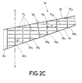
- FIG. 2A shows a preferred embodiment of an horizontal tail plane HTP (8) which is a symmetric structure and comprises first and second lateral torsion boxes (1 a,1 b) joined to each other at a central region of the HTP, and symmetrically arranged with respect to the axis of symmetry (X) of the HTP.
- Each of said lateral torsion boxes (1 a,1 b) is formed by front and rear spars (2a,3a,2b,3b), and a plurality of ribs (4a,4b) having ends joined to the respective front and rear spars (2a,3a,2b,3b).
- Upper and lower skin covers (11a,11b) are supported by the torsion box, and are stiffened by a plurality of stringers (7a,7b) longitudinally arranged and fixed respectively to internal surfaces of the covers.
- a group of ribs (4a,4b) (preferably, the majority of the ribs of the HTP), are parallel to the plane of symmetry (X) of the horizontal tail plane, as shown more clearly in figure 2A .
- the stringers (7a,7b) are arranged as to define an angle ( ⁇ ) within the range (80°-100°) (in top plan view) with respect to the plane of symmetry (X) of the horizontal tail plane (8).
- the stringers (7a,7b) are not continuous through ribs (4a,4b), but stringers (7a,7b) are terminated between consecutive ribs. As shown more clearly in figure 4 , each stringer is conventionally terminated with run-outs sections (12).
- each stringer is placed between two consecutive ribs, and wherein each stringer is shorter or equal than the distance (d) between the two consecutive ribs within which that stringer is placed.
- the stringer (7b1) is placed or is terminated between consecutive ribs (4b6) and (4b7), and therefore the stringer (7b1) is shorter than said distance (d).
- the same configuration is repeated for most of the other stringers of the HTP.
- the stringer is much shorter than said distance (d) and one of its ends is near the rear spar (3b).
- the horizontal tail plane further comprises ribs placed in correspondence with the position of these attachment fittings (9a,9b) at the rear spar, and these ribs are orthogonal to the longitudinal axis of the respective rear spar. This is the case of rib (4b5) in figure 2C , which has an end fixed at a position of the rear spar (3b) wherein the attachment fitting (9b) is located.
- these ribs can be parallel to the plane of symmetry or orthogonal the rear spars.
- the stringers (7a,7b) are grouped in rows of aligned stringers, and the rows are parallel to each other.
- CFRP Carbon Fiber Reinforced Plastic
- the optimized HTP structure of the invention significantly simplifies the manufacturing and assembly process, since the ribs are now easier to manufacture to the absence of mouse holes (as well as the associated tooling), and there is no interference between ribs and stringers.
Landscapes
- Engineering & Computer Science (AREA)
- Aviation & Aerospace Engineering (AREA)
- Mechanical Engineering (AREA)
- Moulding By Coating Moulds (AREA)
Abstract

Description
- The present invention refers in general to aircraft primary structures formed with multi-rib torsion boxes, and manufactured mainly with composite materials, such as Carbon Fiber Reinforced Plastic (CFRP).
- More specifically, an object of the invention is to provide an aircraft horizontal tail plane (HTP) having a multi-rib torsion box, which can be assembled and manufactured easier and faster than traditional HTP designs.
- A known structure of a horizontal tail plane (HTP) of an aircraft is shown in
figure 1 , and comprises a multi-rib torsion box (1) formed by front and rear spars (2,3) and a plurality of ribs (4) transversally arranged and fitted to front and rear spars as to form together a box-like configuration. As it can be noted infigure 1 , the ribs are obliquely arranged with respect to the plane of symmetry of the HTP. - The ribs provide torsional rigidity and support local load introductions resulting from actuator fittings, pivot fittings, support bearings etc., which are directly secured to the front and rear ribs.
- Other components of the HTP such as leading and trailing edges (5,6), are assembled with the torsion box (1). Elevators are control surfaces of the aircraft and are hinged to the torsion box, which is the structural component of the HTP and as such, it has to withstand the loads to which the HTP is subjected.
- An HTP torsion box of the continuous type is formed by two lateral torsion boxes (right-hand side and left-hand side torsion box) joined to each other at the central region of the HTP, and are symmetrically arranged with respect to the plane of symmetry of the horizontal tail plane.
- The torsion box also includes upper and lower skin panels internally reinforced by stringers extending longitudinally. Two arrangement patterns and configurations are typically used for the stringers distribution.
Figure 1A shows a first known pattern, wherein the stringers (7) are parallel to each other, are continuous through the ribs (4) and are provided with run-outs sections to avoid interference with the ribs. -
Figure 1B shows a second known pattern, wherein the stringers (7) are arranged in a conical configuration converging towards a tip of the respective torsion box. In this second case the stringers are continuous in the entire length of the torsion box, thus no run-outs are needed. - In these two cases and due to the continuity of the stringers, the stringers interfere with the ribs, such as the ribs have to be designed and manufactured to solve the intersection between these two structural elements. For this reason, the ribs have to be manufactured with the so-called "mouse holes" in order to accommodate several stringers extending through the rib.
- This known ribs configuration with mouse holes is shown for example in figure 9 of the European patent
EP-2.851.283 A1 . - However, the manufacture of this type of ribs with mouse holes is a difficult task and requires specific tooling which is also difficult to manufacture. Furthermore, the assembly of the torsion box components, is time-consuming since the stringers have to be received precisely and bonded in the respective mouse holes of the ribs.
- The present invention is defined in the attached independent claim and it overcomes the above-mentioned drawbacks of the prior art, by providing a horizontal tail plane (HTP) having a multi-rib torsion box which assembly and manufacturing process are simplified compared with traditional HTP designs.
- Therefore, an aspect of the invention refers to a horizontal tail plane for an aircraft, conventionally comprising first and second lateral torsion boxes joined to each other at a central region of the HTP, and symmetrically arranged with respect to the plane of symmetry of the horizontal tail plane.
- Each of said lateral torsion boxes comprises front and rear spars, and a plurality of ribs having ends respectively joined to the front and rear spars. Upper and lower skin covers are fixed to the torsion box, and are provided with a plurality of stringers internally fixed to one of the covers.
- According to the invention, a group of ribs are arranged substantially parallel to the plane of symmetry of the horizontal tail plane. Additionally, the stringers are arranged as to define an angle within the range (80°-100°) with respect to the plane of symmetry of the horizontal tail plane. It has been found, that this stringer distribution is optimum to react to torsional moments which appear at the torsion box.
- Since the stringers orientation is (+/- 10°) perpendicular to the plane of symmetry, and the ribs are parallel to that plane of symmetry, it results that ribs and stringers are generally orthogonal to each other.
- Due to this relative arrangement between ribs and stringers, the stringers no need to be continuous through ribs, thus each stringers extend only between two consecutive ribs. Therefore, the ribs can be manufactured without mouse holes, such as their manufacturing process is simplified.
- In this way, the majority of the HTP stringers are dimensioned such as each stringer has a length shorter or equal than the distance between the two consecutive ribs within which that stringer is placed.
- Additionally, some ribs of the horizontal tail plane are orthogonal to the longitudinal axis of the respective rear spar, and are placed in correspondence with an attachment fittings secured to the rear spar. Since these attachment fittings are highly loaded areas of the HTP, this orthogonal ribs enhance loads introduction from the fittings.
- Some of the main advantages of the invention are:
- optimized stringers arrangement to react more efficiently to torsion moments,
- combination of ribs parallel to plane of symmetry and ribs orthogonal to rear spars,
- non-continuous stringers through ribs, eliminate mouse holes in ribs,
- minimize assembly and manufacturing time compared with prior art HTP concepts.
- Preferred embodiments of the invention, are henceforth described with reference to the accompanying drawings, wherein:
-
Figure 1 .- shows in top plan view one of the two torsion boxes of a horizontal tail plane, and the traditional layout of the continuous stringers according to the prior art, whereinfigure 1A shows a traditional parallel pattern andfigure 1B shows a traditional conical pattern. -
Figure 2 .- shows two schematic representations in top plan view of a torsion box of a horizontal tail plane according to the invention, whereinfigure 2A shows only the ribs layout,figure 3B shows the stringers layout in addition to the ribs, andfigure 2C is an enlarged detail of the encircled area infigure 2B . -
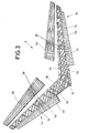
Figure 3 .- shows a perspective view of an horizontal tail plane according to the invention. -
Figure 4 .- shows a schematic representation in an elevational view of a torsion box according to the invention. -
Figure 2A shows a preferred embodiment of an horizontal tail plane HTP (8) which is a symmetric structure and comprises first and second lateral torsion boxes (1 a,1 b) joined to each other at a central region of the HTP, and symmetrically arranged with respect to the axis of symmetry (X) of the HTP. Each of said lateral torsion boxes (1 a,1 b) is formed by front and rear spars (2a,3a,2b,3b), and a plurality of ribs (4a,4b) having ends joined to the respective front and rear spars (2a,3a,2b,3b). - Upper and lower skin covers (11a,11b) are supported by the torsion box, and are stiffened by a plurality of stringers (7a,7b) longitudinally arranged and fixed respectively to internal surfaces of the covers.
- According to the invention, a group of ribs (4a,4b) (preferably, the majority of the ribs of the HTP), are parallel to the plane of symmetry (X) of the horizontal tail plane, as shown more clearly in
figure 2A . Furthermore, the stringers (7a,7b) are arranged as to define an angle (α) within the range (80°-100°) (in top plan view) with respect to the plane of symmetry (X) of the horizontal tail plane (8). - Unlike traditional designs, according to the invention the stringers (7a,7b) are not continuous through ribs (4a,4b), but stringers (7a,7b) are terminated between consecutive ribs. As shown more clearly in
figure 4 , each stringer is conventionally terminated with run-outs sections (12). - In other words, each stringer is placed between two consecutive ribs, and wherein each stringer is shorter or equal than the distance (d) between the two consecutive ribs within which that stringer is placed. For example, in the enlarged views of
figures 2C and4 , the stringer (7b1) is placed or is terminated between consecutive ribs (4b6) and (4b7), and therefore the stringer (7b1) is shorter than said distance (d). The same configuration is repeated for most of the other stringers of the HTP. - In some cases, for example in the case of stringer (7b2), the stringer is much shorter than said distance (d) and one of its ends is near the rear spar (3b).
- Conventionally, in this horizontal tail planes of the continuous type, some attachment fittings (9a,9b) are secured to the rear spars for the attachment of actuator fittings, pivot fittings, support bearings etc. At the front part of the HTP, a front fitting (10) is provided to receive a trimming actuator (not shown) for the HTP.
- The horizontal tail plane further comprises ribs placed in correspondence with the position of these attachment fittings (9a,9b) at the rear spar, and these ribs are orthogonal to the longitudinal axis of the respective rear spar. This is the case of rib (4b5) in
figure 2C , which has an end fixed at a position of the rear spar (3b) wherein the attachment fitting (9b) is located. - In the case of the inner-most ribs (4a0,4b0), that is, the ribs closer to the plane of symmetry (X), these ribs can be parallel to the plane of symmetry or orthogonal the rear spars.
- As it can be noted in
figures 2B ,2C , the stringers (7a,7b) are grouped in rows of aligned stringers, and the rows are parallel to each other. - Most of the components of the HTP are manufactured with composite materials, preferably Carbon Fiber Reinforced Plastic (CFRP) materials, by means of any know manufacturing process or combination thereof associated to these materials.
- The optimized HTP structure of the invention, significantly simplifies the manufacturing and assembly process, since the ribs are now easier to manufacture to the absence of mouse holes (as well as the associated tooling), and there is no interference between ribs and stringers.
Claims (5)
- Horizontal tail plane for an aircraft, the horizontal tail plane comprising:first and second lateral torsion boxes joined to each other at a central region thereof and symmetrically arranged with respect to a plane of symmetry of the horizontal tail plane,wherein each of said lateral torsion boxes comprises front and rear spars, and a plurality of ribs having ends respectively joined to the front and rear spars,upper and lower covers having a plurality of stringers internally fixed thereto,characterized in that a group of ribs are substantially parallel to the plane of symmetry of the horizontal tail plane,and wherein said the stringers are arranged as to define an angle within the range (80°-100°) with respect to the plane of symmetry of the horizontal tail plane,and wherein the stringers are placed between two consecutive ribs, and wherein each stringer is shorter than the distance between the two consecutive ribs within which that stringer is placed.
- Horizontal tail plane according to claim 1 wherein the stringers are grouped in rows of aligned stringers, and the rows are parallel to each other.
- Horizontal tail plane according to claim 1 or 2 wherein a group of stringers extends between a rib and a rear or front spar.
- Horizontal tail plane according to any of the preceding claims wherein the rear spars have attachment fittings, and wherein the horizontal tail plane further comprises ribs orthogonally arranged with respect to the longitudinal axis of the respective rear spar and placed in correspondence with an attachment fitting.
- Horizontal tail plane according to any of the preceding claims obtained from a composite material.
Priority Applications (3)
| Application Number | Priority Date | Filing Date | Title |
|---|---|---|---|
| EP15382231.7A EP3090940B1 (en) | 2015-05-05 | 2015-05-05 | Horizontal tail plane with a multi-rib torsion box |
| ES15382231.7T ES2661888T3 (en) | 2015-05-05 | 2015-05-05 | Horizontal glue plane with a multi-rib torsion box |
| US15/147,202 US20160325822A1 (en) | 2015-05-05 | 2016-05-05 | Horizontal tail plane with a multi-rib torsion box |
Applications Claiming Priority (1)
| Application Number | Priority Date | Filing Date | Title |
|---|---|---|---|
| EP15382231.7A EP3090940B1 (en) | 2015-05-05 | 2015-05-05 | Horizontal tail plane with a multi-rib torsion box |
Publications (2)
| Publication Number | Publication Date |
|---|---|
| EP3090940A1 true EP3090940A1 (en) | 2016-11-09 |
| EP3090940B1 EP3090940B1 (en) | 2017-12-06 |
Family
ID=53180689
Family Applications (1)
| Application Number | Title | Priority Date | Filing Date |
|---|---|---|---|
| EP15382231.7A Not-in-force EP3090940B1 (en) | 2015-05-05 | 2015-05-05 | Horizontal tail plane with a multi-rib torsion box |
Country Status (3)
| Country | Link |
|---|---|
| US (1) | US20160325822A1 (en) |
| EP (1) | EP3090940B1 (en) |
| ES (1) | ES2661888T3 (en) |
Families Citing this family (5)
| Publication number | Priority date | Publication date | Assignee | Title |
|---|---|---|---|---|
| EP2886450B1 (en) * | 2013-12-23 | 2019-09-18 | Airbus Operations S.L. | Aircraft control surface |
| ES2715552T3 (en) * | 2016-03-14 | 2019-06-04 | Airbus Operations Sl | Airframe section incorporating a dynamic cable collector |
| GB2563422A (en) * | 2017-06-15 | 2018-12-19 | Airbus Operations Ltd | A spar arrangement in a wing tip device |
| CN109606622A (en) * | 2018-11-07 | 2019-04-12 | 中国航空工业集团公司西安飞机设计研究所 | A design method for integrally bonded composite movable surface reinforced wall panels |
| US11319051B2 (en) * | 2020-01-03 | 2022-05-03 | The Boeing Company | Stiffened composite ribs |
Citations (3)
| Publication number | Priority date | Publication date | Assignee | Title |
|---|---|---|---|---|
| US2378885A (en) * | 1943-03-06 | 1945-06-19 | Budd Edward G Mfg Co | Empennage construction and mounting |
| WO2008037847A1 (en) * | 2006-09-26 | 2008-04-03 | Patria Aerostructures Oy | Curved element, wing, control surface and stabilizer for aircraft |
| EP2851283A1 (en) | 2013-09-23 | 2015-03-25 | Airbus Operations S.L. | Method for manufacturing an aeronautical torsion box, torsion box and tool for manufacturing an aeronautical torsion box |
-
2015
- 2015-05-05 EP EP15382231.7A patent/EP3090940B1/en not_active Not-in-force
- 2015-05-05 ES ES15382231.7T patent/ES2661888T3/en active Active
-
2016
- 2016-05-05 US US15/147,202 patent/US20160325822A1/en not_active Abandoned
Patent Citations (3)
| Publication number | Priority date | Publication date | Assignee | Title |
|---|---|---|---|---|
| US2378885A (en) * | 1943-03-06 | 1945-06-19 | Budd Edward G Mfg Co | Empennage construction and mounting |
| WO2008037847A1 (en) * | 2006-09-26 | 2008-04-03 | Patria Aerostructures Oy | Curved element, wing, control surface and stabilizer for aircraft |
| EP2851283A1 (en) | 2013-09-23 | 2015-03-25 | Airbus Operations S.L. | Method for manufacturing an aeronautical torsion box, torsion box and tool for manufacturing an aeronautical torsion box |
Also Published As
| Publication number | Publication date |
|---|---|
| ES2661888T3 (en) | 2018-04-04 |
| US20160325822A1 (en) | 2016-11-10 |
| EP3090940B1 (en) | 2017-12-06 |
Similar Documents
| Publication | Publication Date | Title |
|---|---|---|
| EP3090940B1 (en) | Horizontal tail plane with a multi-rib torsion box | |
| EP2848519B1 (en) | Upper joints between outboard wing boxes and wing center sections of aircraft wing assemblies | |
| KR102066754B1 (en) | Vertically integrated stringers | |
| CN106335629B (en) | Fuselage spar structure with continuous integral fastened upper and lower chord sections | |
| EP3150484B1 (en) | Composite rib for an aircraft torsion box and manufacturing method thereof | |
| CN105523166B (en) | Plate structure and related methods | |
| US10239602B2 (en) | Multi-spar torsion box structure | |
| US20100133382A1 (en) | Wing-fuselage section of an aircraft | |
| ES2606245T3 (en) | Highly integrated leading edge of a supporting surface of an aircraft | |
| EP2810869B1 (en) | Lower joints between outboard wing boxes and center wing sections of aircraft wing assemblies | |
| EP3040263B1 (en) | Tail cone of an aircraft | |
| EP2671793B1 (en) | Torsion box for an aircraft stiffened with non-parallel stringers | |
| KR20100106623A (en) | Fuselage structure for airplane | |
| ES2584557T3 (en) | Highly integrated internal structure of a torsion box of a supporting surface of an aircraft and method for its production | |
| EP2886450B1 (en) | Aircraft control surface | |
| US9010688B2 (en) | Structural joint having continuous skin with inside and outside stringers | |
| EP2540618B1 (en) | Filler panel for bulkhead to skin joint in integral tanks | |
| EP3040268A1 (en) | Stringer stiffened aircraft composite structures | |
| EP3015361A1 (en) | Central area arrangement for continuous horizontal tail plane torsion box | |
| EP2593360B1 (en) | Beam for an aircraft fuselage floor | |
| EP2457823B1 (en) | An aircraft lifting surface skin | |
| US20150183508A1 (en) | Horizontal tail plane of an aircraft | |
| EP3401207A1 (en) | Systems and methods for aircraft integrated composite frames | |
| EP3181454A1 (en) | Aircraft pylon assembly |
Legal Events
| Date | Code | Title | Description |
|---|---|---|---|
| PUAI | Public reference made under article 153(3) epc to a published international application that has entered the european phase |
Free format text: ORIGINAL CODE: 0009012 |
|
| AK | Designated contracting states |
Kind code of ref document: A1 Designated state(s): AL AT BE BG CH CY CZ DE DK EE ES FI FR GB GR HR HU IE IS IT LI LT LU LV MC MK MT NL NO PL PT RO RS SE SI SK SM TR |
|
| AX | Request for extension of the european patent |
Extension state: BA ME |
|
| STAA | Information on the status of an ep patent application or granted ep patent |
Free format text: STATUS: REQUEST FOR EXAMINATION WAS MADE |
|
| 17P | Request for examination filed |
Effective date: 20170503 |
|
| RBV | Designated contracting states (corrected) |
Designated state(s): AL AT BE BG CH CY CZ DE DK EE ES FI FR GB GR HR HU IE IS IT LI LT LU LV MC MK MT NL NO PL PT RO RS SE SI SK SM TR |
|
| GRAP | Despatch of communication of intention to grant a patent |
Free format text: ORIGINAL CODE: EPIDOSNIGR1 |
|
| STAA | Information on the status of an ep patent application or granted ep patent |
Free format text: STATUS: GRANT OF PATENT IS INTENDED |
|
| RIC1 | Information provided on ipc code assigned before grant |
Ipc: B64C 3/18 20060101AFI20170518BHEP Ipc: B64C 5/02 20060101ALI20170518BHEP |
|
| INTG | Intention to grant announced |
Effective date: 20170619 |
|
| GRAS | Grant fee paid |
Free format text: ORIGINAL CODE: EPIDOSNIGR3 |
|
| GRAA | (expected) grant |
Free format text: ORIGINAL CODE: 0009210 |
|
| STAA | Information on the status of an ep patent application or granted ep patent |
Free format text: STATUS: THE PATENT HAS BEEN GRANTED |
|
| AK | Designated contracting states |
Kind code of ref document: B1 Designated state(s): AL AT BE BG CH CY CZ DE DK EE ES FI FR GB GR HR HU IE IS IT LI LT LU LV MC MK MT NL NO PL PT RO RS SE SI SK SM TR |
|
| REG | Reference to a national code |
Ref country code: GB Ref legal event code: FG4D |
|
| REG | Reference to a national code |
Ref country code: AT Ref legal event code: REF Ref document number: 952133 Country of ref document: AT Kind code of ref document: T Effective date: 20171215 Ref country code: CH Ref legal event code: EP |
|
| REG | Reference to a national code |
Ref country code: IE Ref legal event code: FG4D |
|
| REG | Reference to a national code |
Ref country code: DE Ref legal event code: R096 Ref document number: 602015006496 Country of ref document: DE |
|
| REG | Reference to a national code |
Ref country code: ES Ref legal event code: FG2A Ref document number: 2661888 Country of ref document: ES Kind code of ref document: T3 Effective date: 20180404 |
|
| REG | Reference to a national code |
Ref country code: NL Ref legal event code: MP Effective date: 20171206 |
|
| REG | Reference to a national code |
Ref country code: LT Ref legal event code: MG4D |
|
| PG25 | Lapsed in a contracting state [announced via postgrant information from national office to epo] |
Ref country code: NO Free format text: LAPSE BECAUSE OF FAILURE TO SUBMIT A TRANSLATION OF THE DESCRIPTION OR TO PAY THE FEE WITHIN THE PRESCRIBED TIME-LIMIT Effective date: 20180306 Ref country code: LT Free format text: LAPSE BECAUSE OF FAILURE TO SUBMIT A TRANSLATION OF THE DESCRIPTION OR TO PAY THE FEE WITHIN THE PRESCRIBED TIME-LIMIT Effective date: 20171206 Ref country code: SE Free format text: LAPSE BECAUSE OF FAILURE TO SUBMIT A TRANSLATION OF THE DESCRIPTION OR TO PAY THE FEE WITHIN THE PRESCRIBED TIME-LIMIT Effective date: 20171206 Ref country code: FI Free format text: LAPSE BECAUSE OF FAILURE TO SUBMIT A TRANSLATION OF THE DESCRIPTION OR TO PAY THE FEE WITHIN THE PRESCRIBED TIME-LIMIT Effective date: 20171206 |
|
| REG | Reference to a national code |
Ref country code: AT Ref legal event code: MK05 Ref document number: 952133 Country of ref document: AT Kind code of ref document: T Effective date: 20171206 |
|
| REG | Reference to a national code |
Ref country code: FR Ref legal event code: PLFP Year of fee payment: 4 |
|
| PG25 | Lapsed in a contracting state [announced via postgrant information from national office to epo] |
Ref country code: BG Free format text: LAPSE BECAUSE OF FAILURE TO SUBMIT A TRANSLATION OF THE DESCRIPTION OR TO PAY THE FEE WITHIN THE PRESCRIBED TIME-LIMIT Effective date: 20180306 Ref country code: HR Free format text: LAPSE BECAUSE OF FAILURE TO SUBMIT A TRANSLATION OF THE DESCRIPTION OR TO PAY THE FEE WITHIN THE PRESCRIBED TIME-LIMIT Effective date: 20171206 Ref country code: GR Free format text: LAPSE BECAUSE OF FAILURE TO SUBMIT A TRANSLATION OF THE DESCRIPTION OR TO PAY THE FEE WITHIN THE PRESCRIBED TIME-LIMIT Effective date: 20180307 Ref country code: RS Free format text: LAPSE BECAUSE OF FAILURE TO SUBMIT A TRANSLATION OF THE DESCRIPTION OR TO PAY THE FEE WITHIN THE PRESCRIBED TIME-LIMIT Effective date: 20171206 Ref country code: LV Free format text: LAPSE BECAUSE OF FAILURE TO SUBMIT A TRANSLATION OF THE DESCRIPTION OR TO PAY THE FEE WITHIN THE PRESCRIBED TIME-LIMIT Effective date: 20171206 |
|
| PG25 | Lapsed in a contracting state [announced via postgrant information from national office to epo] |
Ref country code: NL Free format text: LAPSE BECAUSE OF FAILURE TO SUBMIT A TRANSLATION OF THE DESCRIPTION OR TO PAY THE FEE WITHIN THE PRESCRIBED TIME-LIMIT Effective date: 20171206 |
|
| PG25 | Lapsed in a contracting state [announced via postgrant information from national office to epo] |
Ref country code: EE Free format text: LAPSE BECAUSE OF FAILURE TO SUBMIT A TRANSLATION OF THE DESCRIPTION OR TO PAY THE FEE WITHIN THE PRESCRIBED TIME-LIMIT Effective date: 20171206 Ref country code: CZ Free format text: LAPSE BECAUSE OF FAILURE TO SUBMIT A TRANSLATION OF THE DESCRIPTION OR TO PAY THE FEE WITHIN THE PRESCRIBED TIME-LIMIT Effective date: 20171206 Ref country code: SK Free format text: LAPSE BECAUSE OF FAILURE TO SUBMIT A TRANSLATION OF THE DESCRIPTION OR TO PAY THE FEE WITHIN THE PRESCRIBED TIME-LIMIT Effective date: 20171206 |
|
| PGFP | Annual fee paid to national office [announced via postgrant information from national office to epo] |
Ref country code: ES Payment date: 20180626 Year of fee payment: 4 Ref country code: DE Payment date: 20180522 Year of fee payment: 4 |
|
| PG25 | Lapsed in a contracting state [announced via postgrant information from national office to epo] |
Ref country code: AT Free format text: LAPSE BECAUSE OF FAILURE TO SUBMIT A TRANSLATION OF THE DESCRIPTION OR TO PAY THE FEE WITHIN THE PRESCRIBED TIME-LIMIT Effective date: 20171206 Ref country code: SM Free format text: LAPSE BECAUSE OF FAILURE TO SUBMIT A TRANSLATION OF THE DESCRIPTION OR TO PAY THE FEE WITHIN THE PRESCRIBED TIME-LIMIT Effective date: 20171206 Ref country code: IT Free format text: LAPSE BECAUSE OF FAILURE TO SUBMIT A TRANSLATION OF THE DESCRIPTION OR TO PAY THE FEE WITHIN THE PRESCRIBED TIME-LIMIT Effective date: 20171206 Ref country code: PL Free format text: LAPSE BECAUSE OF FAILURE TO SUBMIT A TRANSLATION OF THE DESCRIPTION OR TO PAY THE FEE WITHIN THE PRESCRIBED TIME-LIMIT Effective date: 20171206 |
|
| PGFP | Annual fee paid to national office [announced via postgrant information from national office to epo] |
Ref country code: FR Payment date: 20180522 Year of fee payment: 4 |
|
| REG | Reference to a national code |
Ref country code: DE Ref legal event code: R097 Ref document number: 602015006496 Country of ref document: DE |
|
| PLBE | No opposition filed within time limit |
Free format text: ORIGINAL CODE: 0009261 |
|
| STAA | Information on the status of an ep patent application or granted ep patent |
Free format text: STATUS: NO OPPOSITION FILED WITHIN TIME LIMIT |
|
| 26N | No opposition filed |
Effective date: 20180907 |
|
| PG25 | Lapsed in a contracting state [announced via postgrant information from national office to epo] |
Ref country code: DK Free format text: LAPSE BECAUSE OF FAILURE TO SUBMIT A TRANSLATION OF THE DESCRIPTION OR TO PAY THE FEE WITHIN THE PRESCRIBED TIME-LIMIT Effective date: 20171206 Ref country code: SI Free format text: LAPSE BECAUSE OF FAILURE TO SUBMIT A TRANSLATION OF THE DESCRIPTION OR TO PAY THE FEE WITHIN THE PRESCRIBED TIME-LIMIT Effective date: 20171206 |
|
| REG | Reference to a national code |
Ref country code: CH Ref legal event code: PL |
|
| REG | Reference to a national code |
Ref country code: BE Ref legal event code: MM Effective date: 20180531 |
|
| PG25 | Lapsed in a contracting state [announced via postgrant information from national office to epo] |
Ref country code: MC Free format text: LAPSE BECAUSE OF FAILURE TO SUBMIT A TRANSLATION OF THE DESCRIPTION OR TO PAY THE FEE WITHIN THE PRESCRIBED TIME-LIMIT Effective date: 20171206 |
|
| REG | Reference to a national code |
Ref country code: IE Ref legal event code: MM4A |
|
| PG25 | Lapsed in a contracting state [announced via postgrant information from national office to epo] |
Ref country code: CH Free format text: LAPSE BECAUSE OF NON-PAYMENT OF DUE FEES Effective date: 20180531 Ref country code: LI Free format text: LAPSE BECAUSE OF NON-PAYMENT OF DUE FEES Effective date: 20180531 |
|
| PG25 | Lapsed in a contracting state [announced via postgrant information from national office to epo] |
Ref country code: LU Free format text: LAPSE BECAUSE OF NON-PAYMENT OF DUE FEES Effective date: 20180505 |
|
| PG25 | Lapsed in a contracting state [announced via postgrant information from national office to epo] |
Ref country code: IE Free format text: LAPSE BECAUSE OF NON-PAYMENT OF DUE FEES Effective date: 20180505 |
|
| PG25 | Lapsed in a contracting state [announced via postgrant information from national office to epo] |
Ref country code: BE Free format text: LAPSE BECAUSE OF NON-PAYMENT OF DUE FEES Effective date: 20180531 |
|
| REG | Reference to a national code |
Ref country code: DE Ref legal event code: R119 Ref document number: 602015006496 Country of ref document: DE |
|
| GBPC | Gb: european patent ceased through non-payment of renewal fee |
Effective date: 20190505 |
|
| PG25 | Lapsed in a contracting state [announced via postgrant information from national office to epo] |
Ref country code: MT Free format text: LAPSE BECAUSE OF NON-PAYMENT OF DUE FEES Effective date: 20180505 |
|
| PG25 | Lapsed in a contracting state [announced via postgrant information from national office to epo] |
Ref country code: TR Free format text: LAPSE BECAUSE OF FAILURE TO SUBMIT A TRANSLATION OF THE DESCRIPTION OR TO PAY THE FEE WITHIN THE PRESCRIBED TIME-LIMIT Effective date: 20171206 |
|
| PG25 | Lapsed in a contracting state [announced via postgrant information from national office to epo] |
Ref country code: GB Free format text: LAPSE BECAUSE OF NON-PAYMENT OF DUE FEES Effective date: 20190505 Ref country code: DE Free format text: LAPSE BECAUSE OF NON-PAYMENT OF DUE FEES Effective date: 20191203 |
|
| PG25 | Lapsed in a contracting state [announced via postgrant information from national office to epo] |
Ref country code: PT Free format text: LAPSE BECAUSE OF FAILURE TO SUBMIT A TRANSLATION OF THE DESCRIPTION OR TO PAY THE FEE WITHIN THE PRESCRIBED TIME-LIMIT Effective date: 20171206 |
|
| PG25 | Lapsed in a contracting state [announced via postgrant information from national office to epo] |
Ref country code: FR Free format text: LAPSE BECAUSE OF NON-PAYMENT OF DUE FEES Effective date: 20190531 Ref country code: MK Free format text: LAPSE BECAUSE OF NON-PAYMENT OF DUE FEES Effective date: 20171206 Ref country code: CY Free format text: LAPSE BECAUSE OF FAILURE TO SUBMIT A TRANSLATION OF THE DESCRIPTION OR TO PAY THE FEE WITHIN THE PRESCRIBED TIME-LIMIT Effective date: 20171206 Ref country code: HU Free format text: LAPSE BECAUSE OF FAILURE TO SUBMIT A TRANSLATION OF THE DESCRIPTION OR TO PAY THE FEE WITHIN THE PRESCRIBED TIME-LIMIT; INVALID AB INITIO Effective date: 20150505 Ref country code: RO Free format text: LAPSE BECAUSE OF FAILURE TO SUBMIT A TRANSLATION OF THE DESCRIPTION OR TO PAY THE FEE WITHIN THE PRESCRIBED TIME-LIMIT Effective date: 20171206 |
|
| PG25 | Lapsed in a contracting state [announced via postgrant information from national office to epo] |
Ref country code: AL Free format text: LAPSE BECAUSE OF FAILURE TO SUBMIT A TRANSLATION OF THE DESCRIPTION OR TO PAY THE FEE WITHIN THE PRESCRIBED TIME-LIMIT Effective date: 20171206 Ref country code: IS Free format text: LAPSE BECAUSE OF FAILURE TO SUBMIT A TRANSLATION OF THE DESCRIPTION OR TO PAY THE FEE WITHIN THE PRESCRIBED TIME-LIMIT Effective date: 20180406 |
|
| REG | Reference to a national code |
Ref country code: ES Ref legal event code: FD2A Effective date: 20200925 |
|
| PG25 | Lapsed in a contracting state [announced via postgrant information from national office to epo] |
Ref country code: ES Free format text: LAPSE BECAUSE OF NON-PAYMENT OF DUE FEES Effective date: 20190506 |