EP3090919A1 - Service plan creation device - Google Patents
Service plan creation device Download PDFInfo
- Publication number
- EP3090919A1 EP3090919A1 EP14871246.6A EP14871246A EP3090919A1 EP 3090919 A1 EP3090919 A1 EP 3090919A1 EP 14871246 A EP14871246 A EP 14871246A EP 3090919 A1 EP3090919 A1 EP 3090919A1
- Authority
- EP
- European Patent Office
- Prior art keywords
- run
- inter
- operation plan
- stop
- curve
- Prior art date
- Legal status (The legal status is an assumption and is not a legal conclusion. Google has not performed a legal analysis and makes no representation as to the accuracy of the status listed.)
- Granted
Links
Images



Classifications
-
- B—PERFORMING OPERATIONS; TRANSPORTING
- B60—VEHICLES IN GENERAL
- B60L—PROPULSION OF ELECTRICALLY-PROPELLED VEHICLES; SUPPLYING ELECTRIC POWER FOR AUXILIARY EQUIPMENT OF ELECTRICALLY-PROPELLED VEHICLES; ELECTRODYNAMIC BRAKE SYSTEMS FOR VEHICLES IN GENERAL; MAGNETIC SUSPENSION OR LEVITATION FOR VEHICLES; MONITORING OPERATING VARIABLES OF ELECTRICALLY-PROPELLED VEHICLES; ELECTRIC SAFETY DEVICES FOR ELECTRICALLY-PROPELLED VEHICLES
- B60L15/00—Methods, circuits, or devices for controlling the traction-motor speed of electrically-propelled vehicles
- B60L15/40—Adaptation of control equipment on vehicle for remote actuation from a stationary place
-
- B—PERFORMING OPERATIONS; TRANSPORTING
- B60—VEHICLES IN GENERAL
- B60L—PROPULSION OF ELECTRICALLY-PROPELLED VEHICLES; SUPPLYING ELECTRIC POWER FOR AUXILIARY EQUIPMENT OF ELECTRICALLY-PROPELLED VEHICLES; ELECTRODYNAMIC BRAKE SYSTEMS FOR VEHICLES IN GENERAL; MAGNETIC SUSPENSION OR LEVITATION FOR VEHICLES; MONITORING OPERATING VARIABLES OF ELECTRICALLY-PROPELLED VEHICLES; ELECTRIC SAFETY DEVICES FOR ELECTRICALLY-PROPELLED VEHICLES
- B60L2200/00—Type of vehicles
- B60L2200/26—Rail vehicles
-
- B—PERFORMING OPERATIONS; TRANSPORTING
- B60—VEHICLES IN GENERAL
- B60L—PROPULSION OF ELECTRICALLY-PROPELLED VEHICLES; SUPPLYING ELECTRIC POWER FOR AUXILIARY EQUIPMENT OF ELECTRICALLY-PROPELLED VEHICLES; ELECTRODYNAMIC BRAKE SYSTEMS FOR VEHICLES IN GENERAL; MAGNETIC SUSPENSION OR LEVITATION FOR VEHICLES; MONITORING OPERATING VARIABLES OF ELECTRICALLY-PROPELLED VEHICLES; ELECTRIC SAFETY DEVICES FOR ELECTRICALLY-PROPELLED VEHICLES
- B60L2240/00—Control parameters of input or output; Target parameters
- B60L2240/80—Time limits
-
- B—PERFORMING OPERATIONS; TRANSPORTING
- B60—VEHICLES IN GENERAL
- B60L—PROPULSION OF ELECTRICALLY-PROPELLED VEHICLES; SUPPLYING ELECTRIC POWER FOR AUXILIARY EQUIPMENT OF ELECTRICALLY-PROPELLED VEHICLES; ELECTRODYNAMIC BRAKE SYSTEMS FOR VEHICLES IN GENERAL; MAGNETIC SUSPENSION OR LEVITATION FOR VEHICLES; MONITORING OPERATING VARIABLES OF ELECTRICALLY-PROPELLED VEHICLES; ELECTRIC SAFETY DEVICES FOR ELECTRICALLY-PROPELLED VEHICLES
- B60L2250/00—Driver interactions
- B60L2250/16—Driver interactions by display
Definitions
- Embodiments of the present invention relate to an operation plan creation device.
- An operation plan creation device comprises a storage unit and an operation plan creation unit.
- the storage unit is configured to store therein route information, operation information, and car information.
- the operation plan creation unit comprises an operation plan condition setting module, a run-curve condition setting module, a run-curve creation module, and an operation plan creation module.
- the operation plan condition setting module is configured to receive car type information, operation type information, operation section information, and a total run time length from a starting station to a destination station, through an input device.
- the run-curve condition setting module is configured: to retrieve the storage unit based on the operation type information and the operation section information received by the operation plan condition setting module; to identify stop stations to set inter-stop sections for which run-curves are to be created; and to set run time lengths between the stop stations based on an input from the input device.
- the run-curve creation module is configured: to retrieve the storage unit to extract the route information and the car information based on the car type information and the operation section information received by the operation plan condition setting module; to acquire a first run-curve and a first energy consumption in each of the inter-stop sections based on the extracted route information and car information and the inter-stop sections set by the run-curve condition setting module; to correct, when a total extension time length is set, the run time lengths set by the run-curve condition setting module based on the total extension time length; and to acquire a second run-curve based on the corrected run time lengths.
- the operation plan creation module is configured: to acquire the total extension time length based on the total run time length, the run time lengths in the inter-stop sections, and stoppage time lengths included in the operation information stored in the storage unit; to notify the run-curve creation module of the acquired total extension time length; and to create an operation plan based on the second run-curve.
- the operation plan creation device 100 includes a creation device main unit 10, an input device 51, a display device 52, and a database 53.
- the database 53 is an example of a "storage unit”.
- the creation device main unit 10 mainly includes an operation plan creation unit 11 and an interface 16.
- the input device 51, the display device 52, and the database 53 are connected to the creation device main unit 10 through the interface 16.
- the operation plan creation unit 11 executes various functions, such as an operation plan condition setting function 12, a run-curve condition setting function 13, a run-curve calculating function 14, and an operation plan creating function (extension time allocating function) 15.
- the database 53 is externally connected to the creation device main unit 10.
- the database 53 may be internally installed in the creation device main unit 10.
- the database 53 is connected to the operation plan creation unit 11 through an internal bus instead of through the interface 16 for connecting to external devices.
- the database 53 stores therein various types of data required in calculating a run-curve.
- the data mainly includes route information, operation information, and car information. These pieces of information include the following items.
- the operation plan condition setting function 12 executes a process of setting operation plan conditions based on information that is entered through the input device 51, such as a mouse or a keyboard, or selected from and entered through a selection menu displayed on the display device 52, and is received through the interface 16.
- Examples of the operation plan condition include a car type, an operation type, an operation section, and a total run time length.
- the operation section represents a section from a starting station to a destination station for which a train diagram is created.
- the total run time length represents the run time for which the train travels from the starting station to the destination station.
- the operation plan condition may also include, for example, the voltage of the overhead wire in the operation section, a margin to the speed limitation set in the operation section, and the like.
- the respective standard values are set to the voltage of the overhead wire, the margin, and the like unless corresponding inputs are entered through the input device 51.
- the run-curve condition setting function 13 executes a process of setting the conditions to create a run-curve for inter-stop sections within an operation section (i.e., run-curve conditions). Specifically, the run-curve condition setting function 13 retrieves the database 53 based on the operation section and the operation type set by the operation plan condition setting function 12, and identifies the stop stations corresponding to the operation type among the stations included in the operation section. The run-curve condition setting function 13 then sets, based on the identified stop stations, inter-stop sections for which run-curves are to be created. In other words, the run-curve condition setting function 13 identifies, as a target for which the run-curve is to be created, a section between two stop stations that is adjacent when the stop stations are arranged in the temporal order.
- the run-curve condition setting function 13 also sets, as a run-curve condition, run time lengths for which the train runs across each of the inter-stop sections included in the operation section as well as the inter-stop sections for which the run-curves are to be created.
- run-curve condition setting function 13 does not set any run time length as a run-curve condition.
- the run-curve calculating function 14 retrieves the database 53 based on the information of the car type and the operation section set by the operation plan condition setting function 12, and reads out the corresponding car information and route information. Based on the read car information, the route information, the information of the target inter-stop sections for which respective run-curves are to be created, and the information of the run time lengths set by the run-curve condition setting function 13, the run-curve calculating function 14 calculates run-curves (first run-curves) and inter-stop energy consumptions (first energy consumptions) for each inter-stop section.
- the run-curve calculating function 14 calculates a run-curve, an inter-stop energy consumption, and the shortest run time length assuming that the train runs the inter-stop section at the highest speed.
- the designated run time length or the shortest run time length is referred to as a basic run time length, and the calculated run-curve is referred to as a basic run-curve.
- the run-curve calculating function 14 When the run-curve calculating function 14 receives a total extension time length that is determined by the operation plan creating function 15, the run-curve calculating function 14 sets a plurality of inter-stop extension time lengths within the range not exceeding the total extension time length, and calculates run-curves (second run-curves) and respective inter-stop energy consumptions (second energy consumptions) based on corrected run time lengths that are the additions of the respective inter-stop extension time lengths and each of the basic run time lengths of the respective inter-stop sections.
- the operation plan creating function 15 creates an operation plan (basic operation plan) corresponding to the basic run-curves.
- the basic operation plan is an operation plan created under the assumption that, when the run-curve condition setting function 13 designates "run at highest speed", the train runs each inter-stop section at the highest speed and stops for designated stoppage time lengths at the respective stations.
- the basic operation plan is an operation plan under the assumption that the train runs the inter-stop sections for each entered time length and stops for the designated stoppage time lengths at the respective stations.
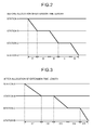
- FIG. 2 is a diagram illustrating an example of the basic operation plan displayed on the display device 52, and denoting the run time length between the station A and the station B as t1, the stoppage time length at the station B as t2, the run time length between the station B and the station C as t3, the stoppage time length at the station C as t4, and the run time length between the station C and the station D as t5.
- the basic operation plan created based on the highest speed may be referred to as a highest-speed basic operation plan, and the basic operation plan created based on the run time lengths designated through the input device 51 may be referred to as a designated basic operation plan.
- the operation plan creating function 15 not only creates the basic operation plan, but also calculates the total extension time length.
- the total extension time length is the time obtained by subtracting the sum of the basic run time lengths of the inter-stop sections and the designated stoppage time lengths at the stations from the total run time length set by the operation plan condition setting function 12. The calculated total extension time length is then provided to the run-curve calculating function 14.
- the operation plan creating function 15 determines inter-stop extension time lengths for the inter-stop sections in such a manner that the total energy consumption consumed across the entire operation section is minimized.
- the operation plan creating function 15 creates the optimal operation plan in which the inter-stop sections are allocated with the inter-stop extension time lengths in such a manner that the total energy consumption is minimized.
- the created optimal operation plan is sent to the display device 52 through the interface 16 and is displayed on the display device 52.
- FIG. 3 is a diagram illustrating an example of the optimal operation plan displayed on the display device 52 and created after the inter-stop extension time lengths are allocated so as to minimize the total energy consumption.
- FIG. 3 denotes the run time length between the station A and the station B as t11, the stoppage time length at the station B as t12, the run time length between the station B and the station C as t13, the stoppage time length at the station C as t14, and the run time length between the station C and the station D as t15.
- the inter-stop extension time lengths are allocated in such a manner that the total energy consumption is minimized, but the embodiment is not limited thereto.
- a predetermined number of combinations of inter-stop extension time lengths may be selected, as candidates, from combinations capable of achieving the minimum total energy consumption, and a combination achieving comfort in view of accelerations and decelerations may be selected from the selected candidates, for example.
- the total extension time length is ten seconds, and this total extension time length of ten seconds is allocated among the three inter-stop sections from the station A to the station D. It is assumed that, in the example explained below, the upper boundary of the inter-stop extension time length that can be allocated to one inter-stop section is five seconds.
- the run-curve calculating function 14 assumes that each one of the inter-stop extension time length is extended in the increment of every given unit time, e.g., one second, within the range equal to or lower than the upper boundary of the time that can be allocated to one inter-stop section, but not exceeding the total extension time length.
- the run-curve calculating function 14 then calculates the run-curve and the inter-stop energy consumption for each of the assumed inter-stop extension time lengths.
- the run-curve calculating function 14 assumes the following six patterns, as an inter-stop extension time length to be allocated to each of the inter-stop sections: (1) no time allocation (zero-second allocation); (2) one-second allocation; (3) two-second allocation; (4) three-second allocation; (5) four-second allocation; and (6) five-second allocation.
- the run-curve calculating function 14 then calculates, for each of the inter-stop sections, six different corrected run time lengths by adding the respective six different inter-stop extension time lengths to the basic run time length.
- the run-curve calculating function 14 acquires the run-curves assuming that train runs based on the respective corrected run time lengths, and the run-curve calculating function 14 calculates the respective inter-stop energy consumptions.
- the run-curve under the above-described assumption (1) is not calculated again, because it has been already calculated as the basic run-curve.
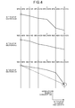
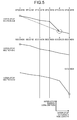
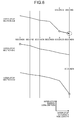
- the line graphs illustrated in FIGS. 4 to 6 respectively represent a relationship between the different inter-stop extension time lengths and the inter-stop energy consumptions.
- the operation plan creating function 15 selects the combination of the inter-stop section and an inter-stop extension time length that achieve the highest reduction ratio in the inter-stop energy consumption, based on the relationship between the inter-stop extension time lengths and the inter-stop energy consumptions calculated by the run-curve calculating function 14.
- a reduction ratio in the inter-stop energy consumption herein is the quotient resultant of dividing the amount of reduced inter-stop energy consumption by the inter-stop extension time length, and can be represented as the inclination of the line connecting the nodes in the line graph illustrated in each of FIGS. 4 to 6 .
- the operation plan creating function 15 allocates five seconds of ten seconds of the total extension time length to the inter-stop section C-D. This allocation causes the allocable total extension time length to be reduced by five seconds from ten seconds to five seconds. Consequently, since the inter-stop extension time length for the inter-stop section C-D reaches the upper boundary, the remaining five seconds of the total extension time length is allocated to one or both of the inter-stop section A-B and the inter-stop section B-C.
- the operation plan creating function 15 allocates four seconds out of the remaining five seconds of the total extension time length to the inter-stop section A-B. This allocation causes the allocable total extension time length to be reduced by four seconds from five seconds to one second.
- the operation plan creating function 15 allocates the remaining one second of the total extension time length to the inter-stop section A-B.
- the creator of the operation plan may set (input) a time allowance as an operation plan condition so that a delay of the train operation in an inter-stop section is not propagated to the next inter-stop section.
- This input of the time allowance is received, for example, after the basic operation plan as illustrated in FIG. 2 is displayed on the display device 52.
- the operation plan creating function 15 sets, as the total extension time length, a time length obtained by subtracting the sum of the stoppage time lengths, the basic run time lengths, and the time allowance from the total run time length.
- the operation plan creating function 15 then allocates the set total extension time length to the inter-stop sections so as to minimize the total energy consumption.
- the operation plan creating function 15 allocates the total extension time length, which is obtained by subtracting the sum of the stoppage time lengths and the basic run time lengths from the total run time length, to the inter-stop sections.
- the operation plan creation unit 11 executes a process of receiving inputs of operation plan conditions (e.g., a car type, an operation type, an operation section, and total run time length) through the input device 51 at Step S1, and the process is shifted to Step S2.
- operation plan conditions e.g., a car type, an operation type, an operation section, and total run time length
- the operation plan condition setting function 12 executes a process of determining whether the input of the operation plan conditions through the input device 51 has been completed. If the operation plan condition setting function 12 determines that the input of the operation plan conditions has not been completed at Step S2, the operation plan condition setting function 12 shifts the process back to Step S1. If the operation plan condition setting function 12 determines that the input of the operation plan conditions has been completed at Step S2, the operation plan condition setting function 12 shifts the process to Step S3.
- the run-curve condition setting function 13 and the run-curve calculating function 14 retrieve the database 53 based on the input operation plan conditions, extract the data required in creating run-curves (such as the route information, the operation information, and the car information) in addition to the entered operation plan conditions, and set the run-curve conditions at Step S3.
- the run-curve condition setting function 13 retrieves the database 53 and identifies the stop stations based on the input operation section and the operation type information; and the run-curve calculating function 14 retrieves the database 53 based on the input car type and operation section information, and extracts the matching car information and route information.
- Step S4 based on the run time lengths (designated run time lengths) entered through the input device 51, the car information and the route information extracted at Step S3, and the stop station information identified by the run-curve condition setting function 13, the run-curve calculating function 14 calculates the run-curve (basic run-curve) and the energy consumption assuming that the train runs for the entered run time length in one of the inter-stop sections in the operation section. Meanwhile, if the "run at highest speed" is designated through the input device 51, the run-curve calculating function 14 calculates the run-curve and the energy consumption assuming that train runs the inter-stop section at the highest speed. The process is then shifted to Step S5, and the process at Step 4 is repeated until the basic run-curve is calculated for each inter-stop section set by the run-curve condition setting function 13.
- Step S5 If it is determined that the basic run-curve has been calculated for each inter-stop section at Step S5, the process is shifted to Step S6, and the run-curve calculating function 14 creates the basic operation plan based on the basic run-curves for all the calculated inter-stop sections.
- the basic operation plan created at this time becomes a highest-speed basic operation plan when the highest speed is used as a condition, and becomes a designated basic operation plan when the run time length designated through the input device 51 is used as the condition.
- the basic operation plan created in this manner is represented in the format illustrated in FIG. 2 as mentioned above, and the operation plan creation unit 11 displays this basic operation plan on the display device 52. The process is then shifted to Step S7.
- the operation plan creating function 15 waits for an input including an item that relates to the presence of the setting of the time allowance for preventing a delay in the train operation in any one of the inter-stop sections from propagating to the next inter-stop section in the operation section.
- the operation plan creating function 15 executes a process of determining whether the time allowance is entered through the input device 51. At Step S8, if the operation plan creating function 15 determines that the time allowance has not been entered, the process is shifted back to Step S7. If the operation plan creating function 15 determines that the time allowance or "no setting of time allowance" has been entered at Step S8, the process is shifted to Step S9.
- the operation plan creating function 15 executes a process of calculating the total extension time length.
- the total extension time length herein means that the time obtained by subtracting the sum of the train stoppage time lengths at all of the respective stations, the basic run time lengths, and the time allowance from the total run time length. Meanwhile, if the time allowance is unset, that is, if "no setting of time allowance" is entered, the operation plan creating function 15 calculates the total extension time length by subtracting the sum of the basic run time lengths and the stoppage time lengths from the total run time length. The process is then shifted to Step S10.
- the run-curve calculating function 14 obtains a plurality of corrected run time lengths by adding a plurality of inter-stop extension time lengths to each of the basic run time lengths within the range not exceeding the total extension time length, and calculates a plurality of run-curves and a plurality of inter-stop energy consumptions to be consumed in the inter-stop section based on the corrected run time lengths. Specifically, to begin with, the run-curve calculating function 14 calculates a plurality of inter-stop extension time lengths (zero seconds to five seconds) that can be allocated to each of the inter-stop sections, within the range equal to or below the upper boundary (five seconds in the example illustrated in FIGS.
- the run-curve calculating function 14 then calculates a plurality of run-curves and a plurality of inter-stop energy consumptions corresponding to the calculated inter-stop extension time lengths. The process is then shifted to Step S11.
- the operation plan creating function 15 executes a process of allocating the inter-stop extension time lengths to the respective inter-stop sections in such a manner that the total energy consumption consumed in the entire operation section is minimized. Specifically, the operation plan creating function 15 executes a process of allocating the total extension time length to the inter-stop sections according to the steps explained above with reference to FIGS. 4 to 6 , based on the inter-stop energy consumptions corresponding to the inter-stop extension time lengths acquired by the run-curve calculating function 14 through the process at Step S10. The process is then shifted to Step S12.
- the operation plan creating function 15 creates the optimal operation plan as illustrated in FIG. 3 , for example, based on the inter-stop extension time lengths allocated to the inter-stop sections in a manner minimizing the total energy consumption through the process at Step S11.
- the operation plan creation unit 11 displays the created optimal operation plan on the display device 52. The process is then ended.
- the run-curve calculating function 14 is configured: to acquire a plurality of corrected run time lengths obtained by adding the inter-stop extension time lengths each with a different length to the basic run time length corresponding to each of the inter-stop sections; and to calculate the inter-stop energy consumptions corresponding to the corrected run time lengths.
- the operation plan creating function 15 is configured to determine the inter-stop extension time lengths to be allocated to the inter-stop sections based on a relationship between the inter-stop extension time lengths having different lengths and the inter-stop energy consumptions which are calculated by the run-curve calculating function 14, so that the total energy consumption consumed across the entire operation section is minimized when the total extension time length is allocated across the inter-stop sections. With this configuration, it is possible to generate the optimal operation plan achieving high energy consumption efficiency.
- the second embodiment is different from the first embodiment in that a relationship between the allocation reference times (which correspond to a plurality of inter-stop extension time lengths having different lengths in the first embodiment) and the inter-stop energy consumptions is stored in a database 63 in advance.
- the operation plan creation device 200 includes a creation device main unit 20 having an operation plan creation unit 21, in the same manner as the operation plan creation device 100 according to the first embodiment.
- the operation plan creation unit 21 includes, as the functional modules, an operation plan condition setting function 22, a run-curve condition setting function 23, a run-curve calculating function 24, and an operation plan creating function 25.
- the operation plan creation unit 21 is connected to the input device 51, the display device 52, and the database 63 through an interface 26.
- the database 63 is an example of the "storage unit".
- the operation plan creating function 25 calculates the total extension time length by subtracting the sum of the basic run time lengths of the respective inter-stop sections and the stoppage time lengths at the respective stations from the total run time length across the operation section. The operation plan creating function 25 then allocates the calculated total extension time length to the inter-stop sections in such a manner that the total energy consumption consumed across the entire operation section is minimized. Meanwhile, if the time allowance is set as explained in the first embodiment, the sum to be subtracted from the total run time length is the sum of the basic run time lengths of the respective inter-stop sections, the stoppage time lengths at the respective stations, and the time allowance corresponding to the inter-stop sections.
- the basic run time lengths of the inter-stop sections which are used in calculating the total extension time length, are calculated based on the run-curves calculated by the run-curve calculating function 24 based on the run-curves being calculated under the conditions set by the operation plan condition setting function 22, the run-curve condition setting function 23, and the like.
- the database 63 stores therein, in advance, the relationship between the allocation reference time lengths having different lengths, and the inter-stop energy consumptions consumed in the respective inter-stop sections when the respective allocation reference time lengths are allocated.
- the operation plan creating function 25 sequentially repeats, within the range in which the sum of the allocated allocation reference time lengths is equal to or less than the total extension time length, a process of: selecting the combination of an inter-stop section and the allocation reference time length for maximizing the reduction degree of the inter-stop energy consumption based on the mapping relations read out from the database 63; and allocating the selected allocation reference time length to the selected inter-stop section.
- the operation plan creation device has a hardware configuration that uses a general computer, and the control program executed by the operation plan creation device is stored in a computer-readable recording medium (e.g., a compact disc read-only memory (CD-ROM), a flexible disk (FD), a compact disc recordable (CD-R), or a digital versatile disc (DVD)), as a file in an installable or executable format to be provided.
- a computer-readable recording medium e.g., a compact disc read-only memory (CD-ROM), a flexible disk (FD), a compact disc recordable (CD-R), or a digital versatile disc (DVD)
- the control program may be stored in a computer connected to a network such as the Internet, and provided or distributed over the network.
- the control program may also be provided incorporated in a ROM or the like in advance.
Landscapes
- Engineering & Computer Science (AREA)
- Power Engineering (AREA)
- Transportation (AREA)
- Mechanical Engineering (AREA)
- Train Traffic Observation, Control, And Security (AREA)
Abstract
Description
- Embodiments of the present invention relate to an operation plan creation device.
- Recently, in order to reduce burdens imposed on the environment and to make effective use of resources, there has been a demand for promoting further energy savings in trains which are energy-efficient transportation. Although weight reductions in train cars and improvements in motors and inverters can achieve great deal of energy saving, such improvements require updates in facilities, and therefore will increase costs. Therefore, techniques, which achieve energy savings without accruing as much cost by changing operation plans such as an inter-stop train operation and a train diagram, have been considered.
-
- Patent Literature 1:
Japanese Laid-open Patent Publication No. 7-165080 - Patent Literature 2:
Japanese Laid-open Patent Publication No. 2004-155314 - In the above-mentioned techniques, it is desirable to generate an operation plan that can achieve reductions in energy consumptions across the entire service section, for example.
- An operation plan creation device according to an embodiment comprises a storage unit and an operation plan creation unit. The storage unit is configured to store therein route information, operation information, and car information. The operation plan creation unit comprises an operation plan condition setting module, a run-curve condition setting module, a run-curve creation module, and an operation plan creation module. The operation plan condition setting module is configured to receive car type information, operation type information, operation section information, and a total run time length from a starting station to a destination station, through an input device. The run-curve condition setting module is configured: to retrieve the storage unit based on the operation type information and the operation section information received by the operation plan condition setting module; to identify stop stations to set inter-stop sections for which run-curves are to be created; and to set run time lengths between the stop stations based on an input from the input device. The run-curve creation module is configured: to retrieve the storage unit to extract the route information and the car information based on the car type information and the operation section information received by the operation plan condition setting module; to acquire a first run-curve and a first energy consumption in each of the inter-stop sections based on the extracted route information and car information and the inter-stop sections set by the run-curve condition setting module; to correct, when a total extension time length is set, the run time lengths set by the run-curve condition setting module based on the total extension time length; and to acquire a second run-curve based on the corrected run time lengths. The operation plan creation module is configured: to acquire the total extension time length based on the total run time length, the run time lengths in the inter-stop sections, and stoppage time lengths included in the operation information stored in the storage unit; to notify the run-curve creation module of the acquired total extension time length; and to create an operation plan based on the second run-curve.
-
-
FIG. 1 is a diagram illustrating an exemplary configuration of an operation plan creation device according to a first embodiment. -
FIG. 2 is a diagram illustrating an example of an operation plan before an operation plan creating function of the operation plan creation device allocates an extension time length, according to the first embodiment. -
FIG. 3 is a diagram illustrating an example of the operation plan after the operation plan creating function of the operation plan creation device allocates the extension time length, according to the first embodiment. -
FIG. 4 is a diagram for explaining steps for allocating the extension time length by the operation plan creating function of the operation plan creation device according to the first embodiment. -
FIG. 5 is a diagram for explaining steps for allocating the extension time length by the operation plan creating function of the operation plan creation device according to the first embodiment. -
FIG. 6 is a diagram for explaining steps for allocating the extension time length by the operation plan creating function of the operation plan creation device according to the first embodiment. -
FIG. 7 is a flowchart illustrating an example of a process performed by the operation plan creation device according to the first embodiment. -
FIG. 8 is a diagram illustrating an exemplary configuration of an operation plan creation device according to a second embodiment. - Embodiments will now be explained with reference to some drawings.
- To begin with, an exemplary configuration of an operation
plan creation device 100 according to a first embodiment will now be explained with reference toFIGS. 1 to 6 . - As illustrated in
FIG. 1 , the operationplan creation device 100 includes a creation device main unit 10, aninput device 51, adisplay device 52, and adatabase 53. Thedatabase 53 is an example of a "storage unit". The creation device main unit 10 mainly includes an operation plan creation unit 11 and aninterface 16. Theinput device 51, thedisplay device 52, and thedatabase 53 are connected to the creation device main unit 10 through theinterface 16. The operation plan creation unit 11 executes various functions, such as an operation plan condition setting function 12, a run-curvecondition setting function 13, a run-curve calculating function 14, and an operation plan creating function (extension time allocating function) 15. - In the exemplary configuration illustrated in
FIG. 1 , thedatabase 53 is externally connected to the creation device main unit 10. However, thedatabase 53 may be internally installed in the creation device main unit 10. In a configuration in which thedatabase 53 is installed internally, thedatabase 53 is connected to the operation plan creation unit 11 through an internal bus instead of through theinterface 16 for connecting to external devices. - The
database 53 stores therein various types of data required in calculating a run-curve. The data mainly includes route information, operation information, and car information. These pieces of information include the following items. - (1) Route information: for example, the locations of stations, gradients, curves, boundaries between block sections, speed limitations, and overhead wire voltages;
- (2) Operation information: for example, operation types, stop stations, and stoppage time lengths at respective stations; and
- (3) Car information: for example, the weight for each car type, the number of cars in a train, acceleration and deceleration characteristics, and highest speeds.
- The operation plan condition setting function 12 executes a process of setting operation plan conditions based on information that is entered through the
input device 51, such as a mouse or a keyboard, or selected from and entered through a selection menu displayed on thedisplay device 52, and is received through theinterface 16. Examples of the operation plan condition include a car type, an operation type, an operation section, and a total run time length. The operation section represents a section from a starting station to a destination station for which a train diagram is created. The total run time length represents the run time for which the train travels from the starting station to the destination station. - The operation plan condition may also include, for example, the voltage of the overhead wire in the operation section, a margin to the speed limitation set in the operation section, and the like. The respective standard values are set to the voltage of the overhead wire, the margin, and the like unless corresponding inputs are entered through the
input device 51. - The run-curve
condition setting function 13 executes a process of setting the conditions to create a run-curve for inter-stop sections within an operation section (i.e., run-curve conditions). Specifically, the run-curvecondition setting function 13 retrieves thedatabase 53 based on the operation section and the operation type set by the operation plan condition setting function 12, and identifies the stop stations corresponding to the operation type among the stations included in the operation section. The run-curvecondition setting function 13 then sets, based on the identified stop stations, inter-stop sections for which run-curves are to be created. In other words, the run-curvecondition setting function 13 identifies, as a target for which the run-curve is to be created, a section between two stop stations that is adjacent when the stop stations are arranged in the temporal order. - The run-curve
condition setting function 13 also sets, as a run-curve condition, run time lengths for which the train runs across each of the inter-stop sections included in the operation section as well as the inter-stop sections for which the run-curves are to be created. When "run at highest speed", instead of the run time lengths, is designated for the inter-stop sections in the operation section through theinput device 51, the run-curvecondition setting function 13 does not set any run time length as a run-curve condition. - The run-curve calculating function 14 retrieves the
database 53 based on the information of the car type and the operation section set by the operation plan condition setting function 12, and reads out the corresponding car information and route information. Based on the read car information, the route information, the information of the target inter-stop sections for which respective run-curves are to be created, and the information of the run time lengths set by the run-curvecondition setting function 13, the run-curve calculating function 14 calculates run-curves (first run-curves) and inter-stop energy consumptions (first energy consumptions) for each inter-stop section. When no run time length is set, the run-curve calculating function 14 calculates a run-curve, an inter-stop energy consumption, and the shortest run time length assuming that the train runs the inter-stop section at the highest speed. The designated run time length or the shortest run time length is referred to as a basic run time length, and the calculated run-curve is referred to as a basic run-curve. - When the run-curve calculating function 14 receives a total extension time length that is determined by the operation
plan creating function 15, the run-curve calculating function 14 sets a plurality of inter-stop extension time lengths within the range not exceeding the total extension time length, and calculates run-curves (second run-curves) and respective inter-stop energy consumptions (second energy consumptions) based on corrected run time lengths that are the additions of the respective inter-stop extension time lengths and each of the basic run time lengths of the respective inter-stop sections. - After the run-curve calculating function 14 calculates the run-curves that are based on the respective basic run time lengths, which are the basic run-curves, the operation
plan creating function 15 creates an operation plan (basic operation plan) corresponding to the basic run-curves. The basic operation plan is an operation plan created under the assumption that, when the run-curvecondition setting function 13 designates "run at highest speed", the train runs each inter-stop section at the highest speed and stops for designated stoppage time lengths at the respective stations. By contrast, when the run-curvecondition setting function 13 sets the run time lengths that are entered through theinput device 51, the basic operation plan is an operation plan under the assumption that the train runs the inter-stop sections for each entered time length and stops for the designated stoppage time lengths at the respective stations. - When the basic operation plan is created, the operation plan creation unit 11 sends the basic operation plan to the
display device 52 through theinterface 16, and the basic operation plan is displayed on thedisplay device 52.FIG. 2 is a diagram illustrating an example of the basic operation plan displayed on thedisplay device 52, and denoting the run time length between the station A and the station B as t1, the stoppage time length at the station B as t2, the run time length between the station B and the station C as t3, the stoppage time length at the station C as t4, and the run time length between the station C and the station D as t5. - Note that the basic operation plan created based on the highest speed may be referred to as a highest-speed basic operation plan, and the basic operation plan created based on the run time lengths designated through the
input device 51 may be referred to as a designated basic operation plan. - The operation
plan creating function 15 not only creates the basic operation plan, but also calculates the total extension time length. The total extension time length is the time obtained by subtracting the sum of the basic run time lengths of the inter-stop sections and the designated stoppage time lengths at the stations from the total run time length set by the operation plan condition setting function 12. The calculated total extension time length is then provided to the run-curve calculating function 14. - When the run-curve calculating function 14 calculates the inter-stop energy consumptions corresponding to the corrected run time lengths, the operation
plan creating function 15 determines inter-stop extension time lengths for the inter-stop sections in such a manner that the total energy consumption consumed across the entire operation section is minimized. The operationplan creating function 15 creates the optimal operation plan in which the inter-stop sections are allocated with the inter-stop extension time lengths in such a manner that the total energy consumption is minimized. The created optimal operation plan is sent to thedisplay device 52 through theinterface 16 and is displayed on thedisplay device 52. The process of allocating the inter-stop extension time lengths, and a relationship between an inter-stop energy consumption and an allocated inter-stop extension time length will be described later in detail. -
FIG. 3 is a diagram illustrating an example of the optimal operation plan displayed on thedisplay device 52 and created after the inter-stop extension time lengths are allocated so as to minimize the total energy consumption.FIG. 3 denotes the run time length between the station A and the station B as t11, the stoppage time length at the station B as t12, the run time length between the station B and the station C as t13, the stoppage time length at the station C as t14, and the run time length between the station C and the station D as t15. - In the description cited above, the inter-stop extension time lengths are allocated in such a manner that the total energy consumption is minimized, but the embodiment is not limited thereto. Alternatively, a predetermined number of combinations of inter-stop extension time lengths may be selected, as candidates, from combinations capable of achieving the minimum total energy consumption, and a combination achieving comfort in view of accelerations and decelerations may be selected from the selected candidates, for example.
- The process of allocating the inter-stop extension time lengths will now be explained in detail with reference to
FIGS. 4 to 6 . - Explained now is an example in which the total extension time length is ten seconds, and this total extension time length of ten seconds is allocated among the three inter-stop sections from the station A to the station D. It is assumed that, in the example explained below, the upper boundary of the inter-stop extension time length that can be allocated to one inter-stop section is five seconds.
- To begin with, after receiving a total extension time length calculated by the operation
plan creating function 15, the run-curve calculating function 14 assumes that each one of the inter-stop extension time length is extended in the increment of every given unit time, e.g., one second, within the range equal to or lower than the upper boundary of the time that can be allocated to one inter-stop section, but not exceeding the total extension time length. The run-curve calculating function 14 then calculates the run-curve and the inter-stop energy consumption for each of the assumed inter-stop extension time lengths. In the example mentioned above, the run-curve calculating function 14 assumes the following six patterns, as an inter-stop extension time length to be allocated to each of the inter-stop sections: (1) no time allocation (zero-second allocation); (2) one-second allocation; (3) two-second allocation; (4) three-second allocation; (5) four-second allocation; and (6) five-second allocation. The run-curve calculating function 14 then calculates, for each of the inter-stop sections, six different corrected run time lengths by adding the respective six different inter-stop extension time lengths to the basic run time length. The run-curve calculating function 14 then acquires the run-curves assuming that train runs based on the respective corrected run time lengths, and the run-curve calculating function 14 calculates the respective inter-stop energy consumptions. The run-curve under the above-described assumption (1) is not calculated again, because it has been already calculated as the basic run-curve. The line graphs illustrated inFIGS. 4 to 6 respectively represent a relationship between the different inter-stop extension time lengths and the inter-stop energy consumptions. - The operation
plan creating function 15 then selects the combination of the inter-stop section and an inter-stop extension time length that achieve the highest reduction ratio in the inter-stop energy consumption, based on the relationship between the inter-stop extension time lengths and the inter-stop energy consumptions calculated by the run-curve calculating function 14. A reduction ratio in the inter-stop energy consumption herein is the quotient resultant of dividing the amount of reduced inter-stop energy consumption by the inter-stop extension time length, and can be represented as the inclination of the line connecting the nodes in the line graph illustrated in each ofFIGS. 4 to 6 . - As illustrated in
FIG. 4 , in the initial state in which no inter-stop extension time length allocated to any of these inter-stop sections, a segment of the line graph presenting the inter-stop section C-D connecting the nodes at zero seconds and five seconds (see the dotted line with an arrow) is inclined by the greatest degree. Therefore, to begin with, the operationplan creating function 15 allocates five seconds of ten seconds of the total extension time length to the inter-stop section C-D. This allocation causes the allocable total extension time length to be reduced by five seconds from ten seconds to five seconds. Consequently, since the inter-stop extension time length for the inter-stop section C-D reaches the upper boundary, the remaining five seconds of the total extension time length is allocated to one or both of the inter-stop section A-B and the inter-stop section B-C. - As illustrated in
FIG. 5 , after the inter-stop time of five seconds is allocated to the inter-stop section C-D, a segment of the line graph presenting the inter-stop section A-B connecting the nodes at zero seconds and four seconds (see the dotted line with an arrow) is inclined by the greatest degree. Therefore, the operationplan creating function 15 allocates four seconds out of the remaining five seconds of the total extension time length to the inter-stop section A-B. This allocation causes the allocable total extension time length to be reduced by four seconds from five seconds to one second. - As illustrated in
FIG. 6 , after the inter-stop extension time length of four seconds is allocated to the inter-stop section A-B, there is only remaining one second of the total extension time length. Therefore, in this case, only one second at the maximum can be allocated to the inter-stop section B-C. Comparing the segment of the line graph presenting the inter-stop section A-B connecting the node at zero seconds (i.e., at four seconds in a case where the inter-stop extension time length has not been allocated) and the node at one second (i.e., at five seconds in a case where the inter-stop extension time length has not been allocated) with the segment of the line graph presenting the inter-stop section B-C connecting the node at zero seconds and the node at one second, the former segment is inclined by the greatest degree (see the dotted line with an arrow). Therefore, the operationplan creating function 15 allocates the remaining one second of the total extension time length to the inter-stop section A-B. As a result, to the inter-stop section A-B, five seconds of the inter-stop extension time length is allocated in total, including the inter-stop extension time length of four seconds having been previously allocated (seeFIG. 5 ). This allocation causes the allocable total extension time length reaches zero seconds, and therefore the process is ended. - By allocating the extension time lengths to the inter-stop sections according to the above-described process, the total energy consumption consumed across the entire operation section is minimized.
- Meanwhile, the creator of the operation plan may set (input) a time allowance as an operation plan condition so that a delay of the train operation in an inter-stop section is not propagated to the next inter-stop section. This input of the time allowance is received, for example, after the basic operation plan as illustrated in
FIG. 2 is displayed on thedisplay device 52. When the time allowance is entered, the operationplan creating function 15 sets, as the total extension time length, a time length obtained by subtracting the sum of the stoppage time lengths, the basic run time lengths, and the time allowance from the total run time length. The operationplan creating function 15 then allocates the set total extension time length to the inter-stop sections so as to minimize the total energy consumption. Meanwhile, when an input indicating that "no time allowance set" is entered, the operationplan creating function 15 allocates the total extension time length, which is obtained by subtracting the sum of the stoppage time lengths and the basic run time lengths from the total run time length, to the inter-stop sections. - An example of the process of creating and displaying the operation plan, performed by the operation
plan creation device 100 according to the first embodiment will now be explained with reference toFIG. 7 . - In this process flow as illustrated in
FIG. 7 , the operation plan creation unit 11 executes a process of receiving inputs of operation plan conditions (e.g., a car type, an operation type, an operation section, and total run time length) through theinput device 51 at Step S1, and the process is shifted to Step S2. - At Step S2, the operation plan condition setting function 12 executes a process of determining whether the input of the operation plan conditions through the
input device 51 has been completed. If the operation plan condition setting function 12 determines that the input of the operation plan conditions has not been completed at Step S2, the operation plan condition setting function 12 shifts the process back to Step S1. If the operation plan condition setting function 12 determines that the input of the operation plan conditions has been completed at Step S2, the operation plan condition setting function 12 shifts the process to Step S3. - When the inputs of the operation plan conditions are completed, the run-curve
condition setting function 13 and the run-curve calculating function 14 retrieve thedatabase 53 based on the input operation plan conditions, extract the data required in creating run-curves (such as the route information, the operation information, and the car information) in addition to the entered operation plan conditions, and set the run-curve conditions at Step S3. In other words, the run-curvecondition setting function 13 retrieves thedatabase 53 and identifies the stop stations based on the input operation section and the operation type information; and the run-curve calculating function 14 retrieves thedatabase 53 based on the input car type and operation section information, and extracts the matching car information and route information. When this process is completed, the process is shifted to Step S4. - At Step S4, based on the run time lengths (designated run time lengths) entered through the
input device 51, the car information and the route information extracted at Step S3, and the stop station information identified by the run-curvecondition setting function 13, the run-curve calculating function 14 calculates the run-curve (basic run-curve) and the energy consumption assuming that the train runs for the entered run time length in one of the inter-stop sections in the operation section. Meanwhile, if the "run at highest speed" is designated through theinput device 51, the run-curve calculating function 14 calculates the run-curve and the energy consumption assuming that train runs the inter-stop section at the highest speed. The process is then shifted to Step S5, and the process atStep 4 is repeated until the basic run-curve is calculated for each inter-stop section set by the run-curvecondition setting function 13. - If it is determined that the basic run-curve has been calculated for each inter-stop section at Step S5, the process is shifted to Step S6, and the run-curve calculating function 14 creates the basic operation plan based on the basic run-curves for all the calculated inter-stop sections. The basic operation plan created at this time becomes a highest-speed basic operation plan when the highest speed is used as a condition, and becomes a designated basic operation plan when the run time length designated through the
input device 51 is used as the condition. The basic operation plan created in this manner is represented in the format illustrated inFIG. 2 as mentioned above, and the operation plan creation unit 11 displays this basic operation plan on thedisplay device 52. The process is then shifted to Step S7. - At Step S7, the operation
plan creating function 15 waits for an input including an item that relates to the presence of the setting of the time allowance for preventing a delay in the train operation in any one of the inter-stop sections from propagating to the next inter-stop section in the operation section. - At Step S8, the operation
plan creating function 15 executes a process of determining whether the time allowance is entered through theinput device 51. At Step S8, if the operationplan creating function 15 determines that the time allowance has not been entered, the process is shifted back to Step S7. If the operationplan creating function 15 determines that the time allowance or "no setting of time allowance" has been entered at Step S8, the process is shifted to Step S9. - At Step S9, the operation
plan creating function 15 executes a process of calculating the total extension time length. The total extension time length herein means that the time obtained by subtracting the sum of the train stoppage time lengths at all of the respective stations, the basic run time lengths, and the time allowance from the total run time length. Meanwhile, if the time allowance is unset, that is, if "no setting of time allowance" is entered, the operationplan creating function 15 calculates the total extension time length by subtracting the sum of the basic run time lengths and the stoppage time lengths from the total run time length. The process is then shifted to Step S10. - At Step S10, the run-curve calculating function 14 obtains a plurality of corrected run time lengths by adding a plurality of inter-stop extension time lengths to each of the basic run time lengths within the range not exceeding the total extension time length, and calculates a plurality of run-curves and a plurality of inter-stop energy consumptions to be consumed in the inter-stop section based on the corrected run time lengths. Specifically, to begin with, the run-curve calculating function 14 calculates a plurality of inter-stop extension time lengths (zero seconds to five seconds) that can be allocated to each of the inter-stop sections, within the range equal to or below the upper boundary (five seconds in the example illustrated in
FIGS. 4 to 6 ) and the total extension time length (ten seconds in the example illustrated inFIGS. 4 to 6 ). The run-curve calculating function 14 then calculates a plurality of run-curves and a plurality of inter-stop energy consumptions corresponding to the calculated inter-stop extension time lengths. The process is then shifted to Step S11. - At Step S11, the operation
plan creating function 15 executes a process of allocating the inter-stop extension time lengths to the respective inter-stop sections in such a manner that the total energy consumption consumed in the entire operation section is minimized. Specifically, the operationplan creating function 15 executes a process of allocating the total extension time length to the inter-stop sections according to the steps explained above with reference toFIGS. 4 to 6 , based on the inter-stop energy consumptions corresponding to the inter-stop extension time lengths acquired by the run-curve calculating function 14 through the process at Step S10. The process is then shifted to Step S12. - At Step S12, the operation
plan creating function 15 creates the optimal operation plan as illustrated inFIG. 3 , for example, based on the inter-stop extension time lengths allocated to the inter-stop sections in a manner minimizing the total energy consumption through the process at Step S11. The operation plan creation unit 11 then displays the created optimal operation plan on thedisplay device 52. The process is then ended. - As explained above, in the first embodiment, the run-curve calculating function 14 is configured: to acquire a plurality of corrected run time lengths obtained by adding the inter-stop extension time lengths each with a different length to the basic run time length corresponding to each of the inter-stop sections; and to calculate the inter-stop energy consumptions corresponding to the corrected run time lengths. In addition, the operation
plan creating function 15 is configured to determine the inter-stop extension time lengths to be allocated to the inter-stop sections based on a relationship between the inter-stop extension time lengths having different lengths and the inter-stop energy consumptions which are calculated by the run-curve calculating function 14, so that the total energy consumption consumed across the entire operation section is minimized when the total extension time length is allocated across the inter-stop sections. With this configuration, it is possible to generate the optimal operation plan achieving high energy consumption efficiency. - An operation
plan creation device 200 according to a second embodiment will now be explained with reference toFIG. 8 . The second embodiment is different from the first embodiment in that a relationship between the allocation reference times (which correspond to a plurality of inter-stop extension time lengths having different lengths in the first embodiment) and the inter-stop energy consumptions is stored in adatabase 63 in advance. - As illustrated in
FIG. 8 , the operationplan creation device 200 according to the second embodiment includes a creation device main unit 20 having an operation plan creation unit 21, in the same manner as the operationplan creation device 100 according to the first embodiment. The operation plan creation unit 21 includes, as the functional modules, an operation plan condition setting function 22, a run-curve condition setting function 23, a run-curve calculating function 24, and an operationplan creating function 25. The operation plan creation unit 21 is connected to theinput device 51, thedisplay device 52, and thedatabase 63 through aninterface 26. Thedatabase 63 is an example of the "storage unit". - In the second embodiment, the operation
plan creating function 25 calculates the total extension time length by subtracting the sum of the basic run time lengths of the respective inter-stop sections and the stoppage time lengths at the respective stations from the total run time length across the operation section. The operationplan creating function 25 then allocates the calculated total extension time length to the inter-stop sections in such a manner that the total energy consumption consumed across the entire operation section is minimized. Meanwhile, if the time allowance is set as explained in the first embodiment, the sum to be subtracted from the total run time length is the sum of the basic run time lengths of the respective inter-stop sections, the stoppage time lengths at the respective stations, and the time allowance corresponding to the inter-stop sections. The basic run time lengths of the inter-stop sections, which are used in calculating the total extension time length, are calculated based on the run-curves calculated by the run-curve calculating function 24 based on the run-curves being calculated under the conditions set by the operation plan condition setting function 22, the run-curve condition setting function 23, and the like. - In the second embodiment, as described above, the
database 63 stores therein, in advance, the relationship between the allocation reference time lengths having different lengths, and the inter-stop energy consumptions consumed in the respective inter-stop sections when the respective allocation reference time lengths are allocated. The operationplan creating function 25 sequentially repeats, within the range in which the sum of the allocated allocation reference time lengths is equal to or less than the total extension time length, a process of: selecting the combination of an inter-stop section and the allocation reference time length for maximizing the reduction degree of the inter-stop energy consumption based on the mapping relations read out from thedatabase 63; and allocating the selected allocation reference time length to the selected inter-stop section. With this configuration, also in the second embodiment, similarly to the first embodiment, it is possible to allocate the total extension time length to the inter-stop sections so as to minimize the total energy consumption consumed across the entire operation section. - As a result, it is possible to generate the optimal operation plan capable of reducing the total energy consumption consumed across the entire operation section.
- The operation plan creation device according to the above-described embodiments has a hardware configuration that uses a general computer, and the control program executed by the operation plan creation device is stored in a computer-readable recording medium (e.g., a compact disc read-only memory (CD-ROM), a flexible disk (FD), a compact disc recordable (CD-R), or a digital versatile disc (DVD)), as a file in an installable or executable format to be provided. The control program may be stored in a computer connected to a network such as the Internet, and provided or distributed over the network. The control program may also be provided incorporated in a ROM or the like in advance.
- While certain embodiments have been described, these embodiments have been presented by way of example only, and are not intended to limit the scope of the inventions. Indeed, the novel embodiments described herein may be embodied in a variety of other forms; furthermore, various omissions, substitutions and changes in the form of the embodiments described herein may be made without departing from the spirit of the inventions. The accompanying claims and their equivalents are intended to cover such forms or modifications as would fall within the scope and spirit of the inventions.
Claims (7)
- An operation plan creation device comprising:a storage unit configured to store therein route information, operation information, and car information; andan operation plan creation unit comprising:an operation plan condition setting module configured to receive car type information, operation type information, operation section information, and a total run time length from a starting station to a destination station, through an input device;a run-curve condition setting module configured:to retrieve the storage unit based on the operation type information and the operation section information received by the operation plan condition setting module;to identify stop stations to set inter-stop sections for which run-curves are to be created; andto set run time lengths between the stop stations based on an input from the input device;a run-curve creation module configured:to retrieve the storage unit to extract the route information and the car information based on the car type information and the operation section information received by the operation plan condition setting module;to acquire a first run-curve and a first energy consumption in each of the inter-stop sections based on the extracted route information and car information and the inter-stop sections set by the run-curve condition setting module;to correct, when a total extension time length is set, the run time lengths set by the run-curve condition setting module based on the total extension time length; andto acquire a second run-curve based on the corrected run time lengths; andan operation plan creation module configured:to acquire the total extension time length based on the total run time length, the run time lengths in the inter-stop sections, and stoppage time lengths included in the operation information stored in the storage unit;to notify the run-curve creation module of the acquired total extension time length; andto create an operation plan based on the second run-curve.
- The operation plan creation device according to claim 1, wherein the operation plan creation module is configured to acquire the total extension time length by subtracting the run time lengths in the inter-stop sections and the stoppage time lengths at the stop stations from the total run time length.
- The operation plan creation device according to claim 1, wherein the run-curve creation module is further configured to acquire a second energy consumption corresponding to the second run-curve based on the corrected run time lengths.
- The operation plan creation device according to claim 3, wherein
the run-curve creation module is configured:to acquire a plurality of inter-stop extension time lengths within a range of the total extension time length when the total extension time length is set, the inter-stop extension time lengths having a different time length and being allocated to each of the inter-stop sections set by the run-curve condition setting module; andto acquire a plurality of second run-curves and a plurality of second energy consumptions corresponding to the inter-stop extension time lengths; and
the operation plan creation module is configured:to select a least one of the second energy consumptions acquired by the run-curve creation module; andto create an operation plan based on the second run-curve corresponding to the selected second energy consumption. - The operation plan creation device according to claim 4, wherein the run-curve creation module is configured to acquire, when an upper boundary of an inter-stop extension time length is set, the plurality of inter-stop extension time lengths within a range of the total extension time length and the upper boundary.
- The operation plan creation device according to claim 4, wherein
the storage unit is further configured to store therein information representing a relationship between an inter-stop extension time length and the second energy consumption for each of the inter-stop sections, and
the run-curve creation module is configured to retrieve the storage unit based on the inter-stop extension time lengths that are acquired based on the total extension time length, and to acquire the second energy consumptions. - An operation plan creation device comprising:a storage unit that stores therein route information, operation information, and car information; andan operation plan creation unit, whereinthe operation plan creation unit is configured:to receive car type information, operation type information, operation section information, and a total run time length from a starting station to a destination station, through an input device;to retrieve the storage unit based on the received operation type information and the operation section information;to identify stop stations to set inter-stop sections for which run-curves are to be created;to set run time lengths between the stop stations based on an input from the input device;to retrieve the storage unit to extract the route information and the car information based on the received car type information and the operation section information;to acquire a first run-curve and a first energy consumption in each of the inter-stop sections based on the extracted route information and car information and the set inter-stop sections;to correct, when a total extension time length is set, the set run time lengths based on the total extension time length; andto acquire a second run-curve based on the corrected run time lengths;to acquire the total extension time length based on the total run time length, the run time lengths in the inter-stop sections, and stoppage time lengths included in the operation information stored in the storage unit;to create an operation plan based on the second run-curve.
Applications Claiming Priority (2)
| Application Number | Priority Date | Filing Date | Title |
|---|---|---|---|
| JP2013260564A JP6215032B2 (en) | 2013-12-17 | 2013-12-17 | Operation plan creation device |
| PCT/JP2014/082831 WO2015093388A1 (en) | 2013-12-17 | 2014-12-11 | Service plan creation device |
Publications (3)
| Publication Number | Publication Date |
|---|---|
| EP3090919A1 true EP3090919A1 (en) | 2016-11-09 |
| EP3090919A4 EP3090919A4 (en) | 2017-11-29 |
| EP3090919B1 EP3090919B1 (en) | 2019-12-04 |
Family
ID=53402735
Family Applications (1)
| Application Number | Title | Priority Date | Filing Date |
|---|---|---|---|
| EP14871246.6A Active EP3090919B1 (en) | 2013-12-17 | 2014-12-11 | Service plan creation device |
Country Status (4)
| Country | Link |
|---|---|
| EP (1) | EP3090919B1 (en) |
| JP (1) | JP6215032B2 (en) |
| PT (1) | PT3090919T (en) |
| WO (1) | WO2015093388A1 (en) |
Families Citing this family (4)
| Publication number | Priority date | Publication date | Assignee | Title |
|---|---|---|---|---|
| JP6552891B2 (en) * | 2015-06-30 | 2019-07-31 | 株式会社東芝 | On-board system and ground system |
| JP6707041B2 (en) * | 2017-02-23 | 2020-06-10 | 株式会社日立製作所 | Vehicle control system, method and vehicle |
| CN110160541B (en) | 2018-08-06 | 2022-02-22 | 腾讯大地通途(北京)科技有限公司 | Method and device for reconstructing motion trail, storage medium and electronic device |
| JP7445588B2 (en) * | 2020-12-21 | 2024-03-07 | 公益財団法人鉄道総合技術研究所 | Driving plan creation device and driving plan creation method |
Family Cites Families (8)
| Publication number | Priority date | Publication date | Assignee | Title |
|---|---|---|---|---|
| US4617627A (en) * | 1983-01-17 | 1986-10-14 | Hitachi, Ltd. | Method for automatic operation of a vehicle |
| JPH0629027B2 (en) * | 1984-10-08 | 1994-04-20 | 株式会社日立製作所 | Train operation control system |
| GB2263993B (en) * | 1992-02-06 | 1995-03-22 | Westinghouse Brake & Signal | Regulating a railway vehicle |
| JPH07165080A (en) | 1993-12-13 | 1995-06-27 | Hitachi Ltd | How to create a mobile operation plan |
| US6243694B1 (en) * | 1997-12-29 | 2001-06-05 | General Electric Company | System and method for generating a fuel-optimal reference velocity profile for a rail-based transportation handling controller |
| JP2001278052A (en) * | 2000-03-31 | 2001-10-10 | Kawasaki Heavy Ind Ltd | Method and system for supporting train schedule creation |
| JP3881302B2 (en) * | 2002-11-06 | 2007-02-14 | 財団法人鉄道総合技術研究所 | Driving curve creation device and running curve creation information |
| CN104192176B (en) * | 2014-05-19 | 2016-08-17 | 广州地铁集团有限公司 | A kind of method reducing metro traction energy consumption |
-
2013
- 2013-12-17 JP JP2013260564A patent/JP6215032B2/en active Active
-
2014
- 2014-12-11 WO PCT/JP2014/082831 patent/WO2015093388A1/en not_active Ceased
- 2014-12-11 PT PT148712466T patent/PT3090919T/en unknown
- 2014-12-11 EP EP14871246.6A patent/EP3090919B1/en active Active
Also Published As
| Publication number | Publication date |
|---|---|
| WO2015093388A1 (en) | 2015-06-25 |
| EP3090919A4 (en) | 2017-11-29 |
| EP3090919B1 (en) | 2019-12-04 |
| JP6215032B2 (en) | 2017-10-18 |
| PT3090919T (en) | 2020-02-20 |
| JP2015116895A (en) | 2015-06-25 |
Similar Documents
| Publication | Publication Date | Title |
|---|---|---|
| EP3090919B1 (en) | Service plan creation device | |
| Coelho et al. | Multi-mode resource-constrained project scheduling using RCPSP and SAT solvers | |
| US20200012755A1 (en) | Road network generation | |
| De Fabris et al. | Automatic generation of railway timetables based on a mesoscopic infrastructure model | |
| JP6375588B2 (en) | Intelligent train scheduling method | |
| CN109308537B (en) | Site recommendation method and device | |
| JP2019114258A (en) | Route planning method and route planning device | |
| CN106458239B (en) | Information processing unit and operation curve production method | |
| JP5618857B2 (en) | Resource management plan creation device and resource management plan creation method | |
| US20150105935A1 (en) | Method and system for managing operation of multi-line public transportation | |
| WO2019198481A1 (en) | Recommended lane determination device | |
| JP2015139314A (en) | Travel control device, vehicle, traffic system, control method, and program | |
| CN104136304B (en) | Running chart producing device and running chart method for making | |
| KR20200059394A (en) | Method and device for railway capacity allocation | |
| CN113435968A (en) | Network appointment vehicle dispatching method, device, electronic equipment and storage medium | |
| US20250217722A1 (en) | System, method, and computer-readable storage medium | |
| JP2020057050A (en) | Information processing apparatus and information processing program | |
| GB2538475A (en) | Service management device, train control method, and program | |
| JP2008189272A (en) | Driving arrangement support system and method | |
| JP2018184135A (en) | Operation curve creation device | |
| KR101214567B1 (en) | Method and apparatus for establishing an operation schedule of trains | |
| US20210254987A1 (en) | Route navigation device and computer readable storage medium | |
| JP2013010388A (en) | Vehicle operation plan preparation device | |
| US20170350714A1 (en) | Route planning based on connectivity of nodes | |
| JP2009119929A (en) | Information processing apparatus, information processing method, and program |
Legal Events
| Date | Code | Title | Description |
|---|---|---|---|
| PUAI | Public reference made under article 153(3) epc to a published international application that has entered the european phase |
Free format text: ORIGINAL CODE: 0009012 |
|
| 17P | Request for examination filed |
Effective date: 20160614 |
|
| AK | Designated contracting states |
Kind code of ref document: A1 Designated state(s): AL AT BE BG CH CY CZ DE DK EE ES FI FR GB GR HR HU IE IS IT LI LT LU LV MC MK MT NL NO PL PT RO RS SE SI SK SM TR |
|
| AX | Request for extension of the european patent |
Extension state: BA ME |
|
| DAX | Request for extension of the european patent (deleted) | ||
| A4 | Supplementary search report drawn up and despatched |
Effective date: 20171102 |
|
| RIC1 | Information provided on ipc code assigned before grant |
Ipc: B60L 15/40 20060101ALI20171025BHEP Ipc: B61L 27/00 20060101AFI20171025BHEP |
|
| GRAP | Despatch of communication of intention to grant a patent |
Free format text: ORIGINAL CODE: EPIDOSNIGR1 |
|
| STAA | Information on the status of an ep patent application or granted ep patent |
Free format text: STATUS: GRANT OF PATENT IS INTENDED |
|
| INTG | Intention to grant announced |
Effective date: 20190628 |
|
| GRAS | Grant fee paid |
Free format text: ORIGINAL CODE: EPIDOSNIGR3 |
|
| GRAA | (expected) grant |
Free format text: ORIGINAL CODE: 0009210 |
|
| STAA | Information on the status of an ep patent application or granted ep patent |
Free format text: STATUS: THE PATENT HAS BEEN GRANTED |
|
| AK | Designated contracting states |
Kind code of ref document: B1 Designated state(s): AL AT BE BG CH CY CZ DE DK EE ES FI FR GB GR HR HU IE IS IT LI LT LU LV MC MK MT NL NO PL PT RO RS SE SI SK SM TR |
|
| REG | Reference to a national code |
Ref country code: GB Ref legal event code: FG4D |
|
| REG | Reference to a national code |
Ref country code: CH Ref legal event code: EP |
|
| REG | Reference to a national code |
Ref country code: AT Ref legal event code: REF Ref document number: 1209036 Country of ref document: AT Kind code of ref document: T Effective date: 20191215 |
|
| REG | Reference to a national code |
Ref country code: DE Ref legal event code: R096 Ref document number: 602014058046 Country of ref document: DE |
|
| REG | Reference to a national code |
Ref country code: IE Ref legal event code: FG4D |
|
| REG | Reference to a national code |
Ref country code: PT Ref legal event code: SC4A Ref document number: 3090919 Country of ref document: PT Date of ref document: 20200220 Kind code of ref document: T Free format text: AVAILABILITY OF NATIONAL TRANSLATION Effective date: 20200210 |
|
| REG | Reference to a national code |
Ref country code: CH Ref legal event code: NV Representative=s name: WEINMANN ZIMMERLI, CH |
|
| REG | Reference to a national code |
Ref country code: NL Ref legal event code: MP Effective date: 20191204 |
|
| REG | Reference to a national code |
Ref country code: LT Ref legal event code: MG4D |
|
| PG25 | Lapsed in a contracting state [announced via postgrant information from national office to epo] |
Ref country code: SE Free format text: LAPSE BECAUSE OF FAILURE TO SUBMIT A TRANSLATION OF THE DESCRIPTION OR TO PAY THE FEE WITHIN THE PRESCRIBED TIME-LIMIT Effective date: 20191204 Ref country code: LV Free format text: LAPSE BECAUSE OF FAILURE TO SUBMIT A TRANSLATION OF THE DESCRIPTION OR TO PAY THE FEE WITHIN THE PRESCRIBED TIME-LIMIT Effective date: 20191204 Ref country code: FI Free format text: LAPSE BECAUSE OF FAILURE TO SUBMIT A TRANSLATION OF THE DESCRIPTION OR TO PAY THE FEE WITHIN THE PRESCRIBED TIME-LIMIT Effective date: 20191204 Ref country code: BG Free format text: LAPSE BECAUSE OF FAILURE TO SUBMIT A TRANSLATION OF THE DESCRIPTION OR TO PAY THE FEE WITHIN THE PRESCRIBED TIME-LIMIT Effective date: 20200304 Ref country code: LT Free format text: LAPSE BECAUSE OF FAILURE TO SUBMIT A TRANSLATION OF THE DESCRIPTION OR TO PAY THE FEE WITHIN THE PRESCRIBED TIME-LIMIT Effective date: 20191204 Ref country code: NO Free format text: LAPSE BECAUSE OF FAILURE TO SUBMIT A TRANSLATION OF THE DESCRIPTION OR TO PAY THE FEE WITHIN THE PRESCRIBED TIME-LIMIT Effective date: 20200304 Ref country code: GR Free format text: LAPSE BECAUSE OF FAILURE TO SUBMIT A TRANSLATION OF THE DESCRIPTION OR TO PAY THE FEE WITHIN THE PRESCRIBED TIME-LIMIT Effective date: 20200305 |
|
| PG25 | Lapsed in a contracting state [announced via postgrant information from national office to epo] |
Ref country code: RS Free format text: LAPSE BECAUSE OF FAILURE TO SUBMIT A TRANSLATION OF THE DESCRIPTION OR TO PAY THE FEE WITHIN THE PRESCRIBED TIME-LIMIT Effective date: 20191204 Ref country code: HR Free format text: LAPSE BECAUSE OF FAILURE TO SUBMIT A TRANSLATION OF THE DESCRIPTION OR TO PAY THE FEE WITHIN THE PRESCRIBED TIME-LIMIT Effective date: 20191204 |
|
| PG25 | Lapsed in a contracting state [announced via postgrant information from national office to epo] |
Ref country code: AL Free format text: LAPSE BECAUSE OF FAILURE TO SUBMIT A TRANSLATION OF THE DESCRIPTION OR TO PAY THE FEE WITHIN THE PRESCRIBED TIME-LIMIT Effective date: 20191204 |
|
| PG25 | Lapsed in a contracting state [announced via postgrant information from national office to epo] |
Ref country code: RO Free format text: LAPSE BECAUSE OF FAILURE TO SUBMIT A TRANSLATION OF THE DESCRIPTION OR TO PAY THE FEE WITHIN THE PRESCRIBED TIME-LIMIT Effective date: 20191204 Ref country code: ES Free format text: LAPSE BECAUSE OF FAILURE TO SUBMIT A TRANSLATION OF THE DESCRIPTION OR TO PAY THE FEE WITHIN THE PRESCRIBED TIME-LIMIT Effective date: 20191204 Ref country code: NL Free format text: LAPSE BECAUSE OF FAILURE TO SUBMIT A TRANSLATION OF THE DESCRIPTION OR TO PAY THE FEE WITHIN THE PRESCRIBED TIME-LIMIT Effective date: 20191204 Ref country code: CZ Free format text: LAPSE BECAUSE OF FAILURE TO SUBMIT A TRANSLATION OF THE DESCRIPTION OR TO PAY THE FEE WITHIN THE PRESCRIBED TIME-LIMIT Effective date: 20191204 Ref country code: EE Free format text: LAPSE BECAUSE OF FAILURE TO SUBMIT A TRANSLATION OF THE DESCRIPTION OR TO PAY THE FEE WITHIN THE PRESCRIBED TIME-LIMIT Effective date: 20191204 |
|
| REG | Reference to a national code |
Ref country code: BE Ref legal event code: MM Effective date: 20191231 |
|
| PG25 | Lapsed in a contracting state [announced via postgrant information from national office to epo] |
Ref country code: SK Free format text: LAPSE BECAUSE OF FAILURE TO SUBMIT A TRANSLATION OF THE DESCRIPTION OR TO PAY THE FEE WITHIN THE PRESCRIBED TIME-LIMIT Effective date: 20191204 Ref country code: SM Free format text: LAPSE BECAUSE OF FAILURE TO SUBMIT A TRANSLATION OF THE DESCRIPTION OR TO PAY THE FEE WITHIN THE PRESCRIBED TIME-LIMIT Effective date: 20191204 Ref country code: IS Free format text: LAPSE BECAUSE OF FAILURE TO SUBMIT A TRANSLATION OF THE DESCRIPTION OR TO PAY THE FEE WITHIN THE PRESCRIBED TIME-LIMIT Effective date: 20200404 |
|
| REG | Reference to a national code |
Ref country code: DE Ref legal event code: R097 Ref document number: 602014058046 Country of ref document: DE |
|
| REG | Reference to a national code |
Ref country code: AT Ref legal event code: MK05 Ref document number: 1209036 Country of ref document: AT Kind code of ref document: T Effective date: 20191204 |
|
| PG25 | Lapsed in a contracting state [announced via postgrant information from national office to epo] |
Ref country code: MC Free format text: LAPSE BECAUSE OF FAILURE TO SUBMIT A TRANSLATION OF THE DESCRIPTION OR TO PAY THE FEE WITHIN THE PRESCRIBED TIME-LIMIT Effective date: 20191204 |
|
| PLBE | No opposition filed within time limit |
Free format text: ORIGINAL CODE: 0009261 |
|
| STAA | Information on the status of an ep patent application or granted ep patent |
Free format text: STATUS: NO OPPOSITION FILED WITHIN TIME LIMIT |
|
| PG25 | Lapsed in a contracting state [announced via postgrant information from national office to epo] |
Ref country code: DK Free format text: LAPSE BECAUSE OF FAILURE TO SUBMIT A TRANSLATION OF THE DESCRIPTION OR TO PAY THE FEE WITHIN THE PRESCRIBED TIME-LIMIT Effective date: 20191204 Ref country code: IE Free format text: LAPSE BECAUSE OF NON-PAYMENT OF DUE FEES Effective date: 20191211 Ref country code: LU Free format text: LAPSE BECAUSE OF NON-PAYMENT OF DUE FEES Effective date: 20191211 |
|
| 26N | No opposition filed |
Effective date: 20200907 |
|
| PG25 | Lapsed in a contracting state [announced via postgrant information from national office to epo] |
Ref country code: BE Free format text: LAPSE BECAUSE OF NON-PAYMENT OF DUE FEES Effective date: 20191231 Ref country code: SI Free format text: LAPSE BECAUSE OF FAILURE TO SUBMIT A TRANSLATION OF THE DESCRIPTION OR TO PAY THE FEE WITHIN THE PRESCRIBED TIME-LIMIT Effective date: 20191204 Ref country code: AT Free format text: LAPSE BECAUSE OF FAILURE TO SUBMIT A TRANSLATION OF THE DESCRIPTION OR TO PAY THE FEE WITHIN THE PRESCRIBED TIME-LIMIT Effective date: 20191204 Ref country code: PL Free format text: LAPSE BECAUSE OF FAILURE TO SUBMIT A TRANSLATION OF THE DESCRIPTION OR TO PAY THE FEE WITHIN THE PRESCRIBED TIME-LIMIT Effective date: 20191204 |
|
| PG25 | Lapsed in a contracting state [announced via postgrant information from national office to epo] |
Ref country code: IT Free format text: LAPSE BECAUSE OF FAILURE TO SUBMIT A TRANSLATION OF THE DESCRIPTION OR TO PAY THE FEE WITHIN THE PRESCRIBED TIME-LIMIT Effective date: 20191204 |
|
| GBPC | Gb: european patent ceased through non-payment of renewal fee |
Effective date: 20200304 |
|
| PG25 | Lapsed in a contracting state [announced via postgrant information from national office to epo] |
Ref country code: GB Free format text: LAPSE BECAUSE OF NON-PAYMENT OF DUE FEES Effective date: 20200304 |
|
| PG25 | Lapsed in a contracting state [announced via postgrant information from national office to epo] |
Ref country code: CY Free format text: LAPSE BECAUSE OF FAILURE TO SUBMIT A TRANSLATION OF THE DESCRIPTION OR TO PAY THE FEE WITHIN THE PRESCRIBED TIME-LIMIT Effective date: 20191204 |
|
| PG25 | Lapsed in a contracting state [announced via postgrant information from national office to epo] |
Ref country code: MT Free format text: LAPSE BECAUSE OF FAILURE TO SUBMIT A TRANSLATION OF THE DESCRIPTION OR TO PAY THE FEE WITHIN THE PRESCRIBED TIME-LIMIT Effective date: 20191204 Ref country code: HU Free format text: LAPSE BECAUSE OF FAILURE TO SUBMIT A TRANSLATION OF THE DESCRIPTION OR TO PAY THE FEE WITHIN THE PRESCRIBED TIME-LIMIT; INVALID AB INITIO Effective date: 20141211 |
|
| PG25 | Lapsed in a contracting state [announced via postgrant information from national office to epo] |
Ref country code: TR Free format text: LAPSE BECAUSE OF FAILURE TO SUBMIT A TRANSLATION OF THE DESCRIPTION OR TO PAY THE FEE WITHIN THE PRESCRIBED TIME-LIMIT Effective date: 20191204 |
|
| PG25 | Lapsed in a contracting state [announced via postgrant information from national office to epo] |
Ref country code: MK Free format text: LAPSE BECAUSE OF FAILURE TO SUBMIT A TRANSLATION OF THE DESCRIPTION OR TO PAY THE FEE WITHIN THE PRESCRIBED TIME-LIMIT Effective date: 20191204 |
|
| PGFP | Annual fee paid to national office [announced via postgrant information from national office to epo] |
Ref country code: PT Payment date: 20231209 Year of fee payment: 10 Ref country code: FR Payment date: 20231009 Year of fee payment: 10 Ref country code: DE Payment date: 20231017 Year of fee payment: 10 |
|
| PGFP | Annual fee paid to national office [announced via postgrant information from national office to epo] |
Ref country code: CH Payment date: 20240101 Year of fee payment: 10 |
|
| REG | Reference to a national code |
Ref country code: DE Ref legal event code: R119 Ref document number: 602014058046 Country of ref document: DE |
|
| PG25 | Lapsed in a contracting state [announced via postgrant information from national office to epo] |
Ref country code: PT Free format text: LAPSE BECAUSE OF NON-PAYMENT OF DUE FEES Effective date: 20250611 |
|
| REG | Reference to a national code |
Ref country code: CH Ref legal event code: PL |
|
| PG25 | Lapsed in a contracting state [announced via postgrant information from national office to epo] |
Ref country code: DE Free format text: LAPSE BECAUSE OF NON-PAYMENT OF DUE FEES Effective date: 20250701 |
|
| PG25 | Lapsed in a contracting state [announced via postgrant information from national office to epo] |
Ref country code: FR Free format text: LAPSE BECAUSE OF NON-PAYMENT OF DUE FEES Effective date: 20241231 |
|
| PG25 | Lapsed in a contracting state [announced via postgrant information from national office to epo] |
Ref country code: CH Free format text: LAPSE BECAUSE OF NON-PAYMENT OF DUE FEES Effective date: 20241231 |