EP3090911A1 - Apparatus for warning of occurrence of error of device - Google Patents
Apparatus for warning of occurrence of error of device Download PDFInfo
- Publication number
- EP3090911A1 EP3090911A1 EP13900802.3A EP13900802A EP3090911A1 EP 3090911 A1 EP3090911 A1 EP 3090911A1 EP 13900802 A EP13900802 A EP 13900802A EP 3090911 A1 EP3090911 A1 EP 3090911A1
- Authority
- EP
- European Patent Office
- Prior art keywords
- warning
- warning device
- communication channel
- central processing
- data
- Prior art date
- Legal status (The legal status is an assumption and is not a legal conclusion. Google has not performed a legal analysis and makes no representation as to the accuracy of the status listed.)
- Withdrawn
Links
Images

Classifications
-
- G—PHYSICS
- G07—CHECKING-DEVICES
- G07C—TIME OR ATTENDANCE REGISTERS; REGISTERING OR INDICATING THE WORKING OF MACHINES; GENERATING RANDOM NUMBERS; VOTING OR LOTTERY APPARATUS; ARRANGEMENTS, SYSTEMS OR APPARATUS FOR CHECKING NOT PROVIDED FOR ELSEWHERE
- G07C5/00—Registering or indicating the working of vehicles
- G07C5/006—Indicating maintenance
-
- B—PERFORMING OPERATIONS; TRANSPORTING
- B60—VEHICLES IN GENERAL
- B60K—ARRANGEMENT OR MOUNTING OF PROPULSION UNITS OR OF TRANSMISSIONS IN VEHICLES; ARRANGEMENT OR MOUNTING OF PLURAL DIVERSE PRIME-MOVERS IN VEHICLES; AUXILIARY DRIVES FOR VEHICLES; INSTRUMENTATION OR DASHBOARDS FOR VEHICLES; ARRANGEMENTS IN CONNECTION WITH COOLING, AIR INTAKE, GAS EXHAUST OR FUEL SUPPLY OF PROPULSION UNITS IN VEHICLES
- B60K35/00—Instruments specially adapted for vehicles; Arrangement of instruments in or on vehicles
- B60K35/20—Output arrangements, i.e. from vehicle to user, associated with vehicle functions or specially adapted therefor
- B60K35/21—Output arrangements, i.e. from vehicle to user, associated with vehicle functions or specially adapted therefor using visual output, e.g. blinking lights or matrix displays
- B60K35/22—Display screens
-
- B—PERFORMING OPERATIONS; TRANSPORTING
- B60—VEHICLES IN GENERAL
- B60K—ARRANGEMENT OR MOUNTING OF PROPULSION UNITS OR OF TRANSMISSIONS IN VEHICLES; ARRANGEMENT OR MOUNTING OF PLURAL DIVERSE PRIME-MOVERS IN VEHICLES; AUXILIARY DRIVES FOR VEHICLES; INSTRUMENTATION OR DASHBOARDS FOR VEHICLES; ARRANGEMENTS IN CONNECTION WITH COOLING, AIR INTAKE, GAS EXHAUST OR FUEL SUPPLY OF PROPULSION UNITS IN VEHICLES
- B60K35/00—Instruments specially adapted for vehicles; Arrangement of instruments in or on vehicles
- B60K35/20—Output arrangements, i.e. from vehicle to user, associated with vehicle functions or specially adapted therefor
- B60K35/25—Output arrangements, i.e. from vehicle to user, associated with vehicle functions or specially adapted therefor using haptic output
-
- B—PERFORMING OPERATIONS; TRANSPORTING
- B60—VEHICLES IN GENERAL
- B60K—ARRANGEMENT OR MOUNTING OF PROPULSION UNITS OR OF TRANSMISSIONS IN VEHICLES; ARRANGEMENT OR MOUNTING OF PLURAL DIVERSE PRIME-MOVERS IN VEHICLES; AUXILIARY DRIVES FOR VEHICLES; INSTRUMENTATION OR DASHBOARDS FOR VEHICLES; ARRANGEMENTS IN CONNECTION WITH COOLING, AIR INTAKE, GAS EXHAUST OR FUEL SUPPLY OF PROPULSION UNITS IN VEHICLES
- B60K35/00—Instruments specially adapted for vehicles; Arrangement of instruments in or on vehicles
- B60K35/20—Output arrangements, i.e. from vehicle to user, associated with vehicle functions or specially adapted therefor
- B60K35/26—Output arrangements, i.e. from vehicle to user, associated with vehicle functions or specially adapted therefor using acoustic output
-
- B—PERFORMING OPERATIONS; TRANSPORTING
- B60—VEHICLES IN GENERAL
- B60K—ARRANGEMENT OR MOUNTING OF PROPULSION UNITS OR OF TRANSMISSIONS IN VEHICLES; ARRANGEMENT OR MOUNTING OF PLURAL DIVERSE PRIME-MOVERS IN VEHICLES; AUXILIARY DRIVES FOR VEHICLES; INSTRUMENTATION OR DASHBOARDS FOR VEHICLES; ARRANGEMENTS IN CONNECTION WITH COOLING, AIR INTAKE, GAS EXHAUST OR FUEL SUPPLY OF PROPULSION UNITS IN VEHICLES
- B60K35/00—Instruments specially adapted for vehicles; Arrangement of instruments in or on vehicles
- B60K35/20—Output arrangements, i.e. from vehicle to user, associated with vehicle functions or specially adapted therefor
- B60K35/28—Output arrangements, i.e. from vehicle to user, associated with vehicle functions or specially adapted therefor characterised by the type of the output information, e.g. video entertainment or vehicle dynamics information; characterised by the purpose of the output information, e.g. for attracting the attention of the driver
-
- B—PERFORMING OPERATIONS; TRANSPORTING
- B60—VEHICLES IN GENERAL
- B60K—ARRANGEMENT OR MOUNTING OF PROPULSION UNITS OR OF TRANSMISSIONS IN VEHICLES; ARRANGEMENT OR MOUNTING OF PLURAL DIVERSE PRIME-MOVERS IN VEHICLES; AUXILIARY DRIVES FOR VEHICLES; INSTRUMENTATION OR DASHBOARDS FOR VEHICLES; ARRANGEMENTS IN CONNECTION WITH COOLING, AIR INTAKE, GAS EXHAUST OR FUEL SUPPLY OF PROPULSION UNITS IN VEHICLES
- B60K35/00—Instruments specially adapted for vehicles; Arrangement of instruments in or on vehicles
- B60K35/80—Arrangements for controlling instruments
- B60K35/81—Arrangements for controlling instruments for controlling displays
-
- B—PERFORMING OPERATIONS; TRANSPORTING
- B60—VEHICLES IN GENERAL
- B60K—ARRANGEMENT OR MOUNTING OF PROPULSION UNITS OR OF TRANSMISSIONS IN VEHICLES; ARRANGEMENT OR MOUNTING OF PLURAL DIVERSE PRIME-MOVERS IN VEHICLES; AUXILIARY DRIVES FOR VEHICLES; INSTRUMENTATION OR DASHBOARDS FOR VEHICLES; ARRANGEMENTS IN CONNECTION WITH COOLING, AIR INTAKE, GAS EXHAUST OR FUEL SUPPLY OF PROPULSION UNITS IN VEHICLES
- B60K35/00—Instruments specially adapted for vehicles; Arrangement of instruments in or on vehicles
- B60K35/90—Calibration of instruments, e.g. setting initial or reference parameters; Testing of instruments, e.g. detecting malfunction
-
- B—PERFORMING OPERATIONS; TRANSPORTING
- B60—VEHICLES IN GENERAL
- B60Q—ARRANGEMENT OF SIGNALLING OR LIGHTING DEVICES, THE MOUNTING OR SUPPORTING THEREOF OR CIRCUITS THEREFOR, FOR VEHICLES IN GENERAL
- B60Q9/00—Arrangement or adaptation of signal devices not provided for in one of main groups B60Q1/00 - B60Q7/00, e.g. haptic signalling
-
- B—PERFORMING OPERATIONS; TRANSPORTING
- B60—VEHICLES IN GENERAL
- B60W—CONJOINT CONTROL OF VEHICLE SUB-UNITS OF DIFFERENT TYPE OR DIFFERENT FUNCTION; CONTROL SYSTEMS SPECIALLY ADAPTED FOR HYBRID VEHICLES; ROAD VEHICLE DRIVE CONTROL SYSTEMS FOR PURPOSES NOT RELATED TO THE CONTROL OF A PARTICULAR SUB-UNIT
- B60W50/00—Details of control systems for road vehicle drive control not related to the control of a particular sub-unit, e.g. process diagnostic or vehicle driver interfaces
- B60W50/04—Monitoring the functioning of the control system
-
- B—PERFORMING OPERATIONS; TRANSPORTING
- B60—VEHICLES IN GENERAL
- B60W—CONJOINT CONTROL OF VEHICLE SUB-UNITS OF DIFFERENT TYPE OR DIFFERENT FUNCTION; CONTROL SYSTEMS SPECIALLY ADAPTED FOR HYBRID VEHICLES; ROAD VEHICLE DRIVE CONTROL SYSTEMS FOR PURPOSES NOT RELATED TO THE CONTROL OF A PARTICULAR SUB-UNIT
- B60W50/00—Details of control systems for road vehicle drive control not related to the control of a particular sub-unit, e.g. process diagnostic or vehicle driver interfaces
- B60W50/08—Interaction between the driver and the control system
- B60W50/14—Means for informing the driver, warning the driver or prompting a driver intervention
-
- G—PHYSICS
- G07—CHECKING-DEVICES
- G07C—TIME OR ATTENDANCE REGISTERS; REGISTERING OR INDICATING THE WORKING OF MACHINES; GENERATING RANDOM NUMBERS; VOTING OR LOTTERY APPARATUS; ARRANGEMENTS, SYSTEMS OR APPARATUS FOR CHECKING NOT PROVIDED FOR ELSEWHERE
- G07C5/00—Registering or indicating the working of vehicles
- G07C5/08—Registering or indicating performance data other than driving, working, idle, or waiting time, with or without registering driving, working, idle or waiting time
- G07C5/0808—Diagnosing performance data
-
- G—PHYSICS
- G07—CHECKING-DEVICES
- G07C—TIME OR ATTENDANCE REGISTERS; REGISTERING OR INDICATING THE WORKING OF MACHINES; GENERATING RANDOM NUMBERS; VOTING OR LOTTERY APPARATUS; ARRANGEMENTS, SYSTEMS OR APPARATUS FOR CHECKING NOT PROVIDED FOR ELSEWHERE
- G07C5/00—Registering or indicating the working of vehicles
- G07C5/08—Registering or indicating performance data other than driving, working, idle, or waiting time, with or without registering driving, working, idle or waiting time
- G07C5/0816—Indicating performance data, e.g. occurrence of a malfunction
- G07C5/0825—Indicating performance data, e.g. occurrence of a malfunction using optical means
-
- G—PHYSICS
- G07—CHECKING-DEVICES
- G07C—TIME OR ATTENDANCE REGISTERS; REGISTERING OR INDICATING THE WORKING OF MACHINES; GENERATING RANDOM NUMBERS; VOTING OR LOTTERY APPARATUS; ARRANGEMENTS, SYSTEMS OR APPARATUS FOR CHECKING NOT PROVIDED FOR ELSEWHERE
- G07C5/00—Registering or indicating the working of vehicles
- G07C5/08—Registering or indicating performance data other than driving, working, idle, or waiting time, with or without registering driving, working, idle or waiting time
- G07C5/0816—Indicating performance data, e.g. occurrence of a malfunction
- G07C5/0833—Indicating performance data, e.g. occurrence of a malfunction using audio means
-
- H—ELECTRICITY
- H04—ELECTRIC COMMUNICATION TECHNIQUE
- H04L—TRANSMISSION OF DIGITAL INFORMATION, e.g. TELEGRAPHIC COMMUNICATION
- H04L1/00—Arrangements for detecting or preventing errors in the information received
- H04L1/0001—Systems modifying transmission characteristics according to link quality, e.g. power backoff
- H04L1/0023—Systems modifying transmission characteristics according to link quality, e.g. power backoff characterised by the signalling
- H04L1/0025—Transmission of mode-switching indication
-
- B—PERFORMING OPERATIONS; TRANSPORTING
- B60—VEHICLES IN GENERAL
- B60K—ARRANGEMENT OR MOUNTING OF PROPULSION UNITS OR OF TRANSMISSIONS IN VEHICLES; ARRANGEMENT OR MOUNTING OF PLURAL DIVERSE PRIME-MOVERS IN VEHICLES; AUXILIARY DRIVES FOR VEHICLES; INSTRUMENTATION OR DASHBOARDS FOR VEHICLES; ARRANGEMENTS IN CONNECTION WITH COOLING, AIR INTAKE, GAS EXHAUST OR FUEL SUPPLY OF PROPULSION UNITS IN VEHICLES
- B60K2360/00—Indexing scheme associated with groups B60K35/00 or B60K37/00 relating to details of instruments or dashboards
- B60K2360/16—Type of output information
- B60K2360/178—Warnings
-
- B—PERFORMING OPERATIONS; TRANSPORTING
- B60—VEHICLES IN GENERAL
- B60W—CONJOINT CONTROL OF VEHICLE SUB-UNITS OF DIFFERENT TYPE OR DIFFERENT FUNCTION; CONTROL SYSTEMS SPECIALLY ADAPTED FOR HYBRID VEHICLES; ROAD VEHICLE DRIVE CONTROL SYSTEMS FOR PURPOSES NOT RELATED TO THE CONTROL OF A PARTICULAR SUB-UNIT
- B60W50/00—Details of control systems for road vehicle drive control not related to the control of a particular sub-unit, e.g. process diagnostic or vehicle driver interfaces
- B60W2050/0001—Details of the control system
- B60W2050/0002—Automatic control, details of type of controller or control system architecture
- B60W2050/0004—In digital systems, e.g. discrete-time systems involving sampling
- B60W2050/0006—Digital architecture hierarchy
-
- B—PERFORMING OPERATIONS; TRANSPORTING
- B60—VEHICLES IN GENERAL
- B60W—CONJOINT CONTROL OF VEHICLE SUB-UNITS OF DIFFERENT TYPE OR DIFFERENT FUNCTION; CONTROL SYSTEMS SPECIALLY ADAPTED FOR HYBRID VEHICLES; ROAD VEHICLE DRIVE CONTROL SYSTEMS FOR PURPOSES NOT RELATED TO THE CONTROL OF A PARTICULAR SUB-UNIT
- B60W50/00—Details of control systems for road vehicle drive control not related to the control of a particular sub-unit, e.g. process diagnostic or vehicle driver interfaces
- B60W50/02—Ensuring safety in case of control system failures, e.g. by diagnosing, circumventing or fixing failures
- B60W50/029—Adapting to failures or work around with other constraints, e.g. circumvention by avoiding use of failed parts
- B60W2050/0292—Fail-safe or redundant systems, e.g. limp-home or backup systems
-
- B—PERFORMING OPERATIONS; TRANSPORTING
- B60—VEHICLES IN GENERAL
- B60W—CONJOINT CONTROL OF VEHICLE SUB-UNITS OF DIFFERENT TYPE OR DIFFERENT FUNCTION; CONTROL SYSTEMS SPECIALLY ADAPTED FOR HYBRID VEHICLES; ROAD VEHICLE DRIVE CONTROL SYSTEMS FOR PURPOSES NOT RELATED TO THE CONTROL OF A PARTICULAR SUB-UNIT
- B60W50/00—Details of control systems for road vehicle drive control not related to the control of a particular sub-unit, e.g. process diagnostic or vehicle driver interfaces
- B60W50/08—Interaction between the driver and the control system
- B60W50/14—Means for informing the driver, warning the driver or prompting a driver intervention
- B60W2050/143—Alarm means
-
- B—PERFORMING OPERATIONS; TRANSPORTING
- B60—VEHICLES IN GENERAL
- B60W—CONJOINT CONTROL OF VEHICLE SUB-UNITS OF DIFFERENT TYPE OR DIFFERENT FUNCTION; CONTROL SYSTEMS SPECIALLY ADAPTED FOR HYBRID VEHICLES; ROAD VEHICLE DRIVE CONTROL SYSTEMS FOR PURPOSES NOT RELATED TO THE CONTROL OF A PARTICULAR SUB-UNIT
- B60W50/00—Details of control systems for road vehicle drive control not related to the control of a particular sub-unit, e.g. process diagnostic or vehicle driver interfaces
- B60W50/08—Interaction between the driver and the control system
- B60W50/14—Means for informing the driver, warning the driver or prompting a driver intervention
- B60W2050/146—Display means
Definitions
- the present disclosure relates to a system for warning a user that equipment is abnormal.
- a warning system designed to prevent accidents by detecting voltages and currents supplied to a variety of devices provided in vehicles and warning that any one of the devices malfunctions.
- a warning system may be required to include: a sensing means for detecting currents and voltages applied to a variety of electronic devices provided in a vehicle; a control means for controlling the overall operation to determine the statuses of the variety of electronic devices provided in the vehicle by analyzing signals from the sensing means; a warning means for displaying the statuses of the vehicle based on signals from the control means and generating warning signals; and an extension means configured to be controlled in response to signals from the control means, the extension means allowing a variety of devices to be added to the warning system on a user's request.
- the major object of the warning system is to reliably supply currents and voltages to the electronic devices of the vehicle and prevent erroneous operations due to malfunctions, thereby preventing a variety of accidents that would otherwise be caused by erroneous operations, by using these means.
- a warning apparatus receives drawing data from a master electronic control unit (ECU) using communication protocol and then displays images
- ECU electronice control unit
- neither a warning nor an error message may be delivered to a user.
- Such a situation may have serious effects on the safety of the user and the management of the equipment.
- the present disclosure has been made keeping the above problems which may occur in the prior art in consideration, and the present disclosure proposes a separate hardware (H/W) channel to be added such that a master ECU can directly control a warning device within an IC.
- a master ECU can directly control a warning device within an IC.
- the master ECU sends a warning signal directly to the warning device through the separate hardware channel to directly operate the warning device of the IC.
- the master ECU controls the IC through the communication channel, and thus, when the communication channel or the IC malfunctions, information regarding the equipment is not provided to the user in a conventional way, a warning message can be sent to a user through the separate hardware channel connected to the warning device. It is thereby possible to improve the safety of the user and the reliability of the equipment.
- the present disclosure proposes a warning system including a warning device, a display device, an instrument cluster central processing unit (IC CPU) controlling the warning device and the display device, and a master electronic control unit (ECU), wherein the master ECU can directly control the warning device using a separate hardware channel even when communications between the master ECU and the IC CPU malfunction.
- IC CPU instrument cluster central processing unit
- ECU master electronic control unit
- FIG. 1 illustrates a warning system of the prior art.
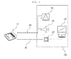
- FIG. 2 illustrates a warning system according to an exemplary embodiment.
- An instrument cluster (hereinafter, will be referred to as an IC) 20 includes a warning device notifying a user that the equipment is abnormal or is in a danger, a display device 28 providing information regarding operating conditions and error messages to the user, and an IC CPU 22 controlling the warning device and the display device.
- the warning device may include a warning light generator 26, a warning sound generator 24, a vibrator, and so on. Accordingly, the IC 20 is an assembly of devices, including the warning device, the display device, and the IC CPU.
- the master ECU 10 and the IC 20 control the display device 28 and the warning device using a communication channel allowing for two-way communications.
- the communication channel is a channel typically allowing two-way communications.
- the master ECU transmits drawing data and control commands to the IC CPU through the communication channel 30.
- the IC CPU may control the display device, the warning light generator, the warning sound generator, the vibrator, and so on.
- the master ECU is connected to the IC CPU through the communication channel and is connected to at least one of the warning light generator, the warning sound generator, and the vibrator through a hardware channel.
- the master ECU may control the operation of the warning device through the IC CPU.
- the master ECU may include an abnormality detection module periodically monitoring the validity of data through the communication channel and the responses of the warning device and the IC CPU and an on/off module operating the warning device.
- the master ECU can control the on/off module to directly operate the warning device through the hardware channel 40.
- the master ECU can control the warning device of the IC even when the master ECU cannot control the IC through the communication channel due to an abnormality in the communication channel between the master ECU and the IC CPU.
- the abnormality detection module can monitor the validity of data through the communication channel, the response of the warning device, and the response of the IC CPU using a specific method. This is intended to continuously check whether or not the warning device, the IC CPU, and the communication channel operate properly.
- the abnormality detection module can monitor the validity of data through the communication channel and the responses of the warning device and the IC CPU using at least one method selected from among checksum, cyclic redundancy check (CRC), parity bit, and message acknowledgement methods.
- CRC cyclic redundancy check
- data can be transmitted and received between the master ECU and the IC CPU through the communication channel using a variety of methods.
- data can be transmitted and received through the communication channel using at least one method selected from among CAN, SPI, LIN, RS232, RS422, and RS485.
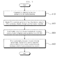
- FIG. 3 illustrates a warning method according to an exemplary embodiment.
- the warning method of notifying a user of an abnormality of the equipment when at least one of the warning device, the IC CPU, and the communication channel is abnormal may include the following steps.
- the abnormality detection module can monitor the validity of data through the communication channel and the responses of the warning device and the IC CPU using at least one method selected from among checksum, CRC, parity bit, and message acknowledgement methods.
- data can be transmitted and received through the communication channel using at least one method selected from among CAN, SPI, LIN, RS232, RS422, and RS485.
Landscapes
- Engineering & Computer Science (AREA)
- Mechanical Engineering (AREA)
- Transportation (AREA)
- Chemical & Material Sciences (AREA)
- Combustion & Propulsion (AREA)
- Automation & Control Theory (AREA)
- Physics & Mathematics (AREA)
- General Physics & Mathematics (AREA)
- Human Computer Interaction (AREA)
- Multimedia (AREA)
- Quality & Reliability (AREA)
- Computer Networks & Wireless Communication (AREA)
- Signal Processing (AREA)
- Debugging And Monitoring (AREA)
- Instrument Panels (AREA)
- Alarm Systems (AREA)
Abstract
Description
- The present disclosure relates to a system for warning a user that equipment is abnormal.
- In conventional technologies, present is a warning system designed to prevent accidents by detecting voltages and currents supplied to a variety of devices provided in vehicles and warning that any one of the devices malfunctions. In this regard, a warning system may be required to include: a sensing means for detecting currents and voltages applied to a variety of electronic devices provided in a vehicle; a control means for controlling the overall operation to determine the statuses of the variety of electronic devices provided in the vehicle by analyzing signals from the sensing means; a warning means for displaying the statuses of the vehicle based on signals from the control means and generating warning signals; and an extension means configured to be controlled in response to signals from the control means, the extension means allowing a variety of devices to be added to the warning system on a user's request. The major object of the warning system is to reliably supply currents and voltages to the electronic devices of the vehicle and prevent erroneous operations due to malfunctions, thereby preventing a variety of accidents that would otherwise be caused by erroneous operations, by using these means.
- However, in this warning system, and the control means for instructing the sensing means for detecting currents and voltages and the warning apparatus are connected with the warning apparatus by way of software. When communications are inactive due to a communication channel malfunctioning or being abnormal, it is difficult to recognize the malfunction and the status of the vehicle.
- That is, in a system in which a warning apparatus receives drawing data from a master electronic control unit (ECU) using communication protocol and then displays images, when a communication channel or software of the warning apparatus fails, neither a warning nor an error message may be delivered to a user. Such a situation may have serious effects on the safety of the user and the management of the equipment.
- There is required a technology allowing the master ECU to directly control the warning device without through the communication channel when there are errors in an instrument cluster (IC), software, or the communication channel between the master ECU and a warning apparatus.
- The present disclosure has been made keeping the above problems which may occur in the prior art in consideration, and the present disclosure proposes a separate hardware (H/W) channel to be added such that a master ECU can directly control a warning device within an IC. When an abnormality detection module detects an abnormality in communications between the IC and the master ECU, the master ECU sends a warning signal directly to the warning device through the separate hardware channel to directly operate the warning device of the IC.
- According to the present disclosure, although the master ECU controls the IC through the communication channel, and thus, when the communication channel or the IC malfunctions, information regarding the equipment is not provided to the user in a conventional way, a warning message can be sent to a user through the separate hardware channel connected to the warning device. It is thereby possible to improve the safety of the user and the reliability of the equipment.
-
-
FIG. 1 illustrates a warning system of the prior art; -
FIG. 2 illustrates a warning system according to an exemplary embodiment; and -
FIG. 3 illustrates a warning method according to an exemplary embodiment. - The present disclosure proposes a warning system including a warning device, a display device, an instrument cluster central processing unit (IC CPU) controlling the warning device and the display device, and a master electronic control unit (ECU), wherein the master ECU can directly control the warning device using a separate hardware channel even when communications between the master ECU and the IC CPU malfunction.
- Hereinafter, reference will be made to the present disclosure in conjunction with the accompanying drawings.
- The following embodiments are provided by way of specific examples so that a person having ordinary skill in the art to which the present disclosure relates could easily put the present disclosure into practice, and should not be construed as limiting the scope of the present disclosure.
- Descriptions of specific parts unrelated to the present disclosure will be omitted. Throughout this document, the same reference numerals and symbols will be used to designate the same or like components.
- Throughout the entirety of the specification and the appended Claims, the terms "comprise," "include," "have," and any variations thereof used herein are intended to cover a non-exclusive inclusion unless explicitly described to the contrary.
-
FIG. 1 illustrates a warning system of the prior art. - In the prior art, it has been typical that a master ECU and an instrument cluster send and receive drawing data therebetween through a communication channel, and that the master ECU transmits a warning signal to the instrument cluster to give a safety-related warning. However, in this system, when the communication channel malfunctions, the master ECU can neither notice an abnormality in the instrument cluster nor cope with the abnormality, which is problematic.
-
FIG. 2 illustrates a warning system according to an exemplary embodiment. - An instrument cluster (hereinafter, will be referred to as an IC) 20 includes a warning device notifying a user that the equipment is abnormal or is in a danger, a
display device 28 providing information regarding operating conditions and error messages to the user, and anIC CPU 22 controlling the warning device and the display device. The warning device may include awarning light generator 26, awarning sound generator 24, a vibrator, and so on. Accordingly, theIC 20 is an assembly of devices, including the warning device, the display device, and the IC CPU. - The
master ECU 10 and theIC 20 control thedisplay device 28 and the warning device using a communication channel allowing for two-way communications. The communication channel is a channel typically allowing two-way communications. The master ECU transmits drawing data and control commands to the IC CPU through thecommunication channel 30. In response to received drawing data and control commands, the IC CPU may control the display device, the warning light generator, the warning sound generator, the vibrator, and so on. - The master ECU is connected to the IC CPU through the communication channel and is connected to at least one of the warning light generator, the warning sound generator, and the vibrator through a hardware channel. The master ECU may control the operation of the warning device through the IC CPU.
- The master ECU may include an abnormality detection module periodically monitoring the validity of data through the communication channel and the responses of the warning device and the IC CPU and an on/off module operating the warning device.
- Afterwards, when the abnormality detection module detects an abnormality in the validity of data through the communication channel or in the response of the warning device or the IC CPU, the master ECU can control the on/off module to directly operate the warning device through the
hardware channel 40. - Through this process, the master ECU can control the warning device of the IC even when the master ECU cannot control the IC through the communication channel due to an abnormality in the communication channel between the master ECU and the IC CPU.
- In the warning system according to the present disclosure, the abnormality detection module can monitor the validity of data through the communication channel, the response of the warning device, and the response of the IC CPU using a specific method. This is intended to continuously check whether or not the warning device, the IC CPU, and the communication channel operate properly.
- Specifically, the abnormality detection module can monitor the validity of data through the communication channel and the responses of the warning device and the IC CPU using at least one method selected from among checksum, cyclic redundancy check (CRC), parity bit, and message acknowledgement methods.
- In addition, data can be transmitted and received between the master ECU and the IC CPU through the communication channel using a variety of methods.
- Specifically, data can be transmitted and received through the communication channel using at least one method selected from among CAN, SPI, LIN, RS232, RS422, and RS485.
- The present disclosure also proposes a warning method corresponding to the warning system.
FIG. 3 illustrates a warning method according to an exemplary embodiment. - The warning method of notifying a user of an abnormality of the equipment when at least one of the warning device, the IC CPU, and the communication channel is abnormal may include the following steps.
-
- 1. When the equipment is detected to be in a danger or to be malfunctioning (S100), the master ECU controls the operation of the display device and the operation of the warning device including at least one of the warning sound generator, the warning light generator, and the vibrator using the IC CPU connected thereto through the communication channel (S200).
- 2. The master ECU periodically monitors the validity of data through the communication channel and the responses of the warning device and the IC CPU using the abnormality detection module (S300).
- 3. When the abnormality detection module detects an abnormality in the validity of data through the communication channel or in the response of the warning device or the IC CPU, the master ECU directly operates the warning device using the on/off module through the hardware channel connected to the warning device (S400).
- In the warning method, as in the warning system, the abnormality detection module can monitor the validity of data through the communication channel and the responses of the warning device and the IC CPU using at least one method selected from among checksum, CRC, parity bit, and message acknowledgement methods.
- In addition, in the warning method, data can be transmitted and received through the communication channel using at least one method selected from among CAN, SPI, LIN, RS232, RS422, and RS485.
- The foregoing embodiments are merely illustrative of the certain principles of the present disclosure. It is obviously possible for a person having ordinary skill in the art to modify or alter the arrangements and details described hereinabove. It is intended therefore that the scope of the present disclosure be defined by the Claims appended hereto not by the specific descriptions presented in the foregoing embodiments.
Claims (6)
- A warning system comprising:a warning device comprising at least one of a warning sound generator, a warning light generator, and a vibrator;a display device configured to notify a user of information regarding operating conditions and an error message;an instrument cluster central processing unit configured to control operations of the display device and the warning device;a master electronic control unit configured to be connected to the instrument cluster central processing unit through a communication channel and connected to at least one of the warning light generator, the warning sound generator, and the vibration through a hardware channel, the master electronic control unit controlling the operation of the warning device using the instrument cluster central processing unit,wherein the master electronic control unit comprises:an abnormality detection module periodically monitoring validity of data through the communication channel and responses of the warning device and the instrument cluster central processing unit andan on/off module operating the warning device, andwherein, when the abnormality detection module detects an abnormality in the validity of data through the communication channel or in the response of the warning device or the IC CPU, the master electronic control unit controls the on/off module to directly operate the warning device through the hardware channel.
- The warning system of claim 1, wherein the abnormality detection module monitors the validity of data through the communication channel and the responses of the warning device and the instrument cluster central processing unit using at least one method selected from among checksum, cyclic redundancy check, parity bit, and message acknowledgement methods.
- The warning system of claim 1, wherein the data is able to be transmitted and received through the communication channel using at least one method selected from among CAN, SPI, LIN, RS232, RS422, and RS485.
- A warning method comprising:controlling step in which, when equipment is detected to be in a danger or to be malfunctioning, a master electronic control unit controls an operation of a display device and an operation of a warning device including at least one of a warning sound generator, a warning light generator, and a vibrator using an instrument cluster central processing unit connected thereto through a communication channel;monitoring step in which the master electronic control unit monitors validity of data through the communication channel and responses of the warning device and the instrument cluster central processing unit using an abnormality detection module; andoperating step in which, when the abnormality detection module detects an abnormality in the validity of data through the communication channel or in the response of the warning device or the instrument cluster central processing unit, the master electronic control unit directly operates the warning device using an on/off module through the hardware channel connected to the warning device.
- The warning method of claim 4, wherein the abnormality detection module monitors the validity of data through the communication channel and the responses of the warning device and the instrument cluster central processing unit using at least one method selected from among checksum, cyclic redundancy check, parity bit, and message acknowledgement methods.
- The warning method of claim 4, wherein the data is transmitted and received through the communication channel using at least one method selected from among CAN, SPI, LIN, RS232, RS422, and RS485.
Applications Claiming Priority (1)
| Application Number | Priority Date | Filing Date | Title |
|---|---|---|---|
| PCT/KR2013/012385 WO2015102121A1 (en) | 2013-12-30 | 2013-12-30 | Apparatus for warning of occurrence of error of device |
Publications (2)
| Publication Number | Publication Date |
|---|---|
| EP3090911A1 true EP3090911A1 (en) | 2016-11-09 |
| EP3090911A4 EP3090911A4 (en) | 2017-10-25 |
Family
ID=53493459
Family Applications (1)
| Application Number | Title | Priority Date | Filing Date |
|---|---|---|---|
| EP13900802.3A Withdrawn EP3090911A4 (en) | 2013-12-30 | 2013-12-30 | Apparatus for warning of occurrence of error of device |
Country Status (4)
| Country | Link |
|---|---|
| US (1) | US9659415B2 (en) |
| EP (1) | EP3090911A4 (en) |
| CN (1) | CN105873806A (en) |
| WO (1) | WO2015102121A1 (en) |
Cited By (1)
| Publication number | Priority date | Publication date | Assignee | Title |
|---|---|---|---|---|
| WO2020020566A1 (en) * | 2018-07-26 | 2020-01-30 | Valeo Schalter Und Sensoren Gmbh | System for automatically monitored vehicle status signalling and method for monitoring a vehicle status signalling device |
Families Citing this family (6)
| Publication number | Priority date | Publication date | Assignee | Title |
|---|---|---|---|---|
| WO2017039023A1 (en) * | 2015-08-31 | 2017-03-09 | 볼보 컨스트럭션 이큅먼트 에이비 | Construction equipment buzzer sound control system |
| US12409756B2 (en) | 2017-04-05 | 2025-09-09 | H55 Sa | Aircraft monitoring system and method for electric or hybrid aircrafts |
| US11065979B1 (en) | 2017-04-05 | 2021-07-20 | H55 Sa | Aircraft monitoring system and method for electric or hybrid aircrafts |
| US10322824B1 (en) | 2018-01-25 | 2019-06-18 | H55 Sa | Construction and operation of electric or hybrid aircraft |
| CN110293841A (en) * | 2019-06-26 | 2019-10-01 | 大陆汽车车身电子系统(芜湖)有限公司 | A kind of warning message display methods and combination instrument |
| WO2023079492A1 (en) | 2021-11-05 | 2023-05-11 | H55 Sa | Information display system and method for electric or hybrid aircrafts |
Family Cites Families (10)
| Publication number | Priority date | Publication date | Assignee | Title |
|---|---|---|---|---|
| US6131051A (en) * | 1998-01-05 | 2000-10-10 | Microsoft Corporation | Interface between a base module and a detachable faceplate in an in-dash automotive accessory |
| JP3902168B2 (en) * | 2003-09-04 | 2007-04-04 | 日立建機株式会社 | Diagnostic information display system for construction machinery |
| US20050055474A1 (en) * | 2003-09-08 | 2005-03-10 | Chien-Hsin Yang | Monitor apparatus for computer system |
| KR20060084639A (en) * | 2005-01-20 | 2006-07-25 | 현대자동차주식회사 | Alternative communication device and method of integrated control unit |
| JP4353297B2 (en) * | 2007-10-17 | 2009-10-28 | トヨタ自動車株式会社 | vehicle |
| KR101241945B1 (en) * | 2007-12-14 | 2013-03-12 | 현대자동차주식회사 | In-Vehicle Network Fault Monitoring System and Method thereof |
| KR101304204B1 (en) * | 2009-03-30 | 2013-09-05 | 주식회사 만도 | apparatus to detect communication error of vehicle |
| SE535786C2 (en) * | 2010-01-19 | 2012-12-18 | Volvo Technology Corp | Dead Angle Warning System |
| CN201745445U (en) * | 2010-08-18 | 2011-02-16 | 内蒙古北方重型汽车股份有限公司 | Off-highway dump truck CAN bus combined instrument |
| US8887022B2 (en) * | 2011-03-04 | 2014-11-11 | Infineon Technologies Austria Ag | Reliable data transmission with reduced bit error rate |
-
2013
- 2013-12-30 US US15/109,329 patent/US9659415B2/en not_active Expired - Fee Related
- 2013-12-30 WO PCT/KR2013/012385 patent/WO2015102121A1/en not_active Ceased
- 2013-12-30 EP EP13900802.3A patent/EP3090911A4/en not_active Withdrawn
- 2013-12-30 CN CN201380081923.8A patent/CN105873806A/en active Pending
Cited By (5)
| Publication number | Priority date | Publication date | Assignee | Title |
|---|---|---|---|---|
| WO2020020566A1 (en) * | 2018-07-26 | 2020-01-30 | Valeo Schalter Und Sensoren Gmbh | System for automatically monitored vehicle status signalling and method for monitoring a vehicle status signalling device |
| CN112714719A (en) * | 2018-07-26 | 2021-04-27 | 法雷奥开关和传感器有限责任公司 | System for signalling for automatic monitoring of vehicle state and method for monitoring a vehicle state signalling device |
| US20210163028A1 (en) * | 2018-07-26 | 2021-06-03 | Valeo Schalter Und Sensoren Gmbh | System for automatically monitored signalling of a vehicle state and method for monitoring a vehicle state-signalling device |
| CN112714719B (en) * | 2018-07-26 | 2024-05-31 | 法雷奥开关和传感器有限责任公司 | System for automatic monitoring of vehicle status and method for monitoring vehicle status signaling device |
| US12202497B2 (en) * | 2018-07-26 | 2025-01-21 | Valeo Schalter Und Sensoren Gmbh | System for automatically monitored signalling of a vehicle state and method for monitoring a vehicle state-signalling device |
Also Published As
| Publication number | Publication date |
|---|---|
| EP3090911A4 (en) | 2017-10-25 |
| US20160328888A1 (en) | 2016-11-10 |
| US9659415B2 (en) | 2017-05-23 |
| WO2015102121A1 (en) | 2015-07-09 |
| CN105873806A (en) | 2016-08-17 |
Similar Documents
| Publication | Publication Date | Title |
|---|---|---|
| US9659415B2 (en) | Apparatus for warning of occurrence of error of device | |
| US9843523B2 (en) | Communication management apparatus and communication management method for vehicle network | |
| JP5283651B2 (en) | Control device for vehicle | |
| US10689006B2 (en) | Monitoring system for an autonomous vehicle | |
| US9087077B2 (en) | In-vehicle electronic control device | |
| CN113400937B (en) | Vehicle entertainment information display system and vehicle | |
| US20150344039A1 (en) | Vehicuar control device and fail-safe method | |
| JP7605251B2 (en) | Mobility control system, method, and program | |
| JP2014146087A (en) | Monitoring control system | |
| US9925935B2 (en) | In-vehicle communication system and in-vehicle communication method | |
| KR101173087B1 (en) | Control apparatus and control method of vehicle | |
| US8510593B2 (en) | Control apparatus | |
| CN103338991B (en) | Method and system for monitoring the function of a safety monitoring system of a control unit | |
| KR101297024B1 (en) | Method and apparatus for fault diagnosis network of car using can communication | |
| EP1843247A1 (en) | Information processing system and information processing method | |
| KR101378277B1 (en) | Ecu control and monitoring device for vechicle | |
| EP3118052B1 (en) | Train information management device | |
| KR20110101092A (en) | Monitoring system and method of vehicle and device using mobile terminal | |
| KR101078151B1 (en) | Wireless surveillance system for high current electron beam generator | |
| JP2007026241A (en) | Abnormality monitoring method and control device using the same | |
| KR101655685B1 (en) | Method for diagnosing combined controller in vehicle | |
| JP3962956B6 (en) | Information processing apparatus and information processing method | |
| HK1233225A1 (en) | Train information management device |
Legal Events
| Date | Code | Title | Description |
|---|---|---|---|
| PUAI | Public reference made under article 153(3) epc to a published international application that has entered the european phase |
Free format text: ORIGINAL CODE: 0009012 |
|
| 17P | Request for examination filed |
Effective date: 20160630 |
|
| AK | Designated contracting states |
Kind code of ref document: A1 Designated state(s): AL AT BE BG CH CY CZ DE DK EE ES FI FR GB GR HR HU IE IS IT LI LT LU LV MC MK MT NL NO PL PT RO RS SE SI SK SM TR |
|
| AX | Request for extension of the european patent |
Extension state: BA ME |
|
| DAX | Request for extension of the european patent (deleted) | ||
| RIC1 | Information provided on ipc code assigned before grant |
Ipc: B60W 50/04 20060101ALI20170914BHEP Ipc: B60R 21/015 20060101ALI20170914BHEP Ipc: B60R 16/02 20060101ALI20170914BHEP Ipc: B60W 50/02 20120101AFI20170914BHEP |
|
| A4 | Supplementary search report drawn up and despatched |
Effective date: 20170922 |
|
| STAA | Information on the status of an ep patent application or granted ep patent |
Free format text: STATUS: REQUEST FOR EXAMINATION WAS MADE |
|
| STAA | Information on the status of an ep patent application or granted ep patent |
Free format text: STATUS: THE APPLICATION IS DEEMED TO BE WITHDRAWN |
|
| 18D | Application deemed to be withdrawn |
Effective date: 20180421 |