EP3090804A1 - Apparatus and method for controlling droplet - Google Patents
Apparatus and method for controlling droplet Download PDFInfo
- Publication number
- EP3090804A1 EP3090804A1 EP16168431.1A EP16168431A EP3090804A1 EP 3090804 A1 EP3090804 A1 EP 3090804A1 EP 16168431 A EP16168431 A EP 16168431A EP 3090804 A1 EP3090804 A1 EP 3090804A1
- Authority
- EP
- European Patent Office
- Prior art keywords
- droplet
- dimple
- flexible substrate
- vacuum
- vacuum tip
- Prior art date
- Legal status (The legal status is an assumption and is not a legal conclusion. Google has not performed a legal analysis and makes no representation as to the accuracy of the status listed.)
- Granted
Links
Images


Classifications
-
- B—PERFORMING OPERATIONS; TRANSPORTING
- B01—PHYSICAL OR CHEMICAL PROCESSES OR APPARATUS IN GENERAL
- B01L—CHEMICAL OR PHYSICAL LABORATORY APPARATUS FOR GENERAL USE
- B01L3/00—Containers or dishes for laboratory use, e.g. laboratory glassware; Droppers
- B01L3/50—Containers for the purpose of retaining a material to be analysed, e.g. test tubes
- B01L3/502—Containers for the purpose of retaining a material to be analysed, e.g. test tubes with fluid transport, e.g. in multi-compartment structures
-
- B—PERFORMING OPERATIONS; TRANSPORTING
- B01—PHYSICAL OR CHEMICAL PROCESSES OR APPARATUS IN GENERAL
- B01L—CHEMICAL OR PHYSICAL LABORATORY APPARATUS FOR GENERAL USE
- B01L3/00—Containers or dishes for laboratory use, e.g. laboratory glassware; Droppers
- B01L3/50—Containers for the purpose of retaining a material to be analysed, e.g. test tubes
- B01L3/502—Containers for the purpose of retaining a material to be analysed, e.g. test tubes with fluid transport, e.g. in multi-compartment structures
- B01L3/5027—Containers for the purpose of retaining a material to be analysed, e.g. test tubes with fluid transport, e.g. in multi-compartment structures by integrated microfluidic structures, i.e. dimensions of channels and chambers are such that surface tension forces are important, e.g. lab-on-a-chip
- B01L3/50273—Containers for the purpose of retaining a material to be analysed, e.g. test tubes with fluid transport, e.g. in multi-compartment structures by integrated microfluidic structures, i.e. dimensions of channels and chambers are such that surface tension forces are important, e.g. lab-on-a-chip characterised by the means or forces applied to move the fluids
-
- B—PERFORMING OPERATIONS; TRANSPORTING
- B01—PHYSICAL OR CHEMICAL PROCESSES OR APPARATUS IN GENERAL
- B01L—CHEMICAL OR PHYSICAL LABORATORY APPARATUS FOR GENERAL USE
- B01L3/00—Containers or dishes for laboratory use, e.g. laboratory glassware; Droppers
- B01L3/50—Containers for the purpose of retaining a material to be analysed, e.g. test tubes
- B01L3/502—Containers for the purpose of retaining a material to be analysed, e.g. test tubes with fluid transport, e.g. in multi-compartment structures
- B01L3/5027—Containers for the purpose of retaining a material to be analysed, e.g. test tubes with fluid transport, e.g. in multi-compartment structures by integrated microfluidic structures, i.e. dimensions of channels and chambers are such that surface tension forces are important, e.g. lab-on-a-chip
- B01L3/502769—Containers for the purpose of retaining a material to be analysed, e.g. test tubes with fluid transport, e.g. in multi-compartment structures by integrated microfluidic structures, i.e. dimensions of channels and chambers are such that surface tension forces are important, e.g. lab-on-a-chip characterised by multiphase flow arrangements
- B01L3/502784—Containers for the purpose of retaining a material to be analysed, e.g. test tubes with fluid transport, e.g. in multi-compartment structures by integrated microfluidic structures, i.e. dimensions of channels and chambers are such that surface tension forces are important, e.g. lab-on-a-chip characterised by multiphase flow arrangements specially adapted for droplet or plug flow, e.g. digital microfluidics
- B01L3/502792—Containers for the purpose of retaining a material to be analysed, e.g. test tubes with fluid transport, e.g. in multi-compartment structures by integrated microfluidic structures, i.e. dimensions of channels and chambers are such that surface tension forces are important, e.g. lab-on-a-chip characterised by multiphase flow arrangements specially adapted for droplet or plug flow, e.g. digital microfluidics for moving individual droplets on a plate, e.g. by locally altering surface tension
-
- B—PERFORMING OPERATIONS; TRANSPORTING
- B01—PHYSICAL OR CHEMICAL PROCESSES OR APPARATUS IN GENERAL
- B01L—CHEMICAL OR PHYSICAL LABORATORY APPARATUS FOR GENERAL USE
- B01L3/00—Containers or dishes for laboratory use, e.g. laboratory glassware; Droppers
- B01L3/50—Containers for the purpose of retaining a material to be analysed, e.g. test tubes
- B01L3/508—Rigid containers without fluid transport within
- B01L3/5088—Rigid containers without fluid transport within confining liquids at a location by surface tension, e.g. virtual wells on plates, wires
-
- B—PERFORMING OPERATIONS; TRANSPORTING
- B01—PHYSICAL OR CHEMICAL PROCESSES OR APPARATUS IN GENERAL
- B01L—CHEMICAL OR PHYSICAL LABORATORY APPARATUS FOR GENERAL USE
- B01L2200/00—Solutions for specific problems relating to chemical or physical laboratory apparatus
- B01L2200/06—Fluid handling related problems
-
- B—PERFORMING OPERATIONS; TRANSPORTING
- B01—PHYSICAL OR CHEMICAL PROCESSES OR APPARATUS IN GENERAL
- B01L—CHEMICAL OR PHYSICAL LABORATORY APPARATUS FOR GENERAL USE
- B01L2200/00—Solutions for specific problems relating to chemical or physical laboratory apparatus
- B01L2200/06—Fluid handling related problems
- B01L2200/0642—Filling fluids into wells by specific techniques
-
- B—PERFORMING OPERATIONS; TRANSPORTING
- B01—PHYSICAL OR CHEMICAL PROCESSES OR APPARATUS IN GENERAL
- B01L—CHEMICAL OR PHYSICAL LABORATORY APPARATUS FOR GENERAL USE
- B01L2200/00—Solutions for specific problems relating to chemical or physical laboratory apparatus
- B01L2200/10—Integrating sample preparation and analysis in single entity, e.g. lab-on-a-chip concept
-
- B—PERFORMING OPERATIONS; TRANSPORTING
- B01—PHYSICAL OR CHEMICAL PROCESSES OR APPARATUS IN GENERAL
- B01L—CHEMICAL OR PHYSICAL LABORATORY APPARATUS FOR GENERAL USE
- B01L2300/00—Additional constructional details
- B01L2300/12—Specific details about materials
- B01L2300/123—Flexible; Elastomeric
-
- B—PERFORMING OPERATIONS; TRANSPORTING
- B01—PHYSICAL OR CHEMICAL PROCESSES OR APPARATUS IN GENERAL
- B01L—CHEMICAL OR PHYSICAL LABORATORY APPARATUS FOR GENERAL USE
- B01L2400/00—Moving or stopping fluids
- B01L2400/04—Moving fluids with specific forces or mechanical means
- B01L2400/0403—Moving fluids with specific forces or mechanical means specific forces
- B01L2400/0457—Moving fluids with specific forces or mechanical means specific forces passive flow or gravitation
-
- B—PERFORMING OPERATIONS; TRANSPORTING
- B01—PHYSICAL OR CHEMICAL PROCESSES OR APPARATUS IN GENERAL
- B01L—CHEMICAL OR PHYSICAL LABORATORY APPARATUS FOR GENERAL USE
- B01L2400/00—Moving or stopping fluids
- B01L2400/04—Moving fluids with specific forces or mechanical means
- B01L2400/0475—Moving fluids with specific forces or mechanical means specific mechanical means and fluid pressure
Definitions
- the present disclosure herein relates to an apparatus and method for controlling a droplet, and more particularly, to an apparatus and method for freely controlling movement, stop, and mixing of a droplet.
- a lab-on-a-chip (LOC) technology has advantages in that chemical synthesis and analysis processes are performed in one chip by using a small amount of sample to improve efficiency and accuracy.
- the LOC technology is in the spotlight as a technology that is suitable for next-generation fields such as nano-bio technologies and nano-bio medical technologies.
- technologies for manufacturing a microstructure and microfluidic adjusting and droplet control technologies for inducing and adjusting reaction of a sample with a reagent in the manufactured microstructure are required.
- the droplet control technology is based on a method electrowetting, a method using dielectricphoresis, a method using magnetic force, a light-induced actuation method, and the like.
- the sample since external stimulation is required for controlling a droplet, the sample may be damaged, and also, the degree of freedom of the control may be deteriorated due to the complex system. In addition, the sample may be contaminated and damaged.
- a new droplet control technology that is applicable to fields such as medicine and biotechnology by minimizing the stimulation and contamination, which cause the damage of the sample, is needed.
- the present disclosure provides an apparatus for controlling a droplet, which has a high degree of freedom in droplet control, does not contaminate/damage a sample, and is capable of being repeatedly used for a long time, and a method for controlling the droplet.
- the present disclosure also provide an apparatus for controlling a droplet, which is capable of adjusting a diameter of a vacuum tip and a degree of vacuum in the vacuum tip to freely adjust a size and shape of a dimple and to control a droplet volume.
- An embodiment of the inventive concept provides an apparatus for controlling a droplet, the apparatus including: a flexible substrate having a hydrophobic or oleophobic surface; and a dimple formation unit configured to locally deform a bottom surface of the flexible substrate, thereby forming a dimple.
- the dimple formation unit may include a vacuum tip, which suctions the bottom surface of the flexible substrate to locally mechanically deform the bottom surface.
- the vacuum tip may have a structure of a circular shaped cross section.
- the vacuum tip may contact the bottom surface of the flexible substrate.
- the dimple formation unit may include a vacuum adjusting part configured to adjust a pressure of a space between the vacuum tip and the flexible substrate.
- the vacuum adjusting part may adjust a degree of vacuum of the vacuum tip to adjust a shape of the dimple.
- the dimple may have a size that varies according to an inner diameter of the vacuum tip.
- the apparatus may further include a driving unit configured to move the vacuum tip at a lower side of the flexible substrate.
- the driving unit may move the vacuum tip to move the droplet within the dimple on the flexible substrate.
- a pattern part having a hydrophilic or oleophilic property may be disposed in the form of a predetermined pattern on a top surface of the flexible substrate.
- the pattern part when the flexible substrate has the hydrophobic surface, the pattern part may have the hydrophilic property, and when the flexible substrate has the oleophobic surface, the pattern part may have the oleophilic property.
- the driving unit may move the vacuum tip along the predetermined pattern.
- the dimple formation unit may fix the droplet within the dimple.
- a method for controlling a droplet includes: locally deforming a flexible substrate having a hydrophobic or oleophobic surface by using a dimple formation unit to form a dimple; and moving the dimple formation unit to move the droplet within the dimple.
- the forming of the dimple may include suctioning a bottom surface of the flexible substrate by using a vacuum tip of the dimple formation unit to locally mechanically deform the flexible substrate.
- a degree of vacuum of the vacuum tip may be adjusted to adjust a shape of the dimple.
- An apparatus for controlling a droplet according to embodiments of the inventive concept induces mechanical deformation (bending) on a hydrophobic or oleophobic surface of a flexible substrate to locally form a dimple, thereby controlling the droplet. That is, the apparatus for controlling the droplet according to the embodiments of the inventive concept may form a hydrophobic or oleophobic surface on a thin flexible surface that is stretchable or bendable to apply mechanical force on the hydrophobic or oleophobic surface and thus to locally form a dimple, thereby freely controlling movement, stop, and mixing of the droplet.
- FIG. 1 is a partial cut-away perspective view of an apparatus for controlling a droplet according to an embodiment of the inventive concept.
- an apparatus 100 for controlling a droplet according to an embodiment of the inventive concept includes a flexible substrate 120, a dimple formation unit 140, a driving unit 160, and a control unit 180.
- a bendable or stretchable substrate having flexibility may be provided as the flexible substrate 120.
- the flexible substrate may have flexibility that is enough to locally form a dimple on a surface thereof.
- the flexible substrate 120 may have a hydrophobic surface on a top surface thereof. Thus, a droplet 10 may be well slid along the surface of the flexible substrate 120.
- the flexible substrate 120 may be horizontally supported by a holder 20. That is, the flexible substrate 120 may be provided in an opening that is defined in a central portion of the holder 20. A space through which a vacuum tip of the dimple formation unit 140 is movable may be defined under the flexible substrate 120 by the holder 20.
- a water drop, an oil drop, or other various kinds of fluids may be used as the droplet 10.
- the droplet 10 may include various biomaterials or chemical materials, which are objects to be analyzed, such as a DNA, protein, an antibody, a sugar chain, a cell, a neuron, and blood.
- the droplet 10 may be provided to the surface of the flexible substrate 120 through a sample supply part 30.
- the sample supply part 30 may apply an oil pressure to a sample supply tube by using a micropump to supply a minimum amount of droplet 10 required for analysis onto the surface of the flexible substrate 120.
- the flexible substrate 120 may have a hydrophobic or oleophobic surface having a contact angle of about 90° or more with respect to the droplet (e.g., water drop or oil drop) on the top surface thereof. More particularly, the flexible substrate 120 may have a superhydrophobic or superoleophobic surface having a contact angle of about 150° or more with respect to the droplet.
- the droplet e.g., water drop or oil drop
- the flexible substrate 120 may have a superhydrophobic or superoleophobic surface having a contact angle of about 150° or more with respect to the droplet.
- the hydrophobic or oleophobic surface may be formed through various methods in which the flexible substrate 120 is manufactured using a hydrophobic or oleophobic material, hydrophobic or oleophobic coating treatment is performed on the surface of the flexible substrate 120, or a nanostructure for forming the hydrophobic or oleophobic surface is formed on the surface of the flexible substrate 120.
- FIGS. 2 and 3 are views for explaining an operation of the dimple formation unit 140 constituting the apparatus for controlling the droplet according to an embodiment of the inventive concept.
- the dimple formation unit 140 may locally deform a bottom surface of the flexible substrate 120 to form a dimple 142 as illustrated in FIG. 3 .
- the dimple formation unit 140 may be provided for fixing the droplet 10 within the dimple 142.
- the dimple formation unit 140 may include a vacuum tip 144.
- the vacuum tip 144 may contact the bottom surface of the flexible substrate 120 to suction the bottom surface of the flexible substrate 120, thereby locally deforming the flexible substrate 120.
- the vacuum tip 144 may have an approximately cylindrical shape and also have a tip structure having a circular cross-section on an upper portion thereof.
- the dimple 142 may have a shape that is recessed in a circular puddle shape.
- the droplet 10 may be fixed within the dimple 142.
- the dimple formation unit 140 may include a vacuum adjusting part 146 for adjusting a degree of vacuum of the vacuum tip 144.
- the vacuum adjusting part 146 may adjust the degree of vacuum of the vacuum tip 144 to adjust a size and shape of the dimple 142.
- the vacuum adjusting part 146 may be provided as a vacuum pump.
- a space between the vacuum tip 144 and the flexible substrate 120 may become a vacuum state or a low vacuum state that is less than an external pressure (e.g., an atmospheric pressure).
- an external pressure e.g., an atmospheric pressure
- the dimple may be locally formed on the flexible substrate 120 by a difference in pressure between the top and bottom surfaces of the flexible substrate 120.
- the vacuum tip 144 may have a size corresponding to that of the dimple 142.
- the vacuum tip 144 having an opening with various diameters may be replaced to adjust the size and shape of the dimple 142 and thus control the droplet volume.
- the droplet 10 is fixed within the structure of the dimple 142 by characteristics of the hydrophobic or oleophobic surface.
- the flexible substrate 120 may return to its original shape by superior flexibility thereof as illustrated in FIG. 2 .
- FIG. 4 is a view illustrating a state in which the droplet 10 moves by the driving unit 160 constituting the apparatus for controlling the droplet according to an embodiment of the inventive concept.
- the driving unit 160 may move the dimple formation unit 140 at a lower side of the flexible substrate 120 while the dimple formation unit 140 performs the suctioning operation.
- the driving unit 160 may move the droplet 10 within the dimple 142 on the flexible substrate 120.
- the driving unit 160 may be provided in the form of an XY stage.
- the driving unit 160 may be provided as various mechanical mechanisms such as a driving motor or a hydraulic cylinder.
- the driving unit 160 includes a first guide member 162, a second guide member 166, and a movable member 164.
- the first guide member 162 is disposed in a first direction to drive the second guide member 166 in the first direction.
- the second guide member 166 is disposed in a second direction perpendicular to the first direction to move in the second direction along the first guide member 162.
- the movable member 164 may be moved in the first direction along the first guide member 162 together with the second guide member 166 and moved in the second direction along the second guide member 166.
- An elevation member for elevating the vacuum tip 144 may be disposed on the movable member 164. Thus, the vacuum tip 144 may be driven along X-Y-Z axes.
- the control unit 180 controls the dimple formation unit 140 and the driving unit 160.
- the control unit 180 may transmit a command to the dimple formation unit 140 and the driving unit 160 according to a user's input through preset program or a user interface unit (e.g., a mouse, a keyboard, a touch pad, and the like).
- the dimple formation unit 140 may start or stop the vacuum suction thereof according to the command of the control unit 180.
- the driving unit 160 moves a position of the vacuum tip 144 according to the command of the control unit 180.
- an inclination of a side surface of the dimple 142 may be controlled at an angle that is greater than a critical inclination at which the droplet 10 is rolled down by the gravity.
- the movement of the droplet 10 may be freely controlled according to a path along which the vacuum tip 144 is moved.
- the driving unit 160 may operate to move the droplet 10 to an analysis part 40 in the state in which the dimple 142 is formed by the dimple formation unit 140. After the droplet 10 is completely analyzed by the analysis part 40, the droplet 10 may be moved to a sample discharge part 50. The analyzed droplet 10 may be discharged through the sample discharge part 50.
- the droplet manipulation technologies are developed by using a mechanical valve, heat, electromagnetic fields, and an acoustic wave as a manipulation unit, the droplet manipulation technologies may be complicated in use, and an additional additive may be required. Thus, it may be difficult to accurately adjust a target droplet, and also, the droplet may be unintentionally lost or contaminated during the manipulation.
- a remaining droplet may not exist on a moving path along which the droplet 10 passes after the droplet 10 is moved by the movement of the structure of the dimple 142.
- the apparatus for controlling the droplet since the loss of the droplet 10 and the reaction with the surface of the flexible substrate 120 during the movement of the droplet 10 are reduced, when the apparatus for controlling the droplet according to an embodiment of the inventive concept is applied to a lap-on-a-chip (LOC) technology that is necessary for various syntheses and analyses, the apparatus for controlling the droplet may have great advantages.
- LOC lap-on-a-chip
- the apparatus for controlling the droplet according to the current embodiment may be suitable for utilization in nanoparticle and bio fields, to which it is difficult to apply the existing technologies, because the apparatus for controlling the droplet is simple to use and does not cause deterioration of the sample.
- the vacuum tip 144 may be adjusted in diameter to adjust a size and shape of the structure of the dimple 142, thereby controlling the droplet volume. Also, if several vacuum tips are provided to be independently moved, a plurality of droplets may be controlled at the same time, and thus, the apparatus for controlling the droplet may be easily applied and expanded to various fields.
- the droplet since it is unnecessary to designate an additional path along which the droplet is moved or add an additive, unlike the existing methods, the droplet may be freely moved, and particularly, the contamination and loss of the droplet may be significantly reduced by using the superhydrophobic or superoleophobic surface.
- FIG. 5 is a flowchart of a method for controlling a droplet according to an embodiment of the inventive concept.
- a method for controlling a droplet according to an embodiment of the inventive concept includes a process (S10) of locally deforming a flexible substrate 120 having a hydrophobic or oleophobic surface by using a vacuum tip to form a dimple and a process of moving the vacuum tip to move a droplet 10 within the dimple 142.
- a dimple formation unit 140 may suction a bottom surface of the flexible substrate 120 by using a vacuum tip 144 to locally mechanically deform the flexible substrate 120.
- the dimple formation unit 140 may adjust a degree of vacuum of the vacuum tip 144 to adjust a shape of the dimple 142.
- the vacuum tip 144 may stand by a position at which the droplet is initially supplied.
- the process of supplying the droplet 10 to the flexible substrate 120 may be performed before or after the dimple is formed on the flexible substrate 120.
- the droplet 10 may be efficiently moved on the surface of the flexible substrate 120 by movement of a structure of a dimple 142 due to the movement of the vacuum tip 144.
- the reciprocating movement of the vacuum tip 144 may be repeatedly performed to mix the droplet 10, or the vacuum tip 144 may be moved to move the droplet 10 or mix the droplet 10 with other droplets.
- a liquid does not remain on a path, along which the droplet 10 passes, by hydrophobic or oleophobic surface characteristics while the droplet 10 is moved.
- FIG. 6 is a graph illustrating a variation in shape of the dimple depending on an inner diameter of the vacuum tip.
- the dimple may increase in width and depth.
- the dimple may be adjusted in shape according to the inner diameter of the vacuum tip, and also, the droplet may be adjusted in volume.
- FIG. 7 is a graph illustrating a volume of the droplet that is controllable according to a width of the vacuum tip.
- the volume of the droplet may be adjusted according to the width of the vacuum tip in consideration of the volume of the controllable droplet, or a vacuum tip having an adequate diameter may be used according to the volume of the droplet.
- the droplet may be movable by surface tension thereof.
- the droplet since an additional pattern or channel for designating the path of the droplet is not required, the droplet may be freely moved on the surface of the flexible substrate. In addition, since a loss of the droplet is less, the droplet may be controlled based on a minimum amount of sample.
- the droplet control technologies according to the current embodiment since possibility of the contamination/deterioration of the sample may be low, technologies for real time/non-real time detection of a sample to be analyzed and RNA transfer, which are difficult to be realized in the existing LOC, may be successively realized.
- the drop control technologies according to the current embodiment may be suitable for application fields including chemical synthesis and cell culture and various nanoparticle and bio fields.
- the droplet control technology since electrical/chemical stimulation is unnecessary, unlike the existing droplet control technologies, and the droplet control technology is applicable to the most LOC application fields including a microreactor, a bio chemical sensor, bio electronics, and laboratory medicine, its industrial applicability may be high.
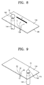
- FIG. 8 is a perspective view illustrating a portion of an apparatus for controlling a droplet according to another embodiment of the inventive concept.
- duplicated description with respect to the same or corresponding component as that according to the foregoing embodiment may be omitted.
- FIG. 8 An embodiment of FIG. 8 is different from the foregoing embodiment in that a pattern part 126 having a hydrophilic or oleophilic property is formed on a top surface of a flexible substrate 120.
- the flexible substrate 120 may be provided as a flexible substrate such as, for example, polydimethylsiloxane (PDMS).
- PDMS polydimethylsiloxane
- the flexible substrate 120 may be supported by the holder in a state in which the substrate 120 is strainedly pulled and thus be horizontally disposed.
- the pattern part 126 may have a hydrophobic property.
- the pattern part 126 may have an oleophilic property.
- the pattern part 126 may have a hydrophilic or oleophilic surface having a contact angle of about 90° or less with respect to a droplet (water drop or oil drop).
- the pattern part 126 may have a superhydrophilic or superoleophilic surface having a contact angle of about 30° or less with respect to the droplet.
- a driving unit may move a vacuum tip 144 along a predetermined pattern in a first direction D.
- FIG. 9 is a view illustrating a state in which a microdroplet pattern 12 is formed on the flexible substrate according to the embodiment of FIG. 8 . Referring to FIGS. 8 and 9 , as a vacuum tip 144 is moved along a pattern of a pattern part 126, a dimple 142 and a droplet 10 are moved along the pattern part 126.
- a flexible substrate 120 may have a hydrophobic surface 124, and the pattern part 126 may have a hydrophilic property. While the droplet 10 is moved along the pattern of the pattern part 126, a portion of the droplet 10 may remain on the pattern part 126 having the hydrophilic property, and a microdroplet pattern 12 as illustrated in FIG. 9 may be obtained.
- the flexible substrate may have an oleophobic surface 124, and the pattern may have an oleophilic property. While the droplet 10 is moved along the pattern of the pattern part 126, a portion of the droplet 10 may remain on the pattern part 126 having the oleophilic property, and a microdroplet pattern 12 as illustrated in FIG. 9 may be obtained.
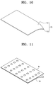
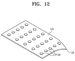
- FIGS. 10 to 12 are views illustrating a process of manufacturing the flexible substrate according to the embodiment of FIG. 8 .
- a bonding material is sprayed on a substrate 122 having flexibility
- hydrophobic or oleophobic nanoparticles may be applied to obtain a substrate 120 having a hydrophobic or oleophobic surface 124.
- a pattern mask M may be disposed on the flexible substrate 120, and oxygen plasma treatment is performed. Then, the mask pattern M may be removed to form a pattern part 126 having the hydrophilic or oleophilic property in the form of a predetermined pattern on a top surface of the flexible substrate 120, as illustrated in FIG. 12 .
- the microdroplet pattern may be formed.
- the apparatus for controlling the droplet according to the current embodiment may be applicable to bio diagnostic fields such as multi bio-detection fields or other various fields in the way that the microdroplet pattern is used as a reagent, or the microdroplet pattern reacts with a reagent formed on the hydrophilic or oleophilic pattern.
- the pattern is formed on the hydrophobic or oleophobic flexible substrate by using the oxygen plasma treatment
- an embodiment of the inventive concept is not limited thereto.
- the pattern part may be formed through various methods. For example, in the state in which the pattern mask is disposed on the substrate having the hydrophilic or oleophilic surface, hydrophobic or oleophobic coating may be performed on the substrate to form the pattern. Alternatively, a hydrophilic or oleophilic material may be applied to the hydrophobic or oleophobic substrate to form the pattern.
- the apparatus for controlling the droplet which has the high degree of freedom in droplet control, does not contaminate/damage the sample, and is capable of being repeatedly used for a long time, and the method for controlling the droplet may be provided.
- the vacuum tip may be adjusted in diameter and degree of vacuum to freely adjust the size and shape of the dimple and control the droplet volume.
Landscapes
- Chemical & Material Sciences (AREA)
- Health & Medical Sciences (AREA)
- Analytical Chemistry (AREA)
- Clinical Laboratory Science (AREA)
- Chemical Kinetics & Catalysis (AREA)
- General Health & Medical Sciences (AREA)
- Hematology (AREA)
- Dispersion Chemistry (AREA)
- Physical Or Chemical Processes And Apparatus (AREA)
- Automatic Analysis And Handling Materials Therefor (AREA)
- Life Sciences & Earth Sciences (AREA)
- Molecular Biology (AREA)
Abstract
Description
- The present disclosure herein relates to an apparatus and method for controlling a droplet, and more particularly, to an apparatus and method for freely controlling movement, stop, and mixing of a droplet.
- A lab-on-a-chip (LOC) technology has advantages in that chemical synthesis and analysis processes are performed in one chip by using a small amount of sample to improve efficiency and accuracy. Thus, the LOC technology is in the spotlight as a technology that is suitable for next-generation fields such as nano-bio technologies and nano-bio medical technologies. To manufacture an LOC, technologies for manufacturing a microstructure and microfluidic adjusting and droplet control technologies for inducing and adjusting reaction of a sample with a reagent in the manufactured microstructure are required.
- Existing representative fluidic adjusting technologies have been studied by a method in which a fluid continuously flows through a microchannel constituted by a micropump, a valve, and a mixer. However, the development speed of the fluidic adjusting technologies is slowed down due to fundamental limitations such as a complex mechanism, a limited flow rate, and a limitation of reconfigurability in the fluidic adjusting technologies. As an alternative method, an open LOC based on a droplet control technology which is capable of quantifying and controlling a much smaller amount of sample and inducing rapid reaction is being magnified as a new measure.
- So far, the droplet control technology is based on a method electrowetting, a method using dielectricphoresis, a method using magnetic force, a light-induced actuation method, and the like. However, since external stimulation is required for controlling a droplet, the sample may be damaged, and also, the degree of freedom of the control may be deteriorated due to the complex system. In addition, the sample may be contaminated and damaged. Thus, a new droplet control technology that is applicable to fields such as medicine and biotechnology by minimizing the stimulation and contamination, which cause the damage of the sample, is needed.
- The present disclosure provides an apparatus for controlling a droplet, which has a high degree of freedom in droplet control, does not contaminate/damage a sample, and is capable of being repeatedly used for a long time, and a method for controlling the droplet.
- The present disclosure also provide an apparatus for controlling a droplet, which is capable of adjusting a diameter of a vacuum tip and a degree of vacuum in the vacuum tip to freely adjust a size and shape of a dimple and to control a droplet volume.
- The objects of the inventive concept are not limited to the abovementioned objects. Other objects thereof will be understandable by those skilled in the art from the following descriptions.
- An embodiment of the inventive concept provides an apparatus for controlling a droplet, the apparatus including: a flexible substrate having a hydrophobic or oleophobic surface; and a dimple formation unit configured to locally deform a bottom surface of the flexible substrate, thereby forming a dimple.
- In an embodiment, the dimple formation unit may include a vacuum tip, which suctions the bottom surface of the flexible substrate to locally mechanically deform the bottom surface.
- In an embodiment, the vacuum tip may have a structure of a circular shaped cross section.
- In an embodiment, the vacuum tip may contact the bottom surface of the flexible substrate.
- In an embodiment, the dimple formation unit may include a vacuum adjusting part configured to adjust a pressure of a space between the vacuum tip and the flexible substrate.
- In an embodiment, the vacuum adjusting part may adjust a degree of vacuum of the vacuum tip to adjust a shape of the dimple.
- In an embodiment, the dimple may have a size that varies according to an inner diameter of the vacuum tip.
- In an embodiment, the apparatus may further include a driving unit configured to move the vacuum tip at a lower side of the flexible substrate.
- In an embodiment, the driving unit may move the vacuum tip to move the droplet within the dimple on the flexible substrate.
- In an embodiment, in the apparatus for controlling the droplet, a pattern part having a hydrophilic or oleophilic property may be disposed in the form of a predetermined pattern on a top surface of the flexible substrate.
- In an embodiment, when the flexible substrate has the hydrophobic surface, the pattern part may have the hydrophilic property, and when the flexible substrate has the oleophobic surface, the pattern part may have the oleophilic property.
- In an embodiment, the driving unit may move the vacuum tip along the predetermined pattern.
- In an embodiment, the dimple formation unit may fix the droplet within the dimple.
- In an embodiment of the inventive concept, a method for controlling a droplet includes: locally deforming a flexible substrate having a hydrophobic or oleophobic surface by using a dimple formation unit to form a dimple; and moving the dimple formation unit to move the droplet within the dimple.
- In an embodiment, the forming of the dimple may include suctioning a bottom surface of the flexible substrate by using a vacuum tip of the dimple formation unit to locally mechanically deform the flexible substrate.
- In an embodiment, in the forming of the dimple, a degree of vacuum of the vacuum tip may be adjusted to adjust a shape of the dimple.
- The accompanying drawings are included to provide a further understanding of the inventive concept, and are incorporated in and constitute a part of this specification. The drawings illustrate exemplary embodiments of the inventive concept and, together with the description, serve to explain principles of the inventive concept. In the drawings:
-
FIG. 1 is a partial cut-away perspective view of an apparatus for controlling a droplet according to an embodiment of the inventive concept; -
FIGS. 2 and 3 are views for explaining an operation of a dimple formation unit constituting the apparatus for controlling the droplet according to an embodiment of the inventive concept; -
FIG. 4 is a view illustrating a state in which the droplet moves by a driving unit constituting the apparatus for controlling the droplet according to an embodiment of the inventive concept; -
FIG. 5 is a flowchart of a method for controlling a droplet according to an embodiment of the inventive concept; -
FIG. 6 is a graph illustrating a variation in shape of a dimple depending on an inner diameter of a vacuum tip; -
FIG. 7 is a graph illustrating a volume of a droplet that is controllable according to a width of the vacuum tip; -
FIG. 8 is a perspective view illustrating a portion of an apparatus for controlling a droplet according to another embodiment of the inventive concept; -
FIG. 9 is a view illustrating a state in which amicrodroplet pattern 12 is formed on a flexible substrate according to the embodiment ofFIG. 8 ; and -
FIGS. 10 to 12 are views illustrating a process of manufacturing the flexible substrate according to the embodiment ofFIG. 8 . - Advantages and features of the inventive concept, and implementation methods thereof will be clarified through following embodiments described with reference to the accompanying drawings. The present disclosure may, however, be embodied in different forms and should not be construed as limited to the embodiments set forth herein. Unless otherwise defined, all terms (including technical and scientific terms) used herein have the same meaning as generally understood by those skilled in the art. Moreover, detailed descriptions related to well-known functions or configurations will be ruled out in order not to unnecessarily obscure subject matters of the inventive concept. It is also noted that like reference numerals denote like elements in appreciating the drawings. A portion of components in the drawings may be exaggerated or reduced for helping understanding of the inventive concept.
- In the following description, the technical terms are used only for explaining a specific exemplary embodiment while not limiting the inventive concept. The terms of a singular form may include plural forms unless referred to the contrary. The meaning of 'include' or 'comprise' specifies a property, a region, a fixed number, a step, a process, an element and/or a component but does not exclude other properties, regions, fixed numbers, steps, processes, elements and/or components.
- An apparatus for controlling a droplet according to embodiments of the inventive concept induces mechanical deformation (bending) on a hydrophobic or oleophobic surface of a flexible substrate to locally form a dimple, thereby controlling the droplet. That is, the apparatus for controlling the droplet according to the embodiments of the inventive concept may form a hydrophobic or oleophobic surface on a thin flexible surface that is stretchable or bendable to apply mechanical force on the hydrophobic or oleophobic surface and thus to locally form a dimple, thereby freely controlling movement, stop, and mixing of the droplet.
-
FIG. 1 is a partial cut-away perspective view of an apparatus for controlling a droplet according to an embodiment of the inventive concept. Referring toFIG. 1 , anapparatus 100 for controlling a droplet according to an embodiment of the inventive concept includes aflexible substrate 120, adimple formation unit 140, adriving unit 160, and acontrol unit 180. - A bendable or stretchable substrate having flexibility may be provided as the
flexible substrate 120. The flexible substrate may have flexibility that is enough to locally form a dimple on a surface thereof. Theflexible substrate 120 may have a hydrophobic surface on a top surface thereof. Thus, adroplet 10 may be well slid along the surface of theflexible substrate 120. - The
flexible substrate 120 may be horizontally supported by aholder 20. That is, theflexible substrate 120 may be provided in an opening that is defined in a central portion of theholder 20. A space through which a vacuum tip of thedimple formation unit 140 is movable may be defined under theflexible substrate 120 by theholder 20. - A water drop, an oil drop, or other various kinds of fluids may be used as the
droplet 10. Thedroplet 10 may include various biomaterials or chemical materials, which are objects to be analyzed, such as a DNA, protein, an antibody, a sugar chain, a cell, a neuron, and blood. - The
droplet 10 may be provided to the surface of theflexible substrate 120 through asample supply part 30. According to an embodiment, thesample supply part 30 may apply an oil pressure to a sample supply tube by using a micropump to supply a minimum amount ofdroplet 10 required for analysis onto the surface of theflexible substrate 120. - According to an embodiment, the
flexible substrate 120 may have a hydrophobic or oleophobic surface having a contact angle of about 90° or more with respect to the droplet (e.g., water drop or oil drop) on the top surface thereof. More particularly, theflexible substrate 120 may have a superhydrophobic or superoleophobic surface having a contact angle of about 150° or more with respect to the droplet. - The hydrophobic or oleophobic surface may be formed through various methods in which the
flexible substrate 120 is manufactured using a hydrophobic or oleophobic material, hydrophobic or oleophobic coating treatment is performed on the surface of theflexible substrate 120, or a nanostructure for forming the hydrophobic or oleophobic surface is formed on the surface of theflexible substrate 120. -
FIGS. 2 and 3 are views for explaining an operation of thedimple formation unit 140 constituting the apparatus for controlling the droplet according to an embodiment of the inventive concept. Referring toFIGS. 1 to 3 , thedimple formation unit 140 may locally deform a bottom surface of theflexible substrate 120 to form adimple 142 as illustrated inFIG. 3 . Thedimple formation unit 140 may be provided for fixing thedroplet 10 within thedimple 142. - The
dimple formation unit 140 may include avacuum tip 144. Thevacuum tip 144 may contact the bottom surface of theflexible substrate 120 to suction the bottom surface of theflexible substrate 120, thereby locally deforming theflexible substrate 120. - The
vacuum tip 144 may have an approximately cylindrical shape and also have a tip structure having a circular cross-section on an upper portion thereof. Thus, thedimple 142 may have a shape that is recessed in a circular puddle shape. Here, thedroplet 10 may be fixed within thedimple 142. - The
dimple formation unit 140 may include avacuum adjusting part 146 for adjusting a degree of vacuum of thevacuum tip 144. Thevacuum adjusting part 146 may adjust the degree of vacuum of thevacuum tip 144 to adjust a size and shape of thedimple 142. Thevacuum adjusting part 146 may be provided as a vacuum pump. - A space between the
vacuum tip 144 and theflexible substrate 120 may become a vacuum state or a low vacuum state that is less than an external pressure (e.g., an atmospheric pressure). Thus, the dimple may be locally formed on theflexible substrate 120 by a difference in pressure between the top and bottom surfaces of theflexible substrate 120. - The
vacuum tip 144 may have a size corresponding to that of thedimple 142. Thus, thevacuum tip 144 having an opening with various diameters may be replaced to adjust the size and shape of thedimple 142 and thus control the droplet volume. - When the
vacuum tip 144 is disposed under the superhydrophobic surface of theflexible substrate 120 according to the current embodiment to form a structure of thedimple 142 having the puddle shape, thedroplet 10 is fixed within the structure of thedimple 142 by characteristics of the hydrophobic or oleophobic surface. - When the suctioning operation of the
dimple formation unit 140 is stopped to remove thedimple 142 from theflexible substrate 120, theflexible substrate 120 may return to its original shape by superior flexibility thereof as illustrated inFIG. 2 . -
FIG. 4 is a view illustrating a state in which thedroplet 10 moves by the drivingunit 160 constituting the apparatus for controlling the droplet according to an embodiment of the inventive concept. Referring toFIGS. 1 to 4 , the drivingunit 160 may move thedimple formation unit 140 at a lower side of theflexible substrate 120 while thedimple formation unit 140 performs the suctioning operation. - Since the
dimple formation unit 140 is horizontally moved by the drivingunit 160, a position of thedimple 142 to be formed on theflexible substrate 120 may be changed, and thus, thedroplet 10 within thedimple 142 may be moved on theflexible substrate 120. As described above, the drivingunit 160 may move thedroplet 10 within thedimple 142 on theflexible substrate 120. - The driving
unit 160 may be provided in the form of an XY stage. The drivingunit 160 may be provided as various mechanical mechanisms such as a driving motor or a hydraulic cylinder. According to an embodiment, the drivingunit 160 includes afirst guide member 162, asecond guide member 166, and amovable member 164. Thefirst guide member 162 is disposed in a first direction to drive thesecond guide member 166 in the first direction. Thesecond guide member 166 is disposed in a second direction perpendicular to the first direction to move in the second direction along thefirst guide member 162. - The
movable member 164 may be moved in the first direction along thefirst guide member 162 together with thesecond guide member 166 and moved in the second direction along thesecond guide member 166. An elevation member for elevating thevacuum tip 144 may be disposed on themovable member 164. Thus, thevacuum tip 144 may be driven along X-Y-Z axes. - The
control unit 180 controls thedimple formation unit 140 and thedriving unit 160. Thecontrol unit 180 may transmit a command to thedimple formation unit 140 and thedriving unit 160 according to a user's input through preset program or a user interface unit (e.g., a mouse, a keyboard, a touch pad, and the like). Thedimple formation unit 140 may start or stop the vacuum suction thereof according to the command of thecontrol unit 180. The drivingunit 160 moves a position of thevacuum tip 144 according to the command of thecontrol unit 180. - Here, an inclination of a side surface of the
dimple 142 may be controlled at an angle that is greater than a critical inclination at which thedroplet 10 is rolled down by the gravity. The movement of thedroplet 10 may be freely controlled according to a path along which thevacuum tip 144 is moved. - According to an embodiment, the driving
unit 160 may operate to move thedroplet 10 to ananalysis part 40 in the state in which thedimple 142 is formed by thedimple formation unit 140. After thedroplet 10 is completely analyzed by theanalysis part 40, thedroplet 10 may be moved to asample discharge part 50. The analyzeddroplet 10 may be discharged through thesample discharge part 50. - Since the existing droplet manipulation technologies are developed by using a mechanical valve, heat, electromagnetic fields, and an acoustic wave as a manipulation unit, the droplet manipulation technologies may be complicated in use, and an additional additive may be required. Thus, it may be difficult to accurately adjust a target droplet, and also, the droplet may be unintentionally lost or contaminated during the manipulation.
- According to the current embodiment, a remaining droplet may not exist on a moving path along which the
droplet 10 passes after thedroplet 10 is moved by the movement of the structure of thedimple 142. Thus, since the loss of thedroplet 10 and the reaction with the surface of theflexible substrate 120 during the movement of thedroplet 10 are reduced, when the apparatus for controlling the droplet according to an embodiment of the inventive concept is applied to a lap-on-a-chip (LOC) technology that is necessary for various syntheses and analyses, the apparatus for controlling the droplet may have great advantages. - Thus, the apparatus for controlling the droplet according to the current embodiment may be suitable for utilization in nanoparticle and bio fields, to which it is difficult to apply the existing technologies, because the apparatus for controlling the droplet is simple to use and does not cause deterioration of the sample.
- Also, according to the current embodiment, the
vacuum tip 144 may be adjusted in diameter to adjust a size and shape of the structure of thedimple 142, thereby controlling the droplet volume. Also, if several vacuum tips are provided to be independently moved, a plurality of droplets may be controlled at the same time, and thus, the apparatus for controlling the droplet may be easily applied and expanded to various fields. - In the droplet control technology according to the current embodiment, since it is unnecessary to designate an additional path along which the droplet is moved or add an additive, unlike the existing methods, the droplet may be freely moved, and particularly, the contamination and loss of the droplet may be significantly reduced by using the superhydrophobic or superoleophobic surface.
-
FIG. 5 is a flowchart of a method for controlling a droplet according to an embodiment of the inventive concept. Referring toFIGS. 1 to 5 , a method for controlling a droplet according to an embodiment of the inventive concept includes a process (S10) of locally deforming aflexible substrate 120 having a hydrophobic or oleophobic surface by using a vacuum tip to form a dimple and a process of moving the vacuum tip to move adroplet 10 within thedimple 142. - In operation S10, a
dimple formation unit 140 may suction a bottom surface of theflexible substrate 120 by using avacuum tip 144 to locally mechanically deform theflexible substrate 120. Here, thedimple formation unit 140 may adjust a degree of vacuum of thevacuum tip 144 to adjust a shape of thedimple 142. - To quickly control the droplet, the
vacuum tip 144 may stand by a position at which the droplet is initially supplied. The process of supplying thedroplet 10 to theflexible substrate 120 may be performed before or after the dimple is formed on theflexible substrate 120. - In operation S20, the
droplet 10 may be efficiently moved on the surface of theflexible substrate 120 by movement of a structure of adimple 142 due to the movement of thevacuum tip 144. For example, the reciprocating movement of thevacuum tip 144 may be repeatedly performed to mix thedroplet 10, or thevacuum tip 144 may be moved to move thedroplet 10 or mix thedroplet 10 with other droplets. A liquid does not remain on a path, along which thedroplet 10 passes, by hydrophobic or oleophobic surface characteristics while thedroplet 10 is moved. -
FIG. 6 is a graph illustrating a variation in shape of the dimple depending on an inner diameter of the vacuum tip. Referring toFIG. 6 , as the vacuum tip increases in inner diameter, the dimple may increase in width and depth. Thus, the dimple may be adjusted in shape according to the inner diameter of the vacuum tip, and also, the droplet may be adjusted in volume. -
FIG. 7 is a graph illustrating a volume of the droplet that is controllable according to a width of the vacuum tip. Referring toFIG. 7 , the more a width of the vacuum tip increases, the more a minimum volume of the controllable droplet may decrease. Thus, the volume of the droplet may be adjusted according to the width of the vacuum tip in consideration of the volume of the controllable droplet, or a vacuum tip having an adequate diameter may be used according to the volume of the droplet. When the volume of the droplet is greater than a minimum value of the movable droplet, the droplet may be movable by surface tension thereof. - According to an embodiment of the inventive concept, since an additional pattern or channel for designating the path of the droplet is not required, the droplet may be freely moved on the surface of the flexible substrate. In addition, since a loss of the droplet is less, the droplet may be controlled based on a minimum amount of sample.
- In the droplet control technology according to the current embodiment, since possibility of the contamination/deterioration of the sample may be low, technologies for real time/non-real time detection of a sample to be analyzed and RNA transfer, which are difficult to be realized in the existing LOC, may be successively realized. Thus, the drop control technologies according to the current embodiment may be suitable for application fields including chemical synthesis and cell culture and various nanoparticle and bio fields.
- Also, in the droplet control technology according to the current embodiment, since electrical/chemical stimulation is unnecessary, unlike the existing droplet control technologies, and the droplet control technology is applicable to the most LOC application fields including a microreactor, a bio chemical sensor, bio electronics, and laboratory medicine, its industrial applicability may be high.
-
FIG. 8 is a perspective view illustrating a portion of an apparatus for controlling a droplet according to another embodiment of the inventive concept. In description of an embodiment ofFIG. 8 , duplicated description with respect to the same or corresponding component as that according to the foregoing embodiment may be omitted. - An embodiment of
FIG. 8 is different from the foregoing embodiment in that apattern part 126 having a hydrophilic or oleophilic property is formed on a top surface of aflexible substrate 120. - The
flexible substrate 120 may be provided as a flexible substrate such as, for example, polydimethylsiloxane (PDMS). Theflexible substrate 120 may be supported by the holder in a state in which thesubstrate 120 is strainedly pulled and thus be horizontally disposed. - For example, when a
surface 124 of theflexible substrate 120 has a hydrophobic property, thepattern part 126 may have a hydrophobic property. For another example, when the surface of theflexible substrate 120 has an oleophobic property, thepattern part 126 may have an oleophilic property. - According to an embodiment, the
pattern part 126 may have a hydrophilic or oleophilic surface having a contact angle of about 90° or less with respect to a droplet (water drop or oil drop). Thepattern part 126 may have a superhydrophilic or superoleophilic surface having a contact angle of about 30° or less with respect to the droplet. - A driving unit may move a
vacuum tip 144 along a predetermined pattern in a first direction D.FIG. 9 is a view illustrating a state in which amicrodroplet pattern 12 is formed on the flexible substrate according to the embodiment ofFIG. 8 . Referring toFIGS. 8 and 9 , as avacuum tip 144 is moved along a pattern of apattern part 126, adimple 142 and adroplet 10 are moved along thepattern part 126. - For example, when the
droplet 10 contains water, aflexible substrate 120 may have ahydrophobic surface 124, and thepattern part 126 may have a hydrophilic property. While thedroplet 10 is moved along the pattern of thepattern part 126, a portion of thedroplet 10 may remain on thepattern part 126 having the hydrophilic property, and amicrodroplet pattern 12 as illustrated inFIG. 9 may be obtained. - For another example, when the
droplet 10 contains oil, the flexible substrate may have anoleophobic surface 124, and the pattern may have an oleophilic property. While thedroplet 10 is moved along the pattern of thepattern part 126, a portion of thedroplet 10 may remain on thepattern part 126 having the oleophilic property, and amicrodroplet pattern 12 as illustrated inFIG. 9 may be obtained. -
FIGS. 10 to 12 are views illustrating a process of manufacturing the flexible substrate according to the embodiment ofFIG. 8 . Referring toFIG. 10 , after a bonding material is sprayed on asubstrate 122 having flexibility, hydrophobic or oleophobic nanoparticles may be applied to obtain asubstrate 120 having a hydrophobic oroleophobic surface 124. - Subsequently, as illustrated in
FIG. 11 , a pattern mask M may be disposed on theflexible substrate 120, and oxygen plasma treatment is performed. Then, the mask pattern M may be removed to form apattern part 126 having the hydrophilic or oleophilic property in the form of a predetermined pattern on a top surface of theflexible substrate 120, as illustrated inFIG. 12 . - As described above, when the
flexible substrate 120 having the hydrophilic or oleophilic pattern is applied to the apparatus for controlling the droplet, the microdroplet pattern may be formed. The apparatus for controlling the droplet according to the current embodiment may be applicable to bio diagnostic fields such as multi bio-detection fields or other various fields in the way that the microdroplet pattern is used as a reagent, or the microdroplet pattern reacts with a reagent formed on the hydrophilic or oleophilic pattern. - In the foregoing embodiments, although the pattern is formed on the hydrophobic or oleophobic flexible substrate by using the oxygen plasma treatment, an embodiment of the inventive concept is not limited thereto. For example, the pattern part may be formed through various methods. For example, in the state in which the pattern mask is disposed on the substrate having the hydrophilic or oleophilic surface, hydrophobic or oleophobic coating may be performed on the substrate to form the pattern. Alternatively, a hydrophilic or oleophilic material may be applied to the hydrophobic or oleophobic substrate to form the pattern.
- According to the embodiments of the inventive concept, the apparatus for controlling the droplet, which has the high degree of freedom in droplet control, does not contaminate/damage the sample, and is capable of being repeatedly used for a long time, and the method for controlling the droplet may be provided.
- Also, according to the inventive concept, the vacuum tip may be adjusted in diameter and degree of vacuum to freely adjust the size and shape of the dimple and control the droplet volume.
- The effects of the inventive concept are not limited to the foregoing effects. Other effects thereof will be clearly understandable by those skilled in the art from this specification and the accompanying drawings.
- Foregoing embodiments are provided to help understanding of the inventive concept, but do not limit the scope of the inventive concept, and thus those with ordinary skill in the technical field of the inventive concept pertains will be understood that the inventive concept can be carried out in other specific forms without changing the technical idea or essential features. Therefore, the technical scope of protection of the inventive concept will be determined by the technical idea of the scope of the appended claims, and also will be understood as not being limited to the literal description in itself, but reaching the equivalent technical values of the inventive concept.
Claims (13)
- An apparatus for controlling a droplet (10), comprising:a flexible substrate (120) having a hydrophobic or oleophobic surface; anda dimple formation unit (140) configured to locally deform a bottom surface of the flexible substrate (120) to form a dimple (142) on the flexible substrate (120).
- The apparatus of claim 1, wherein the dimple formation unit (140) comprises a vacuum tip (144), which is configured to suction the bottom surface of the flexible substrate (120) to locally mechanically deform the flexible substrate (120).
- The apparatus of claim 2, wherein the vacuum tip (144) has a structure of a circular shaped cross section.
- The apparatus of claim 2, wherein the vacuum tip (144) is configured to contact with the bottom surface of the flexible substrate (120).
- The apparatus of claim 2, wherein the dimple formation unit (140) further comprises a vacuum adjusting part (146) configured to adjust a pressure of a space between the vacuum tip (144) and the flexible substrate (120).
- The apparatus of claim 5, wherein the vacuum adjusting part (146) is configured to adjust a degree of vacuum of the vacuum tip (144) to adjust a shape of the dimple (142).
- The apparatus of claim 2, wherein the dimple (142) has a size that varies according to an inner diameter of the vacuum tip (144).
- The apparatus of claim 2, further comprising a driving unit (160) configured to move the vacuum tip (144) at a lower side of the flexible substrate (120).
- The apparatus of claim 8, wherein the driving unit (160) moves the vacuum tip (144) to move the droplet (10) within the dimple (142) on the flexible substrate (120).
- The apparatus of claim 1, wherein the dimple formation unit (140) fixes the droplet (10) within the dimple (142).
- A method of controlling a droplet, comprising:locally deforming a flexible substrate having a hydrophobic or oleophobic surface by using a dimple formation unit to form a dimple on the flexible substrate; andmoving the dimple formation unit to move the droplet within the dimple.
- The method of claim 11, wherein the forming of the dimple comprises suctioning a bottom surface of the flexible substrate by using a vacuum tip of the dimple formation unit to locally mechanically deform the flexible substrate.
- The method of claim 12, wherein, in the forming of the dimple, a degree of vacuum of the vacuum tip is adjusted to adjust a shape of the dimple.
Applications Claiming Priority (1)
| Application Number | Priority Date | Filing Date | Title |
|---|---|---|---|
| KR1020150063715A KR20160132213A (en) | 2015-05-07 | 2015-05-07 | Apparatus and method for controlling droplet |
Publications (2)
| Publication Number | Publication Date |
|---|---|
| EP3090804A1 true EP3090804A1 (en) | 2016-11-09 |
| EP3090804B1 EP3090804B1 (en) | 2017-10-11 |
Family
ID=56134079
Family Applications (1)
| Application Number | Title | Priority Date | Filing Date |
|---|---|---|---|
| EP16168431.1A Not-in-force EP3090804B1 (en) | 2015-05-07 | 2016-05-04 | Apparatus and method for controlling droplet |
Country Status (3)
| Country | Link |
|---|---|
| US (1) | US9975117B2 (en) |
| EP (1) | EP3090804B1 (en) |
| KR (1) | KR20160132213A (en) |
Families Citing this family (11)
| Publication number | Priority date | Publication date | Assignee | Title |
|---|---|---|---|---|
| EP3303548A4 (en) | 2015-06-05 | 2019-01-02 | Miroculus Inc. | Evaporation management in digital microfluidic devices |
| WO2016197103A1 (en) | 2015-06-05 | 2016-12-08 | Miroculus Inc. | Air-matrix digital microfluidics apparatuses and methods for limiting evaporation and surface fouling |
| WO2018126082A1 (en) | 2016-12-28 | 2018-07-05 | Miroculis Inc. | Digital microfluidic devices and methods |
| EP3658908B1 (en) | 2017-07-24 | 2025-11-12 | Integra Biosciences AG | Digital microfluidics systems and methods with integrated plasma collection device |
| EP3676009A4 (en) | 2017-09-01 | 2021-06-16 | Miroculus Inc. | DIGITAL MICROFLUIDIC DEVICES AND THEIR METHODS OF USE |
| KR102040196B1 (en) * | 2017-10-27 | 2019-11-06 | 연세대학교 산학협력단 | Biosensor system capable of multiple detection and method of operating thereof |
| CA3096855A1 (en) | 2018-05-23 | 2019-11-28 | Miroculus Inc. | Control of evaporation in digital microfluidics |
| US12233390B2 (en) | 2019-01-31 | 2025-02-25 | Miroculus Inc. | Nonfouling compositions and methods for manipulating and processing encapsulated droplets |
| WO2020176816A1 (en) | 2019-02-28 | 2020-09-03 | Miroculus Inc. | Digital microfluidics devices and methods of using them |
| US11738345B2 (en) | 2019-04-08 | 2023-08-29 | Miroculus Inc. | Multi-cartridge digital microfluidics apparatuses and methods of use |
| US11772093B2 (en) * | 2022-01-12 | 2023-10-03 | Miroculus Inc. | Methods of mechanical microfluidic manipulation |
Citations (2)
| Publication number | Priority date | Publication date | Assignee | Title |
|---|---|---|---|---|
| US4281618A (en) * | 1979-05-21 | 1981-08-04 | Fenimore David C | Apparatus for transferring sample on flexible sheet to chromatographic plate |
| KR101358831B1 (en) * | 2012-08-02 | 2014-02-11 | 한국과학기술원 | Control method for high speed droplet motion with superhydrophobic-coated magnetic actuating elastomer for a local change of surface topography |
Family Cites Families (1)
| Publication number | Priority date | Publication date | Assignee | Title |
|---|---|---|---|---|
| US5650332A (en) | 1995-11-14 | 1997-07-22 | Coulter International Corp. | Method for the preparation of microscope slides |
-
2015
- 2015-05-07 KR KR1020150063715A patent/KR20160132213A/en not_active Ceased
-
2016
- 2016-05-04 EP EP16168431.1A patent/EP3090804B1/en not_active Not-in-force
- 2016-05-05 US US15/147,132 patent/US9975117B2/en active Active
Patent Citations (2)
| Publication number | Priority date | Publication date | Assignee | Title |
|---|---|---|---|---|
| US4281618A (en) * | 1979-05-21 | 1981-08-04 | Fenimore David C | Apparatus for transferring sample on flexible sheet to chromatographic plate |
| KR101358831B1 (en) * | 2012-08-02 | 2014-02-11 | 한국과학기술원 | Control method for high speed droplet motion with superhydrophobic-coated magnetic actuating elastomer for a local change of surface topography |
Non-Patent Citations (1)
| Title |
|---|
| C. J. HUANG ET AL: "A biocompatible open-surface droplet manipulation platform for detection of multi-nucleotide polymorphism", LAB ON A CHIP: MINIATURISATION FOR CHEMISTRY, PHYSICS, BIOLOGY, MATERIALS SCIENCE AND BIOENGINEERING, vol. 14, no. 12, 27 March 2014 (2014-03-27), GB, pages 2057 - 2062, XP055302299, ISSN: 1473-0197, DOI: 10.1039/C4LC00089G * |
Also Published As
| Publication number | Publication date |
|---|---|
| EP3090804B1 (en) | 2017-10-11 |
| KR20160132213A (en) | 2016-11-17 |
| US9975117B2 (en) | 2018-05-22 |
| US20160325276A1 (en) | 2016-11-10 |
Similar Documents
| Publication | Publication Date | Title |
|---|---|---|
| EP3090804B1 (en) | Apparatus and method for controlling droplet | |
| JP5027070B2 (en) | Micro chamber | |
| KR100451154B1 (en) | Method for handling fluid in substrate and device for it | |
| EP1567265B1 (en) | Method and device for flowing a liquid on a surface | |
| EP2893348B1 (en) | On chip control of fluids using electrodes | |
| KR20050063358A (en) | Microfluidic control device and method for controlling microfluidic | |
| KR101065614B1 (en) | Micro Pump for Lab-on-a-Chip and Micro Pump Manufacturing Method. | |
| WO2006098817A1 (en) | Miniaturized fluid delivery and analysis system | |
| JP4418770B2 (en) | Apparatus and method for contacting fluid with a surface | |
| Wang et al. | Microfluidic cap-to-dispense (μCD): a universal microfluidic–robotic interface for automated pipette-free high-precision liquid handling | |
| Mao et al. | High-precision digital droplet pipetting enabled by a plug-and-play microfluidic pipetting chip | |
| US7198813B2 (en) | Method and device for manipulating small amounts of liquid on surfaces | |
| Das et al. | Advancements in microfluidic droplet generation: methods and insights | |
| US7491272B2 (en) | Confinement of liquids on surfaces | |
| CN112657565A (en) | Microfluidic channel, control method thereof, microfluidic chip and analysis device | |
| WO2004018350A1 (en) | Method and apparatus for controlling minute amount of fluid | |
| US20230294093A1 (en) | Digital microfluidics cartridge device and system | |
| US7509906B2 (en) | Microfluidic driving and speed controlling apparatus and application thereof | |
| JP2006212473A (en) | Micro chemical chip | |
| US12311360B2 (en) | Subtractive microfabrication and functionalization of substrates by hydrodynamic flow confinements | |
| KR102040196B1 (en) | Biosensor system capable of multiple detection and method of operating thereof | |
| Tseng et al. | A random-access microarray for programmable droplet storage, retrieval and manipulation | |
| Hwang et al. | Miniaturized soft transformable swimmer for evironmentally friendly and sustainable fluidic carrier | |
| CN117483016A (en) | A modular tubular microfluidic analysis and detection device and detection method | |
| TW201325724A (en) | A novel method and device for manipulation of droplets |
Legal Events
| Date | Code | Title | Description |
|---|---|---|---|
| PUAI | Public reference made under article 153(3) epc to a published international application that has entered the european phase |
Free format text: ORIGINAL CODE: 0009012 |
|
| 17P | Request for examination filed |
Effective date: 20160504 |
|
| AK | Designated contracting states |
Kind code of ref document: A1 Designated state(s): AL AT BE BG CH CY CZ DE DK EE ES FI FR GB GR HR HU IE IS IT LI LT LU LV MC MK MT NL NO PL PT RO RS SE SI SK SM TR |
|
| AX | Request for extension of the european patent |
Extension state: BA ME |
|
| RBV | Designated contracting states (corrected) |
Designated state(s): AL AT BE BG CH CY CZ DE DK EE ES FI FR GB GR HR HU IE IS IT LI LT LU LV MC MK MT NL NO PL PT RO RS SE SI SK SM TR |
|
| GRAP | Despatch of communication of intention to grant a patent |
Free format text: ORIGINAL CODE: EPIDOSNIGR1 |
|
| INTG | Intention to grant announced |
Effective date: 20170613 |
|
| GRAS | Grant fee paid |
Free format text: ORIGINAL CODE: EPIDOSNIGR3 |
|
| GRAA | (expected) grant |
Free format text: ORIGINAL CODE: 0009210 |
|
| AK | Designated contracting states |
Kind code of ref document: B1 Designated state(s): AL AT BE BG CH CY CZ DE DK EE ES FI FR GB GR HR HU IE IS IT LI LT LU LV MC MK MT NL NO PL PT RO RS SE SI SK SM TR |
|
| REG | Reference to a national code |
Ref country code: GB Ref legal event code: FG4D |
|
| REG | Reference to a national code |
Ref country code: CH Ref legal event code: EP |
|
| REG | Reference to a national code |
Ref country code: IE Ref legal event code: FG4D |
|
| REG | Reference to a national code |
Ref country code: AT Ref legal event code: REF Ref document number: 935554 Country of ref document: AT Kind code of ref document: T Effective date: 20171115 |
|
| REG | Reference to a national code |
Ref country code: DE Ref legal event code: R096 Ref document number: 602016000538 Country of ref document: DE |
|
| REG | Reference to a national code |
Ref country code: NL Ref legal event code: MP Effective date: 20171011 |
|
| REG | Reference to a national code |
Ref country code: LT Ref legal event code: MG4D |
|
| REG | Reference to a national code |
Ref country code: AT Ref legal event code: MK05 Ref document number: 935554 Country of ref document: AT Kind code of ref document: T Effective date: 20171011 |
|
| PG25 | Lapsed in a contracting state [announced via postgrant information from national office to epo] |
Ref country code: NL Free format text: LAPSE BECAUSE OF FAILURE TO SUBMIT A TRANSLATION OF THE DESCRIPTION OR TO PAY THE FEE WITHIN THE PRESCRIBED TIME-LIMIT Effective date: 20171011 |
|
| REG | Reference to a national code |
Ref country code: FR Ref legal event code: PLFP Year of fee payment: 3 |
|
| PG25 | Lapsed in a contracting state [announced via postgrant information from national office to epo] |
Ref country code: ES Free format text: LAPSE BECAUSE OF FAILURE TO SUBMIT A TRANSLATION OF THE DESCRIPTION OR TO PAY THE FEE WITHIN THE PRESCRIBED TIME-LIMIT Effective date: 20171011 Ref country code: NO Free format text: LAPSE BECAUSE OF FAILURE TO SUBMIT A TRANSLATION OF THE DESCRIPTION OR TO PAY THE FEE WITHIN THE PRESCRIBED TIME-LIMIT Effective date: 20180111 Ref country code: FI Free format text: LAPSE BECAUSE OF FAILURE TO SUBMIT A TRANSLATION OF THE DESCRIPTION OR TO PAY THE FEE WITHIN THE PRESCRIBED TIME-LIMIT Effective date: 20171011 Ref country code: SE Free format text: LAPSE BECAUSE OF FAILURE TO SUBMIT A TRANSLATION OF THE DESCRIPTION OR TO PAY THE FEE WITHIN THE PRESCRIBED TIME-LIMIT Effective date: 20171011 Ref country code: LT Free format text: LAPSE BECAUSE OF FAILURE TO SUBMIT A TRANSLATION OF THE DESCRIPTION OR TO PAY THE FEE WITHIN THE PRESCRIBED TIME-LIMIT Effective date: 20171011 |
|
| PG25 | Lapsed in a contracting state [announced via postgrant information from national office to epo] |
Ref country code: RS Free format text: LAPSE BECAUSE OF FAILURE TO SUBMIT A TRANSLATION OF THE DESCRIPTION OR TO PAY THE FEE WITHIN THE PRESCRIBED TIME-LIMIT Effective date: 20171011 Ref country code: HR Free format text: LAPSE BECAUSE OF FAILURE TO SUBMIT A TRANSLATION OF THE DESCRIPTION OR TO PAY THE FEE WITHIN THE PRESCRIBED TIME-LIMIT Effective date: 20171011 Ref country code: IS Free format text: LAPSE BECAUSE OF FAILURE TO SUBMIT A TRANSLATION OF THE DESCRIPTION OR TO PAY THE FEE WITHIN THE PRESCRIBED TIME-LIMIT Effective date: 20180211 Ref country code: LV Free format text: LAPSE BECAUSE OF FAILURE TO SUBMIT A TRANSLATION OF THE DESCRIPTION OR TO PAY THE FEE WITHIN THE PRESCRIBED TIME-LIMIT Effective date: 20171011 Ref country code: BG Free format text: LAPSE BECAUSE OF FAILURE TO SUBMIT A TRANSLATION OF THE DESCRIPTION OR TO PAY THE FEE WITHIN THE PRESCRIBED TIME-LIMIT Effective date: 20180111 Ref country code: GR Free format text: LAPSE BECAUSE OF FAILURE TO SUBMIT A TRANSLATION OF THE DESCRIPTION OR TO PAY THE FEE WITHIN THE PRESCRIBED TIME-LIMIT Effective date: 20180112 Ref country code: AT Free format text: LAPSE BECAUSE OF FAILURE TO SUBMIT A TRANSLATION OF THE DESCRIPTION OR TO PAY THE FEE WITHIN THE PRESCRIBED TIME-LIMIT Effective date: 20171011 |
|
| REG | Reference to a national code |
Ref country code: DE Ref legal event code: R097 Ref document number: 602016000538 Country of ref document: DE |
|
| PG25 | Lapsed in a contracting state [announced via postgrant information from national office to epo] |
Ref country code: SK Free format text: LAPSE BECAUSE OF FAILURE TO SUBMIT A TRANSLATION OF THE DESCRIPTION OR TO PAY THE FEE WITHIN THE PRESCRIBED TIME-LIMIT Effective date: 20171011 Ref country code: DK Free format text: LAPSE BECAUSE OF FAILURE TO SUBMIT A TRANSLATION OF THE DESCRIPTION OR TO PAY THE FEE WITHIN THE PRESCRIBED TIME-LIMIT Effective date: 20171011 Ref country code: EE Free format text: LAPSE BECAUSE OF FAILURE TO SUBMIT A TRANSLATION OF THE DESCRIPTION OR TO PAY THE FEE WITHIN THE PRESCRIBED TIME-LIMIT Effective date: 20171011 Ref country code: CZ Free format text: LAPSE BECAUSE OF FAILURE TO SUBMIT A TRANSLATION OF THE DESCRIPTION OR TO PAY THE FEE WITHIN THE PRESCRIBED TIME-LIMIT Effective date: 20171011 |
|
| PLBE | No opposition filed within time limit |
Free format text: ORIGINAL CODE: 0009261 |
|
| STAA | Information on the status of an ep patent application or granted ep patent |
Free format text: STATUS: NO OPPOSITION FILED WITHIN TIME LIMIT |
|
| PG25 | Lapsed in a contracting state [announced via postgrant information from national office to epo] |
Ref country code: IT Free format text: LAPSE BECAUSE OF FAILURE TO SUBMIT A TRANSLATION OF THE DESCRIPTION OR TO PAY THE FEE WITHIN THE PRESCRIBED TIME-LIMIT Effective date: 20171011 Ref country code: SM Free format text: LAPSE BECAUSE OF FAILURE TO SUBMIT A TRANSLATION OF THE DESCRIPTION OR TO PAY THE FEE WITHIN THE PRESCRIBED TIME-LIMIT Effective date: 20171011 Ref country code: PL Free format text: LAPSE BECAUSE OF FAILURE TO SUBMIT A TRANSLATION OF THE DESCRIPTION OR TO PAY THE FEE WITHIN THE PRESCRIBED TIME-LIMIT Effective date: 20171011 |
|
| 26N | No opposition filed |
Effective date: 20180712 |
|
| PG25 | Lapsed in a contracting state [announced via postgrant information from national office to epo] |
Ref country code: SI Free format text: LAPSE BECAUSE OF FAILURE TO SUBMIT A TRANSLATION OF THE DESCRIPTION OR TO PAY THE FEE WITHIN THE PRESCRIBED TIME-LIMIT Effective date: 20171011 |
|
| REG | Reference to a national code |
Ref country code: BE Ref legal event code: MM Effective date: 20180531 |
|
| PG25 | Lapsed in a contracting state [announced via postgrant information from national office to epo] |
Ref country code: MC Free format text: LAPSE BECAUSE OF FAILURE TO SUBMIT A TRANSLATION OF THE DESCRIPTION OR TO PAY THE FEE WITHIN THE PRESCRIBED TIME-LIMIT Effective date: 20171011 |
|
| REG | Reference to a national code |
Ref country code: IE Ref legal event code: MM4A |
|
| PG25 | Lapsed in a contracting state [announced via postgrant information from national office to epo] |
Ref country code: LU Free format text: LAPSE BECAUSE OF NON-PAYMENT OF DUE FEES Effective date: 20180504 |
|
| PG25 | Lapsed in a contracting state [announced via postgrant information from national office to epo] |
Ref country code: IE Free format text: LAPSE BECAUSE OF NON-PAYMENT OF DUE FEES Effective date: 20180504 |
|
| PG25 | Lapsed in a contracting state [announced via postgrant information from national office to epo] |
Ref country code: BE Free format text: LAPSE BECAUSE OF NON-PAYMENT OF DUE FEES Effective date: 20180531 |
|
| REG | Reference to a national code |
Ref country code: CH Ref legal event code: PL |
|
| PG25 | Lapsed in a contracting state [announced via postgrant information from national office to epo] |
Ref country code: CH Free format text: LAPSE BECAUSE OF NON-PAYMENT OF DUE FEES Effective date: 20190531 Ref country code: LI Free format text: LAPSE BECAUSE OF NON-PAYMENT OF DUE FEES Effective date: 20190531 Ref country code: MT Free format text: LAPSE BECAUSE OF NON-PAYMENT OF DUE FEES Effective date: 20180504 |
|
| PG25 | Lapsed in a contracting state [announced via postgrant information from national office to epo] |
Ref country code: TR Free format text: LAPSE BECAUSE OF FAILURE TO SUBMIT A TRANSLATION OF THE DESCRIPTION OR TO PAY THE FEE WITHIN THE PRESCRIBED TIME-LIMIT Effective date: 20171011 |
|
| PG25 | Lapsed in a contracting state [announced via postgrant information from national office to epo] |
Ref country code: PT Free format text: LAPSE BECAUSE OF FAILURE TO SUBMIT A TRANSLATION OF THE DESCRIPTION OR TO PAY THE FEE WITHIN THE PRESCRIBED TIME-LIMIT Effective date: 20171011 |
|
| PG25 | Lapsed in a contracting state [announced via postgrant information from national office to epo] |
Ref country code: RO Free format text: LAPSE BECAUSE OF FAILURE TO SUBMIT A TRANSLATION OF THE DESCRIPTION OR TO PAY THE FEE WITHIN THE PRESCRIBED TIME-LIMIT Effective date: 20171011 Ref country code: MK Free format text: LAPSE BECAUSE OF NON-PAYMENT OF DUE FEES Effective date: 20171011 Ref country code: HU Free format text: LAPSE BECAUSE OF FAILURE TO SUBMIT A TRANSLATION OF THE DESCRIPTION OR TO PAY THE FEE WITHIN THE PRESCRIBED TIME-LIMIT; INVALID AB INITIO Effective date: 20160504 Ref country code: CY Free format text: LAPSE BECAUSE OF FAILURE TO SUBMIT A TRANSLATION OF THE DESCRIPTION OR TO PAY THE FEE WITHIN THE PRESCRIBED TIME-LIMIT Effective date: 20171011 |
|
| PG25 | Lapsed in a contracting state [announced via postgrant information from national office to epo] |
Ref country code: AL Free format text: LAPSE BECAUSE OF FAILURE TO SUBMIT A TRANSLATION OF THE DESCRIPTION OR TO PAY THE FEE WITHIN THE PRESCRIBED TIME-LIMIT Effective date: 20171011 |
|
| PGFP | Annual fee paid to national office [announced via postgrant information from national office to epo] |
Ref country code: GB Payment date: 20220520 Year of fee payment: 7 Ref country code: FR Payment date: 20220527 Year of fee payment: 7 Ref country code: DE Payment date: 20220520 Year of fee payment: 7 |
|
| REG | Reference to a national code |
Ref country code: DE Ref legal event code: R119 Ref document number: 602016000538 Country of ref document: DE |
|
| GBPC | Gb: european patent ceased through non-payment of renewal fee |
Effective date: 20230504 |
|
| PG25 | Lapsed in a contracting state [announced via postgrant information from national office to epo] |
Ref country code: DE Free format text: LAPSE BECAUSE OF NON-PAYMENT OF DUE FEES Effective date: 20231201 Ref country code: GB Free format text: LAPSE BECAUSE OF NON-PAYMENT OF DUE FEES Effective date: 20230504 |
|
| PG25 | Lapsed in a contracting state [announced via postgrant information from national office to epo] |
Ref country code: FR Free format text: LAPSE BECAUSE OF NON-PAYMENT OF DUE FEES Effective date: 20230531 |