EP3090774A1 - Bi-lumen breathing circuit assembly - Google Patents
Bi-lumen breathing circuit assembly Download PDFInfo
- Publication number
- EP3090774A1 EP3090774A1 EP16168562.3A EP16168562A EP3090774A1 EP 3090774 A1 EP3090774 A1 EP 3090774A1 EP 16168562 A EP16168562 A EP 16168562A EP 3090774 A1 EP3090774 A1 EP 3090774A1
- Authority
- EP
- European Patent Office
- Prior art keywords
- breathing circuit
- connector
- lumen
- circuit assembly
- assembly according
- Prior art date
- Legal status (The legal status is an assumption and is not a legal conclusion. Google has not performed a legal analysis and makes no representation as to the accuracy of the status listed.)
- Granted
Links
- 230000029058 respiratory gaseous exchange Effects 0.000 title claims abstract description 70
- 230000003434 inspiratory effect Effects 0.000 claims abstract description 11
- CURLTUGMZLYLDI-UHFFFAOYSA-N Carbon dioxide Chemical compound O=C=O CURLTUGMZLYLDI-UHFFFAOYSA-N 0.000 claims description 6
- 230000003444 anaesthetic effect Effects 0.000 claims description 4
- 229910002092 carbon dioxide Inorganic materials 0.000 claims description 3
- 239000001569 carbon dioxide Substances 0.000 claims description 3
- 238000005070 sampling Methods 0.000 claims description 3
- 206010002091 Anaesthesia Diseases 0.000 abstract description 2
- 230000037005 anaesthesia Effects 0.000 abstract description 2
- 238000001949 anaesthesia Methods 0.000 abstract description 2
- XLYOFNOQVPJJNP-UHFFFAOYSA-N water Substances O XLYOFNOQVPJJNP-UHFFFAOYSA-N 0.000 description 17
- 239000007789 gas Substances 0.000 description 4
- 238000007789 sealing Methods 0.000 description 4
- 241000894006 Bacteria Species 0.000 description 2
- 206010035664 Pneumonia Diseases 0.000 description 2
- 208000009470 Ventilator-Associated Pneumonia Diseases 0.000 description 2
- 239000000853 adhesive Substances 0.000 description 2
- 230000001070 adhesive effect Effects 0.000 description 2
- 238000009395 breeding Methods 0.000 description 2
- 230000001488 breeding effect Effects 0.000 description 2
- 239000003814 drug Substances 0.000 description 2
- 229940079593 drug Drugs 0.000 description 2
- 230000000694 effects Effects 0.000 description 2
- 230000036541 health Effects 0.000 description 2
- 239000000463 material Substances 0.000 description 2
- 239000000523 sample Substances 0.000 description 2
- 238000002627 tracheal intubation Methods 0.000 description 2
- 230000004075 alteration Effects 0.000 description 1
- QVGXLLKOCUKJST-UHFFFAOYSA-N atomic oxygen Chemical compound [O] QVGXLLKOCUKJST-UHFFFAOYSA-N 0.000 description 1
- 230000002708 enhancing effect Effects 0.000 description 1
- 239000003000 extruded plastic Substances 0.000 description 1
- 230000005484 gravity Effects 0.000 description 1
- 230000001788 irregular Effects 0.000 description 1
- 230000004048 modification Effects 0.000 description 1
- 238000012986 modification Methods 0.000 description 1
- 229910052760 oxygen Inorganic materials 0.000 description 1
- 239000001301 oxygen Substances 0.000 description 1
- 239000004033 plastic Substances 0.000 description 1
- 229920003023 plastic Polymers 0.000 description 1
- 230000000717 retained effect Effects 0.000 description 1
- 238000006467 substitution reaction Methods 0.000 description 1
- 230000036642 wellbeing Effects 0.000 description 1
Images


Classifications
-
- A—HUMAN NECESSITIES
- A61—MEDICAL OR VETERINARY SCIENCE; HYGIENE
- A61M—DEVICES FOR INTRODUCING MEDIA INTO, OR ONTO, THE BODY; DEVICES FOR TRANSDUCING BODY MEDIA OR FOR TAKING MEDIA FROM THE BODY; DEVICES FOR PRODUCING OR ENDING SLEEP OR STUPOR
- A61M16/00—Devices for influencing the respiratory system of patients by gas treatment, e.g. mouth-to-mouth respiration; Tracheal tubes
- A61M16/08—Bellows; Connecting tubes ; Water traps; Patient circuits
- A61M16/0808—Condensation traps
-
- A—HUMAN NECESSITIES
- A61—MEDICAL OR VETERINARY SCIENCE; HYGIENE
- A61M—DEVICES FOR INTRODUCING MEDIA INTO, OR ONTO, THE BODY; DEVICES FOR TRANSDUCING BODY MEDIA OR FOR TAKING MEDIA FROM THE BODY; DEVICES FOR PRODUCING OR ENDING SLEEP OR STUPOR
- A61M16/00—Devices for influencing the respiratory system of patients by gas treatment, e.g. mouth-to-mouth respiration; Tracheal tubes
- A61M16/08—Bellows; Connecting tubes ; Water traps; Patient circuits
- A61M16/0883—Circuit type
- A61M16/0891—Closed circuit, e.g. for anaesthesia
-
- A—HUMAN NECESSITIES
- A61—MEDICAL OR VETERINARY SCIENCE; HYGIENE
- A61M—DEVICES FOR INTRODUCING MEDIA INTO, OR ONTO, THE BODY; DEVICES FOR TRANSDUCING BODY MEDIA OR FOR TAKING MEDIA FROM THE BODY; DEVICES FOR PRODUCING OR ENDING SLEEP OR STUPOR
- A61M16/00—Devices for influencing the respiratory system of patients by gas treatment, e.g. mouth-to-mouth respiration; Tracheal tubes
- A61M16/01—Devices for influencing the respiratory system of patients by gas treatment, e.g. mouth-to-mouth respiration; Tracheal tubes specially adapted for anaesthetising
-
- A—HUMAN NECESSITIES
- A61—MEDICAL OR VETERINARY SCIENCE; HYGIENE
- A61M—DEVICES FOR INTRODUCING MEDIA INTO, OR ONTO, THE BODY; DEVICES FOR TRANSDUCING BODY MEDIA OR FOR TAKING MEDIA FROM THE BODY; DEVICES FOR PRODUCING OR ENDING SLEEP OR STUPOR
- A61M16/00—Devices for influencing the respiratory system of patients by gas treatment, e.g. mouth-to-mouth respiration; Tracheal tubes
- A61M16/08—Bellows; Connecting tubes ; Water traps; Patient circuits
- A61M16/0816—Joints or connectors
- A61M16/0833—T- or Y-type connectors, e.g. Y-piece
-
- A—HUMAN NECESSITIES
- A61—MEDICAL OR VETERINARY SCIENCE; HYGIENE
- A61M—DEVICES FOR INTRODUCING MEDIA INTO, OR ONTO, THE BODY; DEVICES FOR TRANSDUCING BODY MEDIA OR FOR TAKING MEDIA FROM THE BODY; DEVICES FOR PRODUCING OR ENDING SLEEP OR STUPOR
- A61M16/00—Devices for influencing the respiratory system of patients by gas treatment, e.g. mouth-to-mouth respiration; Tracheal tubes
- A61M16/08—Bellows; Connecting tubes ; Water traps; Patient circuits
- A61M16/0816—Joints or connectors
- A61M16/0841—Joints or connectors for sampling
- A61M16/085—Gas sampling
-
- A—HUMAN NECESSITIES
- A61—MEDICAL OR VETERINARY SCIENCE; HYGIENE
- A61M—DEVICES FOR INTRODUCING MEDIA INTO, OR ONTO, THE BODY; DEVICES FOR TRANSDUCING BODY MEDIA OR FOR TAKING MEDIA FROM THE BODY; DEVICES FOR PRODUCING OR ENDING SLEEP OR STUPOR
- A61M16/00—Devices for influencing the respiratory system of patients by gas treatment, e.g. mouth-to-mouth respiration; Tracheal tubes
- A61M16/08—Bellows; Connecting tubes ; Water traps; Patient circuits
- A61M16/0816—Joints or connectors
- A61M16/0841—Joints or connectors for sampling
- A61M16/0858—Pressure sampling ports
-
- A—HUMAN NECESSITIES
- A61—MEDICAL OR VETERINARY SCIENCE; HYGIENE
- A61M—DEVICES FOR INTRODUCING MEDIA INTO, OR ONTO, THE BODY; DEVICES FOR TRANSDUCING BODY MEDIA OR FOR TAKING MEDIA FROM THE BODY; DEVICES FOR PRODUCING OR ENDING SLEEP OR STUPOR
- A61M16/00—Devices for influencing the respiratory system of patients by gas treatment, e.g. mouth-to-mouth respiration; Tracheal tubes
- A61M16/08—Bellows; Connecting tubes ; Water traps; Patient circuits
- A61M16/0875—Connecting tubes
-
- A—HUMAN NECESSITIES
- A61—MEDICAL OR VETERINARY SCIENCE; HYGIENE
- A61M—DEVICES FOR INTRODUCING MEDIA INTO, OR ONTO, THE BODY; DEVICES FOR TRANSDUCING BODY MEDIA OR FOR TAKING MEDIA FROM THE BODY; DEVICES FOR PRODUCING OR ENDING SLEEP OR STUPOR
- A61M16/00—Devices for influencing the respiratory system of patients by gas treatment, e.g. mouth-to-mouth respiration; Tracheal tubes
- A61M16/10—Preparation of respiratory gases or vapours
- A61M16/105—Filters
-
- A—HUMAN NECESSITIES
- A61—MEDICAL OR VETERINARY SCIENCE; HYGIENE
- A61M—DEVICES FOR INTRODUCING MEDIA INTO, OR ONTO, THE BODY; DEVICES FOR TRANSDUCING BODY MEDIA OR FOR TAKING MEDIA FROM THE BODY; DEVICES FOR PRODUCING OR ENDING SLEEP OR STUPOR
- A61M16/00—Devices for influencing the respiratory system of patients by gas treatment, e.g. mouth-to-mouth respiration; Tracheal tubes
- A61M16/10—Preparation of respiratory gases or vapours
- A61M16/14—Preparation of respiratory gases or vapours by mixing different fluids, one of them being in a liquid phase
- A61M16/16—Devices to humidify the respiration air
-
- A—HUMAN NECESSITIES
- A61—MEDICAL OR VETERINARY SCIENCE; HYGIENE
- A61M—DEVICES FOR INTRODUCING MEDIA INTO, OR ONTO, THE BODY; DEVICES FOR TRANSDUCING BODY MEDIA OR FOR TAKING MEDIA FROM THE BODY; DEVICES FOR PRODUCING OR ENDING SLEEP OR STUPOR
- A61M11/00—Sprayers or atomisers specially adapted for therapeutic purposes
-
- A—HUMAN NECESSITIES
- A61—MEDICAL OR VETERINARY SCIENCE; HYGIENE
- A61M—DEVICES FOR INTRODUCING MEDIA INTO, OR ONTO, THE BODY; DEVICES FOR TRANSDUCING BODY MEDIA OR FOR TAKING MEDIA FROM THE BODY; DEVICES FOR PRODUCING OR ENDING SLEEP OR STUPOR
- A61M16/00—Devices for influencing the respiratory system of patients by gas treatment, e.g. mouth-to-mouth respiration; Tracheal tubes
- A61M16/08—Bellows; Connecting tubes ; Water traps; Patient circuits
- A61M16/0883—Circuit type
-
- A—HUMAN NECESSITIES
- A61—MEDICAL OR VETERINARY SCIENCE; HYGIENE
- A61M—DEVICES FOR INTRODUCING MEDIA INTO, OR ONTO, THE BODY; DEVICES FOR TRANSDUCING BODY MEDIA OR FOR TAKING MEDIA FROM THE BODY; DEVICES FOR PRODUCING OR ENDING SLEEP OR STUPOR
- A61M16/00—Devices for influencing the respiratory system of patients by gas treatment, e.g. mouth-to-mouth respiration; Tracheal tubes
- A61M16/0003—Accessories therefor, e.g. sensors, vibrators, negative pressure
- A61M2016/0027—Accessories therefor, e.g. sensors, vibrators, negative pressure pressure meter
-
- A—HUMAN NECESSITIES
- A61—MEDICAL OR VETERINARY SCIENCE; HYGIENE
- A61M—DEVICES FOR INTRODUCING MEDIA INTO, OR ONTO, THE BODY; DEVICES FOR TRANSDUCING BODY MEDIA OR FOR TAKING MEDIA FROM THE BODY; DEVICES FOR PRODUCING OR ENDING SLEEP OR STUPOR
- A61M2205/00—General characteristics of the apparatus
- A61M2205/33—Controlling, regulating or measuring
- A61M2205/3368—Temperature
-
- A—HUMAN NECESSITIES
- A61—MEDICAL OR VETERINARY SCIENCE; HYGIENE
- A61M—DEVICES FOR INTRODUCING MEDIA INTO, OR ONTO, THE BODY; DEVICES FOR TRANSDUCING BODY MEDIA OR FOR TAKING MEDIA FROM THE BODY; DEVICES FOR PRODUCING OR ENDING SLEEP OR STUPOR
- A61M2230/00—Measuring parameters of the user
- A61M2230/40—Respiratory characteristics
- A61M2230/43—Composition of exhalation
- A61M2230/432—Composition of exhalation partial CO2 pressure (P-CO2)
Definitions
- the invention relates generally to medical equipment, and more particularly to a bi-lumen (double-lumen) breathing circuit assembly comprising breathing circuit conduit lengths and a connector.
- bi-lumen breathing circuits can make the patient more comfortable by adding moisture into the injected oxygen or anaesthetic gas.
- condensate retained within the circuit for a long time is prone to result in the breeding of bacteria, harming patients and increasing risk of occurrence of ventilator-associated pneumonia.
- bi-lumen breathing tubes are provided in standard lengths, there can be clinical situations where it is necessary to extend the overall length of the tubes. Accordingly, there is a need for an improved bi-lumen breathing circuit assembly which overcomes, or at least ameliorates the aforementioned problems whilst enhancing patient health and wellbeing and improving convenience and flexibility in a wide range of clinical scenarios.
- a bi-lumen breathing circuit assembly including first and second breathing circuit conduit lengths each comprising: (i) a lengthwise extending inner septum for segregating inspiratory and expiratory lumens; and (ii) lumen opening pairs at their respective opposite distal ends; the assembly further comprising a connector comprising: (iii) a lengthwise extending connecting septum for segregating inspiratory and expiratory connector passages; and (iv) a pair of connector openings at their respective opposite distal ends; wherein a concavity is provided at each distal end of the connecting septum for sealingly receiving an inner septum of each breathing circuit conduit length thus ensuring a contiguous passage between connected lengths of breathing circuit conduits.
- the invention provides a quick and simple means of connecting together two bi-lumen breathing circuit conduit lengths in order to extend their overall length in accordance with clinical needs.
- an interference fit is defined between the respective septa.
- each inner septum is engageable within its corresponding concavity in a push-fit manner.
- an interference push fit requires the depth dimension of the septa to be equal to, or slightly more than, the corresponding depth dimension of the concavity.
- one of the connector passages within the connector is divided into separate inflow and outflow passages; wherein an intermediate inflow opening is provided in the inflow passage, and an intermediate outflow opening is provided in the outflow passage.
- the connector arrangement defined above can adopt various different shapes.
- the overall shape of the connector may be a "TT" shape, or the shape of the mathematical "Pi" symbol.
- the inflow and outflow passages which define the upper parts of the "TT" or “Pi” shapes may adopt an inclined "V” shape. This shape minimises flow resistance and provides a natural guidance into, for example, a water collection cup.
- the inspiratory and the expiratory connector passages within the connector are each divided so as to comprise separate inflow and outflow passages; and wherein an intermediate inflow opening is provided in each inflow passage, and an intermediate outflow opening is provided in each outflow passage.
- the connector arrangement defined above can adopt various different shapes.
- the overall shape of the connector may be similar mathematical "+" symbol.
- an accessory such as a condensate collector may be fitted to the intermediate openings at both the inspiratory and the expiratory connector passages.
- the - or each - connector passage within the connector is divided into separate inflow and outflow passages by at least one contiguous extension of its connecting septum.
- an accessory is fitted between the inflow and outflow passages.
- the accessory is selected from the group comprising: a condensate collector, a filter, a humidifier or an automatic doser.
- distal end walls proximate the connector openings are sealingly connectable with a lumen opening pair of a breathing circuit conduit length.
- each conduit length proximate each lumen opening pair are provided with a textured, ribbed or grooved surface profile.
- one bi-lumen breathing circuit conduit length is connectable to apparatus at a patient side, and the other bi-lumen breathing circuit conduit length is indirectly or directly connectable to an anaesthetic gas outlet, and to a carbon dioxide sampling connector.
- the present invention provides a bi-lumen breathing circuit assembly in which separate breathing circuit conduit lengths (1, 11) can be joined together by differently arranged connectors or adapters (2), each having different shapes and associated accessories (3, 301, 302, 303) serving different functions.
- the breathing circuit conduit lengths (1, 11) are provided with an inner septum (12) extending both diametrically and axially therein for segregating inspiratory and expiratory lumens (110).
- Each septum (12) terminates at the opposite distal ends (21) of the conduit lengths and forms a pair of semi-circular lumen openings. As shown in Fig.
- one of the bi-lumen breathing circuits (1) is connected to patient-side connector (5), and the other bi-lumen breathing circuit 1 is connected to, or integrally moulded with, a gas collection plug (6) of an anaesthetic gas machine.
- the latter bi-lumen breathing circuit (1) is further connected to, or integrally moulded with, a carbon dioxide sampling connector (7) and a temperature probe and/or pressure sensor probe (8).
- the connector or adapter (2) adopts a "TT" or "Pi" shape.
- a lengthwise extending connector septum (24) segregates inspiratory and expiratory connector passages (50, 60) each of which terminate in connector openings at their respective opposite distal ends.
- An internal lengthwise concavity (70) in the form a slit is formed at each of the respective opposite distal ends of the connector septum (24).
- Each slit or concavity (70) is shaped and dimensioned to receive an inner septum (12) associated with a breathing circuit conduit length (1, 11) in a sealing fashion thus ensuring good air-tightness and reliability.
- the inner septum (12) and the slit or concavity (70) are shaped and dimensioned so as to provide an interference fit. Therefore, when a breathing circuit conduit length (1, 11) is correctly orientated and pushed onto the connector or adapter (2) its inner septum (12) is forced into the slit or concavity (70) in a sealing manner and contiguous separated passages are provided between connected lengths of breathing circuit conduits (1, 11) through the connector or adapter (2).
- Each conduit length (1, 11) and its associated inner septum (12) is formed by from an extruded plastics material and internal distal end surface portions thereof are provided with a textured, ribbed or grooved surface profile so as to enhance their grip on the external distal end surfaces of the connector or adapter (2) (also formed from a plastics material).
- the external distal end surfaces may be tapered in a manner in which their diameter reduces slightly towards their opposite distal ends.
- the tapered external end surfaces on the connector or adapter (2) enable the semi-circular lumen openings to be press-fitted thereon to effect a progressively tighter and more reliable seal between the connector or adapter (2) and the breathing circuit conduits (1, 11).
- a fastener e.g. a sealing ring (10)
- an adhesive may be employed to effect a reliable seal.
- the lower of the two connector passages (60) is divided into separate inflow and outflow passages (220), each of which are connected to a water collection cup (3) for collecting condensate.
- Condensate flows into the water collection cup 3 due to gravity. Removal of the condensate promotes patient health by preventing bacteria from breeding in the condensed water, thus reducing the occurrence of ventilator-associated pneumonia.
- the lower left passage in Fig. 2 may be considered as the inflow passage (220) and the lower right passage may be considered as the outflow passage (220).
- An intermediate inflow opening (220) is provided in the inflow passage and connects the inflow passage to the water collection cup (3).
- an intermediate outflow opening (220) connects the water collection cup (3) to the outflow passage at its distal end (22).
- Each connection may be effected in a similar press-fit manner to that described above in relation to the connection between the connector or adapter (2) and the breathing circuit conduits (1, 11). This ensures good air tightness and reliability.
- the connector or adapter (2) adopts a cross or "#" shape.
- the structure of the adapter is essentially the same as that described above in association with the embodiment of Figs 1 and 2 .
- both the upper and the lower connector passages (60, 70) is divided into separate inflow and outflow passages, each of which are connected to a separate water collection cups (3) via intermediate inflow and outflow openings (220).
- intubation tubes (31) are inserted into to each of the intermediate inflow and outflow openings (220) in a push-fit manner.
- the distal ends of the intermediate inflow and outflow openings (220) may be provided with conical internal surface profiles to facilitate the connection.
- the opposite ends of the intubation tubes are inserted into the water collection cup (3).
- extensions in the form of corrugated or flexible tubing connect the adapter (2) to the water collection cup (3).
- the water collection cups (3) are provided as an integral part of the adapter (2) rather than as a separate connectable part.
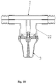
- alternative accessories are connected to the adapter (2), e.g. a filter (301) as shown in Fig. 19 ; a humidifier (302) as shown in Fig. 20 ; and an automatic drug dispenser (303) as shown in Fig. 21 .
Abstract
Description
- The invention relates generally to medical equipment, and more particularly to a bi-lumen (double-lumen) breathing circuit assembly comprising breathing circuit conduit lengths and a connector.
- At present, only ordinary single-lumen corrugated or flexible connector circuits are compatible with breathing circuit accessories such as water collection cups for collecting exhaled breath condensate. However, the semi-circular or other irregular cross-sectional tube shapes of bi-lumen anaesthesia breathing tubes are typically incompatible with the standard circular cross-section connectors such as those provided on water collection cups. In practice, bi-lumen breathing circuits can make the patient more comfortable by adding moisture into the injected oxygen or anaesthetic gas. However, condensate retained within the circuit for a long time is prone to result in the breeding of bacteria, harming patients and increasing risk of occurrence of ventilator-associated pneumonia. Since bi-lumen breathing tubes are provided in standard lengths, there can be clinical situations where it is necessary to extend the overall length of the tubes. Accordingly, there is a need for an improved bi-lumen breathing circuit assembly which overcomes, or at least ameliorates the aforementioned problems whilst enhancing patient health and wellbeing and improving convenience and flexibility in a wide range of clinical scenarios.
- According to a first aspect of the present invention, there is provided a bi-lumen breathing circuit assembly including first and second breathing circuit conduit lengths each comprising: (i) a lengthwise extending inner septum for segregating inspiratory and expiratory lumens; and (ii) lumen opening pairs at their respective opposite distal ends;
the assembly further comprising a connector comprising: (iii) a lengthwise extending connecting septum for segregating inspiratory and expiratory connector passages; and (iv) a pair of connector openings at their respective opposite distal ends; wherein a concavity is provided at each distal end of the connecting septum for sealingly receiving an inner septum of each breathing circuit conduit length thus ensuring a contiguous passage between connected lengths of breathing circuit conduits. - It will be appreciated that in its simplest form, the invention provides a quick and simple means of connecting together two bi-lumen breathing circuit conduit lengths in order to extend their overall length in accordance with clinical needs.
- Optionally, an interference fit is defined between the respective septa.
- Optionally, each inner septum is engageable within its corresponding concavity in a push-fit manner.
- It will be appreciated that an interference push fit requires the depth dimension of the septa to be equal to, or slightly more than, the corresponding depth dimension of the concavity.
- In an alternative embodiment, one of the connector passages within the connector is divided into separate inflow and outflow passages; wherein an intermediate inflow opening is provided in the inflow passage, and an intermediate outflow opening is provided in the outflow passage.
- It will be appreciated that the connector arrangement defined above can adopt various different shapes. By way of non-limiting example, the overall shape of the connector may be a "TT" shape, or the shape of the mathematical "Pi" symbol. The inflow and outflow passages which define the upper parts of the "TT" or "Pi" shapes may adopt an inclined "V" shape. This shape minimises flow resistance and provides a natural guidance into, for example, a water collection cup.
- In a further alternative embodiment, the inspiratory and the expiratory connector passages within the connector are each divided so as to comprise separate inflow and outflow passages; and wherein an intermediate inflow opening is provided in each inflow passage, and an intermediate outflow opening is provided in each outflow passage.
- It will be appreciated that the connector arrangement defined above can adopt various different shapes. By way of non-limiting example, the overall shape of the connector may be similar mathematical "+" symbol. In this arrangement, an accessory such as a condensate collector may be fitted to the intermediate openings at both the inspiratory and the expiratory connector passages.
Optionally, the - or each - connector passage within the connector is divided into separate inflow and outflow passages by at least one contiguous extension of its connecting septum. - Optionally, an accessory is fitted between the inflow and outflow passages.
- Optionally, the accessory is selected from the group comprising: a condensate collector, a filter, a humidifier or an automatic doser.
- Optionally, distal end walls proximate the connector openings are sealingly connectable with a lumen opening pair of a breathing circuit conduit length.
- Optionally, internal surface portions on each conduit length proximate each lumen opening pair are provided with a textured, ribbed or grooved surface profile.
- It will be appreciated that such an internal surface profile enhances grip between the respective connector and conduit walls proximate the respective lumen and connector openings. The overall connection between the connector and each conduit length is enhanced further by providing the latter with a tapered external surface which diminishes towards each distal end. In this way, the two halves of each connector above and below each concavity hinge and are compressible towards one another when the connector engages with a conduit length. A reliable connection may additionally, or alternatively, be achieved by one or more of a clamp, sealing ring, collet, buckle or an adhesive.
- Optionally, one bi-lumen breathing circuit conduit length is connectable to apparatus at a patient side, and the other bi-lumen breathing circuit conduit length is indirectly or directly connectable to an anaesthetic gas outlet, and to a carbon dioxide sampling connector.
- Embodiments of the present invention will now be described, by way of example only, with reference to the accompanying drawings in which:
-
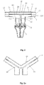
Fig. 1 is a side view of a bi-lumen breathing circuit assembly of the present invention connected to a water collection cup (condensate collector); -
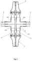
Fig. 2 illustrates a partial cross-sectional view of the bi-lumen breathing circuit assembly ofFig. 1 ; andFig. 2a illustrates a cross-sectional view of a "Y" shaped adapter; -
Fig. 3 is a side view of a bi-lumen breathing circuit assembly connected to two water collection cups; -
Fig. 4 illustrates a partial cross-sectional view of the bi-lumen breathing circuit assembly ofFig. 3 ; -
Fig. 5 is a side view of a bi-lumen breathing circuit assembly connected to a group of extension tubes and one water collection cup; -
Fig. 6 illustrates a partial cross-sectional view of the bi-lumen breathing circuit assembly ofFig. 5 ; -
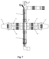
Fig. 7 is a side view of a bi-lumen breathing circuit assembly connected to two groups of extension tubes and two water collection cups; -
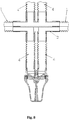
Fig. 8 illustrates a partial cross-sectional view of the bi-lumen breathing circuit assembly ofFig. 7 ; -
Fig. 9 is a side view of a bi-lumen breathing circuit assembly with an integrally formed accessory; -
Fig. 10 illustrates a partial cross-sectional view of the bi-lumen breathing circuit assembly ofFig. 9 ; -
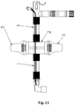
Fig. 11 is a side view of a bi-lumen breathing circuit assembly comprising two integrally formed accessories; -
Fig. 12 illustrates a partial cross-sectional view of the bi-lumen breathing circuit assembly ofFig. 11 ; -
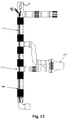
Fig. 13 is a side view of a bi-lumen breathing circuit assembly adopting an alternative configuration; -
Fig. 14 illustrates a partial cross-sectional view of one part of the bilumen breathing circuit assembly ofFig. 13 ; -
Fig. 15 illustrates a partial cross-sectional view of another part of the bilumen breathing circuit assembly ofFig. 13 ; -
Fig. 16 is a side view of a bi-lumen breathing circuit assembly adopting a further alternative configuration; -
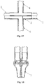
Fig. 17 illustrates a partial cross-sectional view of one part of the bi-lumen breathing circuit assembly ofFig. 16 ; -
Fig. 18 illustrates a partial cross-sectional view of another part of the bi-lumen breathing circuit assembly ofFig. 16 ; -
Fig. 19 is a side view of a bi-lumen breathing circuit assembly connected to a filter; -
Fig. 20 is a side view of a bilumen breathing circuit assembly connected to a humidifier; -
Fig. 21 is a side view of a bilumen breathing circuit assembly connected to an automatic doser (drug dispenser). - As shown in the figures, the present invention provides a bi-lumen breathing circuit assembly in which separate breathing circuit conduit lengths (1, 11) can be joined together by differently arranged connectors or adapters (2), each having different shapes and associated accessories (3, 301, 302, 303) serving different functions. In each case, the breathing circuit conduit lengths (1, 11) are provided with an inner septum (12) extending both diametrically and axially therein for segregating inspiratory and expiratory lumens (110). Each septum (12) terminates at the opposite distal ends (21) of the conduit lengths and forms a pair of semi-circular lumen openings. As shown in
Fig. 1 , one of the bi-lumen breathing circuits (1) is connected to patient-side connector (5), and the otherbi-lumen breathing circuit 1 is connected to, or integrally moulded with, a gas collection plug (6) of an anaesthetic gas machine. The latter bi-lumen breathing circuit (1) is further connected to, or integrally moulded with, a carbon dioxide sampling connector (7) and a temperature probe and/or pressure sensor probe (8). - As shown in
Fig. 2 , the connector or adapter (2) adopts a "TT" or "Pi" shape. A lengthwise extending connector septum (24) segregates inspiratory and expiratory connector passages (50, 60) each of which terminate in connector openings at their respective opposite distal ends. An internal lengthwise concavity (70) in the form a slit is formed at each of the respective opposite distal ends of the connector septum (24). Each slit or concavity (70) is shaped and dimensioned to receive an inner septum (12) associated with a breathing circuit conduit length (1, 11) in a sealing fashion thus ensuring good air-tightness and reliability. - The inner septum (12) and the slit or concavity (70) are shaped and dimensioned so as to provide an interference fit. Therefore, when a breathing circuit conduit length (1, 11) is correctly orientated and pushed onto the connector or adapter (2) its inner septum (12) is forced into the slit or concavity (70) in a sealing manner and contiguous separated passages are provided between connected lengths of breathing circuit conduits (1, 11) through the connector or adapter (2). Each conduit length (1, 11) and its associated inner septum (12) is formed by from an extruded plastics material and internal distal end surface portions thereof are provided with a textured, ribbed or grooved surface profile so as to enhance their grip on the external distal end surfaces of the connector or adapter (2) (also formed from a plastics material). The external distal end surfaces may be tapered in a manner in which their diameter reduces slightly towards their opposite distal ends. The tapered external end surfaces on the connector or adapter (2) enable the semi-circular lumen openings to be press-fitted thereon to effect a progressively tighter and more reliable seal between the connector or adapter (2) and the breathing circuit conduits (1, 11). Alternatively, or additionally, a fastener (e.g. a sealing ring (10)) or an adhesive may be employed to effect a reliable seal.
- Referring again to
Fig. 2 , the lower of the two connector passages (60) is divided into separate inflow and outflow passages (220), each of which are connected to a water collection cup (3) for collecting condensate. Condensate flows into thewater collection cup 3 due to gravity. Removal of the condensate promotes patient health by preventing bacteria from breeding in the condensed water, thus reducing the occurrence of ventilator-associated pneumonia. - By way of example only, the lower left passage in
Fig. 2 may be considered as the inflow passage (220) and the lower right passage may be considered as the outflow passage (220). An intermediate inflow opening (220) is provided in the inflow passage and connects the inflow passage to the water collection cup (3). Similarly, an intermediate outflow opening (220) connects the water collection cup (3) to the outflow passage at its distal end (22). Each connection may be effected in a similar press-fit manner to that described above in relation to the connection between the connector or adapter (2) and the breathing circuit conduits (1, 11). This ensures good air tightness and reliability. - Referring now to the embodiment of
Figs. 3 and4 , the connector or adapter (2) adopts a cross or "#" shape. The structure of the adapter is essentially the same as that described above in association with the embodiment ofFigs 1 and2 . However, in this embodiment both the upper and the lower connector passages (60, 70) is divided into separate inflow and outflow passages, each of which are connected to a separate water collection cups (3) via intermediate inflow and outflow openings (220). - In the specific example illustrated in
Fig. 2 , intubation tubes (31) are inserted into to each of the intermediate inflow and outflow openings (220) in a push-fit manner. The distal ends of the intermediate inflow and outflow openings (220) may be provided with conical internal surface profiles to facilitate the connection. The opposite ends of the intubation tubes are inserted into the water collection cup (3). In the alternative embodiments ofFigs. 5 ,6 and7 ,8 extensions in the form of corrugated or flexible tubing connect the adapter (2) to the water collection cup (3). - In the alternative embodiments of
Figs. 9 ,10 and11 ,12 , the water collection cups (3) are provided as an integral part of the adapter (2) rather than as a separate connectable part. - In the further alternative embodiments of
Figs. 13 ,14 ,15 and16 ,17, 18 , more complex combinations of adapters (2) and water collection cup (3) are illustrated which provide flexibility for a range of clinical scenarios. - In further alternative embodiments alternative accessories are connected to the adapter (2), e.g. a filter (301) as shown in
Fig. 19 ; a humidifier (302) as shown inFig. 20 ; and an automatic drug dispenser (303) as shown inFig. 21 . - Although particular embodiments of the invention have been disclosed herein in detail, this has been done by way of example and for the purposes of illustration only. The aforementioned embodiments are not intended to be limiting with respect to the scope of the appended claims. Indeed, it is contemplated by the inventor that various substitutions, alterations, and modifications may be made to the invention without departing from the scope of the invention as defined by the accompanying claims.
Claims (12)
- A bi-lumen breathing circuit assembly including first and second breathing circuit conduit lengths each comprising:(i) a lengthwise extending inner septum for segregating inspiratory and expiratory lumens; and(ii) lumen opening pairs at their respective opposite distal ends;the assembly further comprising a connector comprising:(iii) a lengthwise extending connector septum for segregating inspiratory and expiratory connector passages; and(iv) a pair of connector openings at its respective opposite distal ends;wherein a concavity is provided at each distal end of the connecting septum for sealingly receiving an inner septum of each breathing circuit conduit length thus ensuring a contiguous passage between connected lengths of breathing circuit conduits.
- A bi-lumen breathing circuit assembly according to claim 1, wherein an interference fit is defined between the respective septa.
- A bi-lumen breathing circuit assembly according to any of claims 1 or 2, wherein each inner septum is engageable within its corresponding concavity in a push-fit manner.
- A bi-lumen breathing circuit assembly according to any preceding claim, wherein internal surface portions on each conduit length are provided with a textured, ribbed or grooved surface profile.
- A bi-lumen breathing circuit assembly according to any preceding claim, wherein one of the connector passages within the connector is divided into separate inflow and outflow passages; wherein an intermediate inflow opening is provided in the inflow passage, and an intermediate outflow opening is provided in the outflow passage.
- A bi-lumen breathing circuit assembly according to claim 5, wherein both the inspiratory and the expiratory connector passages within the connector are each divided so as to comprise separate inflow and outflow passages; and wherein an intermediate inflow opening is provided in each inflow passage, and an intermediate outflow opening is
- A bi-lumen breathing circuit assembly according to claim 5 or 6, wherein the - or each - connector passage within the connector is divided into separate inflow and outflow passages by at least one contiguous extension of its connecting septum.
- A bi-lumen breathing circuit assembly according to any of claims 5 to 7, wherein an accessory is fitted between the inflow and outflow passages.
- A bi-lumen breathing circuit assembly according to claim 8, wherein the accessory is selected from the group comprising: a condensate collector, a filter, a humidifier or an automatic doser.
- A bi-lumen breathing circuit assembly according to any preceding claim, wherein distal end walls proximate the connector openings are sealingly connectable with a lumen opening pair of a breathing circuit conduit length.
- A bi-lumen breathing circuit assembly according to any preceding claim, wherein internal surface portions on each conduit length proximate each lumen opening pair are provided with a textured, ribbed or grooved surface profile.
- A bi-lumen breathing circuit assembly according to any preceding claim, wherein one bi-lumen breathing circuit conduit length is connectable to apparatus at a patient side, and the other bi-lumen breathing circuit conduit length is indirectly or directly connectable to an anaesthetic gas outlet and to a carbon dioxide sampling connector.
Applications Claiming Priority (2)
| Application Number | Priority Date | Filing Date | Title |
|---|---|---|---|
| CN201590000021.1U CN204798549U (en) | 2015-05-08 | 2015-05-08 | Well minute pipe assembly that contains multi -functional adapter |
| PCT/CN2015/078560 WO2016179746A1 (en) | 2015-05-08 | 2015-05-08 | Middle division pipe assembly including multifunctional adapter |
Publications (2)
| Publication Number | Publication Date |
|---|---|
| EP3090774A1 true EP3090774A1 (en) | 2016-11-09 |
| EP3090774B1 EP3090774B1 (en) | 2017-08-30 |
Family
ID=55919699
Family Applications (1)
| Application Number | Title | Priority Date | Filing Date |
|---|---|---|---|
| EP16168562.3A Active EP3090774B1 (en) | 2015-05-08 | 2016-05-06 | Bi-lumen breathing circuit assembly |
Country Status (3)
| Country | Link |
|---|---|
| US (1) | US20160325070A1 (en) |
| EP (1) | EP3090774B1 (en) |
| CN (1) | CN204798549U (en) |
Cited By (2)
| Publication number | Priority date | Publication date | Assignee | Title |
|---|---|---|---|---|
| WO2021018902A1 (en) | 2019-08-01 | 2021-02-04 | Hamilton Medical Ag | Respiratory gas valve assembly through which respiratory gas can flow in a bidirectional manner, and ventilation device comprising such a valve assembly |
| US11565070B2 (en) * | 2018-01-15 | 2023-01-31 | Meditera Tibbi Malzeme Sanayi Ve Tioaret A.S. | Coaxial breathing circuit systems having a lung pressure measurement port and closed system water trap which can be drained with an enjector |
Families Citing this family (10)
| Publication number | Priority date | Publication date | Assignee | Title |
|---|---|---|---|---|
| US20150342259A1 (en) * | 2014-05-30 | 2015-12-03 | Carolina Vapordom, LLC | E-liquid vaporizing apparatus |
| CA2984104A1 (en) | 2015-04-27 | 2016-11-03 | Teleflex Medical Incorporated | Humidification device |
| US10857321B2 (en) | 2015-10-24 | 2020-12-08 | Ambu A/S | Breathing circuit systems and devices |
| CN106390262A (en) * | 2016-10-14 | 2017-02-15 | 柳州环山科技有限公司 | Ultrasonic atomization device of breathing machine |
| EP3532139A4 (en) | 2016-10-26 | 2020-09-23 | Teleflex Medical Incorporated | System and method for on-demand near-patient humidification |
| CN109420229A (en) * | 2017-09-01 | 2019-03-05 | 深圳安维森实业有限公司 | Respiratory siphon group |
| CN108969862A (en) * | 2018-09-28 | 2018-12-11 | 重庆智延科技发展有限公司 | Breathing circuit combines formula captation with spiral cover with arc leak hole |
| CN109621144A (en) * | 2018-09-28 | 2019-04-16 | 重庆智延科技发展有限公司 | Self-cleaning type Anesthesia machine, breathing circuit double containment captation |
| CN110755726A (en) * | 2019-10-21 | 2020-02-07 | 斯莱达医疗用品(惠州)有限公司 | Coaxial heating breathing pipeline |
| CN113304375B (en) * | 2021-05-12 | 2023-06-27 | 湖南万脉医疗科技有限公司 | Novel breathing machine pipeline and breathing machine thereof |
Citations (3)
| Publication number | Priority date | Publication date | Assignee | Title |
|---|---|---|---|---|
| EP0460731A1 (en) * | 1990-06-08 | 1991-12-11 | Intersurgical Limited | Water trap for respiratory airline |
| US20140150794A1 (en) * | 2012-12-03 | 2014-06-05 | Carefusion Corporation | Fluid trap apparatus |
| US20140276178A1 (en) * | 2013-03-13 | 2014-09-18 | David Lew Simon | Multi-lumen breathing tube device |
Family Cites Families (7)
| Publication number | Priority date | Publication date | Assignee | Title |
|---|---|---|---|---|
| US4829998A (en) * | 1988-02-25 | 1989-05-16 | Jackson Richard R | Delivering breathable gas |
| US6508249B2 (en) * | 2000-10-05 | 2003-01-21 | Vital Signs, Inc. | Connecting apparatus for placing fluid flow paths in fluid communication |
| NZ532166A (en) * | 2001-09-24 | 2007-01-26 | Atsuo F Fukunaga | Breathing circuits having unconventional respiratory conduits and systems and methods for optimising utilisation of fresh gases |
| US8252081B2 (en) * | 2007-07-17 | 2012-08-28 | Teleflex Medical Incorporated | Water dissipation device and method |
| GB0806648D0 (en) * | 2008-04-11 | 2008-05-14 | Univ Manchester | Breathing system |
| US8156935B2 (en) * | 2009-04-06 | 2012-04-17 | Hsiner Co., Ltd. | Respiratory tube assembly |
| US20120266888A1 (en) * | 2011-04-21 | 2012-10-25 | Teleflex Medical Incorporated | Automatic water removal device and method |
-
2015
- 2015-05-08 CN CN201590000021.1U patent/CN204798549U/en active Active
-
2016
- 2016-05-06 US US15/148,021 patent/US20160325070A1/en not_active Abandoned
- 2016-05-06 EP EP16168562.3A patent/EP3090774B1/en active Active
Patent Citations (3)
| Publication number | Priority date | Publication date | Assignee | Title |
|---|---|---|---|---|
| EP0460731A1 (en) * | 1990-06-08 | 1991-12-11 | Intersurgical Limited | Water trap for respiratory airline |
| US20140150794A1 (en) * | 2012-12-03 | 2014-06-05 | Carefusion Corporation | Fluid trap apparatus |
| US20140276178A1 (en) * | 2013-03-13 | 2014-09-18 | David Lew Simon | Multi-lumen breathing tube device |
Cited By (2)
| Publication number | Priority date | Publication date | Assignee | Title |
|---|---|---|---|---|
| US11565070B2 (en) * | 2018-01-15 | 2023-01-31 | Meditera Tibbi Malzeme Sanayi Ve Tioaret A.S. | Coaxial breathing circuit systems having a lung pressure measurement port and closed system water trap which can be drained with an enjector |
| WO2021018902A1 (en) | 2019-08-01 | 2021-02-04 | Hamilton Medical Ag | Respiratory gas valve assembly through which respiratory gas can flow in a bidirectional manner, and ventilation device comprising such a valve assembly |
Also Published As
| Publication number | Publication date |
|---|---|
| US20160325070A1 (en) | 2016-11-10 |
| EP3090774B1 (en) | 2017-08-30 |
| CN204798549U (en) | 2015-11-25 |
Similar Documents
| Publication | Publication Date | Title |
|---|---|---|
| EP3090774B1 (en) | Bi-lumen breathing circuit assembly | |
| AU2022203726B2 (en) | Conduit connector for a patient breathing device | |
| US4828550A (en) | Enteral feeding and suction tube assembly | |
| US20040171997A1 (en) | Double-y-shaped multi-lumen catheter with selectively attachable hubs | |
| EP1845841B1 (en) | Capnographic sampling catheter | |
| US20090192448A1 (en) | Oral gastric lavage apparatus | |
| US11351325B2 (en) | Dual-connector wye piece | |
| US10695518B2 (en) | Oral cannula | |
| US9919122B2 (en) | Fluid trap apparatus | |
| US20160228035A1 (en) | Naso-oral device | |
| US20210060275A1 (en) | Airway device | |
| CN204910380U (en) | Laryngeal mask with open recess | |
| TWI833442B (en) | Conduit connector for a patient breathing device |
Legal Events
| Date | Code | Title | Description |
|---|---|---|---|
| PUAI | Public reference made under article 153(3) epc to a published international application that has entered the european phase |
Free format text: ORIGINAL CODE: 0009012 |
|
| AK | Designated contracting states |
Kind code of ref document: A1 Designated state(s): AL AT BE BG CH CY CZ DE DK EE ES FI FR GB GR HR HU IE IS IT LI LT LU LV MC MK MT NL NO PL PT RO RS SE SI SK SM TR |
|
| AX | Request for extension of the european patent |
Extension state: BA ME |
|
| 17P | Request for examination filed |
Effective date: 20170327 |
|
| RBV | Designated contracting states (corrected) |
Designated state(s): AL AT BE BG CH CY CZ DE DK EE ES FI FR GB GR HR HU IE IS IT LI LT LU LV MC MK MT NL NO PL PT RO RS SE SI SK SM TR |
|
| GRAJ | Information related to disapproval of communication of intention to grant by the applicant or resumption of examination proceedings by the epo deleted |
Free format text: ORIGINAL CODE: EPIDOSDIGR1 |
|
| GRAP | Despatch of communication of intention to grant a patent |
Free format text: ORIGINAL CODE: EPIDOSNIGR1 |
|
| INTG | Intention to grant announced |
Effective date: 20170613 |
|
| GRAS | Grant fee paid |
Free format text: ORIGINAL CODE: EPIDOSNIGR3 |
|
| GRAA | (expected) grant |
Free format text: ORIGINAL CODE: 0009210 |
|
| AK | Designated contracting states |
Kind code of ref document: B1 Designated state(s): AL AT BE BG CH CY CZ DE DK EE ES FI FR GB GR HR HU IE IS IT LI LT LU LV MC MK MT NL NO PL PT RO RS SE SI SK SM TR |
|
| REG | Reference to a national code |
Ref country code: GB Ref legal event code: FG4D |
|
| REG | Reference to a national code |
Ref country code: CH Ref legal event code: EP |
|
| REG | Reference to a national code |
Ref country code: AT Ref legal event code: REF Ref document number: 922951 Country of ref document: AT Kind code of ref document: T Effective date: 20170915 |
|
| REG | Reference to a national code |
Ref country code: IE Ref legal event code: FG4D |
|
| REG | Reference to a national code |
Ref country code: DE Ref legal event code: R096 Ref document number: 602016000316 Country of ref document: DE |
|
| REG | Reference to a national code |
Ref country code: NL Ref legal event code: MP Effective date: 20170830 |
|
| REG | Reference to a national code |
Ref country code: LT Ref legal event code: MG4D |
|
| REG | Reference to a national code |
Ref country code: AT Ref legal event code: MK05 Ref document number: 922951 Country of ref document: AT Kind code of ref document: T Effective date: 20170830 |
|
| PG25 | Lapsed in a contracting state [announced via postgrant information from national office to epo] |
Ref country code: AT Free format text: LAPSE BECAUSE OF FAILURE TO SUBMIT A TRANSLATION OF THE DESCRIPTION OR TO PAY THE FEE WITHIN THE PRESCRIBED TIME-LIMIT Effective date: 20170830 Ref country code: SE Free format text: LAPSE BECAUSE OF FAILURE TO SUBMIT A TRANSLATION OF THE DESCRIPTION OR TO PAY THE FEE WITHIN THE PRESCRIBED TIME-LIMIT Effective date: 20170830 Ref country code: LT Free format text: LAPSE BECAUSE OF FAILURE TO SUBMIT A TRANSLATION OF THE DESCRIPTION OR TO PAY THE FEE WITHIN THE PRESCRIBED TIME-LIMIT Effective date: 20170830 Ref country code: HR Free format text: LAPSE BECAUSE OF FAILURE TO SUBMIT A TRANSLATION OF THE DESCRIPTION OR TO PAY THE FEE WITHIN THE PRESCRIBED TIME-LIMIT Effective date: 20170830 Ref country code: NO Free format text: LAPSE BECAUSE OF FAILURE TO SUBMIT A TRANSLATION OF THE DESCRIPTION OR TO PAY THE FEE WITHIN THE PRESCRIBED TIME-LIMIT Effective date: 20171130 Ref country code: FI Free format text: LAPSE BECAUSE OF FAILURE TO SUBMIT A TRANSLATION OF THE DESCRIPTION OR TO PAY THE FEE WITHIN THE PRESCRIBED TIME-LIMIT Effective date: 20170830 |
|
| PG25 | Lapsed in a contracting state [announced via postgrant information from national office to epo] |
Ref country code: BG Free format text: LAPSE BECAUSE OF FAILURE TO SUBMIT A TRANSLATION OF THE DESCRIPTION OR TO PAY THE FEE WITHIN THE PRESCRIBED TIME-LIMIT Effective date: 20171130 Ref country code: LV Free format text: LAPSE BECAUSE OF FAILURE TO SUBMIT A TRANSLATION OF THE DESCRIPTION OR TO PAY THE FEE WITHIN THE PRESCRIBED TIME-LIMIT Effective date: 20170830 Ref country code: RS Free format text: LAPSE BECAUSE OF FAILURE TO SUBMIT A TRANSLATION OF THE DESCRIPTION OR TO PAY THE FEE WITHIN THE PRESCRIBED TIME-LIMIT Effective date: 20170830 Ref country code: IS Free format text: LAPSE BECAUSE OF FAILURE TO SUBMIT A TRANSLATION OF THE DESCRIPTION OR TO PAY THE FEE WITHIN THE PRESCRIBED TIME-LIMIT Effective date: 20171230 Ref country code: GR Free format text: LAPSE BECAUSE OF FAILURE TO SUBMIT A TRANSLATION OF THE DESCRIPTION OR TO PAY THE FEE WITHIN THE PRESCRIBED TIME-LIMIT Effective date: 20171201 Ref country code: ES Free format text: LAPSE BECAUSE OF FAILURE TO SUBMIT A TRANSLATION OF THE DESCRIPTION OR TO PAY THE FEE WITHIN THE PRESCRIBED TIME-LIMIT Effective date: 20170830 |
|
| PG25 | Lapsed in a contracting state [announced via postgrant information from national office to epo] |
Ref country code: NL Free format text: LAPSE BECAUSE OF FAILURE TO SUBMIT A TRANSLATION OF THE DESCRIPTION OR TO PAY THE FEE WITHIN THE PRESCRIBED TIME-LIMIT Effective date: 20170830 |
|
| PG25 | Lapsed in a contracting state [announced via postgrant information from national office to epo] |
Ref country code: PL Free format text: LAPSE BECAUSE OF FAILURE TO SUBMIT A TRANSLATION OF THE DESCRIPTION OR TO PAY THE FEE WITHIN THE PRESCRIBED TIME-LIMIT Effective date: 20170830 Ref country code: DK Free format text: LAPSE BECAUSE OF FAILURE TO SUBMIT A TRANSLATION OF THE DESCRIPTION OR TO PAY THE FEE WITHIN THE PRESCRIBED TIME-LIMIT Effective date: 20170830 Ref country code: CZ Free format text: LAPSE BECAUSE OF FAILURE TO SUBMIT A TRANSLATION OF THE DESCRIPTION OR TO PAY THE FEE WITHIN THE PRESCRIBED TIME-LIMIT Effective date: 20170830 |
|
| REG | Reference to a national code |
Ref country code: FR Ref legal event code: PLFP Year of fee payment: 3 |
|
| PG25 | Lapsed in a contracting state [announced via postgrant information from national office to epo] |
Ref country code: SK Free format text: LAPSE BECAUSE OF FAILURE TO SUBMIT A TRANSLATION OF THE DESCRIPTION OR TO PAY THE FEE WITHIN THE PRESCRIBED TIME-LIMIT Effective date: 20170830 Ref country code: SM Free format text: LAPSE BECAUSE OF FAILURE TO SUBMIT A TRANSLATION OF THE DESCRIPTION OR TO PAY THE FEE WITHIN THE PRESCRIBED TIME-LIMIT Effective date: 20170830 Ref country code: EE Free format text: LAPSE BECAUSE OF FAILURE TO SUBMIT A TRANSLATION OF THE DESCRIPTION OR TO PAY THE FEE WITHIN THE PRESCRIBED TIME-LIMIT Effective date: 20170830 Ref country code: IT Free format text: LAPSE BECAUSE OF FAILURE TO SUBMIT A TRANSLATION OF THE DESCRIPTION OR TO PAY THE FEE WITHIN THE PRESCRIBED TIME-LIMIT Effective date: 20170830 |
|
| REG | Reference to a national code |
Ref country code: DE Ref legal event code: R097 Ref document number: 602016000316 Country of ref document: DE |
|
| PLBE | No opposition filed within time limit |
Free format text: ORIGINAL CODE: 0009261 |
|
| STAA | Information on the status of an ep patent application or granted ep patent |
Free format text: STATUS: NO OPPOSITION FILED WITHIN TIME LIMIT |
|
| 26N | No opposition filed |
Effective date: 20180531 |
|
| PG25 | Lapsed in a contracting state [announced via postgrant information from national office to epo] |
Ref country code: SI Free format text: LAPSE BECAUSE OF FAILURE TO SUBMIT A TRANSLATION OF THE DESCRIPTION OR TO PAY THE FEE WITHIN THE PRESCRIBED TIME-LIMIT Effective date: 20170830 |
|
| REG | Reference to a national code |
Ref country code: BE Ref legal event code: MM Effective date: 20180531 |
|
| PG25 | Lapsed in a contracting state [announced via postgrant information from national office to epo] |
Ref country code: MC Free format text: LAPSE BECAUSE OF FAILURE TO SUBMIT A TRANSLATION OF THE DESCRIPTION OR TO PAY THE FEE WITHIN THE PRESCRIBED TIME-LIMIT Effective date: 20170830 |
|
| REG | Reference to a national code |
Ref country code: IE Ref legal event code: MM4A |
|
| PG25 | Lapsed in a contracting state [announced via postgrant information from national office to epo] |
Ref country code: LU Free format text: LAPSE BECAUSE OF NON-PAYMENT OF DUE FEES Effective date: 20180506 |
|
| PG25 | Lapsed in a contracting state [announced via postgrant information from national office to epo] |
Ref country code: IE Free format text: LAPSE BECAUSE OF NON-PAYMENT OF DUE FEES Effective date: 20180506 |
|
| PG25 | Lapsed in a contracting state [announced via postgrant information from national office to epo] |
Ref country code: BE Free format text: LAPSE BECAUSE OF NON-PAYMENT OF DUE FEES Effective date: 20180531 |
|
| REG | Reference to a national code |
Ref country code: CH Ref legal event code: PL |
|
| PG25 | Lapsed in a contracting state [announced via postgrant information from national office to epo] |
Ref country code: LI Free format text: LAPSE BECAUSE OF NON-PAYMENT OF DUE FEES Effective date: 20190531 Ref country code: MT Free format text: LAPSE BECAUSE OF NON-PAYMENT OF DUE FEES Effective date: 20180506 Ref country code: CH Free format text: LAPSE BECAUSE OF NON-PAYMENT OF DUE FEES Effective date: 20190531 |
|
| PG25 | Lapsed in a contracting state [announced via postgrant information from national office to epo] |
Ref country code: TR Free format text: LAPSE BECAUSE OF FAILURE TO SUBMIT A TRANSLATION OF THE DESCRIPTION OR TO PAY THE FEE WITHIN THE PRESCRIBED TIME-LIMIT Effective date: 20170830 |
|
| PG25 | Lapsed in a contracting state [announced via postgrant information from national office to epo] |
Ref country code: PT Free format text: LAPSE BECAUSE OF FAILURE TO SUBMIT A TRANSLATION OF THE DESCRIPTION OR TO PAY THE FEE WITHIN THE PRESCRIBED TIME-LIMIT Effective date: 20170830 |
|
| PG25 | Lapsed in a contracting state [announced via postgrant information from national office to epo] |
Ref country code: RO Free format text: LAPSE BECAUSE OF FAILURE TO SUBMIT A TRANSLATION OF THE DESCRIPTION OR TO PAY THE FEE WITHIN THE PRESCRIBED TIME-LIMIT Effective date: 20170830 Ref country code: HU Free format text: LAPSE BECAUSE OF FAILURE TO SUBMIT A TRANSLATION OF THE DESCRIPTION OR TO PAY THE FEE WITHIN THE PRESCRIBED TIME-LIMIT; INVALID AB INITIO Effective date: 20160506 Ref country code: CY Free format text: LAPSE BECAUSE OF FAILURE TO SUBMIT A TRANSLATION OF THE DESCRIPTION OR TO PAY THE FEE WITHIN THE PRESCRIBED TIME-LIMIT Effective date: 20170830 Ref country code: MK Free format text: LAPSE BECAUSE OF NON-PAYMENT OF DUE FEES Effective date: 20170830 |
|
| PG25 | Lapsed in a contracting state [announced via postgrant information from national office to epo] |
Ref country code: AL Free format text: LAPSE BECAUSE OF FAILURE TO SUBMIT A TRANSLATION OF THE DESCRIPTION OR TO PAY THE FEE WITHIN THE PRESCRIBED TIME-LIMIT Effective date: 20170830 |
|
| PGFP | Annual fee paid to national office [announced via postgrant information from national office to epo] |
Ref country code: GB Payment date: 20230314 Year of fee payment: 8 |
|
| PGFP | Annual fee paid to national office [announced via postgrant information from national office to epo] |
Ref country code: FR Payment date: 20230508 Year of fee payment: 8 Ref country code: DE Payment date: 20230508 Year of fee payment: 8 |
|
| P01 | Opt-out of the competence of the unified patent court (upc) registered |
Effective date: 20240305 |