EP3090692A1 - Implant conveying device and implanted medical instrument - Google Patents
Implant conveying device and implanted medical instrument Download PDFInfo
- Publication number
- EP3090692A1 EP3090692A1 EP14875946.7A EP14875946A EP3090692A1 EP 3090692 A1 EP3090692 A1 EP 3090692A1 EP 14875946 A EP14875946 A EP 14875946A EP 3090692 A1 EP3090692 A1 EP 3090692A1
- Authority
- EP
- European Patent Office
- Prior art keywords
- implant
- wire
- lock
- control
- connecting wire
- Prior art date
- Legal status (The legal status is an assumption and is not a legal conclusion. Google has not performed a legal analysis and makes no representation as to the accuracy of the status listed.)
- Granted
Links
Images


Classifications
-
- A—HUMAN NECESSITIES
- A61—MEDICAL OR VETERINARY SCIENCE; HYGIENE
- A61B—DIAGNOSIS; SURGERY; IDENTIFICATION
- A61B17/00—Surgical instruments, devices or methods
- A61B17/0057—Implements for plugging an opening in the wall of a hollow or tubular organ, e.g. for sealing a vessel puncture or closing a cardiac septal defect
-
- A—HUMAN NECESSITIES
- A61—MEDICAL OR VETERINARY SCIENCE; HYGIENE
- A61B—DIAGNOSIS; SURGERY; IDENTIFICATION
- A61B17/00—Surgical instruments, devices or methods
- A61B17/12—Surgical instruments, devices or methods for ligaturing or otherwise compressing tubular parts of the body, e.g. blood vessels or umbilical cord
- A61B17/12022—Occluding by internal devices, e.g. balloons or releasable wires
- A61B17/12099—Occluding by internal devices, e.g. balloons or releasable wires characterised by the location of the occluder
- A61B17/12109—Occluding by internal devices, e.g. balloons or releasable wires characterised by the location of the occluder in a blood vessel
-
- A—HUMAN NECESSITIES
- A61—MEDICAL OR VETERINARY SCIENCE; HYGIENE
- A61B—DIAGNOSIS; SURGERY; IDENTIFICATION
- A61B17/00—Surgical instruments, devices or methods
- A61B17/12—Surgical instruments, devices or methods for ligaturing or otherwise compressing tubular parts of the body, e.g. blood vessels or umbilical cord
- A61B17/12022—Occluding by internal devices, e.g. balloons or releasable wires
- A61B17/12099—Occluding by internal devices, e.g. balloons or releasable wires characterised by the location of the occluder
- A61B17/12122—Occluding by internal devices, e.g. balloons or releasable wires characterised by the location of the occluder within the heart
-
- A—HUMAN NECESSITIES
- A61—MEDICAL OR VETERINARY SCIENCE; HYGIENE
- A61B—DIAGNOSIS; SURGERY; IDENTIFICATION
- A61B17/00—Surgical instruments, devices or methods
- A61B17/12—Surgical instruments, devices or methods for ligaturing or otherwise compressing tubular parts of the body, e.g. blood vessels or umbilical cord
- A61B17/12022—Occluding by internal devices, e.g. balloons or releasable wires
- A61B17/12131—Occluding by internal devices, e.g. balloons or releasable wires characterised by the type of occluding device
- A61B17/1214—Coils or wires
- A61B17/12145—Coils or wires having a pre-set deployed three-dimensional shape
-
- A—HUMAN NECESSITIES
- A61—MEDICAL OR VETERINARY SCIENCE; HYGIENE
- A61B—DIAGNOSIS; SURGERY; IDENTIFICATION
- A61B17/00—Surgical instruments, devices or methods
- A61B17/0057—Implements for plugging an opening in the wall of a hollow or tubular organ, e.g. for sealing a vessel puncture or closing a cardiac septal defect
- A61B2017/00575—Implements for plugging an opening in the wall of a hollow or tubular organ, e.g. for sealing a vessel puncture or closing a cardiac septal defect for closure at remote site, e.g. closing atrial septum defects
- A61B2017/00623—Introducing or retrieving devices therefor
-
- A—HUMAN NECESSITIES
- A61—MEDICAL OR VETERINARY SCIENCE; HYGIENE
- A61B—DIAGNOSIS; SURGERY; IDENTIFICATION
- A61B17/00—Surgical instruments, devices or methods
- A61B17/12—Surgical instruments, devices or methods for ligaturing or otherwise compressing tubular parts of the body, e.g. blood vessels or umbilical cord
- A61B17/12022—Occluding by internal devices, e.g. balloons or releasable wires
- A61B2017/1205—Introduction devices
-
- A—HUMAN NECESSITIES
- A61—MEDICAL OR VETERINARY SCIENCE; HYGIENE
- A61B—DIAGNOSIS; SURGERY; IDENTIFICATION
- A61B17/00—Surgical instruments, devices or methods
- A61B17/12—Surgical instruments, devices or methods for ligaturing or otherwise compressing tubular parts of the body, e.g. blood vessels or umbilical cord
- A61B17/12022—Occluding by internal devices, e.g. balloons or releasable wires
- A61B2017/1205—Introduction devices
- A61B2017/12054—Details concerning the detachment of the occluding device from the introduction device
-
- A—HUMAN NECESSITIES
- A61—MEDICAL OR VETERINARY SCIENCE; HYGIENE
- A61F—FILTERS IMPLANTABLE INTO BLOOD VESSELS; PROSTHESES; DEVICES PROVIDING PATENCY TO, OR PREVENTING COLLAPSING OF, TUBULAR STRUCTURES OF THE BODY, e.g. STENTS; ORTHOPAEDIC, NURSING OR CONTRACEPTIVE DEVICES; FOMENTATION; TREATMENT OR PROTECTION OF EYES OR EARS; BANDAGES, DRESSINGS OR ABSORBENT PADS; FIRST-AID KITS
- A61F2/00—Filters implantable into blood vessels; Prostheses, i.e. artificial substitutes or replacements for parts of the body; Appliances for connecting them with the body; Devices providing patency to, or preventing collapsing of, tubular structures of the body, e.g. stents
- A61F2/01—Filters implantable into blood vessels
- A61F2/011—Instruments for their placement or removal
-
- A—HUMAN NECESSITIES
- A61—MEDICAL OR VETERINARY SCIENCE; HYGIENE
- A61F—FILTERS IMPLANTABLE INTO BLOOD VESSELS; PROSTHESES; DEVICES PROVIDING PATENCY TO, OR PREVENTING COLLAPSING OF, TUBULAR STRUCTURES OF THE BODY, e.g. STENTS; ORTHOPAEDIC, NURSING OR CONTRACEPTIVE DEVICES; FOMENTATION; TREATMENT OR PROTECTION OF EYES OR EARS; BANDAGES, DRESSINGS OR ABSORBENT PADS; FIRST-AID KITS
- A61F2220/00—Fixations or connections for prostheses classified in groups A61F2/00 - A61F2/26 or A61F2/82 or A61F9/00 or A61F11/00 or subgroups thereof
- A61F2220/0025—Connections or couplings between prosthetic parts, e.g. between modular parts; Connecting elements
- A61F2220/0075—Connections or couplings between prosthetic parts, e.g. between modular parts; Connecting elements sutured, ligatured or stitched, retained or tied with a rope, string, thread, wire or cable
Definitions
- the conveying device of the present invention does not need to be additionally provided with a locking ring on the surface of the implant, so that the amount of metal remaining in the human body is reduced after the implant is implanted into the human body, thereby reducing potential biological risk and avoiding a thrombus source for the implant.
- the length of the connecting wire in the conveying device of the present invention may be freely adjusted during a process of assembling with the lock, so that the difficulty in controlling the length of the locking ring in the production process is reduced, and the production yield in the assembling process is improved.
Landscapes
- Health & Medical Sciences (AREA)
- Life Sciences & Earth Sciences (AREA)
- Surgery (AREA)
- Biomedical Technology (AREA)
- Public Health (AREA)
- Engineering & Computer Science (AREA)
- Heart & Thoracic Surgery (AREA)
- Veterinary Medicine (AREA)
- Animal Behavior & Ethology (AREA)
- General Health & Medical Sciences (AREA)
- Cardiology (AREA)
- Medical Informatics (AREA)
- Nuclear Medicine, Radiotherapy & Molecular Imaging (AREA)
- Molecular Biology (AREA)
- Vascular Medicine (AREA)
- Reproductive Health (AREA)
- Oral & Maxillofacial Surgery (AREA)
- Transplantation (AREA)
- Surgical Instruments (AREA)
- Media Introduction/Drainage Providing Device (AREA)
- Prostheses (AREA)
Abstract
Description
- The present invention relates to medical instruments, in particular to an implant conveying device and an implanted medical instrument including the conveying device.
- Percutaneous interventional technology is a therapeutic method with an increasingly wider application field. A variety of implants, such as a heart defect occluder, a vascular plug, a vascular filter and the like, may be placed into the heart and the artery and vein vessels of the human body by using catheter interventional therapy.
- When these implants are implanted into the heart and the artery and vein vessels of the human body through the catheter interventional method, due to the complex anatomical structures of the heart and the artery and vein vessels of the human body, a catheter, a guide wire and a pusher must be used to ensure that the implant reaches a predetermined position. The catheter first reaches the predetermined position under the guidance of the guide wire. A flexible and fine catheter is required during such an operation, while the catheter and the guide wire are designed to provide good radiopaque characteristics under an X ray. After the catheter reaches the predetermined position, the guide wire is removed, and the implant is then accommodated into the catheter, and guided to the distal end of the catheter by the pusher through a channel established by the catheter. When the implant reaches the distal end of the catheter, the implant is released from the catheter by the pusher, and finally will be disconnected from the pusher, so that the implant is released.
- In prior implantedmedical instruments (hereinafter general terms of implants and pushers), the implants and the pushers are usually in threaded connection or connected by using a connecting wire. For example, a Chinese patent application, of which the application number is
201010265431.2 Fig. 1 , the device includes animplant 1a with aclosure head 2a, and apusher 5a; at least onelock ring 9a is arranged on theimplant 1a, and alock 3a having aninner cavity 8a is arranged on the top end of thepusher 5a. Theinner cavity 8a of thelock 3a is communicated with atube cavity 6a of thepusher 5a; thelock 3a is provided with at least onelock hole 7a, and the tube cavity of thepusher 5a is provided with acontrol wire 4a inside. Thecontrol wire 4a, thelock ring 9a and thelock hole 7a are matched with each other to form a plug structure so as to connect the implant with the pusher, and deliver the implant to a predetermined position, wherein the closure head plays the role of fixing the lock ring which plays the role of connecting, and thecontrol wire 4a is withdrawn to achieve release. - The implanted medical instrument mentioned above has the following disadvantages and limitations. 1. The lock ring is formed at the implant; after the implant is implanted into the human body, the lock ring is also implanted into the human body, resulting in the increase in the amount of metal remaining in the human body. This increase of the amount of metal means the increase of the amount of metal elements released in the human body, resulting in unpredictable biological risk. 2. After the implant is implanted into the human body, it is possible that the lock ring and the surface of the implant are not fitted closely; so that the endothelial tissue subsequently may not completely cover the lock ring, thereby resulting in a thrombus source at the implant.
- A technical problem to be solved by the present invention is to provide an implanted medical instrument capable of reducing biological risk and avoiding the creation of a thrombus source, and to provide an implant conveying device capable of improving surgical success rate.
- A technical solution adopted by the present invention is that an implant conveying device is provided, including a pusher, a control component, a connecting wire and a control wire. The pusher, of which one end is connected to the control component, comprises a tube cavity and a lock hole communicated with the tube cavity; one end of the control wire is connected to the control component, and the other end thereof is capable of being driven by the control component to be movably accommodated in the tube cavity of the pusher. One end of the connecting wire is connected to the pusher or to the control component, and the other end thereof is capable of being used for passing through an implant and then entering the lock hole. The control wire is capable of being driven by the control component to pass through the connecting wire to connect the implant with the conveying device, or the control wire is capable of being driven by the control component to be disengaged from the connecting wire to release the implant.
- Preferably, the length of the connecting wire between the implant and the pusher may be adjustable by the control component, when one end of the connecting wire is fixed in the control component.
- Preferably, the pusher includes a catheter and a lock, one end of the catheter is connected to the control component; the lock with one end being open includes an inner cavity, the open end is communicated with another end of the catheter; the lock hole is defined in the lock and vertically communicated with the tube cavity.
- Preferably, an operating button is arranged on the control component, and one end of the control wire is fixed on the operating button.
- Preferably, a restricting mechanism configured to limit the movement of the operating button is arranged on the control component, the restricting mechanism including a security button, a driving member which is in interaction with the security button and provided with a torsion spring, and an elastic stopper which is capable of being driven by the driving member and configured to restrict the movement of the operating button.
- Preferably, an unopened end surface of the lock is provided with a groove.
- Preferably, a ring is formed on another end of the connecting wire and configured for the control wire to pass therethrough.
- Preferably, the lock is provided with an observation hole configured to confirm whether the unopened end of the lock is propped against the control wire.
- Preferably, one end of the control wire, which is matched with the connecting wire, is bent into a hook-shaped structure; when connecting the implant conveying device with the implant, the hook-shaped structure hooks the connecting wire in a position where the lock hole is located, and pulls the control wire back to a proximal end; the connection is achieved when the hook-shaped structure leaves the inner cavity of the lock; when the implant is disengaged from the connecting wire, the control wire is pushed until the hook-shaped structure passes through a distal end of the lock hole.
- Another technical solution adopted by the present invention is that an implanted medical instrument is provided, including an implant and the implant conveying device mentioned above; the implant has a through hole, another end of the connecting wire passes through the through hole and enters the lock hole, and is sleeved on the control wire; the control wire is capable of being driven by the control component to be disengaged from the connecting wire to release the implant.
- Preferably, the implant has a mesh structure and a closure head configured to restrain the mesh structure, the through hole is a gap formed by mutually enclosing the nickel-titanium alloy wires, or a hole formed on the implant. A manufacturing method of the through hole includes a step of: forming a through hole on the implant; or placing a transverse mold bar into a nickel-titanium wire mesh tube during a heat-treatment shaping process; or evenly dividing the nickel-titanium wires to the right and to the left, and binding them into two bundles by using metal wires to form a through hole.
- Compared with the prior art, the present invention has the following advantages. 1. The conveying device of the present invention does not need to be additionally provided with a locking ring on the surface of the implant, so that the amount of metal remaining in the human body is reduced after the implant is implanted into the human body, thereby reducing potential biological risk and avoiding a thrombus source for the implant. 2. The length of the connecting wire in the conveying device of the present invention may be freely adjusted during a process of assembling with the lock, so that the difficulty in controlling the length of the locking ring in the production process is reduced, and the production yield in the assembling process is improved.
-
-
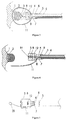
Fig. 1 is a schematic diagram of an implanted medical instrument of the prior art; -
Fig. 2 is a schematic diagram of an implanted medical instrument provided by one embodiment of the present invention; -
Fig. 3 is a cross-sectional view ofFig. 2 ; -
Fig. 4 is a schematic diagram showing the disengagement of a pusher from an implant; -
Fig. 5 is a schematic diagram of one end (a free end) of a connecting wire provided by another embodiment of the present invention; -
Fig. 6 is a cross-sectional view of a connecting wire welded or fixed to a lock by glue according to still another embodiment of the present invention; -
Fig. 7 is a cross-sectional view of a connecting wire fixed on a cylinder according to one embodiment of the present invention; -
Fig. 8 is a cross-sectional view of a control wire having a hook-shaped structure provided by one embodiment of the present invention; -
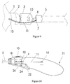
Fig. 9 is a schematic diagram of forming a groove by removing a side wall on one side of a lock hole provided by one embodiment of the present invention; and -
Fig. 10 is a schematic diagram of a control component provided by one embodiment of the present invention. - In order to make the objectives, the technical solutions and the advantages of the present invention more clear, the present invention will be further described in detail with reference to the accompanying drawings and the embodiments. It should be understood that the specific embodiments described here is merely used for explaining the present invention, but not for limiting the present invention.
- One embodiment of the present invention provides an implanted
medical instrument 100, as shown inFig. 2 ,Fig. 3 andFig. 10 , including animplant 1 and a conveying device configured to deliver theimplant 1. The conveying device mainly includes apusher 20 and a control component 21 (as shown inFig. 10 ). A through hole is defined at the distal portion of theimplant 1. In the embodiment, theimplant 1 is a heart occluder. Thepusher 20 includes acatheter 5 and alock 3. - Further as shown in
Fig. 4 to Fig. 10 , aclosure head 2 configured to bring ends of metal wires of theimplant 1 together is arranged on an end portion of theimplant 1. A throughhole 10, through which a connecting wire passes, is defined in a portion of theimplant 1, which is near theclosure head 2. Alock 3 having aninner cavity 8 is arranged on the top end of thecatheter 5. Theinner cavity 8 of thelock 3 is communicated with atube cavity 6 of thecatheter 5. At least onelock hole 7 is defined in thelock 3, and acontrol wire 4 is received in thetube cavity 6 of thecatheter 5. Thecontrol wire 4, a connectingwire 11 and thelock hole 7 are matched with each other to form a plug structure connection. One end of the connectingwire 11 is fixed on thecontrol component 21, and the connectingwire 11 is wound around a screw 19 (as shown inFig. 10 ) and fixed by thescrew 19. The length of the connectingwire 11 may be adjusted by rotating thescrew 19 so as to adjust a distance between theimplant 1 and thelock 3. Another end of the connectingwire 11 extends through theimplant 1, meanwhile crosses theclosure head 2, and then enters into thelock hole 7, and is finally sleeved on thecontrol wire 4. One end of thecontrol wire 4 is fixed on anoperating button 15 on thecontrol component 21, and is fixed by fixingscrews 18. Thecontrol wire 4 can be actuated by thecontrol component 21 to move in thetube cavity 6 till the other end of thecontrol wire 4 passes through the connectingwire 11 or backtracks to be separated from the connectingwire 11. If there is a need to connect theimplant 1 with thecatheter 5, one end of the connectingwire 11 passes through the throughhole 10 and enters thelock hole 7, and then theoperating button 15 is pushed to move towards the direction of theclosure head 2 till thecontrol wire 4 passes through the connectingwire 11. - As shown in
Fig. 10 , a restricting mechanism configured to limit the movement of theoperating button 15 is arranged on thecontrol component 21, and includes asecurity button 22, arotary driving member 24 in contact with thesecurity button 22, and anelastic stopper 26 which is driven by therotary driving member 24 and configured to restrict the movement of theoperating button 15. When thesecurity button 22 is pressed upwards, therotary driving member 24 is rotated around the center itself, i.e., one end of therotary driving member 24 in contact with thesecurity button 22 moves upwards, and one end in contact with theelastic stopper 26 moves downwards. Hence, one end of theelastic stopper 26 is oscillated downwards under the pressure of therotary driving member 24, to release the restriction to theoperating button 15. - The restricting mechanism is operated to make the
operating button 15 move along the direction away from thecatheter 5, thereby ensuring that thecontrol wire 4 is moved along theinner cavity 8 of thelock 3 towards the direction away from theend socket 2 till another end of thecontrol wire 4 is moved into thelock hole 7 and separated from the connectingwire 11. In the absence of any external force, therotary driving member 24 returns to an initial position under the action of a torsion spring. When thesecurity button 22 is pressed, thesecurity button 22 applies force onto therotary driving member 24, and therotary driving member 24 applies force onto thestopper 26, so that thestopper 26 and theoperating button 15 are disengaged from each other. When thesecurity button 22 is released, thesecurity button 22 returns to the initial position, and therotary driving member 24 and thestopper 26 also returns to the initial position. - The
control component 21 is operated to press thesecurity button 22 while pushing theoperating button 15 along a direction close to thescrew 19, thereby ensuring that thecontrol wire 4 is moved along theinner cavity 8 of thelock 3 towards the direction away from theclosure head 2 until another end of thecontrol wire 4 is moved into thelock hole 7 and separated from the connectingwire 11; theimplant 1 and thecatheter 5 are then disengaged. - The
implant 1 may also be a vascular plug used for artery and vein blood vessels, and may also be a thrombus filter or other instruments having a tail end. The structures of these instruments are well known by a person of ordinary skill in the art, and are not described in detail here. - A common heart defect occluder or vascular plug is a mesh structure formed by braiding nickel titanium alloy wires, having a
closure head 2 on one end. In order to achieve the objective of the embodiment, a throughhole 10 may be defined in the nickel-titanium alloy wire (braided wire) close to theclosure head 2 by heat-treatment shaping, and there are a variety of methods for shaping the throughhole 10; e.g., placing a transverse mold bar into a nickel-titanium wire mesh tube during a heat-treatment shaping step; or evenly dividing the nickel-titanium wires to the right and to the left, and binding them into two bundles by using metal wires to form a through hole. The heat-treatment method is well-known to a person of ordinary skill in the art, and is not described in detail. The throughhole 10 may be a gap formed by enclosing nickel-titanium wires mutually, and may also be defined on the implant alone through drilling. Compared with the prior art, since the implant replaces a prior metal lock ring by the through hole, there is no metal brought from the metal lock ring after the implant is implanted into the human body, so that released amount of metal ions is reduced, and the risk that the endothelial tissue may not completely cover the lock ring when the lock ring and the surface of the implant are not fitted closely is also avoided at the same time, thereby reducing thrombus source of the implant. - The
catheter 5 may be a spring tube formed by densely winding a metal wire, and thelock 3 is welded on the top end of thecatheter 5. Thelock 3 is provided with theinner cavity 8 and thelock hole 7. Thecatheter 5 and thelock 3 are coaxial. Theinner cavity 8 of thelock 3 is communicated with thetube cavity 6 of thecatheter 5. Thecontrol wire 4 is received in thetube cavity 6 of thecatheter 5. Thecontrol wire 4 may move in thetube cavity 6 and theinner cavity 8 along the axial direction, and the top end of thecontrol wire 4 may reach thelock hole 7. A distal diameter of thelock 3 is greater than a difference between an inner diameter of a conveying sheath tube and a diameter of theclosure head 2 of theimplant 1 to ensure that theimplant 1 will not drop out of thelock 3 when it is pushed in the conveying sheath tube, thereby avoiding the difficulty of pushing theimplant 1. In this way, the surgical success rate is improved. Of course, in order to ensure proper movement in the sheath, the distal diameter of thelock 3 is also smaller than the inner diameter of the conveying sheath tube at the same time. For example, the diameter of theend socket 2 of theimplant 1 is 1.5 mm, the inner diameter of the conveying sheath tube is 3 mm, and the distal diameter of thelock 3 must be greater than 1.5 mm. Meanwhile, for good match between theclosure head 2 of theimplant 1 and the distal end of thelock 3, aspherical groove 31 may be defined on the distal end of the lock 3 (as shown inFig. 4 ). - The
tube cavity 6 of thecatheter 5 is also provided with a connectingwire 11 inside, and the connectingwire 11 may be a polymer wire and may also be multi-strand metal twisted wires, preferably multi-strand nickel-titanium twisted wires in this embodiment. The tail ends of the connectingwire 11 are combined to pass through theinner cavity 6 of thecatheter 5 and fixed on thecontrol component 21, so that a ring is formed at the distal end of the connectingwire 11. A distal head of the connectingwire 11 passes through the throughhole 10 of theimplant 1 and then is passed through by thecontrol wire 4; after passing through the head of the connectingwire 11, thecontrol wire 4 is propped against the bottom of the distal end of theinner cavity 8 of thelock 3, so as to ultimately play a role of connecting theimplant 1 with thecatheter 5. When theimplant 1 and thecatheter 5 are connected with each other, theimplant 1 under a tensile state should be ensured to directly face thelock 3 of thecatheter 5. The distance between theimplant 1 and thelock 3 of thecatheter 5 may be adjusted and controlled by adjusting the length of the connectingwire 11. - As shown in
Fig. 5 , in addition to the above structure, the connectingwire 11 may also have other various structures: e.g., aring structure 28 is additionally arranged on the head of a single connectingwire 11 and may be formed by a variety of ways, such as knotting the head end of the connectingwire 11, or welding a metal ring on the head. - One end of the
lock 3 is connected to thecatheter 5. The inner diameter of one end of thelock 3 connected to thecatheter 5 is equal to the outer diameter of thecatheter 5 to ensure that thecatheter 5 may be mounted in the inner cavity of this end of thelock 3, with the connection accomplished preferably by laser welding. Another end of thelock 3 is propped against theclosure head 2 of the implant, and the top thereof is closed and also formed with thespherical groove 31 that allows theclosure head 2 to rotate by closely fitting to thespherical groove 31. In the present embodiment, thelock hole 7 can be shaped as a through hole, in order to facilitate the assembly, and a side wall on one side of thelock hole 7 may be removed to form a groove, as shown inFig. 9 . The radial size of one end of thelock 3 close to theimplant 1 is not less than a difference value between the inner diameter of the conveying sheath applied during surgery and the diameter of theend socket 2, while being less than the inner diameter of the conveying sheath; in this way, when theimplant 1 is pushed within the sheath tube, theimplant 1 will not drop out of thelock 3, thereby avoiding difficulties in pushing the implant and improving the surgical success rate. - In this embodiment, in order to facilitate welding the
lock 3 and thecatheter 5, the thickness of an outer wall of a cavity body in one end of thelock 3 connected to thecatheter 5 may be adjusted to be a thickness appropriate for intensified welding, and the appropriate thickness is in the range of 0.1 to 0.5 mm. - In order to facilitate assembling the device, the front end of the
lock 3 may be additionally provided with anobservation hole 12 configured to confirm whether the bottom of the distal end of theinner cavity 8 of thelock 3 is completely propped against thecontrol wire 4. - In order to improve the flexibility of the
catheter 5, a certain length of the front end of thecatheter 5 may be polished, and the polished length is preferably in a range from 5 % to 15 % of the total length of the pusher. In order to facilitate manufacturing thecatheter 5 by laser welding, while avoiding the situations where thecatheter 5 cannot be welded by laser due to the excessive thickness or the catheter being damaged by the laser due to the thickness being too thin, and to ensure the strength of thecatheter 5, the preferable thickness range for polishing thecatheter 5 should not exceed one half of the wall thickness of thecatheter 5. The wall thickness of thecatheter 5 is preferably in the range of 0.3 mm to 0.4 mm, and the thickness of the polished segment of thecatheter 5 is preferably in the range of 0.2 mm to 0.3 mm. - When there is a need to release the
implant 1 during a therapy, thecontrol wire 4 is retracted into thetube cavity 6 of thecatheter 5, so that the head of the connectingwire 11 is not restrained by thecontrol wire 4 to be disengaged from thelock hole 7 of thelock 3. At the same time, thecatheter 5 is dragged, and thecontrol wire 4 may be withdrawn from the inside of the throughhole 10 of theimplant 1 so as to completely separate theimplant 1 from thecatheter 5. - A second embodiment of the present invention is shown in
Fig. 6 . The other mechanisms of the second embodiment are the same as those of the first embodiment, except that the fixation manner of the connecting wire is adjusted. As shown inFig. 6 , the fixed end of the connectingwire 11 may be fixed on the side wall of thelock 3 of thecatheter 5; when the connectingwire 11 is a metal wire, the connection may be accomplished by laser welding or resistance welding and the like; when the connectingwire 11 is a non-metal wire, the connecting may be accomplished by gluing. InFig. 6 , one end of the connectingwire 11 is fixed on a welding spot or aglue dot 29. As shown inFig. 7 , the connectingwire 11 may be fixed on a cylinder 13by a screw; and thecylinder 13 is placed in thetube cavity 6 of thecatheter 5. Thecylinder 13, of which the outer diameter is smaller than the diameter of thetube cavity 6 of thecatheter 5 and greater than the diameter of the adjacentinner cavity 8 of thelock 3, is a cylindrical member with a central throughhole 14, so that thecylinder 13 may be clamped at the distal end of thetube cavity 6 of thecatheter 5. Meanwhile, the outer diameter of the central throughhole 14 is greater than the diameter of thecontrol wire 4, in order to ensure that thecontrol wire 4 may move inside the throughhole 14. - According to the first embodiment, when the
control wire 4 is retracted into thetube cavity 6 of thecatheter 5, the connectingwire 11 may be disengaged from theimplant 1. In this regard, as a third embodiment of the present invention, as shown inFig. 8 , thecontrol wire 4 in the first embodiment is replaced by a control wire 15 (also referred to as 'hook-shaped control wire') with a hook-shaped structure, and the direction of a hook faces towards the proximal end of thecatheter 5. When there is a need to connect theimplant 1, the hook-shaped structure 16 of the hook-shapedcontrol wire 15 is first moved to the leftmost end of theinner cavity 8 or moved until the free end of the hook-shaped structure 16 is located on the left side of the tail end of the connectingwire 11, and then is moved to the right (towards the direction of the control component 12), so that the hook-shaped structure 16 of the hook-shapedcontrol wire 15 hooks the ring (or the ring structure) on the front end of the connectingwire 11 and pulls the hook-shapedcontrol wire 15 back to the proximal end (towards the direction of the control component 12). In this way, the hook-shapedcontrol wire 15 and the connectingwire 11 are connected together. If there is a need to disengage the connectingwire 11, the hook-shapedcontrol wire 15 is pushed until the hook-shaped structure 16 moves to pass through the distal end of thelock hole 7, and the hook-shaped structure 16 is disengaged from the ring (or the ring structure) on the front end of the connectingwire 11. - The above descriptions are merely preferred embodiments of the present invention, but not for limiting the present invention. Any modification, equivalent replacement and improvement done within the spirit and principle of the present invention should be regarded as falling into the protection scope of the present invention.
Claims (11)
- An implant conveying device, wherein the conveying device comprises a pusher, a control component, a connecting wire and a control wire;
the pusher, of which one end is connected to the control component, comprising a tube cavity and a lock hole communicated with the tube cavity;
one end of the control wire is connected to the control component, and the other end thereof is capable of being driven by the control component to be movably accommodated in the tube cavity of the pusher;
one end of the connecting wire is connected to the pusher or to the control component, and the other end thereof is used for passing through an implant and then entering the lock hole;
the control wire is capable of being driven by the control component to pass through the connecting wire to connect the implant with the conveying device, or the control wire is capable of being driven by the control component to be disengaged from the connecting wire to release the implant. - The implant delivery device according to claim 1, wherein the length of the connecting wire between the implant and the pusher is adjustable by the control component, when one end of the connecting wire is fixed in the control component.
- The implant conveying device according to claim 1, wherein the pusher comprises a catheter and a lock, one end of the catheter is connected to the control component, the lock with one end being open comprises an inner cavity, the open end is communicated with another end of the catheter; the lock hole is defined in the lock and vertically communicated with the tube cavity.
- The implant conveying device according to claim 1, wherein an operating button is arranged on the control component, and one end of the control wire is fixed on the operating button.
- The implant conveying device according to claim 4, wherein a restricting mechanism configured to restrict the movement of the operating button is arranged on the control component, the restricting mechanism comprises a security button, a driving member which is in interaction with the security button and provided with a torsion spring, and an elastic stopper which is capable of being driven by the driving member and configured to restrict the movement of the operating button.
- The implant conveying device according to claim 4, wherein an unopened end surface of the lock is provided with a groove.
- The implant conveying device according to claims 1, wherein a ring is formed on another end of the connecting wire and configured for the control wire passing therethrough.
- The implant conveying device according to claim 4, wherein the lock is provided with an observation hole configured to confirm whether the unopened end of the lock is completely propped against the control wire.
- The implant conveying device according to claim 4, wherein one end of the control wire, which is matched with the connecting wire, is bent into a hook-shaped structure; when connecting the implant conveying device with the implant, the hook-shaped structure hooks the connecting wire in a position where the lock hole is located, and pulls the control wire back to a proximal end; wherein the connection is completed when the hook-shaped structure leaves the inner cavity of the lock; when the implant is disengaged from the connecting wire, the control wire is pushed until the hook-shaped structure passes through a distal end of the lock hole.
- An implanted medical instrument, comprising an implant, wherein the implanted medical instrument further comprises an implant conveying device of any one of claims 1 to 9, wherein the implant has a through hole, another end of the connecting wire passes through the through hole and enters the lock hole, and is sleeved on the control wire; the control wire is capable of being driven by the control component to be disengaged from the connecting wire to release the implant.
- The implanted medical instrument according to claim 10, wherein the implant has a mesh structure and a closure head configured to restrain the mesh structure, the through hole is a gap formed by mutually enclosing nickel-titanium alloy wires, or a hole formed on the implant; a manufacturing method of the through hole comprises a step of: forming a through hole on the implant; or placing a transverse mold bar into a nickel-titanium wire mesh tube during a heat-treatment shaping process; or evenly dividing the nickel-titanium wires to the right and to the left, and binding them into two bundles by metal wires to form a through hole.
Applications Claiming Priority (2)
| Application Number | Priority Date | Filing Date | Title |
|---|---|---|---|
| CN201310747039.5A CN103690202B (en) | 2013-12-30 | 2013-12-30 | The conveyer device of implant and implanted medical device |
| PCT/CN2014/090603 WO2015101107A1 (en) | 2013-12-30 | 2014-11-07 | Implant conveying device and implanted medical instrument |
Publications (3)
| Publication Number | Publication Date |
|---|---|
| EP3090692A1 true EP3090692A1 (en) | 2016-11-09 |
| EP3090692A4 EP3090692A4 (en) | 2017-09-20 |
| EP3090692B1 EP3090692B1 (en) | 2019-03-20 |
Family
ID=50351987
Family Applications (1)
| Application Number | Title | Priority Date | Filing Date |
|---|---|---|---|
| EP14875946.7A Active EP3090692B1 (en) | 2013-12-30 | 2014-11-07 | Implant conveying device and medical instrument |
Country Status (4)
| Country | Link |
|---|---|
| US (1) | US10188497B2 (en) |
| EP (1) | EP3090692B1 (en) |
| CN (1) | CN103690202B (en) |
| WO (1) | WO2015101107A1 (en) |
Cited By (1)
| Publication number | Priority date | Publication date | Assignee | Title |
|---|---|---|---|---|
| EP3733094A4 (en) * | 2017-12-28 | 2021-10-06 | Shenzhen Lifetech Respiration Scientific Co., Ltd. | Conveyor for implant having at least one cavity |
Families Citing this family (27)
| Publication number | Priority date | Publication date | Assignee | Title |
|---|---|---|---|---|
| AU2009212393B2 (en) | 2008-02-06 | 2014-07-24 | Ancora Heart, Inc. | Multi-window guide tunnel |
| CN103690202B (en) | 2013-12-30 | 2016-04-20 | 先健科技(深圳)有限公司 | The conveyer device of implant and implanted medical device |
| CN104013482B (en) * | 2014-06-05 | 2016-05-04 | 上海形状记忆合金材料有限公司 | A kind of conveying device for Implantable Medical Device |
| CN104116574A (en) | 2014-07-04 | 2014-10-29 | 先健科技(深圳)有限公司 | Plug and plugging device |
| CN104546242B (en) * | 2014-12-02 | 2017-01-25 | 先健科技(深圳)有限公司 | Delivery devices for implants and implanted medical devices |
| US10980973B2 (en) | 2015-05-12 | 2021-04-20 | Ancora Heart, Inc. | Device and method for releasing catheters from cardiac structures |
| CN105250033B (en) * | 2015-10-20 | 2019-04-02 | 先健科技(深圳)有限公司 | Interventional medical device and its conveying cable body, intervention medical device |
| EP3576644B1 (en) | 2017-03-13 | 2024-10-09 | Boston Scientific Scimed, Inc. | Occlusive medical device system |
| US11191927B2 (en) | 2017-07-31 | 2021-12-07 | Boston Scientific Scimed, Inc. | Dilator with engagement region |
| WO2019035884A1 (en) | 2017-08-15 | 2019-02-21 | Boston Scientific Scimed, Inc. | Occlusive medical device system |
| US10874402B2 (en) | 2017-10-10 | 2020-12-29 | Boston Scientific Scimed, Inc. | Detachable RF energized occlusive device |
| CN111670021B (en) | 2018-02-01 | 2023-08-04 | 波士顿科学国际有限公司 | Medical device release system |
| US11284902B2 (en) | 2018-02-01 | 2022-03-29 | Boston Scientific Scimed, Inc. | Method of making a vascular occlusion device |
| DE102019101163B3 (en) | 2019-01-17 | 2020-06-04 | Schaeffler Technologies AG & Co. KG | Electric drive unit and method for temperature calculation in an electric drive unit |
| DE102020112200A1 (en) | 2019-09-03 | 2021-03-04 | Schaeffler Technologies AG & Co. KG | Electric drive unit, method for operating an electric drive unit and method for temperature calculation |
| US11672946B2 (en) | 2019-09-24 | 2023-06-13 | Boston Scientific Scimed, Inc. | Protection and actuation mechanism for controlled release of implantable embolic devices |
| CN111110302B (en) * | 2019-12-16 | 2021-06-25 | 先健科技(深圳)有限公司 | Conveyor system |
| CN111658026B (en) * | 2020-06-16 | 2024-11-29 | 上海形状记忆合金材料有限公司 | Head end encircling type clamping conveying system |
| EP4404870A4 (en) * | 2021-09-20 | 2024-11-20 | Prodeon Medical Corporation | PLACEMENT AND DEPLOYMENT OF A PROSTATIC IMPLANT |
| CN113576588B (en) * | 2021-09-29 | 2021-12-28 | 北京华脉泰科医疗器械股份有限公司 | Post-implant release device |
| CN114344676B (en) * | 2021-12-29 | 2024-03-29 | 上海臻亿医疗科技有限公司 | Release mechanism and delivery catheter |
| CN115607218B (en) * | 2022-09-28 | 2023-11-07 | 上海心玮医疗科技股份有限公司 | Mechanical release device for intratumoral implant |
| CN115886893A (en) * | 2022-10-17 | 2023-04-04 | 重庆熙科医疗科技有限公司 | Minimally invasive channel implant inserter |
| CN118252648A (en) * | 2022-12-28 | 2024-06-28 | 先健科技(深圳)有限公司 | Implants and implant delivery systems |
| CN118787398B (en) * | 2024-06-26 | 2025-09-12 | 无忧跳动医疗科技(深圳)有限公司 | Implant pushing device and implant pushing system |
| CN121287317B (en) * | 2025-12-10 | 2026-04-21 | 哈尔滨思哲睿智能医疗设备股份有限公司 | Surgical robot control methods and program products |
| CN121446008B (en) * | 2026-01-06 | 2026-04-07 | 苏州中天医疗器械科技有限公司 | Intervention conveying device |
Family Cites Families (35)
| Publication number | Priority date | Publication date | Assignee | Title |
|---|---|---|---|---|
| US5456713A (en) * | 1991-10-25 | 1995-10-10 | Cook Incorporated | Expandable transluminal graft prosthesis for repairs of aneurysm and method for implanting |
| US5372600A (en) * | 1991-10-31 | 1994-12-13 | Instent Inc. | Stent delivery systems |
| IT1269443B (en) * | 1994-01-19 | 1997-04-01 | Stefano Nazari | VASCULAR PROSTHESIS FOR THE REPLACEMENT OR INTERNAL COATING OF MEDIUM AND LARGE DIAMETER BLOOD VESSELS AND DEVICE FOR ITS APPLICATION WITHOUT INTERRUPTION OF BLOOD FLOW |
| US6835185B2 (en) * | 1998-12-21 | 2004-12-28 | Micrus Corporation | Intravascular device deployment mechanism incorporating mechanical detachment |
| JP2003204966A (en) * | 2002-01-16 | 2003-07-22 | Olympus Optical Co Ltd | Medical ligation unit |
| US7550002B2 (en) * | 2002-04-30 | 2009-06-23 | Olympus Corporation | Stent delivery device |
| US7608058B2 (en) | 2002-07-23 | 2009-10-27 | Micrus Corporation | Stretch resistant therapeutic device |
| US7316708B2 (en) * | 2002-12-05 | 2008-01-08 | Cardiac Dimensions, Inc. | Medical device delivery system |
| CN2626433Y (en) * | 2003-05-21 | 2004-07-21 | 卢才义 | Congenital heart disease plugging device with safe release device |
| US9198786B2 (en) * | 2003-09-03 | 2015-12-01 | Bolton Medical, Inc. | Lumen repair device with capture structure |
| JP4805162B2 (en) * | 2003-11-25 | 2011-11-02 | ボストン サイエンティフィック リミテッド | Hemostatic device |
| AU2004315450A1 (en) * | 2004-01-15 | 2005-08-18 | Michael James Wenzler | Hanging device |
| US20060036280A1 (en) * | 2004-08-11 | 2006-02-16 | Concentric Medical, Inc. | Systems and methods for severing occlusive elements from a delivery catheter |
| EP1827247B8 (en) * | 2004-09-24 | 2020-05-06 | W.L. Gore & Associates, Inc. | Occluder device double securement system for delivery/recovery of such occluder device |
| US20060116714A1 (en) * | 2004-11-26 | 2006-06-01 | Ivan Sepetka | Coupling and release devices and methods for their assembly and use |
| US20070011238A1 (en) * | 2005-05-26 | 2007-01-11 | Noam Rechter | Communication device and method |
| US7799052B2 (en) * | 2005-06-02 | 2010-09-21 | Codman & Shurtleff, Inc. | Stretch resistant embolic coil delivery system with mechanical release mechanism |
| US20060276827A1 (en) * | 2005-06-02 | 2006-12-07 | Vladimir Mitelberg | Stretch resistant embolic coil delivery system with mechanical release mechanism |
| US7955354B2 (en) * | 2005-11-14 | 2011-06-07 | Occlutech Gmbh | Occlusion device and surgical instrument and method for its implantation/explantation |
| US9034006B2 (en) * | 2005-12-01 | 2015-05-19 | Atritech, Inc. | Method and apparatus for retrieving an embolized implant |
| WO2007070792A2 (en) * | 2005-12-13 | 2007-06-21 | Cordis Development Corporation | Actuator handle for use with medical device deployment systems |
| EP1821088A1 (en) * | 2006-02-16 | 2007-08-22 | IEE International Electronics & Engineering S.A.R.L. | Pressure sensing mat |
| US8157837B2 (en) * | 2006-03-13 | 2012-04-17 | Pneumrx, Inc. | Minimally invasive lung volume reduction device and method |
| FR2899096B1 (en) * | 2006-04-04 | 2008-12-05 | Perouse Soc Par Actions Simpli | DEVICE FOR TREATING A CIRCULATION CIRCULATION OF THE BLOOD AND METHOD OF PREPARING SAID DEVICE |
| US9220487B2 (en) * | 2006-08-09 | 2015-12-29 | Coherex Medical, Inc. | Devices for reducing the size of an internal tissue opening |
| US20080306503A1 (en) * | 2006-11-20 | 2008-12-11 | Boston Scientific Scimed, Inc. | Mechanically detachable vaso-occlusive device |
| US8834515B2 (en) | 2006-11-20 | 2014-09-16 | Boston Scientific Scimed, Inc. | Mechanically detachable vaso-occlusive device |
| US8034094B2 (en) | 2008-06-11 | 2011-10-11 | Olympus Medical Systems Corp. | Stent delivery system and stent delivery method |
| WO2010121049A1 (en) * | 2009-04-15 | 2010-10-21 | Microvention, Inc. | Implant delivery system |
| WO2012003317A1 (en) * | 2010-07-02 | 2012-01-05 | Alex Javois | Left atrial appendage occlusion device |
| CN101933839B (en) * | 2010-08-26 | 2013-09-25 | 先健科技(深圳)有限公司 | Connecting device for mediatory type medical devices and using method thereof |
| CN201905938U (en) * | 2010-11-30 | 2011-07-27 | 上海长海医院 | Conveying and recovery device for transcatheter minimally invasive intervention operation |
| CN103690202B (en) * | 2013-12-30 | 2016-04-20 | 先健科技(深圳)有限公司 | The conveyer device of implant and implanted medical device |
| CN203662815U (en) * | 2013-12-30 | 2014-06-25 | 先健科技(深圳)有限公司 | Implant conveying device and implanted medical instrument |
| CN104116574A (en) | 2014-07-04 | 2014-10-29 | 先健科技(深圳)有限公司 | Plug and plugging device |
-
2013
- 2013-12-30 CN CN201310747039.5A patent/CN103690202B/en active Active
-
2014
- 2014-11-07 EP EP14875946.7A patent/EP3090692B1/en active Active
- 2014-11-07 US US15/108,021 patent/US10188497B2/en active Active
- 2014-11-07 WO PCT/CN2014/090603 patent/WO2015101107A1/en not_active Ceased
Cited By (2)
| Publication number | Priority date | Publication date | Assignee | Title |
|---|---|---|---|---|
| EP3733094A4 (en) * | 2017-12-28 | 2021-10-06 | Shenzhen Lifetech Respiration Scientific Co., Ltd. | Conveyor for implant having at least one cavity |
| US11717427B2 (en) | 2017-12-28 | 2023-08-08 | Shenzhen Lifetech Respiration Scientific Co., Ltd. | Conveyor for implant having at least one cavity |
Also Published As
| Publication number | Publication date |
|---|---|
| US10188497B2 (en) | 2019-01-29 |
| EP3090692B1 (en) | 2019-03-20 |
| US20160317274A1 (en) | 2016-11-03 |
| WO2015101107A1 (en) | 2015-07-09 |
| CN103690202A (en) | 2014-04-02 |
| EP3090692A4 (en) | 2017-09-20 |
| CN103690202B (en) | 2016-04-20 |
Similar Documents
| Publication | Publication Date | Title |
|---|---|---|
| US10188497B2 (en) | Implant conveying device and implanted medical instrument | |
| US11849956B2 (en) | Devices and methods for delivering an implant to a vascular disorder | |
| US20230218300A1 (en) | Detachable implantable devices | |
| US7226466B2 (en) | Flexible delivery system | |
| DE602005004960T2 (en) | Insertion device for an embolic coil with a U-shaped fiber release mechanism | |
| US9700322B2 (en) | Mechanical embolization delivery apparatus and methods | |
| EP3398567B1 (en) | Interventional medical system | |
| US10966727B2 (en) | Devices and methods for delivering an implant to a vascular disorder | |
| EP3064154A1 (en) | Implantable device detachment systems and associated devices | |
| EP2967576B1 (en) | Delivery and detachment mechanisms for vascular implants | |
| US20130211495A1 (en) | Interference-relief type delivery detachment systems | |
| JP2017517339A (en) | Lung volume reduced elastic implants and instruments | |
| CN113413186B (en) | Embolic coil system | |
| EP3363408B1 (en) | Lung-volume-reduction elastic implant and lung-volume-reduction instrument | |
| US10639043B2 (en) | Vasculature occlusion device detachment system with tapered corewire and heater activated fiber detachment | |
| CN203662815U (en) | Implant conveying device and implanted medical instrument | |
| EP4003190B1 (en) | Embolic device delivery system | |
| CN216777122U (en) | Closure device for tissue defects | |
| CN120788655A (en) | Disruptor and conveying system | |
| AU2015227527A1 (en) | A vasculature occlusion device detachment system with tapered corewire and heater activated fiber detachment | |
| CN117379222A (en) | Embolic protection device specially designed for curved blood vessels, especially cerebral blood vessels |
Legal Events
| Date | Code | Title | Description |
|---|---|---|---|
| PUAI | Public reference made under article 153(3) epc to a published international application that has entered the european phase |
Free format text: ORIGINAL CODE: 0009012 |
|
| 17P | Request for examination filed |
Effective date: 20160729 |
|
| AK | Designated contracting states |
Kind code of ref document: A1 Designated state(s): AL AT BE BG CH CY CZ DE DK EE ES FI FR GB GR HR HU IE IS IT LI LT LU LV MC MK MT NL NO PL PT RO RS SE SI SK SM TR |
|
| AX | Request for extension of the european patent |
Extension state: BA ME |
|
| DAX | Request for extension of the european patent (deleted) | ||
| A4 | Supplementary search report drawn up and despatched |
Effective date: 20170821 |
|
| RIC1 | Information provided on ipc code assigned before grant |
Ipc: A61F 2/01 20060101ALN20170814BHEP Ipc: A61F 2/02 20060101ALI20170814BHEP Ipc: A61B 17/12 20060101AFI20170814BHEP |
|
| GRAP | Despatch of communication of intention to grant a patent |
Free format text: ORIGINAL CODE: EPIDOSNIGR1 |
|
| STAA | Information on the status of an ep patent application or granted ep patent |
Free format text: STATUS: GRANT OF PATENT IS INTENDED |
|
| RIC1 | Information provided on ipc code assigned before grant |
Ipc: A61B 17/12 20060101AFI20180918BHEP Ipc: A61F 2/02 20060101ALI20180918BHEP Ipc: A61F 2/01 20060101ALN20180918BHEP |
|
| INTG | Intention to grant announced |
Effective date: 20181005 |
|
| GRAS | Grant fee paid |
Free format text: ORIGINAL CODE: EPIDOSNIGR3 |
|
| GRAA | (expected) grant |
Free format text: ORIGINAL CODE: 0009210 |
|
| STAA | Information on the status of an ep patent application or granted ep patent |
Free format text: STATUS: THE PATENT HAS BEEN GRANTED |
|
| AK | Designated contracting states |
Kind code of ref document: B1 Designated state(s): AL AT BE BG CH CY CZ DE DK EE ES FI FR GB GR HR HU IE IS IT LI LT LU LV MC MK MT NL NO PL PT RO RS SE SI SK SM TR |
|
| REG | Reference to a national code |
Ref country code: GB Ref legal event code: FG4D |
|
| REG | Reference to a national code |
Ref country code: CH Ref legal event code: EP |
|
| REG | Reference to a national code |
Ref country code: DE Ref legal event code: R096 Ref document number: 602014043426 Country of ref document: DE |
|
| REG | Reference to a national code |
Ref country code: AT Ref legal event code: REF Ref document number: 1109664 Country of ref document: AT Kind code of ref document: T Effective date: 20190415 |
|
| REG | Reference to a national code |
Ref country code: IE Ref legal event code: FG4D |
|
| REG | Reference to a national code |
Ref country code: NL Ref legal event code: MP Effective date: 20190320 |
|
| PG25 | Lapsed in a contracting state [announced via postgrant information from national office to epo] |
Ref country code: FI Free format text: LAPSE BECAUSE OF FAILURE TO SUBMIT A TRANSLATION OF THE DESCRIPTION OR TO PAY THE FEE WITHIN THE PRESCRIBED TIME-LIMIT Effective date: 20190320 Ref country code: NO Free format text: LAPSE BECAUSE OF FAILURE TO SUBMIT A TRANSLATION OF THE DESCRIPTION OR TO PAY THE FEE WITHIN THE PRESCRIBED TIME-LIMIT Effective date: 20190620 Ref country code: SE Free format text: LAPSE BECAUSE OF FAILURE TO SUBMIT A TRANSLATION OF THE DESCRIPTION OR TO PAY THE FEE WITHIN THE PRESCRIBED TIME-LIMIT Effective date: 20190320 Ref country code: LT Free format text: LAPSE BECAUSE OF FAILURE TO SUBMIT A TRANSLATION OF THE DESCRIPTION OR TO PAY THE FEE WITHIN THE PRESCRIBED TIME-LIMIT Effective date: 20190320 |
|
| REG | Reference to a national code |
Ref country code: LT Ref legal event code: MG4D |
|
| PG25 | Lapsed in a contracting state [announced via postgrant information from national office to epo] |
Ref country code: NL Free format text: LAPSE BECAUSE OF FAILURE TO SUBMIT A TRANSLATION OF THE DESCRIPTION OR TO PAY THE FEE WITHIN THE PRESCRIBED TIME-LIMIT Effective date: 20190320 Ref country code: HR Free format text: LAPSE BECAUSE OF FAILURE TO SUBMIT A TRANSLATION OF THE DESCRIPTION OR TO PAY THE FEE WITHIN THE PRESCRIBED TIME-LIMIT Effective date: 20190320 Ref country code: RS Free format text: LAPSE BECAUSE OF FAILURE TO SUBMIT A TRANSLATION OF THE DESCRIPTION OR TO PAY THE FEE WITHIN THE PRESCRIBED TIME-LIMIT Effective date: 20190320 Ref country code: BG Free format text: LAPSE BECAUSE OF FAILURE TO SUBMIT A TRANSLATION OF THE DESCRIPTION OR TO PAY THE FEE WITHIN THE PRESCRIBED TIME-LIMIT Effective date: 20190620 Ref country code: GR Free format text: LAPSE BECAUSE OF FAILURE TO SUBMIT A TRANSLATION OF THE DESCRIPTION OR TO PAY THE FEE WITHIN THE PRESCRIBED TIME-LIMIT Effective date: 20190621 Ref country code: LV Free format text: LAPSE BECAUSE OF FAILURE TO SUBMIT A TRANSLATION OF THE DESCRIPTION OR TO PAY THE FEE WITHIN THE PRESCRIBED TIME-LIMIT Effective date: 20190320 |
|
| REG | Reference to a national code |
Ref country code: AT Ref legal event code: MK05 Ref document number: 1109664 Country of ref document: AT Kind code of ref document: T Effective date: 20190320 |
|
| PG25 | Lapsed in a contracting state [announced via postgrant information from national office to epo] |
Ref country code: EE Free format text: LAPSE BECAUSE OF FAILURE TO SUBMIT A TRANSLATION OF THE DESCRIPTION OR TO PAY THE FEE WITHIN THE PRESCRIBED TIME-LIMIT Effective date: 20190320 Ref country code: SK Free format text: LAPSE BECAUSE OF FAILURE TO SUBMIT A TRANSLATION OF THE DESCRIPTION OR TO PAY THE FEE WITHIN THE PRESCRIBED TIME-LIMIT Effective date: 20190320 Ref country code: PT Free format text: LAPSE BECAUSE OF FAILURE TO SUBMIT A TRANSLATION OF THE DESCRIPTION OR TO PAY THE FEE WITHIN THE PRESCRIBED TIME-LIMIT Effective date: 20190720 Ref country code: IT Free format text: LAPSE BECAUSE OF FAILURE TO SUBMIT A TRANSLATION OF THE DESCRIPTION OR TO PAY THE FEE WITHIN THE PRESCRIBED TIME-LIMIT Effective date: 20190320 Ref country code: CZ Free format text: LAPSE BECAUSE OF FAILURE TO SUBMIT A TRANSLATION OF THE DESCRIPTION OR TO PAY THE FEE WITHIN THE PRESCRIBED TIME-LIMIT Effective date: 20190320 Ref country code: AL Free format text: LAPSE BECAUSE OF FAILURE TO SUBMIT A TRANSLATION OF THE DESCRIPTION OR TO PAY THE FEE WITHIN THE PRESCRIBED TIME-LIMIT Effective date: 20190320 Ref country code: RO Free format text: LAPSE BECAUSE OF FAILURE TO SUBMIT A TRANSLATION OF THE DESCRIPTION OR TO PAY THE FEE WITHIN THE PRESCRIBED TIME-LIMIT Effective date: 20190320 Ref country code: ES Free format text: LAPSE BECAUSE OF FAILURE TO SUBMIT A TRANSLATION OF THE DESCRIPTION OR TO PAY THE FEE WITHIN THE PRESCRIBED TIME-LIMIT Effective date: 20190320 |
|
| PG25 | Lapsed in a contracting state [announced via postgrant information from national office to epo] |
Ref country code: SM Free format text: LAPSE BECAUSE OF FAILURE TO SUBMIT A TRANSLATION OF THE DESCRIPTION OR TO PAY THE FEE WITHIN THE PRESCRIBED TIME-LIMIT Effective date: 20190320 Ref country code: PL Free format text: LAPSE BECAUSE OF FAILURE TO SUBMIT A TRANSLATION OF THE DESCRIPTION OR TO PAY THE FEE WITHIN THE PRESCRIBED TIME-LIMIT Effective date: 20190320 |
|
| PG25 | Lapsed in a contracting state [announced via postgrant information from national office to epo] |
Ref country code: AT Free format text: LAPSE BECAUSE OF FAILURE TO SUBMIT A TRANSLATION OF THE DESCRIPTION OR TO PAY THE FEE WITHIN THE PRESCRIBED TIME-LIMIT Effective date: 20190320 Ref country code: IS Free format text: LAPSE BECAUSE OF FAILURE TO SUBMIT A TRANSLATION OF THE DESCRIPTION OR TO PAY THE FEE WITHIN THE PRESCRIBED TIME-LIMIT Effective date: 20190720 |
|
| REG | Reference to a national code |
Ref country code: DE Ref legal event code: R097 Ref document number: 602014043426 Country of ref document: DE |
|
| PLBE | No opposition filed within time limit |
Free format text: ORIGINAL CODE: 0009261 |
|
| STAA | Information on the status of an ep patent application or granted ep patent |
Free format text: STATUS: NO OPPOSITION FILED WITHIN TIME LIMIT |
|
| PG25 | Lapsed in a contracting state [announced via postgrant information from national office to epo] |
Ref country code: DK Free format text: LAPSE BECAUSE OF FAILURE TO SUBMIT A TRANSLATION OF THE DESCRIPTION OR TO PAY THE FEE WITHIN THE PRESCRIBED TIME-LIMIT Effective date: 20190320 |
|
| REG | Reference to a national code |
Ref country code: DE Ref legal event code: R082 Ref document number: 602014043426 Country of ref document: DE Representative=s name: PRINZ & PARTNER MBB PATENT- UND RECHTSANWAELTE, DE Ref country code: DE Ref legal event code: R082 Ref document number: 602014043426 Country of ref document: DE Representative=s name: PRINZ & PARTNER MBB PATENTANWAELTE RECHTSANWAE, DE |
|
| 26N | No opposition filed |
Effective date: 20200102 |
|
| PG25 | Lapsed in a contracting state [announced via postgrant information from national office to epo] |
Ref country code: SI Free format text: LAPSE BECAUSE OF FAILURE TO SUBMIT A TRANSLATION OF THE DESCRIPTION OR TO PAY THE FEE WITHIN THE PRESCRIBED TIME-LIMIT Effective date: 20190320 |
|
| PG25 | Lapsed in a contracting state [announced via postgrant information from national office to epo] |
Ref country code: TR Free format text: LAPSE BECAUSE OF FAILURE TO SUBMIT A TRANSLATION OF THE DESCRIPTION OR TO PAY THE FEE WITHIN THE PRESCRIBED TIME-LIMIT Effective date: 20190320 |
|
| REG | Reference to a national code |
Ref country code: DE Ref legal event code: R082 Ref document number: 602014043426 Country of ref document: DE Representative=s name: PRINZ & PARTNER MBB PATENTANWAELTE RECHTSANWAE, DE |
|
| REG | Reference to a national code |
Ref country code: CH Ref legal event code: PL |
|
| PG25 | Lapsed in a contracting state [announced via postgrant information from national office to epo] |
Ref country code: CH Free format text: LAPSE BECAUSE OF NON-PAYMENT OF DUE FEES Effective date: 20191130 Ref country code: LU Free format text: LAPSE BECAUSE OF NON-PAYMENT OF DUE FEES Effective date: 20191107 Ref country code: LI Free format text: LAPSE BECAUSE OF NON-PAYMENT OF DUE FEES Effective date: 20191130 Ref country code: MC Free format text: LAPSE BECAUSE OF FAILURE TO SUBMIT A TRANSLATION OF THE DESCRIPTION OR TO PAY THE FEE WITHIN THE PRESCRIBED TIME-LIMIT Effective date: 20190320 |
|
| REG | Reference to a national code |
Ref country code: BE Ref legal event code: MM Effective date: 20191130 |
|
| PG25 | Lapsed in a contracting state [announced via postgrant information from national office to epo] |
Ref country code: IE Free format text: LAPSE BECAUSE OF NON-PAYMENT OF DUE FEES Effective date: 20191107 |
|
| PG25 | Lapsed in a contracting state [announced via postgrant information from national office to epo] |
Ref country code: BE Free format text: LAPSE BECAUSE OF NON-PAYMENT OF DUE FEES Effective date: 20191130 |
|
| PG25 | Lapsed in a contracting state [announced via postgrant information from national office to epo] |
Ref country code: CY Free format text: LAPSE BECAUSE OF FAILURE TO SUBMIT A TRANSLATION OF THE DESCRIPTION OR TO PAY THE FEE WITHIN THE PRESCRIBED TIME-LIMIT Effective date: 20190320 |
|
| PG25 | Lapsed in a contracting state [announced via postgrant information from national office to epo] |
Ref country code: HU Free format text: LAPSE BECAUSE OF FAILURE TO SUBMIT A TRANSLATION OF THE DESCRIPTION OR TO PAY THE FEE WITHIN THE PRESCRIBED TIME-LIMIT; INVALID AB INITIO Effective date: 20141107 Ref country code: MT Free format text: LAPSE BECAUSE OF FAILURE TO SUBMIT A TRANSLATION OF THE DESCRIPTION OR TO PAY THE FEE WITHIN THE PRESCRIBED TIME-LIMIT Effective date: 20190320 |
|
| PG25 | Lapsed in a contracting state [announced via postgrant information from national office to epo] |
Ref country code: MK Free format text: LAPSE BECAUSE OF FAILURE TO SUBMIT A TRANSLATION OF THE DESCRIPTION OR TO PAY THE FEE WITHIN THE PRESCRIBED TIME-LIMIT Effective date: 20190320 |
|
| PGFP | Annual fee paid to national office [announced via postgrant information from national office to epo] |
Ref country code: DE Payment date: 20251117 Year of fee payment: 12 |
|
| PGFP | Annual fee paid to national office [announced via postgrant information from national office to epo] |
Ref country code: GB Payment date: 20251126 Year of fee payment: 12 |
|
| PGFP | Annual fee paid to national office [announced via postgrant information from national office to epo] |
Ref country code: FR Payment date: 20251127 Year of fee payment: 12 |