EP3089927B1 - Beverage dispensing module and flexible pouch - Google Patents
Beverage dispensing module and flexible pouch Download PDFInfo
- Publication number
- EP3089927B1 EP3089927B1 EP14824006.2A EP14824006A EP3089927B1 EP 3089927 B1 EP3089927 B1 EP 3089927B1 EP 14824006 A EP14824006 A EP 14824006A EP 3089927 B1 EP3089927 B1 EP 3089927B1
- Authority
- EP
- European Patent Office
- Prior art keywords
- roller
- pouch
- beverage
- container
- beverage dispensing
- Prior art date
- Legal status (The legal status is an assumption and is not a legal conclusion. Google has not performed a legal analysis and makes no representation as to the accuracy of the status listed.)
- Not-in-force
Links
- 235000013361 beverage Nutrition 0.000 title claims description 119
- 239000012530 fluid Substances 0.000 claims description 8
- 239000000463 material Substances 0.000 description 21
- 238000010276 construction Methods 0.000 description 13
- 239000010410 layer Substances 0.000 description 9
- 235000013334 alcoholic beverage Nutrition 0.000 description 6
- 239000007788 liquid Substances 0.000 description 6
- LFQSCWFLJHTTHZ-UHFFFAOYSA-N Ethanol Chemical compound CCO LFQSCWFLJHTTHZ-UHFFFAOYSA-N 0.000 description 5
- 239000000853 adhesive Substances 0.000 description 4
- 230000001070 adhesive effect Effects 0.000 description 4
- 239000011521 glass Substances 0.000 description 4
- 239000004033 plastic Substances 0.000 description 4
- 229920003023 plastic Polymers 0.000 description 4
- PNEYBMLMFCGWSK-UHFFFAOYSA-N Alumina Chemical compound [O-2].[O-2].[O-2].[Al+3].[Al+3] PNEYBMLMFCGWSK-UHFFFAOYSA-N 0.000 description 3
- 238000007373 indentation Methods 0.000 description 3
- 238000001802 infusion Methods 0.000 description 3
- 229920000139 polyethylene terephthalate Polymers 0.000 description 3
- 239000005020 polyethylene terephthalate Substances 0.000 description 3
- 238000004064 recycling Methods 0.000 description 3
- 238000005096 rolling process Methods 0.000 description 3
- -1 theraband Polymers 0.000 description 3
- XLYOFNOQVPJJNP-UHFFFAOYSA-N water Substances O XLYOFNOQVPJJNP-UHFFFAOYSA-N 0.000 description 3
- 229920000219 Ethylene vinyl alcohol Polymers 0.000 description 2
- 239000004698 Polyethylene Substances 0.000 description 2
- 239000004743 Polypropylene Substances 0.000 description 2
- 239000004411 aluminium Substances 0.000 description 2
- 229910052782 aluminium Inorganic materials 0.000 description 2
- XAGFODPZIPBFFR-UHFFFAOYSA-N aluminium Chemical compound [Al] XAGFODPZIPBFFR-UHFFFAOYSA-N 0.000 description 2
- 238000004891 communication Methods 0.000 description 2
- 235000008504 concentrate Nutrition 0.000 description 2
- 230000003247 decreasing effect Effects 0.000 description 2
- 239000004715 ethylene vinyl alcohol Substances 0.000 description 2
- 235000020094 liqueur Nutrition 0.000 description 2
- 239000012528 membrane Substances 0.000 description 2
- 229910052751 metal Inorganic materials 0.000 description 2
- 239000002184 metal Substances 0.000 description 2
- 239000000123 paper Substances 0.000 description 2
- 229920000642 polymer Polymers 0.000 description 2
- 238000003825 pressing Methods 0.000 description 2
- 238000003860 storage Methods 0.000 description 2
- 238000003466 welding Methods 0.000 description 2
- 235000012550 Pimpinella anisum Nutrition 0.000 description 1
- 240000004760 Pimpinella anisum Species 0.000 description 1
- 239000004952 Polyamide Substances 0.000 description 1
- VYPSYNLAJGMNEJ-UHFFFAOYSA-N Silicium dioxide Chemical compound O=[Si]=O VYPSYNLAJGMNEJ-UHFFFAOYSA-N 0.000 description 1
- 229910000831 Steel Inorganic materials 0.000 description 1
- 230000002745 absorbent Effects 0.000 description 1
- 239000002250 absorbent Substances 0.000 description 1
- 230000001476 alcoholic effect Effects 0.000 description 1
- 238000004873 anchoring Methods 0.000 description 1
- QVGXLLKOCUKJST-UHFFFAOYSA-N atomic oxygen Chemical compound [O] QVGXLLKOCUKJST-UHFFFAOYSA-N 0.000 description 1
- 235000013405 beer Nutrition 0.000 description 1
- 238000005452 bending Methods 0.000 description 1
- 230000005540 biological transmission Effects 0.000 description 1
- 230000015572 biosynthetic process Effects 0.000 description 1
- 235000013532 brandy Nutrition 0.000 description 1
- 229920005549 butyl rubber Polymers 0.000 description 1
- 235000019993 champagne Nutrition 0.000 description 1
- 235000016213 coffee Nutrition 0.000 description 1
- 235000013353 coffee beverage Nutrition 0.000 description 1
- 235000020057 cognac Nutrition 0.000 description 1
- 239000012141 concentrate Substances 0.000 description 1
- 230000008602 contraction Effects 0.000 description 1
- 230000001276 controlling effect Effects 0.000 description 1
- 230000007423 decrease Effects 0.000 description 1
- 230000002542 deteriorative effect Effects 0.000 description 1
- 230000000694 effects Effects 0.000 description 1
- 230000005489 elastic deformation Effects 0.000 description 1
- 229920001971 elastomer Polymers 0.000 description 1
- UFRKOOWSQGXVKV-UHFFFAOYSA-N ethene;ethenol Chemical compound C=C.OC=C UFRKOOWSQGXVKV-UHFFFAOYSA-N 0.000 description 1
- 238000001704 evaporation Methods 0.000 description 1
- 230000008020 evaporation Effects 0.000 description 1
- 239000000796 flavoring agent Substances 0.000 description 1
- 235000019634 flavors Nutrition 0.000 description 1
- 239000011888 foil Substances 0.000 description 1
- 235000013531 gin Nutrition 0.000 description 1
- 230000005484 gravity Effects 0.000 description 1
- RZXDTJIXPSCHCI-UHFFFAOYSA-N hexa-1,5-diene-2,5-diol Chemical compound OC(=C)CCC(O)=C RZXDTJIXPSCHCI-UHFFFAOYSA-N 0.000 description 1
- 230000001939 inductive effect Effects 0.000 description 1
- 238000005304 joining Methods 0.000 description 1
- 229920000126 latex Polymers 0.000 description 1
- 239000004816 latex Substances 0.000 description 1
- 239000003562 lightweight material Substances 0.000 description 1
- 230000013011 mating Effects 0.000 description 1
- 238000000034 method Methods 0.000 description 1
- 239000000203 mixture Substances 0.000 description 1
- 239000002991 molded plastic Substances 0.000 description 1
- 229910052760 oxygen Inorganic materials 0.000 description 1
- 239000001301 oxygen Substances 0.000 description 1
- 229920001084 poly(chloroprene) Polymers 0.000 description 1
- 229920002647 polyamide Polymers 0.000 description 1
- 229920000573 polyethylene Polymers 0.000 description 1
- 229920001155 polypropylene Polymers 0.000 description 1
- 229920001296 polysiloxane Polymers 0.000 description 1
- 230000001105 regulatory effect Effects 0.000 description 1
- 239000005060 rubber Substances 0.000 description 1
- 235000013533 rum Nutrition 0.000 description 1
- 238000007789 sealing Methods 0.000 description 1
- 238000000926 separation method Methods 0.000 description 1
- 239000008257 shaving cream Substances 0.000 description 1
- 229910052814 silicon oxide Inorganic materials 0.000 description 1
- 229920002379 silicone rubber Polymers 0.000 description 1
- 239000002356 single layer Substances 0.000 description 1
- 235000014214 soft drink Nutrition 0.000 description 1
- 239000007787 solid Substances 0.000 description 1
- 235000015096 spirit Nutrition 0.000 description 1
- 239000010959 steel Substances 0.000 description 1
- 235000013529 tequila Nutrition 0.000 description 1
- 229920002725 thermoplastic elastomer Polymers 0.000 description 1
- 239000010409 thin film Substances 0.000 description 1
- 239000000606 toothpaste Substances 0.000 description 1
- 229940034610 toothpaste Drugs 0.000 description 1
- 210000003462 vein Anatomy 0.000 description 1
- 235000013522 vodka Nutrition 0.000 description 1
- 235000015041 whisky Nutrition 0.000 description 1
- 238000004804 winding Methods 0.000 description 1
- 235000014101 wine Nutrition 0.000 description 1
Images


Classifications
-
- B—PERFORMING OPERATIONS; TRANSPORTING
- B67—OPENING, CLOSING OR CLEANING BOTTLES, JARS OR SIMILAR CONTAINERS; LIQUID HANDLING
- B67D—DISPENSING, DELIVERING OR TRANSFERRING LIQUIDS, NOT OTHERWISE PROVIDED FOR
- B67D7/00—Apparatus or devices for transferring liquids from bulk storage containers or reservoirs into vehicles or into portable containers, e.g. for retail sale purposes
- B67D7/02—Apparatus or devices for transferring liquids from bulk storage containers or reservoirs into vehicles or into portable containers, e.g. for retail sale purposes for transferring liquids other than fuel or lubricants
- B67D7/0216—Apparatus or devices for transferring liquids from bulk storage containers or reservoirs into vehicles or into portable containers, e.g. for retail sale purposes for transferring liquids other than fuel or lubricants by squeezing collapsible or flexible storage containers
-
- B—PERFORMING OPERATIONS; TRANSPORTING
- B65—CONVEYING; PACKING; STORING; HANDLING THIN OR FILAMENTARY MATERIAL
- B65D—CONTAINERS FOR STORAGE OR TRANSPORT OF ARTICLES OR MATERIALS, e.g. BAGS, BARRELS, BOTTLES, BOXES, CANS, CARTONS, CRATES, DRUMS, JARS, TANKS, HOPPERS, FORWARDING CONTAINERS; ACCESSORIES, CLOSURES, OR FITTINGS THEREFOR; PACKAGING ELEMENTS; PACKAGES
- B65D75/00—Packages comprising articles or materials partially or wholly enclosed in strips, sheets, blanks, tubes, or webs of flexible sheet material, e.g. in folded wrappers
- B65D75/52—Details
- B65D75/58—Opening or contents-removing devices added or incorporated during package manufacture
- B65D75/5861—Spouts
- B65D75/5872—Non-integral spouts
- B65D75/5883—Non-integral spouts connected to the package at the sealed junction of two package walls
-
- B—PERFORMING OPERATIONS; TRANSPORTING
- B65—CONVEYING; PACKING; STORING; HANDLING THIN OR FILAMENTARY MATERIAL
- B65D—CONTAINERS FOR STORAGE OR TRANSPORT OF ARTICLES OR MATERIALS, e.g. BAGS, BARRELS, BOTTLES, BOXES, CANS, CARTONS, CRATES, DRUMS, JARS, TANKS, HOPPERS, FORWARDING CONTAINERS; ACCESSORIES, CLOSURES, OR FITTINGS THEREFOR; PACKAGING ELEMENTS; PACKAGES
- B65D85/00—Containers, packaging elements or packages, specially adapted for particular articles or materials
- B65D85/70—Containers, packaging elements or packages, specially adapted for particular articles or materials for materials not otherwise provided for
- B65D85/72—Containers, packaging elements or packages, specially adapted for particular articles or materials for materials not otherwise provided for for edible or potable liquids, semiliquids, or plastic or pasty materials
-
- B—PERFORMING OPERATIONS; TRANSPORTING
- B67—OPENING, CLOSING OR CLEANING BOTTLES, JARS OR SIMILAR CONTAINERS; LIQUID HANDLING
- B67D—DISPENSING, DELIVERING OR TRANSFERRING LIQUIDS, NOT OTHERWISE PROVIDED FOR
- B67D1/00—Apparatus or devices for dispensing beverages on draught
- B67D1/0001—Apparatus or devices for dispensing beverages on draught by squeezing collapsible or flexible storage containers
-
- B—PERFORMING OPERATIONS; TRANSPORTING
- B67—OPENING, CLOSING OR CLEANING BOTTLES, JARS OR SIMILAR CONTAINERS; LIQUID HANDLING
- B67D—DISPENSING, DELIVERING OR TRANSFERRING LIQUIDS, NOT OTHERWISE PROVIDED FOR
- B67D1/00—Apparatus or devices for dispensing beverages on draught
- B67D1/08—Details
- B67D1/0801—Details of beverage containers, e.g. casks, kegs
-
- B—PERFORMING OPERATIONS; TRANSPORTING
- B67—OPENING, CLOSING OR CLEANING BOTTLES, JARS OR SIMILAR CONTAINERS; LIQUID HANDLING
- B67D—DISPENSING, DELIVERING OR TRANSFERRING LIQUIDS, NOT OTHERWISE PROVIDED FOR
- B67D1/00—Apparatus or devices for dispensing beverages on draught
- B67D1/08—Details
- B67D1/12—Flow or pressure control devices or systems, e.g. valves, gas pressure control, level control in storage containers
- B67D1/1277—Flow control valves
- B67D1/1279—Flow control valves regulating the flow
- B67D1/1281—Flow control valves regulating the flow responsive to pressure
-
- B—PERFORMING OPERATIONS; TRANSPORTING
- B65—CONVEYING; PACKING; STORING; HANDLING THIN OR FILAMENTARY MATERIAL
- B65D—CONTAINERS FOR STORAGE OR TRANSPORT OF ARTICLES OR MATERIALS, e.g. BAGS, BARRELS, BOTTLES, BOXES, CANS, CARTONS, CRATES, DRUMS, JARS, TANKS, HOPPERS, FORWARDING CONTAINERS; ACCESSORIES, CLOSURES, OR FITTINGS THEREFOR; PACKAGING ELEMENTS; PACKAGES
- B65D75/00—Packages comprising articles or materials partially or wholly enclosed in strips, sheets, blanks, tubes, or webs of flexible sheet material, e.g. in folded wrappers
- B65D75/52—Details
- B65D75/54—Cards, coupons, or other inserts or accessories
-
- B—PERFORMING OPERATIONS; TRANSPORTING
- B67—OPENING, CLOSING OR CLEANING BOTTLES, JARS OR SIMILAR CONTAINERS; LIQUID HANDLING
- B67D—DISPENSING, DELIVERING OR TRANSFERRING LIQUIDS, NOT OTHERWISE PROVIDED FOR
- B67D1/00—Apparatus or devices for dispensing beverages on draught
- B67D1/08—Details
- B67D1/0801—Details of beverage containers, e.g. casks, kegs
- B67D2001/0827—Bags in box
Definitions
- This invention is directed towards a beverage dispensing module and flexible pouch for such a beverage dispensing module.
- the beverage dispensing module is particularly suitable for alcoholic beverages.
- Beverages for example alcoholic beverages, sodas, concentrates and the like, are commonly supplied individually to consumers in bottles and typically glass bottles.
- glass bottles utilise space inefficiently when stacked, are relatively heavy and can be broken relatively easily when subjected to an impact. Therefore, they are not optimally suited to transportation.
- air is able to contact the beverage, which may result in the evaporation of the beverage and/or causing the beverage to degrade.
- the alcohol in an alcoholic beverage will evaporate, thereby reducing the alcoholic content of the beverage.
- the air may also oxidise the alcohol such that the taste of the beverage changes.
- Bag-in-box type containers commonly prevent air from contacting the beverage by comprising a one-way valve which allows beverage to flow out of, but prevents air from flowing into, the bag.
- bag-in-box containers are not considered to be premium products by consumers and have, as a result, not replaced glass bottles as the typical beverage container.
- the bag-in-box type containers are also commonly very large (e.g. 3 to 5 litres) and are not suited to storing beverages, such as liquors, which are commonly supplied only in relatively smaller quantities (e.g. 1 litre).
- the box is also typically formed of cardboard or the like and thus has a relatively low structural strength. Therefore, they are not suited to vertical stacking in large numbers.
- US1710658 discloses a device for dispensing the contents of collapsible tubes and particularly a device by means of which shaving cream, tooth paste or the like may be ejected from collapsible containers or tubes in the desired amounts.
- FR-A-2887458 discloses a device having a case adapted to receive a deformable and removable flexible pouch in which a physiological solution is contained, and a unit for exerting a pressure on the pouch to empty the pouch.
- the unit is constituted of a support surface on which the pouch is disposed, a squeezing drum adapted to pinch the pouch between the drum and the surface and an extension spring body. The body permits to exert a constant force to the drum and the case, which is wound partially on the drum and constitutes the surface.
- US-A-4850971 discloses an infusion pump utilizing a linear roller driven by a one or more constant force springs in combination with changeable flow regulating needles to provide a constant flow, gravity independent device.
- the spring constant is chosen so that infusion substantially decreases should the infusion needle become dislodged from the vein and come to rest in the surrounding tissue.
- US-A-4765512 discloses a spring construction adopted for a dispensing system for fluent materials from a plastic or equivalent thin film bag.
- the spring construction is rolled up inside a coiling spiral formed from a strip sheet constant force spring material to squeeze out the bag contents and to produce dispensing force during storage periods for bulk quantities.
- the present invention is directed in one aspect towards a beverage dispensing module according to claim 1.
- a container to which a beverage dispensing arrangement is attached comprises a housing and first and second end covers.
- the housing comprises first and second major and minor side walls and, at either end thereof, forms an opening for receiving the first and second end covers.
- the first and second end covers comprise at least one protrusion for mounting into recesses formed in, or adjacent to, the inner face of at least one of the side walls. The engagement between the protrusions and recesses holds the end covers in place.
- the second minor side wall is formed from two minor side panels of the housing.
- a tear strip is provided from the first to second end of the outer minor side panel and the two minor side panels are adhered to one another such that when the tear strip is removed the two minor side panels are disconnected. Therefore, the housing can be unwrapped and easily recycled.
- the beverage dispensing module is suitable for containing alcoholic beverages and is particularly suitable for containing spirits, such as whisky, vodka, gin, liqueur, coffee liqueur, rum, aniseed-based spirit, pastis, cognac, brandy or tequila.
- the beverage dispensing module may also be suitable for containing other alcoholic beverages including champagne, wine, beer or cocktails, and/or other types of beverage, including sodas (also known as soft drinks) and beverage concentrates.
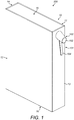
- FIG. 1 illustrates an embodiment of the present invention in which a beverage dispensing module 500 is operable to stand on a surface independently and is generally Bibliomorphic (book shaped).
- the module 500 comprises a container 10 having first and second major side walls 11, 12, first and second minor side walls 13, 14 and first and second end walls 15, 16.
- the term "minor” is used to indicate a small dimension (e.g. area or length) and the term “major” is used to indicate a larger dimension.
- the surface area of each of the first and second major side walls 11, 12 is larger than the surface area of each of the first and second minor side walls 13, 14.
- the walls are each substantially rectangular in shape.
- Each major edge of the first and second major side walls 11, 12 is coincident with a major edge of the first or second minor side wall 13, 14.
- Each minor edge of the first and second major side walls 11, 12 is coincident with a major edge of the first and second end walls 15, 16.
- Each minor edge of the first and second minor side walls 13, 14 is coincident with a minor edge of the first and second end walls 15, 16.
- the container 10 therefore has a substantially rectangular cuboidal shape and is, in a particularly preferred arrangement, of a height, width and depth such as to provide an upright container which is both capable of being freestanding and is also relatively stable in that configuration.
- the container 10 has another suitable shape, such as a cube or square cuboid.
- the beverage dispensing module 500 further comprises a beverage dispensing arrangement 100.
- the beverage dispensing arrangement 100 comprises an outlet arrangement 101 for controlling liquid beverage flow or selectively dispensing liquid beverage from a beverage reservoir located within the container 10.
- the outlet arrangement 101 comprises an outlet nozzle 102 mounted to the outside of the container 10 and a beverage dispensing valve 103 located at least partially within the container 10.
- the beverage dispensing valve 103 is controlled by a dispensing actuator 104.
- the beverage dispensing arrangement 100 is discussed in more detail below.
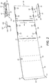
- the container 10 may be constructed in any suitable manner and several embodiments of the construction are illustrated in Figures 2 to 8 .
- the container 10 comprises a housing 30 forming the first and second minor and major side walls 11, 12, 13, 14.
- the housing 30 comprises substantially rectangular first, second, third and fourth minor and major housing panels 31, 32, 33, 34, 35, 36, 37, 38, top panel 39 and bottom panel 40.
- the first major housing panel 32 is attached along opposing major edges to major edges of the first and second minor housing panels 31, 33.
- the second major housing panel 34 is attached along opposing major edges to major edges of the second and third minor housing panels 33, 35.
- the third major housing panel 36 is attached along opposing major edges to major edges of the third and fourth minor housing panels 35, 37.
- the fourth major housing panel 38 is attached along a major edge to a major edge of the fourth minor housing panel 37.
- a major edge of each of the first minor housing panel 31 and fourth major housing panel 38 and all of the minor edges of the housing panels 31, 32, 33, 34, 35, 36, 37, 38 are free from other housing panels 31, 32, 33, 34, 35, 36, 37, 38.
- Each of the top and bottom panels 39, 40 comprise protrusions 41 around their periphery for mounting into apertures 42 in the housing panels 31, 32, 33, 34, 35, 36, 37, 38.
- two protrusions 41 are provided on each major edge of the top and bottom panels 39, 40 and corresponding mounting apertures 42 are provided adjacent the minor edges of the third and fourth major housing panels 36, 38.
- Apertures 43 are provided towards an upper end of the second and fourth minor housing panels 33, 37 for receiving the outlet arrangement 101.
- Components of the beverage dispensing arrangement 100 may be attached to the underside of the top panel 39, as will be described below.
- Slots 44 or the like may be provided along the third and fourth minor housing panels 35, 37 for receiving the ends of a roller of the beverage dispensing arrangement 100, as will also be described below.
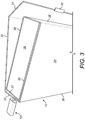
- the housing 30 may be folded along fold lines in between each of the housing panels 31, 32, 33, 34, 35, 36, 37, 38 such that the first and second minor housing panels 31, 33 form the second and first side walls 14, 13 respectively of the container 10 and the first and second major housing panels 32, 34 form the first and second major side walls 11, 12 respectively.
- the third and fourth minor and major housing panels 35, 36, 37, 38 are enclosed therein.
- the top and bottom panels 39, 40 are mounted adjacent the minor edges of the housing panels 31, 32, 33, 34, 35, 36, 37, 38 in the apertures 42, thereby forming the container 10 as an enclosure.
- Adhesive or other fixing means may be provided to hold the housing 30 in such an arrangement.
- a tab 45 may be provided for a user to easily break the adhesive or fixing means such that they can disassemble the housing 30, thereby enabling access to the parts of the container 10 for recycling or the like.
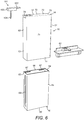
- the container 10 comprises a unitary housing 50 and top and bottom panels 51, 52.
- the housing 50 is formed from a relatively thin-walled tubular structure having a substantially rectangular cross-sectional shape when viewed from the top of the container 10 (i.e. in plan view).
- the housing 50 forms a substantially rectangular cuboid shape.
- the housing 50 comprises first and second major housing panels 53, 54 forming first and second major side walls 11, 12 respectively of the container 10 and connected at major edges to first and second minor housing panels 55, 56 forming first and second minor side walls 13, 14 of the container 10.
- components of the beverage dispensing arrangement 100 may be attached to the underside of the top panel 51, which forms the first end wall 15.
- the bottom panel 52 forms the second end wall 14. Slots (not shown) may be provided down the inside of the first and second minor housing panels 55, 56 for receiving and guiding a roller of the beverage dispensing arrangement 100.
- An enclosed container 10 is formed by attaching the top and bottom panels 51, 52 to the open ends of the housing 50, for example by adhesive and/or a press fit. In contrast to the first embodiment, the top and bottom panels 51, 52 may protrude from the housing 50 rather than be located inside it when the container 10 is assembled.
- the container 10 may comprise an inner housing 60, an outer housing 61 and a dispensing arrangement mount 62.
- Each of the inner and outer housings 60, 61 may be of a unitary structure and form a hollow, substantially rectangular cuboid shape.
- the inner housing 60 may comprise first and second minor inner housing panels 63, 64 connected at major edges to first and second major inner housing panels 65, 66.
- a bottom panel (not shown) is connected to the bottom minor edges of each of the inner housing panels 63, 64, 65, 66 and forms the second end wall 16 of the assembled container 10.
- Recesses or apertures 67 are provided in the first and second major inner housing panels 65, 66 for receiving the corresponding protrusions (not illustrated) on the dispensing arrangement mount 62. Slots 68 or the like may be provided along the first and second minor inner housing panels 63, 64 for receiving the ends of a roller of the beverage dispensing arrangement 100, as will also be described below.
- the outer housing 61 comprises first and second minor outer housing panels 69, 70, forming first and second minor side walls 13, 14 of the container 10, and connected at major edges to first and second major inner housing panels 71, 72, forming first and second major side walls 11, 12 respectively of the container 10.
- a top panel 73 is connected to the bottom minor edges of each of the inner housing panels 63, 64, 65, 66 and forms the first end wall 15 of the assembled container 10.
- An aperture 74 is provided adjacent the top end of the outer housing 61 for receiving the outlet arrangement 101.
- the outer housing 61 fits over the inner housing 60 and is attached thereto by a fixing means, such as an adhesive or the like.
- the dispensing arrangement mount 62 is mounted within the inner housing 60 and supports the beverage dispensing arrangement 100 therein.
- the container 10 comprises a rigid hoop or band 340 surrounding and defining an opening 341.
- the band opening 341 is closed laterally (i.e. on either side of the band 340) by first and second walls 342, 343 mounted inside the band 340, thereby forming a substantially sealed enclosure within.
- the first and second walls each comprise inturned panels for locating within the band 340.
- the outlet arrangement 101 is mounted to the band 340 and the first and second wall 342, 343.
- the first and second minor side walls 13, 14 and first and second end walls 15, 16 are formed by the band 340.
- the first and second major side walls 11, 12 are formed substantially from the outer edges of the band 340 and the first and second walls 342, 343.
- the band 340 comprises a strip having major internal and external surfaces 344, 345 formed substantially as a loop.
- the external surface 344 faces substantially away from the band 340 and the internal surface 345 faces towards itself or inwards from the band 340.
- the band 340 extends all the way around the periphery of the first and second walls 342, 343.
- the band 340 may also be described as a loop, ring, brace or hoop comprising a substantially continuous outer surface.
- the meaning of the term "substantially continuous” includes the embodiments wherein a split (described hereinbelow) is provided in the band.
- the band 340 may be substantially rectangular.
- the band 340 generally comprises at least one substantially flat outer surface to enable the container 10 to rest in a stable manner on a flat surface.
- the band 340 provides the primary structural support for the container 10.
- the band 340 prevents inwards collapse of the container 10 and thereby maintains the shape of the container 10 when a force is applied to the first and second minor side walls 13, 14 and first and second end walls 15, 16.
- the band 340 is stiffer than the first and second side walls 342, 343.
- the band 340 may be manufactured, for example, from a single cast of metal or from moulded plastic. Alternatively the band 340 is manufactured by bending an elongate plate or strip back on itself at four corners and joining the two ends of the plate together, for example by using a welding technique. The band 340 may alternatively be formed from a paper-based material, such as cardboard. A number of different arrangements may be employed to mount the first and second walls 342, 343 with the band 340, as illustrated in Figures 7 and 8 .
- the band 340 is split such that it may be extended in a flat configuration. This permits the width of the band 340 to be increased/expanded, in order to allow the first and second walls 342, 343 more readily to be separated from the band 340. This improves the ease of disassembly of the container 10.
- the band 340 may be completely continuous with no splits, as in the fifth embodiment of Figure 8 .
- the first and second walls 342, 343 each comprise mounting means 346 for receiving and supporting a dispensing arrangement mount 345 to which the beverage dispensing arrangement 100 is attached.
- Apertures 347, 348 are provided in the hoop 340 and first and second walls 342, 343 for receiving the outlet arrangement 101.
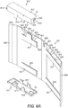
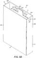
- the container 10 comprises a housing 601 forming the first and second minor and major side walls 11, 12, 13, 14.
- the housing 601 is illustrated in an assembled state in Figure 9B .
- the housing 601 comprises substantially rectangular first and second major housing panels 602, 603 and first, second and third 604, 605, 606 minor housing panels.
- a first major edge of the first minor housing panel 604 is attached to a first major edge of the first major housing panel 602 and the opposing second major edge of the first minor housing panel 604 is a free edge.
- the second major edge of the first major housing panel 602 is attached to a first major edge of the second minor housing panel 605.
- the second major edge of the second minor housing panel 605 is attached to a first major edge of the second major housing panel 603.
- the opposing second major edge of the second major housing panel 603 is attached to a first major edge of the third minor housing panel 606.
- the second major edge of the third minor housing panel 606 is a free edge.
- All of the housing panels 602, 603, 604, 605 other than the third minor housing panel 606 are formed of substantially rigid material, such as a stiff card.
- the third minor housing panel 606 is preferably formed of a relatively flexible material, although it may be formed from the same material as the other panels 602, 603, 604, 605.
- the third minor housing panel 606 comprises a tear strip 620 extending therealong between the first and second end walls 15, 16.
- the third minor housing panel 606 overlies the first minor housing panel 604 such that the first minor housing panel 604 is covered from the outside of the container 10.
- the third minor housing panel 606 is left unbonded to the first minor housing panel 604.
- the third minor housing panel 606 is bonded to the first minor housing panel 604 between the tear strip 620 and free second major edge of the third minor housing panel 606. Therefore, if the tear strip 620 is torn, the housing 601 is disassembled.
- the container 10 further comprises first and second end covers 610, 611.
- the first end cover 610 comprises a panel 612 attached to a dispensing arrangement mount 613.
- the dispensing arrangement mount 613 comprises four side walls 614 extending from the periphery of the panel 612.
- the side walls 614 comprise protrusions 615 extending therefrom.
- the second end cover 611 comprises a major panel 616 with protrusions 617 extending orthogonal to the plane of the major panel 616 from the periphery of the major panel 616.
- each of the protrusions 615, 617 are arranged to be mounted into internal recesses 625 formed on the inside of the major panels 602, 603 of the housing 601.
- the mounting of the protrusions 615, 617 and recesses 625 ensures that the end covers 610, 611 remain in place, but also prevents the major housing panels 602, 603 from bulging outwards when placed under force from the beverage reservoir therein.
- the recesses 625 may be formed as slots by multiple layers 626, 627 of panels.
- the first layer 626, adjacent to the major panels 602, 603, is shaped to comprise at least one indentation 628 and is substantially the same thickness as the protrusions 615, 617.
- the at least one indentation 628 comprises a shape corresponding to the protrusions 615, 617 such that the protrusions 615, 617 can be inserted therein.
- the second layer 627 is provided over the first layer 626 and overlies the indentation(s) 628, thereby forming the recesses 625.
- the second minor housing panel 605 and a side wall 614 of the dispensing arrangement mount 613 comprise corresponding apertures 630, 631 for receiving the outlet nozzle 102.
- the apertures 630, 631 are therefore formed substantially adjacent to an end of the container 10.
- the container 10 may be shaped and sized to fit through a domestic letterbox (mail slot).
- the opening in such a letterbox is typically around 250mm wide and around 30-40mm high, so the dimensions of a cross-section of the container 10 may be less than, say, 250mm x 40mm.
- the container 10 has the dimensions of about 200mm x 150mm x 36mm.
- the minor dimension of the first and second minor sides walls 13, 14 and first and second end walls 15, 16 is less than 40mm, more preferably less than 35mm and more preferably less than 30mm.
- Such dimensions equally permit delivery of the container 10 to a curbside mailbox such as is common in North America.
- the material selected to form the container 10 maintains the integrity of the reservoir when the container 10 is dropped through a letterbox onto the floor inside a building or onto the bottom of a mailbox.
- a letterbox onto the floor inside a building or onto the bottom of a mailbox.
- current standards permit the letterbox to be anywhere between 0.7m and 1.7m above the ground and the structure and integrity of the container 10 must be sufficient to accommodate this drop.
- the drop to the bottom of the mailbox from its opening is relatively short.
- the structural support provided by the cuboidal shape of the container 10 enables a plurality of modules 500 to be stacked adjacent to and/or on top of one another. Stacking efficiency is thereby achieved by the saving of space during stacking.
- the walls 11, 12, 13, 14, 15, 16 are preferably formed of a relatively rigid but deformable and lightweight material so as to provide, on the one hand, a degree of rigidity and impact protection to the container 10, but equally to allow manipulation (by hand or machine) so as to facilitate construction and dismantling of the container 10 as described below. It is further desirable that the walls 11, 12, 13, 14, 15, 16 are formed of a material or materials that is/are insoluble in water, and preferably liquid absorbent as well. The purpose of this is to avoid disintegration of the walls 11, 12, 13, 14, 15, 16 should the beverage inside the container 10 leak or be spilled upon the walls (internally or externally of them), or upon contact of a liquid, such as rain, with the outside of the container 10.
- a cardboard material is particularly preferred for reasons of cost, weight and ease of recycling, and because cardboard can be easily and inexpensively embossed and/or printed upon to allow identification and branding of the contents of the container 10.
- multi-ply cross-laminated duplex board has been found to provide suitable structural stiffness.
- the top and bottom panels 39, 40, 51, 52 and/or end covers 610, 611 are preferably formed of a plastics material since a user is most likely to use them to support the container 10 on a surface. By forming them of plastic, any residual liquid on the surface is not absorbed by the cardboard material forming the rest of the container 10 and the integrity of the container 10 is maintained.
- a cover layer for example a flexible laminate or paper layer, may also be provided around the walls 11, 12, 13, 14, 15, 16 to add further water resistance to the container 10.
- the cover layer may include logos and/or product information relating to the beverage inside the container 10.
- the walls 11, 12, 13, 14, 15, 16 need not necessarily be formed of a flexible material, again preferably a cardboard material may be employed even so, for reasons of cost, weight and so forth.
- a cardboard material may be employed even so, for reasons of cost, weight and so forth.
- FIG 10 illustrates an exploded view of the module 500 when constructed in a similar manner to the sixth embodiment shown in Figures 9A and 9B and including the beverage dispensing arrangement 100.
- the reference numerals referring to the features of the housing 601 and first and second end covers 610, 611 have been omitted for clarity, although the features are the same as described above.
- Figures 11 to 13 illustrate the components of the module 500 and beverage dispensing arrangement 100 in further detail.
- the beverage dispensing arrangement 100 generally comprises a pressurising arrangement 110 for applying pressure to a compressible beverage reservoir 111 containing a beverage.
- Compressing the reservoir 111 causes the beverage in turn to flow along the outlet arrangement 101, which comprises the outlet nozzle 102, the dispensing valve 103 and a dispensing conduit 106 formed between the body of the reservoir 111 and the outlet nozzle 102.
- the beverage presses against the dispensing valve 103 until opened by the dispensing actuator 104, when beverage is driven from the reservoir 111, along the dispensing conduit 106, through the dispensing valve 103 and out of the container 10 via the outlet nozzle 102.
- the reservoir 111 comprises a pouch 112 formed of a flexible membrane having an outlet 113 connected and sealed to the outlet arrangement 101.
- the construction of the pouch 112 will be described in more detail below.
- the pressurising arrangement 110 comprises a roller 114 and a resilient bias means 115 or mechanism. An end of the pouch 112 is attached along the length of the roller 114.
- the resilient bias means 115 is arranged to roll the roller 114 such that the internal volume of the pouch 112 is reduced by wrapping the pouch 112 around the roller 114 as beverage is dispensed from the pouch 112.
- the roller 114 is substantially elongate and extends from the first minor side wall 13 to the second minor side wall 14. As illustrated, the roller 114 has a circular cross-section and has the same diameter along its length. Such an arrangement is preferred in order to prevent the creation of air pockets within the pouch 112 and to ensure that the pouch 112 remains taught during dispensing. In alternative embodiments the roller 114 may have any other suitable cross-sectional shape, for example square, rectangular, hexagonal, triangular or octagonal. Furthermore, the diameter of the roller 114 may vary along its length, for example by being larger in the centre and decreasing towards the ends of the roller 114.
- the roller 114 may be shaped such that it has the smallest diameter where the pouch 112 has the greatest thickness, such that the overall thickness of the pouch 112 and roller 114, when the pouch 112 has been wrapped around the roller by several turns, is equal along the length of the pouch 112 and roller 114.
- the roller 114 may be formed from any suitable material, such as cardboard or a lightweight plastics material, and may be hollow (i.e. tubular) or substantially solid. Cardboard is preferred for sustainability reasons.
- the pouch 112 may be attached all the way along, or only partly along (for example, only at the sides of) the roller 114.
- the end of the pouch 112 opposite the outlet 113 i.e. the lower end in Figures 12 and 13
- only a central portion of the lower end of the pouch 112 may be attached to the roller 114.
- the resilient bias means 115 is attached to the roller 114 to resiliently bias the roller 114 by inducing a torque such that the roller 114 will rotate and apply a compressive force to the pouch 112 and any beverage inside it. Thus if no liquid pressure resists the compressive force the roller 114 will continue to rotate and the pouch 112 will wrap around it until it reaches the end of its range at the top of the container 10. In doing so, the internal volume within the pouch 112 will be reduced.
- the resilient bias means 115 comprises first and second springs 117, 118, each attached at either end of the roller 114.
- the springs 117, 118 are constant force roll springs and are formed of steel.
- the springs 117, 118 store mechanical energy such that they will apply a rotational force to the roller 114.
- the free end of each spring 117, 118 extends from the roller 114 to the top of the container 10 where it is attached to the container 10 by attachment means, such as one of the aforementioned dispensing mounts 39, 51, 62, 613, housings 30, 50, 60, 340, 601, first end cover 610, and/or walls 342, 343.
- each spring 117, 118 comprises an aperture 119 for attachment to hooking means (not shown), such as a peg or hook, on the inner side of the first end cover 610.
- the springs 117, 118 are wrapped around the roller 114.
- the springs 117, 118 may be attached to either end of the roller 114, for example by being mounted on pins protruding from the end faces of the roller 114.
- the free ends of the springs 117, 118 extend to the top of the container 10 between the pouch 112 and one of the major walls 11, 12 of the container 10.
- Such an arrangement is preferred as a relatively large pouch 112 may be included within the container 10.
- the pouch 112 does not overlap with the springs 117, 118 such that the springs 117, 118 are located between the pouch 112 and the first and second minor side walls 13, 14. Although such an arrangement may improve ease of assembly, for a fixed size of beverage container 10 the pouch 112 would need to be smaller and thus contain a smaller amount of beverage.
- the springs 117, 118 may be mounted on the roller 114 in recessed regions 120, having a smaller diameter than the rest of the roller 114, towards the ends of the roller 114.
- the recessed regions 120 may be formed integrally with the rest of the roller 114.
- the roller 114 may be formed from a first tube being inserted into the second tube of a larger internal diameter. The second tube is shorter than the first tube and is centrally positioned along the first tube, thereby exposing either end of the first tube. These exposed ends of the first tube form the recessed regions 120.
- springs 117, 118 there are various other suitable arrangements for the springs 117, 118. Only one or more than two springs 117, 118 may be attached between the roller 114 and the top of the container 10.
- the springs 117, 118 may be any other suitable type of spring, such as spiral or torsion springs. Furthermore, the springs need not be attached to the top of the container 10 and may instead only be attached to the roller 114.
- the resilient bias means 115 may alternatively comprise at least one elongate elastic (e.g. elastomeric) member attached to the roller 114 and arranged to induce a torque in the roller 114 such that it rotates.
- elongate elastic e.g. elastomeric
- Two suitable arrangements for the formation of the resilient bias means 115 by elastic members are shown in Figures 23A and 23B .
- the roller 114 is substantially hollow and the at least one elastic member 800 extends through it between the minor side walls 13, 14 of the container 10.
- the at least one elastic member 800 is anchored to the roller 114 towards its centre, as in Figure 23A .
- Two elastic members 800 are provided, each anchored in two apertures 801 spaced equally on either side of the centre of the elongate axis of rotation of the roller 114.
- Each end of the elastic members 800 is attached to the anchor members 802 at either end of the roller 114.
- the anchor members 802 are not rotatable, but can slide up and down the first and second minor side walls 13, 14 of the container 10.
- the anchor members 802 are square or rectangular (i.e.
- an interior anchor member 803 is provided within the roller 114.
- the interior anchor member 803 comprises a circular disc having an aperture 804 adjacent to its periphery for each elastic member 800 to pass through. It will be appreciated that in both of the embodiments of Figures 23A and 23B the two elastic members 800 could be joined at their ends to form elastic bands, or more than two elastic members 800 could be provided.
- At least one of the anchor members 802 is rotated to helically wind each elastic member 800 around itself as well as, if present, the other elastic member 800.
- the anchor members 802 are mounted in the slots 44, 68, the helical winding of the elastic member(s) will resiliently bias and induce a torque in the roller 114 such that it rotates and wraps the pouch 112 around it when beverage is dispensed from its internal volume.
- the anchoring of the elastic members 800 towards the centre of the roller 114 ensures that, during the unwinding of the elastic members 800, the roller 114 is maintained in a horizontal configuration. If it is not maintained in the horizontal configuration the roller 114 is prone to become jammed.
- the at least one elastic member 800 may be formed of polymer, latex, theraband, neoprene, silicone or the like. Preferably the at least one elastic member 800 is maintained within its elastic range between when the pouch 112 is full and when it is empty, such that it always provides a substantially equal compressive force to the pouch 112 over its range of expansion and contraction. It has been found that a circular cross section is particularly suitable for achieving such an effect as it comprises a relatively high number of cross-links in various directions which prevent stress relaxation. This is particularly the case when compared to an elastic member 800 having a substantially planar cross-section.
- first and second elastic members 800 may each be attached at either end of the roller 114 and extend to the top of the container 10.
- the tensile force of the at least one elastic member 800 may resiliently bias the roller 114 into rolling.
- the at least one elastic member 800 could, for example, be under maximum tension when the pouch 112 is full of beverage and may become progressively less taut as beverage is emptied.
- Figures 14 to 17 illustrate an embodiment of the pouch 112 of the present invention. It is noted that the dotted lines and cross-hatching are intended to be merely schematic representations of the areas where panels have been attached to other panels. This is particularly the case with Figure 17 , which is merely a schematic view of a blank 200 for forming the pouch 112 with the areas shown where the panels would be attached to one another in the assembled pouch 112.
- the pouch 112 is formed from a substantially flexible, impermeable, laminar membrane.
- the laminate is preferably of a type suitable for containing alcoholic beverage and thus withstands exposure to alcohol for a significantly long period of time and does not degrade or delaminate.
- the laminate also preferably has low fluid transmission rates to ensure that the composition of the beverage does not vary over the time, for example by preventing water and alcohol vapour escaping or allowing oxygen to enter.
- the laminate is arranged to be welded/sealed and the material is such that alcohol does no degrade the welds/seals. It is also preferred if the laminate does not degrade into the beverage such that the flavour of the beverage is changed during storage in the pouch 112.
- the laminate may comprise at least one metallised layer and at least one weld layer.
- the laminate may comprise a number of layers of PE (polyethylene), PET (polyethylene terephthalate), PETMET (PET metallised with a metal, such as aluminium, of negligible thickness), aluminium (referred to as ALU), EVOH (Ethylene vinyl alcohol), PP (polypropene), OPA (polyamide), silicon oxide and aluminium oxide.
- the pouch 112 comprises substantially opposing first and second major side panels 201, 202 and substantially opposing first and second minor side panels 203, 204.
- Each of the side panels 201, 202, 203, 204 comprises first and second major edges 205, 206, 207, 208, 209, 210, 211, 212, 245, 246 and first and second minor edges 213, 214, 215, 216, 217, 218, 219, 220.
- the side panels 201, 202, 203, 204 are attached to one another along the major edges 205, 206, 207, 208, 209, 210, 211, 212, 245, 246 at first, second, third and fourth corners 221, 222, 223, 224.
- the first major edge 205 of the first major side panel 201 is connected to the first major edge 209 the first minor side panel 203 along the first corner 221.
- the second major edge 210 of the first minor side panel 203 is connected to the first major edge 207 of the second major side panel 202 along the second corner 222.
- the second major edge 206 of the first major side panel 201 is connected to the first major edge 245 of the second minor side panel 204 along the third corner 223.
- the second major edges 208, 246 of the second major and minor side panels 202, 204 are connected along the fourth corner 224.
- the first minor edge 213 of the first major side panel 201 is attached to a first minor edge 215 of the second major side panel 202 and the second minor edge 214 of the first major side panel 201 is attached to a second minor edge 216 of the second major side panel 202.
- the pouch 112 further comprises first, second, third and fourth sealed regions 230, 231, 232, 233 (schematically represented by the dotted lines and cross-hatching) extending along and located adjacent to the first, second, third and fourth corners 221, 222, 223, 224 respectively.
- the first, second, third and fourth sealed sealed regions 230, 231, 232, 233 are formed as relatively stiff (i.e. stiffer than a single layer of the laminate) seals between the side panels 201, 202, 203, 204.
- Each of the first, second, third and fourth sealed regions 230, 231, 232, 233 extend away from the respective corner 221, 222, 223, 224 by a decreasing distance on either side of a central portion of the respective corner 221, 222, 223, 224.
- each of the sealed regions 230, 231, 232, 233 may extend from the respective corner 221, 222, 223, 224 in a substantially triangular shape, with the tip of the triangle being located in the central portion of the respective corner 221, 222, 223, 224.
- This profile has been found to be particularly effective in maintaining the pouch 112 in a suitable shape as it is rolled around the roller 114.
- the profile prevents the first and second major side panels 201, 202 from expanding significantly, when filled with beverage and pressurised, such that the pouch 112 interferes with the side walls 11, 12, 13, 14 of the container 10.
- the wider parts prevent such a large expansion.
- the narrower ends of the first, second, third and fourth sealed regions 230, 231, 232, 233 enable the pouch 112 to have a larger internal volume and thereby hold relatively more beverage.
- Each of the four corners 221, 222, 223, 224 extend from a first end 235 at the bottom of the pouch to a second end 236 at the top of the pouch 112.
- Each of the first, second, third and fourth sealed regions 230, 231, 232, 233 increasingly extend away from the respective corner 221, 222, 223, 224 towards the first end 235 such that these portions of each of the first, second, third and fourth sealed regions 230, 231, 232, 233 comprise a "K" or triangular profile at the first end 235, as is best illustrated in Figure 17 .
- the point of the triangle is coincident with each corner 221, 222, 223, 224.
- the first and third sealed regions 230, 232 start to increasingly extend away from the first and third corners 221, 223 towards the first end 235 closer to the first end 235 than the second and fourth sealed regions 231, 233 start to increasingly extend away from the second and fourth corners 222, 224 towards the first end 235.
- the triangular profile of the first and third sealed regions 230, 232 adjacent the first end 235 is smaller than the triangular profile of the second and fourth sealed regions 231, 233 adjacent the first end 235.
- the angle of the triangular profile of the first and third sealed regions 230, 232 is around 45° and the triangular profile of the second and fourth sealed regions 231, 233 is at an angle of less than 45° to the second and fourth corners 222, 224.
- This profile adjacent to the first end 235 has been found to assist in the start of the rolling of the pouch 112 around the roller 114.
- the first and second major side panels 201, 202 bulge outwards and over the roller 114 and these bulges may prevent the roller 114 from initially rotating.
- the second major side panel 202 By positioning the second major side panel 202 adjacent to the roller 114, the larger triangular profiles of the second and fourth sealed regions 231, 233 create a "lead-in" for the roller by raising the bulge above the roller 114. Therefore, the pressurising arrangement 110 will be able to initiate rolling of the roller 114 along the lead-in and thereby overcome the bulge in the first and second major side panels 201, 202.
- a first end sealed region 240 is provided between, and adjacent to the first minor edges 213, 215 of, the first and second major side panels 201, 202.
- the first end sealed region 240 extends between the first, second, third and fourth sealed regions 230, 231, 232, 233.
- An outlet portion 250 is provided at the second end 236 of the pouch 112.
- a second end sealed region 241 is provided between, and adjacent to the second minor edges 214, 216 of, the first and second major side panels 201, 202 and extends from the first and second sealed regions 230, 231.
- a third end sealed region 242 is also provided between the first major side panel 201 and second minor side panel 204 adjacent to the third sealed region 242.
- a fourth end sealed region 243 is also provided between the second major side panel 201 and second minor side panel 204 adjacent to the fourth sealed region 243.
- the outlet portion 250 further comprises an aperture 252, forming the pouch outlet 113, located between the second minor edges 214, 216 of the first and second major side panels 201, 202 and bounded by the second, third and fourth end sealed regions 241, 242, 243.
- the outlet portion 250 further comprises protruding portions 260, 261, 262 of the first and second major side panels 201, 202 and second minor side panel 204.
- each of the first and second major side panels 201, 202 and second minor side panel 204 comprise a substantially rectangular portion 263, 264, 265 and the protruding portions 260, 261, 262 extend from these rectangular portions 263, 264, 265 at the second end 236 of the pouch 112.
- the aperture 252 preferably extends from the protruding portions 260, 261 at an angle of 45° to the longitudinal axis between the first and second ends 235, 236.
- the outlet portion 250 is arranged to be connected to the outlet arrangement 101 of the beverage dispensing arrangement 100.
- An adapter 270 or the like may be sealed to the aperture 252 in order to provide the connection therebetween.
- the adaptor 270 may comprise a conduit entering the internal volume of the pouch 112 and connection means for connecting the conduit to the outlet arrangement 101.
- the adaptor 270 may be formed of the same material, but in a stiffened version, as the inner surface of the pouch 112 such that it can be welded thereto to form a water-tight seal.
- FIG. 14 to 17 a longitudinal seam 280 between free ends of the laminate is formed at the second sealed region 231.
- the longitudinal seam 280 may be formed at any other suitable location in the pouch 112.
- Figure 18 illustrates a further embodiment of a blank 290 for forming the pouch 112 of the present invention in which the longitudinal seam 291 is provided in the second major side panel 202.
- the second major side panel 202 is formed of first and second parts 292, 293 with free ends 294, 295.
- the free ends 294, 295 are sealed together, for example in a lap seal, in the assembled pouch 112.
- the pouch 112 may be formed from separate sheets of laminate, each forming one of the major and minor side panels 201, 202, 203, 204 and the seams therebetween are formed by the sealed regions 230, 231, 232, 233, 240, 241, 242, 243.
- the pouch 112 may comprise attachment means 300 for attaching the pouch 112 to the rest of the module 500.
- a plurality of apertures 301, 302, 303 may be provided at the second end 236 of the pouch 112 for connecting the pouch 112 to the container 10 via, for example, the aforementioned dispensing mounts 39, 51, 62, housings 30, 50, 60, 340 or walls 342, 343.
- One aperture 301 may be provided in the corner of the third and fourth sealed regions 242, 243 and two apertures 302, 303 may be provided through the second end sealed region 241.
- the sealed regions 230, 231, 232, 233, 240, 241, 242, 243 are preferably, as illustrated, fin seals.
- fin seal is known in the art and refers to a seal in which the laminate is attached onto itself on the same surface. This is in contrast to a "lap seal", in which the laminate is attached onto itself at an overlap such that opposing surfaces are attached to each other.
- the sealed regions 230, 231, 232, 233, 240, 241, 242, 243 may be lap seals.
- the sealed regions 230, 231, 232, 233, 240, 241, 242, 243 may be formed by heat sealing and/or welding the laminate together.
- the main body of the internal volume of the pouch 112 forms a generally rectangular cuboidal shape, predominantly due to the predominantly rectangular shape of the major and minor side panels 201, 202, 203, 204.
- the pouch 112 may not comprise a second minor side panel 204 and the first and second major side panels 201, 202 may be sealed together directly along their second major edges 206, 208.
- Figure 20 illustrates a further embodiment of the pouch 112 wherein it comprises an internal gusset 266 attached within the pouch 112 to each of the major side panels 201, 202.
- the internal gusset 266 is arranged to constrain the expansion of the areas of the major side panels 201, 202 adjacent to the internal gusset 266 to the width of the gusset 266.
- the gusset 266 comprises a constraining sheet 267 with a plurality of holes 268 for allowing beverage to pass through it.
- the gusset 266 may be formed in an "s" shape, or a "u" shape, with the edge regions welded or adhered to the inner surfaces of the major side panels 201, 202.
- the third and fourth sealed regions 242, 243 may be folded towards the adaptor 270.
- the outlet portion 250 remains open as the second minor side panel 204 provides a separation between the protruding portions 260, 261 through which beverage may pass.
- the outlet arrangement 101 comprises the outlet nozzle 102, an intermediary adapter 131, a valve arrangement 132 and a lever arrangement 133.
- the outlet nozzle 102 comprises an outlet aperture 130 at one end of an internal passageway 134 and an inlet aperture 135 and nozzle inlet adapter 136 at the opposing end of the internal passageway 134.
- the nozzle inlet adapter 136 comprises a hollow tube for mating to the intermediary adapter 131.
- the outlet nozzle 102 is mounted on and projects from the first minor side wall 13 and is generally offset from the centre line parallel to the minor edges of the first minor side wall 13. When the second end wall 16 stands on a surface, the outlet nozzle 102 is located in the upper half of the first minor side wall 13.
- the module 500 may be adapted such that the outlet nozzle 102 is on any of the other side walls 11, 12, 14.
- outlet nozzle 102 be positioned in the upper half of the side walls 11, 13, 12, 14, by locating the outlet nozzle 102 in that upper half, sufficient height is provided to allow a glass other drinks receptacle to be placed underneath the outlet nozzle 102 so that beverage can be dispensed directly into that drinks receptacle whilst it sits on a surface next to the container 10.
- the intermediary adapter 131 is sealed and connected at a first outer connector 137 to the nozzle inlet adapter 136 and at a second outer connector 138 to the pouch outlet 113.
- the first outer connector 137 may comprise a hollow tube which receives the hollow tube of the nozzle inlet adapter 136 and the second outer connector 138 may comprise a hollow tube inserted into connecting means of the pouch adaptor 270.
- the intermediary adapter 131 further comprises first and second inner connectors 139, 140, each in fluid communication with the first and second outer connectors 137, 138 respectively, in the form of hollow tubes extending towards one another.
- the intermediary adapter 131 also comprises a valve support wall 142 located underneath the valve arrangement 132, which will be described in further detail hereinbelow.
- the valve arrangement 132 comprises a tube 141 and the dispensing valve 103 is disposed therein.
- the dispensing valve 103 may be a one-way or check valve, which only opens when actuated by the dispensing actuator 104, and prevents the ingress of air into the reservoir 111 to prevent the beverage contained therein from deteriorating.
- the dispensing valve 103 is a duckbill valve 730 and the duckbill valve disclosed in UK Patent Application No. 1411147 , which is incorporated herein by reference, is particularly suitable.
- the tube 141 comprises a tube wall 712 forming an elongate passageway 713 having a first end 724 sealed to the first inner connector 139 and a second end 725 sealed to the second inner connector 140.
- the dispensing conduit 106 therefore leads from the pouch outlet 113 to, in order of fluid flow during dispensing, the second outer connector 138, the second inner connector 140, the passageway 713, the first inner connector 140, the nozzle inlet adapter 136, the internal passageway 134 and, finally, the outlet aperture 130.
- the dispensing valve 103 is formed of the duckbill valve 730, which comprises a mounting wall 731 attached to the inner surface of the tube wall 712.
- First and second valve walls 732, 733 extend from the mounting wall 731 at first ends 734, 735 to second ends 736, 737.
- the first and second valve walls 732, 733 are separated at their first ends 734, 735 by an opening 738 formed in the mounting wall 731.
- the opening 738 is substantially in the shape of a rectangle with two opposing curved edges. As illustrated, the opening 738 is arranged such that there is a portion of the mounting wall 731 between the tube wall 712 and opening 738 (i.e. the tube wall 712 and opening 738 are separated).
- the curved edges of the opening 738 may be formed by the tube wall 712 itself.
- the first and second valve walls 732, 733 converge towards each other from the opening 738 at their first ends 734, 735 and contact each other at their second ends 736, 737.
- the inner surfaces 744, 745 of the first and second valve walls 732, 733 are at an angle of less than 180° to one another and thereby define a V-shape.
- the second ends 736, 737 define between valve tips 739, 740 a valve mouth 741 which, when closed, is in the form of an elongate and straight slit.
- valve mouth 741 When closed the valve mouth 741 is elongate along the lateral axis such that it extends orthogonal to the longitudinal axis 714 along which the tube 141 extends.
- the valve mouth 741 is resiliently biased to be substantially in the closed position, although the valve mouth 741 will not be sealed in such a position until an external pressure is applied to the first and second valve walls 732, 733.
- the valve mouth 741 When opened the valve mouth 741 is in the shape of an oval or vesica piscis (i.e. oval shaped with pointed ends).
- first and second valve walls 732, 733 i.e. the edges in the transverse direction, are attached to the tube wall 712. Thus fluid can only pass through the valve mouth 741.
- the thicknesses of the first and second valve walls 732, 733 are substantially constant or reduce from the first ends 734, 735 to the second ends 736, 737.
- the tube 141 and duckbill valve 730 are formed from a resilient (i.e. elastomeric) material such that, after being squeezed or otherwise manipulated, it will return to the aforementioned shape in which the valve mouth 741 is closed.
- Suitable materials include elastomeric polymers, rubbers, butyl rubber, silicone and thermoplastic elastomers. For example, if fluid of a relatively high pressure enters the tube 141 at the first end 724 it will open the valve mouth 741 provided that the fluid on the second end 725 of the tube 141 has a lower pressure.
- valve mouth 741 will return to the closed position, although will not be sealed until the pressure at the first end 724 of the tube 141 is greater than the pressure at the second end 725 of the tube 141.
- valve mouth 741 is openable by squeezing the outside of the tube 141 using the dispensing actuator 104.
- the dispensing actuator 104 is operable to apply a compressive force along the lateral direction (i.e. in the plane along which the valve mouth 741 extends when closed) to open the valve mouth 741. This is a result of the elastic deformation of the first and second valve walls 732, 733 urging the valve tips 739, 740 away from each other to compensate for the reduced lateral dimension of the duckbill valve 730.
- the dispensing actuator 104 comprises the lever arrangement 133 and a dispensing lever 107 connected to the lever arrangement 133.
- the dispensing lever 107 is provided outside of the container 10 for a user to actuate, whilst the lever arrangement 133 is provided within the container 10 for translating the actuation of the dispensing lever 107 into the opening of the dispensing valve 103.
- the lever arrangement 133 comprises a substantially rectangular, ringshaped, main body 145 extending from adjacent to the outlet nozzle 102 towards a pivot arm 146 substantially adjacent to the second inner and outer connectors 138, 140.
- the pivot arm 146 extends from the main body 145 upwards and around the intermediary adapter 131 and valve arrangement 132 from one side of the ring of the main body 145 to the opposing side.
- the pivot arm 146 is attached to the container 10 such that it is pivotable about a pivot axis 147.
- a rod (not shown) may extend through a passageway in the pivot arm 146 and be inserted at either end into apertures in the first end cover 610.
- the lever arrangement 133 further comprises a valve arm 148 extending from one side of the ring of the main body 145 to the opposing side and disposed over the dispensing valve 103, particularly the valve mouth 741, within the valve arrangement 132.
- the valve support wall 142 is provided on the opposite side of the valve arrangement 132 to the valve arm 148.
- the dispensing lever 107 is mounted to the main body 145 by being inserted into a slot 149 in the main body 145 adjacent to the outlet nozzle 102.
- the valve arm 148 is located towards the dispensing lever 107 from the pivot arm 146.
- the pressurising arrangement 110 pressurises the beverage against the dispensing valve 103 when it is closed.
- the dispensing actuator 104 is operable to dispense beverage from the valve mouth 741 such that the overpressure causes beverage to be ejected from the opening.
- the main body 145 and valve arm 148 move downwards such that the lever arrangement 133 pivots about the pivot axis 147.
- the valve arm 148 also thereby moves downwards and compresses the dispensing valve 103 against the valve support wall 142 such that the valve mouth 741 opens.
- the intermediary adapter 131, lever arrangement 133 and valve arrangement 132 are connected to one another and attached to the first end cover 610.
- the roller 114 and resilient bias means 115 are subsequently attached to one another and mounted to the first end cover 610.
- the roller 114 and resilient bias means 115 are placed in a rig to extend the roller 114 to its fully extended position.
- the pouch 112 is filled with beverage and attached to the roller 114 at its lower end and to the first end cover 610 and its upper end.
- the container 10 is then constructed and mounted with the first end cover 610, for example by wrapping the housing 601 around the pouch 112, adhering the third minor housing panel 606 to the first minor housing panel 604, and then moving the housing 601 upwards such that the protrusions 615 mount within the recesses 625.
- the second end cover 611 is then mounted to the bottom of the housing 601 by fitting the protrusions 617 into the recesses 625.
- the outlet nozzle 102 is attached to the lever arrangement and intermediary adapter 131 through the apertures 630, 631.
- An initial seal may be provided in the outlet arrangement 101 for preventing fluid communication between the internal volume and atmosphere.
- the initial seal may comprise a foil over the outlet 130 of the outlet nozzle 102.
- the resilient bias means 115 applies an overpressure relative to atmosphere to the beverage within the pouch 112 by applying a torque to the roller 114.
- the beverage extends from the internal volume of the pouch 112 (i.e. from between the side panels 201, 202, 203, 204), through the dispensing conduit 106 and to the dispensing valve 103.
- the dispensing valve 103 and/or dispensing conduit 106 may be attached to the adapter 270 of the pouch 112.
- the dispensing valve 103 is arranged to prevent beverage flow unless the dispensing actuator 104 is actuated and opens the dispensing valve 103.
- the user may remove the initial seal from the outlet arrangement 101.
- the user actuates the dispensing actuator 104, for example by pressing down on a lever as illustrated in Figure 1 .
- the dispensing actuator 104 is arranged to provide a compressive force against the duckbill valve such that the valve mouth opens.
- the dispensing actuator is arranged to provide a compressive force directly in line with the valve tips and mouth such that the valve tips move apart. Beverage subsequently flows out of the dispensing valve 103 and out of an opening in the outlet arrangement 101.
- the pressurising arrangement 110 rotates the roller 114 such that pouch 112 wraps around it. Therefore, the internal volume is reduced and an overpressure is maintained in the beverage relative to atmosphere.
- the dispensing actuator 104 is released, the dispensing valve 103 closes and beverage no longer flows out of the pouch 112. The beverage applies an opposing force against the torque provided by the resilient bias means 115 such that the roller 114 no longer rotates.
- dispense events may be required until substantially all of the beverage has been dispensed from the module 500.
- the roller 114 When the internal volume is substantially empty the roller 114 will be located towards the outlet end of the container 10 and the pouch 112 will almost entirely be wrapped around the roller 114. A user may subsequently disassemble the module 500 and the parts may be recycled.
Description
- This invention is directed towards a beverage dispensing module and flexible pouch for such a beverage dispensing module. The beverage dispensing module is particularly suitable for alcoholic beverages.
- Beverages, for example alcoholic beverages, sodas, concentrates and the like, are commonly supplied individually to consumers in bottles and typically glass bottles. However, glass bottles utilise space inefficiently when stacked, are relatively heavy and can be broken relatively easily when subjected to an impact. Therefore, they are not optimally suited to transportation. Furthermore, when a bottle is opened air is able to contact the beverage, which may result in the evaporation of the beverage and/or causing the beverage to degrade. For example, the alcohol in an alcoholic beverage will evaporate, thereby reducing the alcoholic content of the beverage. The air may also oxidise the alcohol such that the taste of the beverage changes.
- Bag-in-box type containers commonly prevent air from contacting the beverage by comprising a one-way valve which allows beverage to flow out of, but prevents air from flowing into, the bag. However, such bag-in-box containers are not considered to be premium products by consumers and have, as a result, not replaced glass bottles as the typical beverage container. The bag-in-box type containers are also commonly very large (e.g. 3 to 5 litres) and are not suited to storing beverages, such as liquors, which are commonly supplied only in relatively smaller quantities (e.g. 1 litre). The box is also typically formed of cardboard or the like and thus has a relatively low structural strength. Therefore, they are not suited to vertical stacking in large numbers.
-
US1710658 discloses a device for dispensing the contents of collapsible tubes and particularly a device by means of which shaving cream, tooth paste or the like may be ejected from collapsible containers or tubes in the desired amounts. -
FR-A-2887458 -
US-A-4850971 discloses an infusion pump utilizing a linear roller driven by a one or more constant force springs in combination with changeable flow regulating needles to provide a constant flow, gravity independent device. The spring constant is chosen so that infusion substantially decreases should the infusion needle become dislodged from the vein and come to rest in the surrounding tissue. -
US-A-4765512 discloses a spring construction adopted for a dispensing system for fluent materials from a plastic or equivalent thin film bag. The spring construction is rolled up inside a coiling spiral formed from a strip sheet constant force spring material to squeeze out the bag contents and to produce dispensing force during storage periods for bulk quantities. - The present invention is directed in one aspect towards a beverage dispensing module according to claim 1.
- In a preferred embodiment of the present disclosure a container to which a beverage dispensing arrangement is attached comprises a housing and first and second end covers. The housing comprises first and second major and minor side walls and, at either end thereof, forms an opening for receiving the first and second end covers. The first and second end covers comprise at least one protrusion for mounting into recesses formed in, or adjacent to, the inner face of at least one of the side walls. The engagement between the protrusions and recesses holds the end covers in place. In a further embodiment the second minor side wall is formed from two minor side panels of the housing. A tear strip is provided from the first to second end of the outer minor side panel and the two minor side panels are adhered to one another such that when the tear strip is removed the two minor side panels are disconnected. Therefore, the housing can be unwrapped and easily recycled.
- The beverage dispensing module is suitable for containing alcoholic beverages and is particularly suitable for containing spirits, such as whisky, vodka, gin, liqueur, coffee liqueur, rum, aniseed-based spirit, pastis, cognac, brandy or tequila. The beverage dispensing module may also be suitable for containing other alcoholic beverages including champagne, wine, beer or cocktails, and/or other types of beverage, including sodas (also known as soft drinks) and beverage concentrates.
- By way of example only, embodiments of the present invention are now described with reference to, and as show in, the accompanying drawings, in which:
-
Figure 1 is a perspective view of an exemplary beverage dispensing module of the present invention; -
Figure 2 is a exploded view of a first embodiment of the construction of the beverage dispensing module of the present invention; -
Figure 3 is a perspective view illustrating a step in the assembly of the embodiment ofFigure 2 ; -
Figure 4 is a perspective view illustrating the embodiment ofFigure 2 when assembled; -
Figure 5 is an exploded perspective view of a second embodiment of the construction of the beverage dispensing module of the present invention; -
Figure 6 is an exploded perspective view of a third embodiment of the construction of the beverage dispensing module of the present invention; -
Figure 7 is an exploded perspective view of a fourth embodiment of the construction of the beverage dispensing module of the present invention; -
Figure 8 is an exploded perspective view of a fifth embodiment of the construction of the beverage dispensing module of the present invention; -
Figure 9A is an exploded perspective view of a sixth embodiment of the construction of the beverage dispensing module of the present invention; -
Figure 9B is a perspective view of a housing of the embodiment ofFigure 9A when assembled; -
Figure 10 is an exploded perspective view of an embodiment of the beverage dispensing module of the present invention including a beverage reservoir and beverage dispensing arrangement; -
Figure 11 is a perspective cross-sectional view of the module ofFigure 10 when assembled and with the beverage reservoir not shown; -
Figure 12 is a side elevation of the module ofFigure 10 when assembled wherein a side wall is not shown to illustrate the arrangement of the beverage reservoir and beverage dispensing arrangement; -
Figure 13 is a front elevation of the module ofFigure 10 wherein the front side wall is not shown; -
Figure 14 is a perspective view of a pouch of the beverage dispensing module of the present disclosure; -
Figure 15 is a side elevation of the pouch ofFigure 14 ; -
Figure 16 is a further side elevation of the pouch ofFigure 14 ; -
Figure 17 is a schematic of a blank for forming the pouch ofFigure 14 ; -
Figure 18 is a schematic of a blank for forming a further embodiment of a pouch of the beverage dispensing module of the present disclosure; -
Figure 19 is a side elevation of a second end of an embodiment of a pouch of the present disclosure including attachment means; -
Figure 20 is a partially hidden perspective view of a further embodiment of the pouch of the present disclosure illustrating a gusset provided inside the pouch; -
Figure 21A is a perspective view of an outlet arrangement of the module ofFigure 10 ; -
Figure 21B is an enlarged view ofFigure 11 illustrating the components of the outlet arrangement in further detail; -
Figures 22A and 22B are a cross-sectional side elevation and perspective view of a valve arrangement of the module ofFigure 10 ; and -
Figures 23A and 23B are schematics of embodiments of a pressuring arrangement of the present invention comprising elastic members mounted to a roller. -
Figure 1 illustrates an embodiment of the present invention in which abeverage dispensing module 500 is operable to stand on a surface independently and is generally bibliomorphic (book shaped). Themodule 500 comprises acontainer 10 having first and secondmajor side walls minor side walls second end walls major side walls minor side walls - As illustrated in
Figure 1 the walls are each substantially rectangular in shape. Each major edge of the first and secondmajor side walls minor side wall major side walls second end walls minor side walls second end walls container 10 therefore has a substantially rectangular cuboidal shape and is, in a particularly preferred arrangement, of a height, width and depth such as to provide an upright container which is both capable of being freestanding and is also relatively stable in that configuration. In alternative embodiments thecontainer 10 has another suitable shape, such as a cube or square cuboid. - The
beverage dispensing module 500 further comprises abeverage dispensing arrangement 100. Thebeverage dispensing arrangement 100 comprises anoutlet arrangement 101 for controlling liquid beverage flow or selectively dispensing liquid beverage from a beverage reservoir located within thecontainer 10. Theoutlet arrangement 101 comprises anoutlet nozzle 102 mounted to the outside of thecontainer 10 and abeverage dispensing valve 103 located at least partially within thecontainer 10. Thebeverage dispensing valve 103 is controlled by a dispensingactuator 104. Thebeverage dispensing arrangement 100 is discussed in more detail below. - The
container 10 may be constructed in any suitable manner and several embodiments of the construction are illustrated inFigures 2 to 8 . - In the first embodiment, as illustrated in
Figures 2 to 4 , thecontainer 10 comprises ahousing 30 forming the first and second minor andmajor side walls housing 30 comprises substantially rectangular first, second, third and fourth minor andmajor housing panels top panel 39 andbottom panel 40. The firstmajor housing panel 32 is attached along opposing major edges to major edges of the first and secondminor housing panels major housing panel 34 is attached along opposing major edges to major edges of the second and thirdminor housing panels major housing panel 36 is attached along opposing major edges to major edges of the third and fourthminor housing panels major housing panel 38 is attached along a major edge to a major edge of the fourthminor housing panel 37. A major edge of each of the firstminor housing panel 31 and fourthmajor housing panel 38 and all of the minor edges of thehousing panels other housing panels - Each of the top and
bottom panels protrusions 41 around their periphery for mounting intoapertures 42 in thehousing panels protrusions 41 are provided on each major edge of the top andbottom panels apertures 42 are provided adjacent the minor edges of the third and fourthmajor housing panels Apertures 43 are provided towards an upper end of the second and fourthminor housing panels outlet arrangement 101. Components of thebeverage dispensing arrangement 100 may be attached to the underside of thetop panel 39, as will be described below.Slots 44 or the like may be provided along the third and fourthminor housing panels beverage dispensing arrangement 100, as will also be described below. - During assembly the
housing 30 may be folded along fold lines in between each of thehousing panels minor housing panels first side walls container 10 and the first and secondmajor housing panels major side walls major housing panels bottom panels housing panels apertures 42, thereby forming thecontainer 10 as an enclosure. Adhesive or other fixing means may be provided to hold thehousing 30 in such an arrangement. Atab 45 may be provided for a user to easily break the adhesive or fixing means such that they can disassemble thehousing 30, thereby enabling access to the parts of thecontainer 10 for recycling or the like. - In the second embodiment, as illustrated in
Figure 5 , thecontainer 10 comprises aunitary housing 50 and top andbottom panels housing 50 is formed from a relatively thin-walled tubular structure having a substantially rectangular cross-sectional shape when viewed from the top of the container 10 (i.e. in plan view). Thus thehousing 50 forms a substantially rectangular cuboid shape. Thehousing 50 comprises first and secondmajor housing panels major side walls container 10 and connected at major edges to first and secondminor housing panels minor side walls container 10. In a similar manner to the first embodiment, components of thebeverage dispensing arrangement 100 may be attached to the underside of thetop panel 51, which forms thefirst end wall 15. Thebottom panel 52 forms thesecond end wall 14. Slots (not shown) may be provided down the inside of the first and secondminor housing panels beverage dispensing arrangement 100. Anenclosed container 10 is formed by attaching the top andbottom panels housing 50, for example by adhesive and/or a press fit. In contrast to the first embodiment, the top andbottom panels housing 50 rather than be located inside it when thecontainer 10 is assembled. - In a third embodiment, as illustrated in
Figure 6 , thecontainer 10 may comprise aninner housing 60, anouter housing 61 and a dispensingarrangement mount 62. Each of the inner andouter housings inner housing 60 may comprise first and second minorinner housing panels inner housing panels inner housing panels second end wall 16 of the assembledcontainer 10. Recesses orapertures 67 are provided in the first and second majorinner housing panels arrangement mount 62.Slots 68 or the like may be provided along the first and second minorinner housing panels beverage dispensing arrangement 100, as will also be described below. - The
outer housing 61 comprises first and second minorouter housing panels minor side walls container 10, and connected at major edges to first and second majorinner housing panels major side walls container 10. Atop panel 73 is connected to the bottom minor edges of each of theinner housing panels first end wall 15 of the assembledcontainer 10. Anaperture 74 is provided adjacent the top end of theouter housing 61 for receiving theoutlet arrangement 101. When assembled, theouter housing 61 fits over theinner housing 60 and is attached thereto by a fixing means, such as an adhesive or the like. The dispensingarrangement mount 62 is mounted within theinner housing 60 and supports thebeverage dispensing arrangement 100 therein. - In fourth and fifth embodiments, as illustrated in
Figures 7 and8 , thecontainer 10 comprises a rigid hoop orband 340 surrounding and defining anopening 341. Theband opening 341 is closed laterally (i.e. on either side of the band 340) by first andsecond walls band 340, thereby forming a substantially sealed enclosure within. The first and second walls each comprise inturned panels for locating within theband 340. Theoutlet arrangement 101 is mounted to theband 340 and the first andsecond wall minor side walls second end walls band 340. The first and secondmajor side walls band 340 and the first andsecond walls - The
band 340 comprises a strip having major internal andexternal surfaces external surface 344 faces substantially away from theband 340 and theinternal surface 345 faces towards itself or inwards from theband 340. Theband 340 extends all the way around the periphery of the first andsecond walls band 340 may also be described as a loop, ring, brace or hoop comprising a substantially continuous outer surface. The meaning of the term "substantially continuous" includes the embodiments wherein a split (described hereinbelow) is provided in the band. - As illustrated in
Figure 8 , theband 340 may be substantially rectangular. Theband 340 generally comprises at least one substantially flat outer surface to enable thecontainer 10 to rest in a stable manner on a flat surface. Theband 340 provides the primary structural support for thecontainer 10. Theband 340 prevents inwards collapse of thecontainer 10 and thereby maintains the shape of thecontainer 10 when a force is applied to the first and secondminor side walls second end walls band 340 is stiffer than the first andsecond side walls - The
band 340 may be manufactured, for example, from a single cast of metal or from moulded plastic. Alternatively theband 340 is manufactured by bending an elongate plate or strip back on itself at four corners and joining the two ends of the plate together, for example by using a welding technique. Theband 340 may alternatively be formed from a paper-based material, such as cardboard. A number of different arrangements may be employed to mount the first andsecond walls band 340, as illustrated inFigures 7 and8 . - In the fourth embodiment of
Figure 7 , theband 340 is split such that it may be extended in a flat configuration. This permits the width of theband 340 to be increased/expanded, in order to allow the first andsecond walls band 340. This improves the ease of disassembly of thecontainer 10. Alternatively, theband 340 may be completely continuous with no splits, as in the fifth embodiment ofFigure 8 . - The first and
second walls means 346 for receiving and supporting a dispensingarrangement mount 345 to which thebeverage dispensing arrangement 100 is attached.Apertures hoop 340 and first andsecond walls outlet arrangement 101. - In a sixth, preferred, embodiment, as illustrated in
Figures 9A and9B , the thecontainer 10 comprises ahousing 601 forming the first and second minor andmajor side walls housing 601 is illustrated in an assembled state inFigure 9B . Thehousing 601 comprises substantially rectangular first and secondmajor housing panels minor housing panel 604 is attached to a first major edge of the firstmajor housing panel 602 and the opposing second major edge of the firstminor housing panel 604 is a free edge. The second major edge of the firstmajor housing panel 602 is attached to a first major edge of the secondminor housing panel 605. The second major edge of the secondminor housing panel 605 is attached to a first major edge of the secondmajor housing panel 603. The opposing second major edge of the secondmajor housing panel 603 is attached to a first major edge of the thirdminor housing panel 606. The second major edge of the thirdminor housing panel 606 is a free edge. - All of the
housing panels minor housing panel 606 are formed of substantially rigid material, such as a stiff card. The thirdminor housing panel 606 is preferably formed of a relatively flexible material, although it may be formed from the same material as theother panels - The third
minor housing panel 606 comprises atear strip 620 extending therealong between the first andsecond end walls housing 601 is assembled, the thirdminor housing panel 606 overlies the firstminor housing panel 604 such that the firstminor housing panel 604 is covered from the outside of thecontainer 10. Between thetear strip 620 and first major edge of the thirdminor housing panel 606 the thirdminor housing panel 606 is left unbonded to the firstminor housing panel 604. However, the thirdminor housing panel 606 is bonded to the firstminor housing panel 604 between thetear strip 620 and free second major edge of the thirdminor housing panel 606. Therefore, if thetear strip 620 is torn, thehousing 601 is disassembled. - The
container 10 further comprises first and second end covers 610, 611. Thefirst end cover 610 comprises apanel 612 attached to a dispensingarrangement mount 613. The dispensingarrangement mount 613 comprises fourside walls 614 extending from the periphery of thepanel 612. Theside walls 614 compriseprotrusions 615 extending therefrom. Thesecond end cover 611 comprises amajor panel 616 withprotrusions 617 extending orthogonal to the plane of themajor panel 616 from the periphery of themajor panel 616. - Each of the
protrusions internal recesses 625 formed on the inside of themajor panels housing 601. The mounting of theprotrusions major housing panels Figure 9A , therecesses 625 may be formed as slots bymultiple layers first layer 626, adjacent to themajor panels indentation 628 and is substantially the same thickness as theprotrusions indentation 628 comprises a shape corresponding to theprotrusions protrusions second layer 627 is provided over thefirst layer 626 and overlies the indentation(s) 628, thereby forming therecesses 625. - The second
minor housing panel 605 and aside wall 614 of the dispensingarrangement mount 613 comprise correspondingapertures outlet nozzle 102. Theapertures container 10. - The
container 10 may be shaped and sized to fit through a domestic letterbox (mail slot). In Europe, the opening in such a letterbox is typically around 250mm wide and around 30-40mm high, so the dimensions of a cross-section of thecontainer 10 may be less than, say, 250mm x 40mm. In a particular embodiment, thecontainer 10 has the dimensions of about 200mm x 150mm x 36mm. Preferably the minor dimension of the first and secondminor sides walls second end walls container 10 to a curbside mailbox such as is common in North America. - The material selected to form the
container 10 maintains the integrity of the reservoir when thecontainer 10 is dropped through a letterbox onto the floor inside a building or onto the bottom of a mailbox. Again, in Europe, current standards permit the letterbox to be anywhere between 0.7m and 1.7m above the ground and the structure and integrity of thecontainer 10 must be sufficient to accommodate this drop. Of course, where a mailbox is provided instead of an opening in a door of a dwelling, for example, the drop to the bottom of the mailbox from its opening is relatively short. - The structural support provided by the cuboidal shape of the
container 10 enables a plurality ofmodules 500 to be stacked adjacent to and/or on top of one another. Stacking efficiency is thereby achieved by the saving of space during stacking. - In the embodiments the
walls container 10, but equally to allow manipulation (by hand or machine) so as to facilitate construction and dismantling of thecontainer 10 as described below. It is further desirable that thewalls walls container 10 leak or be spilled upon the walls (internally or externally of them), or upon contact of a liquid, such as rain, with the outside of thecontainer 10. - A cardboard material is particularly preferred for reasons of cost, weight and ease of recycling, and because cardboard can be easily and inexpensively embossed and/or printed upon to allow identification and branding of the contents of the
container 10. In particular, multi-ply cross-laminated duplex board has been found to provide suitable structural stiffness. If included, the top andbottom panels container 10 on a surface. By forming them of plastic, any residual liquid on the surface is not absorbed by the cardboard material forming the rest of thecontainer 10 and the integrity of thecontainer 10 is maintained. - A cover layer, for example a flexible laminate or paper layer, may also be provided around the
walls container 10. In addition, the cover layer may include logos and/or product information relating to the beverage inside thecontainer 10. - Although, again as noted, the
walls container 10, it is to be that these are merely exemplary and that other forms are contemplated. In particular, in terms of sustainability of materials, ease of recycling, cost, weight and so forth, it is not essential that thecontainer 10 be formed of multiple separate or separable parts. -
Figure 10 illustrates an exploded view of themodule 500 when constructed in a similar manner to the sixth embodiment shown inFigures 9A and9B and including thebeverage dispensing arrangement 100. InFigure 10 the reference numerals referring to the features of thehousing 601 and first and second end covers 610, 611 have been omitted for clarity, although the features are the same as described above.Figures 11 to 13 illustrate the components of themodule 500 andbeverage dispensing arrangement 100 in further detail. Thebeverage dispensing arrangement 100 generally comprises a pressurisingarrangement 110 for applying pressure to acompressible beverage reservoir 111 containing a beverage. Compressing thereservoir 111 causes the beverage in turn to flow along theoutlet arrangement 101, which comprises theoutlet nozzle 102, the dispensingvalve 103 and a dispensingconduit 106 formed between the body of thereservoir 111 and theoutlet nozzle 102. The beverage presses against the dispensingvalve 103 until opened by the dispensingactuator 104, when beverage is driven from thereservoir 111, along the dispensingconduit 106, through the dispensingvalve 103 and out of thecontainer 10 via theoutlet nozzle 102. Preferably there are no air gaps within thereservoir 111, such that as beverage is ejected the internal volume of thereservoir 111 is reduced. - The
reservoir 111 comprises apouch 112 formed of a flexible membrane having anoutlet 113 connected and sealed to theoutlet arrangement 101. The construction of thepouch 112 will be described in more detail below. The pressurisingarrangement 110 comprises aroller 114 and a resilient bias means 115 or mechanism. An end of thepouch 112 is attached along the length of theroller 114. The resilient bias means 115 is arranged to roll theroller 114 such that the internal volume of thepouch 112 is reduced by wrapping thepouch 112 around theroller 114 as beverage is dispensed from thepouch 112. - The
roller 114 is substantially elongate and extends from the firstminor side wall 13 to the secondminor side wall 14. As illustrated, theroller 114 has a circular cross-section and has the same diameter along its length. Such an arrangement is preferred in order to prevent the creation of air pockets within thepouch 112 and to ensure that thepouch 112 remains taught during dispensing. In alternative embodiments theroller 114 may have any other suitable cross-sectional shape, for example square, rectangular, hexagonal, triangular or octagonal. Furthermore, the diameter of theroller 114 may vary along its length, for example by being larger in the centre and decreasing towards the ends of theroller 114. Theroller 114 may be shaped such that it has the smallest diameter where thepouch 112 has the greatest thickness, such that the overall thickness of thepouch 112 androller 114, when thepouch 112 has been wrapped around the roller by several turns, is equal along the length of thepouch 112 androller 114. - The
roller 114 may be formed from any suitable material, such as cardboard or a lightweight plastics material, and may be hollow (i.e. tubular) or substantially solid. Cardboard is preferred for sustainability reasons. - The
pouch 112 may be attached all the way along, or only partly along (for example, only at the sides of) theroller 114. In particular, the end of thepouch 112 opposite the outlet 113 (i.e. the lower end inFigures 12 and13 ) may be adhered along its length theroller 114. Alternatively, only a central portion of the lower end of thepouch 112 may be attached to theroller 114. - The resilient bias means 115 is attached to the
roller 114 to resiliently bias theroller 114 by inducing a torque such that theroller 114 will rotate and apply a compressive force to thepouch 112 and any beverage inside it. Thus if no liquid pressure resists the compressive force theroller 114 will continue to rotate and thepouch 112 will wrap around it until it reaches the end of its range at the top of thecontainer 10. In doing so, the internal volume within thepouch 112 will be reduced. - In the illustrated embodiments the resilient bias means 115 comprises first and
second springs roller 114. Preferably thesprings springs roller 114. The free end of eachspring roller 114 to the top of thecontainer 10 where it is attached to thecontainer 10 by attachment means, such as one of the aforementioned dispensing mounts 39, 51, 62, 613,housings first end cover 610, and/orwalls Figures 10 to 13 , eachspring aperture 119 for attachment to hooking means (not shown), such as a peg or hook, on the inner side of thefirst end cover 610. - In the illustrated embodiments the
springs roller 114. However, in alternative embodiments thesprings roller 114, for example by being mounted on pins protruding from the end faces of theroller 114. As best illustrated inFigure 13 , the free ends of thesprings container 10 between thepouch 112 and one of themajor walls container 10. Such an arrangement is preferred as a relativelylarge pouch 112 may be included within thecontainer 10. In an alternative arrangement thepouch 112 does not overlap with thesprings springs pouch 112 and the first and secondminor side walls beverage container 10 thepouch 112 would need to be smaller and thus contain a smaller amount of beverage. - The
springs roller 114 in recessedregions 120, having a smaller diameter than the rest of theroller 114, towards the ends of theroller 114. When theroller 114 reaches the top of its range and thepouch 112 has entirely wrapped around it, the provision of thesprings regions 120 has been found to ensure that there is less residual beverage left in thepouch 112. The recessedregions 120 may be formed integrally with the rest of theroller 114. Alternatively, theroller 114 may be formed from a first tube being inserted into the second tube of a larger internal diameter. The second tube is shorter than the first tube and is centrally positioned along the first tube, thereby exposing either end of the first tube. These exposed ends of the first tube form the recessedregions 120. - It will be appreciated that there are various other suitable arrangements for the
springs springs roller 114 and the top of thecontainer 10. Thesprings container 10 and may instead only be attached to theroller 114. - The resilient bias means 115 may alternatively comprise at least one elongate elastic (e.g. elastomeric) member attached to the
roller 114 and arranged to induce a torque in theroller 114 such that it rotates. Two suitable arrangements for the formation of the resilient bias means 115 by elastic members are shown inFigures 23A and 23B . As illustrated, preferably theroller 114 is substantially hollow and the at least oneelastic member 800 extends through it between theminor side walls container 10. - Preferably the at least one
elastic member 800 is anchored to theroller 114 towards its centre, as inFigure 23A . Twoelastic members 800 are provided, each anchored in twoapertures 801 spaced equally on either side of the centre of the elongate axis of rotation of theroller 114. Each end of theelastic members 800 is attached to theanchor members 802 at either end of theroller 114. Theanchor members 802 are not rotatable, but can slide up and down the first and secondminor side walls container 10. For example, theanchor members 802 are square or rectangular (i.e. include two parallel edges) and are mounted in theslots minor side walls major side walls Figure 23B , aninterior anchor member 803 is provided within theroller 114. Theinterior anchor member 803 comprises a circular disc having anaperture 804 adjacent to its periphery for eachelastic member 800 to pass through. It will be appreciated that in both of the embodiments ofFigures 23A and 23B the twoelastic members 800 could be joined at their ends to form elastic bands, or more than twoelastic members 800 could be provided. - During assembly at least one of the
anchor members 802 is rotated to helically wind eachelastic member 800 around itself as well as, if present, the otherelastic member 800. Once theanchor members 802 are mounted in theslots roller 114 such that it rotates and wraps thepouch 112 around it when beverage is dispensed from its internal volume. The anchoring of theelastic members 800 towards the centre of theroller 114 ensures that, during the unwinding of theelastic members 800, theroller 114 is maintained in a horizontal configuration. If it is not maintained in the horizontal configuration theroller 114 is prone to become jammed. - The at least one
elastic member 800 may be formed of polymer, latex, theraband, neoprene, silicone or the like. Preferably the at least oneelastic member 800 is maintained within its elastic range between when thepouch 112 is full and when it is empty, such that it always provides a substantially equal compressive force to thepouch 112 over its range of expansion and contraction. It has been found that a circular cross section is particularly suitable for achieving such an effect as it comprises a relatively high number of cross-links in various directions which prevent stress relaxation. This is particularly the case when compared to anelastic member 800 having a substantially planar cross-section. - In an alternative embodiment, first and second
elastic members 800 may each be attached at either end of theroller 114 and extend to the top of thecontainer 10. The tensile force of the at least oneelastic member 800 may resiliently bias theroller 114 into rolling. The at least oneelastic member 800 could, for example, be under maximum tension when thepouch 112 is full of beverage and may become progressively less taut as beverage is emptied. -
Figures 14 to 17 illustrate an embodiment of thepouch 112 of the present invention. It is noted that the dotted lines and cross-hatching are intended to be merely schematic representations of the areas where panels have been attached to other panels. This is particularly the case withFigure 17 , which is merely a schematic view of a blank 200 for forming thepouch 112 with the areas shown where the panels would be attached to one another in the assembledpouch 112. - The
pouch 112 is formed from a substantially flexible, impermeable, laminar membrane. The laminate is preferably of a type suitable for containing alcoholic beverage and thus withstands exposure to alcohol for a significantly long period of time and does not degrade or delaminate. The laminate also preferably has low fluid transmission rates to ensure that the composition of the beverage does not vary over the time, for example by preventing water and alcohol vapour escaping or allowing oxygen to enter. Further preferably, the laminate is arranged to be welded/sealed and the material is such that alcohol does no degrade the welds/seals. It is also preferred if the laminate does not degrade into the beverage such that the flavour of the beverage is changed during storage in thepouch 112. - The laminate may comprise at least one metallised layer and at least one weld layer. The laminate may comprise a number of layers of PE (polyethylene), PET (polyethylene terephthalate), PETMET (PET metallised with a metal, such as aluminium, of negligible thickness), aluminium (referred to as ALU), EVOH (Ethylene vinyl alcohol), PP (polypropene), OPA (polyamide), silicon oxide and aluminium oxide.
- The
pouch 112 comprises substantially opposing first and secondmajor side panels minor side panels side panels major edges minor edges side panels major edges fourth corners major edge 205 of the firstmajor side panel 201 is connected to the firstmajor edge 209 the firstminor side panel 203 along thefirst corner 221. The secondmajor edge 210 of the firstminor side panel 203 is connected to the firstmajor edge 207 of the secondmajor side panel 202 along thesecond corner 222. The secondmajor edge 206 of the firstmajor side panel 201 is connected to the firstmajor edge 245 of the secondminor side panel 204 along thethird corner 223. The secondmajor edges minor side panels fourth corner 224. The firstminor edge 213 of the firstmajor side panel 201 is attached to a firstminor edge 215 of the secondmajor side panel 202 and the secondminor edge 214 of the firstmajor side panel 201 is attached to a secondminor edge 216 of the secondmajor side panel 202. - The
pouch 112 further comprises first, second, third and fourth sealedregions fourth corners regions side panels regions respective corner respective corner minor edges side panels regions respective corner respective corner - This profile has been found to be particularly effective in maintaining the
pouch 112 in a suitable shape as it is rolled around theroller 114. In particular, the profile prevents the first and secondmajor side panels pouch 112 interferes with theside walls container 10. This is due to the first, second, third and fourth sealedregions side panels side panels pouch 112 is filled with beverage. The wider parts prevent such a large expansion. The narrower ends of the first, second, third and fourth sealedregions pouch 112 to have a larger internal volume and thereby hold relatively more beverage. - Each of the four
corners first end 235 at the bottom of the pouch to asecond end 236 at the top of thepouch 112. Each of the first, second, third and fourth sealedregions respective corner first end 235 such that these portions of each of the first, second, third and fourth sealedregions first end 235, as is best illustrated inFigure 17 . The point of the triangle is coincident with eachcorner - The first and third
sealed regions third corners first end 235 closer to thefirst end 235 than the second and fourth sealedregions fourth corners first end 235. Thus the triangular profile of the first and thirdsealed regions first end 235 is smaller than the triangular profile of the second and fourth sealedregions first end 235. In particular, the angle of the triangular profile of the first and thirdsealed regions regions fourth corners - This profile adjacent to the
first end 235 has been found to assist in the start of the rolling of thepouch 112 around theroller 114. When thepouch 112 is filled with beverage, the first and secondmajor side panels roller 114 and these bulges may prevent theroller 114 from initially rotating. By positioning the secondmajor side panel 202 adjacent to theroller 114, the larger triangular profiles of the second and fourth sealedregions roller 114. Therefore, the pressurisingarrangement 110 will be able to initiate rolling of theroller 114 along the lead-in and thereby overcome the bulge in the first and secondmajor side panels - A first end sealed
region 240 is provided between, and adjacent to the firstminor edges major side panels region 240 extends between the first, second, third and fourth sealedregions - An
outlet portion 250 is provided at thesecond end 236 of thepouch 112. A second end sealedregion 241 is provided between, and adjacent to the secondminor edges major side panels regions region 242 is also provided between the firstmajor side panel 201 and secondminor side panel 204 adjacent to the thirdsealed region 242. A fourth end sealedregion 243 is also provided between the secondmajor side panel 201 and secondminor side panel 204 adjacent to the fourth sealedregion 243. Theoutlet portion 250 further comprises anaperture 252, forming thepouch outlet 113, located between the secondminor edges major side panels regions - The
outlet portion 250 further comprises protrudingportions major side panels minor side panel 204. As best shown inFigure 17 , each of the first and secondmajor side panels minor side panel 204 comprise a substantiallyrectangular portion portions rectangular portions second end 236 of thepouch 112. Theaperture 252 preferably extends from the protrudingportions outlet portion 250 is arranged to be connected to theoutlet arrangement 101 of thebeverage dispensing arrangement 100. - An
adapter 270 or the like may be sealed to theaperture 252 in order to provide the connection therebetween. Theadaptor 270 may comprise a conduit entering the internal volume of thepouch 112 and connection means for connecting the conduit to theoutlet arrangement 101. Theadaptor 270 may be formed of the same material, but in a stiffened version, as the inner surface of thepouch 112 such that it can be welded thereto to form a water-tight seal. - In the embodiment of
Figures 14 to 17 alongitudinal seam 280 between free ends of the laminate is formed at the second sealedregion 231. However, thelongitudinal seam 280 may be formed at any other suitable location in thepouch 112.Figure 18 illustrates a further embodiment of a blank 290 for forming thepouch 112 of the present invention in which thelongitudinal seam 291 is provided in the secondmajor side panel 202. The secondmajor side panel 202 is formed of first andsecond parts free ends pouch 112. In yet further embodiments thepouch 112 may be formed from separate sheets of laminate, each forming one of the major andminor side panels regions - Furthermore, the
pouch 112 may comprise attachment means 300 for attaching thepouch 112 to the rest of themodule 500. In particular, as illustrated inFigure 19 , a plurality ofapertures second end 236 of thepouch 112 for connecting thepouch 112 to thecontainer 10 via, for example, the aforementioned dispensing mounts 39, 51, 62,housings walls aperture 301 may be provided in the corner of the third and fourth sealedregions apertures region 241. By supporting thepouch 112 at such positions, theoutlet portion 250 is maintained in an open position such that it cannot be creased shut. Furthermore, thepouch 112 remains sufficiently taught during wrapping around theroller 114 that it empties efficiently during beverage dispensing. - The sealed
regions regions regions - In the aforementioned embodiments the main body of the internal volume of the
pouch 112 forms a generally rectangular cuboidal shape, predominantly due to the predominantly rectangular shape of the major andminor side panels pouch 112 fall within the scope of the present disclosure. Furthermore, thepouch 112 may not comprise a secondminor side panel 204 and the first and secondmajor side panels major edges -
Figure 20 illustrates a further embodiment of thepouch 112 wherein it comprises aninternal gusset 266 attached within thepouch 112 to each of themajor side panels internal gusset 266 is arranged to constrain the expansion of the areas of themajor side panels internal gusset 266 to the width of thegusset 266. Thegusset 266 comprises a constrainingsheet 267 with a plurality ofholes 268 for allowing beverage to pass through it. Thegusset 266 may be formed in an "s" shape, or a "u" shape, with the edge regions welded or adhered to the inner surfaces of themajor side panels - Furthermore, when the
pouch 112 is assembled, the third and fourth sealedregions adaptor 270. As a result, theoutlet portion 250 remains open as the secondminor side panel 204 provides a separation between the protrudingportions - An embodiment of the
outlet arrangement 101 is illustrated in detail inFigures 10 ,11 ,12 and21A ,21B ,22A and 22B . Theoutlet arrangement 101 comprises theoutlet nozzle 102, anintermediary adapter 131, avalve arrangement 132 and alever arrangement 133. Theoutlet nozzle 102 comprises anoutlet aperture 130 at one end of aninternal passageway 134 and aninlet aperture 135 andnozzle inlet adapter 136 at the opposing end of theinternal passageway 134. Thenozzle inlet adapter 136 comprises a hollow tube for mating to theintermediary adapter 131. - The
outlet nozzle 102 is mounted on and projects from the firstminor side wall 13 and is generally offset from the centre line parallel to the minor edges of the firstminor side wall 13. When thesecond end wall 16 stands on a surface, theoutlet nozzle 102 is located in the upper half of the firstminor side wall 13. However, it will be appreciated that themodule 500 may be adapted such that theoutlet nozzle 102 is on any of theother side walls outlet nozzle 102 be positioned in the upper half of theside walls outlet nozzle 102 in that upper half, sufficient height is provided to allow a glass other drinks receptacle to be placed underneath theoutlet nozzle 102 so that beverage can be dispensed directly into that drinks receptacle whilst it sits on a surface next to thecontainer 10. - The
intermediary adapter 131 is sealed and connected at a firstouter connector 137 to thenozzle inlet adapter 136 and at a secondouter connector 138 to thepouch outlet 113. The firstouter connector 137 may comprise a hollow tube which receives the hollow tube of thenozzle inlet adapter 136 and the secondouter connector 138 may comprise a hollow tube inserted into connecting means of thepouch adaptor 270. Theintermediary adapter 131 further comprises first and secondinner connectors 139, 140, each in fluid communication with the first and secondouter connectors intermediary adapter 131 also comprises avalve support wall 142 located underneath thevalve arrangement 132, which will be described in further detail hereinbelow. - The
valve arrangement 132 comprises atube 141 and the dispensingvalve 103 is disposed therein. The dispensingvalve 103 may be a one-way or check valve, which only opens when actuated by the dispensingactuator 104, and prevents the ingress of air into thereservoir 111 to prevent the beverage contained therein from deteriorating. Preferably the dispensingvalve 103 is aduckbill valve 730 and the duckbill valve disclosed in UK Patent Application No.1411147 Figures 22A and 22B , thetube 141 comprises atube wall 712 forming anelongate passageway 713 having afirst end 724 sealed to the first inner connector 139 and asecond end 725 sealed to the secondinner connector 140. - The dispensing
conduit 106 therefore leads from thepouch outlet 113 to, in order of fluid flow during dispensing, the secondouter connector 138, the secondinner connector 140, thepassageway 713, the firstinner connector 140, thenozzle inlet adapter 136, theinternal passageway 134 and, finally, theoutlet aperture 130. - The dispensing
valve 103 is formed of theduckbill valve 730, which comprises a mountingwall 731 attached to the inner surface of thetube wall 712. First andsecond valve walls 732, 733 extend from the mountingwall 731 at first ends 734, 735 to second ends 736, 737. The first andsecond valve walls 732, 733 are separated at their first ends 734, 735 by anopening 738 formed in the mountingwall 731. Theopening 738 is substantially in the shape of a rectangle with two opposing curved edges. As illustrated, theopening 738 is arranged such that there is a portion of the mountingwall 731 between thetube wall 712 and opening 738 (i.e. thetube wall 712 andopening 738 are separated). However, in other embodiments the curved edges of theopening 738 may be formed by thetube wall 712 itself. - The first and
second valve walls 732, 733 converge towards each other from theopening 738 at their first ends 734, 735 and contact each other at their second ends 736, 737. Thus, when viewed in the third plane (i.e. longitudinal-transverse plane) as inFigure 22A , theinner surfaces second valve walls 732, 733 are at an angle of less than 180° to one another and thereby define a V-shape. The second ends 736, 737 define betweenvalve tips 739, 740 avalve mouth 741 which, when closed, is in the form of an elongate and straight slit. When closed thevalve mouth 741 is elongate along the lateral axis such that it extends orthogonal to the longitudinal axis 714 along which thetube 141 extends. Thevalve mouth 741 is resiliently biased to be substantially in the closed position, although thevalve mouth 741 will not be sealed in such a position until an external pressure is applied to the first andsecond valve walls 732, 733. When opened thevalve mouth 741 is in the shape of an oval or vesica piscis (i.e. oval shaped with pointed ends). - The outer edges of the first and
second valve walls 732, 733, i.e. the edges in the transverse direction, are attached to thetube wall 712. Thus fluid can only pass through thevalve mouth 741. The largest inner andouter surfaces second valve walls 732, 733, i.e. those which extend from the first ends 734, 735 to second ends 736, 737 between either side of thetube wall 712, are each substantially flat and planar. The thicknesses of the first andsecond valve walls 732, 733 are substantially constant or reduce from the first ends 734, 735 to the second ends 736, 737. - The
tube 141 andduckbill valve 730 are formed from a resilient (i.e. elastomeric) material such that, after being squeezed or otherwise manipulated, it will return to the aforementioned shape in which thevalve mouth 741 is closed. Suitable materials include elastomeric polymers, rubbers, butyl rubber, silicone and thermoplastic elastomers. For example, if fluid of a relatively high pressure enters thetube 141 at thefirst end 724 it will open thevalve mouth 741 provided that the fluid on thesecond end 725 of thetube 141 has a lower pressure. As soon as the pressure equalises at the first and second ends 724, 725 thevalve mouth 741 will return to the closed position, although will not be sealed until the pressure at thefirst end 724 of thetube 141 is greater than the pressure at thesecond end 725 of thetube 141. - However, in the present invention the
valve mouth 741 is openable by squeezing the outside of thetube 141 using the dispensingactuator 104. In particular, the dispensingactuator 104 is operable to apply a compressive force along the lateral direction (i.e. in the plane along which thevalve mouth 741 extends when closed) to open thevalve mouth 741. This is a result of the elastic deformation of the first andsecond valve walls 732, 733 urging thevalve tips duckbill valve 730. - The dispensing
actuator 104 comprises thelever arrangement 133 and a dispensinglever 107 connected to thelever arrangement 133. The dispensinglever 107 is provided outside of thecontainer 10 for a user to actuate, whilst thelever arrangement 133 is provided within thecontainer 10 for translating the actuation of the dispensinglever 107 into the opening of the dispensingvalve 103. - The
lever arrangement 133 comprises a substantially rectangular, ringshaped,main body 145 extending from adjacent to theoutlet nozzle 102 towards apivot arm 146 substantially adjacent to the second inner andouter connectors pivot arm 146 extends from themain body 145 upwards and around theintermediary adapter 131 andvalve arrangement 132 from one side of the ring of themain body 145 to the opposing side. Thepivot arm 146 is attached to thecontainer 10 such that it is pivotable about apivot axis 147. For example, a rod (not shown) may extend through a passageway in thepivot arm 146 and be inserted at either end into apertures in thefirst end cover 610. - The
lever arrangement 133 further comprises avalve arm 148 extending from one side of the ring of themain body 145 to the opposing side and disposed over the dispensingvalve 103, particularly thevalve mouth 741, within thevalve arrangement 132. Thevalve support wall 142 is provided on the opposite side of thevalve arrangement 132 to thevalve arm 148. The dispensinglever 107 is mounted to themain body 145 by being inserted into aslot 149 in themain body 145 adjacent to theoutlet nozzle 102. Thevalve arm 148 is located towards the dispensinglever 107 from thepivot arm 146. - The pressurising
arrangement 110 pressurises the beverage against the dispensingvalve 103 when it is closed. The dispensingactuator 104 is operable to dispense beverage from thevalve mouth 741 such that the overpressure causes beverage to be ejected from the opening. In particular, when the dispensinglever 107 is pressed downwards, themain body 145 andvalve arm 148 move downwards such that thelever arrangement 133 pivots about thepivot axis 147. Thevalve arm 148 also thereby moves downwards and compresses the dispensingvalve 103 against thevalve support wall 142 such that thevalve mouth 741 opens. - During assembly of, for example, the sixth embodiment of the
container 10, theintermediary adapter 131,lever arrangement 133 andvalve arrangement 132 are connected to one another and attached to thefirst end cover 610. Theroller 114 and resilient bias means 115 are subsequently attached to one another and mounted to thefirst end cover 610. Theroller 114 and resilient bias means 115 are placed in a rig to extend theroller 114 to its fully extended position. Thepouch 112 is filled with beverage and attached to theroller 114 at its lower end and to thefirst end cover 610 and its upper end. Thecontainer 10 is then constructed and mounted with thefirst end cover 610, for example by wrapping thehousing 601 around thepouch 112, adhering the thirdminor housing panel 606 to the firstminor housing panel 604, and then moving thehousing 601 upwards such that theprotrusions 615 mount within therecesses 625. Thesecond end cover 611 is then mounted to the bottom of thehousing 601 by fitting theprotrusions 617 into therecesses 625. Finally, theoutlet nozzle 102 is attached to the lever arrangement andintermediary adapter 131 through theapertures - An initial seal may be provided in the
outlet arrangement 101 for preventing fluid communication between the internal volume and atmosphere. For example, the initial seal may comprise a foil over theoutlet 130 of theoutlet nozzle 102. The resilient bias means 115 applies an overpressure relative to atmosphere to the beverage within thepouch 112 by applying a torque to theroller 114. The beverage extends from the internal volume of the pouch 112 (i.e. from between theside panels conduit 106 and to the dispensingvalve 103. The dispensingvalve 103 and/or dispensingconduit 106 may be attached to theadapter 270 of thepouch 112. The dispensingvalve 103 is arranged to prevent beverage flow unless the dispensingactuator 104 is actuated and opens the dispensingvalve 103. - Prior to dispensing, the user may remove the initial seal from the
outlet arrangement 101. To dispense the beverage from themodule 500, the user actuates the dispensingactuator 104, for example by pressing down on a lever as illustrated inFigure 1 . The dispensingactuator 104 is arranged to provide a compressive force against the duckbill valve such that the valve mouth opens. For example, the dispensing actuator is arranged to provide a compressive force directly in line with the valve tips and mouth such that the valve tips move apart. Beverage subsequently flows out of the dispensingvalve 103 and out of an opening in theoutlet arrangement 101. - As the beverage flows out of the
pouch 112 the pressurisingarrangement 110 rotates theroller 114 such thatpouch 112 wraps around it. Therefore, the internal volume is reduced and an overpressure is maintained in the beverage relative to atmosphere. When the dispensingactuator 104 is released, the dispensingvalve 103 closes and beverage no longer flows out of thepouch 112. The beverage applies an opposing force against the torque provided by the resilient bias means 115 such that theroller 114 no longer rotates. - Multiple dispense events may be required until substantially all of the beverage has been dispensed from the
module 500. When the internal volume is substantially empty theroller 114 will be located towards the outlet end of thecontainer 10 and thepouch 112 will almost entirely be wrapped around theroller 114. A user may subsequently disassemble themodule 500 and the parts may be recycled.
Claims (15)
- A beverage dispensing module (500) comprising:an outlet arrangement (101) for selectively dispensing beverage;a pressurising arrangement (110) comprising resilient bias means (115) connected to a roller (114); anda beverage pouch (112) fluidly connected to the outlet arrangement (101) and mounted with the roller (114);wherein the resilient bias means (115), outlet arrangement (101) and roller (114) are configured to form an overpressure, relative to atmospheric pressure, within the pouch (112);
the beverage pouch (112) defines a sealed, variable internal volume and the resilient bias means (115) is biased to displace the roller (114) to reduce the internal volume to form the overpressure; and
the resilient bias means (115) is arranged to induce a rotational torque in the roller (114). - A beverage dispensing module (500) as claimed in claim 1 wherein the pouch (112) is mounted with the roller (114) such that the pouch (112) is wrappable around the roller (114) by rotation of the roller (114).
- A beverage dispensing module (500) as claimed in claim 1 or claim 2 wherein the roller (114) comprises an elongate member and a first end of the pouch (112) is attached to the member at least partially along the elongate dimension of the member.
- A beverage dispensing module (500) as claimed in any one claims 1 to 3 wherein the resilient bias means (115) comprises at least one spring (117, 118).
- A beverage dispensing module (500) as claimed in claim 4 wherein the or each spring (117, 118) is a roll spring.
- A beverage dispensing module (500) as claimed in claim 5, wherein the resilient bias means (115) comprises a first roll spring (117) attached at a first end of the roller (114) and a second roll spring (118) attached at the second end of the roller (114), the beverage dispensing module (500) further comprising a container (10) surrounding the pressurising arrangement (110) and pouch (112), wherein the ends of the first and second roll springs (117, 118) opposing the ends attached to the roller (114) are mounted to the container (10) towards a first end of the container (10).
- A beverage dispensing module (500) as claimed in any one of claims 4 to 6 wherein the roll spring (117, 118), or the first and second roll springs (117, 118), is mounted in a recess extending around the circumference of the roller (114).
- A beverage dispensing module (500) as claimed in claim 1 or claim 2 wherein the resilient bias means (115) comprises at least one elastic member.
- A beverage dispensing module (500) as claimed in claim 8 wherein the at least one elastic member anchored to the roller (114) and is helically wound to impart a biasing torque to the roller (114).
- A beverage dispensing module (500) as claimed in claim 9 wherein:the at least one elastic member is anchored to at least one anchor member (802) provided at an end of the roller (114), the anchor member (802) being rotationally fixed and slidable within the beverage dispensing module (500); andthe elastic member is anchored to the roller (114) at a central region of the roller (114).
- A beverage dispensing module (500) as claimed in claim 10 further comprising a container (10) having a plurality of walls (11, 12, 13, 14, 15, 16) surrounding the pressurising arrangement (110) and pouch (112), the or each anchor member (802) being slidable along at least one of the walls (11, 12, 13, 14, 15, 16).
- A beverage dispensing module (500) as claimed in claim 11 wherein:the or each anchor member (802) is slidable along a slot provided in a wall of the container (10) or along a slot provided in a member provided adjacent to the wall of the container (10); orthe container (10) comprises at least two opposing walls and the or each anchor member (802) is slidable between the two opposing walls and the two opposing walls are in contact with the or each anchor member (802) to restrain rotation of the anchor member (802).
- A beverage dispensing module (500) as claimed in any one of claims 1 to 12 wherein the outlet arrangement (101) comprises a dispensing valve (103) and a dispensing actuator (104), the dispensing valve (103) being biased to a closed position in which fluid cannot flow though the outlet arrangement (101) and the dispensing actuator (104) being operable to open the dispensing valve (103) upon actuation.
- A beverage dispensing module (500) as claimed in claim 13 wherein the dispensing valve (103) is a duckbill valve (730) arranged to resist overpressure formed in the pouch (112) unless opened, further wherein, optionally, the duckbill valve (730) is resiliently deformable and the dispensing actuator (104) comprises a pivotable lever arrangement (133), said lever arrangement (133) comprising a valve arm arranged to compress the duckbill valve (730) into an open position when the lever arrangement (133) is actuated about a pivot axis (147).
- A beverage dispensing module (500) as claimed in any one of claims 1 to 14 further comprising a beverage in the pouch (112).
Priority Applications (1)
| Application Number | Priority Date | Filing Date | Title |
|---|---|---|---|
| EP17176491.3A EP3263480A3 (en) | 2013-12-30 | 2014-12-23 | Beverage dispensing module and flexible pouch |
Applications Claiming Priority (5)
| Application Number | Priority Date | Filing Date | Title |
|---|---|---|---|
| GBGB1323126.1A GB201323126D0 (en) | 2013-12-30 | 2013-12-30 | Beverage dispensing container apparatus system and method |
| GB1411147.0A GB2521886A (en) | 2013-12-30 | 2014-06-23 | Duckbill valve arrangement for a beverage dispensing container |
| GB1419587.9A GB2531816B (en) | 2014-11-03 | 2014-11-03 | Beverage dispensing module and flexible pouch |
| GB1419589.5A GB2531818B (en) | 2014-11-03 | 2014-11-03 | Beverage dispensing apparatus and method |
| PCT/EP2014/079237 WO2015101571A1 (en) | 2013-12-30 | 2014-12-23 | Beverage dispensing module and flexible pouch |
Related Child Applications (2)
| Application Number | Title | Priority Date | Filing Date |
|---|---|---|---|
| EP17176491.3A Division-Into EP3263480A3 (en) | 2013-12-30 | 2014-12-23 | Beverage dispensing module and flexible pouch |
| EP17176491.3A Division EP3263480A3 (en) | 2013-12-30 | 2014-12-23 | Beverage dispensing module and flexible pouch |
Publications (2)
| Publication Number | Publication Date |
|---|---|
| EP3089927A1 EP3089927A1 (en) | 2016-11-09 |
| EP3089927B1 true EP3089927B1 (en) | 2019-02-27 |
Family
ID=53493294
Family Applications (2)
| Application Number | Title | Priority Date | Filing Date |
|---|---|---|---|
| EP14824006.2A Not-in-force EP3089927B1 (en) | 2013-12-30 | 2014-12-23 | Beverage dispensing module and flexible pouch |
| EP17176491.3A Withdrawn EP3263480A3 (en) | 2013-12-30 | 2014-12-23 | Beverage dispensing module and flexible pouch |
Family Applications After (1)
| Application Number | Title | Priority Date | Filing Date |
|---|---|---|---|
| EP17176491.3A Withdrawn EP3263480A3 (en) | 2013-12-30 | 2014-12-23 | Beverage dispensing module and flexible pouch |
Country Status (15)
| Country | Link |
|---|---|
| US (1) | US20160325976A1 (en) |
| EP (2) | EP3089927B1 (en) |
| JP (1) | JP2017507083A (en) |
| KR (1) | KR20160122134A (en) |
| CN (1) | CN106458562A (en) |
| AU (1) | AU2014375296A1 (en) |
| BR (1) | BR112016015307A2 (en) |
| CA (1) | CA2934573A1 (en) |
| ES (1) | ES2717770T3 (en) |
| IL (1) | IL246488A0 (en) |
| MX (1) | MX2016008726A (en) |
| RU (1) | RU2016126350A (en) |
| SG (1) | SG11201605051UA (en) |
| UY (1) | UY35937A (en) |
| WO (1) | WO2015101571A1 (en) |
Families Citing this family (4)
| Publication number | Priority date | Publication date | Assignee | Title |
|---|---|---|---|---|
| GB2553626B (en) * | 2014-11-03 | 2018-09-19 | Pernod Ricard | Beverage dispensing module |
| JP6589525B2 (en) * | 2015-09-30 | 2019-10-16 | ブラザー工業株式会社 | Cartridge case |
| JP6493132B2 (en) * | 2015-09-30 | 2019-04-03 | ブラザー工業株式会社 | Cartridge case |
| EP4144663A1 (en) * | 2020-04-28 | 2023-03-08 | Toyo Seikan Co., Ltd. | Pouch and filling method |
Family Cites Families (22)
| Publication number | Priority date | Publication date | Assignee | Title |
|---|---|---|---|---|
| US1710658A (en) * | 1927-12-16 | 1929-04-23 | Jewett Hamilton Scranton | Device for dispensing the contents of collapsible tubes |
| US2756154A (en) * | 1952-10-07 | 1956-07-24 | Standard Packaging Corp | Food package |
| US3647117A (en) * | 1969-08-22 | 1972-03-07 | Thomas S Hargest | Apparatus for intravenous feeding and the like |
| GB2002321B (en) * | 1977-04-29 | 1982-03-17 | Wright P | Tube squeezer |
| US4765512A (en) * | 1979-05-22 | 1988-08-23 | Bull Jr Glen C | Self-dispensing spring biased thin film container |
| JPS59209560A (en) * | 1983-05-04 | 1984-11-28 | 畠 秀暁 | Liquid saling vessel with double valve spout |
| US4850971A (en) * | 1986-05-06 | 1989-07-25 | Triangle Research And Development Corporation | Infusion method and means |
| JPS6329658A (en) * | 1986-05-06 | 1988-02-08 | トライアングル リサ−チ アンド デベロプメント コ−ポレ−シヨン | Improved infusion method and apparatus |
| US4948092A (en) * | 1990-03-07 | 1990-08-14 | Royce Medical Company | Combined check valve and fluid pressure relief valve |
| CA2130468A1 (en) * | 1992-02-25 | 1993-09-02 | Clive Patrick Ashley Catterall | Fluid delivery apparatus |
| JPH1191798A (en) * | 1997-09-19 | 1999-04-06 | Dainippon Printing Co Ltd | Diagonally sealed bag container having spout |
| US6331053B1 (en) * | 1999-01-29 | 2001-12-18 | Hewlett-Packard Company | Method and apparatus for pressurizing ink in an inkjet printer ink supply using spring force |
| US6196420B1 (en) * | 1999-09-09 | 2001-03-06 | Nestec S.A. | Pumpless dispenser for viscous food products |
| AU2921401A (en) * | 1999-11-05 | 2001-05-14 | Tandem Medical, Inc. | Medication delivery apparatus and methods for intravenous infusions |
| DE20006372U1 (en) * | 2000-04-06 | 2000-09-07 | Sisi Werke Gmbh | Shaped foil bag |
| US20020092877A1 (en) * | 2001-01-16 | 2002-07-18 | Bowman Ronald L. | Remotely located liquid dispensing valve |
| US7441674B2 (en) * | 2003-05-01 | 2008-10-28 | Lancer Partnership, Ltd. | Evacuation system |
| FR2887458A1 (en) * | 2005-06-28 | 2006-12-29 | Michel Boisson | Physiological solution e.g. nutrient solution, perfusion device for use in e.g. hospital environment, has unit exerting pressure on pouch and comprising extension spring body that permits to exert constant force to squeezing drum and case |
| US8544687B2 (en) * | 2007-08-31 | 2013-10-01 | Momentive Performance Materials, Inc. | Display card with viscous material dispenser |
| GB0821492D0 (en) * | 2008-11-25 | 2008-12-31 | Team Holdings Uk Ltd | Integrated auto-injector cartridge system |
| JP5919658B2 (en) * | 2011-06-21 | 2016-05-18 | 三浦工業株式会社 | Drug package |
| WO2013036564A2 (en) * | 2011-09-09 | 2013-03-14 | Fountain Master, Llc | Beverage maker |
-
2014
- 2014-12-23 CA CA2934573A patent/CA2934573A1/en not_active Abandoned
- 2014-12-23 US US15/108,514 patent/US20160325976A1/en not_active Abandoned
- 2014-12-23 JP JP2016542740A patent/JP2017507083A/en active Pending
- 2014-12-23 AU AU2014375296A patent/AU2014375296A1/en not_active Abandoned
- 2014-12-23 BR BR112016015307A patent/BR112016015307A2/en not_active IP Right Cessation
- 2014-12-23 WO PCT/EP2014/079237 patent/WO2015101571A1/en active Application Filing
- 2014-12-23 RU RU2016126350A patent/RU2016126350A/en not_active Application Discontinuation
- 2014-12-23 EP EP14824006.2A patent/EP3089927B1/en not_active Not-in-force
- 2014-12-23 SG SG11201605051UA patent/SG11201605051UA/en unknown
- 2014-12-23 CN CN201480071982.1A patent/CN106458562A/en active Pending
- 2014-12-23 MX MX2016008726A patent/MX2016008726A/en unknown
- 2014-12-23 KR KR1020167020985A patent/KR20160122134A/en not_active Application Discontinuation
- 2014-12-23 EP EP17176491.3A patent/EP3263480A3/en not_active Withdrawn
- 2014-12-23 ES ES14824006T patent/ES2717770T3/en active Active
- 2014-12-30 UY UY0001035937A patent/UY35937A/en not_active Application Discontinuation
-
2016
- 2016-06-27 IL IL246488A patent/IL246488A0/en unknown
Non-Patent Citations (1)
| Title |
|---|
| None * |
Also Published As
| Publication number | Publication date |
|---|---|
| SG11201605051UA (en) | 2016-07-28 |
| IL246488A0 (en) | 2016-08-31 |
| RU2016126350A3 (en) | 2019-01-09 |
| RU2016126350A (en) | 2018-02-05 |
| BR112016015307A2 (en) | 2017-08-08 |
| CA2934573A1 (en) | 2015-07-09 |
| KR20160122134A (en) | 2016-10-21 |
| AU2014375296A1 (en) | 2016-07-07 |
| US20160325976A1 (en) | 2016-11-10 |
| EP3263480A2 (en) | 2018-01-03 |
| WO2015101571A1 (en) | 2015-07-09 |
| EP3263480A3 (en) | 2018-03-21 |
| JP2017507083A (en) | 2017-03-16 |
| EP3089927A1 (en) | 2016-11-09 |
| MX2016008726A (en) | 2017-05-08 |
| UY35937A (en) | 2015-07-31 |
| CN106458562A (en) | 2017-02-22 |
| ES2717770T3 (en) | 2019-06-25 |
Similar Documents
| Publication | Publication Date | Title |
|---|---|---|
| US4765512A (en) | Self-dispensing spring biased thin film container | |
| EP3089927B1 (en) | Beverage dispensing module and flexible pouch | |
| US5564591A (en) | Beverage container having sealed integral dispensing means | |
| EP1272399B1 (en) | Beverage pouch and process for the manufacture and use of such a pouch | |
| EP2718223B1 (en) | A container for storing a liquid foodstuff and dispensing it under pressure | |
| US8205771B2 (en) | Dispenser and self-piercing lid for dispensing pumpable products | |
| US20130121622A1 (en) | Flexible Container with Handle for Resting on a Flat Surface | |
| US20080247684A1 (en) | Flexible beverage container | |
| US20070246379A1 (en) | Flexible Pouch Beverage Package | |
| US9296521B2 (en) | Flexible pouch with drip pad | |
| JP6906889B2 (en) | Liquid dispenser | |
| WO2013054411A1 (en) | Paper external container for liquid-filled package | |
| JP5636917B2 (en) | Self-supporting bag | |
| GB2531816A (en) | Beverage dispensing module and flexible pouch | |
| JP2002053138A (en) | Self-supporting container | |
| CA1143346A (en) | Self-dispensing spring biased thin film container | |
| EP2599728B1 (en) | Packaging kit for a flexible pouch | |
| EP3445700B1 (en) | Beverage dispensing module with activation system for a pressurising roller | |
| US20100176153A1 (en) | Pouch for a pressurized bottle | |
| JP2022183776A (en) | package | |
| JPH0311997B2 (en) | ||
| CA2085158A1 (en) | Liquid container |
Legal Events
| Date | Code | Title | Description |
|---|---|---|---|
| PUAI | Public reference made under article 153(3) epc to a published international application that has entered the european phase |
Free format text: ORIGINAL CODE: 0009012 |
|
| 17P | Request for examination filed |
Effective date: 20160630 |
|
| AK | Designated contracting states |
Kind code of ref document: A1 Designated state(s): AL AT BE BG CH CY CZ DE DK EE ES FI FR GB GR HR HU IE IS IT LI LT LU LV MC MK MT NL NO PL PT RO RS SE SI SK SM TR |
|
| AX | Request for extension of the european patent |
Extension state: BA ME |
|
| DAX | Request for extension of the european patent (deleted) | ||
| STAA | Information on the status of an ep patent application or granted ep patent |
Free format text: STATUS: EXAMINATION IS IN PROGRESS |
|
| 17Q | First examination report despatched |
Effective date: 20170830 |
|
| GRAP | Despatch of communication of intention to grant a patent |
Free format text: ORIGINAL CODE: EPIDOSNIGR1 |
|
| STAA | Information on the status of an ep patent application or granted ep patent |
Free format text: STATUS: GRANT OF PATENT IS INTENDED |
|
| INTG | Intention to grant announced |
Effective date: 20180522 |
|
| GRAS | Grant fee paid |
Free format text: ORIGINAL CODE: EPIDOSNIGR3 |
|
| GRAA | (expected) grant |
Free format text: ORIGINAL CODE: 0009210 |
|
| STAA | Information on the status of an ep patent application or granted ep patent |
Free format text: STATUS: THE PATENT HAS BEEN GRANTED |
|
| AK | Designated contracting states |
Kind code of ref document: B1 Designated state(s): AL AT BE BG CH CY CZ DE DK EE ES FI FR GB GR HR HU IE IS IT LI LT LU LV MC MK MT NL NO PL PT RO RS SE SI SK SM TR |
|
| REG | Reference to a national code |
Ref country code: GB Ref legal event code: FG4D |
|
| REG | Reference to a national code |
Ref country code: CH Ref legal event code: EP |
|
| REG | Reference to a national code |
Ref country code: AT Ref legal event code: REF Ref document number: 1100964 Country of ref document: AT Kind code of ref document: T Effective date: 20190315 |
|
| REG | Reference to a national code |
Ref country code: IE Ref legal event code: FG4D |
|
| REG | Reference to a national code |
Ref country code: DE Ref legal event code: R096 Ref document number: 602014041969 Country of ref document: DE |
|
| REG | Reference to a national code |
Ref country code: ES Ref legal event code: FG2A Ref document number: 2717770 Country of ref document: ES Kind code of ref document: T3 Effective date: 20190625 |
|
| REG | Reference to a national code |
Ref country code: NL Ref legal event code: MP Effective date: 20190227 |
|
| REG | Reference to a national code |
Ref country code: LT Ref legal event code: MG4D |
|
| PG25 | Lapsed in a contracting state [announced via postgrant information from national office to epo] |
Ref country code: LT Free format text: LAPSE BECAUSE OF FAILURE TO SUBMIT A TRANSLATION OF THE DESCRIPTION OR TO PAY THE FEE WITHIN THE PRESCRIBED TIME-LIMIT Effective date: 20190227 Ref country code: NL Free format text: LAPSE BECAUSE OF FAILURE TO SUBMIT A TRANSLATION OF THE DESCRIPTION OR TO PAY THE FEE WITHIN THE PRESCRIBED TIME-LIMIT Effective date: 20190227 Ref country code: SE Free format text: LAPSE BECAUSE OF FAILURE TO SUBMIT A TRANSLATION OF THE DESCRIPTION OR TO PAY THE FEE WITHIN THE PRESCRIBED TIME-LIMIT Effective date: 20190227 Ref country code: NO Free format text: LAPSE BECAUSE OF FAILURE TO SUBMIT A TRANSLATION OF THE DESCRIPTION OR TO PAY THE FEE WITHIN THE PRESCRIBED TIME-LIMIT Effective date: 20190527 Ref country code: PT Free format text: LAPSE BECAUSE OF FAILURE TO SUBMIT A TRANSLATION OF THE DESCRIPTION OR TO PAY THE FEE WITHIN THE PRESCRIBED TIME-LIMIT Effective date: 20190627 Ref country code: FI Free format text: LAPSE BECAUSE OF FAILURE TO SUBMIT A TRANSLATION OF THE DESCRIPTION OR TO PAY THE FEE WITHIN THE PRESCRIBED TIME-LIMIT Effective date: 20190227 |
|
| PG25 | Lapsed in a contracting state [announced via postgrant information from national office to epo] |
Ref country code: IS Free format text: LAPSE BECAUSE OF FAILURE TO SUBMIT A TRANSLATION OF THE DESCRIPTION OR TO PAY THE FEE WITHIN THE PRESCRIBED TIME-LIMIT Effective date: 20190627 Ref country code: RS Free format text: LAPSE BECAUSE OF FAILURE TO SUBMIT A TRANSLATION OF THE DESCRIPTION OR TO PAY THE FEE WITHIN THE PRESCRIBED TIME-LIMIT Effective date: 20190227 Ref country code: BG Free format text: LAPSE BECAUSE OF FAILURE TO SUBMIT A TRANSLATION OF THE DESCRIPTION OR TO PAY THE FEE WITHIN THE PRESCRIBED TIME-LIMIT Effective date: 20190527 Ref country code: HR Free format text: LAPSE BECAUSE OF FAILURE TO SUBMIT A TRANSLATION OF THE DESCRIPTION OR TO PAY THE FEE WITHIN THE PRESCRIBED TIME-LIMIT Effective date: 20190227 Ref country code: GR Free format text: LAPSE BECAUSE OF FAILURE TO SUBMIT A TRANSLATION OF THE DESCRIPTION OR TO PAY THE FEE WITHIN THE PRESCRIBED TIME-LIMIT Effective date: 20190528 Ref country code: LV Free format text: LAPSE BECAUSE OF FAILURE TO SUBMIT A TRANSLATION OF THE DESCRIPTION OR TO PAY THE FEE WITHIN THE PRESCRIBED TIME-LIMIT Effective date: 20190227 |
|
| REG | Reference to a national code |
Ref country code: AT Ref legal event code: MK05 Ref document number: 1100964 Country of ref document: AT Kind code of ref document: T Effective date: 20190227 |
|
| PG25 | Lapsed in a contracting state [announced via postgrant information from national office to epo] |
Ref country code: AL Free format text: LAPSE BECAUSE OF FAILURE TO SUBMIT A TRANSLATION OF THE DESCRIPTION OR TO PAY THE FEE WITHIN THE PRESCRIBED TIME-LIMIT Effective date: 20190227 Ref country code: DK Free format text: LAPSE BECAUSE OF FAILURE TO SUBMIT A TRANSLATION OF THE DESCRIPTION OR TO PAY THE FEE WITHIN THE PRESCRIBED TIME-LIMIT Effective date: 20190227 Ref country code: SK Free format text: LAPSE BECAUSE OF FAILURE TO SUBMIT A TRANSLATION OF THE DESCRIPTION OR TO PAY THE FEE WITHIN THE PRESCRIBED TIME-LIMIT Effective date: 20190227 Ref country code: CZ Free format text: LAPSE BECAUSE OF FAILURE TO SUBMIT A TRANSLATION OF THE DESCRIPTION OR TO PAY THE FEE WITHIN THE PRESCRIBED TIME-LIMIT Effective date: 20190227 Ref country code: IT Free format text: LAPSE BECAUSE OF FAILURE TO SUBMIT A TRANSLATION OF THE DESCRIPTION OR TO PAY THE FEE WITHIN THE PRESCRIBED TIME-LIMIT Effective date: 20190227 Ref country code: EE Free format text: LAPSE BECAUSE OF FAILURE TO SUBMIT A TRANSLATION OF THE DESCRIPTION OR TO PAY THE FEE WITHIN THE PRESCRIBED TIME-LIMIT Effective date: 20190227 Ref country code: RO Free format text: LAPSE BECAUSE OF FAILURE TO SUBMIT A TRANSLATION OF THE DESCRIPTION OR TO PAY THE FEE WITHIN THE PRESCRIBED TIME-LIMIT Effective date: 20190227 |
|
| REG | Reference to a national code |
Ref country code: DE Ref legal event code: R097 Ref document number: 602014041969 Country of ref document: DE |
|
| PG25 | Lapsed in a contracting state [announced via postgrant information from national office to epo] |
Ref country code: SM Free format text: LAPSE BECAUSE OF FAILURE TO SUBMIT A TRANSLATION OF THE DESCRIPTION OR TO PAY THE FEE WITHIN THE PRESCRIBED TIME-LIMIT Effective date: 20190227 Ref country code: PL Free format text: LAPSE BECAUSE OF FAILURE TO SUBMIT A TRANSLATION OF THE DESCRIPTION OR TO PAY THE FEE WITHIN THE PRESCRIBED TIME-LIMIT Effective date: 20190227 |
|
| PG25 | Lapsed in a contracting state [announced via postgrant information from national office to epo] |
Ref country code: AT Free format text: LAPSE BECAUSE OF FAILURE TO SUBMIT A TRANSLATION OF THE DESCRIPTION OR TO PAY THE FEE WITHIN THE PRESCRIBED TIME-LIMIT Effective date: 20190227 |
|
| PLBE | No opposition filed within time limit |
Free format text: ORIGINAL CODE: 0009261 |
|
| STAA | Information on the status of an ep patent application or granted ep patent |
Free format text: STATUS: NO OPPOSITION FILED WITHIN TIME LIMIT |
|
| 26N | No opposition filed |
Effective date: 20191128 |
|
| PG25 | Lapsed in a contracting state [announced via postgrant information from national office to epo] |
Ref country code: SI Free format text: LAPSE BECAUSE OF FAILURE TO SUBMIT A TRANSLATION OF THE DESCRIPTION OR TO PAY THE FEE WITHIN THE PRESCRIBED TIME-LIMIT Effective date: 20190227 |
|
| PGFP | Annual fee paid to national office [announced via postgrant information from national office to epo] |
Ref country code: FR Payment date: 20191216 Year of fee payment: 6 |
|
| PG25 | Lapsed in a contracting state [announced via postgrant information from national office to epo] |
Ref country code: TR Free format text: LAPSE BECAUSE OF FAILURE TO SUBMIT A TRANSLATION OF THE DESCRIPTION OR TO PAY THE FEE WITHIN THE PRESCRIBED TIME-LIMIT Effective date: 20190227 |
|
| PGFP | Annual fee paid to national office [announced via postgrant information from national office to epo] |
Ref country code: GB Payment date: 20191223 Year of fee payment: 6 Ref country code: ES Payment date: 20200102 Year of fee payment: 6 Ref country code: DE Payment date: 20191219 Year of fee payment: 6 |
|
| REG | Reference to a national code |
Ref country code: CH Ref legal event code: PL |
|
| REG | Reference to a national code |
Ref country code: BE Ref legal event code: MM Effective date: 20191231 |
|
| PG25 | Lapsed in a contracting state [announced via postgrant information from national office to epo] |
Ref country code: MC Free format text: LAPSE BECAUSE OF FAILURE TO SUBMIT A TRANSLATION OF THE DESCRIPTION OR TO PAY THE FEE WITHIN THE PRESCRIBED TIME-LIMIT Effective date: 20190227 |
|
| PG25 | Lapsed in a contracting state [announced via postgrant information from national office to epo] |
Ref country code: LU Free format text: LAPSE BECAUSE OF NON-PAYMENT OF DUE FEES Effective date: 20191223 Ref country code: IE Free format text: LAPSE BECAUSE OF NON-PAYMENT OF DUE FEES Effective date: 20191223 |
|
| PG25 | Lapsed in a contracting state [announced via postgrant information from national office to epo] |
Ref country code: BE Free format text: LAPSE BECAUSE OF NON-PAYMENT OF DUE FEES Effective date: 20191231 Ref country code: CH Free format text: LAPSE BECAUSE OF NON-PAYMENT OF DUE FEES Effective date: 20191231 Ref country code: LI Free format text: LAPSE BECAUSE OF NON-PAYMENT OF DUE FEES Effective date: 20191231 |
|
| PG25 | Lapsed in a contracting state [announced via postgrant information from national office to epo] |
Ref country code: CY Free format text: LAPSE BECAUSE OF FAILURE TO SUBMIT A TRANSLATION OF THE DESCRIPTION OR TO PAY THE FEE WITHIN THE PRESCRIBED TIME-LIMIT Effective date: 20190227 |
|
| REG | Reference to a national code |
Ref country code: DE Ref legal event code: R119 Ref document number: 602014041969 Country of ref document: DE |
|
| PG25 | Lapsed in a contracting state [announced via postgrant information from national office to epo] |
Ref country code: MT Free format text: LAPSE BECAUSE OF FAILURE TO SUBMIT A TRANSLATION OF THE DESCRIPTION OR TO PAY THE FEE WITHIN THE PRESCRIBED TIME-LIMIT Effective date: 20190227 Ref country code: HU Free format text: LAPSE BECAUSE OF FAILURE TO SUBMIT A TRANSLATION OF THE DESCRIPTION OR TO PAY THE FEE WITHIN THE PRESCRIBED TIME-LIMIT; INVALID AB INITIO Effective date: 20141223 |
|
| GBPC | Gb: european patent ceased through non-payment of renewal fee |
Effective date: 20201223 |
|
| PG25 | Lapsed in a contracting state [announced via postgrant information from national office to epo] |
Ref country code: FR Free format text: LAPSE BECAUSE OF NON-PAYMENT OF DUE FEES Effective date: 20201231 |
|
| PG25 | Lapsed in a contracting state [announced via postgrant information from national office to epo] |
Ref country code: DE Free format text: LAPSE BECAUSE OF NON-PAYMENT OF DUE FEES Effective date: 20210701 Ref country code: GB Free format text: LAPSE BECAUSE OF NON-PAYMENT OF DUE FEES Effective date: 20201223 |
|
| REG | Reference to a national code |
Ref country code: ES Ref legal event code: FD2A Effective date: 20220222 |
|
| PG25 | Lapsed in a contracting state [announced via postgrant information from national office to epo] |
Ref country code: ES Free format text: LAPSE BECAUSE OF NON-PAYMENT OF DUE FEES Effective date: 20201224 |
|
| PG25 | Lapsed in a contracting state [announced via postgrant information from national office to epo] |
Ref country code: MK Free format text: LAPSE BECAUSE OF FAILURE TO SUBMIT A TRANSLATION OF THE DESCRIPTION OR TO PAY THE FEE WITHIN THE PRESCRIBED TIME-LIMIT Effective date: 20190227 |