EP3089662B1 - Methods, systems, and devices for optimal positioning of sensors - Google Patents
Methods, systems, and devices for optimal positioning of sensors Download PDFInfo
- Publication number
- EP3089662B1 EP3089662B1 EP14876345.1A EP14876345A EP3089662B1 EP 3089662 B1 EP3089662 B1 EP 3089662B1 EP 14876345 A EP14876345 A EP 14876345A EP 3089662 B1 EP3089662 B1 EP 3089662B1
- Authority
- EP
- European Patent Office
- Prior art keywords
- sensor
- processor
- user
- indication
- physiological
- Prior art date
- Legal status (The legal status is an assumption and is not a legal conclusion. Google has not performed a legal analysis and makes no representation as to the accuracy of the status listed.)
- Active
Links
- 238000000034 method Methods 0.000 title claims description 46
- 238000005259 measurement Methods 0.000 claims description 111
- 238000003860 storage Methods 0.000 claims description 38
- 238000012360 testing method Methods 0.000 claims description 25
- 230000000007 visual effect Effects 0.000 claims description 25
- 230000000875 corresponding effect Effects 0.000 claims description 14
- 230000009471 action Effects 0.000 claims description 9
- 230000002596 correlated effect Effects 0.000 claims description 8
- 210000004369 blood Anatomy 0.000 claims description 7
- 239000008280 blood Substances 0.000 claims description 7
- 238000004891 communication Methods 0.000 claims description 7
- WQZGKKKJIJFFOK-GASJEMHNSA-N Glucose Natural products OC[C@H]1OC(O)[C@H](O)[C@@H](O)[C@@H]1O WQZGKKKJIJFFOK-GASJEMHNSA-N 0.000 claims description 6
- 238000001514 detection method Methods 0.000 claims description 6
- 239000008103 glucose Substances 0.000 claims description 6
- 230000036772 blood pressure Effects 0.000 claims description 5
- 231100000430 skin reaction Toxicity 0.000 claims description 3
- 230000003213 activating effect Effects 0.000 claims description 2
- 230000015654 memory Effects 0.000 description 15
- 230000003287 optical effect Effects 0.000 description 14
- 210000003491 skin Anatomy 0.000 description 13
- 230000000694 effects Effects 0.000 description 8
- 229910052760 oxygen Inorganic materials 0.000 description 8
- 239000001301 oxygen Substances 0.000 description 8
- 238000012545 processing Methods 0.000 description 8
- QVGXLLKOCUKJST-UHFFFAOYSA-N atomic oxygen Chemical compound [O] QVGXLLKOCUKJST-UHFFFAOYSA-N 0.000 description 6
- 230000005021 gait Effects 0.000 description 6
- 239000012790 adhesive layer Substances 0.000 description 5
- 238000004590 computer program Methods 0.000 description 5
- 230000001766 physiological effect Effects 0.000 description 5
- 230000008569 process Effects 0.000 description 5
- 210000000707 wrist Anatomy 0.000 description 5
- 230000005540 biological transmission Effects 0.000 description 4
- 238000010586 diagram Methods 0.000 description 4
- 210000001519 tissue Anatomy 0.000 description 4
- 230000009102 absorption Effects 0.000 description 2
- 238000010521 absorption reaction Methods 0.000 description 2
- 230000008901 benefit Effects 0.000 description 2
- 230000002457 bidirectional effect Effects 0.000 description 2
- 230000001413 cellular effect Effects 0.000 description 2
- 210000000624 ear auricle Anatomy 0.000 description 2
- 230000006870 function Effects 0.000 description 2
- 230000036541 health Effects 0.000 description 2
- 238000005286 illumination Methods 0.000 description 2
- 230000007774 longterm Effects 0.000 description 2
- 238000012544 monitoring process Methods 0.000 description 2
- 238000003825 pressing Methods 0.000 description 2
- 238000002106 pulse oximetry Methods 0.000 description 2
- 238000004513 sizing Methods 0.000 description 2
- 238000001228 spectrum Methods 0.000 description 2
- 210000004243 sweat Anatomy 0.000 description 2
- 241001465754 Metazoa Species 0.000 description 1
- 206010037660 Pyrexia Diseases 0.000 description 1
- 239000000853 adhesive Substances 0.000 description 1
- 230000001070 adhesive effect Effects 0.000 description 1
- 210000000577 adipose tissue Anatomy 0.000 description 1
- 230000032683 aging Effects 0.000 description 1
- 230000004872 arterial blood pressure Effects 0.000 description 1
- 238000011871 bio-impedance analysis Methods 0.000 description 1
- 230000004071 biological effect Effects 0.000 description 1
- 210000004204 blood vessel Anatomy 0.000 description 1
- 230000036760 body temperature Effects 0.000 description 1
- 230000008859 change Effects 0.000 description 1
- 238000012790 confirmation Methods 0.000 description 1
- 210000004087 cornea Anatomy 0.000 description 1
- 238000012937 correction Methods 0.000 description 1
- 230000009849 deactivation Effects 0.000 description 1
- 201000010099 disease Diseases 0.000 description 1
- 208000037265 diseases, disorders, signs and symptoms Diseases 0.000 description 1
- 230000007613 environmental effect Effects 0.000 description 1
- 210000002615 epidermis Anatomy 0.000 description 1
- 230000001667 episodic effect Effects 0.000 description 1
- 230000003203 everyday effect Effects 0.000 description 1
- 230000001747 exhibiting effect Effects 0.000 description 1
- 210000003414 extremity Anatomy 0.000 description 1
- 230000008713 feedback mechanism Effects 0.000 description 1
- 210000001061 forehead Anatomy 0.000 description 1
- 230000001771 impaired effect Effects 0.000 description 1
- 230000001788 irregular Effects 0.000 description 1
- 238000004519 manufacturing process Methods 0.000 description 1
- 239000000463 material Substances 0.000 description 1
- 238000000691 measurement method Methods 0.000 description 1
- 239000002184 metal Substances 0.000 description 1
- 238000012986 modification Methods 0.000 description 1
- 230000004048 modification Effects 0.000 description 1
- 210000004400 mucous membrane Anatomy 0.000 description 1
- 230000007935 neutral effect Effects 0.000 description 1
- 230000000474 nursing effect Effects 0.000 description 1
- 239000013307 optical fiber Substances 0.000 description 1
- 230000003534 oscillatory effect Effects 0.000 description 1
- 238000002496 oximetry Methods 0.000 description 1
- 230000008447 perception Effects 0.000 description 1
- 230000005855 radiation Effects 0.000 description 1
- 230000029058 respiratory gaseous exchange Effects 0.000 description 1
- 230000000717 retained effect Effects 0.000 description 1
- 230000011664 signaling Effects 0.000 description 1
- 230000035882 stress Effects 0.000 description 1
- 210000004003 subcutaneous fat Anatomy 0.000 description 1
Images


Classifications
-
- A—HUMAN NECESSITIES
- A61—MEDICAL OR VETERINARY SCIENCE; HYGIENE
- A61B—DIAGNOSIS; SURGERY; IDENTIFICATION
- A61B5/00—Measuring for diagnostic purposes; Identification of persons
- A61B5/68—Arrangements of detecting, measuring or recording means, e.g. sensors, in relation to patient
- A61B5/6801—Arrangements of detecting, measuring or recording means, e.g. sensors, in relation to patient specially adapted to be attached to or worn on the body surface
- A61B5/684—Indicating the position of the sensor on the body
-
- A—HUMAN NECESSITIES
- A61—MEDICAL OR VETERINARY SCIENCE; HYGIENE
- A61B—DIAGNOSIS; SURGERY; IDENTIFICATION
- A61B5/00—Measuring for diagnostic purposes; Identification of persons
- A61B5/0002—Remote monitoring of patients using telemetry, e.g. transmission of vital signals via a communication network
- A61B5/0004—Remote monitoring of patients using telemetry, e.g. transmission of vital signals via a communication network characterised by the type of physiological signal transmitted
- A61B5/0006—ECG or EEG signals
-
- A—HUMAN NECESSITIES
- A61—MEDICAL OR VETERINARY SCIENCE; HYGIENE
- A61B—DIAGNOSIS; SURGERY; IDENTIFICATION
- A61B5/00—Measuring for diagnostic purposes; Identification of persons
- A61B5/0002—Remote monitoring of patients using telemetry, e.g. transmission of vital signals via a communication network
- A61B5/0004—Remote monitoring of patients using telemetry, e.g. transmission of vital signals via a communication network characterised by the type of physiological signal transmitted
- A61B5/0008—Temperature signals
-
- A—HUMAN NECESSITIES
- A61—MEDICAL OR VETERINARY SCIENCE; HYGIENE
- A61B—DIAGNOSIS; SURGERY; IDENTIFICATION
- A61B5/00—Measuring for diagnostic purposes; Identification of persons
- A61B5/02—Detecting, measuring or recording pulse, heart rate, blood pressure or blood flow; Combined pulse/heart-rate/blood pressure determination; Evaluating a cardiovascular condition not otherwise provided for, e.g. using combinations of techniques provided for in this group with electrocardiography or electroauscultation; Heart catheters for measuring blood pressure
- A61B5/0205—Simultaneously evaluating both cardiovascular conditions and different types of body conditions, e.g. heart and respiratory condition
- A61B5/02055—Simultaneously evaluating both cardiovascular condition and temperature
-
- A—HUMAN NECESSITIES
- A61—MEDICAL OR VETERINARY SCIENCE; HYGIENE
- A61B—DIAGNOSIS; SURGERY; IDENTIFICATION
- A61B5/00—Measuring for diagnostic purposes; Identification of persons
- A61B5/02—Detecting, measuring or recording pulse, heart rate, blood pressure or blood flow; Combined pulse/heart-rate/blood pressure determination; Evaluating a cardiovascular condition not otherwise provided for, e.g. using combinations of techniques provided for in this group with electrocardiography or electroauscultation; Heart catheters for measuring blood pressure
- A61B5/024—Detecting, measuring or recording pulse rate or heart rate
- A61B5/02405—Determining heart rate variability
-
- A—HUMAN NECESSITIES
- A61—MEDICAL OR VETERINARY SCIENCE; HYGIENE
- A61B—DIAGNOSIS; SURGERY; IDENTIFICATION
- A61B5/00—Measuring for diagnostic purposes; Identification of persons
- A61B5/05—Detecting, measuring or recording for diagnosis by means of electric currents or magnetic fields; Measuring using microwaves or radio waves
- A61B5/053—Measuring electrical impedance or conductance of a portion of the body
- A61B5/0531—Measuring skin impedance
-
- A—HUMAN NECESSITIES
- A61—MEDICAL OR VETERINARY SCIENCE; HYGIENE
- A61B—DIAGNOSIS; SURGERY; IDENTIFICATION
- A61B5/00—Measuring for diagnostic purposes; Identification of persons
- A61B5/06—Devices, other than using radiation, for detecting or locating foreign bodies ; determining position of probes within or on the body of the patient
- A61B5/065—Determining position of the probe employing exclusively positioning means located on or in the probe, e.g. using position sensors arranged on the probe
-
- A—HUMAN NECESSITIES
- A61—MEDICAL OR VETERINARY SCIENCE; HYGIENE
- A61B—DIAGNOSIS; SURGERY; IDENTIFICATION
- A61B5/00—Measuring for diagnostic purposes; Identification of persons
- A61B5/74—Details of notification to user or communication with user or patient ; user input means
- A61B5/742—Details of notification to user or communication with user or patient ; user input means using visual displays
-
- A—HUMAN NECESSITIES
- A61—MEDICAL OR VETERINARY SCIENCE; HYGIENE
- A61B—DIAGNOSIS; SURGERY; IDENTIFICATION
- A61B2560/00—Constructional details of operational features of apparatus; Accessories for medical measuring apparatus
- A61B2560/02—Operational features
- A61B2560/0223—Operational features of calibration, e.g. protocols for calibrating sensors
-
- A—HUMAN NECESSITIES
- A61—MEDICAL OR VETERINARY SCIENCE; HYGIENE
- A61B—DIAGNOSIS; SURGERY; IDENTIFICATION
- A61B5/00—Measuring for diagnostic purposes; Identification of persons
- A61B5/02—Detecting, measuring or recording pulse, heart rate, blood pressure or blood flow; Combined pulse/heart-rate/blood pressure determination; Evaluating a cardiovascular condition not otherwise provided for, e.g. using combinations of techniques provided for in this group with electrocardiography or electroauscultation; Heart catheters for measuring blood pressure
- A61B5/021—Measuring pressure in heart or blood vessels
-
- A—HUMAN NECESSITIES
- A61—MEDICAL OR VETERINARY SCIENCE; HYGIENE
- A61B—DIAGNOSIS; SURGERY; IDENTIFICATION
- A61B5/00—Measuring for diagnostic purposes; Identification of persons
- A61B5/02—Detecting, measuring or recording pulse, heart rate, blood pressure or blood flow; Combined pulse/heart-rate/blood pressure determination; Evaluating a cardiovascular condition not otherwise provided for, e.g. using combinations of techniques provided for in this group with electrocardiography or electroauscultation; Heart catheters for measuring blood pressure
- A61B5/024—Detecting, measuring or recording pulse rate or heart rate
-
- A—HUMAN NECESSITIES
- A61—MEDICAL OR VETERINARY SCIENCE; HYGIENE
- A61B—DIAGNOSIS; SURGERY; IDENTIFICATION
- A61B5/00—Measuring for diagnostic purposes; Identification of persons
- A61B5/05—Detecting, measuring or recording for diagnosis by means of electric currents or magnetic fields; Measuring using microwaves or radio waves
- A61B5/053—Measuring electrical impedance or conductance of a portion of the body
- A61B5/0531—Measuring skin impedance
- A61B5/0533—Measuring galvanic skin response
-
- A—HUMAN NECESSITIES
- A61—MEDICAL OR VETERINARY SCIENCE; HYGIENE
- A61B—DIAGNOSIS; SURGERY; IDENTIFICATION
- A61B5/00—Measuring for diagnostic purposes; Identification of persons
- A61B5/145—Measuring characteristics of blood in vivo, e.g. gas concentration, pH value; Measuring characteristics of body fluids or tissues, e.g. interstitial fluid, cerebral tissue
- A61B5/14532—Measuring characteristics of blood in vivo, e.g. gas concentration, pH value; Measuring characteristics of body fluids or tissues, e.g. interstitial fluid, cerebral tissue for measuring glucose, e.g. by tissue impedance measurement
-
- A—HUMAN NECESSITIES
- A61—MEDICAL OR VETERINARY SCIENCE; HYGIENE
- A61B—DIAGNOSIS; SURGERY; IDENTIFICATION
- A61B5/00—Measuring for diagnostic purposes; Identification of persons
- A61B5/24—Detecting, measuring or recording bioelectric or biomagnetic signals of the body or parts thereof
- A61B5/25—Bioelectric electrodes therefor
- A61B5/279—Bioelectric electrodes therefor specially adapted for particular uses
- A61B5/291—Bioelectric electrodes therefor specially adapted for particular uses for electroencephalography [EEG]
-
- A—HUMAN NECESSITIES
- A61—MEDICAL OR VETERINARY SCIENCE; HYGIENE
- A61B—DIAGNOSIS; SURGERY; IDENTIFICATION
- A61B5/00—Measuring for diagnostic purposes; Identification of persons
- A61B5/24—Detecting, measuring or recording bioelectric or biomagnetic signals of the body or parts thereof
- A61B5/316—Modalities, i.e. specific diagnostic methods
- A61B5/389—Electromyography [EMG]
-
- A—HUMAN NECESSITIES
- A61—MEDICAL OR VETERINARY SCIENCE; HYGIENE
- A61B—DIAGNOSIS; SURGERY; IDENTIFICATION
- A61B5/00—Measuring for diagnostic purposes; Identification of persons
- A61B5/68—Arrangements of detecting, measuring or recording means, e.g. sensors, in relation to patient
- A61B5/6801—Arrangements of detecting, measuring or recording means, e.g. sensors, in relation to patient specially adapted to be attached to or worn on the body surface
- A61B5/6844—Monitoring or controlling distance between sensor and tissue
Definitions
- This application relates generally to the field of electronic systems for monitoring biological properties of a user's body, and more specifically to medical monitoring systems.
- optical pulse oximetry sensors measure the level of oxygen saturation (SpO 2 ) in a patient's blood.
- a light emitting diode LED
- a photodetector detects the light after it passes through the body. Different wavelengths of light are absorbed differently based on blood oxygen content, so detecting the optical attenuation at each wavelength permits the determination of oxygen saturation.
- electrocardiogram (ECG or EKG) electrodes are generally planar electrodes connected via wires to an ECG unit that measures the voltage across different pairs of the electrodes to monitor the patient's heart. It is generally required that sensors be correctly placed with respect to a specific body part to be measured. For example, an optical pulse oximetry sensor should be placed so that the optical path from the transmitter to the detector intersects a blood vessel. In like fashion, an ECG sensor should be placed on a part of the body that provides effective electrical contact across the skin (e.g., not on top of significant amounts of hair).
- Sensors are constructed in different forms to enable attachment to different portions of a patient's body.
- optical oximetry sensors can operate by detecting light transmitted through the tissue or light reflected by the tissue.
- Transmission-mode sensors are useful for fingers and other narrow parts of the body.
- Reflection-mode sensors are useful for thicker parts of the body, e.g., the forehead or torso.
- sensors are generally calibrated relative to their intended usage.
- optical sensors are designed and calibrated depending on whether their intended use is as a transmission or reflectance sensor, and will be calibrated for a specific spacing, or range of spacings, between the emitters and the detector.
- Even two transmission sensors such as one intended for use on a fingertip and another intended for use on an earlobe, will typically have different calibrations.
- the calibration differences between a transmission sensor and a reflectance sensor are typically greater.
- Sensors are designed for specific locations on the body, as discussed above. Given this specificity, it can be difficult for caregivers to apply sensors correctly. This situation is exacerbated when patients must properly apply sensors to themselves, e.g., in outpatient or home-care situations.
- a bandage-type transmission sensor intended for use on a fingertip and which would normally be folded over or around the fingertip, may be unfolded and applied to another portion of the patient's body in a configuration like a reflectance sensor.
- the sensor and measurement method not only are the placement of the sensor and measurement method different from what was intended, but the spacing between the emitters and detector is also significantly different from what was intended for the sensor. Thus, the misapplied sensor will not give accurate readings for the patient.
- misapplications of a sensor include placement on a site which, although positionally correct, is not suitable for optimal measurements. This situation may exist, for example, when the physical characteristics of the site are unsatisfactory to yield reliable measurements, e.g., due to sweat, hair, or position of subcutaneous fat.
- an oximeter calibrated for the pointer finger may be intended for use with either finger, differences between the patient's two pointer fingers may only permit the oximeter to be effectively used with one of those fingers.
- the user or health care provider may unwittingly or carelessly position a physiologic sensor in whole or in part over an article of clothing.
- US 2011/245622 A1 describes systems, methods, and devices for determining whether a medical sensor has been properly applied to a patient.
- a medical sensor interface may receive physiological data from a medical sensor applied to a patient.
- Data processing circuitry may be capable of being trained, using a learning-based algorithm, to determine whether the received physiological data indicates that the medical sensor has been properly applied to the patient.
- WO 2010/134010 A1 describes a sensing device for detecting the wearing position of the device with respect to a user.
- the device comprises a motion sensor for detecting a motion signal, a height sensor for detecting a height signal and a computing unit.
- the computing unit receives the motion signal and the height signal, and based thereon determines the wearing position of the sensing device with respect to the user.
- US 2007/060807 A1 describes a pair of light-receiving sections, each being composed of a plurality of light receiving regions so that by selecting a signal of the light receiving region which maximizes a reception signal, the correction direction of a wearing position may be displayed.
- US 2008/221414 A1 describes a method for determining contact of a sensor with a patient's tissue. The method comprises comparing the intensity of detected light at a first wavelength to a threshold.
- WO 2013/076656 A1 describes a wearable measurement device for measuring a physiological parameter of a user.
- biomedical sensor In one embodiment, therefore, a biomedical sensor has been devised.
- the biomedical sensor according to an embodiment of the present invention is defined in appended independent claim 1.
- a method of determining optimal placement of a sensor on a user's body for measuring a physiological parameter of the user is provided.
- the method according to an embodiment of the present invention is defined in appended independent claim 6.
- a system to determine optimal placement of a sensor on a user's body for measuring a physiological parameter of the user is provided.
- the system according to an embodiment of the present invention is defined in appended independent claim 12.
- Each of these embodiments, exemplary of the present invention, can provide improved feedback regarding sensor positioning.
- Various embodiments advantageously provide users and home-care providers ways of positioning sensors accurately.
- Various embodiments provide detection of conditions that may interfere with sensor readings.
- the biomedical sensor can include the indicator having plural separately-activatable visual indicators, in which the processor is configured to activate a selected number of the visual indicators to provide the human-perceptible indication, the selected number correlated with the determined quality.
- the processor can be configured to activate none of the visual indicators if the signal corresponds to an absence or failed detection of the physiological parameter; to activate a selected first positive number of the visual indicators if the signal is not consistent with the physiological model; and to activate a selected second positive number of the visual indicators if the signal is consistent with the physiological model, the selected second positive number being greater than the selected first positive number.
- the physiological parameter can be selected from the group consisting of blood pressure, pulse rate, skin conductance, galvanic skin response, temperature, electrocardiogram signal, blood glucose concentration, and heart rate variability.
- the processor can be further configured to update the stored physiological model using the signal if the comparison indicates the detected physiological parameter corresponds to the stored physiological model.
- the method can include in which the calibration step may include presenting an indication via a user interface that the user should perform a specific action, and measuring the physiological parameter while the user performs the action.
- the operating step can include deactivating the sensor for a selected period of time if the test measurement does not correspond to the measurement acceptance criterion obtained from the computing step.
- the indicator can include plural separately-activatable visual indicators and the operating step can include activating a selected number of the visual indicators to provide the human-perceptible indication, the selected number correlated with the results of the determining step.
- the method can include presenting an indication of a sensor site on the body via a user interface; retrieving from a storage device a physiological model corresponding to the indicated sensor site; measuring the physiological parameter of the body using the sensor; automatically comparing the measured physiological parameter to the retrieved physiological model; and a second operating step of automatically operating the indicator to provide a human-perceptible indication of the result of the comparing step.
- the method can include, if the measured physiological parameter does not correspond to the retrieved physiological model, performing a recommending step of automatically determining a second sensor site on the body; and repeating the presenting-indication, retrieving, measuring, and comparing steps, and the second operating step, using the second sensor site.
- the method can include receiving via the user interface one or more user indication(s) of respective rating(s) of sensor placement(s) in respective region(s) of the body and storing the received user indication(s) in the storage device, the recommending step including determining the second sensor site using the stored user indication(s).
- the method can include receiving via the user interface an indication of a medical condition of the user and storing the indication in the storage device, the recommending step including determining the second sensor site using the stored indication.
- the system can include the user interface device being separate from the sensor, and the first and second transceivers including radio-frequency communications transceivers.
- the user interface device can include a touchscreen configured to present the sensor-position feedback.
- the processor can be configured to receive a plurality of measurements from the sensor via the first and second transceivers and to concurrently present respective sensor-position feedback for each of the plurality of measurements via the user interface device.
- the system can include a storage device configured to store data representing the selected acceptance criterion.
- the steps of calibration, computing, testing, determining, operating, presenting, retrieving, measuring, comparing, operating may be performed be an electronic circuit or a processor.
- These steps may also be implemented as executable instructions stored on a computer readable medium; the instructions, when executed by a computer may perform the steps of any one of the aforementioned methods.
- each medium comprising executable instructions, which, when executed by a computer, perform the steps of any one of the aforementioned methods.
- devices such as sensors, or smartphones or other user-interface devices, each comprising an electronic circuit or processor configured to perform steps of any one of the aforementioned methods.
- the terms “about” or “approximately” for any numerical values or ranges indicate a suitable dimensional tolerance that allows the part or collection of components to function for its intended purpose as described herein. More specifically, “about” or “approximately” may refer to the range of values not at least ⁇ 10% of the recited value, e.g. “about 90%” may refer to the range of values from 81% to 99%.
- the phrase “electrical signal” or “signal” is intended to include direct current signals, alternating signals, or any signal within the electromagnetic spectrum.
- the terms “processor,” “microprocessor,” and “microcontroller” are intended to have the same meaning and are intended to be used interchangeably.
- the terms “patient” and “subject” are used interchangeably. These terms can refer to any human or animal subject and are not intended to limit the systems or methods to human use, although use of aspects described herein for a human patient represents a preferred embodiment.
- the term “user” can refer to a patient using a biosensor or another person (e.g., a parent or guardian, nursing staff member, home care employee, or other caretaker) using such a device.
- the term “healthcare provider” or “HCP” refers generally to doctors, nurses, and individuals other than the patient that provide health care services to the patient.
- Various embodiments described herein advantageously permit positioning a sensor for the measurement of physiologic sensor data without extensive or complicated sensor-placement processes. This permits measuring more-consistent, more-reliable sensor data, which in turn can improve user perceptions of the trust that can be placed in the system.
- the term "sensor” refers to various types of sensors, including biosensors for obtaining physiological data of a patient.
- Fig. 1 is a graphical representation of the body 100 of a patient illustrating exemplary locations at which a sensor, such as biosensor, can be placed for obtaining physiological parameter data.
- Locations 101, 102, 103, 104, 105, 106, and 107 are just some of the range of locations useful for biosensors.
- biosensors can also be positioned on or near the temple, earlobes, axillary regions, fingertips, or feet.
- Each of the locations 101, 102, 103, 104, 105, 106, and 107 corresponds to a respective region of the body in which sensor (e.g., physiological parameter) measurements can be taken.
- the size of the region depends on the type of sensor and the location on the body.
- a sensor location can be ⁇ 5mm in any direction with respect to a selected reference point.
- Other biosensors such as heart rate and ECG sensors can be positioned within 10mm of a selected reference point (e.g., the location 102).
- Still other sensors, such as those for measuring motion or activity e.g., accelerometers
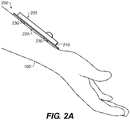
- Fig. 2A is a perspective view of an exemplary sensor 200 arranged over a body 100 (shown in phantom) to sense a physiological property thereof (e.g., potential or oxygen saturation).
- the sensor also synonymously referred to as a "biosensor”
- the sizing of the sensor 200 as shown is to provide a clear indication of the salient features.
- Fig. 2A is not necessarily drawn to scale and should not be relied upon for sizing or dimensional purposes.
- a sensor body 210 is defined by a skin-facing surface 220 and an opposing surface 225 that is visually accessible to a caregiver (not shown).
- the skin-facing surface 220 is arranged over the body 100 in which a plurality of conducting elements, e.g., sensor contacts 230, are disposed in spaced relation at least partly on the skin-facing surface 220.
- a plurality of conducting elements e.g., sensor contacts 230
- the term "skin-facing" refers to surfaces that face the subject's body.
- sensors used in the mouth or over the eye can have skin-facing surfaces 220 facing mucous membranes and the cornea, respectively, instead of the epidermis.
- the sensor contacts 230 form conducting elements through which a physiological property is sensed.
- the manner of conduction as defined herein can assume many forms such that the sensor contacts 230 can be conductive to optical energy, electrical energy, heat, or other physical characteristics or forms of energy.
- measurements made using the sensor 200 can be stored, and can be stored in association with, e.g., measurement timestamps, information about measurement devices (e.g., a serial number of the sensor 200), or information regarding the environmental conditions around the body 100 at the time of measurement.
- the sensor 200 can be any suitable size, e.g., blood-pressure-cuff size or fingertip-sized.
- Fig. 2B is a rear facing view of the exemplary sensor 200.
- a sensing element 235 is connected to the spaced set of sensor contacts 230. According to this specific version, a total of four (4) sensor contacts are shown in spaced relation along the skin facing surface of the sensor 200 wherein the sensing element 235 is disposed between the various sensor contacts 230 and substantially in the center of the skin facing surface 220. This number and positioning can be suitably varied, however, depending upon the application and the physiological or other parameter being measured or monitored.
- the sensing element 235 using the surrounding sensor contacts 230, is configured to detect a signal representative of a physiological parameter of the body 100, Fig. 2A , facing the skin-facing surface 220.
- An adhesive layer 270 can be coated over or otherwise affixed to the skin-facing surface 220 to at least temporarily hold the sensor 200 to the body 100.
- the adhesive layer 270 can include a conductive adhesive to affix the sensor 200 to the body 100 and permit the sensor contacts 230 to effectively contact the body 100.
- the sensor 200 can be integrated into a body-worn watch, wristband, ring band, or other garment.
- the sensor contacts 230 can convey any desired type of energy, e.g., thermal, electrical, optical, or acoustic, between the body 100 and the sensing element 235.
- the sensing element 235 detects a physiological property without connection with the sensor contacts 230.
- the sensing element 235 can include an accelerometer to measure body motion.
- the herein described sensor 200 further retains a wireless radio, such as a BLUETOOTH radio 260 (shown here in phantom).
- a wireless radio such as a BLUETOOTH radio 260 (shown here in phantom).
- BLUETOOTH radio 260 shown here in phantom
- other types of radio or wired or wireless transceiver can be alternatively used in lieu of the BLUETOOTH radio 260.
- the physiological parameter being measured by the sensor 200 can be but is not limited to blood pressure, pulse rate, pulse wave, skin conductance, galvanic skin response, temperature, electrocardiogram signal, electroencephalogram signal, electromyogram signal, heart rate variability, respiration, or other parameters. Additionally, the physiological parameter can also be blood glucose concentration, e.g., measured using an invasive or noninvasive continuous glucose monitor, or using an episodic glucose meter.
- Fig. 2C is a front facing view of the exemplary biomedical sensor 200.
- An indicator 240 is spaced apart from the skin-facing surface 220, Fig. 2A .
- the indicator is absent from the sensor 200 or is arranged over the skin-facing surface 220.
- the indicator is mounted to the surface 225 and opposed to the skin facing surface 220.
- the indicator 240 can include one or more of a speaker 241, an LED (e.g., a red LED 242 or a green LED 243), and a segmented display 250.
- the indicator 240 can also or alternatively include a vibratory or light- or sound-emitting element inside the sensor body 210.
- a light inside the sensor body 210 could emit light through a window (not shown) provided on the opposed surface 225 of the sensor 200.
- the indicator can be used to indicate whether the sensor 200 is correctly positioned. Examples of various indications of correct sensor positioning can include illumination from a green LED 243, pleasant audible tones from the speaker 241, and strong (or weak or absent) vibratory signals. Similarly, examples of various incorrect sensor positioning can include illumination by the red LED 242, unpleasant audible tones from the speaker 241, and weak (or strong) vibratory signals.
- a storage device 284 provided in the sensor 200 stores a physiological model.
- the storage device could also be separate from the sensor and coupled therewith.
- a processor 286, also retained within the sensor 200, is coupled to the sensing element 235, Fig. 2B , the indicator 240, and the storage device 284.
- the processor 286 determines a quality of sensor placement by comparing the signal representative of the physiological parameter of the body 100, Fig. 2A , to the stored physiological model, e.g., by executing stored program instructions, as discussed below.
- the processor 286 then operates the indicator 240 to provide a human-perceptible indication of the determined quality. In this way, the sensor 200 can provide the user feedback regarding the positioning of the sensor 200.
- the processor 286 is further configured to update the stored physiological model using the representative signal provided by the sensor element 235, Fig. 2B , if the comparison indicates the detected physiological parameter corresponds to the stored physiological model.
- the stored physiological model can be updated to follow gradual shifts or long-term trends, reducing the incidence of false negatives (indications a correctly-placed sensor is not correctly placed) and still maintaining the usefulness of the model for detecting incorrect sensor placements.
- Some common sensor-placement errors can be detected using data other than the signal representative of the physiological parameter of the body 100.
- certain sensors are designed to be worn throughout the day. In the course of everyday activity, a sensor disposed on the arm of a subject will tend to move in a very different way than a sensor disposed on either the leg or the torso. That is, sensors on the torso will typically tend to move either vertically or horizontally at any given time, and will also tend to move generally in one direction. Sensors disposed on the hand, however, will tend to remain within a narrow area, or undergo oscillatory motion superimposed on a directional trend (e.g., while walking). Motion data exhibiting these differences can be used to determine sensor placement.
- the herein described sensor 200 further includes a motion sensor 290 (shown in phantom), such as a one-, two-, or three-axis accelerometer.
- the storage device 284 further stores a motion model corresponding to a selected location on the body 100, e.g., one of locations 101, 102, 103, 104, 105, 106, or 107, all Fig. 1 .
- the processor 286 is further configured to record motion data from the motion sensor 290, compare the recorded motion data to the stored motion model, and then provide a human-perceptible indication of a result of the comparison. This latter indication can be provided using the indicator 240, as discussed herein.
- the storage device 284 can store multiple motion models corresponding to different locations on the body, and the processor 286 can compare the motion data to one or more of the models to determine which model (and thus which location) most closely match the motion data.
- the processor 286 is further configured to provide a human-perceptible indication of the selected location if the recorded motion data does not correspond to the stored motion model.
- the indication can be provided, e.g., via a user interface device 640, discussed below.
- the indication can also be provided using arrows (not shown) on the sensor 200, such as using a display, to indicate the direction the user should move the sensor 200 to reach the selected (e.g., preferred) location.
- Fig. 3 is a diagrammatic view of an exemplary indicator 240 and related sensor components.
- the illustrated indicator 240 includes a segmented display 250 having segments 351, 352, 353, 354, and 355.
- the segments 351, 352, 353, 354, and 355 are arranged similarly to a conventional signal-strength indicator for a mobile telephone.
- This arrangement is referred to herein as "sensor bars” or “sensor strength bars.”
- Sensor bars Analogous to providing strength of signal indication in a mobile telephone, having more of the segments 351, 352, 353, 354, and 355 illuminated provides a similar indication as to the determined quality of sensor placement.
- Using sensor bars advantageously provides information regarding placement in a manner many users are trained to associate with position. A user accustomed to walking or turning to improve mobile telephone reception, as indicated by bars for signal strength on the screen of the mobile telephone, can readily comprehend that a sensor should be moved around the body to improve placement quality, as indicated by the sensor bars.
- the indicator 240 includes a plurality of separately-activatable visual indicators, e.g., segments 351, 352, 353, 354, and 355.
- the processor 286 determines the quality using the model from the storage device 284, as discussed above.
- the processor 286 then activates a selected number of the visual indicators (e.g., segments 351, 352, 353, 354, and 355) to provide the human-perceptible indication, the selected number correlated with the determined quality.
- the segments 351, 352, 353, 354, and 355 can be arranged in configurations other than with progressively-increasing lengths. For example, each of the segments 351, 352, 353, 354, and 355 can have the same dimensions.
- the indicator 240 includes a seven-segment or other visual display configured to display a numeric or textual representation of the determined quality.
- the processor 286 is configured to activate none of the visual indicators, e.g., none of the segments 351, 352, 353, 354, and 355, if the signal corresponds to an absence or failed detection of the physiological parameter. For example, if the sensing element 235 is not able to detect the physiological property, perhaps because the sensor 200 is not disposed over the body 100, the processor 286 can activate none of the visual indicators.
- the processor 286 is further configured, in this example, to activate a selected first positive number of the visual indicators if the signal is detected but is not consistent with the physiological model.
- the sensing element 235 may detect light and provide a signal, but that signal will have very different properties (e.g., amplitude and propagation delay) than indicated by the stored physiological model.
- the processor 286 can be further configured to activate a selected second positive number of the visual indicators if the signal is detected and is consistent with the physiological model. According to this example, the selected second positive number is greater than the selected first positive number.
- the processor 286 can be configured to illuminate any of the following combinations: (a) none of the segments 351, 352, 353 if the signal is not detected; (b) the segment 351 if a signal is detected intermittently but the signal is not continuously present, or if the signal does not correspond to the physiological model; (c) the segments 351, 352 if the signal is detected and is regularly present (possibly with the exception of occasional noise or signal dropouts), and the signal conforms to the physiological model when the signal is present; or (d) the segments 351, 352, 353 if the signal is consistently present and conforms to the physiological model.
- the signal is consistent with the physiological model if 95% of the data points of the signal are within a corresponding point on the physiological model, ⁇ 30% or ⁇ 20%. Other signaling or indicating variants are herein contemplated.
- motion data can also be used.
- the processor 286 can be configured to illuminate none of the segments 351, 352, 353, 354, 355 if recorded motion data does not correspond to that of the motion model stored, for example, in storage device 284.
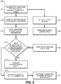
- Fig. 4 is a flowchart illustrating exemplary methods for measuring a physiological parameter of the body of a user.
- the methods can include automatically performing steps described herein using a processor.
- processing of flowchart 400 begins with step 405.
- steps 405. For clarity of explanation, reference is herein made to various components shown in Figs. 1-3 that can carry out or participate in the steps of the exemplary method. It should be noted, however, that other components can be used; that is, the exemplary method is not limited to being carried out by the identified components.
- Step 405 is a calibration step in which the physiological parameter of the body 100, Fig. 1 , is measured a plurality of times using a sensor 200, Fig. 2A , to provide respective measurements.
- the calibration measurements can be taken over any span or amount of time, at regular intervals or not, with the sensor 200 in a single location on the body 100, in different locations, or at a reference position.
- step 405 includes asking the user for information about the location of the sensor, e.g., by presenting a generic image of the body 100 on a touchscreen and asking the user to touch the screen to indicate the location of the sensor.
- the location can be stored in association with the respective measurements.
- the processor 286 can customize the generic image using data collected from the user, e.g., in steps 550 or 560, Fig. 5 .
- a measurement acceptance criterion is automatically computed using the respective measurements.
- the measurement acceptance criterion can include limits on the noise, amplitude, values, envelope, frequency, spectrum, or other properties of the measurements, taken in aggregate.
- the measurement acceptance criterion is computed as the envelope of the measurements.
- the measurements are aligned in time, e.g., each measurement is a time series of a blood pressure signal starting from the dicrotic notch.
- the measurement acceptance criterion is the mean ⁇ 1 ⁇ or ⁇ 2 ⁇ at each sample of the time series.
- the measurement acceptance criterion is detection of the dicrotic notch in the arterial pressure signal.
- the measurement acceptance criterion is determined at least in part based on the location received from the user in step 405. For example, if the user indicates that a blood-oxygen sensor has been placed on a pointer finger, the measurement acceptance criterion can be determined using stored representative data of variation at the pointer fingertip. In various embodiments, the measurement acceptance criterion can be determined for a secondary sensor or any of multiple sensors that work together, e.g., multiple ECG electrodes.
- the measurement acceptance criterion can be one element of the physiological model stored in the storage device 284, Fig. 2C .
- the physiological model can also include data from sensors other than the sensor 200 measured during the calibration step 405.
- the physiological model can include data from multiple sensors so that only certain combinations of ranges of readings from the various sensors conform to the physiological model.
- the calibration step 405 includes a step 407 of presenting an indication via a user interface (e.g., the user interface device 640, Fig. 6 ) that the user should perform a specific action, and a step 409 of measuring the physiological parameter while the user performs the action.
- a user interface e.g., the user interface device 640, Fig. 6
- the sensor can be a waist- or wrist-mounted motion sensor and the activity is walking.
- the measurement acceptance criterion thus corresponds to motion of the body part carrying the sensor. This correspondence permits measuring gait while walking, and disregarding data collected while standing still, thereby reducing measurement noise.
- the sensor is a heart rate monitor, the activity is jogging, and the measurement acceptance criterion corresponds to heart rate ranges measured during that type of exercise.
- step 407 includes selecting a recommended user action based on sensor data or user data. For example, placement ratings received in step 550 ( Fig. 5 , discussed below) and medical-condition indications received in step 560 ( Fig. 5 , discussed below) can be used to select the user action. Information such as whether the user is handicapped and the user's regular level of exercise can be used to select an activity that will provide meaningful data without laying undue burden on the user. Data from a prior calibration step 405 can also be used.
- Step 415 is a testing step in which the physiological parameter of the body is measured using the sensor 200 to provide a test measurement.
- Step 415 can be performed, e.g., at regular intervals or on demand.
- the processor 286 automatically determines whether the test measurement corresponds to the measurement acceptance criterion obtained from the computing step 410.
- the measurement acceptance criterion is an envelope
- the test measurement corresponds to the criterion if the points of the test measurement are within the envelope, or if 95% or 99% of the points are within the envelope.
- a test measurement corresponds to a range criterion (e.g., mean ⁇ ⁇ ) criteria if each point falls (or a selected percentage of the points fall) within the appropriate range.
- the measurement will not correspond to the measurement acceptance criterion determined for the pointer finger.
- the processor 286 automatically operates the indicator 240 of the sensor in order to provide a human-perceptible indication of the results of the determining step. If the test measurement does not conform to the measurement acceptance criterion, it may be that the sensor 200 is not in the correct location on the body 100. Accordingly, the processor 286 can illuminate the red LED 242, Fig. 2C , or otherwise indicate to the user or a caregiver or HCP that the sensor position should be checked. In various aspects, if the measured signal has high quality (e.g., the noise levels are low and there are few transients present) but the data are out of the range of the measurement acceptance criterion, an indication can be presented that the user may consider it worthwhile to seek medical advice. For example, if the user's body temperature begins to trend upward smoothly and passes the upper limit of the measurement acceptance criterion (e.g., 105°F) while still moving smoothly and consistently, the user may wish to determine whether the user has a severe fever.
- the measurement acceptance criterion e.g.,
- the processor 286 stores the results of the determination and an indication of the location of the sensor, e.g., in step 425.
- This stored data can be used in step 540, Fig. 5 , discussed below, in determining a subsequent sensor site.
- the results and the test-measurement data can be stored, e.g., for each measurement, or only for test measurements determined not to conform to the measurement acceptance criterion.
- the indicator 240 includes several separately-activatable visual indicators.
- step 425 can include step 427.
- the processor 286 activates a selected number n of the visual indicators (e.g., some or all of segments 351, 352, 353, 354, and 355, Fig. 3 ) to provide the human-perceptible indication.
- the selected number n can be correlated with the results of the determining step, e.g., in a sensor bars configuration such as that discussed above.
- n is correlated with, e.g., proportional to, the percentage p , 0% ⁇ p ⁇ 100%, of data points in the test measurement that meet the measurement acceptance criterion (e.g., an envelope).
- Steps 415, 420, and 425 can be repeated as desired, at regular or irregular intervals, or on demand, to take measurements.
- a blood pressure sensor 200 can be automatically activated every five minutes or every ten minutes to collect a measurement. If the test measurement does not conform to the measurement acceptance criterion, a care provider can be notified. Alternatively or additionally, the user can be notified and the test measurement flagged as being non-conforming. Non-conforming test measurement data can be disregarded, e.g., when computing historical averages from recorded test measurements.
- step 423 can follow step 420.
- the measurement acceptance criterion or other aspects of the physiological model are updated using the test measurement.
- step 423 can also be performed intermittently, once per day, once per session of measurements, or at other intervals.
- a session of measurements can be a time span in which numerous measurements are taken with a given sensor at a given location, e.g., the time a runner spends competing in a particular race.
- Data from multiple test measurements can be accumulated, and step 423 can be carried out once to update the physiological model using the accumulated measurements. Processing as described above with reference to computing step 410 can be performed to update the physiological model.
- the measurement acceptance criterion is that the test measurement be within 30% of the mean of the calibration measurements.
- Step 423 is carried out at the end of each sensor session to update information regarding that mean in the physiological model and in the measurement acceptance criterion. In this way, during the next sensor session, any deviation of more than 30% from the previous session's data will be indicated, e.g., by a drop in the number of sensor bars.
- the processor 286 can determine that the user is performing an activity different from the activity for which the calibration step 405 was performed, or that the sensor's environment has changed. Accordingly, decision step 420 is followed by step 422.
- the processor 286 deactivates the sensor 200 for a selected period of time.
- the term “deactivation” can refer to, e.g., powering down the sensor 200, or placing one or more component(s) of sensor 200 in a "sleep,” “passive,” or “suspend” state.
- a sensor 200 calibrated to measure the user's heart rate at rest can deactivate to save battery power while the user is exercising, then re-activate once the exercise is complete.
- the sensor 200 can begin to detach from the body 100 or lose electrical contact therewith.
- the sensor 200 calibrated for heart rate while jogging can go to sleep or otherwise temporarily deactivate when it is no longer possible to take accurate readings.
- a photoplasmography sensor provides noisy results if skin contact is impaired as a result of mechanical stress whiles the user is jogging. The sensor can be deactivated until improved skin contact is present.
- the onset of sleep can be heralded by the sensor bars ( Fig. 3 ). As contact degrades, the bars can drop. The sensor can deactivate (sleep) when the bars drop to zero bars illuminated.
- the processor 286 can periodically wake up from a sleep state and repeat steps 415 and 420 to determine whether to return the sensor 200 to normal operation.
- the sensing element 235, Fig. 2B can be configured to provide an interrupt signal to the processor 286 to wake up the processor 286 when conditions do meet or are likely to meet the measurement acceptance criterion.
- Step 422 and steps 407, 409 can also be used independently of each other.
- Fig. 5 is a flowchart illustrating further exemplary methods for measuring a physiological parameter of the body of a user. These methods can be used in combination with the methods shown in Fig. 4 , as is discussed below. The methods can include automatically performing steps described herein using a processor. For purposes of an exemplary embodiment, processing of flowchart 500 begins with step 505. For clarity of explanation, reference is herein made to various components shown in Figs. 1-3 and steps shown in Fig. 4 that can carry out or participate in the steps of the exemplary method. It should be noted, however, that other components or steps can be used; that is, the exemplary method is not limited to being carried out by the identified components or steps.
- step 505 an indication of a sensor site on the body is presented via a user interface, e.g., a touchscreen 630, Fig. 6 .
- a user interface e.g., a touchscreen 630, Fig. 6 .
- an image similar to Fig. 1 can be shown, with the sensor site (e.g., the location 101) visually highlighted.
- a physiological model corresponding to the indicated sensor site is retrieved from the storage device 284.
- the physiological model for an optical pulse oximeter can indicate the wavelengths of light to be used and the range of absorptions of those wavelengths by blood with typical arterial oxygen content (e.g., 16 to 22 ml O 2 /dL).
- typical arterial oxygen content e.g., 16 to 22 ml O 2 /dL
- a measurement that detects absorption outside the modeled range corresponding to the typical oxygen content can indicate that the sensor is incorrectly placed.
- step 515 the physiological parameter of the body 100 is measured using the sensor 200, Fig. 2A . This can be done as described above with reference to the sensing element 235, Fig. 2B .
- step 520 the measured physiological parameter is automatically compared to the retrieved physiological model. This can be done by the processor 286.
- Step 525 is an optional second operating step.
- the processor 286 can automatically operate the indicator 240 to provide a human-perceptible indication of the result of the comparing step (e.g., by lighting the red LED 242 or the green LED 243, both Fig. 2C ).
- decision step 530 it is determined whether the measured physiological parameter corresponds to the retrieved physiological model. If so, measurements can be collected using the sensor 200. Steps shown in flowchart 400 can be carried out, as indicated ("operate sensor"), if not, the next step can be step 540.
- Step 540 is a recommending step in which a second sensor site on the body is automatically determined, e.g., using the processor 286. Examples of how this recommendation is made are discussed below.
- the next step is step 505.
- the presenting-indication step 505, the retrieving step 510, the measuring step 515, the comparing step 520, the second operating step 525, the decision step 530, and (if necessary) the recommending step 540 can be repeated one or more times with the second sensor site or subsequent recommendations of alternative sensor sites. This advantageously permits a user to move the sensor to different locations on the body 100 and receive feedback about whether each of the locations is an appropriate site for taking measurements using the sensor 200.
- the motion can be user-directed, in which situation the user positions the sensor at the user's discretion, and the processor 286 determines whether the user-selected site can be used for measuring.
- the motion can also be system-directed, in that the processor 286 can present a series of recommended sensor sites by repeating this loop, and can collect one or more measurement(s) at each site. In either situation, the processor 286 can store measurement acceptance criteria or physiological models for each of a plurality of locations, and can recommend one of the pluralities of locations having the lowest error bands or the most consistent data.
- previous measurements and related data can also be used.
- sensor rotation can take into account locations used recently, e.g., within the last week or month.
- user information about the location of the sensor can also be used, e.g., for sensor rotation, or to differentiate between otherwise-equivalent locations (such as the left side of the waist vs. the right side of the waist).
- step 540 can include one or both of steps 542, 544.
- Step 542 is preceded by steps 550, 555; step 544 is preceded by steps 560, 565.
- the user provides ratings for of sensor placements in respective regions of the body.
- Each rating indicates the user's preference for placing a sensor (whether of a specific type or of any type) in the corresponding region of the body.
- a user may not wish to wear a gait sensor on the wrist. For that user, the combination of (gait sensor, wrist) has a low rating (e.g., *).
- the combination of (gait sensor, waist) can have a high rating (e.g., *****).
- unrated combinations are assigned a default rating. If the default rating is ***, then (gait sensor, waist) will rank above (gait sensor, wrist) with a * rating.
- the processor 286 can solicit ratings via a questionnaire or in other ways. Ratings can represent the level of comfort or discomfort the user experiences when a particular sensor is attached to a particular region of the body.
- step 550 one or more user indication(s) of respective rating(s) of sensor placement(s) in respective region(s) of the body is/are received via the user interface (e.g., the touchscreen 630, Fig. 6 ).
- step 555 the received user indication(s) are stored in the storage device 284.
- the second sensor site is determined using the stored user indication(s) (rating(s)).
- the processor 286 can sort the possible sites for a particular sensor by rating and suggest them as the second sensor site in order from highest-ranked to lowest.
- the user or HCP provides medical information useful for determining the second sensor site. For example, for a person whose left leg has been amputated, no site on the left leg should be determined as the second sensor site, regardless of which sensor is to be used or how poorly any other site is rated. This is referred to herein as a rating of "N" for any sensor on the left leg; “N” represents any flag value distinct from any possible rating.
- some sensors must be moved between sensor sites periodically; this is referred to as "rotation.”
- continuous glucose monitor (CGM) sensors include a needle that punctures the skin, and are rotated periodically to permit the skin to heal. The medical information can indicate that rotation is required for a particular sensor.
- an indication of a medical condition of the user is received via the user interface.
- the indication is stored in the storage device 284.
- the indication can be provided by answering a questionnaire presented via the user interface.
- the indication can also be provided indirectly. Examples of medical condition indications include height, weight, and the names of any diseases or long-term conditions.
- the processor 286 receives an image of the user's body 100 via the user interface.
- the processor 286 analyzes the image to determine whether any limbs are missing, and stores the results of any such determination.
- Some types of optical sensors are calibrated to particular skin tones; the processor 286 can also analyze the image to determine the user's skin tone to provide more accurate results with such sensors.
- step 544 the second sensor site is determined using the stored indication. Any (sensor, site) pair with a rating of N is omitted from consideration to be the second sensor site. Steps 544 and 542 can be combined; after rating-N pairs are removed, the remaining pairs for the appropriate sensor type can be sorted by rating.
- Fig. 6 is a block diagram of an exemplary system to determine optimal placement of a sensor for measuring a physiological parameter of a user using sensors (e.g., biosensors) as described herein.
- the sensor 200 has a sensing element 235, Fig. 1 , configured to measure a physiological parameter.
- the sensor 200 also has a first transceiver 661 configured to communicate the measurement.
- a BLUETOOTH radio 260, Fig. 2B is an example of a first transceiver 661.
- a user interface device 640 includes a second transceiver 662 configured to receive the measurement from the first transceiver 661. Communication between the transceivers 661, 662 can be unidirectional, half-duplex bidirectional, or full-duplex bidirectional.
- the user interface device 640 can be, e.g., a smartphone, tablet computer, or personal computer running software (e.g., a smartphone app) to receive data from the sensor 200 and optionally control the operation of the sensor 200.
- the user interface device 640 can include a mouse, a keyboard, another computer (connected, e.g., via a network or a null-modem cable), a microphone and speech processor or other device(s) for receiving voice commands, a camera and image processor or other device(s) for receiving visual commands, e.g., gestures, or any device or combination of devices from which data is input to the processor 286.
- the processor 286 is associated with the user interface device 640.
- the processor 286 is configured to automatically determine, using the received measurement, whether a sensor position over the body at a time corresponding to the received measurement meets a selected acceptance criterion. This can be done as discussed above with reference to steps 415, 420, Fig. 4 , and steps 510, 515, 520, 530, Fig. 5 .
- the processor 286 is further configured to present sensor-position feedback to the user via the user interface device 640 if the received measurement does not meet the selected acceptance criterion.
- the user interface device 640 can include the touchscreen 630 configured to present the sensor-position feedback.
- the touchscreen 630 can also serve as an indicator 240, as discussed above with reference to Fig. 2C .
- the user interface device 640 (e.g., a smartphone) is separate from the sensor 200.
- the first and second transceivers 661, 662 can include respective radio-frequency communications transceivers, e.g., for WIFI, BLUETOOTH, ZIGBEE, ALOHA, or other radio communications protocols; or infrared (e.g., IrDA) or other optical- or near-optical-wavelength protocols.
- the first and second transceivers 661, 662 can also or alternatively include respective wired-communications transceivers, e.g., for ETHERNET, FIREWIRE, I 2 C, or SPI.
- the user interface device 640 is integrated with the sensor 200.
- the user interface device 640 can also or alternatively communicate with the sensor 200 via a cloud or other network service.
- the processor 286 and the storage device 284 can be incorporated within the user interface device 640 or arranged separately therefrom.
- the processor 286 is configured to receive a plurality of measurements from the sensor 200 via the first and second transceivers 661, 662.
- the processor 286 is configured to, concurrently with receiving the measurements, present respective sensor-position feedback for each of the plurality of measurements via the user interface device 640.
- a user can move the sensor to different locations on the body 100 and receive feedback before adhering the sensor 200 to the body 100.
- the feedback can be provided via the indicator 240 on the sensor 200 instead of or in addition to being provided via the user interface device 640.
- Feedback on the sensor 200 permits the sensor 200 to operate in a manner similar (from the user's perspective) to a metal detector or stud finder.
- the user can sweep the sensor 200 across the body 100 until, e.g., the sensor bars on the segmented display 250, or the green LED 243, or a tone on the speaker 241, all Fig. 2 , indicates that the sensor 200 is positioned correctly.
- the sensor 200 can then be adhered to the body 100 at that position, e.g., by peeling a non-stick backer (not shown) off the adhesive layer 270, Fig. 2B , and pressing the sensor 200 and the exposed adhesive layer 270 against the body 100.
- the non-stick backer has cutouts, recesses, or other features to permit the sensor contacts 230 to contact the skin on the body 100 even before the non-stick backer is peeled off. These features permit the sensor to be effectively swept across the body without snags while taking measurements, and further permits measurements to be taken once the sensor is applied to the body 100.
- the processor 286 is configured to store the measurements and present the feedback at a later time than the time of measurement, e.g., at the request of a user.
- the processor 286 can also store real-time feedback while presenting it or shortly thereafter.
- an electrode such as an electrode used in testing connectivity of ECG-measurement units, placed on the body at a central location sends out a signal with a selected waveform.
- the sensor 200 detects the signal after the signal travels through the body.
- the processor 286 determines the electrical conductivity of the body using the received signal. In various examples, the processor 286 determines the distance from the electrode or the position of the sensor 200 with respect to the electrode.
- the processor 286 then presents an indication of the determined location, e.g., via the user interface device 640 or the indicator 240.
- the processor 286 prompts the user for confirmation that the determined location is correct.
- the processor 286 receives and stores the user's answer. If the determined location is not correct, the processor 286 can also prompt for, receive, and store an indication from the user of the correct location.
- the determined or correct location can be used along with measurements of the waveform to determine the position of a sensor newly-placed on the body.
- the centralized electrode sends out an electrical signal to the sensor.
- the impedance is measured between centralized electrode and the sensor.
- An estimated distance between the electrode and the sensor is calculated using the measured impedance.
- the impedance can also be measured using the patient height and weight, in a manner similar to a bioelectrical impedance analyzer (BIA), e.g., as used for estimating body fat percentage.
- BIAs typically pass a current through the body via two electrodes and measure the voltage developed across those electrodes by the impedance of the body.
- the measured impedance can be correlated with the patient's height, weight, sex, and other factors to determine a sensor-to-electrode spacing corresponding to a particular measured impedance.
- sensors 200 include a marking implement (not shown) using semi-permanent (e.g., India ink) material.
- a button or other control (not shown) on or in the sensor 200 causes the marking implement to protrude from the sensor 200 to leave a mark on the body, e.g., a non-toxic-ink splotch. This mark serves as an alignment feature for replacing the sensor in the correct location after peeling off the backer.
- Various embodiments include a method of recommending a sensor site on a body, the method comprising presenting an indication of a location on the body to place the sensor; measuring a physiological parameter of the body using the sensor placed substantially in the indicated location; automatically determining whether the indicated location is a recommended sensor site using a processor based on the measured physiological parameter, and presenting an indication of the result of that determination using an indicator of the sensor; and, if the indicated location is not a recommended sensor site, automatically determining a second location on the body and presenting an indication of the second location.
- Various embodiments advantageously use multiple inputs (e.g., physiological, modeled, and user data) to determine where to place the sensor 200.
- Feedback mechanisms e.g., visual, audible, or tactile, on the sensor 200, the user interface device 640, a computer, or a smartphone
- Various embodiments advantageously permit the sensor to be positioned consistently over extended periods of time, even when a sensor is removed and replaced.
- Various embodiments monitor sensor performance, e.g., using measurement acceptance criteria as described above with reference to Fig. 4 . This can be done as part of sensor position determination, or the two can be done independently.
- the processor 286 includes one or more data processor(s) that implement processes of various embodiments described herein.
- a "data processor” is a device for processing data and can include a central processing unit (CPU), a desktop computer, a laptop computer, a mainframe computer, a personal digital assistant, a digital camera, a cellular phone, a smartphone, or any other device for processing data, managing data, or handling data, whether implemented with electrical, magnetic, optical, biological components, or otherwise.
- the phrase "communicatively connected” includes any type of connection, wired or wireless, between devices, data processors, or programs in which data can be communicated.
- Subsystems such as the storage device 284 and the user interface device 640 are shown separately from the processor 286 but can be stored completely or partially within the processor 286.
- the storage device 284 includes or is communicatively connected with one or more tangible non-transitory computer-readable storage medium(s) configured to store information, including the information needed to execute processes according to various embodiments.
- the term “device” does not imply that storage device 284 include only one piece of hardware that stores data.
- a "tangible non-transitory computer-readable storage medium” as used herein refers to any non-transitory device or article of manufacture that participates in storing instructions which may be provided to the processor 286 for execution. Such a non-transitory medium can be non-volatile or volatile.
- non-volatile media examples include floppy disks, flexible disks, or other portable computer diskettes, hard disks, magnetic tape or other magnetic media, Compact Discs and compact-disc read-only memory (CD-ROM), DVDs, BLU-RAY disks, HD-DVD disks, other optical storage media, Flash memories, read-only memories (ROM), and erasable programmable read-only memories (EPROM or EEPROM).
- volatile media include dynamic memory, such as registers and random access memories (RAM).
- Embodiments of the present invention can take the form of a computer program product embodied in one or more tangible non-transitory computer readable medium(s) having computer readable program code embodied thereon.
- Such medium(s) can be manufactured as is conventional for such articles, e.g., by pressing a CD-ROM.
- the program embodied in the medium(s) includes computer program instructions that can direct the processor 286 to perform a particular series of operational steps when loaded, thereby implementing functions or acts specified herein, e.g., measuring sensor data and determining sensor sites.
- the storage device 284 includes a memory 684, e.g., a random-access memory, and a disk 685, e.g., a tangible computer-readable storage device such as a hard drive or a solid-state flash drive.
- Computer program instructions are read into the memory 684 from the disk 685, or a wireless, wired, optical fiber, or other connection.
- the processor 286 then executes one or more sequences of the computer program instructions loaded into the memory 684, as a result performing process steps and other processing described herein. In this way, the processor 286 carries out a computer implemented process that provides technical effects described herein, e.g., measuring physiological properties of a patient's body.
- blocks of the flowchart illustrations or block diagrams herein, and combinations of those, can be implemented by computer program instructions.
- the memory 684 can also store data used by running programs.
- Program code to carry out methods described herein can execute entirely on a single processor 286 or on multiple communicatively-connected processors 286.
- code can execute wholly or partly on a user's computer and wholly or partly on a remote computer, e.g., a server.
- the remote computer can be connected to the user's computer through a network 690.
- the user's computer or the remote computer can be non-portable computers, such as conventional desktop personal computers (PCs), or can be portable computers such as tablets, cellular telephones, smartphones, or laptops.
- the user interface device 640 also can include a display device, a touchscreen, a processor-accessible memory, or any device or combination of devices to which data is output by the processor 286.
- the user interface device 640 includes a processor-accessible memory, such memory can be part of the storage device 284 even though the user interface device 640 and the storage device 284 are shown separately in Fig. 6 .
- the user interface device 640 can include one or more touchscreen(s), speaker(s), buzzer(s), vibrator(s), button(s), switch(es), jack(s), plug(s), or network connection(s).
- the processor 286 is communicatively connected to the network 690, e.g., via a communications interface or transceiver (not shown).
- the processor 286 can send messages and receive data, including program code, to and from the network 690.
- requested code for an application program e.g., a JAVA applet
- a network server (not shown) can retrieve the code from the medium and transmit it via the network 690 to the processor 286.
- the received code can be executed by the processor 286 as it is received, or stored in the storage device 284 for later execution.
- FIGS. 1-6 PARTS LIST FOR FIGS. 1-6:
Description
- This International Patent Application claims the benefits of priority under the Paris Convention and 35 USC §119 to prior filed
U.S. Provisional Patent Application S.N. 61/922,097 filed on December 31, 2013 - This application relates generally to the field of electronic systems for monitoring biological properties of a user's body, and more specifically to medical monitoring systems.
- The use of various types of sensors to evaluate one or more physiological characteristics or parameters of a patient is well known. For example, optical pulse oximetry sensors measure the level of oxygen saturation (SpO2) in a patient's blood. Typically, a light emitting diode (LED) transmits optical radiation of several different wavelengths, e.g., visible and infrared, through blood and tissue of a predetermined portion of a patient's body, such as the wrist or finger. A photodetector detects the light after it passes through the body. Different wavelengths of light are absorbed differently based on blood oxygen content, so detecting the optical attenuation at each wavelength permits the determination of oxygen saturation. In another example, electrocardiogram (ECG or EKG) electrodes are generally planar electrodes connected via wires to an ECG unit that measures the voltage across different pairs of the electrodes to monitor the patient's heart. It is generally required that sensors be correctly placed with respect to a specific body part to be measured. For example, an optical pulse oximetry sensor should be placed so that the optical path from the transmitter to the detector intersects a blood vessel. In like fashion, an ECG sensor should be placed on a part of the body that provides effective electrical contact across the skin (e.g., not on top of significant amounts of hair).
- Sensors are constructed in different forms to enable attachment to different portions of a patient's body. For example, optical oximetry sensors can operate by detecting light transmitted through the tissue or light reflected by the tissue. Transmission-mode sensors are useful for fingers and other narrow parts of the body. Reflection-mode sensors are useful for thicker parts of the body, e.g., the forehead or torso. Moreover, sensors are generally calibrated relative to their intended usage. For example, optical sensors are designed and calibrated depending on whether their intended use is as a transmission or reflectance sensor, and will be calibrated for a specific spacing, or range of spacings, between the emitters and the detector. Thus, even two transmission sensors, such as one intended for use on a fingertip and another intended for use on an earlobe, will typically have different calibrations. The calibration differences between a transmission sensor and a reflectance sensor are typically greater.
- Sensors are designed for specific locations on the body, as discussed above. Given this specificity, it can be difficult for caregivers to apply sensors correctly. This situation is exacerbated when patients must properly apply sensors to themselves, e.g., in outpatient or home-care situations. For example, a bandage-type transmission sensor intended for use on a fingertip, and which would normally be folded over or around the fingertip, may be unfolded and applied to another portion of the patient's body in a configuration like a reflectance sensor. However, in such a circumstance, not only are the placement of the sensor and measurement method different from what was intended, but the spacing between the emitters and detector is also significantly different from what was intended for the sensor. Thus, the misapplied sensor will not give accurate readings for the patient. Other misapplications of a sensor include placement on a site which, although positionally correct, is not suitable for optimal measurements. This situation may exist, for example, when the physical characteristics of the site are unsatisfactory to yield reliable measurements, e.g., due to sweat, hair, or position of subcutaneous fat. For example, although an oximeter calibrated for the pointer finger may be intended for use with either finger, differences between the patient's two pointer fingers may only permit the oximeter to be effectively used with one of those fingers. Moreover, the user or health care provider may unwittingly or carelessly position a physiologic sensor in whole or in part over an article of clothing.
-
US 2011/245622 A1 describes systems, methods, and devices for determining whether a medical sensor has been properly applied to a patient. A medical sensor interface may receive physiological data from a medical sensor applied to a patient. Data processing circuitry may be capable of being trained, using a learning-based algorithm, to determine whether the received physiological data indicates that the medical sensor has been properly applied to the patient. -
WO 2010/134010 A1 describes a sensing device for detecting the wearing position of the device with respect to a user. The device comprises a motion sensor for detecting a motion signal, a height sensor for detecting a height signal and a computing unit. The computing unit receives the motion signal and the height signal, and based thereon determines the wearing position of the sensing device with respect to the user. -
US 2007/060807 A1 describes a pair of light-receiving sections, each being composed of a plurality of light receiving regions so that by selecting a signal of the light receiving region which maximizes a reception signal, the correction direction of a wearing position may be displayed. -
US 2008/221414 A1 describes a method for determining contact of a sensor with a patient's tissue. The method comprises comparing the intensity of detected light at a first wavelength to a threshold. -
WO 2013/076656 A1 describes a wearable measurement device for measuring a physiological parameter of a user. -
US 5 494 043 A describes an arterial sensor. - In one embodiment, therefore, a biomedical sensor has been devised. The biomedical sensor according to an embodiment of the present invention is defined in appended independent claim 1.
- In another embodiment, a method of determining optimal placement of a sensor on a user's body for measuring a physiological parameter of the user is provided. The method according to an embodiment of the present invention is defined in appended independent claim 6.
- In another embodiment, a system to determine optimal placement of a sensor on a user's body for measuring a physiological parameter of the user is provided. The system according to an embodiment of the present invention is defined in appended independent claim 12.
- Each of these embodiments, exemplary of the present invention, can provide improved feedback regarding sensor positioning. Various embodiments advantageously provide users and home-care providers ways of positioning sensors accurately. Various embodiments provide detection of conditions that may interfere with sensor readings.
- Accordingly, in any of the embodiments described earlier, the following features may also be utilized in various combinations with the previously disclosed embodiments. For example, the biomedical sensor can include the indicator having plural separately-activatable visual indicators, in which the processor is configured to activate a selected number of the visual indicators to provide the human-perceptible indication, the selected number correlated with the determined quality. The processor can be configured to activate none of the visual indicators if the signal corresponds to an absence or failed detection of the physiological parameter; to activate a selected first positive number of the visual indicators if the signal is not consistent with the physiological model; and to activate a selected second positive number of the visual indicators if the signal is consistent with the physiological model, the selected second positive number being greater than the selected first positive number. The physiological parameter can be selected from the group consisting of blood pressure, pulse rate, skin conductance, galvanic skin response, temperature, electrocardiogram signal, blood glucose concentration, and heart rate variability. The processor can be further configured to update the stored physiological model using the signal if the comparison indicates the detected physiological parameter corresponds to the stored physiological model.
- In various examples, the method can include in which the calibration step may include presenting an indication via a user interface that the user should perform a specific action, and measuring the physiological parameter while the user performs the action. The operating step can include deactivating the sensor for a selected period of time if the test measurement does not correspond to the measurement acceptance criterion obtained from the computing step. The indicator can include plural separately-activatable visual indicators and the operating step can include activating a selected number of the visual indicators to provide the human-perceptible indication, the selected number correlated with the results of the determining step. The method can include presenting an indication of a sensor site on the body via a user interface; retrieving from a storage device a physiological model corresponding to the indicated sensor site; measuring the physiological parameter of the body using the sensor; automatically comparing the measured physiological parameter to the retrieved physiological model; and a second operating step of automatically operating the indicator to provide a human-perceptible indication of the result of the comparing step. The method can include, if the measured physiological parameter does not correspond to the retrieved physiological model, performing a recommending step of automatically determining a second sensor site on the body; and repeating the presenting-indication, retrieving, measuring, and comparing steps, and the second operating step, using the second sensor site. The method can include receiving via the user interface one or more user indication(s) of respective rating(s) of sensor placement(s) in respective region(s) of the body and storing the received user indication(s) in the storage device, the recommending step including determining the second sensor site using the stored user indication(s). The method can include receiving via the user interface an indication of a medical condition of the user and storing the indication in the storage device, the recommending step including determining the second sensor site using the stored indication.
- The system can include the user interface device being separate from the sensor, and the first and second transceivers including radio-frequency communications transceivers. The user interface device can include a touchscreen configured to present the sensor-position feedback. The processor can be configured to receive a plurality of measurements from the sensor via the first and second transceivers and to concurrently present respective sensor-position feedback for each of the plurality of measurements via the user interface device. The system can include a storage device configured to store data representing the selected acceptance criterion.
- In the aforementioned aspects of the disclosure, the steps of calibration, computing, testing, determining, operating, presenting, retrieving, measuring, comparing, operating (the second operating step), recommending, repeating, or receiving indications (possibly in conjunction with an equation) may be performed be an electronic circuit or a processor. These steps may also be implemented as executable instructions stored on a computer readable medium; the instructions, when executed by a computer may perform the steps of any one of the aforementioned methods.
- In additional aspects of the disclosure, there are computer readable media, each medium comprising executable instructions, which, when executed by a computer, perform the steps of any one of the aforementioned methods.
- In additional aspects of the disclosure, there are devices, such as sensors, or smartphones or other user-interface devices, each comprising an electronic circuit or processor configured to perform steps of any one of the aforementioned methods.
- These and other embodiments, features and advantages will become apparent to those skilled in the art when taken with reference to the following more detailed description of various exemplary embodiments of the invention in conjunction with the accompanying drawings that are first briefly described.
- The accompanying drawings, which are incorporated herein and constitute part of this specification, illustrate presently preferred embodiments of the invention, and, together with the general description given above and the detailed description given below, serve to explain features of the invention. For the sake of clarity, like reference numerals herein represent like elements.
-
FIG. 1 is a graphical representation of a patient illustrating exemplary locations at which a sensor, such as a biosensor, can be placed; -
FIGS. 2A-2C are a perspective view, a rear view, and a front view, respectively, of an exemplary biosensor, showing components of the biosensor according to various embodiments; -
FIG. 3 is a diagram of an exemplary indicator and related components; -
FIGS. 4 and5 are flowcharts illustrating exemplary methods for measuring a physiological parameter of the body of a user; and -
FIG. 6 is a block diagram of an exemplary system to determine optimal placement of a sensor for measuring a physiological parameter of a user. - The following detailed description should be read with reference to the drawings, in which like elements in different drawings are identically numbered. The drawings, which are not necessarily to scale, depict selected embodiments and are not intended to limit the scope of the invention or the attached claims.
- As used herein, the terms "about" or "approximately" for any numerical values or ranges indicate a suitable dimensional tolerance that allows the part or collection of components to function for its intended purpose as described herein. More specifically, "about" or "approximately" may refer to the range of values not at least ±10% of the recited value, e.g. "about 90%" may refer to the range of values from 81% to 99%. As used herein, the phrase "electrical signal" or "signal" is intended to include direct current signals, alternating signals, or any signal within the electromagnetic spectrum. The terms "processor," "microprocessor," and "microcontroller" are intended to have the same meaning and are intended to be used interchangeably. Throughout this disclosure, the terms "patient" and "subject" are used interchangeably. These terms can refer to any human or animal subject and are not intended to limit the systems or methods to human use, although use of aspects described herein for a human patient represents a preferred embodiment. Furthermore, in this disclosure, the term "user" can refer to a patient using a biosensor or another person (e.g., a parent or guardian, nursing staff member, home care employee, or other caretaker) using such a device. The term "healthcare provider" or "HCP" refers generally to doctors, nurses, and individuals other than the patient that provide health care services to the patient.
- Various embodiments described herein advantageously permit positioning a sensor for the measurement of physiologic sensor data without extensive or complicated sensor-placement processes. This permits measuring more-consistent, more-reliable sensor data, which in turn can improve user perceptions of the trust that can be placed in the system. As used herein, the term "sensor" refers to various types of sensors, including biosensors for obtaining physiological data of a patient.
-
Fig. 1 is a graphical representation of thebody 100 of a patient illustrating exemplary locations at which a sensor, such as biosensor, can be placed for obtaining physiological parameter data.Locations locations locations - Each of the
locations -
Fig. 2A is a perspective view of anexemplary sensor 200 arranged over a body 100 (shown in phantom) to sense a physiological property thereof (e.g., potential or oxygen saturation). In this specific example, the sensor (also synonymously referred to as a "biosensor") 200 are placed over a wrist location, identified aslocation 106 according toFig. 1 . The sizing of thesensor 200 as shown is to provide a clear indication of the salient features. To that end,Fig. 2A is not necessarily drawn to scale and should not be relied upon for sizing or dimensional purposes. According to this exemplary embodiment, asensor body 210 is defined by a skin-facingsurface 220 and an opposingsurface 225 that is visually accessible to a caregiver (not shown). The skin-facingsurface 220 is arranged over thebody 100 in which a plurality of conducting elements, e.g.,sensor contacts 230, are disposed in spaced relation at least partly on the skin-facingsurface 220. The term "skin-facing" refers to surfaces that face the subject's body. For example, sensors used in the mouth or over the eye can have skin-facingsurfaces 220 facing mucous membranes and the cornea, respectively, instead of the epidermis. For purposes of this embodiment, thesensor contacts 230 form conducting elements through which a physiological property is sensed. The manner of conduction as defined herein can assume many forms such that thesensor contacts 230 can be conductive to optical energy, electrical energy, heat, or other physical characteristics or forms of energy. Throughout this disclosure, measurements made using thesensor 200 can be stored, and can be stored in association with, e.g., measurement timestamps, information about measurement devices (e.g., a serial number of the sensor 200), or information regarding the environmental conditions around thebody 100 at the time of measurement. Thesensor 200 can be any suitable size, e.g., blood-pressure-cuff size or fingertip-sized. -
Fig. 2B is a rear facing view of theexemplary sensor 200. Asensing element 235 is connected to the spaced set ofsensor contacts 230. According to this specific version, a total of four (4) sensor contacts are shown in spaced relation along the skin facing surface of thesensor 200 wherein thesensing element 235 is disposed between thevarious sensor contacts 230 and substantially in the center of theskin facing surface 220. This number and positioning can be suitably varied, however, depending upon the application and the physiological or other parameter being measured or monitored. Thesensing element 235, using the surroundingsensor contacts 230, is configured to detect a signal representative of a physiological parameter of thebody 100,Fig. 2A , facing the skin-facingsurface 220. Anadhesive layer 270 can be coated over or otherwise affixed to the skin-facingsurface 220 to at least temporarily hold thesensor 200 to thebody 100. Theadhesive layer 270 can include a conductive adhesive to affix thesensor 200 to thebody 100 and permit thesensor contacts 230 to effectively contact thebody 100. Alternatively, thesensor 200 can be integrated into a body-worn watch, wristband, ring band, or other garment. Thesensor contacts 230 can convey any desired type of energy, e.g., thermal, electrical, optical, or acoustic, between thebody 100 and thesensing element 235. In at least one embodiment, thesensing element 235 detects a physiological property without connection with thesensor contacts 230. For example, thesensing element 235 can include an accelerometer to measure body motion. - Still referring to
Fig. 2A , the herein describedsensor 200 further retains a wireless radio, such as a BLUETOOTH radio 260 (shown here in phantom). As discussed in a later portion, other types of radio or wired or wireless transceiver can be alternatively used in lieu of the BLUETOOTH radio 260. The physiological parameter being measured by thesensor 200 can be but is not limited to blood pressure, pulse rate, pulse wave, skin conductance, galvanic skin response, temperature, electrocardiogram signal, electroencephalogram signal, electromyogram signal, heart rate variability, respiration, or other parameters. Additionally, the physiological parameter can also be blood glucose concentration, e.g., measured using an invasive or noninvasive continuous glucose monitor, or using an episodic glucose meter. -
Fig. 2C is a front facing view of the exemplarybiomedical sensor 200. Anindicator 240 is spaced apart from the skin-facingsurface 220,Fig. 2A . In other examples, the indicator is absent from thesensor 200 or is arranged over the skin-facingsurface 220. In the exemplary embodiment shown, the indicator is mounted to thesurface 225 and opposed to theskin facing surface 220. Theindicator 240 can include one or more of aspeaker 241, an LED (e.g., ared LED 242 or a green LED 243), and asegmented display 250. Theindicator 240 can also or alternatively include a vibratory or light- or sound-emitting element inside thesensor body 210. For example, a light inside thesensor body 210 could emit light through a window (not shown) provided on theopposed surface 225 of thesensor 200. The indicator can be used to indicate whether thesensor 200 is correctly positioned. Examples of various indications of correct sensor positioning can include illumination from agreen LED 243, pleasant audible tones from thespeaker 241, and strong (or weak or absent) vibratory signals. Similarly, examples of various incorrect sensor positioning can include illumination by thered LED 242, unpleasant audible tones from thespeaker 241, and weak (or strong) vibratory signals. - According to this exemplary embodiment, a
storage device 284 provided in thesensor 200 stores a physiological model. Alternatively and discussed in other embodiments, the storage device could also be separate from the sensor and coupled therewith. Aprocessor 286, also retained within thesensor 200, is coupled to thesensing element 235,Fig. 2B , theindicator 240, and thestorage device 284. Theprocessor 286 determines a quality of sensor placement by comparing the signal representative of the physiological parameter of thebody 100,Fig. 2A , to the stored physiological model, e.g., by executing stored program instructions, as discussed below. Theprocessor 286 then operates theindicator 240 to provide a human-perceptible indication of the determined quality. In this way, thesensor 200 can provide the user feedback regarding the positioning of thesensor 200. - It is generally recognized that patients' bodies change physiologically over time, e.g., due to aging. In various embodiments, the
processor 286 is further configured to update the stored physiological model using the representative signal provided by thesensor element 235,Fig. 2B , if the comparison indicates the detected physiological parameter corresponds to the stored physiological model. In this way, the stored physiological model can be updated to follow gradual shifts or long-term trends, reducing the incidence of false negatives (indications a correctly-placed sensor is not correctly placed) and still maintaining the usefulness of the model for detecting incorrect sensor placements. - Some common sensor-placement errors can be detected using data other than the signal representative of the physiological parameter of the
body 100. For example, certain sensors are designed to be worn throughout the day. In the course of everyday activity, a sensor disposed on the arm of a subject will tend to move in a very different way than a sensor disposed on either the leg or the torso. That is, sensors on the torso will typically tend to move either vertically or horizontally at any given time, and will also tend to move generally in one direction. Sensors disposed on the hand, however, will tend to remain within a narrow area, or undergo oscillatory motion superimposed on a directional trend (e.g., while walking). Motion data exhibiting these differences can be used to determine sensor placement. - Still referring to
Fig. 2C , the herein describedsensor 200 further includes a motion sensor 290 (shown in phantom), such as a one-, two-, or three-axis accelerometer. Thestorage device 284 further stores a motion model corresponding to a selected location on thebody 100, e.g., one oflocations Fig. 1 . Theprocessor 286 is further configured to record motion data from themotion sensor 290, compare the recorded motion data to the stored motion model, and then provide a human-perceptible indication of a result of the comparison. This latter indication can be provided using theindicator 240, as discussed herein. For purposes described herein, thestorage device 284 can store multiple motion models corresponding to different locations on the body, and theprocessor 286 can compare the motion data to one or more of the models to determine which model (and thus which location) most closely match the motion data. - In several of these aspects, the
processor 286 is further configured to provide a human-perceptible indication of the selected location if the recorded motion data does not correspond to the stored motion model. The indication can be provided, e.g., via a user interface device 640, discussed below. The indication can also be provided using arrows (not shown) on thesensor 200, such as using a display, to indicate the direction the user should move thesensor 200 to reach the selected (e.g., preferred) location. -
Fig. 3 is a diagrammatic view of anexemplary indicator 240 and related sensor components. The illustratedindicator 240 includes asegmented display 250 havingsegments segments segments - In general, in various embodiments, the
indicator 240 includes a plurality of separately-activatable visual indicators, e.g.,segments processor 286 determines the quality using the model from thestorage device 284, as discussed above. Theprocessor 286 then activates a selected number of the visual indicators (e.g.,segments segments segments processor 286 illuminate thesegments indicator 240 includes a seven-segment or other visual display configured to display a numeric or textual representation of the determined quality. - In an example, the
processor 286 is configured to activate none of the visual indicators, e.g., none of thesegments sensing element 235 is not able to detect the physiological property, perhaps because thesensor 200 is not disposed over thebody 100, theprocessor 286 can activate none of the visual indicators. Theprocessor 286 is further configured, in this example, to activate a selected first positive number of the visual indicators if the signal is detected but is not consistent with the physiological model. For example, if a transmissive optical sensor is used in a reflective configuration, thesensing element 235 may detect light and provide a signal, but that signal will have very different properties (e.g., amplitude and propagation delay) than indicated by the stored physiological model. Theprocessor 286 can be further configured to activate a selected second positive number of the visual indicators if the signal is detected and is consistent with the physiological model. According to this example, the selected second positive number is greater than the selected first positive number. - According to the exemplary embodiment and specifically using the
segments processor 286 can be configured to illuminate any of the following combinations: (a) none of thesegments segment 351 if a signal is detected intermittently but the signal is not continuously present, or if the signal does not correspond to the physiological model; (c) thesegments segments - As discussed above, motion data can also be used. For example, the
processor 286 can be configured to illuminate none of thesegments storage device 284. -
Fig. 4 is a flowchart illustrating exemplary methods for measuring a physiological parameter of the body of a user. The methods can include automatically performing steps described herein using a processor. For purposes of an exemplary embodiment, processing offlowchart 400 begins withstep 405. For clarity of explanation, reference is herein made to various components shown inFigs. 1-3 that can carry out or participate in the steps of the exemplary method. It should be noted, however, that other components can be used; that is, the exemplary method is not limited to being carried out by the identified components. - Step 405 is a calibration step in which the physiological parameter of the
body 100,Fig. 1 , is measured a plurality of times using asensor 200,Fig. 2A , to provide respective measurements. The calibration measurements can be taken over any span or amount of time, at regular intervals or not, with thesensor 200 in a single location on thebody 100, in different locations, or at a reference position. In various embodiments,step 405 includes asking the user for information about the location of the sensor, e.g., by presenting a generic image of thebody 100 on a touchscreen and asking the user to touch the screen to indicate the location of the sensor. The location can be stored in association with the respective measurements. Theprocessor 286 can customize the generic image using data collected from the user, e.g., insteps Fig. 5 . - In
step 410, using theprocessor 286,Fig. 2C , a measurement acceptance criterion is automatically computed using the respective measurements. The measurement acceptance criterion can include limits on the noise, amplitude, values, envelope, frequency, spectrum, or other properties of the measurements, taken in aggregate. In an example, the measurement acceptance criterion is computed as the envelope of the measurements. In another example, the measurements are aligned in time, e.g., each measurement is a time series of a blood pressure signal starting from the dicrotic notch. In this example, the measurement acceptance criterion is the mean ±1σ or ±2σ at each sample of the time series. In another example, the measurement acceptance criterion is detection of the dicrotic notch in the arterial pressure signal. If the notch is not detected, thesensor 200 is not correctly positioned. Detection of the notch can cause theprocessor 286 to activate two or three bars on a three-bar segmenteddisplay 250. In at least one example, the measurement acceptance criterion is determined at least in part based on the location received from the user instep 405. For example, if the user indicates that a blood-oxygen sensor has been placed on a pointer finger, the measurement acceptance criterion can be determined using stored representative data of variation at the pointer fingertip. In various embodiments, the measurement acceptance criterion can be determined for a secondary sensor or any of multiple sensors that work together, e.g., multiple ECG electrodes. - The measurement acceptance criterion can be one element of the physiological model stored in the
storage device 284,Fig. 2C . The physiological model can also include data from sensors other than thesensor 200 measured during thecalibration step 405. The physiological model can include data from multiple sensors so that only certain combinations of ranges of readings from the various sensors conform to the physiological model. - Various sensors are designed for measuring the body under specific conditions. The calibration can thus be performed under those conditions. Specifically, in various embodiments, the
calibration step 405 includes astep 407 of presenting an indication via a user interface (e.g., the user interface device 640,Fig. 6 ) that the user should perform a specific action, and astep 409 of measuring the physiological parameter while the user performs the action. Examples of specific actions including standing still, sitting, walking, and jogging. For example, the sensor can be a waist- or wrist-mounted motion sensor and the activity is walking. The measurement acceptance criterion thus corresponds to motion of the body part carrying the sensor. This correspondence permits measuring gait while walking, and disregarding data collected while standing still, thereby reducing measurement noise. According to another example, the sensor is a heart rate monitor, the activity is jogging, and the measurement acceptance criterion corresponds to heart rate ranges measured during that type of exercise. - In various aspects,
step 407 includes selecting a recommended user action based on sensor data or user data. For example, placement ratings received in step 550 (Fig. 5 , discussed below) and medical-condition indications received in step 560 (Fig. 5 , discussed below) can be used to select the user action. Information such as whether the user is handicapped and the user's regular level of exercise can be used to select an activity that will provide meaningful data without laying undue burden on the user. Data from aprior calibration step 405 can also be used. - Step 415 is a testing step in which the physiological parameter of the body is measured using the
sensor 200 to provide a test measurement. Step 415 can be performed, e.g., at regular intervals or on demand. - In
decision step 420, theprocessor 286 automatically determines whether the test measurement corresponds to the measurement acceptance criterion obtained from thecomputing step 410. In various examples, if the measurement acceptance criterion is an envelope, the test measurement corresponds to the criterion if the points of the test measurement are within the envelope, or if 95% or 99% of the points are within the envelope. Similarly, a test measurement corresponds to a range criterion (e.g., mean ± σ) criteria if each point falls (or a selected percentage of the points fall) within the appropriate range. Continuing the blood-oxygen example above, if the user indicates that the sensor is on a pointer finger but the data are more consistent with middle-finger readings than pointer-finger readings, the measurement will not correspond to the measurement acceptance criterion determined for the pointer finger. - In
step 425, theprocessor 286 automatically operates theindicator 240 of the sensor in order to provide a human-perceptible indication of the results of the determining step. If the test measurement does not conform to the measurement acceptance criterion, it may be that thesensor 200 is not in the correct location on thebody 100. Accordingly, theprocessor 286 can illuminate thered LED 242,Fig. 2C , or otherwise indicate to the user or a caregiver or HCP that the sensor position should be checked. In various aspects, if the measured signal has high quality (e.g., the noise levels are low and there are few transients present) but the data are out of the range of the measurement acceptance criterion, an indication can be presented that the user may consider it worthwhile to seek medical advice. For example, if the user's body temperature begins to trend upward smoothly and passes the upper limit of the measurement acceptance criterion (e.g., 105°F) while still moving smoothly and consistently, the user may wish to determine whether the user has a severe fever. - In various aspects, the
processor 286 stores the results of the determination and an indication of the location of the sensor, e.g., instep 425. This stored data can be used instep 540,Fig. 5 , discussed below, in determining a subsequent sensor site. The results and the test-measurement data can be stored, e.g., for each measurement, or only for test measurements determined not to conform to the measurement acceptance criterion. - In various examples such as those described above with reference to
Fig. 3 , theindicator 240 includes several separately-activatable visual indicators. In these examples, step 425 can includestep 427. Instep 427, theprocessor 286 activates a selected number n of the visual indicators (e.g., some or all ofsegments Fig. 3 ) to provide the human-perceptible indication. The selected number n can be correlated with the results of the determining step, e.g., in a sensor bars configuration such as that discussed above. In an example, n is correlated with, e.g., proportional to, the percentage p, 0% ≤ p ≤ 100%, of data points in the test measurement that meet the measurement acceptance criterion (e.g., an envelope). The proportionality can be, e.g., linear (e.g., four bars, with n such that p ≥ n×4) or logarithmic (e.g., four bars, with n = 4 for p ≥ 99%, n = 3 for p ≥ 96%, n = 2 for p ≥ 90%, n = 1 for p ≥ 68%, and n = 0 for p<68%). -
Steps blood pressure sensor 200 can be automatically activated every five minutes or every ten minutes to collect a measurement. If the test measurement does not conform to the measurement acceptance criterion, a care provider can be notified. Alternatively or additionally, the user can be notified and the test measurement flagged as being non-conforming. Non-conforming test measurement data can be disregarded, e.g., when computing historical averages from recorded test measurements. - When the test measurement does correspond to the measurement acceptance criterion, step 423 can follow
step 420. Instep 423, as discussed above, the measurement acceptance criterion or other aspects of the physiological model are updated using the test measurement. According to various embodiments, step 423 can also be performed intermittently, once per day, once per session of measurements, or at other intervals. A session of measurements can be a time span in which numerous measurements are taken with a given sensor at a given location, e.g., the time a runner spends competing in a particular race. Data from multiple test measurements can be accumulated, and step 423 can be carried out once to update the physiological model using the accumulated measurements. Processing as described above with reference to computingstep 410 can be performed to update the physiological model. - In an example, the measurement acceptance criterion is that the test measurement be within 30% of the mean of the calibration measurements. Step 423 is carried out at the end of each sensor session to update information regarding that mean in the physiological model and in the measurement acceptance criterion. In this way, during the next sensor session, any deviation of more than 30% from the previous session's data will be indicated, e.g., by a drop in the number of sensor bars.
- Continuing the examples discussed above with respect to
steps processor 286 can determine that the user is performing an activity different from the activity for which thecalibration step 405 was performed, or that the sensor's environment has changed. Accordingly,decision step 420 is followed bystep 422. - In
step 422, theprocessor 286 deactivates thesensor 200 for a selected period of time. The term "deactivation" can refer to, e.g., powering down thesensor 200, or placing one or more component(s) ofsensor 200 in a "sleep," "passive," or "suspend" state. In an example, asensor 200 calibrated to measure the user's heart rate at rest can deactivate to save battery power while the user is exercising, then re-activate once the exercise is complete. In another example, as a user jogs and sweats, thesensor 200 can begin to detach from thebody 100 or lose electrical contact therewith. Thesensor 200 calibrated for heart rate while jogging can go to sleep or otherwise temporarily deactivate when it is no longer possible to take accurate readings. In yet another example, a photoplasmography sensor provides noisy results if skin contact is impaired as a result of mechanical stress whiles the user is jogging. The sensor can be deactivated until improved skin contact is present. In still another example, the onset of sleep can be heralded by the sensor bars (Fig. 3 ). As contact degrades, the bars can drop. The sensor can deactivate (sleep) when the bars drop to zero bars illuminated. - The
processor 286 can periodically wake up from a sleep state and repeatsteps sensor 200 to normal operation. Alternatively, thesensing element 235,Fig. 2B , can be configured to provide an interrupt signal to theprocessor 286 to wake up theprocessor 286 when conditions do meet or are likely to meet the measurement acceptance criterion. Step 422 andsteps -
Fig. 5 is a flowchart illustrating further exemplary methods for measuring a physiological parameter of the body of a user. These methods can be used in combination with the methods shown inFig. 4 , as is discussed below. The methods can include automatically performing steps described herein using a processor. For purposes of an exemplary embodiment, processing offlowchart 500 begins withstep 505. For clarity of explanation, reference is herein made to various components shown inFigs. 1-3 and steps shown inFig. 4 that can carry out or participate in the steps of the exemplary method. It should be noted, however, that other components or steps can be used; that is, the exemplary method is not limited to being carried out by the identified components or steps. - In
step 505, an indication of a sensor site on the body is presented via a user interface, e.g., atouchscreen 630,Fig. 6 . For example, an image similar toFig. 1 can be shown, with the sensor site (e.g., the location 101) visually highlighted. - In step 510, a physiological model corresponding to the indicated sensor site is retrieved from the
storage device 284. The various types of models and measurement acceptance criteria discussed above, e.g., with reference to step 410,Fig. 4 , can be used as part of the physiological model. For example, the physiological model for an optical pulse oximeter can indicate the wavelengths of light to be used and the range of absorptions of those wavelengths by blood with typical arterial oxygen content (e.g., 16 to 22 ml O2/dL). A measurement that detects absorption outside the modeled range corresponding to the typical oxygen content can indicate that the sensor is incorrectly placed. - In
step 515, the physiological parameter of thebody 100 is measured using thesensor 200,Fig. 2A . This can be done as described above with reference to thesensing element 235,Fig. 2B . - In
step 520, the measured physiological parameter is automatically compared to the retrieved physiological model. This can be done by theprocessor 286. - Step 525 is an optional second operating step. In
step 525, theprocessor 286 can automatically operate theindicator 240 to provide a human-perceptible indication of the result of the comparing step (e.g., by lighting thered LED 242 or thegreen LED 243, bothFig. 2C ). - In
decision step 530, it is determined whether the measured physiological parameter corresponds to the retrieved physiological model. If so, measurements can be collected using thesensor 200. Steps shown inflowchart 400 can be carried out, as indicated ("operate sensor"), if not, the next step can bestep 540. - Step 540 is a recommending step in which a second sensor site on the body is automatically determined, e.g., using the
processor 286. Examples of how this recommendation is made are discussed below. The next step isstep 505. In this way, the presenting-indication step 505, the retrieving step 510, the measuringstep 515, the comparingstep 520, thesecond operating step 525, thedecision step 530, and (if necessary) the recommendingstep 540 can be repeated one or more times with the second sensor site or subsequent recommendations of alternative sensor sites. This advantageously permits a user to move the sensor to different locations on thebody 100 and receive feedback about whether each of the locations is an appropriate site for taking measurements using thesensor 200. The motion can be user-directed, in which situation the user positions the sensor at the user's discretion, and theprocessor 286 determines whether the user-selected site can be used for measuring. The motion can also be system-directed, in that theprocessor 286 can present a series of recommended sensor sites by repeating this loop, and can collect one or more measurement(s) at each site. In either situation, theprocessor 286 can store measurement acceptance criteria or physiological models for each of a plurality of locations, and can recommend one of the pluralities of locations having the lowest error bands or the most consistent data. - As discussed above with reference to step 425,
Fig. 4 , previous measurements and related data can also be used. For example, sensor rotation can take into account locations used recently, e.g., within the last week or month. As discussed above with reference to step 405,Fig. 4 , user information about the location of the sensor can also be used, e.g., for sensor rotation, or to differentiate between otherwise-equivalent locations (such as the left side of the waist vs. the right side of the waist). - In various aspects, information from the user or an HCP is used together with the physiological model in providing recommendations. In these aspects, step 540 can include one or both of
steps steps step 544 is preceded bysteps - In an example, the user provides ratings for of sensor placements in respective regions of the body. The ratings can be on any scale, e.g., 〈-1=bad, 0=neutral, 1=good〉 or 1-5 stars, one star representing the worst placement and five stars representing the best placement. Each rating indicates the user's preference for placing a sensor (whether of a specific type or of any type) in the corresponding region of the body. In an example, a user may not wish to wear a gait sensor on the wrist. For that user, the combination of (gait sensor, wrist) has a low rating (e.g., *). The combination of (gait sensor, waist) can have a high rating (e.g., *****). In various embodiments, unrated combinations are assigned a default rating. If the default rating is ***, then (gait sensor, waist) will rank above (gait sensor, wrist) with a * rating. The
processor 286 can solicit ratings via a questionnaire or in other ways. Ratings can represent the level of comfort or discomfort the user experiences when a particular sensor is attached to a particular region of the body. - In various embodiments, in
step 550, one or more user indication(s) of respective rating(s) of sensor placement(s) in respective region(s) of the body is/are received via the user interface (e.g., thetouchscreen 630,Fig. 6 ). Instep 555, the received user indication(s) are stored in thestorage device 284. - In
step 542, the second sensor site is determined using the stored user indication(s) (rating(s)). For example, theprocessor 286 can sort the possible sites for a particular sensor by rating and suggest them as the second sensor site in order from highest-ranked to lowest. - In other examples, the user or HCP provides medical information useful for determining the second sensor site. For example, for a person whose left leg has been amputated, no site on the left leg should be determined as the second sensor site, regardless of which sensor is to be used or how poorly any other site is rated. This is referred to herein as a rating of "N" for any sensor on the left leg; "N" represents any flag value distinct from any possible rating. Moreover, some sensors must be moved between sensor sites periodically; this is referred to as "rotation." For example, continuous glucose monitor (CGM) sensors include a needle that punctures the skin, and are rotated periodically to permit the skin to heal. The medical information can indicate that rotation is required for a particular sensor.
- In various embodiments, and according to step 560, an indication of a medical condition of the user is received via the user interface. In
step 565, the indication is stored in thestorage device 284. The indication can be provided by answering a questionnaire presented via the user interface. The indication can also be provided indirectly. Examples of medical condition indications include height, weight, and the names of any diseases or long-term conditions. In an example, theprocessor 286 receives an image of the user'sbody 100 via the user interface. Theprocessor 286 analyzes the image to determine whether any limbs are missing, and stores the results of any such determination. Some types of optical sensors are calibrated to particular skin tones; theprocessor 286 can also analyze the image to determine the user's skin tone to provide more accurate results with such sensors. - In
step 544, the second sensor site is determined using the stored indication. Any (sensor, site) pair with a rating of N is omitted from consideration to be the second sensor site.Steps -
Fig. 6 is a block diagram of an exemplary system to determine optimal placement of a sensor for measuring a physiological parameter of a user using sensors (e.g., biosensors) as described herein. Thesensor 200 has asensing element 235,Fig. 1 , configured to measure a physiological parameter. Thesensor 200 also has afirst transceiver 661 configured to communicate the measurement. A BLUETOOTH radio 260,Fig. 2B , is an example of afirst transceiver 661. - A user interface device 640 includes a
second transceiver 662 configured to receive the measurement from thefirst transceiver 661. Communication between thetransceivers sensor 200 and optionally control the operation of thesensor 200. The user interface device 640 can include a mouse, a keyboard, another computer (connected, e.g., via a network or a null-modem cable), a microphone and speech processor or other device(s) for receiving voice commands, a camera and image processor or other device(s) for receiving visual commands, e.g., gestures, or any device or combination of devices from which data is input to theprocessor 286. - The
processor 286 is associated with the user interface device 640. Theprocessor 286 is configured to automatically determine, using the received measurement, whether a sensor position over the body at a time corresponding to the received measurement meets a selected acceptance criterion. This can be done as discussed above with reference tosteps Fig. 4 , and steps 510, 515, 520, 530,Fig. 5 . Theprocessor 286 is further configured to present sensor-position feedback to the user via the user interface device 640 if the received measurement does not meet the selected acceptance criterion. For example, the user interface device 640 can include thetouchscreen 630 configured to present the sensor-position feedback. Thetouchscreen 630 can also serve as anindicator 240, as discussed above with reference toFig. 2C . - In an example, the user interface device 640 (e.g., a smartphone) is separate from the
sensor 200. The first andsecond transceivers second transceivers sensor 200. The user interface device 640 can also or alternatively communicate with thesensor 200 via a cloud or other network service. Theprocessor 286 and thestorage device 284 can be incorporated within the user interface device 640 or arranged separately therefrom. - In various aspects, the
processor 286 is configured to receive a plurality of measurements from thesensor 200 via the first andsecond transceivers processor 286 is configured to, concurrently with receiving the measurements, present respective sensor-position feedback for each of the plurality of measurements via the user interface device 640. In this way, a user can move the sensor to different locations on thebody 100 and receive feedback before adhering thesensor 200 to thebody 100. The feedback can be provided via theindicator 240 on thesensor 200 instead of or in addition to being provided via the user interface device 640. Feedback on thesensor 200 permits thesensor 200 to operate in a manner similar (from the user's perspective) to a metal detector or stud finder. The user can sweep thesensor 200 across thebody 100 until, e.g., the sensor bars on thesegmented display 250, or thegreen LED 243, or a tone on thespeaker 241, allFig. 2 , indicates that thesensor 200 is positioned correctly. Thesensor 200 can then be adhered to thebody 100 at that position, e.g., by peeling a non-stick backer (not shown) off theadhesive layer 270,Fig. 2B , and pressing thesensor 200 and the exposedadhesive layer 270 against thebody 100. In various examples, the non-stick backer has cutouts, recesses, or other features to permit thesensor contacts 230 to contact the skin on thebody 100 even before the non-stick backer is peeled off. These features permit the sensor to be effectively swept across the body without snags while taking measurements, and further permits measurements to be taken once the sensor is applied to thebody 100. - In other examples, the
processor 286 is configured to store the measurements and present the feedback at a later time than the time of measurement, e.g., at the request of a user. Theprocessor 286 can also store real-time feedback while presenting it or shortly thereafter. - In various embodiments, an electrode, such as an electrode used in testing connectivity of ECG-measurement units, placed on the body at a central location sends out a signal with a selected waveform. The
sensor 200 detects the signal after the signal travels through the body. Theprocessor 286 determines the electrical conductivity of the body using the received signal. In various examples, theprocessor 286 determines the distance from the electrode or the position of thesensor 200 with respect to the electrode. Theprocessor 286 then presents an indication of the determined location, e.g., via the user interface device 640 or theindicator 240. Theprocessor 286 prompts the user for confirmation that the determined location is correct. Theprocessor 286 receives and stores the user's answer. If the determined location is not correct, theprocessor 286 can also prompt for, receive, and store an indication from the user of the correct location. The determined or correct location can be used along with measurements of the waveform to determine the position of a sensor newly-placed on the body. - In an example, the centralized electrode sends out an electrical signal to the sensor. The impedance is measured between centralized electrode and the sensor. An estimated distance between the electrode and the sensor is calculated using the measured impedance. The impedance can also be measured using the patient height and weight, in a manner similar to a bioelectrical impedance analyzer (BIA), e.g., as used for estimating body fat percentage. BIAs typically pass a current through the body via two electrodes and measure the voltage developed across those electrodes by the impedance of the body. The measured impedance can be correlated with the patient's height, weight, sex, and other factors to determine a sensor-to-electrode spacing corresponding to a particular measured impedance.
- Various embodiments with peel-off backers require lifting the sensor and replacing it in the same location. To facilitate this, various embodiments of
sensors 200 include a marking implement (not shown) using semi-permanent (e.g., India ink) material. A button or other control (not shown) on or in thesensor 200 causes the marking implement to protrude from thesensor 200 to leave a mark on the body, e.g., a non-toxic-ink splotch. This mark serves as an alignment feature for replacing the sensor in the correct location after peeling off the backer. - Various embodiments include a method of recommending a sensor site on a body, the method comprising presenting an indication of a location on the body to place the sensor; measuring a physiological parameter of the body using the sensor placed substantially in the indicated location; automatically determining whether the indicated location is a recommended sensor site using a processor based on the measured physiological parameter, and presenting an indication of the result of that determination using an indicator of the sensor; and, if the indicated location is not a recommended sensor site, automatically determining a second location on the body and presenting an indication of the second location.
- Various embodiments advantageously use multiple inputs (e.g., physiological, modeled, and user data) to determine where to place the
sensor 200. Feedback mechanisms (e.g., visual, audible, or tactile, on thesensor 200, the user interface device 640, a computer, or a smartphone) communicate status information regarding the positioning in a readily-comprehensible form. If these multiple inputs are not consistent (e.g., accelerometer data corresponds to the leg but user data indicates thesensor 200 is attached to an armband), various embodiments can query the user for updated information and present indications of the system's understanding of the sensor position. Various embodiments advantageously permit the sensor to be positioned consistently over extended periods of time, even when a sensor is removed and replaced. - Various embodiments monitor sensor performance, e.g., using measurement acceptance criteria as described above with reference to
Fig. 4 . This can be done as part of sensor position determination, or the two can be done independently. - Still referring to
Fig. 6 , theprocessor 286 includes one or more data processor(s) that implement processes of various embodiments described herein. A "data processor" is a device for processing data and can include a central processing unit (CPU), a desktop computer, a laptop computer, a mainframe computer, a personal digital assistant, a digital camera, a cellular phone, a smartphone, or any other device for processing data, managing data, or handling data, whether implemented with electrical, magnetic, optical, biological components, or otherwise. The phrase "communicatively connected" includes any type of connection, wired or wireless, between devices, data processors, or programs in which data can be communicated. Subsystems such as thestorage device 284 and the user interface device 640 are shown separately from theprocessor 286 but can be stored completely or partially within theprocessor 286. - The
storage device 284 includes or is communicatively connected with one or more tangible non-transitory computer-readable storage medium(s) configured to store information, including the information needed to execute processes according to various embodiments. The term "device" does not imply thatstorage device 284 include only one piece of hardware that stores data. A "tangible non-transitory computer-readable storage medium" as used herein refers to any non-transitory device or article of manufacture that participates in storing instructions which may be provided to theprocessor 286 for execution. Such a non-transitory medium can be non-volatile or volatile. Examples of non-volatile media include floppy disks, flexible disks, or other portable computer diskettes, hard disks, magnetic tape or other magnetic media, Compact Discs and compact-disc read-only memory (CD-ROM), DVDs, BLU-RAY disks, HD-DVD disks, other optical storage media, Flash memories, read-only memories (ROM), and erasable programmable read-only memories (EPROM or EEPROM). Examples of volatile media include dynamic memory, such as registers and random access memories (RAM). - Embodiments of the present invention can take the form of a computer program product embodied in one or more tangible non-transitory computer readable medium(s) having computer readable program code embodied thereon. Such medium(s) can be manufactured as is conventional for such articles, e.g., by pressing a CD-ROM. The program embodied in the medium(s) includes computer program instructions that can direct the
processor 286 to perform a particular series of operational steps when loaded, thereby implementing functions or acts specified herein, e.g., measuring sensor data and determining sensor sites. - In an example, the
storage device 284 includes a memory 684, e.g., a random-access memory, and adisk 685, e.g., a tangible computer-readable storage device such as a hard drive or a solid-state flash drive. Computer program instructions are read into the memory 684 from thedisk 685, or a wireless, wired, optical fiber, or other connection. Theprocessor 286 then executes one or more sequences of the computer program instructions loaded into the memory 684, as a result performing process steps and other processing described herein. In this way, theprocessor 286 carries out a computer implemented process that provides technical effects described herein, e.g., measuring physiological properties of a patient's body. For example, blocks of the flowchart illustrations or block diagrams herein, and combinations of those, can be implemented by computer program instructions. The memory 684 can also store data used by running programs. - Program code to carry out methods described herein can execute entirely on a
single processor 286 or on multiple communicatively-connectedprocessors 286. For example, code can execute wholly or partly on a user's computer and wholly or partly on a remote computer, e.g., a server. The remote computer can be connected to the user's computer through anetwork 690. The user's computer or the remote computer can be non-portable computers, such as conventional desktop personal computers (PCs), or can be portable computers such as tablets, cellular telephones, smartphones, or laptops. - The user interface device 640 also can include a display device, a touchscreen, a processor-accessible memory, or any device or combination of devices to which data is output by the
processor 286. In this regard, if the user interface device 640 includes a processor-accessible memory, such memory can be part of thestorage device 284 even though the user interface device 640 and thestorage device 284 are shown separately inFig. 6 . For example, the user interface device 640 can include one or more touchscreen(s), speaker(s), buzzer(s), vibrator(s), button(s), switch(es), jack(s), plug(s), or network connection(s). - In various embodiments, the
processor 286 is communicatively connected to thenetwork 690, e.g., via a communications interface or transceiver (not shown). Theprocessor 286 can send messages and receive data, including program code, to and from thenetwork 690. For example, requested code for an application program (e.g., a JAVA applet) can be stored on a tangible non-volatile computer-readable storage medium connected to thenetwork 690. A network server (not shown) can retrieve the code from the medium and transmit it via thenetwork 690 to theprocessor 286. The received code can be executed by theprocessor 286 as it is received, or stored in thestorage device 284 for later execution. -
- 100
- body
- 101,102,103,104,105
- locations
- 106,107
- locations
- 186
- processor
- 200
- sensor
- 210
- sensor body
- 220
- skin-facing surface
- 225
- opposed surface
- 230
- sensor contact
- 235
- sensing element
- 240
- indicator
- 241
- speaker
- 242
- red LED
- 243
- green LED
- 250
- segmented display
- 260
- BLUETOOTH radio
- 270
- adhesive layer
- 284
- storage device
- 286
- processor
- 290
- motion sensor
- 351, 352, 353, 354, 355
- segments
- 400
- flowchart
- 405,407,409,410,415
- steps
- 420
- decision step
- 422,423,425,427
- steps
- 500
- flowchart
- 505,510,515,520,525
- steps
- 530
- decision step
- 540,542,544,550,555
- steps
- 560,565
- steps
- 630
- touchscreen
- 640
- user interface device
- 661, 662
- transceivers
- 684
- memory
- 685
- disk
- 690
- network
- While the invention has been described in terms of particular variations and illustrative figures, those of ordinary skill in the art will recognize that the invention is not limited to the variations or figures described, but rather defined by the appended claims. In addition, where methods and steps described above indicate certain events occurring in certain order, those of ordinary skill in the art will recognize that the ordering of certain steps may be modified and that such modifications are in accordance with the variations of the invention. Additionally, certain of the steps may be performed concurrently in a parallel process when possible, as well as performed sequentially as described above. Separate references to "an embodiment" (or "aspect" or "example") or "particular embodiments" or the like do not necessarily refer to the same embodiment or embodiments; however, such embodiments are not mutually exclusive, unless so indicated or as are readily apparent to one of skill in the art. The use of singular or plural in referring to "method" or "methods" and the like is not limiting. The word "or" is used in this disclosure in a non-exclusive sense, unless otherwise explicitly noted.
Claims (15)
- A biomedical sensor, comprising:a) a sensor body (210) having a skin-facing surface (220) and an opposed surface (225);b) a plurality of conducting elements (230) disposed at least partly over the skin-facing surface;c) a sensing element (235) connected to the conducting elements, so that the sensing element detects a signal representative of a physiological parameter of a body facing the skin-facing surface using the conducting elements;d) an indicator (240) spaced apart from the skin-facing surface;e) a storage device (284) storing a physiological model; andf) a processor (286) coupled to the sensing element, the indicator, and the storage device, the processor being configured to determine a quality of sensor placement by comparing the signal to the stored physiological model and operate the indicator to provide a human-perceptible indication of the determined quality;characterised in that the biomedical sensor further comprises:g) a motion sensor (290); andh) a storage device storing a motion model corresponding to a selected location on the body, wherein the processor (286) is further configured to record motion data from the motion sensor, compare the recorded motion data to the stored motion model, and provide a human-perceptible indication of a result of the comparison.
- The sensor according to claim 1, in which the indicator (240) includes plural separately-activatable visual indicators, in which the processor (286) is configured to activate a selected number of the visual indicators to provide the human-perceptible indication, the selected number correlated with the determined quality; optionally wherein the processor (286) is configured to activate none of the visual indicators if the signal corresponds to an absence or failed detection of the physiological parameter; to activate a selected first positive number of the visual indicators if the signal is not consistent with the physiological model; and to activate a selected second positive number of the visual indicators if the signal is consistent with the physiological model, the selected second positive number being greater than the selected first positive number.
- The sensor according to claim 1, wherein the physiological parameter is selected from the group consisting of blood pressure, pulse rate, pulse wave, skin conductance, galvanic skin response, temperature, electrocardiogram signal, blood glucose concentration, electroencephalogram signal, electromyogram signal, heart rate variability or combinations hereof.
- The sensor according to claim 1, wherein the processor (286) is configured to provide a human-perceptible indication of the selected location if the recorded motion data do not correspond to the stored motion model.
- The sensor according to claim 1, in which the processor (286) is further configured to update the stored physiological model using the signal if the comparison indicates the detected physiological parameter corresponds to the stored physiological model.
- A method of determining optimal placement of a sensor for measuring a physiological parameter of a user, the method comprising:a calibration step (405) of measuring the physiological parameter of the body using a sensor (200) a plurality of times to provide respective measurements;using a processor (286), automatically computing a measurement acceptance criterion (410) using the respective measurements;a testing step (415) of measuring the physiological parameter of the body using the sensor to provide a test measurement;automatically determining whether the test measurement corresponds to the measurement acceptance criterion (420) obtained from the computing step; andautomatically operating an indicator (425) of the sensor to provide a human-perceptible indication of the results of the determining step;characterised in that the method further comprises the following steps:retrieving from a storage device a motion model corresponding to a selected location on the body;recording, using the processor (286), motion data from a motion sensor (290) provided in said sensor;automatically comparing, using the processor, the recorded motion data to the retrieved motion model; andproviding a human-perceptible indication of a result of the step of comparing the recorded motion data to the retrieved motion model.
- The method according to claim 6, in which the calibration step comprises presenting an indication via a user interface that the user should perform a specific action (407), and measuring the physiological parameter while the user performs the action (409).
- The method according to claim 6, in which the operating step comprises deactivating the sensor for a selected period of time (422) if the test measurement does not correspond to the measurement acceptance criterion obtained from the computing step.
- The method according to claim 6, in which the indicator comprises plural separately-activatable visual indicators, in which the operating step comprises activating a selected number of the visual indicators to provide the human-perceptible indication, the selected number correlated with the results of the determining step.
- The method according to claim 6, further including:presenting an indication of a sensor site on the body via a user interface;retrieving from a storage device a physiological model corresponding to the indicated sensor site;measuring the physiological parameter of the body using the sensor;automatically comparing the measured physiological parameter to the retrieved physiological model; anda second operating step of automatically operating the indicator to provide a human-perceptible indication of the result of the step of comparing the measured physiological parameter to the retrieved physiological model.
- The method according to claim 10, further including, if the measured physiological parameter does not correspond to the retrieved physiological model:performing a recommending step of automatically determining a second sensor site on the body; andrepeating the presenting-indication, retrieving, measuring, and comparing steps, and the second operating step, using the second sensor site; optionally further including either one or both of:(a) receiving via the user interface one or more user indication(s) of respective rating(s) of sensor placement(s) in respective region(s) of the body and storing the received user indication(s) in the storage device, the recommending step including determining the second sensor site using the stored user indication(s);(b) receiving via the user interface an indication of a medical condition of the user and storing the indication in the storage device, the recommending step including determining the second sensor site using the stored indication.
- A system to determine optimal placement of a sensor for measuring a physiological parameter of a user, the system comprising:a) a sensor having a sensing element configured to measure the physiological parameter, and having a first transceiver configured to communicate the measurement;b) a user interface device including a second transceiver configured to receive the measurement from the first transceiver; andc) a processor (286) associated with the user interface device and configured to automatically determine, using the received measurement, whether a sensor position over the body at a time corresponding to the received measurement meets a selected acceptance criterion, and, if not, to present sensor-position feedback to the user via the user interface device;characterised in that the system further comprises:g) a motion sensor provided in said sensor; andh) a storage device storing a motion model corresponding to a selected location on the body, wherein the processor is further configured to record motion data from the motion sensor, compare the recorded motion data to the stored motion model, and provide a human-perceptible indication of a result of the comparison.
- The system according to claim 12, in which the user interface device comprises a device separate from the sensor, and the first and second transceivers including radio-frequency communications transceivers; optionally wherein the user interface device includes a touchscreen configured to present the sensor-position feedback.
- The system according to claim 12, in which the processor (286) is configured to receive a plurality of measurements from the sensor via the first and second transceivers and to concurrently present respective sensor-position feedback for each of the plurality of measurements via the user interface device.
- The system according to claim 12, further including a storage device configured to store data representing the selected acceptance criterion.
Applications Claiming Priority (2)
| Application Number | Priority Date | Filing Date | Title |
|---|---|---|---|
| US201361922097P | 2013-12-31 | 2013-12-31 | |
| PCT/US2014/072298 WO2015103061A1 (en) | 2013-12-31 | 2014-12-23 | Methods, systems, and devices for optimal positioning of sensors |
Publications (3)
| Publication Number | Publication Date |
|---|---|
| EP3089662A1 EP3089662A1 (en) | 2016-11-09 |
| EP3089662A4 EP3089662A4 (en) | 2017-08-02 |
| EP3089662B1 true EP3089662B1 (en) | 2022-12-21 |
Family
ID=53493930
Family Applications (1)
| Application Number | Title | Priority Date | Filing Date |
|---|---|---|---|
| EP14876345.1A Active EP3089662B1 (en) | 2013-12-31 | 2014-12-23 | Methods, systems, and devices for optimal positioning of sensors |
Country Status (10)
| Country | Link |
|---|---|
| US (1) | US10105101B2 (en) |
| EP (1) | EP3089662B1 (en) |
| JP (1) | JP6571664B2 (en) |
| KR (1) | KR20160105481A (en) |
| CN (1) | CN105939658A (en) |
| AU (1) | AU2014374044B2 (en) |
| CA (2) | CA3195495C (en) |
| HK (1) | HK1231347A1 (en) |
| RU (1) | RU2684180C2 (en) |
| WO (1) | WO2015103061A1 (en) |
Families Citing this family (25)
| Publication number | Priority date | Publication date | Assignee | Title |
|---|---|---|---|---|
| US10610679B2 (en) * | 2015-03-27 | 2020-04-07 | Zoll Medical Corporation | ECG and defibrillator electrode detection and tracking system and method |
| US9872628B2 (en) * | 2015-07-03 | 2018-01-23 | Elwha Llc | Electrocardiogram systems and related methods |
| CN105361889B (en) * | 2015-09-06 | 2017-12-29 | 江苏矽望电子科技有限公司 | A kind of detection method of the optimal movement of the foetus counting position based on acceleration transducer |
| US20170119313A1 (en) * | 2015-10-28 | 2017-05-04 | Sharp Laboratories Of America, Inc. | Wellness Monitoring Method and System with Temperature-Based Forehead Contact Detection |
| US11341776B2 (en) | 2016-07-15 | 2022-05-24 | Htc Corporation | Method, electronic apparatus and recording medium for automatically configuring sensors |
| US20180049808A1 (en) * | 2016-08-17 | 2018-02-22 | Covidien Lp | Method of using soft point features to predict breathing cycles and improve end registration |
| GB201811494D0 (en) * | 2018-07-13 | 2018-08-29 | Smith & Nephew | Inter-device communications and device control in wound therapy systems |
| US10722125B2 (en) * | 2016-10-31 | 2020-07-28 | Livemetric (Medical) S.A. | Blood pressure signal acquisition using a pressure sensor array |
| US10806399B2 (en) * | 2016-11-22 | 2020-10-20 | General Electric Company | Method and system of measuring patient position |
| KR102398291B1 (en) * | 2017-03-27 | 2022-05-16 | 삼성전자 주식회사 | Electronic device and method for measuring biometric information |
| CN109381189B (en) * | 2017-08-04 | 2021-07-30 | 适着三维科技股份有限公司 | Calibration device |
| KR101950453B1 (en) * | 2017-08-29 | 2019-02-20 | 연세대학교 원주산학협력단 | Apparatus and method for wearing position proposal of measuring sensor |
| EP3459437A1 (en) * | 2017-09-21 | 2019-03-27 | Koninklijke Philips N.V. | Determining an orientation of a wearable device |
| US11642431B2 (en) | 2017-12-08 | 2023-05-09 | Sony Corporation | Information processing apparatus, control method of the same, and recording medium |
| US11471217B2 (en) | 2017-12-11 | 2022-10-18 | Covidien Lp | Systems, methods, and computer-readable media for improved predictive modeling and navigation |
| DK3727240T3 (en) * | 2017-12-22 | 2022-03-07 | Coloplast As | ASSISTANCE DEVICES FOR AN OSTOMY SYSTEM AND ASSOCIATED METHODS FOR COMMUNICATION OF FUNCTIONAL MODE |
| US20210212590A1 (en) * | 2018-06-28 | 2021-07-15 | Koninklijke Philips N.V. | On-body sensor system and method |
| GB2577717B (en) * | 2018-10-03 | 2023-06-21 | Cmr Surgical Ltd | Monitoring performance during manipulation of user input control device of robotic system |
| US11026589B2 (en) | 2018-10-15 | 2021-06-08 | International Business Machines Corporation | Dynamic recommendations of sensors for patient monitoring |
| MX2021008419A (en) * | 2019-01-28 | 2021-08-19 | Medibeacon Inc | Systems and methods for home transdermal gfr monitoring. |
| CN110279404B (en) * | 2019-06-17 | 2020-07-28 | 清华大学 | Pulse wave acquisition device and method |
| CN111000542B (en) * | 2019-12-30 | 2023-03-24 | 广州享药户联优选科技有限公司 | Method and device for realizing body abnormity early warning based on intelligent medicine chest |
| EP3881759A1 (en) * | 2020-03-19 | 2021-09-22 | Nederlandse Organisatie voor toegepast- natuurwetenschappelijk Onderzoek TNO | Fetal heart rate monitoring device and method of controlling thereof |
| EP4091545A1 (en) * | 2021-05-20 | 2022-11-23 | Koninklijke Philips N.V. | Electrode configuration for electrophysiological measurements |
| CN116916813A (en) * | 2021-10-12 | 2023-10-20 | 杏泽科技股份有限公司 | Method for collecting and presenting physiological signal data and position information, server and system for realizing method |
Citations (1)
| Publication number | Priority date | Publication date | Assignee | Title |
|---|---|---|---|---|
| US20080190202A1 (en) * | 2006-03-03 | 2008-08-14 | Garmin Ltd. | Method and apparatus for determining the attachment position of a motion sensing apparatus |
Family Cites Families (14)
| Publication number | Priority date | Publication date | Assignee | Title |
|---|---|---|---|---|
| US5494043A (en) | 1993-05-04 | 1996-02-27 | Vital Insite, Inc. | Arterial sensor |
| CA2555807A1 (en) * | 2004-02-12 | 2005-08-25 | Biopeak Corporation | Non-invasive method and apparatus for determining a physiological parameter |
| US20060030781A1 (en) * | 2004-08-05 | 2006-02-09 | Adnan Shennib | Emergency heart sensor patch |
| JP4607709B2 (en) * | 2005-08-26 | 2011-01-05 | シャープ株式会社 | Detection device |
| JP5238712B2 (en) * | 2006-11-10 | 2013-07-17 | コーニンクレッカ フィリップス エレクトロニクス エヌ ヴィ | ECG electrode contact quality measurement system |
| US8229530B2 (en) | 2007-03-09 | 2012-07-24 | Nellcor Puritan Bennett Llc | System and method for detection of venous pulsation |
| US8280469B2 (en) | 2007-03-09 | 2012-10-02 | Nellcor Puritan Bennett Llc | Method for detection of aberrant tissue spectra |
| US8346327B2 (en) | 2007-03-09 | 2013-01-01 | Covidien Lp | Method for identification of sensor site by local skin spectrum data |
| BRPI1007685A2 (en) * | 2009-05-20 | 2017-01-17 | Koninkl Philips Electronics Nv | detection device for detecting a use position, method for detecting a use position for a detection device, and computer program product |
| US9386931B2 (en) * | 2010-03-31 | 2016-07-12 | Covidien Lp | System and method for receiving an indication of proper body locations of sensors on a patient |
| JP5701533B2 (en) * | 2010-07-26 | 2015-04-15 | シャープ株式会社 | Measurement position determination apparatus, measurement position determination method, control program, and recording medium |
| US20120203076A1 (en) * | 2011-02-08 | 2012-08-09 | Jean Pierre Fatta | Portable Physiological Data Monitoring Device |
| US20120330179A1 (en) * | 2011-06-24 | 2012-12-27 | Verathon, Inc. | Electrode contact-quality evaluation |
| WO2013076656A1 (en) * | 2011-11-22 | 2013-05-30 | Koninklijke Philips Electronics N.V. | Wearable measurement device for measuring a physiological parameter of a user |
-
2014
- 2014-12-23 EP EP14876345.1A patent/EP3089662B1/en active Active
- 2014-12-23 KR KR1020167020878A patent/KR20160105481A/en not_active Application Discontinuation
- 2014-12-23 AU AU2014374044A patent/AU2014374044B2/en not_active Ceased
- 2014-12-23 US US15/108,588 patent/US10105101B2/en active Active
- 2014-12-23 CA CA3195495A patent/CA3195495C/en active Active
- 2014-12-23 JP JP2016542961A patent/JP6571664B2/en active Active
- 2014-12-23 CN CN201480071946.5A patent/CN105939658A/en active Pending
- 2014-12-23 RU RU2016131353A patent/RU2684180C2/en not_active IP Right Cessation
- 2014-12-23 WO PCT/US2014/072298 patent/WO2015103061A1/en active Application Filing
- 2014-12-23 CA CA2935160A patent/CA2935160C/en active Active
-
2017
- 2017-04-11 HK HK17103703.3A patent/HK1231347A1/en unknown
Patent Citations (1)
| Publication number | Priority date | Publication date | Assignee | Title |
|---|---|---|---|---|
| US20080190202A1 (en) * | 2006-03-03 | 2008-08-14 | Garmin Ltd. | Method and apparatus for determining the attachment position of a motion sensing apparatus |
Also Published As
| Publication number | Publication date |
|---|---|
| HK1231347A1 (en) | 2017-12-22 |
| CA2935160C (en) | 2023-06-20 |
| RU2016131353A3 (en) | 2018-07-20 |
| RU2684180C2 (en) | 2019-04-04 |
| US10105101B2 (en) | 2018-10-23 |
| WO2015103061A1 (en) | 2015-07-09 |
| US20160317088A1 (en) | 2016-11-03 |
| EP3089662A1 (en) | 2016-11-09 |
| CN105939658A (en) | 2016-09-14 |
| CA3195495A1 (en) | 2015-07-09 |
| CA3195495C (en) | 2024-01-02 |
| CA2935160A1 (en) | 2015-07-09 |
| EP3089662A4 (en) | 2017-08-02 |
| RU2016131353A (en) | 2018-02-06 |
| AU2014374044A1 (en) | 2016-07-14 |
| AU2014374044B2 (en) | 2019-01-24 |
| KR20160105481A (en) | 2016-09-06 |
| JP6571664B2 (en) | 2019-09-04 |
| JP2017500159A (en) | 2017-01-05 |
Similar Documents
| Publication | Publication Date | Title |
|---|---|---|
| EP3089662B1 (en) | Methods, systems, and devices for optimal positioning of sensors | |
| Manta et al. | An evaluation of biometric monitoring technologies for vital signs in the era of COVID‐19 | |
| US20190015014A1 (en) | System and Method for Monitoring Respiratory Rate and Oxygen Saturation | |
| EP3429456B1 (en) | A method and apparatus for determining a baseline for one or more physiological characteristics of a subject | |
| WO2017215409A1 (en) | Portable smart health monitoring device | |
| CN104181809B (en) | Intelligent wristwatch integrating pedometer function, electrocardiogram function and blood oxygen function | |
| US10765374B2 (en) | Methods and apparatus for adaptable presentation of sensor data | |
| Megalingam et al. | Assistive technology for elders: Wireless intelligent healthcare gadget | |
| US11617545B2 (en) | Methods and systems for adaptable presentation of sensor data | |
| AU2012284111A1 (en) | Health meter | |
| Mahmud et al. | SensoRing: An integrated wearable system for continuous measurement of physiological biomarkers | |
| KR100800075B1 (en) | Method and apparatus for measuring heart rate | |
| US20230157572A1 (en) | Continuous Self-Recalibrating System and Method for Monitoring Oxygen Saturation | |
| KR101880819B1 (en) | Method and apparatus for newborn baby measuring sleep apnea, and newborn baby sleep apnea measuring system | |
| KR101780061B1 (en) | Potable apparatus for measuring bio-signal | |
| JP2022541647A (en) | Observation device and method | |
| Mena et al. | Mobile personal health care system for noninvasive, pervasive, and continuous blood pressure monitoring: development and usability study | |
| US20230136992A1 (en) | Method for blood pressure measurement | |
| Maclay | Wearable Devices and Remote Patient Monitoring | |
| Horst | Development of a smart healthcare tracking system: for the hip fracture rehabilitation process | |
| Austin et al. | The Open Biomedical Engineering |
Legal Events
| Date | Code | Title | Description |
|---|---|---|---|
| PUAI | Public reference made under article 153(3) epc to a published international application that has entered the european phase |
Free format text: ORIGINAL CODE: 0009012 |
|
| 17P | Request for examination filed |
Effective date: 20160719 |
|
| AK | Designated contracting states |
Kind code of ref document: A1 Designated state(s): AL AT BE BG CH CY CZ DE DK EE ES FI FR GB GR HR HU IE IS IT LI LT LU LV MC MK MT NL NO PL PT RO RS SE SI SK SM TR |
|
| AX | Request for extension of the european patent |
Extension state: BA ME |
|
| RIN1 | Information on inventor provided before grant (corrected) |
Inventor name: WALSH, RYAN Inventor name: FOUGERE, RICHARD J. Inventor name: LEE, CURTIS |
|
| DAX | Request for extension of the european patent (deleted) | ||
| A4 | Supplementary search report drawn up and despatched |
Effective date: 20170705 |
|
| RIC1 | Information provided on ipc code assigned before grant |
Ipc: A61B 5/024 20060101ALN20170629BHEP Ipc: A61B 5/0488 20060101ALN20170629BHEP Ipc: A61B 5/053 20060101ALN20170629BHEP Ipc: A61B 5/145 20060101ALN20170629BHEP Ipc: A61B 5/06 20060101AFI20170629BHEP Ipc: A61B 5/04 20060101ALN20170629BHEP Ipc: A61B 5/0478 20060101ALN20170629BHEP Ipc: A61B 5/021 20060101ALN20170629BHEP |
|
| REG | Reference to a national code |
Ref country code: HK Ref legal event code: DE Ref document number: 1231347 Country of ref document: HK |
|
| STAA | Information on the status of an ep patent application or granted ep patent |
Free format text: STATUS: EXAMINATION IS IN PROGRESS |
|
| 17Q | First examination report despatched |
Effective date: 20200407 |
|
| STAA | Information on the status of an ep patent application or granted ep patent |
Free format text: STATUS: EXAMINATION IS IN PROGRESS |
|
| REG | Reference to a national code |
Ref country code: DE Ref legal event code: R079 Ref document number: 602014085891 Country of ref document: DE Free format text: PREVIOUS MAIN CLASS: A61B0005040000 Ipc: A61B0005060000 |
|
| GRAP | Despatch of communication of intention to grant a patent |
Free format text: ORIGINAL CODE: EPIDOSNIGR1 |
|
| STAA | Information on the status of an ep patent application or granted ep patent |
Free format text: STATUS: GRANT OF PATENT IS INTENDED |
|
| RIC1 | Information provided on ipc code assigned before grant |
Ipc: A61B 5/0533 20210101ALN20220712BHEP Ipc: A61B 5/00 20060101ALN20220712BHEP Ipc: A61B 5/053 20060101ALN20220712BHEP Ipc: A61B 5/145 20060101ALN20220712BHEP Ipc: A61B 5/024 20060101ALN20220712BHEP Ipc: A61B 5/021 20060101ALN20220712BHEP Ipc: A61B 5/06 20060101AFI20220712BHEP |
|
| INTG | Intention to grant announced |
Effective date: 20220802 |
|
| GRAS | Grant fee paid |
Free format text: ORIGINAL CODE: EPIDOSNIGR3 |
|
| GRAA | (expected) grant |
Free format text: ORIGINAL CODE: 0009210 |
|
| STAA | Information on the status of an ep patent application or granted ep patent |
Free format text: STATUS: THE PATENT HAS BEEN GRANTED |
|
| AK | Designated contracting states |
Kind code of ref document: B1 Designated state(s): AL AT BE BG CH CY CZ DE DK EE ES FI FR GB GR HR HU IE IS IT LI LT LU LV MC MK MT NL NO PL PT RO RS SE SI SK SM TR |
|
| REG | Reference to a national code |
Ref country code: GB Ref legal event code: FG4D |
|
| REG | Reference to a national code |
Ref country code: CH Ref legal event code: EP |
|
| REG | Reference to a national code |
Ref country code: DE Ref legal event code: R096 Ref document number: 602014085891 Country of ref document: DE |
|
| REG | Reference to a national code |
Ref country code: AT Ref legal event code: REF Ref document number: 1538534 Country of ref document: AT Kind code of ref document: T Effective date: 20230115 |
|
| REG | Reference to a national code |
Ref country code: IE Ref legal event code: FG4D |
|
| REG | Reference to a national code |
Ref country code: LT Ref legal event code: MG9D |
|
| REG | Reference to a national code |
Ref country code: NL Ref legal event code: MP Effective date: 20221221 |
|
| PG25 | Lapsed in a contracting state [announced via postgrant information from national office to epo] |
Ref country code: SE Free format text: LAPSE BECAUSE OF FAILURE TO SUBMIT A TRANSLATION OF THE DESCRIPTION OR TO PAY THE FEE WITHIN THE PRESCRIBED TIME-LIMIT Effective date: 20221221 Ref country code: NO Free format text: LAPSE BECAUSE OF FAILURE TO SUBMIT A TRANSLATION OF THE DESCRIPTION OR TO PAY THE FEE WITHIN THE PRESCRIBED TIME-LIMIT Effective date: 20230321 Ref country code: LT Free format text: LAPSE BECAUSE OF FAILURE TO SUBMIT A TRANSLATION OF THE DESCRIPTION OR TO PAY THE FEE WITHIN THE PRESCRIBED TIME-LIMIT Effective date: 20221221 Ref country code: FI Free format text: LAPSE BECAUSE OF FAILURE TO SUBMIT A TRANSLATION OF THE DESCRIPTION OR TO PAY THE FEE WITHIN THE PRESCRIBED TIME-LIMIT Effective date: 20221221 |
|
| REG | Reference to a national code |
Ref country code: AT Ref legal event code: MK05 Ref document number: 1538534 Country of ref document: AT Kind code of ref document: T Effective date: 20221221 |
|
| PG25 | Lapsed in a contracting state [announced via postgrant information from national office to epo] |
Ref country code: RS Free format text: LAPSE BECAUSE OF FAILURE TO SUBMIT A TRANSLATION OF THE DESCRIPTION OR TO PAY THE FEE WITHIN THE PRESCRIBED TIME-LIMIT Effective date: 20221221 Ref country code: LV Free format text: LAPSE BECAUSE OF FAILURE TO SUBMIT A TRANSLATION OF THE DESCRIPTION OR TO PAY THE FEE WITHIN THE PRESCRIBED TIME-LIMIT Effective date: 20221221 Ref country code: HR Free format text: LAPSE BECAUSE OF FAILURE TO SUBMIT A TRANSLATION OF THE DESCRIPTION OR TO PAY THE FEE WITHIN THE PRESCRIBED TIME-LIMIT Effective date: 20221221 Ref country code: GR Free format text: LAPSE BECAUSE OF FAILURE TO SUBMIT A TRANSLATION OF THE DESCRIPTION OR TO PAY THE FEE WITHIN THE PRESCRIBED TIME-LIMIT Effective date: 20230322 |
|
| PG25 | Lapsed in a contracting state [announced via postgrant information from national office to epo] |
Ref country code: NL Free format text: LAPSE BECAUSE OF FAILURE TO SUBMIT A TRANSLATION OF THE DESCRIPTION OR TO PAY THE FEE WITHIN THE PRESCRIBED TIME-LIMIT Effective date: 20221221 |
|
| PG25 | Lapsed in a contracting state [announced via postgrant information from national office to epo] |
Ref country code: SM Free format text: LAPSE BECAUSE OF FAILURE TO SUBMIT A TRANSLATION OF THE DESCRIPTION OR TO PAY THE FEE WITHIN THE PRESCRIBED TIME-LIMIT Effective date: 20221221 Ref country code: RO Free format text: LAPSE BECAUSE OF FAILURE TO SUBMIT A TRANSLATION OF THE DESCRIPTION OR TO PAY THE FEE WITHIN THE PRESCRIBED TIME-LIMIT Effective date: 20221221 Ref country code: PT Free format text: LAPSE BECAUSE OF FAILURE TO SUBMIT A TRANSLATION OF THE DESCRIPTION OR TO PAY THE FEE WITHIN THE PRESCRIBED TIME-LIMIT Effective date: 20230421 Ref country code: ES Free format text: LAPSE BECAUSE OF FAILURE TO SUBMIT A TRANSLATION OF THE DESCRIPTION OR TO PAY THE FEE WITHIN THE PRESCRIBED TIME-LIMIT Effective date: 20221221 Ref country code: EE Free format text: LAPSE BECAUSE OF FAILURE TO SUBMIT A TRANSLATION OF THE DESCRIPTION OR TO PAY THE FEE WITHIN THE PRESCRIBED TIME-LIMIT Effective date: 20221221 Ref country code: CZ Free format text: LAPSE BECAUSE OF FAILURE TO SUBMIT A TRANSLATION OF THE DESCRIPTION OR TO PAY THE FEE WITHIN THE PRESCRIBED TIME-LIMIT Effective date: 20221221 Ref country code: AT Free format text: LAPSE BECAUSE OF FAILURE TO SUBMIT A TRANSLATION OF THE DESCRIPTION OR TO PAY THE FEE WITHIN THE PRESCRIBED TIME-LIMIT Effective date: 20221221 |
|
| REG | Reference to a national code |
Ref country code: CH Ref legal event code: PL |
|
| REG | Reference to a national code |
Ref country code: BE Ref legal event code: MM Effective date: 20221231 |
|
| PG25 | Lapsed in a contracting state [announced via postgrant information from national office to epo] |
Ref country code: SK Free format text: LAPSE BECAUSE OF FAILURE TO SUBMIT A TRANSLATION OF THE DESCRIPTION OR TO PAY THE FEE WITHIN THE PRESCRIBED TIME-LIMIT Effective date: 20221221 Ref country code: PL Free format text: LAPSE BECAUSE OF FAILURE TO SUBMIT A TRANSLATION OF THE DESCRIPTION OR TO PAY THE FEE WITHIN THE PRESCRIBED TIME-LIMIT Effective date: 20221221 Ref country code: LU Free format text: LAPSE BECAUSE OF NON-PAYMENT OF DUE FEES Effective date: 20221223 Ref country code: IS Free format text: LAPSE BECAUSE OF FAILURE TO SUBMIT A TRANSLATION OF THE DESCRIPTION OR TO PAY THE FEE WITHIN THE PRESCRIBED TIME-LIMIT Effective date: 20230421 Ref country code: AL Free format text: LAPSE BECAUSE OF FAILURE TO SUBMIT A TRANSLATION OF THE DESCRIPTION OR TO PAY THE FEE WITHIN THE PRESCRIBED TIME-LIMIT Effective date: 20221221 |
|
| REG | Reference to a national code |
Ref country code: DE Ref legal event code: R097 Ref document number: 602014085891 Country of ref document: DE |
|
| PG25 | Lapsed in a contracting state [announced via postgrant information from national office to epo] |
Ref country code: MC Free format text: LAPSE BECAUSE OF FAILURE TO SUBMIT A TRANSLATION OF THE DESCRIPTION OR TO PAY THE FEE WITHIN THE PRESCRIBED TIME-LIMIT Effective date: 20221221 |
|
| PLBE | No opposition filed within time limit |
Free format text: ORIGINAL CODE: 0009261 |
|
| STAA | Information on the status of an ep patent application or granted ep patent |
Free format text: STATUS: NO OPPOSITION FILED WITHIN TIME LIMIT |
|
| PG25 | Lapsed in a contracting state [announced via postgrant information from national office to epo] |
Ref country code: LI Free format text: LAPSE BECAUSE OF NON-PAYMENT OF DUE FEES Effective date: 20221231 Ref country code: IE Free format text: LAPSE BECAUSE OF NON-PAYMENT OF DUE FEES Effective date: 20221223 Ref country code: DK Free format text: LAPSE BECAUSE OF FAILURE TO SUBMIT A TRANSLATION OF THE DESCRIPTION OR TO PAY THE FEE WITHIN THE PRESCRIBED TIME-LIMIT Effective date: 20221221 Ref country code: CH Free format text: LAPSE BECAUSE OF NON-PAYMENT OF DUE FEES Effective date: 20221231 |
|
| 26N | No opposition filed |
Effective date: 20230922 |
|
| GBPC | Gb: european patent ceased through non-payment of renewal fee |
Effective date: 20230321 |
|
| PG25 | Lapsed in a contracting state [announced via postgrant information from national office to epo] |
Ref country code: BE Free format text: LAPSE BECAUSE OF NON-PAYMENT OF DUE FEES Effective date: 20221231 |
|
| PG25 | Lapsed in a contracting state [announced via postgrant information from national office to epo] |
Ref country code: GB Free format text: LAPSE BECAUSE OF NON-PAYMENT OF DUE FEES Effective date: 20230321 |
|
| PG25 | Lapsed in a contracting state [announced via postgrant information from national office to epo] |
Ref country code: SI Free format text: LAPSE BECAUSE OF FAILURE TO SUBMIT A TRANSLATION OF THE DESCRIPTION OR TO PAY THE FEE WITHIN THE PRESCRIBED TIME-LIMIT Effective date: 20221221 Ref country code: GB Free format text: LAPSE BECAUSE OF NON-PAYMENT OF DUE FEES Effective date: 20230321 |
|
| PGFP | Annual fee paid to national office [announced via postgrant information from national office to epo] |
Ref country code: FR Payment date: 20231108 Year of fee payment: 10 Ref country code: DE Payment date: 20231031 Year of fee payment: 10 |
|
| PG25 | Lapsed in a contracting state [announced via postgrant information from national office to epo] |
Ref country code: HU Free format text: LAPSE BECAUSE OF FAILURE TO SUBMIT A TRANSLATION OF THE DESCRIPTION OR TO PAY THE FEE WITHIN THE PRESCRIBED TIME-LIMIT; INVALID AB INITIO Effective date: 20141223 |