EP3089372A1 - Anordnung und verfahren zur integrierten übertragung von nachrichten über elektroenergieversorgungsnetze - Google Patents
Anordnung und verfahren zur integrierten übertragung von nachrichten über elektroenergieversorgungsnetze Download PDFInfo
- Publication number
- EP3089372A1 EP3089372A1 EP15165220.3A EP15165220A EP3089372A1 EP 3089372 A1 EP3089372 A1 EP 3089372A1 EP 15165220 A EP15165220 A EP 15165220A EP 3089372 A1 EP3089372 A1 EP 3089372A1
- Authority
- EP
- European Patent Office
- Prior art keywords
- power supply
- communication module
- data signal
- electrical energy
- network
- Prior art date
- Legal status (The legal status is an assumption and is not a legal conclusion. Google has not performed a legal analysis and makes no representation as to the accuracy of the status listed.)
- Granted
Links
Images


Classifications
-
- H—ELECTRICITY
- H04—ELECTRIC COMMUNICATION TECHNIQUE
- H04B—TRANSMISSION
- H04B3/00—Line transmission systems
- H04B3/54—Systems for transmission via power distribution lines
Definitions
- the present invention relates to the field of data and telecommunications.
- the invention relates to the transmission of messages and information about existing electrical wiring in buildings, originally designed and installed for the purpose of electrical power supply, and the integration of necessary termination and transmission equipment into terminals.
- the present invention teaches a power supply arrangement for receiving electrical energy and a data signal together with an analogously configured network arrangement for providing electrical energy and a data signal.
- corresponding methods are shown which are set up for operating the proposed devices.
- Installations for the supply of electrical energy in flats and houses are widespread and serve predominantly exclusively according to their original definition of the distribution of electrical energy to directly connected consumers as well as to sockets and connected consumers in homes, business and other rooms.
- this infrastructure can also be used to transmit messages, for example to connect to the Internet and the necessary communication.
- this purpose in frequency multiplexing another electronic signal is modulated onto the network, for example in the house distribution box.
- the DE 101 50 226 C1 shows an arrangement for connecting a powerline data transmission device or a repeater to a live distribution box of a low-voltage power network, wherein the distribution box has at least one busbar.
- this document describes an arrangement by means of which entire streets or a plurality of apartments can be equipped by means of a powerline system.
- the AU 2009 251 115 A1 shows a communication module including circuits and a microcontroller for sending data over an existing power line.
- the WO 2004/030431 A2 shows a method and a system for transmitting communication signals by means of a powerline system.
- the interference factors of the data line are discussed and the use of several amplifiers proposed.
- the AU 2000 51 946 A1 shows a powerline communication system and in particular the coupling of a communication signal to a power line, wherein the disclosed communication system can be installed without an interruption of the electrical supply of end customers.
- the DE 100 08 602 A1 shows a data processing device with a power supply for an internal supply of electrical energy.
- the electrical energy is fed from an electrical energy supply network.
- a computer intelligence is necessary.
- the data processing device shown has a power supply that has already integrated a powerline communication modem.
- the disclosed technical teaching consistently envisages integrating both computer intelligence and a modem into a power supply.
- a computer intelligence is formed by a processor configuration together with associated software.
- PLC methods that enable frequency-multiplexed Ethernet-based communication via the electric power supply network.
- an additional module usually a through-outlet module, is used, with which one passes a voltage of 220/230 V to the electrical power supply to the device in question.
- a communication module is provided, which is the Ethernet signal decoupled, so in front of the terminal, for example, a radio, a TV or a washing machine.
- Fig. 1 shows a prior art arrangement with respect to a single phase alternating current as an application scenario of the present invention.
- the electrical energy reaches the socket and thus the connected consumer via the following instances: From the energy supply network EN is reached via the house connection and the electrical meter of the house distribution, from which the individual sockets and consumers are connected via the installed in the house or apartment lines.
- the communication signal for example for the broadband Internet connection, reaches the home network node, the so-called home gateway (HGW), from the telecommunications network T via the termination point of the line technology (APL).
- HGW home gateway
- two converters or PLC adapters are usually necessary: once on the side of the HGW, in order to make the communication signal suitable for the PLC transmission for example, to convert it to the correct frequency position, see PLC adapter 1, and on the side of the PC in order to undo this conversion and to bring the signal for the PC into a suitable form, see PLC adapter 2. All these features of the application scenario may interact with the inventive devices for providing or transmitting data signals.
- a power supply arrangement for receiving electrical energy and a data signal.
- the power supply is set up to receive electrical energy and a modulated data signal via a power line.
- a communication module coupled to the power supply unit is provided which demodulates the data signal modulated onto the power line, wherein the communication module is provided between the power supply unit on a current-decreasing terminal.
- the present invention provides a power supply which, for example, receives both electrical energy and a data signal according to a powerline communication method.
- a carrier frequency system is provided which modulates a data signal received from the power supply by means of a network module onto an existing power line.
- This can be done, for example, according to a functional principle of a modem.
- the transmission method called "orthogonal frequency-division multiplexing" (OFDM) can be used for this purpose.
- OFDM orthogonal frequency-division multiplexing
- a plurality of signals are simultaneously modulated to carrier frequency phases and amplitudes.
- the available frequency spectrum can be divided into channels in order to reduce the susceptibility to interference.
- error correction and interleaving methods can be used.
- Next can be provided for signal bridging between two phases so-called phase coupler.
- the described power supply can be connected to a conventional power line.
- an electrical signal is transmitted, which consists of the power supply signal (for example, 50 Hz) and the data signal at a higher frequency (according to PLC standard).
- the information contained in the data signal is modulated onto a corresponding carrier frequency and then, as mentioned, transmitted in frequency division via the power line.
- the signal is now received by the power supply and passed to a communication module.
- the communication module is coupled to the power supply such that it is not only supplied by the power supply by electrical energy or voltage, but that the communication module can also recognize and demodulate the modulated data signal.
- the data signal is separated from the power supply signal also transmitted on the power line.
- the data signal can now be provided to other network components.
- the data signal can be provided to a control unit of a terminal in order thus to trigger functions of the terminal.
- a control unit of a terminal in order thus to trigger functions of the terminal.
- a data signal to any household appliance, e.g. a refrigerator, a lamp or a dryer.
- the invention it is thus possible to deliver a power supply to which the communication module is coupled. It is particularly advantageous that the power supply and the communication module are separately exchangeable. Thus, no one-piece molded power supply is shipped, but it is provided a power supply arrangement, with respect to a power supply multiple variants, for example, with different wattages, may be provided and further, separately, various communication modules, each having a suitable control software.
- a power supply unit together with a communication module, wherein the communication module can be exchanged as needed. If, for example, the communication module is present as a switch, this switch can be exchanged in a simple manner without having to change the power supply.
- the power supply together with the communication module is easy to install in an existing terminal and is due to the inventive arrangement to place inside a terminal.
- the end user network components which are plugged, for example, in a socket and then provide the data signal by means of an Ethernet cable to the terminal.
- the power supply offers a plurality of power outlets, wherein the communication module is merely coupled to a power outlet.
- a power supply is installed, which provides a plurality of power connections, which can be connected to a drive or a motherboard, and a separate power outlet, which is coupled to the communication module.
- the communication module by means of the communication module to pass electrical energy, but the data signal is separated and provided separately.
- the data signal corresponds to an Ethernet standard.
- This has the advantage that existing protocols can be reused or reused. Thus, no adaptation of other devices, which previously communicate in the Ethernet standard, necessary. Existing protocols and network components can thus also communicate with the power supply arrangement according to the invention.
- the power supply unit, the communication module and the current-decreasing terminal are integrated in a housing.
- a housing may be present as a radio housing in which the power supply arrangement according to the invention, together with a radio receiver and communication interfaces, is integrated.
- the person skilled in the art recognizes various further embodiments of a housing, for example that of a washing machine, a dryer or a television.
- a control unit drives the current-decreasing terminal by means of the data signal.
- a control unit which is arranged externally with respect to the power supply arrangement, already transmits control signals via the power line to the current-decreasing terminal.
- a refrigerator information such as a temperature setting
- Network-side communication protocols are implemented here, which enable the transmission of configuration data to the terminal.
- control unit is formed by at least one server.
- This has the advantage that specially equipped providers can control terminals, for example according to a smart home application scenario.
- service providers may offer control logic that is easily transmitted to the terminals over the network.
- the communication module is present as a switch.
- the power supply arrangement itself does not have to have any computer intelligence, but that only hardware modules that are easy to implement can be used.
- the switch it is possible according to the invention for the switch to work without a processor or control software. This can be provided, for example, as a dedicated circuit.
- the downstream terminal is provided as a radio, a television, a refrigerator, a washing machine, a dryer, a lamp, or a computer.
- a radio a radio
- a television a refrigerator
- a washing machine a washing machine
- a dryer a lamp
- a computer a computer
- the present object is also achieved by a network arrangement for providing electrical energy and a data signal according to another independent claim.
- a network arrangement for providing electrical energy and a data signal comprising an energy source for providing electrical energy via a power line and a communication module coupled to the network module modulating a data signal on the power line, the communication module between the power source and a plurality of power outlets is provided.
- the network arrangement according to the invention into an existing electrical energy distribution network of a house in such a way that it is not visible to the end user.
- the communication module now passes the electrical energy to the socket and at the same time modulates the received data signal.
- only power is provided to a plurality of conventional outlets, but the power line that powers the outlet also provides the modulated data signal.
- the communication module according to the invention can be installed such that the modulated data signal can be tapped at all sockets in a household.
- an external adapter does not have to be connected to a conventional socket as in known methods, but the data signal is already modulated between the energy source and the plurality of sockets, for example a building.
- conventional power grids of a building can be easily retrofitted.
- a power cable is plugged, which supplies, for example, a terminal with the power supply assembly according to the invention according to claim 1.
- a modulated data signal is provided to the sockets, which is transmitted by means of only one power cable to a current-sinking terminal.
- this current-decreasing terminal can now not only only pick up the current, but also demodulate the modulated data signal and thus extract control information. This is particularly advantageous since no adapter must be used in the entire network arrangement, which are first plugged into the socket or connected upstream of a terminal.
- the communication module is connected to a telecommunications network. This has the advantage that the communication module not only receives the energy from the energy source, but also receives the data signal at a central point in the network by means of the telecommunications network.
- the communication module can now modulate the data signal on the power line and forward, for example, to all sockets of a building.
- the communication module is coupled to a home distributor.
- This has the advantage of being an existing one Power supply network can be expanded with little effort so that a modulated data signal can be provided at all outlets of the power supply network.
- the communication module is integrated in a distribution box.
- This has the advantage that already upgraded distribution boxes can be provided for mounting, which can provide the data signal to the sockets by means of connected network technology.
- the plurality of sockets is fixedly installed in at least one building. This has the advantage that existing installations can be easily expanded and the network arrangement according to the invention can be retrofitted in an existing energy supply system.
- the communication module is present as a switch.
- This has the advantage that the network arrangement according to the invention can be provided simply and inexpensively, since no arithmetic unit has to be installed.
- a simple switch minimizes the susceptibility to errors compared to existing more complex systems.
- the object is also achieved by a method for receiving or receiving electrical energy and a data signal, with the step receiving electrical energy and a modulated data signal by means of a power supply via a power line. Furthermore, a demodulation of the data signal by means of a coupled to the power supply communication module is provided, wherein the communication module is provided between the power supply and a downstream terminal.
- the proposed method is suitable for operating the power supply arrangement according to the patent claim 1.
- the object is further achieved by a method for providing electrical energy and modulating a data signal, comprising providing electrical energy via a power line by means of a power source and modulating a data signal on the power line by means of a coupled to the network module communication module, wherein the communication module between the Power source and a plurality of sockets is provided.
- the device to be supplied with a communication connection for example radio, television, refrigerator, washing machine, according to the invention already contains a communication module which is connected directly to the outlet when the device is connected. Inside the unit is a diverter that separates the 220/230 V signal and the communication signal (Ethernet). The Ethernet signal is processed in the device in an integrated communication module, the user need do nothing further.
- a master PLC module is provided which has a communication network connection, for example via the home network node (HGW).
- HGW home network node
- a stable, usually existing fixed-network wiring (home / residential power supply network) is used without the need for extra lines and extra devices / converters for powerline communication, which leads to a saving of PLC adapters.
- sharing (inherently) as a communication link is of great value in terms of simplifying the overall installation.
- no WLAN, Bluetooth, ZigBee, etc. are required for data network connection. This is especially of value if the user does not want wireless signals in his environment (WLAN, Bluetooth) or their influence would minimize and also no additional Ethernet cable should be installed or can.
- an integrated security concept can be constructed by means of the solution according to the invention, in which secure communication is established only with a data center and from there a secure connection, for example IPSec tunnels, to a third party of the relevant device, for example a refrigerator, is set up.
- a secure connection for example IPSec tunnels
- a third party of the relevant device for example a refrigerator
- the control of other devices and actuators in the house, for example lamps, is without Wireless connection (WLAN, Bluetooth, Z-Wave, ZigBee) possible, which significantly facilitates the use of the inventive solution in the smart home environment. Any device that has a 230V connection can communicate or be controlled.
- a central master PLC module which is preferably accommodated in the power distribution box of a house or building.
- DIN EN60715 old: DIN EN 50022 ... 50024, DIN EN 50035 and DIN EN 50045, DIN rail or mounting rail (DIN Rail)
- DIN rail or mounting rail DIN rail
- the master-PLC module for communication with the devices in the household or in buildings only supports all known and standardized carrier frequency methods, for example PowerLAN, dLAN, HomePlug, HomePlug Turbo, HomePlug AV, IEEE 1901.2 Low-Frequency according to one aspect of the present invention , Narrow Band Powerline Communications.
- Ethernet complies with IEEE 802.3, e.g. Fast Ethernet, Gigabit Ethernet, used.
- the Master PLC module is thus directly connected to the Home Gateway (DSL router, cable modem, fiber optic ONT) and thus receives the possibility of worldwide communication via the connection to the telecommunications network of the respective provider. Also possible is the placement (integration) of the Master PLC module directly in the HGW.
- a phase coupler is provided for improving the transmission to all phases in the distribution box of the household power wiring.
- This solution according to the present invention thus works without the usual adapters (modems) for feeding or coupling the data to / from the power lines of the house or building.
- FIGS. 1 and 2 show application scenarios of the present invention and have already been described.
- a master PLC module is provided in the house connection.
- Fig. 3 schematically shows an arrangement and thus the operating principle according to the present invention: It is now in the house distribution a PLC adapter inserted ("master PLC adapter"). It is merely designed in accordance with one aspect of the present invention to supply the entire household installation network with communication signals, because all sockets are connected to it. For its part, this requires a data network connection. This is implemented in this embodiment via an Ethernet LAN cable.
- the consumer here a PC, is connected via the electrical distribution network. It is supplied with electrical energy via this and with the communication signal (via PLC).
- a PLC adapter is integrated in the device (PC), which converts the communication signal into a format suitable for the PC.
- a master PLC module is provided in a home gateway.
- Fig. 4 schematically shows another arrangement according to the principle of the present invention: It is now the master PLC module integrated into the home gateway. Since the Home Gateway has a power connection to the domestic electricity distribution network, this connection can now be used as a communication link. The connection of the master PLC adapter can be omitted via an additional Ethernet LAN cable. The arrangement and processing on the device side (in the example of the PC) remains as in other embodiments.
- the present invention can be used for both single-phase and three-phase alternating current (possibly with phase coupler).
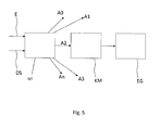
- Fig. 5 shows a power supply arrangement according to the invention with a power supply NT, which receives electrical energy E via a power line, which also provides a modulated data signal DS.
- the inputs for the electrical energy E and the modulated data signal DS are shown by two arrows. Typically, this is physically a single power line.
- the power supply unit NT has several connections A0, A1, A2,..., An.
- a single power outlet can be provided. This is, for example, the power outlet A2.
- These outlets or connections are connected according to the invention to a communication module KM.
- this is shown only for a communication module KM.
- the communication module KM receives now the electrical energy E and provides them to the terminal EC ready.
- the communication module KM is set up to remove the modulated data signal DS of the power line.
- the power supply not only redistributes the energy of the power line, but also passes the modulated data signal to the communication module KM.
- the communication module serves as an intermediate adapter between the power supply NT and the terminal EG.
- This power supply arrangement according to the invention is particularly advantageous because conventional devices can be upgraded with little effort.
- the power supply NT, the communication module KM and the terminal EG are accommodated in a single housing.
- the power supply NT receives the electrical energy and forwards it by means of the communication module KM to the terminal, for example the receiving electronics.
- the power supply unit NT passes the data signal DS to the communication module KM, which now demodulates the data signal DS and forwards packets to the terminal in accordance with an Internet protocol.
- the communication module KM can be present as a switch, or as a converter, which converts data signals DS into data packets.
- the communication module demodulates the data signals DS and provides a certain amount of data or a control information to the terminal.
- the invention also includes individual features in the figures, even if they are shown there in connection with other features and / or not mentioned above.
Landscapes
- Engineering & Computer Science (AREA)
- Power Engineering (AREA)
- Computer Networks & Wireless Communication (AREA)
- Signal Processing (AREA)
- Cable Transmission Systems, Equalization Of Radio And Reduction Of Echo (AREA)
- Small-Scale Networks (AREA)
- Selective Calling Equipment (AREA)
Abstract
Description
- Die vorliegende Erfindung bezieht sich auf das Gebiet der Daten- und Telekommunikation. Im Speziellen betrifft die Erfindung die Übertragung von Nachrichten und Informationen über bestehende elektrische Leitungen in Gebäuden, die ursprünglich zum Zweck der Elektroenergieversorgung konzipiert und installiert wurden sowie die Integration dafür notwendiger Abschluss- und Übertragungseinrichtungen in Endgeräte. Demgemäß lehrt die vorliegende Erfindung eine Netzteilanordnung zum Empfang elektrischer Energie und eines Datensignals mitsamt einer analog ausgestalteten Netzanordnung zum Bereitstellen elektrischer Energie und eines Datensignals. Ferner sind entsprechende Verfahren gezeigt, die zum Betreiben der vorgeschlagenen Vorrichtungen eingerichtet sind.
- Installationen zur Elektroenergieversorgung in Wohnungen und Häusern sind flächendeckend vorhanden und dienen überwiegend ausschließlich entsprechend ihrer ursprünglichen Bestimmung der Verteilung von Elektroenergie an direkt angeschlossene Verbraucher sowie an Steckdosen und daran angeschlossene Verbraucher in Wohnungen, Geschäfts- und anderen Räumen. Darüber hinaus lässt sich diese Infrastruktur auch zur Übertragung von Nachrichten nutzen, zum Beispiel zur Anbindung an das Internet und dazu notwendiger Kommunikation. Dazu wird im Frequenzmultiplex ein weiteres elektronisches Signal auf das Netz zum Beispiel im Hausverteilerkasten aufmoduliert.
- Da eine Vielzahl von Geräten, die auch mit Kommunikationsanbindungen ausgestattet werden, einen 230-V-Anschluss an das Energieversorgungsnetz besitzen, zum Beispiel Radioempfänger, Fernsehgeräte oder Waschmaschinen, und dieser auch meist unverzichtbar ist, ist es vorteilhaft, eine in diesen Anschluss integrierte Kommunikationsanbindung bereitzustellen.
- Bekannt sind in Gebäuden installierte Elektroenergieverteilnetze. Ebenso ist das Prinzip der Powerline Communication PLC, also der Übertragung von Informationen über ein Elektroenergieversorgungsnetz, bekannt.
- Die
DE 101 50 226 C1 zeigt eine Anordnung zum Anschluss einer Powerline-Datenübertragungseinrichtung oder eines Zwischenverstärkers an einen spannungsführenden Verteilerkasten eines Niederspannungs-Stromnetzes, bei der der Verteilerkasten mindestens eine Sammelschiene aufweist. Insbesondere beschreibt diese Druckschrift eine Anordnung mittels derer ganze Straßenzüge oder eine Vielzahl von Wohnungen mittels eines Powerline-Systems ausgestattet werden können. - Die
AU 2009 251 115 A1 - Die
WO 2004/030431 A2 zeigt ein Verfahren und ein System zum Übertragen von Kommunikationssignalen mittels eines Powerline-Systems. Hierbei wird auf die Störfaktoren der Datenleitung eingegangen und die Verwendung mehrerer Verstärker vorgeschlagen. - Die
AU 2000 51 946 A1 - Die
DE 100 08 602 A1 zeigt ein datenverarbeitendes Gerät mit einem Netzteil für eine interne Versorgung mit elektrischer Energie. Die elektrische Energie wird aus einem elektrischen Energieversorgungsnetz gespeist. Gemäß dieser Druckschrift ist eine Rechnerintelligenz notwendig. Das gezeigte datenverarbeitende Gerät weist ein Netzteil auf, das ein Powerline-Kommunikationsmodem bereits integriert hat. Die offenbarte technische Lehre sieht konsequent vor, sowohl eine Rechnerintelligenz als auch ein Modem in ein Netzteil zu integrieren. Hierbei wird eine Rechnerintelligenz durch eine Prozessorenkonfiguration mitsamt zugehöriger Software gebildet. - Bekannt sind weiterhin PLC-Verfahren, die im Frequenzmultiplex eine Ethernet-basierte Kommunikation über das Elektroenergieversorgungsgebäudenetz ermöglichen.
- Dazu wird ein Zusatzmodul, üblicherweise ein Durchgangssteckdosenmodul, verwendet, mit dem man eine Spannung von 220/230 V zur Elektroenergieversorgung an das betreffende Gerät durchleitet. In dem Gerät ist ein Kommunikationsmodul vorgesehen, das das Ethernet-Signal ausgekoppelt, also vor dem Endgerät, zum Beispiel einem Radiogerät, einem Fernsehgerät oder einer Waschmaschine.
-
Fig. 1 zeigt eine Anordnung entsprechend dem Stand der Technik bezüglich eines Einphasen-Wechselstroms als ein Anwendungsszenario der vorliegenden Erfindung. Die Elektroenergie erreicht die Steckdose und damit den angeschlossenen Verbraucher über folgende Instanzen: Aus dem Energieversorgungsnetz EN wird über den Hausanschluss und den Elektrozähler der Hausverteiler erreicht, von dem aus über die im Haus bzw. der Wohnung installierten Leitungen die einzelnen Steckdosen und Verbraucher angeschlossen sind. Das Kommunikationssignal, zum Beispiel zum Breitband-Internet-Anschluss, erreicht aus dem Telekommunikationsnetz T über den Abschlusspunkt der Linientechnik (APL) den Heimnetzknoten, das sogenannte Home Gateway (HGW). Um nun ein Gerät, zum Beispiel einen PC, wie dargestellt an das Telekommunikationsnetz über PLC anschließen zu können, sind meist zwei Umsetzer, bzw. PLC-Adapter, notwendig: Einmal auf der Seite des HGWs, um das Kommunikationssignal geeignet für die PLC-Übertragung aufzubereiten und zum Beispiel in die richtige Frequenzlage umzusetzen, siehe PLC-Adapter 1, und auf der Seite des PCs, um diese Umsetzung wieder rückgängig zu machen und das Signal für den PC in eine geeignete Form zu bringen, siehe PLC-Adapter 2. Alle diese Merkmale des Anwendungsszenarios können mit den erfindungsgemäßen Vorrichtungen zum Bereitstellen oder Versenden von Datensignalen zusammenwirken. - Ein sinngemäßes Bild zum Stand der Technik für eine Ausführung mit DreiphasenWechselstrom zeigt
Fig. 2 als ein Anwendungsszenario der vorliegenden Erfindung. - Bekannte Verfahren und Anordnungen haben den Nachteil, dass diese unnötigerweise mindestens zwei Kabel und diverse Netzwerkkomponenten vorsehen. So wird gemäß herkömmlicher PLC-Verfahren ein Netzteil vorgesehen, welches bereits ein integriertes PLC-Modem aufweist, welches zwischen Steckdose und Endgerät eingesteckt wird. Somit ist es gemäß herkömmlicher Anordnungen nicht möglich, auf kostengünstige Weise PLC-Adapter in ein Endgerät zu integrieren. Zwar zeigt der Stand der Technik integrierte PLC-Adapter, diese sind aber stets derart ausgestaltet, dass typischerweise alle Komponenten in einem einzelnen Gerät integriert sind. Beispielsweise ist es ein Nachteil, ein Netzteil mitsamt einem integrierten Modem bereitzustellen, da hierbei das Netzteil mit der eingebetteten Logik des PLC-Modems unteilbar verbunden ist. So ist es gegenüber dem Stand der Technik besonders wünschenswert, eine Anordnung bereitzustellen, die zwar in ein Endgerät, wie z.B. ein TV-Gerät, integrierbar ist, wobei jedoch das Netzteil von der Datenübertragung derart abgekoppelt ist, dass die einzelnen Komponenten auch austauschbar sind.
- Es ist somit eine Aufgabe der vorliegenden Erfindung, den beschriebenen Stand der Technik derart zu verbessern, dass die zusätzlichen Umsetzer auf der Hausanschlussseite und der Seite der Vielzahl von Geräten nicht als separate Geräte benötigt werden, sondern eine integrierte Lösung geschaffen wird.
- Diese Aufgabe wird erfindungsgemäß durch eine Netzteilanordnung mit den Merkmalen des Patentanspruchs 1 gelöst. Bevorzugte Weiterbildungen sind in den abhängigen Ansprüchen angegeben.
- Demgemäß ist eine Netzteilanordnung zum Empfang elektrischer Energie und eines Datensignals vorgesehen. Hierbei ist das Netzteil eingerichtet zum Empfang elektrischer Energie und eines modulierten Datensignals über eine Stromleitung. Ferner ist ein an das Netzteil gekoppeltes Kommunikationsmodul vorgesehen, welches das auf die Stromleitung modulierte Datensignal demoduliert, wobei das Kommunikationsmodul zwischen dem Netzteil an einem stromabnehmenden Endgerät vorgesehen ist.
- Die vorliegende Erfindung sieht ein Netzteil vor, welches beispielsweise gemäß einem Powerline-Kommunikationsverfahren sowohl elektrische Energie als auch ein Datensignal empfängt. Somit wird eine Trägerfrequenzanlage bereitgestellt, die ein Datensignal, das von dem Netzteil empfangen wird, mittels eines Netzwerkmoduls auf eine bestehende Stromleitung moduliert. Dies kann beispielsweise gemäß einem Funktionsprinzip eines Modems erfolgen. Hierzu kann beispielsweise das Übertragungsverfahren namens "orthogonal frequency-division multiplexing" (OFDM) Anwendung finden. Beispielsweise wird auf der Sendeseite eine Vielzahl von Signalen gleichzeitig auf Trägerfrequenzphasen und -amplituden moduliert. Je nach Übertragungsstandard kann das zur Verfügung stehende Frequenzspektrum dabei in Kanäle aufgeteilt werden, um die Störanfälligkeit zu verringern. Ferner können Fehlerkorrektur- und Interleaving-Verfahren Anwendung finden. Weiter können zur Signalüberbrückung zwischen zwei Phasen sogenannte Phasenkoppler vorgesehen sein.
- Somit kann das beschriebene Netzteil an eine herkömmliche Stromleitung angeschlossen werden. Über die Stromleitung wird ein elektrisches Signal übertragen, das aus dem Energieversorgungssignal (beispielsweise mit 50 Hz) und dem Datensignal bei einer höheren Frequenz (entsprechend PLC-Standard) besteht. Die in dem Datensignal enthaltene Information wird auf eine entsprechende Trägerfrequenz aufmoduliert und dann, wie erwähnt, im Frequenzmultiplex über die Stromleitung übertragen. Das Signal wird nunmehr von dem Netzteil empfangen und an ein Kommunikationsmodul durchgereicht. Das Kommunikationsmodul ist derart an das Netzteil gekoppelt, dass es von dem Netzteil nicht nur durch elektrische Energie bzw. Spannung versorgt wird, sondern dass das Kommunikationsmodul auch das modulierte Datensignal erkennen und demodulieren kann. Somit erfolgt ein Abtrennen des Datensignals vom außerdem auf der Stromleitung übertragenen Energieversorgungssignal. Das Datensignal kann nunmehr an weitere Netzwerkkomponenten bereitgestellt werden. Beispielsweise kann das Datensignal an eine Steuereinheit eines Endgeräts bereitgestellt werden, um somit Funktionen des Endgeräts auszulösen. Somit ist es erfindungsgemäß vorgesehen, neben einer Vielzahl bekannter Anwendungsszenarien, beispielsweise auch ein Datensignal einem beliebigen Haushaltsgerät, z.B. einem Kühlschrank, einer Lampe oder einem Trockner, bereitzustellen.
- Erfindungsgemäß ist es somit möglich, ein Netzteil auszuliefern, an welches das Kommunikationsmodul gekoppelt ist. Hierbei ist es besonders vorteilhaft, dass das Netzteil und das Kommunikationsmodul separat austauschbar sind. Somit wird kein einteilig ausgeformtes Netzteil ausgeliefert, sondern es ist eine Netzteilanordnung vorgesehen, wobei bezüglich eines Netzteils mehrere Varianten, beispielsweise mit unterschiedlichen Wattzahlen, vorgesehen sein können und ferner, hiervon getrennt, diverse Kommunikationsmodule, welche jeweils eine geeignete Steuersoftware aufweisen. Somit ist es erfindungsgemäß möglich, einem Endkunden ein Netzteil mitsamt einem Kommunikationsmodul bereitzustellen, wobei das Kommunikationsmodul je nach Bedarf ausgetauscht werden kann. Liegt beispielsweise das Kommunikationsmodul als eine Weiche vor, so kann auf einfache Weise diese Weiche ausgetauscht werden ohne hierbei das Netzteil wechseln zu müssen. Dennoch ist das Netzteil mitsamt dem Kommunikationsmodul einfach in ein bestehendes Endgerät einzubauen und ist aufgrund der erfindungsgemäßen Anordnung im Inneren eines Endgeräts zu platzieren. Somit entfallen für den Endkunden Netzwerkkomponenten, welche beispielsweise in eine Steckdose eingesteckt werden und das Datensignal dann mittels eines Ethernet-Kabels an das Endgerät bereitstellen.
- Auch ist es erfindungsgemäß möglich, dass das Netzteil mehrere Stromauslässe anbietet, wobei das Kommunikationsmodul lediglich an einen Stromauslass gekoppelt ist. Somit ist es erfindungsgemäß möglich, dass beispielsweise bei einem herkömmlichen Rechner ein Netzteil eingebaut wird, das mehrere Stromanschlüsse bereitstellt, welche mit einem Laufwerk oder einem Motherboard verbunden werden können, und einen separaten Stromauslass, welcher an das Kommunikationsmodul gekoppelt ist. Somit ist es erfindungsgemäß möglich, mittels des Kommunikationsmoduls elektrische Energie durchzuleiten, wobei jedoch das Datensignal abgetrennt und gesondert bereitgestellt wird.
- Gemäß einem Aspekt der vorliegenden Erfindung entspricht das Datensignal einem Ethernet-Standard. Dies hat den Vorteil, dass bestehende Protokolle wieder- bzw. weiterverwendet werden können. Somit ist keine Anpassung weiterer Geräte, welche bisher auch im Ethernet-Standard kommunizieren, notwendig. Bestehende Protokolle und Netzwerkkomponenten können somit auch mit der erfindungsgemäßen Netzteilanordnung kommunizieren.
- Gemäß einem weiteren Aspekt der vorliegenden Erfindung sind das Netzteil, das Kommunikationsmodul und das stromabnehmende Endgerät in einem Gehäuse integriert. Dies bietet den Vorteil, dass die vorliegende Netzteilanordnung mitsamt einem stromabnehmenden Endgerät als ein Produkt ausgeliefert werden kann. Beispielsweise kann ein Gehäuse als ein Radiogehäuse vorliegen, in welches die erfindungsgemäße Netzteilanordnung mitsamt einem Radioempfänger und Kommunikationsschnittstellen integriert ist. Hierbei erkennt der Fachmann diverse weitere Ausgestaltungen eines Gehäuses, beispielsweise das einer Waschmaschine, eines Trockners oder eines Fernsehgeräts.
- Gemäß einem weiteren Aspekt der vorliegenden Erfindung steuert eine Steuereinheit das stromabnehmende Endgerät mittels des Datensignals an. Dies hat den Vorteil, dass beispielsweise eine Steuereinheit, welche bezüglich der Netzteilanordnung extern angeordnet ist, Steuersignale bereits über die Stromleitung an das stromabnehmende Endgerät überträgt. So kann beispielsweise eine Kühlschrankinformation, wie beispielsweise eine Temperatureinstellung, mittels des Stromnetzes an einen Kühlschrank übertragen werden. Hierbei werden netzwerkseitig Kommunikationsprotokolle implementiert, welche das Übertragen von Konfigurationsdaten an das Endgerät ermöglichen.
- Gemäß einem weiteren Aspekt der vorliegenden Erfindung wird die Steuereinheit durch mindestens einen Server gebildet. Dies hat den Vorteil, dass speziell eingerichtete Anbieter Endgeräte, beispielsweise gemäß einem Smart-Home Anwendungsszenario, ansteuern können. Somit können Dienstanbieter eine Steuerungslogik anbieten, die über das Netzwerk auf einfache Weise an die Endgeräte übertragen wird.
- Gemäß einem weiteren Aspekt der vorliegenden Erfindung liegt das Kommunikationsmodul als eine Weiche vor. Dies hat den Vorteil, dass die Netzteilanordnung selbst keine Rechnerintelligenz aufweisen muss, sondern dass lediglich einfach zu implementierende Hardwaremodule Anwendung finden können. Hierbei ist es erfindungsgemäß möglich, dass die Weiche ohne einen Prozessor bzw. eine Steuerungssoftware auskommt. Diese kann beispielsweise als eine speziell eingerichtete Schaltung bereitgestellt werden.
- Gemäß einem weiteren Aspekt der vorliegenden Erfindung liegt das stromabnehmende Endgerät als ein Radio, ein Fernsehgerät, ein Kühlschrank, eine Waschmaschine, ein Trockner, eine Lampe oder als ein Rechner bzw. Computer vor. Dies hat den Vorteil, dass eine Vielzahl von Endgeräten mit der erfindungsgemäßen Netzteilanordnung ausgestattet werden kann.
- Die vorliegende Aufgabe wird ebenfalls gelöst durch eine Netzwerkanordnung zum Bereitstellen elektrischer Energie und eines Datensignals gemäß einem weiteren nebengeordneten Patentanspruch.
- Demgemäß wird eine Netzwerkanordnung zum Bereitstellen elektrischer Energie und eines Datensignals vorgeschlagen, aufweisend eine Energiequelle zum Bereitstellen elektrischer Energie über eine Stromleitung sowie ein an das Netzmodul gekoppeltes Kommunikationsmodul, welches ein Datensignal auf die Stromleitung moduliert, wobei das Kommunikationsmodul zwischen der Energiequelle und einer Mehrzahl an Steckdosen vorgesehen ist.
- Somit ist es möglich, in ein bestehendes Elektroenergieverteilnetz eines Hauses die erfindungsgemäße Netzwerkanordnung derart einzubringen, dass diese für den Endbenutzer nicht sichtbar ist. Dies heißt beispielsweise, dass die Netzwerkanordnung Unterputz derart zwischen der Energiequelle und einer Mehrzahl an Steckdosen installiert werden kann, dass mittels einer geeigneten Schnittstelle des Kommunikationsmoduls sowohl Datensignale als auch elektrische Energie von dem Kommunikationsmodul empfangen werden können. Das Kommunikationsmodul reicht nunmehr die elektrische Energie an die Steckdose durch und moduliert gleichzeitig das empfangene Datensignal auf. Somit wird an einer Mehrzahl von herkömmlichen Steckdosen nicht wie bekannt lediglich Strom bereitgestellt, sondern die Stromleitung, welche die Steckdose versorgt, stellt auch das modulierte Datensignal bereit. Dies ist insbesondere deshalb vorteilhaft, da bereits in einem Verteilerkasten das erfindungsgemäße Kommunikationsmodul derart eingebaut werden kann, dass an allen Steckdosen in einem Haushalt das modulierte Datensignal abgreifbar ist. Somit muss nicht wie in bekannten Verfahren ein externer Adapter an eine herkömmliche Steckdose angeschlossen werden, sondern das Aufmodulieren des Datensignals erfolgt bereits zwischen der Energiequelle und der Mehrzahl an Steckdosen, beispielsweise eines Gebäudes. Somit sind herkömmliche Energieversorgungsnetze eines Gebäudes in einfacher Weise nachrüstbar.
- In die Steckdose wird nunmehr ein Stromkabel eingesteckt, das beispielsweise ein Endgerät mit der erfindungsgemäßen Netzteilanordnung gemäß Patentanspruch 1 versorgt. Somit wird ein moduliertes Datensignal an den Steckdosen bereitgestellt, das mittels lediglich eines Stromkabels an ein stromabnehmendes Endgerät übermittelt wird. Dieses stromabnehmende Endgerät kann nun mittels der erfindungsgemäßen Netzteilanordnung nicht nur lediglich den Strom abgreifen, sondern auch das modulierte Datensignal demodulieren und somit Steuerungsinformationen entnehmen. Dies ist besonders vorteilhaft, da in der gesamten Netzwerkanordnung keinerlei Adapter Verwendung finden müssen, welche erst auf die Steckdose aufgesteckt bzw. einem Endgerät vorgeschaltet werden.
- Gemäß einem Aspekt der vorliegenden Erfindung ist das Kommunikationsmodul mit einem Telekommunikationsnetz verbunden. Dies hat den Vorteil, dass das Kommunikationsmodul nicht nur von der Energiequelle die Energie bereitgestellt bekommt, sondern an einem zentralen Punkt im Netzwerk auch das Datensignal mittels des Telekommunikationsnetzes bereitgestellt bekommt. Das Kommunikationsmodul kann nunmehr das Datensignal auf die Stromleitung aufmodulieren und beispielsweise an alle Steckdosen eines Gebäudes weiterleiten.
- Gemäß einem weiteren Aspekt der vorliegenden Erfindung ist das Kommunikationsmodul an einen Hausverteiler gekoppelt. Dies hat den Vorteil, dass ein bestehendes Energieversorgungsnetz mit wenig Aufwand derart erweitert werden kann, dass an allen Steckdosen des Energieversorgungsnetzwerkes ein moduliertes Datensignal bereitgestellt werden kann.
- Gemäß einem weiteren Aspekt der vorliegenden Erfindung ist das Kommunikationsmodul in einen Verteilerkasten integriert. Dies hat den Vorteil, dass bereits aufgerüstete Verteilerkästen zur Montage bereitgestellt werden können, welche mittels angeschlossener Netzwerktechnik das Datensignal an die Steckdosen bereitstellen kann.
- Gemäß einem Aspekt der vorliegenden Erfindung ist die Mehrzahl an Steckdosen ortsfest in mindestens ein Gebäude eingebracht. Dies hat den Vorteil, dass bestehende Installationen einfach erweitert werden können und die erfindungsgemäße Netzwerkanordnung in einem bestehenden Energieversorgungssystem nachgerüstet werden kann.
- Gemäß einem Aspekt der vorliegenden Erfindung liegt das Kommunikationsmodul als eine Weiche vor. Dies hat den Vorteil, dass die erfindungsgemäße Netzwerkanordnung einfach und Kostengünstig bereitgestellt werden kann, da keine Recheneinheit verbaut werden muss. Zusätzlich minimiert eine einfache Weiche die Fehleranfälligkeit im Vergleich zu bestehenden komplexeren Systemen.
- Die Aufgabe wird ebenfalls gelöst durch ein Verfahren zum Empfangen bzw. zur Aufnahme elektrischer Energie und eines Datensignals, mit dem Schritt Empfangen elektrischer Energie und eines modulierten Datensignals mittels eines Netzteils über eine Stromleitung. Weiterhin ist ein Demodulieren des Datensignals mittels eines an das Netzteil gekoppelten Kommunikationsmoduls vorgesehen, wobei das Kommunikationsmodul zwischen dem Netzteil und einem stromabnehmenden Endgerät vorgesehen ist. Somit ist das vorgeschlagene Verfahren geeignet zum Betreiben der Netzteilanordnung gemäß dem Patentanspruch 1.
- Die Aufgabe wird weiterhin gelöst durch ein Verfahren zum Bereitstellen elektrischer Energie und zum Modulieren eines Datensignals, aufweisend ein Bereitstellen elektrischer Energie über eine Stromleitung mittels einer Energiequelle sowie ein Modulieren einer Datensignals auf die Stromleitung mittels eines an das Netzmodul gekoppelten Kommunikationsmoduls, wobei das Kommunikationsmodul zwischen der Energiequelle und einer Mehrzahl an Steckdosen vorgesehen ist.
- Das mit einer Kommunikationsverbindung zu versorgende Gerät, zum Beispiel Radiogerät, Fernsehgerät, Kühlschrank, Waschmaschine, enthält erfindungsgemäß schon ein Kommunikationsmodul, das bei Anschluss des Geräts an die Steckdose unmittelbar mit angeschlossen wird. Im Gerät ist eine Weiche, die das 220/230-V-Signal und das Kommunikationssignal (Ethernet) trennt. Das Ethernet-Signal wird im Gerät in einem integrierten Kommunikationsmodul verarbeitet, der Nutzer braucht nichts weiter zu tun. Im Verteilerkasten ist beispielsweise ein Master-PLC-Modul vorgesehen, das eine Kommunikationsnetzanbindung aufweist, zum Beispiel über den Heimnetzknoten (HGW). Somit sind erfindungsgemäß alle Stromkreise im Haus für integrierte Powerline-Übertragung vorbereitet und ausgerüstet. Insgesamt erfolgt damit eine Integration der Powerline-Kommunikationstechnik in eine bestehende Kabel- und Stecker-Infrastruktur der Elektroenergie-Versorgungsinstallation.
- Somit wird erfindungsgemäß auf eine stabile, üblicherweise bestehende Festnetzverdrahtung (Haus-/Wohnungs-Energieversorgungsnetz) zurückgegriffen, ohne Extra-Leitungen und Extra-Geräte/-Umsetzer für eine Powerline-Kommunikation zu benötigen, was zu einer Einsparung von PLC-Adaptern führt. Da typischerweise fast jedes Gerät über einen 220/230-V-Anschluss verfügt, ist eine Mitnutzung (inhärent) als Kommunikationsverbindung von großem Wert im Sinne der Vereinfachung der Gesamtinstallation. Man benötigt zum Beispiel keine Extra-Bluetooth-, ZigBee, Z-Wave oder WLAN-Verbindung oder ein Extra-LAN-Kabel zur Kommunikationsanbindung von Geräten, die über eine Anbindung an die Elektroenergieinstallation im Haus bzw. in einer Wohnung über zum Beispiel einen Steckdose verfügen. Es wird erfindungsgemäß kein WLAN, Bluetooth, ZigBee, usw. für Datennetzanbindung benötigt. Dies ist insbesondere auch dann von Wert, wenn der Nutzer keine Funksignale in seiner Umgebung möchte (WLAN, Bluetooth) bzw. deren Einfluss minimieren möchte und außerdem kein zusätzliches Ethernetkabel verlegt werden soll oder kann.
- Zudem kann ein integriertes Sicherheitskonzept mittels der erfindungsgemäßen Lösung konstruiert werden, bei dem eine gesicherte Kommunikation nur mit einem Rechenzentrum etabliert wird und von dort eine sichere Verbindung, zum Beispiel IPSec-Tunnel, zu Drittanbieter des betreffenden Gerätes, zum Beispiel eines Kühlschranks, aufgebaut wird. Auch die Steuerung weiterer Geräte und Aktoren im Haus, zum Beispiel Lampen, ist ohne Funkverbindung (WLAN, Bluetooth, Z-Wave, ZigBee) möglich, was die Nutzung der erfindungsgemäßen Lösung im Smart Home Umfeld wesentlich erleichtert. Jedes Gerät, das einen 230-V-Anschluss hat, kann kommunizieren oder gesteuert werden.
- Die erfindungsgemäße Anordnung und Lösung erfordert lediglich gemäß einem Aspekt der vorliegenden Erfindung eine zentrales Master PLC Modul, das vorzugsweise im Strom-Verteilerkasten eines Hauses oder Gebäudes untergebracht ist. Dieses sollte nach DIN EN60715 (alt: DIN EN 50022 ... 50024, DIN EN 50035 und DIN EN 50045; DIN-Hutschiene oder Tragschiene (DIN-Rail)) auf der Hutschiene des Verteilerkastens untergebracht werden und mit allen im Haus oder Gebäude verwendeten Phasen (1P oder 3P) verbunden sein, um die entsprechenden PLC-Modulationsdaten auf allen Phasen übertragen zu können, ggf. mit Phasenkoppler. Dabei unterstützt das Master-PLC-Modul zur Kommunikation mit den Geräten im Haushalt oder in Gebäuden lediglich gemäß einem Aspekt der vorliegenden Erfindung alle bekannten und standardisierten Trägerfrequenzverfahren, zum Beispiel PowerLAN, dLAN, Homeplug, Homeplug Turbo, Homeplug AV, IEEE 1901.2 Low-Frequency, Narrow-Band Powerline Communications.
- Auf der netzseitigen Kommunikation kommt lediglich gemäß einem Aspekt der vorliegenden Erfindung Ethernet nach IEEE 802.3, z.B. Fast Ethernet, Gigabit Ethernet, zum Einsatz. Das Master PLC Modul wird damit direkt mit dem Home Gateway (DSL-Router, Kabel-Modem, Glasfaser-ONT) verbunden und erhält somit über die Anbindung an das Telekommunikationsnetz des jeweiligen Anbieters die Möglichkeit der weltweiten Kommunikation. Möglich ist auch die Platzierung (Integration) des Master PLC Moduls direkt im HGW. Bei 3-Phasen-Wechselstrom ist lediglich gemäß einem Aspekt der vorliegenden Erfindung ein Phasenkoppler zur Verbesserung der Übertragung auf alle Phasen im Verteilerkasten der Hausstromverkabelung vorzusehen.
- Diese Lösung gemäß der vorliegenden Erfindung funktioniert damit ohne die üblichen Adapter (Modems) zur Einspeisung bzw. Einkopplung und Auskopplung der Daten auf/aus den Stromleitungen des Hauses oder Gebäudes.
- Die Erfindung wird nunmehr anhand beispielhafter Ausgestaltungen beschrieben. Es zeigen:
- Fig. 1
- ein Anwendungsszenario der vorliegenden Erfindung gemäß dem Stand der Technik mit einem 1-Phasen-Wechselstrom;
- Fig. 2
- ein weiteres Anwendungsszenario der vorliegenden Erfindung gemäß dem Stand der Technik mit einem 3-Phasen-Wechselstrom;
- Fig. 3
- eine schematische Darstellung eines Master-PLC-Adapters in einem Hausanschluss gemäß einem Aspekt der vorliegenden Erfindung;
- Fig. 4
- eine schematische Darstellung eines Master-PLC-Adapters in einem Home Gateway gemäß einem Aspekt der vorliegenden Erfindung; und
- Fig. 5
- eine vorteilhafte Netzteilanordnung gemäß einem Aspekt der vorliegenden Erfindung.
-
Figuren 1 und2 zeigen Anwendungsszenarien der vorliegenden Erfindung und wurden bereits beschrieben. - Die erfindungsgemäße Anordnung wird anhand mehrerer Ausführungsbeispiele im Folgenden detailliert erklärt. Als Anwendungsmöglichkeiten sind erfindungsgemäß u. a. folgende Szenarien möglich:
- Steuerung der Helligkeit von Leuchten (niedrige Bitrate)
- Übertragung von Kühlschrankinhaltsinformationen an Lieferdienste
- Datennetzanbindung für Kommunikationsgeräte, zum Beispiel PC, Fernsehgerät (hohe Bitrate)
- Direkter Kommunikationsanschluss für Internetradio
- Steuerung von Haushaltsgeräten, zum Beispiel Waschmaschine, Trockner
- Steuerung von (einem Energieversorgungsunternehmen aus der Ferne über gesicherte Verbindungen) zum Beispiel von Wärmepumpen und Photovoltaik-Anlagen zur Nutzung von Strompreisunterschieden bzw. Stabilisierung des Stromnetzes (Ausregeln von Angebot und Nachfrage bei dezentraler Einspeisung und Verbrauch)
- In einem weiteren Ausführungsbeispiel ist ein Master-PLC-Modul im Hausanschluss vorgesehen.
Fig. 3 zeigt schematisch eine Anordnung und damit das Wirkprinzip gemäß der vorliegenden Erfindung: Es ist nun im Hausverteiler ein PLC-Adapter eingefügt ("Master-PLC-Adapter"). Dieser ist lediglich gemäß einem Aspekt der vorliegenden Erfindung so ausgeführt, dass er das gesamte Hausinstallationsnetz mit Kommunikationssignalen versorgt, da alle Steckdosen damit verbunden sind. Seinerseits benötigt dieser eine Datennetzanbindung. Diese ist in diesem Ausführungsbeispiel über ein Ethernet-LAN-Kabel realisiert. Der Verbraucher, hier ein PC, ist über das Elektroverteilnetz angeschlossen. Über diesen wird es mit Elektroenergie und (über PLC) mit dem Kommunikationssignal versorgt. Um beide Signale zu trennen, ist im Gerät (PC) ein PLC-Adapter integriert, der das Kommunikationssignal in ein für den PC geeignetes Format umsetzt. - In einem weiteren Ausführungsbeispiel ist ein Master-PLC-Modul in einem Home Gateway vorgesehen.
-
Fig. 4 zeigt schematisch eine weitere Anordnung entsprechend des Wirkprinzips der vorliegenden Erfindung: Es ist nun der Master-PLC-Modul in das Home Gateway integriert. Da das Home Gateway über einen Stromanschluss zum Hauselektroenergieverteilnetz hin verfügt, kann nun diese Verbindung mit als Kommunikationsverbindung genutzt werden. Die Anbindung des Master-PLC-Adapters kann über ein zusätzliches Ethernet-LAN-Kabel entfallen. Die Anordnung und Verarbeitung auf der Geräteseite (im Beispiel der PC) bleibt wie in anderen Ausführungsbeispielen. - Die vorliegende Erfindung kann sowohl für Ein- als auch für Dreiphasenwechselstrom (ggf. mit Phasenkoppler) genutzt werden.
-
Fig. 5 zeigt eine erfindungsgemäße Netzteilanordnung mit einem Netzteil NT, welches elektrische Energie E über eine Stromleitung empfängt, die ebenfalls ein aufmoduliertes Datensignal DS bereitstellt. In der vorliegendenFig. 5 sind die Eingänge für die elektrische Energie E und das modulierte Datensignal DS mittels zweier Pfeile gezeigt. Typischerweise handelt es sich hierbei physisch um eine einzige Stromleitung. Optional weist das Netzteil NT mehrere Anschlüsse A0, A1, A2, ..., An auf. - In einer weiteren erfindungsgemäßen Ausgestaltung kann jedoch auch nur ein einziger Stromauslass vorgesehen sein. Dies ist beispielsweise der Stromauslass A2. Diese Auslasse bzw. Anschlüsse sind erfindungsgemäß mit einem Kommunikationsmodul KM verbunden. In der vorliegenden
Fig. 5 ist dies lediglich für ein Kommunikationsmodul KM gezeigt. Es ist jedoch hierbei auch möglich, an die weiteren Anschlüsse A0 und A1 ebenfalls ein weiteres Kommunikationsmodul KM anzuschließen. Das Kommunikationsmodul KM empfängt nunmehr die elektrische Energie E und stellt sie dem Endgerät EG bereit. Hierbei ist das Kommunikationsmodul KM eingerichtet, das modulierte Datensignal DS der Stromleitung zu entnehmen. Hierzu kann es notwendig sein, dass das Netzteil nicht nur die Energie der Stromleitung weiterverteilt, sondern auch das aufmodulierte Datensignal an das Kommunikationsmodul KM durch leitet. Somit dient das Kommunikationsmodul als ein Zwischenadapter zwischen dem Netzteil NT und dem Endgerät EG. - Diese erfindungsgemäße Netzteilanordnung ist besonders vorteilhaft, da herkömmliche Geräte mit wenig Aufwand aufgerüstet werden können. So ist es beispielsweise möglich, ein herkömmliches Netzteil NT zu verwenden und dies mit dem erfindungsgemäßen Kommunikationsmodul auszurüsten und eben dieses Kommunikationsmodul KM zwischen dem Netzteil NT und dem Endgerät NG vorzusehen. Gemäß einem weiteren Beispiel ist es möglich, dass das Netzteil NT, das Kommunikationsmodul KM und das Endgerät EG in einem einzigen Gehäuse untergebracht sind. Somit ist es erfindungsgemäß möglich, ein Gerät bereitzustellen, welches bereits mit der erfindungsgemäßen Netzteilanordnung ausgestattet ist. So kann das in
Fig. 5 gezeigte Netzteil NT, das Kommunikationsmodul KM und das Endgerät EG das Innenleben eines Radios darstellen, wobei das Endgerät ein Radioempfänger mitsamt Benutzerschnittstelle ist. Somit kann mittels einer Stromleitung nicht nur elektrische Energie E, sondern auch ein Musikstreaming in Form eines Datensignals DS an das Radio bereitgestellt werden. Hierzu empfängt das Netzteil NT die elektrische Energie und leitet sie mittels des Kommunikationsmoduls KM an das Endgerät, beispielsweise die Empfangselektronik, weiter. Außerdem reicht das Netzteil NT das Datensignal DS an das Kommunikationsmodul KM durch, welches nunmehr das Datensignal DS demoduliert und Pakete gemäß einem Internetprotokoll an das Endgerät weiterreicht. Generell kann das Kommunikationsmodul KM als eine Weiche vorliegen, oder als ein Wandler, der Datensignale DS in Datenpakete umwandelt. Somit demoduliert das Kommunikationsmodul die Datensignale DS und stellt eine bestimmte Datenmenge bzw. eine Steuerungsinformation an das Endgerät bereit. - Obwohl die Erfindung mittels der Figuren und der zugehörigen Beschreibung dargestellt und detailliert beschrieben ist, sind diese Darstellung und diese detaillierte Beschreibung illustrativ und beispielhaft zu verstehen und nicht als die Erfindung einschränkend. Es versteht sich, dass Fachleute Änderungen und Abwandlungen machen können, ohne den Umfang der folgenden Ansprüche zu verlassen. Insbesondere umfasst die Erfindung ebenfalls Ausführungsformen mit jeglicher Kombination von Merkmalen, die vorstehend zu verschiedenen Aspekten und/oder Ausführungsformen genannt oder gezeigt sind.
- Die Erfindung umfasst ebenfalls einzelne Merkmale in den Figuren auch wenn sie dort im Zusammenhang mit anderen Merkmalen gezeigt sind und/oder vorstehend nicht genannt sind.
- Im Weiteren schließt der Ausdruck "umfassen" und Ableitungen davon andere Elemente oder Schritte nicht aus. Ebenfalls schließt der unbestimmte Artikel "ein" bzw. "eine" und Ableitungen davon eine Vielzahl nicht aus. Die Funktionen mehrerer in den Ansprüchen aufgeführter Merkmale können durch eine Einheit erfüllt sein. Die Begriffe "im Wesentlichen", "etwa", "ungefähr" und dergleichen in Verbindung mit einer Eigenschaft beziehungsweise einem Wert definieren insbesondere auch genau die Eigenschaft beziehungsweise genau den Wert. Alle Bezugszeichen in den Ansprüchen sind nicht als den Umfang der Ansprüche einschränkend zu verstehen.
Claims (15)
- Netzteilanordnung zur Aufnahme elektrischer Energie (E) und zum Demodulieren eines Datensignals (DS), aufweisend:ein Netzteil (NT) zum Empfang elektrischer Energie (E) und eines modulierten Datensignals (DS) mittels einer Stromleitung; undein an das Netzteil (NT) gekoppeltes Kommunikationsmodul (KM), welches das auf die Stromleitung modulierte Datensignal (DS) demoduliert, wobei das Kommunikationsmodul (KM) zwischen dem Netzteil (NT) und einem stromabnehmenden Endgerät (EG) vorgesehen ist.
- Netzteilanordnung nach Anspruch 1, wobei das Datensignal (DS) einem Ethernet Standard entspricht.
- Netzteilanordnung nach einem der Ansprüche 1 oder 2, wobei das Netzteil (NT), das Kommunikationsmodul (KM), und das stromabnehmende Endgerät (EG) in einem Gehäuse integriert sind.
- Netzteilanordnung nach einem der vorherigen Ansprüche, wobei eine Steuereinheit das stromabnehmende Endgerät (EG) mittels des Datensignals (DS) ansteuert.
- Netzteilanordnung nach Anspruch 4, wobei die Steuereinheit durch mindestens einen Server gebildet wird.
- Netzteilanordnung nach einem der vorherigen Ansprüche, wobei das Kommunikationsmodul (KM) als eine Weiche vorliegt.
- Netzteilanordnung nach einem der vorherigen Ansprüche, wobei das stromabnehmende Endgerät (EG) als ein Element aus einer Gruppe von Endgeräten (EG) vorliegt, die Gruppe aufweisend: ein Radio, ein Fernsehgerät, einen Kühlschrank, eine Waschmaschine, einen Trockner, eine Lampe und einen Rechner, Wärmepumpe, Heizung, elektrische Rollläden.
- Netzwerkanordnung zum Bereitstellen elektrischer Energie (E) und eines Datensignals (DS), aufweisend:Eine Energiequelle zum Bereitstellen elektrischer Energie (E) über eine Stromleitung; undein an das Netzmodul gekoppeltes Kommunikationsmodul (KM), das ein Datensignal (DS) auf die Stromleitung moduliert, wobei das Kommunikationsmodul (KM) zwischen der Energiequelle und einer Mehrzahl an Steckdosen vorgesehen ist.
- Netzwerkanordnung nach Anspruch 8, wobei das Kommunikationsmodul (KM) mit einem Telekommunikationsnetz (T) verbunden ist.
- Netzwerkanordnung nach einem der Ansprüche 8 oder 9, wobei das Kommunikationsmodul (KM) an einen Hausverteiler gekoppelt ist.
- Netzwerkanordnung nach einem der Ansprüche 8 bis 10, wobei das Kommunikationsmodul (KM) in einen Verteilerkasten integriert ist.
- Netzwerkanordnung nach einem der Ansprüche 8 bis 11, wobei die Mehrzahl an Steckdosen ortsfest in mindestens ein Gebäude eingebracht ist.
- Netzwerkanordnung nach einem der Ansprüche 8 bis 12, wobei das Kommunikationsmodul (KM) als eine Weiche vorliegt.
- Verfahren zur Aufnahme elektrischer Energie (E) und zum Demodulieren eines Datensignals (DS), aufweisend:Empfangen elektrischer Energie (E) und eines modulierten Datensignals (DS) mittels eines Netzteils und einer Stromleitung; undDemodulieren des Datensignals (DS) mittels eines an das Netzteil gekoppelten Kommunikationsmoduls (KM), wobei das Kommunikationsmodul zwischen dem Netzteil und einem stromabnehmenden Endgerät (EG) vorgesehen ist.
- Verfahren zum Bereitstellen elektrischer Energie (E) und zum Modulieren eines Datensignals (DS), aufweisend:Bereitstellen elektrischer Energie (E) über eine Stromleitung mittels einer Energiequelle; undModulieren eines Datensignals (DS) auf die Stromleitung mittels eines an das Netzmodul gekoppelten Kommunikationsmoduls (KM), wobei das Kommunikationsmodul (KM) zwischen der Energiequelle und einer Mehrzahl an Steckdosen vorgesehen ist.
Priority Applications (1)
| Application Number | Priority Date | Filing Date | Title |
|---|---|---|---|
| EP15165220.3A EP3089372B1 (de) | 2015-04-27 | 2015-04-27 | Anordnung und verfahren zur integrierten übertragung von nachrichten über elektroenergieversorgungsnetze |
Applications Claiming Priority (1)
| Application Number | Priority Date | Filing Date | Title |
|---|---|---|---|
| EP15165220.3A EP3089372B1 (de) | 2015-04-27 | 2015-04-27 | Anordnung und verfahren zur integrierten übertragung von nachrichten über elektroenergieversorgungsnetze |
Publications (2)
| Publication Number | Publication Date |
|---|---|
| EP3089372A1 true EP3089372A1 (de) | 2016-11-02 |
| EP3089372B1 EP3089372B1 (de) | 2019-06-12 |
Family
ID=53015600
Family Applications (1)
| Application Number | Title | Priority Date | Filing Date |
|---|---|---|---|
| EP15165220.3A Active EP3089372B1 (de) | 2015-04-27 | 2015-04-27 | Anordnung und verfahren zur integrierten übertragung von nachrichten über elektroenergieversorgungsnetze |
Country Status (1)
| Country | Link |
|---|---|
| EP (1) | EP3089372B1 (de) |
Cited By (1)
| Publication number | Priority date | Publication date | Assignee | Title |
|---|---|---|---|---|
| CN107948335A (zh) * | 2018-01-09 | 2018-04-20 | 广东工业大学 | 一种物联网系统 |
Citations (9)
| Publication number | Priority date | Publication date | Assignee | Title |
|---|---|---|---|---|
| AU5194600A (en) | 1996-11-01 | 2000-10-26 | Foster-Miller Inc. | Non-invasive powerline communications system |
| DE10008602A1 (de) | 2000-02-24 | 2001-06-07 | Siemens Ag | Datenverarbeitendes Gerät mit Netzteil und Netzteil für datenverarbeitende Geräte |
| WO2002089353A1 (de) * | 2001-04-26 | 2002-11-07 | Power Plus Communications Ag | Anschluss eines modems als einspeisemöglichkeit für daten bei der leitungsgebundenen datenübertragung an einer verteilervorrichtung |
| DE10150226C1 (de) | 2001-10-12 | 2003-04-30 | Power Plus Communications Ag | Anordnung zum Anschluss einer Powerline-Datenübertragungseinrichtung oder eines Zwischenverstärkers an ein Spannungsführendes Niederspannungs-Stromnetz |
| WO2004030431A2 (en) | 2002-10-02 | 2004-04-15 | Amperion, Inc. | Method and system for signal repeating in powerline communications |
| WO2005046078A2 (en) * | 2003-11-11 | 2005-05-19 | Sumitomo Electric Industries, Ltd. | Communication system |
| AU2009251115A1 (en) | 2004-12-15 | 2010-01-21 | Smartlabs, Inc. | Mesh Network of intelligent devices communicating via powerline and radio frequency |
| EP2341636A2 (de) * | 2009-12-29 | 2011-07-06 | Coppergate Communication Ltd. | Computernetzteil mit Netzbetriebfunktionen |
| EP2464027A1 (de) * | 2009-08-06 | 2012-06-13 | Sumitomo Electric Industries, Ltd. | Stromleitungs-kommunikationsvorrichtung, stromversorgungsschaltung mit kommunikationsfunktion, elektrische anwendung sowie steuerungs- und überwachungssystem dafür |
-
2015
- 2015-04-27 EP EP15165220.3A patent/EP3089372B1/de active Active
Patent Citations (9)
| Publication number | Priority date | Publication date | Assignee | Title |
|---|---|---|---|---|
| AU5194600A (en) | 1996-11-01 | 2000-10-26 | Foster-Miller Inc. | Non-invasive powerline communications system |
| DE10008602A1 (de) | 2000-02-24 | 2001-06-07 | Siemens Ag | Datenverarbeitendes Gerät mit Netzteil und Netzteil für datenverarbeitende Geräte |
| WO2002089353A1 (de) * | 2001-04-26 | 2002-11-07 | Power Plus Communications Ag | Anschluss eines modems als einspeisemöglichkeit für daten bei der leitungsgebundenen datenübertragung an einer verteilervorrichtung |
| DE10150226C1 (de) | 2001-10-12 | 2003-04-30 | Power Plus Communications Ag | Anordnung zum Anschluss einer Powerline-Datenübertragungseinrichtung oder eines Zwischenverstärkers an ein Spannungsführendes Niederspannungs-Stromnetz |
| WO2004030431A2 (en) | 2002-10-02 | 2004-04-15 | Amperion, Inc. | Method and system for signal repeating in powerline communications |
| WO2005046078A2 (en) * | 2003-11-11 | 2005-05-19 | Sumitomo Electric Industries, Ltd. | Communication system |
| AU2009251115A1 (en) | 2004-12-15 | 2010-01-21 | Smartlabs, Inc. | Mesh Network of intelligent devices communicating via powerline and radio frequency |
| EP2464027A1 (de) * | 2009-08-06 | 2012-06-13 | Sumitomo Electric Industries, Ltd. | Stromleitungs-kommunikationsvorrichtung, stromversorgungsschaltung mit kommunikationsfunktion, elektrische anwendung sowie steuerungs- und überwachungssystem dafür |
| EP2341636A2 (de) * | 2009-12-29 | 2011-07-06 | Coppergate Communication Ltd. | Computernetzteil mit Netzbetriebfunktionen |
Cited By (1)
| Publication number | Priority date | Publication date | Assignee | Title |
|---|---|---|---|---|
| CN107948335A (zh) * | 2018-01-09 | 2018-04-20 | 广东工业大学 | 一种物联网系统 |
Also Published As
| Publication number | Publication date |
|---|---|
| EP3089372B1 (de) | 2019-06-12 |
Similar Documents
| Publication | Publication Date | Title |
|---|---|---|
| US20070008074A1 (en) | Multi-subnet power line communications system and method | |
| US20040113756A1 (en) | Device and method for coupling with electrical distribution network infrastructure to provide communications | |
| SE1000953A1 (sv) | Signal repeater system arrangemang för stabil data kommunikation | |
| CA2505429A1 (en) | A power line communication system and method of using the same | |
| WO2001043238A1 (de) | Anordnung zur übermittlung von nachrichten über ein niederspannungs-stromversorgungsnetz | |
| US10571297B2 (en) | Meter collar system for powerline communication | |
| EP3879944B1 (de) | Lichtband mit zusätzlicher datenleitung | |
| DE102010029219A1 (de) | Datenübertragungseinrichtung | |
| EP3089372B1 (de) | Anordnung und verfahren zur integrierten übertragung von nachrichten über elektroenergieversorgungsnetze | |
| DE102014200464A1 (de) | Vorrichtung und Verfahren zum kombinierten Betreiben eines elektrischen Verbrauchers mit Netzstrom und/oder elektrischer Energie aus einer unabhängigen Energiequelle | |
| EP1147443B1 (de) | Kombination aus einem netzstecker und einem digitalen datenstecker | |
| DE102016119409A1 (de) | Kommunikationssystem | |
| EP1488487A1 (de) | Heim- und gebäudeinformationssystem | |
| CN209313857U (zh) | 一种带PoE功能的同轴线以太网桥 | |
| EP4071933B1 (de) | Modulare multifunktionssteckdose | |
| EP2206412B1 (de) | Verfahren und system zur ansteuerung und energieversorgung von mindestens einem elektrischen verbraucher | |
| DE102008009542B4 (de) | Netzteil mit Datenschnittstelle | |
| WO2019175028A1 (de) | Stromschienensystem und stromschienenanordnung zur datenübertragung | |
| EP1429495B1 (de) | Busfähige Anschluss- und Steuerungseinrichtung für einen dezentralen Einsatz in Niederspannungs-Verbraucheranlagen | |
| WO2001067630A1 (de) | Ankopplung einer kopfstation an ein niederspannungs-stromversorgungsnetz | |
| CN206506542U (zh) | 家庭宽带组网系统 | |
| DE212007000099U1 (de) | Kombinierbare Multimedia-Verlängerungssteckdose | |
| DE202005021023U1 (de) | Gebäudeinstallationssystem | |
| Koch | Power line communications and hybrid systems for home networks | |
| EP4629455A1 (de) | Hausstromunterverteiler |
Legal Events
| Date | Code | Title | Description |
|---|---|---|---|
| PUAI | Public reference made under article 153(3) epc to a published international application that has entered the european phase |
Free format text: ORIGINAL CODE: 0009012 |
|
| AK | Designated contracting states |
Kind code of ref document: A1 Designated state(s): AL AT BE BG CH CY CZ DE DK EE ES FI FR GB GR HR HU IE IS IT LI LT LU LV MC MK MT NL NO PL PT RO RS SE SI SK SM TR |
|
| AX | Request for extension of the european patent |
Extension state: BA ME |
|
| STAA | Information on the status of an ep patent application or granted ep patent |
Free format text: STATUS: REQUEST FOR EXAMINATION WAS MADE |
|
| 17P | Request for examination filed |
Effective date: 20170502 |
|
| RBV | Designated contracting states (corrected) |
Designated state(s): AL AT BE BG CH CY CZ DE DK EE ES FI FR GB GR HR HU IE IS IT LI LT LU LV MC MK MT NL NO PL PT RO RS SE SI SK SM TR |
|
| STAA | Information on the status of an ep patent application or granted ep patent |
Free format text: STATUS: EXAMINATION IS IN PROGRESS |
|
| 17Q | First examination report despatched |
Effective date: 20170816 |
|
| GRAP | Despatch of communication of intention to grant a patent |
Free format text: ORIGINAL CODE: EPIDOSNIGR1 |
|
| STAA | Information on the status of an ep patent application or granted ep patent |
Free format text: STATUS: GRANT OF PATENT IS INTENDED |
|
| INTG | Intention to grant announced |
Effective date: 20181221 |
|
| GRAS | Grant fee paid |
Free format text: ORIGINAL CODE: EPIDOSNIGR3 |
|
| GRAJ | Information related to disapproval of communication of intention to grant by the applicant or resumption of examination proceedings by the epo deleted |
Free format text: ORIGINAL CODE: EPIDOSDIGR1 |
|
| GRAL | Information related to payment of fee for publishing/printing deleted |
Free format text: ORIGINAL CODE: EPIDOSDIGR3 |
|
| STAA | Information on the status of an ep patent application or granted ep patent |
Free format text: STATUS: EXAMINATION IS IN PROGRESS |
|
| INTC | Intention to grant announced (deleted) | ||
| GRAR | Information related to intention to grant a patent recorded |
Free format text: ORIGINAL CODE: EPIDOSNIGR71 |
|
| STAA | Information on the status of an ep patent application or granted ep patent |
Free format text: STATUS: GRANT OF PATENT IS INTENDED |
|
| GRAA | (expected) grant |
Free format text: ORIGINAL CODE: 0009210 |
|
| STAA | Information on the status of an ep patent application or granted ep patent |
Free format text: STATUS: THE PATENT HAS BEEN GRANTED |
|
| REG | Reference to a national code |
Ref country code: DE Ref legal event code: R082 Ref document number: 502015009281 Country of ref document: DE |
|
| INTG | Intention to grant announced |
Effective date: 20190502 |
|
| AK | Designated contracting states |
Kind code of ref document: B1 Designated state(s): AL AT BE BG CH CY CZ DE DK EE ES FI FR GB GR HR HU IE IS IT LI LT LU LV MC MK MT NL NO PL PT RO RS SE SI SK SM TR |
|
| REG | Reference to a national code |
Ref country code: GB Ref legal event code: FG4D Free format text: NOT ENGLISH |
|
| REG | Reference to a national code |
Ref country code: CH Ref legal event code: EP |
|
| REG | Reference to a national code |
Ref country code: AT Ref legal event code: REF Ref document number: 1143927 Country of ref document: AT Kind code of ref document: T Effective date: 20190615 |
|
| REG | Reference to a national code |
Ref country code: IE Ref legal event code: FG4D Free format text: LANGUAGE OF EP DOCUMENT: GERMAN |
|
| REG | Reference to a national code |
Ref country code: DE Ref legal event code: R096 Ref document number: 502015009281 Country of ref document: DE |
|
| REG | Reference to a national code |
Ref country code: NL Ref legal event code: MP Effective date: 20190612 |
|
| REG | Reference to a national code |
Ref country code: LT Ref legal event code: MG4D |
|
| PG25 | Lapsed in a contracting state [announced via postgrant information from national office to epo] |
Ref country code: FI Free format text: LAPSE BECAUSE OF FAILURE TO SUBMIT A TRANSLATION OF THE DESCRIPTION OR TO PAY THE FEE WITHIN THE PRESCRIBED TIME-LIMIT Effective date: 20190612 Ref country code: NO Free format text: LAPSE BECAUSE OF FAILURE TO SUBMIT A TRANSLATION OF THE DESCRIPTION OR TO PAY THE FEE WITHIN THE PRESCRIBED TIME-LIMIT Effective date: 20190912 Ref country code: LT Free format text: LAPSE BECAUSE OF FAILURE TO SUBMIT A TRANSLATION OF THE DESCRIPTION OR TO PAY THE FEE WITHIN THE PRESCRIBED TIME-LIMIT Effective date: 20190612 Ref country code: HR Free format text: LAPSE BECAUSE OF FAILURE TO SUBMIT A TRANSLATION OF THE DESCRIPTION OR TO PAY THE FEE WITHIN THE PRESCRIBED TIME-LIMIT Effective date: 20190612 Ref country code: AL Free format text: LAPSE BECAUSE OF FAILURE TO SUBMIT A TRANSLATION OF THE DESCRIPTION OR TO PAY THE FEE WITHIN THE PRESCRIBED TIME-LIMIT Effective date: 20190612 Ref country code: SE Free format text: LAPSE BECAUSE OF FAILURE TO SUBMIT A TRANSLATION OF THE DESCRIPTION OR TO PAY THE FEE WITHIN THE PRESCRIBED TIME-LIMIT Effective date: 20190612 |
|
| PG25 | Lapsed in a contracting state [announced via postgrant information from national office to epo] |
Ref country code: LV Free format text: LAPSE BECAUSE OF FAILURE TO SUBMIT A TRANSLATION OF THE DESCRIPTION OR TO PAY THE FEE WITHIN THE PRESCRIBED TIME-LIMIT Effective date: 20190612 Ref country code: GR Free format text: LAPSE BECAUSE OF FAILURE TO SUBMIT A TRANSLATION OF THE DESCRIPTION OR TO PAY THE FEE WITHIN THE PRESCRIBED TIME-LIMIT Effective date: 20190913 Ref country code: RS Free format text: LAPSE BECAUSE OF FAILURE TO SUBMIT A TRANSLATION OF THE DESCRIPTION OR TO PAY THE FEE WITHIN THE PRESCRIBED TIME-LIMIT Effective date: 20190612 Ref country code: BG Free format text: LAPSE BECAUSE OF FAILURE TO SUBMIT A TRANSLATION OF THE DESCRIPTION OR TO PAY THE FEE WITHIN THE PRESCRIBED TIME-LIMIT Effective date: 20190912 |
|
| PG25 | Lapsed in a contracting state [announced via postgrant information from national office to epo] |
Ref country code: CZ Free format text: LAPSE BECAUSE OF FAILURE TO SUBMIT A TRANSLATION OF THE DESCRIPTION OR TO PAY THE FEE WITHIN THE PRESCRIBED TIME-LIMIT Effective date: 20190612 Ref country code: RO Free format text: LAPSE BECAUSE OF FAILURE TO SUBMIT A TRANSLATION OF THE DESCRIPTION OR TO PAY THE FEE WITHIN THE PRESCRIBED TIME-LIMIT Effective date: 20190612 Ref country code: PT Free format text: LAPSE BECAUSE OF FAILURE TO SUBMIT A TRANSLATION OF THE DESCRIPTION OR TO PAY THE FEE WITHIN THE PRESCRIBED TIME-LIMIT Effective date: 20191014 Ref country code: SK Free format text: LAPSE BECAUSE OF FAILURE TO SUBMIT A TRANSLATION OF THE DESCRIPTION OR TO PAY THE FEE WITHIN THE PRESCRIBED TIME-LIMIT Effective date: 20190612 Ref country code: NL Free format text: LAPSE BECAUSE OF FAILURE TO SUBMIT A TRANSLATION OF THE DESCRIPTION OR TO PAY THE FEE WITHIN THE PRESCRIBED TIME-LIMIT Effective date: 20190612 Ref country code: EE Free format text: LAPSE BECAUSE OF FAILURE TO SUBMIT A TRANSLATION OF THE DESCRIPTION OR TO PAY THE FEE WITHIN THE PRESCRIBED TIME-LIMIT Effective date: 20190612 |
|
| PG25 | Lapsed in a contracting state [announced via postgrant information from national office to epo] |
Ref country code: IT Free format text: LAPSE BECAUSE OF FAILURE TO SUBMIT A TRANSLATION OF THE DESCRIPTION OR TO PAY THE FEE WITHIN THE PRESCRIBED TIME-LIMIT Effective date: 20190612 Ref country code: ES Free format text: LAPSE BECAUSE OF FAILURE TO SUBMIT A TRANSLATION OF THE DESCRIPTION OR TO PAY THE FEE WITHIN THE PRESCRIBED TIME-LIMIT Effective date: 20190612 Ref country code: SM Free format text: LAPSE BECAUSE OF FAILURE TO SUBMIT A TRANSLATION OF THE DESCRIPTION OR TO PAY THE FEE WITHIN THE PRESCRIBED TIME-LIMIT Effective date: 20190612 Ref country code: IS Free format text: LAPSE BECAUSE OF FAILURE TO SUBMIT A TRANSLATION OF THE DESCRIPTION OR TO PAY THE FEE WITHIN THE PRESCRIBED TIME-LIMIT Effective date: 20191012 |
|
| REG | Reference to a national code |
Ref country code: DE Ref legal event code: R097 Ref document number: 502015009281 Country of ref document: DE |
|
| PG25 | Lapsed in a contracting state [announced via postgrant information from national office to epo] |
Ref country code: TR Free format text: LAPSE BECAUSE OF FAILURE TO SUBMIT A TRANSLATION OF THE DESCRIPTION OR TO PAY THE FEE WITHIN THE PRESCRIBED TIME-LIMIT Effective date: 20190612 |
|
| PLBE | No opposition filed within time limit |
Free format text: ORIGINAL CODE: 0009261 |
|
| STAA | Information on the status of an ep patent application or granted ep patent |
Free format text: STATUS: NO OPPOSITION FILED WITHIN TIME LIMIT |
|
| PG25 | Lapsed in a contracting state [announced via postgrant information from national office to epo] |
Ref country code: PL Free format text: LAPSE BECAUSE OF FAILURE TO SUBMIT A TRANSLATION OF THE DESCRIPTION OR TO PAY THE FEE WITHIN THE PRESCRIBED TIME-LIMIT Effective date: 20190612 Ref country code: DK Free format text: LAPSE BECAUSE OF FAILURE TO SUBMIT A TRANSLATION OF THE DESCRIPTION OR TO PAY THE FEE WITHIN THE PRESCRIBED TIME-LIMIT Effective date: 20190612 |
|
| 26N | No opposition filed |
Effective date: 20200313 |
|
| PG25 | Lapsed in a contracting state [announced via postgrant information from national office to epo] |
Ref country code: IS Free format text: LAPSE BECAUSE OF FAILURE TO SUBMIT A TRANSLATION OF THE DESCRIPTION OR TO PAY THE FEE WITHIN THE PRESCRIBED TIME-LIMIT Effective date: 20200224 Ref country code: SI Free format text: LAPSE BECAUSE OF FAILURE TO SUBMIT A TRANSLATION OF THE DESCRIPTION OR TO PAY THE FEE WITHIN THE PRESCRIBED TIME-LIMIT Effective date: 20190612 |
|
| PG2D | Information on lapse in contracting state deleted |
Ref country code: IS |
|
| PG25 | Lapsed in a contracting state [announced via postgrant information from national office to epo] |
Ref country code: MC Free format text: LAPSE BECAUSE OF FAILURE TO SUBMIT A TRANSLATION OF THE DESCRIPTION OR TO PAY THE FEE WITHIN THE PRESCRIBED TIME-LIMIT Effective date: 20190612 |
|
| REG | Reference to a national code |
Ref country code: CH Ref legal event code: PL |
|
| PG25 | Lapsed in a contracting state [announced via postgrant information from national office to epo] |
Ref country code: CH Free format text: LAPSE BECAUSE OF NON-PAYMENT OF DUE FEES Effective date: 20200430 Ref country code: LU Free format text: LAPSE BECAUSE OF NON-PAYMENT OF DUE FEES Effective date: 20200427 Ref country code: LI Free format text: LAPSE BECAUSE OF NON-PAYMENT OF DUE FEES Effective date: 20200430 |
|
| REG | Reference to a national code |
Ref country code: BE Ref legal event code: MM Effective date: 20200430 |
|
| PG25 | Lapsed in a contracting state [announced via postgrant information from national office to epo] |
Ref country code: BE Free format text: LAPSE BECAUSE OF NON-PAYMENT OF DUE FEES Effective date: 20200430 |
|
| PG25 | Lapsed in a contracting state [announced via postgrant information from national office to epo] |
Ref country code: IE Free format text: LAPSE BECAUSE OF NON-PAYMENT OF DUE FEES Effective date: 20200427 |
|
| REG | Reference to a national code |
Ref country code: AT Ref legal event code: MM01 Ref document number: 1143927 Country of ref document: AT Kind code of ref document: T Effective date: 20200427 |
|
| PG25 | Lapsed in a contracting state [announced via postgrant information from national office to epo] |
Ref country code: AT Free format text: LAPSE BECAUSE OF NON-PAYMENT OF DUE FEES Effective date: 20200427 |
|
| PG25 | Lapsed in a contracting state [announced via postgrant information from national office to epo] |
Ref country code: MT Free format text: LAPSE BECAUSE OF FAILURE TO SUBMIT A TRANSLATION OF THE DESCRIPTION OR TO PAY THE FEE WITHIN THE PRESCRIBED TIME-LIMIT Effective date: 20190612 Ref country code: CY Free format text: LAPSE BECAUSE OF FAILURE TO SUBMIT A TRANSLATION OF THE DESCRIPTION OR TO PAY THE FEE WITHIN THE PRESCRIBED TIME-LIMIT Effective date: 20190612 |
|
| PG25 | Lapsed in a contracting state [announced via postgrant information from national office to epo] |
Ref country code: MK Free format text: LAPSE BECAUSE OF FAILURE TO SUBMIT A TRANSLATION OF THE DESCRIPTION OR TO PAY THE FEE WITHIN THE PRESCRIBED TIME-LIMIT Effective date: 20190612 |
|
| PGFP | Annual fee paid to national office [announced via postgrant information from national office to epo] |
Ref country code: GB Payment date: 20260324 Year of fee payment: 12 |
|
| PGFP | Annual fee paid to national office [announced via postgrant information from national office to epo] |
Ref country code: DE Payment date: 20260420 Year of fee payment: 12 |
|
| PGFP | Annual fee paid to national office [announced via postgrant information from national office to epo] |
Ref country code: FR Payment date: 20260423 Year of fee payment: 12 |