EP3089329B1 - Verfahren zur herstellung einer zahnspule für eine elektrische maschine - Google Patents
Verfahren zur herstellung einer zahnspule für eine elektrische maschine Download PDFInfo
- Publication number
- EP3089329B1 EP3089329B1 EP16162662.7A EP16162662A EP3089329B1 EP 3089329 B1 EP3089329 B1 EP 3089329B1 EP 16162662 A EP16162662 A EP 16162662A EP 3089329 B1 EP3089329 B1 EP 3089329B1
- Authority
- EP
- European Patent Office
- Prior art keywords
- coil
- round
- winding
- tooth
- wire
- Prior art date
- Legal status (The legal status is an assumption and is not a legal conclusion. Google has not performed a legal analysis and makes no representation as to the accuracy of the status listed.)
- Active
Links
- 238000004519 manufacturing process Methods 0.000 title claims description 12
- 238000000034 method Methods 0.000 claims description 59
- 238000004804 winding Methods 0.000 claims description 56
- 238000009413 insulation Methods 0.000 claims description 40
- 230000008569 process Effects 0.000 claims description 23
- 238000003825 pressing Methods 0.000 claims description 11
- 230000003647 oxidation Effects 0.000 claims description 3
- 238000007254 oxidation reaction Methods 0.000 claims description 3
- 238000000465 moulding Methods 0.000 description 14
- XEEYBQQBJWHFJM-UHFFFAOYSA-N Iron Chemical group [Fe] XEEYBQQBJWHFJM-UHFFFAOYSA-N 0.000 description 4
- 239000004020 conductor Substances 0.000 description 3
- 239000011521 glass Substances 0.000 description 3
- 239000011347 resin Substances 0.000 description 3
- 229920005989 resin Polymers 0.000 description 3
- 238000007493 shaping process Methods 0.000 description 3
- 238000005470 impregnation Methods 0.000 description 2
- 239000004922 lacquer Substances 0.000 description 2
- 239000010445 mica Substances 0.000 description 2
- 229910052618 mica group Inorganic materials 0.000 description 2
- 230000004048 modification Effects 0.000 description 2
- 238000012986 modification Methods 0.000 description 2
- 239000007787 solid Substances 0.000 description 2
- RYGMFSIKBFXOCR-UHFFFAOYSA-N Copper Chemical compound [Cu] RYGMFSIKBFXOCR-UHFFFAOYSA-N 0.000 description 1
- 229920000784 Nomex Polymers 0.000 description 1
- 239000004760 aramid Substances 0.000 description 1
- 229920003235 aromatic polyamide Polymers 0.000 description 1
- 230000008859 change Effects 0.000 description 1
- 230000006835 compression Effects 0.000 description 1
- 238000007906 compression Methods 0.000 description 1
- 229910052802 copper Inorganic materials 0.000 description 1
- 239000010949 copper Substances 0.000 description 1
- 230000001419 dependent effect Effects 0.000 description 1
- 239000004744 fabric Substances 0.000 description 1
- 230000004907 flux Effects 0.000 description 1
- ZZUFCTLCJUWOSV-UHFFFAOYSA-N furosemide Chemical compound C1=C(Cl)C(S(=O)(=O)N)=CC(C(O)=O)=C1NCC1=CC=CO1 ZZUFCTLCJUWOSV-UHFFFAOYSA-N 0.000 description 1
- 230000001939 inductive effect Effects 0.000 description 1
- 230000003993 interaction Effects 0.000 description 1
- 229910052742 iron Inorganic materials 0.000 description 1
- 238000002955 isolation Methods 0.000 description 1
- 239000000463 material Substances 0.000 description 1
- 239000002184 metal Substances 0.000 description 1
- 229910052751 metal Inorganic materials 0.000 description 1
- 239000004763 nomex Substances 0.000 description 1
- 229920006267 polyester film Polymers 0.000 description 1
- 229920001721 polyimide Polymers 0.000 description 1
- 230000009467 reduction Effects 0.000 description 1
Images


Classifications
-
- H—ELECTRICITY
- H02—GENERATION; CONVERSION OR DISTRIBUTION OF ELECTRIC POWER
- H02K—DYNAMO-ELECTRIC MACHINES
- H02K15/00—Methods or apparatus specially adapted for manufacturing, assembling, maintaining or repairing of dynamo-electric machines
- H02K15/04—Methods or apparatus specially adapted for manufacturing, assembling, maintaining or repairing of dynamo-electric machines of windings, prior to mounting into machines
- H02K15/0435—Wound windings
- H02K15/0442—Loop windings
- H02K15/045—Form wound coils
-
- H—ELECTRICITY
- H02—GENERATION; CONVERSION OR DISTRIBUTION OF ELECTRIC POWER
- H02K—DYNAMO-ELECTRIC MACHINES
- H02K15/00—Methods or apparatus specially adapted for manufacturing, assembling, maintaining or repairing of dynamo-electric machines
- H02K15/10—Applying solid insulation to windings, stators or rotors
- H02K15/105—Applying solid insulation to windings, stators or rotors to the windings
-
- H—ELECTRICITY
- H02—GENERATION; CONVERSION OR DISTRIBUTION OF ELECTRIC POWER
- H02K—DYNAMO-ELECTRIC MACHINES
- H02K3/00—Details of windings
- H02K3/04—Windings characterised by the conductor shape, form or construction, e.g. with bar conductors
- H02K3/12—Windings characterised by the conductor shape, form or construction, e.g. with bar conductors arranged in slots
- H02K3/14—Windings characterised by the conductor shape, form or construction, e.g. with bar conductors arranged in slots with transposed conductors, e.g. twisted conductors
-
- Y—GENERAL TAGGING OF NEW TECHNOLOGICAL DEVELOPMENTS; GENERAL TAGGING OF CROSS-SECTIONAL TECHNOLOGIES SPANNING OVER SEVERAL SECTIONS OF THE IPC; TECHNICAL SUBJECTS COVERED BY FORMER USPC CROSS-REFERENCE ART COLLECTIONS [XRACs] AND DIGESTS
- Y02—TECHNOLOGIES OR APPLICATIONS FOR MITIGATION OR ADAPTATION AGAINST CLIMATE CHANGE
- Y02E—REDUCTION OF GREENHOUSE GAS [GHG] EMISSIONS, RELATED TO ENERGY GENERATION, TRANSMISSION OR DISTRIBUTION
- Y02E10/00—Energy generation through renewable energy sources
- Y02E10/70—Wind energy
- Y02E10/72—Wind turbines with rotation axis in wind direction
Definitions
- the present invention relates to a method for producing a tooth coil for use in a stator or rotor of an electrical machine.
- the electric machine can in particular be an electric motor or a generator.
- stator made up of individual, layered magnetic sheets, which has a large number of teeth and longitudinal grooves arranged in between. Specially shaped tooth coils are inserted into the longitudinal grooves. The coils each surround a tooth of the iron core in order to enable an inductive interaction with a rotor arranged in the interior of the stator during operation by means of a magnetic flux in the stator core.
- the tooth coils are usually formed by one or more solid rectangular conductors. Such tooth coils are for example in the US 2009/0072653 A1 and in the US 2010/0164319 A1 disclosed.
- stranded wires for the production of the tooth coils, which are usually shaped into a rectangular profile.
- a litz wire has a large number of, as a rule, thin individual wires, which are usually covered by a common external wire insulation.
- stranded wire for tooth coils of stators in electrical machines is for example in the documents WO 02/11268 A1 , DE 102 60 315 A1 , DE 10 2011 017 586 A1 , DE 10 2007 025 938 A1 , DE 10 2009 044 196 A1 and DE 10 2009 006 763 A1 disclosed.
- the tooth coils regardless of whether they are based on solid rectangular conductors or on litz wires, are each wrapped with an insulating tape.
- High-quality insulation of the coils is crucial with regard to the quality and longevity of the electrical machine.
- the coil insulation often represents an extremely complex and cost-intensive manufacturing step in the manufacture of tooth coils. Due to the special geometry of conventional tooth coils, with a relatively narrow opening, the insulation must often either be laborious using a mostly slow-working special machine or even be carried out by hand, or a modified and thus suboptimal configuration of the electrical machine, for example a distributed winding, which is difficult to implement, must therefore be accepted.
- the GB 1369940 relates to the production of a preformed coil, that is to say a coil which, in contrast to a toothed coil, comprises several teeth of an iron core when used in an electrical machine and therefore has a correspondingly larger coil opening.
- a wire is first wound into a round coil, which is then automatically wrapped with insulating tape and then brought into the desired elongated shape.
- EP0680133A1 a stator winding made of stranded wire.
- the process steps mentioned are therefore carried out in the specified order. Since one or more stranded wires are used, which are also wrapped with insulating tape before they are brought into the final shape of the tooth coil, the production can be extremely simple and overall done in an efficient manner.
- the round bobbin which usually has a large bobbin opening, can be wrapped with insulating tape with relatively little effort due to its shape.
- the subsequent forming process with which the round coil is brought into the final form of the tooth coil, can be carried out with little effort due to the flexibility of the stranded wire or wires.
- the problem is considerably reduced that the coil tends to bulge in certain areas when it is deformed. Due to the lower expenditure of force and the less pronounced tendency to bulge, the risk of the insulation being damaged during the molding process is considerably reduced.
- the electrical machine is usually an electric motor or a generator with a very low speed and thus a high number of poles.
- Typical applications are ship engines, wind generators or hydro generators.
- the coil After the coil has been brought into the final shape of the tooth coil, it can be inserted into the longitudinal groove of a stator or rotor core.
- the round coil and the toothed coil each usually form a circumferentially closed loop with a laterally circumferentially limited coil opening.
- the tooth-wound coil In its final form, usually has two straight, parallel longitudinal coil sides and two coil end faces which connect the end regions of the longitudinal coil sides and which can be straight or curved.
- the round coil advantageously has an essentially flat shape overall.
- a winding mandrel with a round outer surface around which the litz wire is wound is preferably used for winding the litz wire to form a round coil.
- the outer surface of the winding mandrel then defines the shape of the coil opening of the round coil.
- a litz wire with a rectangular or trapezoidal cross section is preferably used.
- the stranded wire can be shaped into a rectangular or trapezoidal shape, that is to say rolled, for example, before being wound into a round coil.
- the stranded wire is advantageously isolated by means of wire insulation before it is wound into a round coil.
- the wire insulation forms a common outer sheath for the individual wires of the stranded wire.
- the stranded wire preferably comprises more than 10, more preferably more than 100, and most preferably even more than 500 individual wires.
- a stranded wire By using a stranded wire, additional electrical losses can be reduced to a minimum in the electrical machine due to the groove transverse field.
- the multitude of individual wires of the stranded wire can be insulated from one another for optimum loss reduction. Such an insulation can be applied to the individual wires in a particularly simple manner by means of an oxidation process. Alternatively, for example, a layer of lacquer could be applied to the individual wires.
- the winding of the round coil with insulation tape is advantageously done mechanically by means of a winding machine.
- the round shape of the coil makes it possible to use a conventional and very fast winding machine for wrapping at least a large part of the coil. For a large part of the bobbin, no special machine or winding by hand is necessary.
- the round coil is preferably wrapped with insulating tape by machine, at least in those areas which later come to lie in the longitudinal grooves of the stator or rotor core. Particularly preferably, the round coil is even essentially completely machine-wrapped with insulating tape.
- the winding machine is preferably wrapped around the round bobbin at least partially fully automatically.
- a winding machine which has a winding ring which rotates when being wound around the at least one stranded wire wound to form a round coil.
- One or more tape rolls are advantageously attached to the winding ring and rotate around the coil sections to be insulated while the winding ring is being wound around the round coil. If the round reel forms a closed loop with a laterally circumferentially limited reel opening, as is usually the case, the winding ring is passed through the reel opening so that the tape rolls are passed through this during rotation. Due to the round shape of the coil, this is also possible with the method according to the invention for coils which have a relatively small coil opening.
- the round coil can have an elongated, for example oval, shape.
- the coil opening can then be designed as an elongated hole.
- the round coil preferably has an essentially circular shape with an in particular essentially circular coil opening.
- Such a shape of the round coil is ideal for wrapping, in particular machine wrapping, with insulating tape. Thanks to the good bendability of the stranded wire, it is at all possible that the coil shape can differ so greatly from the final shape of the tooth coil while it is being wrapped with insulation tape.
- the round coil is shaped into the final form of the tooth coil using a combined stretching and pressing device.
- the coil can, for example, first be stretched or pulled apart in an elongated shape in order to then be pressed together up to a stop in the areas of the coil long sides, the compression being supported by a simultaneous stretching or pulling apart of the coil in the areas of the coil front sides can.
- the round bobbin is shaped into a toothed bobbin by pulling the round bobbin apart along a longitudinal direction by means of at least one stretching mandrel.
- the round coil is formed into a toothed coil in that the round coil is pressed together by means of at least one pressing element in a direction that is essentially perpendicular to a longitudinal direction.
- At least one stop element is used for shaping the round coil into a tooth coil in order to define the shape of the tooth coil to be achieved during the shaping process.
- the stop element can in particular be used to predetermine the shape of the longitudinal sides of the tooth coil.
- the at least one stop element is moved into the coil plane and thus into the coil opening during the forming of the round coil into the tooth coil.
- the stop element can thus have a greater length than the outer diameter of the coil opening at the start of the molding process. In this way, the stop element can be used in particular to predetermine the shape of the longitudinal sides of the tooth coil along a large part of its longitudinal extent.
- the present invention also provides a tooth coil for the stator or rotor of an electrical machine, which was manufactured according to a method in accordance with the above information.
- a Litz wire 1 with a round cross-section is used, which has a large number of usually thin individual wires 11 (see Figure 4 ) having.
- the individual wires 11, which can in particular be copper wires, can be stranded and / or pressed together.
- the wire diameters of the individual wires 11 are typically in the range from approximately 0.3 mm to 2 mm.
- the individual wires 11 can, but need not, be mutually electrically isolated from one another.
- the individual wires 11 can thus each be bare or have individual wire insulation.
- the individual wire insulation can for example be designed as a lacquer layer and / or an oxidation layer. With a single wire insulation, the electrical losses during the operation of the electrical machine can be reduced to a minimum.
- a first method step 81 ( Figure 5 ) the litz wire 1 is shaped into a rectangular cross-section.
- a high degree of filling can be achieved in the longitudinal groove 71 of the stator core 7 ( Figure 4 ).
- the outside of the litz wire 1 can be electrically insulated.
- a wire insulation 13 is applied to the litz wire 1, which forms a common outer covering of all the individual wires 11 of the litz wire 1. Together with the individual wires 11, the wire insulation 13 thus forms the stranded wire 1. If the individual wires each have individual wire insulation, the wire insulation 13 can be dispensed with in certain cases.
- a polyester film or a polyimide film can be used as the material for the wire insulation 13.
- a mica paper applied to a film carrier can also be used.
- the wire insulation 13 can also be based on aramid paper, such as the Nomex® product sold by the Dupont company, or on glass fabric, a glass wrapping or a glass braid.
- the wire insulation 13 can in particular be in the form of a strip and be wound in a spiral shape around the multiplicity of individual wires 11.
- the band-shaped wire insulation 13 can be attached, for example, in a semi-overlapping manner.
- the wire insulation 13 but can also be applied butted, which means that the side edges of the band-shaped wire insulation adjoin one another from spiral turn to spiral turn without overlapping one another. If the wire insulation 13 is applied butted, at least two layers are generally applied offset from one another, the offset typically being, for example, 30% or 50% of the bandwidth.
- the wire insulation 13 can comprise any number of layers which are applied to the multiplicity of individual conductors 11 in any desired manner with or without mutual offset.
- the litz wire 1 which is rolled into a rectangular profile and provided with wire insulation 13, is wound to form a round coil 2.
- a winding mandrel 4 is used with an outer surface that is circular here, around which the litz wire 1 is wound.
- the round coil 2 is given an overall essentially flat shape with an essentially circular coil opening 21.
- the coil opening 21 is delimited circumferentially by the litz wire 1.
- the first free wire end 12 of the stranded wire 1, which in the Figure 1 is visible, is held during winding on the winding mandrel 4 to form a round bobbin 2 in a holding device of the winding mandrel provided for this purpose, so that access to this wire end 12 is ensured even after the winding process.
- the round coil 2 is then, in method step 84 ( Figure 5 ), wrapped with an insulating tape 54 by means of a winding machine 5.
- This process step is in the Figure 2 shown.
- the insulating tape 54 serves to electrically isolate the round coil 2 towards the outside, so that no short-circuit currents to the laminated core can occur when it is used later in the electrical machine.
- the insulation tape 54 forms the main insulation of the round coil 2 or the tooth coil 3.
- the winding machine 5 has a holding device 51 in which a winding ring 52 is rotatably mounted. On the winding ring 52, two tape rolls 53 are fitted diametrically opposite one another, which are essentially freely rotatable and on each of which an insulating tape 54 is wound.
- the insulating tape 54 is preferably based on mica. Depending on which electrical voltage level is provided for the respective tooth coil 3 when used in the electrical machine, a corresponding number of layers of the insulating tape 54 can be applied to the round coil 2. As an alternative or in addition, one or more layers of the insulating tape 54 can also be applied manually to the round reel 2. The insulating tape 54 can be applied by hand in particular in the areas of the wire ends 12.
- the round coil 2 protrudes through the winding ring 52 of the winding machine 5, as does the winding ring 52 itself through the coil opening 21 of the round coil 2.
- the circular winding ring 52 completely surrounds the stranded wire 1 of the round coil 2.
- the insulating tape 54 stored in the first tape roll 53 is attached to the outside of the litz wire 1 of the round reel 2 protruding through the winding ring 1.
- the insulating tape 54, which is stored in the second tape roll 53 is also attached to the outside of the round reel 2.
- the winding ring 52 is then rotated around the litz wire 1 of the round reel 2 so that it moves with the tape rollers 53 through the reel opening 21.
- the winding ring 52 is moved continuously along the stranded wire 1 or in the circumferential direction of the round coil 2.
- a drive motor attached to the holding device 51 is provided for driving the winding ring 52. While the winding ring 52 rotates around the litz wire 1 of the round reel 2, insulating tape 54 is unrolled from the two tape rolls 53.
- the winding process of the round bobbin 2 with the aid of a prior art winding machine with a winding ring 52, as in FIG Figure 2 shown is well known to those skilled in the art.
- the coil opening 21 has a maximum size.
- the round reel 2 is therefore ideally suited for fully automatic machine wrapping with insulating tape 54. Due to the large reel opening 21, in particular, relatively large tape reels 53 can be used, which accordingly have to be changed less often, in the ideal case even never at all while a round reel 2 is being wound.
- the machine wrapping enables regular wrapping of the round bobbin 2 with precisely predeterminable Winding parameters such as tape angle, tape tension, overlap, etc. At the same time, the winding can be carried out within a short time and with minimal effort.
- the insulation tape 54 After the main insulation, that is to say the insulation tape 54, has been applied, it can at best be wrapped in a groove corona protection tape. This is necessary for machine voltages greater than 1kV in order to avoid so-called slot discharges.
- the groove corona protection tape which when used in the electrical machine comes to lie directly between the main insulation and the iron of the stator or rotor core, can be applied mechanically by means of the winding machine 5 or by hand.
- an end corona protection strip can be applied in the areas of the later coil front sides, which is outside the longitudinal grooves 71 of the stator core 7 ( Fig. 4 ) comes to rest, at best a shrink band is attached.
- the round coil 2 wrapped with insulating tape 54 is in a further process step 85 ( Figure 5 ) brought into the final shape of the tooth coil 3 used in the electrical machine.
- the round bobbin 2 is brought into a molding device 6, as shown schematically in FIG Figure 3 is shown.
- the initial shape and position of the round bobbin 2 placed in the molding device 6 is shown in FIG Figure 3 shown with dashed lines.
- the round bobbin 2 is inserted into the molding device 6 in such a way that the bobbin opening 21 is penetrated by two stretching mandrels 61 of the molding device 6.
- the round bobbin 2 rests on the surface of a table 64 of the molding device 6 and is also arranged between two pressing elements 62.
- the molding device 6 can have two stop plates 63 which, however, are still sunk into the table 64 at the beginning of the molding process and in particular do not protrude into the coil opening 21.
- the stop plates 63 extend parallel to one another.
- the two stretching mandrels 61 are then displaced to the outside as far as the stop with the radial inside of the round bobbin 2. This initial position of the expanding mandrels 61 is in the Figure 3 shown. In order to bring the round coil 2 into an elongated shape, the stretching mandrels 61 are then in the direction of the Figure 3 arrows shown further outward and shifted away from each other, so that the round coil 2 along a Is stretched longitudinally or, in other words, pulled apart.
- the bobbin is pressed together from the sides by means of the two pressing elements 62 in a direction perpendicular to the longitudinal direction.
- the stretching process is supported or supplemented by the pressing process.
- the molding device 6 is thus a combined stretching and pressing device.
- the two stop plates 63 can be moved upwards out of the table 64 so that they protrude into the bobbin opening 21.
- the stretching and pressing process is continued until the long sides of the coil hit the stop plates 63 and are brought into a straight end shape by these.
- the stretching mandrels 61 then take in the Figure 3 End position shown in the area of the coil front sides of the toothed coil 3.
- the tooth coil 3 is thus in its final form.
- the force required during the molding process in the molding device 6 is relatively low.
- the risk of the main insulation and thus the insulation tape 54 being damaged in the process is thereby reduced.
- a relatively large change in shape from the circular round coil 2 to the elongate toothed coil 3 can take place without the insulation being damaged.
- step 86 the tooth coil 3 is then inserted into a longitudinal groove 71 of a stator core 7.
- the longitudinal groove 71 is in the circumferential direction of the Figure 4 Only partially shown stator core 7 is limited by teeth 72.
- the longitudinal grooves 71 are closed. This can, but does not have to, be achieved with a locking wedge 74 which is inserted into insert grooves 73 which are provided on the teeth 72 of the stator core 7.
- the stator core 7 is usually designed as a sheet metal body and can in be divided from separable segments.
- the stator core 7, together with the tooth coils 3 inserted therein, can be impregnated in a resin bath under vacuum by means of a complete impregnation technique.
- the corresponding procedure is known to the person skilled in the art.
- the tooth coils 3 can also be impregnated separately from one another and separately from the stator core 3 in a resin bath and under vacuum.
- the tooth coils 3 are each introduced into a correspondingly prepared and shaped molded body which essentially corresponds to the geometry of the longitudinal groove 71.
- a separating film is inserted into the shaped body in order to separate the tooth coil 3 from the shaped body.
- the shaped body is then closed and the tooth coil 3 received therein is impregnated with a resin by means of a vacuum impregnation process.
- the toothed coil 3 is removed from the molded body and the separating film and, if applicable, the shrink bands previously applied in the areas of the coil end faces are removed. This procedure is also sufficiently known to the person skilled in the art.
- the winding machine can have a completely different configuration than that in FIG Figure 2 is shown.
- the use of a winding machine can even be dispensed with entirely, and insulating tape 54 can be wrapped around the round coil 2 by hand.
- the large, in particular circular, bobbin opening 21 of the round bobbin 2 then also allows simple wrapping.
- the molding device 6 can of course also have a different configuration. Any number of further process steps can be added, and a large number of further modifications are conceivable.
Description
- Die vorliegende Erfindung betrifft ein Verfahren zur Herstellung einer Zahnspule für den Einsatz in einem Stator oder Rotor einer elektrischen Maschine. Bei der elektrischen Maschine kann es sich insbesondere um einen Elektromotor oder um einen Generator handeln.
- Elektrische Maschinen weisen üblicherweise einen Stator aufgebaut aus einzelnen geschichteten Magnetblechen auf, welcher eine Vielzahl von Zähnen und dazwischen angeordnete Längsnuten hat. In die Längsnuten sind speziell geformte Zahnspulen eingesetzt. Die Spulen umgeben dabei jeweils einen Zahn des Eisenkerns, um im Betrieb mittels eines magnetischen Flusses im Statorkern eine induktive Wechselwirkung mit einem im Statorinneren angeordneten Rotor zu ermöglichen.
- Die Zahnspulen werden meist durch einen oder mehrere massiv ausgebildete Rechteckleiter gebildet. Derartige Zahnspulen sind beispielsweise in der
US 2009/0072653 A1 und in derUS 2010/0164319 A1 offenbart. - Es ist jedoch auch bekannt, für die Herstellung der Zahnspulen Litzendrähte zu verwenden, welche meist zu einem Rechteckprofil geformt sind. Ein Litzendraht weist, wie es dem Fachmann bekannt ist, eine Vielzahl von in der Regel dünnen Einzeldrähten auf, welche meist von einer gemeinsamen äusseren Drahtisolation umhüllt sind.
- Die Verwendung von Litzendrähten für Zahnspulen von Statoren in elektrischen Maschinen ist beispielsweise in den Dokumenten
WO 02/11268 A1 DE 102 60 315 A1 ,DE 10 2011 017 586 A1 ,DE 10 2007 025 938 A1 ,DE 10 2009 044 196 A1 undDE 10 2009 006 763 A1 offenbart. - Zur Gewährleistung der Funktion des Stromgenerators bzw. Elektromotors und zur Vermeidung von Kurzschlussströmen, sind die Zahnspulen, unabhängig davon ob sie auf massiven Rechteckleitern oder auf Litzendrähten basieren, jeweils mit einem Isolationsband umwickelt. Eine qualitativ hochwertige Isolation der Spulen ist im Hinblick auf die Qualität und die Langlebigkeit der elektrischen Maschine entscheidend. Die Spulenisolation stellt jedoch oft einen äusserst aufwändigen und kostenintensiven Herstellungsschritt bei der Herstellung von Zahnspulen dar. Aufgrund der speziellen Geometrie von üblichen Zahnspulen, mit einer relativ schmalen Öffnung, muss die Isolation oft entweder auf mühsame Art und Weise mittels einer meist langsam arbeitenden Spezialmaschine oder sogar von Hand vorgenommen werden, oder es muss deswegen sogar eine abgeänderte und somit suboptimale Konfiguration der elektrischen Maschine, zum Beispiel eine verteilte Wicklung, in Kauf genommen werden, die nur schwer zu realisieren ist.
- In der
WO 2012/009123 A2 wird vorgeschlagen, eine aus rechteckigen Flachdrähten gebildete Spule erst nach dem Umwickeln mit Isolationsband in ihre endgültige Form zu bringen, um dadurch eine einfachere Umwicklung zu ermöglichen. Die Spulenverformung ist jedoch nur mit einem hohen Kraftaufwand möglich. Ausserdem werden die Flachdrähte während der Spulenverformung in gewissen Bereichen gestaucht und tendieren dort dazu, aus ihrer Ebene heraus zu bauchen. Es besteht daher beim Formen der bereits isolierten Spule in ihre Endform eine erhebliche Gefahr, dass die Isolation beschädigt wird. Das endgültige Formen der Spule in ihre Endform ist bei dieser Vorgehensweise deshalb nur innerhalb bestimmten, engen Grenzen möglich, was bedeutet, dass sich die Spulenform während des Isolierens mit Isolationsband nicht allzu stark von der Endform unterscheiden darf. - Die
GB 1369940 - Ferner offenbart die
EP0680133A1 eine aus Litzendraht gefertigte Statorwicklung. - Es ist eine Aufgabe der vorliegenden Erfindung, ein Verfahren anzugeben, welches eine möglichst effiziente und somit kostengünstige Herstellung einer Zahnspule für eine elektrische Maschine erlaubt. Zur Lösung dieser Aufgabe wird ein Verfahren vorgeschlagen, wie es in Anspruch 1 angegeben ist. Vorteilhafte Ausgestaltungen der Erfindung sind in den abhängigen Ansprüchen angegeben
- Die vorliegende Erfindung stellt also ein Verfahren zur Herstellung einer Zahnspule für den Einsatz in einem Stator oder Rotor einer elektrischen Maschine zur Verfügung, wobei das Verfahren zumindest die folgenden Schritte aufweist:
- Wickeln von zumindest einem Litzendraht zu einer Rundspule;
- Umwickeln dieser Rundspule mit Isolationsband; sowie
- Formen der mit dem Isolationsband umwickelten Rundspule in die endgültige Form einer Zahnspule.
- Die genannten Verfahrensschritte werden also in der angegebenen Reihenfolge durchgeführt. Da einer oder mehrere Litzendrähte verwendet werden, welche zudem bereits mit Isolationsband umwickelt werden bevor sie in die endgültige Form der Zahnspule gebracht werden, kann die Herstellung insgesamt auf äusserst einfache und effiziente Art und Weise erfolgen. Die Rundspule, welche in der Regel eine grosse Spulenöffnung aufweist, kann aufgrund ihrer Form mit verhältnismässig geringem Aufwand mit Isolationsband umwickelt werden. Der anschliessende Formvorgang, mit welchem die Rundspule in die endgültige Form der Zahnspule gebracht wird, kann aufgrund der Flexibilität des oder der Litzendrähte mit einem geringen Kraftaufwand durchgeführt werden. Zudem ist aufgrund der gegenseitigen Verschiebbarkeit der Einzeldrähte des Litzendrahtes das Problem erheblich verringert, dass die Spule bei der Verformung in gewissen Bereichen zu bauchen tendiert. Aufgrund des geringeren Kraftaufwandes und der weniger stark ausgeprägten Tendenz zum Bauchen vermindert sich das Risiko erheblich, dass die Isolation während des Formvorgangs Schaden nimmt.
- Dadurch kann für die Rundspule im Hinblick auf den Vorgang des Umwickelns mit Isolationsband eine beinahe beliebige, optimal für diesen Zweck geeignete Form gewählt werden.
- Bei der elektrischen Maschine handelt es sich üblicherweise um einen Elektromotor oder einen Generator mit sehr kleiner Drehzahl und damit hoher Polzahl. Typische Anwendungen sind Schiffsmotoren, Windgeneratoren oder Hydrogeneratoren.
- Nachdem die Spule in die endgültige Form der Zahnspule gebracht worden ist, kann sie in die Längsnut eines Stator- oder Rotorkerns eingesetzt werden. Die Rundspule sowie die Zahnspule bilden in der Regel jeweils eine umlaufend geschlossene Schleife mit einer seitlich umlaufend begrenzten Spulenöffnung. Die Zahnspule weist in ihrer endgültigen Form meist zwei geradlinige, parallel verlaufende Spulenlängsseiten sowie zwei die Endbereiche der Spulenlängsseiten miteinander verbindende Spulenstirnseiten auf, welche geradlinig oder gebogen ausgebildet sein können. Um das Umwickeln mit Isolationsband zu vereinfachen, hat die Rundspule vorteilhaft im Wesentlichen eine insgesamt flache Form.
- Für das Wickeln des Litzendrahtes zu einer Rundspule wird bevorzugt ein Wickeldorn verwendet mit einer runden Aussenfläche, um welche herum der Litzendraht gewickelt wird. Die Aussenfläche des Wickeldorns definiert dann die Form der Spulenöffnung der Rundspule. Um einen möglichst hohen Füllgrad in der Längsnut des Stator- oder Rotorkerns zu erreichen, wird bevorzugt ein Litzendraht mit einem rechteckigen oder trapezförmigen Querschnitt verwendet. Der Litzendraht kann hierzu vor dem Wickeln zu einer Rundspule in eine Rechteck- oder Trapezform geformt, das heisst zum Beispiel gewalzt werden.
- Vorteilhaft ist der Litzendraht bereits vor dem Wickeln zu einer Rundspule mittels einer Drahtisolation isoliert. Für die Einzeldrähte des Litzendrahtes bildet die Drahtisolation eine gemeinsame Aussenhülle. Bevorzugt umfasst der Litzendraht mehr als 10, bevorzugter mehr als 100, und am bevorzugtesten sogar mehr als 500 Einzeldrähte.
- Durch die Verwendung eines Litzendrahtes lassen sich bei der elektrischen Maschine elektrische Zusatzverluste durch das Nutenquerfeld auf ein Minimum reduzieren. Zur optimalen Verlustreduktion können die Vielzahl von Einzeldrähten des Litzendrahtes gegeneinander isoliert werden. Besonders einfach kann eine solche Isolation mittels eines Oxidationsverfahrens auf die Einzeldrähte aufgebracht werden. Alternativ wäre zum Beispiel das Aufbringen einer Lackschicht auf die Einzeldrähte möglich.
- Das Umwickeln der Rundspule mit Isolationsband erfolgt vorteilhaft maschinell mittels einer Wickelmaschine. Die runde Form der Spule erlaubt es, für die Umwicklung von zumindest einem Grossteil der Spule eine übliche und sehr schnell arbeitende Wickelmaschine zu verwenden. Für einen Grossteil der Spule ist also insbesondere keine Spezialmaschine oder gar eine Umwicklung von Hand notwendig. Die Rundspule wird bevorzugt zumindest in denjenigen Bereichen, welche später in die Längsnuten des Stator- oder Rotorkerns zu liegen kommen, maschinell mit Isolationsband umwickelt. Insbesondere bevorzugt wird die Rundspule sogar im Wesentlichen vollständig maschinell mit Isolationsband umwickelt. Das Umwickeln der Rundspule mittels der Wickelmaschine erfolgt dabei bevorzugt zumindest teilweise vollautomatisch.
- Bevorzugt wird eine Wickelmaschine verwendet, welche einen Wickelring aufweist, der beim Umwickeln um den zumindest einen zu einer Rundspule gewickelten Litzendraht herum rotiert. Am Wickelring sind vorteilhaft eine oder mehrere Bandrollen angebracht, welche während des Umwickelns der Rundspule mit dem Wickelring um die zu isolierenden Spulenabschnitte rotieren. Falls die Rundspule eine geschlossene Schleife bildet mit einer seitlich umlaufend begrenzten Spulenöffnung, wie dies üblicherweise der Fall ist, wird der Wickelring durch die Spulenöffnung geführt, so dass die Bandrollen während der Rotation durch diese hindurch geführt werden. Aufgrund der runden Form der Spule ist dies beim erfindungsgemässen Verfahren auch bei Spulen möglich, welche eine verhältnismässig kleine Spulenöffnung haben.
- Die Rundspule kann eine längliche, zum Beispiel ovale Form aufweisen. Die Spulenöffnung kann dann als Langloch ausgebildet sein. Bevorzugt weist die Rundspule aber eine im Wesentlichen kreisrunde Form mit einer insbesondere im Wesentlichen kreisrunden Spulenöffnung auf. Eine solche Form der Rundspule eignet sich optimal für das Umwickeln, insbesondere das maschinelle Umwickeln, mit Isolationsband. Dank der guten Biegbarkeit des Litzendrahtes ist es überhaupt möglich, dass sich die Spulenform während des Umwickelns mit Isolationsband so stark von der endgültigen Form der Zahnspule unterscheiden kann.
- Das Formen der Rundspule in die endgültige Form der Zahnspule erfolgt mittels einer kombinierten Streck- und Pressvorrichtung. Die Spule kann zum Beispiel zuerst in eine längliche Form gestreckt bzw. auseinandergezogen werden, um danach in den Bereichen der Spulenlängsseiten bis zu einem Anschlag zusammengepresst zu werden, wobei das Zusammenpressen von einem gleichzeitigen Strecken bzw. Auseinanderziehen der Spule in den Bereichen der Spulenstirnseiten unterstützt werden kann.
- Das Formen der Rundspule zur Zahnspule erfolgt dadurch, dass die Rundspule mittels zumindest eines Streckdorns entlang einer Längsrichtung auseinandergezogen wird. Zudem erfolgt das Formen der Rundspule zur Zahnspule dadurch, dass die Rundspule mittels zumindest eines Presselements in eine im Wesentlichen senkrecht zu einer Längsrichtung stehenden Richtung zusammengepresst wird.
- Für das Formen der Rundspule zur Zahnspule wird zumindest ein Anschlagelement verwendet, um die beim Formvorgang zu erreichende Form der Zahnspule zu definieren. Das Anschlagelement kann insbesondere dazu verwendet werden, die Form der Längsseiten der Zahnspule vorzugeben. Das zumindest eine Anschlagelement wird während des Formens der Rundspule zur Zahnspule in die Spulenebene und somit die Spulenöffnung hinein bewegt. Das Anschlagelement kann dadurch eine grössere Länge aufweisen als der Aussendurchmesser der Spulenöffnung zu Beginn des Formvorgangs. Auf diese Weise kann das Anschlagelement insbesondere dazu verwendet werden, die Form der Längsseiten der Zahnspule entlang einem Grossteil ihrer Längserstreckung vorzugeben.
- Die vorliegende Erfindung gibt ausserdem eine Zahnspule für den Stator oder Rotor einer elektrischen Maschine an, welche gemäss einem Verfahren entsprechend den obenstehenden Angaben hergestellt wurde.
- Bevorzugte Ausführungsformen der Erfindung werden im Folgenden anhand der Zeichnungen beschrieben, die lediglich zur Erläuterung dienen und nicht einschränkend auszulegen sind. In den Zeichnungen zeigen:
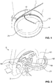
- Fig. 1
- eine perspektivische Teilansicht des Vorgangs beim Wickeln von einem Litzendraht um einen Wickeldorn bei der Herstellung einer Rundspule gemäss einem erfindungsgemässen Verfahren;
- Fig. 2
- eine perspektivische Teilansicht beim Vorgang des Umwickelns einer aus einem Litzendraht hergestellten Rundspule mit Isolationsband mittels einer Wickelmaschine gemäss einem erfindungsgemässen Verfahren;
- Fig. 3
- eine schematische Ansicht von oben her des Vorgangs beim Formen einer mit Isolationsband umwickelten Rundspule zu einer Zahnspule mittels einer kombinierten Streck- und Pressvorrichtung gemäss einem erfindungsgemässen Verfahren;
- Fig. 4
- eine Querschnittsansicht durch eine in die Nut eines Statorkerns eingesetzte Zahnspule, mit einer vergrösserten Detailansicht eines Bereiches der Zahnspule; sowie
- Fig. 5
- ein Flussdiagramm zur Illustration der Abfolge der Verfahrensschritte eines erfindungsgemässen Verfahren.
- In den
Figuren 1 bis 4 sind einzelne Schritte eines erfindungsgemässen Verfahrens zur Herstellung einer Zahnspule 3 für den Einsatz in einem Stator oder Rotor einer elektrischen Maschine gezeigt. In derFigur 5 ist die Abfolge von mehreren Verfahrensschritten bei einem beispielhaften, erfindungsgemässen Verfahren illustriert. - Als Ausgangspunkt eines beispielhaften, erfindungsgemässen Verfahrens wird ein Litzendraht 1 mit einem runden Querschnitt verwendet, welcher eine Vielzahl von üblicherweise dünnen Einzeldrähten 11 (siehe
Figur 4 ) aufweist. Die Einzeldrähte 11, bei welchen es sich insbesondere um Kupferdrähte handeln kann, können miteinander verseilt und/oder verpresst sein. - Die Drahtdurchmesser der Einzeldrähte 11 liegen typischerweise im Bereich von ca. 0.3 mm bis 2 mm. Die Einzeldrähte 11 können, müssen aber nicht, gegenseitig elektrisch voneinander isoliert sein. Die Einzeldrähte 11 können somit jeweils blank vorliegen oder eine Einzeldrahtisolation aufweisen. Die Einzeldrahtisolation kann beispielsweise als Lackschicht und/oder Oxidationsschicht ausgebildet sein. Mit einer Einzeldrahtisolation können die elektrischen Verluste beim Betrieb der elektrischen Maschine auf ein Minimum reduziert werden.
- In einem ersten Verfahrensschritt 81 (
Figur 5 ) wird der Litzendraht 1 zu einem Rechteckquerschnitt geformt. Dadurch kann in der Längsnut 71 des Statorkerns 7 (Figur 4 ) ein hoher Füllgrad erreicht werden. - In einem weiteren Verfahrensschritt 82 kann die Aussenseite des Litzendrahts 1 elektrisch isoliert werden. Es wird dabei eine Drahtisolation 13 auf den Litzendraht 1 aufgebracht, welche eine gemeinsame äussere Umhüllung aller Einzeldrähte 11 des Litzendrahtes 1 bildet. Zusammen mit den Einzeldrähten 11 bildet die Drahtisolation 13 somit den Litzendraht 1. Falls die Einzeldrähte jeweils eine Einzeldrahtisolation aufweisen, kann in bestimmten Fällen auf die Drahtisolation 13 verzichtet werden.
- Als Material für die Drahtisolation 13 kann beispielsweise eine Polyesterfolie oder eine Polyimidfolie verwendet werden. Es kann aber auch ein auf einem Folienträger aufgebrachtes Glimmerpaper verwendet werden. Die Drahtisolation 13 kann auch auf Aramidpapier, wie zum Beispiel das von der Firma Dupont vertriebene Produkt Nomex®, oder auf Glasgewebe, einer Glasumspinnung oder einem Glasgeflecht basieren.
- Die Drahtisolation 13 kann insbesondere bandförmig ausgebildet sein und spiralförmig um die Vielzahl der Einzeldrähte 11 herum gewickelt sein. Das Anbringen der bandförmigen Drahtisolation 13 kann zum Beispiel halb überlappend erfolgen. Die Drahtisolation 13 kann aber auch gestossen aufgebracht werden, was bedeutet, dass die Seitenränder der bandförmigen Drahtisolation von Spiralwindung zu Spiralwindung jeweils aneinander angrenzen ohne sich gegenseitig zu überlappen. Falls die Drahtisolation 13 gestossen aufgebracht wird, werden in der Regel zumindest zwei Lagen versetzt zueinander aufgebracht, wobei der Versatz typischerweise zum Beispiel 30 % oder 50 % der Bandbreite beträgt. Die Drahtisolation 13 kann eine beliebige Anzahl von Lagen umfassen, welche auf beliebige Art und Weise mit oder ohne gegenseitigen Versatz auf die Vielzahl der Einzelleiter 11 aufgebracht werden.
- Im Verfahrensschritt 83 wird der zu einem Recheckprofil gewalzte und mit einer Drahtisolation 13 versehene Litzendraht 1 zu einer Rundspule 2 gewickelt. Dazu wird, wie es in der
Figur 1 erkennbar ist, ein Wickeldorn 4 mit einer hier kreisrunden Aussenfläche verwendet, um welche herum der Litzendraht 1 gewickelt wird. Die Rundspule 2 erhält dadurch eine insgesamt im Wesentlichen flache Form mit einer im Wesentlichen kreisrunden Spulenöffnung 21. Die Spulenöffnung 21 ist umlaufend vom Litzendraht 1 begrenzt. - Das erste freie Drahtende 12 des Litzendrahtes 1, welches in der
Figur 1 sichtbar ist, wird beim Wickeln auf dem Wickeldorn 4 zu einer Rundspule 2 in einer entsprechend dafür vorgesehenen Haltevorrichtung des Wickeldorns gehalten, so dass der Zugang zu diesem Drahtende 12 auch nach dem Wickelvorgang gewährleistet ist. - Die Rundspule 2 wird anschliessend, im Verfahrensschritt 84 (
Figur 5 ), mittels einer Wickelmaschine 5 mit einem Isolationsband 54 umwickelt. Dieser Verfahrensschritt ist in derFigur 2 gezeigt. Das Isolationsband 54 dient dazu, die Rundspule 2 elektrisch nach aussen hin zu isolieren, so dass beim späteren Einsatz in der elektrischen Maschine keine Kurzschlussströme zum Blechpaket auftreten können. Das Isolationsband 54 bildet die Hauptisolation der Rundspule 2 bzw. der Zahnspule 3. - Die Wickelmaschine 5 weist eine Haltevorrichtung 51 auf, in welcher ein Wickelring 52 drehbar gelagert ist. Am Wickelring 52 sind zwei Bandrollen 53 diametral gegenüberliegend zueinander angebracht, welche im Wesentlichen frei drehbar sind, und auf welchen jeweils ein Isolationsband 54 aufgewickelt ist.
- Das Isolationsband 54 basiert bevorzugt auf Glimmer. Je nachdem, welches elektrische Spannungsniveau für die jeweilige Zahnspule 3 beim Einsatz in der elektrischen Maschine vorgesehen ist, kann eine entsprechende Anzahl von Lagen des Isolationsbandes 54 auf die Rundspule 2 aufgebracht werden. Alternativ oder ergänzend können eine oder mehrere Lagen des Isolationsbandes 54 auch manuell auf die Rundspule 2 aufgebracht werden. Das Isolationsband 54 kann insbesondere in den Bereichen der Drahtenden 12 von Hand aufgebracht werden.
- Während des in der
Figur 2 gezeigten Isolationsvorgangs durchragt die Rundspule 2 den Wickelring 52 der Wickelmaschine 5 ebenso wie der Wickelring 52 selbst die Spulenöffnung 21 der Rundspule 2 durchragt. Der kreisförmige Wickelring 52 umgibt den Litzendraht 1 der Rundspule 2 dabei vollständig. Für den Umwicklungsvorgang wird das in der ersten Bandrolle 53 gelagerte Isolationsband 54 an der Aussenseite des den Wickelring 1 durchragenden Litzendrahtes 1 der Rundspule 2 befestigt. Ebenso wird das Isolationsband 54, welches in der zweiten Bandrolle 53 gelagert ist, an der Aussenseite der Rundspule 2 befestigt. Für die Umwicklung wird der Wickelring 52 dann um den Litzendraht 1 der Rundspule 2 gedreht, so dass er sich mit den Bandrollen 53 durch die Spulenöffnung 21 hindurch bewegt. Gleichzeitig wird der Wickelring 52 kontinuierlich entlang des Litzendrahtes 1 bzw. in Umfangsrichtung der Rundspule 2 fortbewegt. Für den Antrieb des Wickelrings 52 ist ein an der Haltevorrichtung 51 angebrachter Antriebsmotor vorgesehen. Während sich der Wickelring 52 um den Litzendraht 1 der Rundspule 2 dreht, wird Isolationsband 54 von den beiden Bandrollen 53 abgerollt. Der Umwicklungsvorgang der Rundspule 2 mit Hilfe einer Wickelmaschine des Standes der Technik mit Wickelring 52, wie in derFigur 2 gezeigt, ist dem Fachmann hinlänglich bekannt. - Aufgrund der kreisrunden Form der Rundspule 2 weist die Spulenöffnung 21 eine maximale Grösse auf. Die Rundspule 2 ist dadurch optimal für die vollautomatische maschinelle Umwicklung mit Isolationsband 54 geeignet. Aufgrund der grossen Spulenöffnung 21 können insbesondere verhältnismässig grosse Bandrollen 53 verwendet werden, welche entsprechend weniger oft, im Idealfall während des Umwickelns einer Rundspule 2 sogar gar nie, ausgewechselt werden müssen. Die maschinelle Umwicklung ermöglicht eine regelmässige Umwicklung der Rundspule 2 mit genau vorbestimmbaren Wickelparametern wie Bandwinkel, Bandzug, Überlappung etc. Gleichzeitig kann die Umwicklung innert kurzer Zeit und mit minimalem Aufwand durchgeführt werden.
- Nach Aufbringen der Hauptisolation, also des Isolationsbandes 54, kann diese allenfalls noch mit einem Nutglimmschutzband umhüllt werden. Dies ist erforderlich bei Maschinenspannungen grösser 1kV, um sogenannte Nutentladungen zu vermeiden. Das Nutglimmschutzband, welches beim Einsatz in der elektrischen Maschine direkt zwischen der Hauptisolation und dem Eisen des Stator- bzw. Rotorkerns zu liegen kommt, kann maschinell mittels der Wickelmaschine 5 oder von Hand aufgebracht werden. Optional kann in den Bereichen der späteren Spulenstirnseiten, noch ein Endenglimmschutzband aufgebracht werden, welches ausserhalb der Längsnuten 71 des Statorkerns 7 (
Fig. 4 ) zu liegen kommt, allenfalls noch ein Schrumpfband angebracht werden. - Anschliessend wird die mit Isolationsband 54 umwickelte Rundspule 2 in einem weiteren Verfahrensschritt 85 (
Figur 5 ) in die endgültige Form der in der elektrischen Maschine verwendeten Zahnspule 3 gebracht. Die Rundspule 2 wird hierzu in eine Formvorrichtung 6 gebracht, wie sie schematisch in derFigur 3 gezeigt ist. - Die Anfangsform und -position der in die Formvorrichtung 6 gebrachten Rundspule 2 ist in der
Figur 3 mit gestrichelten Linien gezeigt. Die Rundspule 2 wird derart in die Formvorrichtung 6 eingesetzt, dass die Spulenöffnung 21 von zwei Streckdornen 61 der Formvorrichtung 6 durchragt wird. Dabei liegt die Rundspule 2 auf der Oberfläche eines Tisches 64 der Formvorrichtung 6 auf und ist zudem zwischen zwei Presselementen 62 angeordnet. Die Formvorrichtung 6 kann zwei Anschlagplatten 63 aufweisen, welche zu Beginn des Formvorgangs jedoch noch im Tisch 64 versenkt sind und insbesondere nicht in die Spulenöffnung 21 hineinragen. Die Anschlagplatten 63 erstrecken sich parallel zueinander. - Die beiden Streckdorne 61 werden dann bis zum Anschlag mit der radialen Innenseite der Rundspule 2 nach aussen verschoben. Diese Anfangsposition der Streckdorne 61 ist in der
Figur 3 gezeigt. Um die Rundspule 2 in eine längliche Form zu bringen, werden die Streckdorne 61 anschliessend in Richtung der in derFigur 3 gezeigten Pfeile weiter nach aussen und voneinander weg verschoben, so dass die Rundspule 2 entlang einer Längsrichtung gestreckt oder, anders ausgedrückt, auseinandergezogen wird. - Gleichzeitig oder anschliessend an das Auseinanderziehen der Rundspule 2 mittels der Streckdorne 61, wird die Spule mittels der beiden Presselemente 62 in eine senkrecht zur Längsrichtung stehende Richtung von den Seiten her zusammengepresst. Der Streckvorgang wird dadurch durch den Pressvorgang unterstützt bzw. ergänzt. Bei der Formvorrichtung 6 handelt es sich somit um eine kombinierte Streck- und Pressvorrichtung.
- Sobald die beiden Streckdorne 61 bis zu einem bestimmten Punkt auseinandergefahren sind und die Spulenöffnung 21 eine gewisse Längserstreckung in Längsrichtung aufweist, können die beiden Anschlagplatten 63 aus dem Tisch 64 nach oben gefahren werden, so dass sie in die Spulenöffnung 21 hineinragen. Der Streck- und Pressvorgang wird fortgesetzt bis die Längsseiten der Spule an den Anschlagplatten 63 anschlagen und durch diese in eine geradlinige Endform gebracht werden. Die Streckdorne 61 nehmen dann die in der
Figur 3 gezeigte Endposition im Bereich der Spulenstirnseiten der Zahnspule 3 ein. Die Zahnspule 3 ist somit in ihrer endgültigen Form. - Aufgrund der guten Biegbarkeit des Litzendrahtes 1 ist der Kraftaufwand während des Formvorgangs in der Formvorrichtung 6 verhältnismässig gering. Das Risiko, dass die Hauptisolation und somit das Isolationsband 54 dabei beschädigt wird, wird dadurch vermindert. Es kann dadurch, wie es im vorliegenden Ausführungsbeispiel der Fall ist, eine verhältnismässig grosse Formveränderung von der kreisrunden Rundspule 2 zur länglichen Zahnspule 3 stattfinden, ohne dass die Isolation beschädigt wird.
- Im Verfahrensschritt 86 (
Fig. 5 ) wird die Zahnspule 3 dann in eine Längsnut 71 eines Statorkerns 7 eingesetzt. Die Längsnut 71 wird dabei in Umfangsrichtung des in derFigur 4 nur teilweise gezeigten Statorkerns 7 von Zähnen 72 begrenzt. - Im letzten Verfahrensschritt 87 (
Fig. 5 ) werden die Längsnuten 71 verschlossen. Dies kann, muss aber nicht, mit jeweils einem Verschlusskeil 74 erreicht werden, der in Einsatzrillen 73 eingesetzt wird, welche an den Zähnen 72 des Statorkerns 7 vorgesehen sind. Der Statorkern 7 ist üblicherweise als Blechkörper ausgebildet und kann in voneinander trennbare Segmente aufgeteilt sein. - Nach dem Anbringen der Zahnspulen 3 am Statorkern 7 kann dieser zusammen mit den darin eingesetzten Zahnspulen 3 mittels Ganztränktechnik in einem Harzbad unter Vakuum imprägniert werden. Das entsprechende Vorgehen ist dem Fachmann bekannt.
- Alternativ können die Zahnspulen 3 auch jeweils separat voneinander und getrennt vom Statorkern 3 in einem Harzbad und unter Vakuum imprägniert werden. In diesem Fall werden die Zahnspulen 3 jeweils in einen entsprechend vorbereiteten und geformten Formkörper eingebracht, welcher im Wesentlichen der Geometrie der Längsnut 71 entspricht. Vor dem Einbringen der Zahnspule 3 wird eine Trennfolie in den Formkörper eingelegt, um die Zahnspule 3 vom Formkörper zu trennen. Der Formkörper wird dann verschlossen und die darin aufgenommene Zahnspule 3 mittels eines Vakuumimprägnierverfahrens mit einem Harz imprägniert. Nach dem Aushärten in einem Ofen wird die Zahnspule 3 aus dem Formkörper herausgenommen und die Trennfolie sowie gegebenenfalls die in den Bereichen der Spulenstirnseiten zuvor aufgebrachten Schrumpfbänder entfernt. Auch dieses Vorgehen ist dem Fachmann hinlänglich bekannt.
- Die vorliegende Erfindung ist selbstverständlich nicht auf das erläuterte Ausführungsbeispiel beschränkt, und eine Vielzahl von Abwandlungen ist möglich. So kann zum Beispiel die Wickelmaschine eine komplett andere Ausgestaltung aufweisen, als dies in der
Figur 2 dargestellt ist. Die Verwendung einer Wickelmaschine kann sogar gänzlich entfallen, und die Rundspule 2 kann von Hand mit Isolationsband 54 umwickelt werden. Die grosse, insbesondere kreisrunde Spulenöffnung 21 der Rundspule 2 erlaubt auch dann eine einfache Umwicklung. Auch die Formvorrichtung 6 kann selbstverständlich eine andere Ausgestaltung aufweisen. Eine beliebige Anzahl weiterer Verfahrensschritte können hinzukommen, und eine Vielzahl weiterer Abwandlungen ist denkbar.BEZUGSZEICHENLISTE 1 Litzendraht 54 Isolationsband 11 Einzeldraht 12 Drahtende 6 Formvorrichtung 13 Drahtisolation 61 Streckdorn 62 Presselement 2 Rundspule 63 Anschlagplatte 21 Spulenöffnung 64 Tisch 3 Zahnspule 7 Statorkern 71 Längsnut 4 Wickeldorn 72 Zahn 73 Einsatzrille 5 Wickelmaschine 74 Verschlusskeil 51 Haltevorrichtung 52 Wickelring 81-87 Verfahrensschritte 53 Bandrolle
Claims (9)
- Verfahren zur Herstellung einer Zahnspule (3) für den Einsatz in einem Stator oder Rotor einer elektrischen Maschine, aufweisend zumindest die folgenden Schritte:- Wickeln von zumindest einem Litzendraht (1) zu einer Rundspule (2);- Umwickeln dieser Rundspule (2) mit Isolationsband (54); sowie- Formen der mit dem Isolationsband (54) umwickelten Rundspule (2) in die endgültige Form einer Zahnspule (3), wobei die Rundspule (2) derart in eine kombinierte Streck- und Pressvorrichtung (6) eingesetzt wird, dass eine Spulenöffnung (21) der Rundspule (2) von zwei Streckdornen (61) der kombinierten Streck- und Pressvorrichtung (6) durchragt wird, wobei die beiden Streckdorne (61) anschliessend nach aussen und voneinander weg verschoben werden, so dass die Rundspule (2) entlang einer Längsrichtung auseinandergezogen wird, wobei die Rundspule (2) zudem mittels zumindest eines Presselements (62) in eine im Wesentlichen senkrecht zur Längsrichtung stehende Richtung zusammengepresst wird, und wobei zumindest ein Anschlagelement (63), welches eine grössere Länge aufweist als der Aussendurchmesser der Spulenöffnung (21) zu Beginn des Formvorgangs, während des Formens der Rundspule (2) zur Zahnspule (3) in die Spulenebene hinein bewegt wird, um die beim Formvorgang zu erreichende endgültige Form der Zahnspule (3) zu definieren.
- Verfahren nach Anspruch 1, wobei das Umwickeln der Rundspule (2) mit Isolationsband (54) maschinell mittels einer Wickelmaschine (5) erfolgt.
- Verfahren nach Anspruch 2, wobei das Umwickeln der Rundspule (2) mittels der Wickelmaschine (5) zumindest teilweise vollautomatisch erfolgt.
- Verfahren nach Anspruch 2 oder 3, wobei die Wickelmaschine (5) einen Wickelring (52) aufweist, welcher beim Umwickeln um den zumindest einen zu einer Rundspule (2) gewickelten Litzendraht (1) herum rotiert.
- Verfahren nach einem der vorhergehenden Ansprüche, wobei die Rundspule (2) eine im Wesentlichen kreisrunde Form aufweist.
- Verfahren nach einem der vorhergehenden Ansprüche, wobei die Zahnspule (3) zwei parallel zueinander verlaufende Längsseiten aufweist.
- Verfahren nach einem der vorhergehenden Ansprüche, wobei der Litzendraht (1) vor dem Wickeln zu einer Rundspule (2) derart geformt wird, dass er einen im Wesentlichen rechteckigen oder trapezförmigen Querschnitt aufweist.
- Verfahren nach einem der vorhergehenden Ansprüche, wobei der Litzendraht (1) vor dem Wickeln zu einer Rundspule (2) mittels einer Drahtisolation (13) isoliert wird.
- Verfahren nach einem der vorhergehenden Ansprüche, wobei der Litzendraht (1) eine Vielzahl von Einzeldrähten aufweist, welche mittels eines Oxidationsverfahrens gegeneinander isoliert werden.
Priority Applications (1)
| Application Number | Priority Date | Filing Date | Title |
|---|---|---|---|
| EP16162662.7A EP3089329B1 (de) | 2015-04-27 | 2016-03-29 | Verfahren zur herstellung einer zahnspule für eine elektrische maschine |
Applications Claiming Priority (2)
| Application Number | Priority Date | Filing Date | Title |
|---|---|---|---|
| EP15165152 | 2015-04-27 | ||
| EP16162662.7A EP3089329B1 (de) | 2015-04-27 | 2016-03-29 | Verfahren zur herstellung einer zahnspule für eine elektrische maschine |
Publications (2)
| Publication Number | Publication Date |
|---|---|
| EP3089329A1 EP3089329A1 (de) | 2016-11-02 |
| EP3089329B1 true EP3089329B1 (de) | 2020-08-12 |
Family
ID=55637297
Family Applications (1)
| Application Number | Title | Priority Date | Filing Date |
|---|---|---|---|
| EP16162662.7A Active EP3089329B1 (de) | 2015-04-27 | 2016-03-29 | Verfahren zur herstellung einer zahnspule für eine elektrische maschine |
Country Status (2)
| Country | Link |
|---|---|
| EP (1) | EP3089329B1 (de) |
| BR (1) | BR102016007869B1 (de) |
Citations (3)
| Publication number | Priority date | Publication date | Assignee | Title |
|---|---|---|---|---|
| US1455188A (en) * | 1919-06-23 | 1923-05-15 | Int Harvester Co | Method of forming flat coils |
| US4145804A (en) * | 1976-02-24 | 1979-03-27 | U.S. Philips Corporation | Non-circular orthocyclic coil |
| WO2002011268A1 (de) * | 2000-08-02 | 2002-02-07 | Von Roll Isola Winding Systems Gmbh | Wicklungen für elektrische maschinen mit leitern aus litze |
Family Cites Families (12)
| Publication number | Priority date | Publication date | Assignee | Title |
|---|---|---|---|---|
| SE370474B (de) * | 1971-12-20 | 1974-10-14 | Asea Ab | |
| DE4414527C1 (de) * | 1994-04-26 | 1995-08-31 | Orto Holding Ag | Elektronisch kommutierte Gleichstrommaschine |
| JP3314592B2 (ja) * | 1995-08-18 | 2002-08-12 | 神鋼電機株式会社 | 亀甲形コイルのテーピング装置、及び該装置を備えたコイル成形装置 |
| EP1115190A4 (de) * | 1999-07-15 | 2005-09-14 | Moric Kk | Drehende elektrische maschine |
| DE10260315A1 (de) | 2002-12-20 | 2004-07-08 | Siemens Ag | Extrudierte elastische Isolierung für Leiter von elektrischen Maschinen |
| JP2008109829A (ja) | 2006-10-27 | 2008-05-08 | Toyota Motor Corp | 回転電機の固定子構造及びその製造方法 |
| FI120523B (fi) | 2007-03-02 | 2009-11-13 | Abb Oy | Menetelmä sähkökoneen käämivyyhden valmistamiseksi ja sähkökoneen käämitys |
| DE102007025938A1 (de) | 2007-06-04 | 2008-12-18 | Siemens Ag | Hochspannungsmaschine mit verbindungsloser Wicklung |
| US20100090549A1 (en) | 2008-10-10 | 2010-04-15 | General Electric Company | Thermal management in a fault tolerant permanent magnet machine |
| DE102009006763A1 (de) | 2009-01-30 | 2010-08-05 | Siemens Aktiengesellschaft | Spule für eine dynamoelektrische Maschine |
| US20110260572A1 (en) | 2010-04-27 | 2011-10-27 | Honda Motor Co., Ltd. | Motor stator and manufacturing method of motor stator |
| US9112400B2 (en) | 2010-07-15 | 2015-08-18 | Siemens Aktiengesellschaft | Method for forming electrodynamic machine insulated coils |
-
2016
- 2016-03-29 EP EP16162662.7A patent/EP3089329B1/de active Active
- 2016-04-08 BR BR102016007869-5A patent/BR102016007869B1/pt active IP Right Grant
Patent Citations (3)
| Publication number | Priority date | Publication date | Assignee | Title |
|---|---|---|---|---|
| US1455188A (en) * | 1919-06-23 | 1923-05-15 | Int Harvester Co | Method of forming flat coils |
| US4145804A (en) * | 1976-02-24 | 1979-03-27 | U.S. Philips Corporation | Non-circular orthocyclic coil |
| WO2002011268A1 (de) * | 2000-08-02 | 2002-02-07 | Von Roll Isola Winding Systems Gmbh | Wicklungen für elektrische maschinen mit leitern aus litze |
Also Published As
| Publication number | Publication date |
|---|---|
| BR102016007869B1 (pt) | 2022-10-11 |
| EP3089329A1 (de) | 2016-11-02 |
| BR102016007869A2 (pt) | 2016-11-01 |
Similar Documents
| Publication | Publication Date | Title |
|---|---|---|
| EP3391512B1 (de) | Verfahren zum einbringen von isolierfolie und mindestens einem elektrischen leiter | |
| EP3542446B1 (de) | Wellenwicklungsspule für ein statorblechpaket einer elektrischen maschine | |
| DE102015120661A1 (de) | Verfahren zur Herstellung einer Spulenwicklung zum Einlegen in radial offene Nuten von Statoren oder Rotoren von Elektromaschinen | |
| DE112013007053T5 (de) | Eisenkern-Element, Stator vom Innenrotortyp für eine elektrische Rotationsmaschine sowie Herstellungsverfahren für einen Stator vom Innenrotortyp für eine elektrische Rotationsmaschine | |
| WO2013023820A2 (de) | Wicklungsträger zur verwendung in einer elektrischen maschine sowie wicklungsanordnung | |
| EP3542379B1 (de) | Verfahren und vorrichtung zur herstellung eines windungskörpers | |
| DE112012003454T5 (de) | Verfahren zum Herstellen eines Stators und Spuleneinführungsvorrichtung | |
| EP3534498B1 (de) | Verfahren und vorrichtung zum herstellen eines stators mit einer wicklung mit geschränkten luftspulen | |
| DE112012003437T5 (de) | Statorherstellungsverfahren und Statorherstellungsvorrichtung | |
| DE112015000717T5 (de) | Rotierende elektrische Maschine und Verfahren zum Herstellen einer Spule für eine rotierende elektrische Maschine | |
| DE102014217289A1 (de) | Wicklungsanordnung und Verfahren zur Herstellung einer Wicklungsanordnung | |
| DE102009056676A1 (de) | Wicklung für eine elektrische Maschine sowie ein Verfahren zur Herstellung einer solchen Wicklung | |
| DE102012220855A1 (de) | Stator für eine elektrische Maschine und Verfahren zur Herstellung des Stators | |
| EP3909121A1 (de) | Verfahren und vorrichtung zum mehrlagigen einfügen einer spulenmatte in ein bauteil einer elektrischen maschine | |
| EP3089329B1 (de) | Verfahren zur herstellung einer zahnspule für eine elektrische maschine | |
| DE102016221534A1 (de) | Verfahren zur Herstellung einer Anordnung von Spulen mit mindestens zwei Spulenwicklungen | |
| EP3043456A1 (de) | Verfahren zur Herstellung eines Stator- oder Rotorelements für eine elektrische Maschine | |
| DE102010043976A1 (de) | Komponente zum Herstellen einer Maschinenkomponente für eine elektrische Maschine | |
| EP3544161A1 (de) | Verfahren und vorrichtung zum einbringen einer wellenwickelmatte in den rotor oder stator einer elektrischen maschine, insbesondere in en statorblechpaket | |
| WO2015000639A2 (de) | Maschinenkomponente für eine elektrische maschine mit mehreren wicklungen | |
| DE202012104118U1 (de) | Gezogener Draht mit Isolierung | |
| WO2017042013A1 (de) | Verfahren zur herstellung einer formspule für eine elektrische maschine mittels flachdraht | |
| DE102020118925A1 (de) | Verfahren zur Herstellung einer Spulenwicklung und Wickelschablone | |
| WO2016005076A1 (de) | Verfahren zum herstellen einer elektrischen maschine mit formspulen sowie elektrische maschine und herstellungswerkzeug | |
| DE102013205240A1 (de) | Rotor oder Stator für eine elektrische Maschine und Verfahren zu seiner Herstellung |
Legal Events
| Date | Code | Title | Description |
|---|---|---|---|
| PUAI | Public reference made under article 153(3) epc to a published international application that has entered the european phase |
Free format text: ORIGINAL CODE: 0009012 |
|
| AK | Designated contracting states |
Kind code of ref document: A1 Designated state(s): AL AT BE BG CH CY CZ DE DK EE ES FI FR GB GR HR HU IE IS IT LI LT LU LV MC MK MT NL NO PL PT RO RS SE SI SK SM TR |
|
| AX | Request for extension of the european patent |
Extension state: BA ME |
|
| STAA | Information on the status of an ep patent application or granted ep patent |
Free format text: STATUS: REQUEST FOR EXAMINATION WAS MADE |
|
| 17P | Request for examination filed |
Effective date: 20170425 |
|
| RBV | Designated contracting states (corrected) |
Designated state(s): AL AT BE BG CH CY CZ DE DK EE ES FI FR GB GR HR HU IE IS IT LI LT LU LV MC MK MT NL NO PL PT RO RS SE SI SK SM TR |
|
| STAA | Information on the status of an ep patent application or granted ep patent |
Free format text: STATUS: EXAMINATION IS IN PROGRESS |
|
| 17Q | First examination report despatched |
Effective date: 20180313 |
|
| GRAP | Despatch of communication of intention to grant a patent |
Free format text: ORIGINAL CODE: EPIDOSNIGR1 |
|
| STAA | Information on the status of an ep patent application or granted ep patent |
Free format text: STATUS: GRANT OF PATENT IS INTENDED |
|
| INTG | Intention to grant announced |
Effective date: 20200320 |
|
| GRAS | Grant fee paid |
Free format text: ORIGINAL CODE: EPIDOSNIGR3 |
|
| GRAA | (expected) grant |
Free format text: ORIGINAL CODE: 0009210 |
|
| STAA | Information on the status of an ep patent application or granted ep patent |
Free format text: STATUS: THE PATENT HAS BEEN GRANTED |
|
| AK | Designated contracting states |
Kind code of ref document: B1 Designated state(s): AL AT BE BG CH CY CZ DE DK EE ES FI FR GB GR HR HU IE IS IT LI LT LU LV MC MK MT NL NO PL PT RO RS SE SI SK SM TR |
|
| REG | Reference to a national code |
Ref country code: CH Ref legal event code: EP |
|
| REG | Reference to a national code |
Ref country code: IE Ref legal event code: FG4D Free format text: LANGUAGE OF EP DOCUMENT: GERMAN |
|
| REG | Reference to a national code |
Ref country code: DE Ref legal event code: R096 Ref document number: 502016010795 Country of ref document: DE |
|
| REG | Reference to a national code |
Ref country code: AT Ref legal event code: REF Ref document number: 1302518 Country of ref document: AT Kind code of ref document: T Effective date: 20200915 |
|
| REG | Reference to a national code |
Ref country code: FI Ref legal event code: FGE |
|
| REG | Reference to a national code |
Ref country code: SE Ref legal event code: TRGR |
|
| REG | Reference to a national code |
Ref country code: LT Ref legal event code: MG4D |
|
| REG | Reference to a national code |
Ref country code: NL Ref legal event code: MP Effective date: 20200812 |
|
| PG25 | Lapsed in a contracting state [announced via postgrant information from national office to epo] |
Ref country code: GR Free format text: LAPSE BECAUSE OF FAILURE TO SUBMIT A TRANSLATION OF THE DESCRIPTION OR TO PAY THE FEE WITHIN THE PRESCRIBED TIME-LIMIT Effective date: 20201113 Ref country code: NO Free format text: LAPSE BECAUSE OF FAILURE TO SUBMIT A TRANSLATION OF THE DESCRIPTION OR TO PAY THE FEE WITHIN THE PRESCRIBED TIME-LIMIT Effective date: 20201112 Ref country code: LT Free format text: LAPSE BECAUSE OF FAILURE TO SUBMIT A TRANSLATION OF THE DESCRIPTION OR TO PAY THE FEE WITHIN THE PRESCRIBED TIME-LIMIT Effective date: 20200812 Ref country code: BG Free format text: LAPSE BECAUSE OF FAILURE TO SUBMIT A TRANSLATION OF THE DESCRIPTION OR TO PAY THE FEE WITHIN THE PRESCRIBED TIME-LIMIT Effective date: 20201112 Ref country code: HR Free format text: LAPSE BECAUSE OF FAILURE TO SUBMIT A TRANSLATION OF THE DESCRIPTION OR TO PAY THE FEE WITHIN THE PRESCRIBED TIME-LIMIT Effective date: 20200812 |
|
| PG25 | Lapsed in a contracting state [announced via postgrant information from national office to epo] |
Ref country code: LV Free format text: LAPSE BECAUSE OF FAILURE TO SUBMIT A TRANSLATION OF THE DESCRIPTION OR TO PAY THE FEE WITHIN THE PRESCRIBED TIME-LIMIT Effective date: 20200812 Ref country code: PL Free format text: LAPSE BECAUSE OF FAILURE TO SUBMIT A TRANSLATION OF THE DESCRIPTION OR TO PAY THE FEE WITHIN THE PRESCRIBED TIME-LIMIT Effective date: 20200812 Ref country code: RS Free format text: LAPSE BECAUSE OF FAILURE TO SUBMIT A TRANSLATION OF THE DESCRIPTION OR TO PAY THE FEE WITHIN THE PRESCRIBED TIME-LIMIT Effective date: 20200812 Ref country code: NL Free format text: LAPSE BECAUSE OF FAILURE TO SUBMIT A TRANSLATION OF THE DESCRIPTION OR TO PAY THE FEE WITHIN THE PRESCRIBED TIME-LIMIT Effective date: 20200812 Ref country code: IS Free format text: LAPSE BECAUSE OF FAILURE TO SUBMIT A TRANSLATION OF THE DESCRIPTION OR TO PAY THE FEE WITHIN THE PRESCRIBED TIME-LIMIT Effective date: 20201212 |
|
| PG25 | Lapsed in a contracting state [announced via postgrant information from national office to epo] |
Ref country code: DK Free format text: LAPSE BECAUSE OF FAILURE TO SUBMIT A TRANSLATION OF THE DESCRIPTION OR TO PAY THE FEE WITHIN THE PRESCRIBED TIME-LIMIT Effective date: 20200812 Ref country code: CZ Free format text: LAPSE BECAUSE OF FAILURE TO SUBMIT A TRANSLATION OF THE DESCRIPTION OR TO PAY THE FEE WITHIN THE PRESCRIBED TIME-LIMIT Effective date: 20200812 Ref country code: SM Free format text: LAPSE BECAUSE OF FAILURE TO SUBMIT A TRANSLATION OF THE DESCRIPTION OR TO PAY THE FEE WITHIN THE PRESCRIBED TIME-LIMIT Effective date: 20200812 Ref country code: RO Free format text: LAPSE BECAUSE OF FAILURE TO SUBMIT A TRANSLATION OF THE DESCRIPTION OR TO PAY THE FEE WITHIN THE PRESCRIBED TIME-LIMIT Effective date: 20200812 Ref country code: EE Free format text: LAPSE BECAUSE OF FAILURE TO SUBMIT A TRANSLATION OF THE DESCRIPTION OR TO PAY THE FEE WITHIN THE PRESCRIBED TIME-LIMIT Effective date: 20200812 |
|
| REG | Reference to a national code |
Ref country code: DE Ref legal event code: R097 Ref document number: 502016010795 Country of ref document: DE |
|
| PG25 | Lapsed in a contracting state [announced via postgrant information from national office to epo] |
Ref country code: ES Free format text: LAPSE BECAUSE OF FAILURE TO SUBMIT A TRANSLATION OF THE DESCRIPTION OR TO PAY THE FEE WITHIN THE PRESCRIBED TIME-LIMIT Effective date: 20200812 Ref country code: AL Free format text: LAPSE BECAUSE OF FAILURE TO SUBMIT A TRANSLATION OF THE DESCRIPTION OR TO PAY THE FEE WITHIN THE PRESCRIBED TIME-LIMIT Effective date: 20200812 |
|
| PLBE | No opposition filed within time limit |
Free format text: ORIGINAL CODE: 0009261 |
|
| STAA | Information on the status of an ep patent application or granted ep patent |
Free format text: STATUS: NO OPPOSITION FILED WITHIN TIME LIMIT |
|
| PG25 | Lapsed in a contracting state [announced via postgrant information from national office to epo] |
Ref country code: SK Free format text: LAPSE BECAUSE OF FAILURE TO SUBMIT A TRANSLATION OF THE DESCRIPTION OR TO PAY THE FEE WITHIN THE PRESCRIBED TIME-LIMIT Effective date: 20200812 |
|
| 26N | No opposition filed |
Effective date: 20210514 |
|
| PG25 | Lapsed in a contracting state [announced via postgrant information from national office to epo] |
Ref country code: IT Free format text: LAPSE BECAUSE OF FAILURE TO SUBMIT A TRANSLATION OF THE DESCRIPTION OR TO PAY THE FEE WITHIN THE PRESCRIBED TIME-LIMIT Effective date: 20200812 |
|
| PG25 | Lapsed in a contracting state [announced via postgrant information from national office to epo] |
Ref country code: SI Free format text: LAPSE BECAUSE OF FAILURE TO SUBMIT A TRANSLATION OF THE DESCRIPTION OR TO PAY THE FEE WITHIN THE PRESCRIBED TIME-LIMIT Effective date: 20200812 |
|
| PG25 | Lapsed in a contracting state [announced via postgrant information from national office to epo] |
Ref country code: MC Free format text: LAPSE BECAUSE OF FAILURE TO SUBMIT A TRANSLATION OF THE DESCRIPTION OR TO PAY THE FEE WITHIN THE PRESCRIBED TIME-LIMIT Effective date: 20200812 |
|
| GBPC | Gb: european patent ceased through non-payment of renewal fee |
Effective date: 20210329 |
|
| REG | Reference to a national code |
Ref country code: BE Ref legal event code: MM Effective date: 20210331 |
|
| PG25 | Lapsed in a contracting state [announced via postgrant information from national office to epo] |
Ref country code: LU Free format text: LAPSE BECAUSE OF NON-PAYMENT OF DUE FEES Effective date: 20210329 Ref country code: GB Free format text: LAPSE BECAUSE OF NON-PAYMENT OF DUE FEES Effective date: 20210329 Ref country code: IE Free format text: LAPSE BECAUSE OF NON-PAYMENT OF DUE FEES Effective date: 20210329 |
|
| REG | Reference to a national code |
Ref country code: AT Ref legal event code: MM01 Ref document number: 1302518 Country of ref document: AT Kind code of ref document: T Effective date: 20210329 |
|
| PG25 | Lapsed in a contracting state [announced via postgrant information from national office to epo] |
Ref country code: BE Free format text: LAPSE BECAUSE OF NON-PAYMENT OF DUE FEES Effective date: 20210331 |
|
| PG25 | Lapsed in a contracting state [announced via postgrant information from national office to epo] |
Ref country code: AT Free format text: LAPSE BECAUSE OF NON-PAYMENT OF DUE FEES Effective date: 20210329 |
|
| PG25 | Lapsed in a contracting state [announced via postgrant information from national office to epo] |
Ref country code: PT Free format text: LAPSE BECAUSE OF FAILURE TO SUBMIT A TRANSLATION OF THE DESCRIPTION OR TO PAY THE FEE WITHIN THE PRESCRIBED TIME-LIMIT Effective date: 20201214 |
|
| PGFP | Annual fee paid to national office [announced via postgrant information from national office to epo] |
Ref country code: FR Payment date: 20230324 Year of fee payment: 8 Ref country code: FI Payment date: 20230321 Year of fee payment: 8 |
|
| PG25 | Lapsed in a contracting state [announced via postgrant information from national office to epo] |
Ref country code: HU Free format text: LAPSE BECAUSE OF FAILURE TO SUBMIT A TRANSLATION OF THE DESCRIPTION OR TO PAY THE FEE WITHIN THE PRESCRIBED TIME-LIMIT; INVALID AB INITIO Effective date: 20160329 |
|
| PGFP | Annual fee paid to national office [announced via postgrant information from national office to epo] |
Ref country code: SE Payment date: 20230314 Year of fee payment: 8 Ref country code: DE Payment date: 20230321 Year of fee payment: 8 |
|
| PG25 | Lapsed in a contracting state [announced via postgrant information from national office to epo] |
Ref country code: CY Free format text: LAPSE BECAUSE OF FAILURE TO SUBMIT A TRANSLATION OF THE DESCRIPTION OR TO PAY THE FEE WITHIN THE PRESCRIBED TIME-LIMIT Effective date: 20200812 |
|
| PGFP | Annual fee paid to national office [announced via postgrant information from national office to epo] |
Ref country code: CH Payment date: 20230401 Year of fee payment: 8 |
|
| PG25 | Lapsed in a contracting state [announced via postgrant information from national office to epo] |
Ref country code: MK Free format text: LAPSE BECAUSE OF FAILURE TO SUBMIT A TRANSLATION OF THE DESCRIPTION OR TO PAY THE FEE WITHIN THE PRESCRIBED TIME-LIMIT Effective date: 20200812 |
|
| PGFP | Annual fee paid to national office [announced via postgrant information from national office to epo] |
Ref country code: FI Payment date: 20240320 Year of fee payment: 9 Ref country code: DE Payment date: 20240320 Year of fee payment: 9 |