EP3089321A1 - Power-transmitting device, power-feeding system, and device for adjusting impedance of electrical circuit - Google Patents
Power-transmitting device, power-feeding system, and device for adjusting impedance of electrical circuit Download PDFInfo
- Publication number
- EP3089321A1 EP3089321A1 EP13899146.8A EP13899146A EP3089321A1 EP 3089321 A1 EP3089321 A1 EP 3089321A1 EP 13899146 A EP13899146 A EP 13899146A EP 3089321 A1 EP3089321 A1 EP 3089321A1
- Authority
- EP
- European Patent Office
- Prior art keywords
- coil
- power
- power transmission
- turning
- state
- Prior art date
- Legal status (The legal status is an assumption and is not a legal conclusion. Google has not performed a legal analysis and makes no representation as to the accuracy of the status listed.)
- Withdrawn
Links
Images





Classifications
-
- H—ELECTRICITY
- H02—GENERATION; CONVERSION OR DISTRIBUTION OF ELECTRIC POWER
- H02J—ELECTRIC POWER NETWORKS; CIRCUIT ARRANGEMENTS OR SYSTEMS FOR SUPPLYING OR DISTRIBUTING ELECTRIC POWER; SYSTEMS FOR STORING ELECTRIC ENERGY
- H02J50/00—Circuit arrangements or systems for wireless supply or distribution of electric power
- H02J50/10—Circuit arrangements or systems for wireless supply or distribution of electric power using inductive coupling
- H02J50/12—Circuit arrangements or systems for wireless supply or distribution of electric power using inductive coupling of the resonant type
-
- H—ELECTRICITY
- H01—ELECTRIC ELEMENTS
- H01F—MAGNETS; INDUCTANCES; TRANSFORMERS; SELECTION OF MATERIALS FOR THEIR MAGNETIC PROPERTIES
- H01F38/00—Adaptations of transformers or inductances for specific applications or functions
- H01F38/14—Inductive couplings
-
- H—ELECTRICITY
- H02—GENERATION; CONVERSION OR DISTRIBUTION OF ELECTRIC POWER
- H02J—ELECTRIC POWER NETWORKS; CIRCUIT ARRANGEMENTS OR SYSTEMS FOR SUPPLYING OR DISTRIBUTING ELECTRIC POWER; SYSTEMS FOR STORING ELECTRIC ENERGY
- H02J50/00—Circuit arrangements or systems for wireless supply or distribution of electric power
- H02J50/10—Circuit arrangements or systems for wireless supply or distribution of electric power using inductive coupling
-
- H—ELECTRICITY
- H02—GENERATION; CONVERSION OR DISTRIBUTION OF ELECTRIC POWER
- H02J—ELECTRIC POWER NETWORKS; CIRCUIT ARRANGEMENTS OR SYSTEMS FOR SUPPLYING OR DISTRIBUTING ELECTRIC POWER; SYSTEMS FOR STORING ELECTRIC ENERGY
- H02J50/00—Circuit arrangements or systems for wireless supply or distribution of electric power
- H02J50/90—Circuit arrangements or systems for wireless supply or distribution of electric power involving detection or optimisation of position, e.g. alignment
-
- H—ELECTRICITY
- H01—ELECTRIC ELEMENTS
- H01F—MAGNETS; INDUCTANCES; TRANSFORMERS; SELECTION OF MATERIALS FOR THEIR MAGNETIC PROPERTIES
- H01F29/00—Variable transformers or inductances not covered by group H01F21/00
- H01F29/08—Variable transformers or inductances not covered by group H01F21/00 with core, coil, winding, or shield movable to offset variation of voltage or phase shift, e.g. induction regulators
- H01F29/12—Variable transformers or inductances not covered by group H01F21/00 with core, coil, winding, or shield movable to offset variation of voltage or phase shift, e.g. induction regulators having movable coil, winding, or part thereof; having movable shield
Definitions
- the present invention relates to a power transmission device, a power feeding system, and an impedance adjusting device of an electric circuit.
- a power feeding system that includes, for example, a power transmission device and a power receiving device (for example, PTL 1).
- the power feeding system in Patent Literature 1 controls neither transmission nor cutoff of electric power from the power transmission device to the power receiving device. Accordingly, an increase in transmitted electric energy results in an increase in a current supplied to a power transmission circuit in the power transmission device, possibly causing damage to the power transmission circuit.
- the present invention to solve the above-described problems is a power transmission device that includes a power transmission circuit, a third coil, and a turning device.
- the power transmission circuit includes a second coil.
- the second coil is configured to supply a first coil of a power receiving device with electric power.
- the third coil is magnetically coupled with the second coil.
- the turning device causes the third coil to turn about a turning shaft to change an impedance of the power transmission circuit such that the electric power is cut off or supplied.
- the turning shaft intersects with a winding shaft of the second coil.
- electric power supplied from a power transmission device to a power receiving device can be cut off or transmitted.
- Fig. 1 is a perspective view illustrating the power feeding system of the present embodiment. Although an inside of casings 25 and 35 cannot be seen, for convenience of explanation, the inside is indicated by dashed lines.
- Fig. 2 is a cross-sectional view illustrating the power feeding system of the present embodiment. Fig. 2 illustrates a cross section of a power feeding system 100 cut parallel to an X-Z plane along an approximately center of the power feeding system 100 in Fig. 1 and viewed toward +Y.
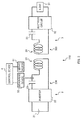
- Fig. 3 is a drawing illustrating the power feeding system of the present embodiment.
- the power feeding system 100 is a system that performs wireless power transmission using, for example, a resonance phenomenon in an electromagnetic field.
- a Z-axis is an axis along winding shafts 241 and 341 and also along a vertical direction.
- a direction from the power transmission device 2 to the power receiving device 3 is defined as +Z while a direction from the power receiving device 3 to the power transmission device 2 is defined as -Z.
- An X-axis is an axis along a turning shaft 262.
- a direction from one end of the turning shaft 262 journaled to a bearing 27 to the other end of the turning shaft 262 journaled to a bearing 28 is defined as +X while a direction from the other end of the turning shaft 262 to the one end is defined as -X.
- AY axis is an axis orthogonal to the X-axis and the Z-axis.
- a direction from the front surface of the paper to the back surface of the paper is defined as +Y while a direction from the back surface of the paper to the front surface of the paper is defined as -Y.
- the power feeding system 100 includes a power transmission device 2 and a power receiving device 3.
- the power transmission device 2 is a device that wirelessly transmits electric power to the power receiving device 3.
- the power receiving device 3 is a device that receives electric power output from the power transmission device 2 and supplies electric power according to the received electric power to a load 31.
- the load 31 is an electric power load such as an electrical device that operates based on the electric power supplied from the power receiving device 3.
- the power transmission device 2 includes a power transmission coil 24, the casing 25, a turning coil 26, the bearings 27 and 28, and the turning shaft 262.
- the casing 25 houses a power transmission circuit 200 (an electric circuit), which includes the power transmission coil 24, the turning coil 26, and the turning shaft 262.
- the outer shape of the casing 25 has, for example, a columnar shape and is formed with, for example, an insulated material such as resin.
- the power transmission coil 24 is tubularly wound around the winding shaft 241, which is along the vertical direction (the Z-axis).
- the turning coil 26 is disposed at the inside of the power transmission coil 24.
- the power transmission coil 24 may be housed in an insulated case along the outer shape of the power transmission coil 24.
- the turning coil 26 is a magnetic material magnetically coupled to the power transmission coil 24.
- a turning of the turning coil 26 changes an impedance of the power transmission circuit 200.
- the turning coil 26 is wound around a winding shaft 261, which is approximately orthogonal to the turning shaft 262.
- An outer diameter of the turning coil 26 is configured to be smaller than an inner diameter of the power transmission coil 24 so as to be disposed inside the power transmission coil 24.
- the turning coil 26 is secured to the turning shaft 261.
- the turning shaft 261 continuously passing through, for example, the casing 25, the power transmission coil 24, and the turning coil 26 is journaled to the bearings 27 and 28 by both ends. Further, the turning shaft 262 is also approximately orthogonal to the winding shaft 241. Based on a rotary power transmitted from a servo motor 51, which is controlled by a control device 4, the turning shaft 261 turns clockwise (a direction A2 in Fig. 4 ) or anticlockwise (a direction A1 in Fig. 4 ) viewed from -X to +X. That is, the control device 4 turns the turning coil 26 in the A1 direction or the A2 direction around the turning shaft 262.
- the power transmission device 2 further includes a power supply 21, an inverter 22, a capacitor 23, the control device 4, the servo motor 51, and a measuring device 52.
- the turning coil 26, the control device 4, and the servo motor 51 correspond to an impedance adjusting device of the electric circuit.
- the power supply 21 generates a DC power.
- the inverter 22 converts a DC power supplied from the power supply 21 into an AC power.
- the power transmission coil 24 is a primary side coil of the power feeding system 100 to wirelessly supply a power receiving coil 34 with electric power.
- the capacitor 23 is used to set the impedance of the power transmission circuit 200.
- One end of the power supply 21 is coupled to one end of the capacitor 23 via the inverter 22.
- the other end of the power supply 21 is coupled to one end of the power transmission coil 24 via the inverter 22.
- the other end of the power transmission coil 24 is coupled to the other end of the capacitor 23.
- the DC power output from the power supply 21 is converted from DC into AC by the inverter 22 and is supplied to the power transmission coil 24.
- the AC power supplied to the power transmission coil 24 is supplied from the power transmission coil 24 to the power receiving coil 34.
- the measuring device 52 measures the current supplied to the power transmission coil 24 and transmits a cutoff signal to the control device 4. For example, when a current with a value larger than a predetermined value is measured, the measuring device 52 transmits the cutoff signal.
- the predetermined value is, for example, a value to the extent of not damaging the power transmission device 2. The predetermined value may be determined based on a specification or a similar condition of the power transmission device 2.
- the servo motor 51 provides a rotary power to turning the turning shaft 262 to the turning shaft 262.
- the control device 4 controls the servo motor 51.
- the control device 4 turns the turning coil 26 to supply and cut off the electric power from the power transmission coil 24 to the power receiving coil 34, thus changing the impedance of the power transmission circuit 200.
- the control device 4 will be described later.
- the power receiving device 3 includes the power receiving coil 34 and the casing 35.
- the casing 35 houses a power receiving circuit 300, which includes the power receiving coil 34.
- the outer shape of the casing 35 has, for example, a columnar shape and is formed with, for example, an insulated material such as resin.
- the power receiving coil 34 is wound around the winding shaft 341, which is along the vertical direction (the Z-axis).
- the power receiving coil 34 is secured to a predetermined position close to the lower side (-Z) inside the casing 35.
- the power receiving device 3 further includes a rectifier circuit 32 and a capacitor 33.
- the power receiving coil 34 is a secondary side coil of the power feeding system 100 to which electric power is wirelessly supplied from the power transmission coil 24.
- the rectifier circuit 32 converts an AC power supplied from the power receiving coil 34 into a DC power and supplies this converted DC power to the load 31.
- the capacitor 33 is used to set a value of an impedance of the power receiving circuit 300.
- One end of the power receiving coil 34 is coupled to the load 31 via the capacitor 33 and the rectifier circuit 32.
- the other end of the power receiving coil 34 is coupled to the load 31 via the rectifier circuit 32.
- These couplings form the power receiving circuit 300 including the power receiving coil 34, the capacitor 33, the rectifier circuit 32, and the load 31.
- Fig. 4 is a cross-sectional view illustrating the power feeding system of the present embodiment to which electric power is being transmitted.
- Fig. 5 is a cross-sectional view illustrating the power feeding system of the present embodiment to which transmission of electric power is being cut off.
- Fig. 4 and Fig. 5 illustrate a cross section of the power feeding system 100from cut parallel to a Y-Z plane along an approximately center of the power feeding system 100 in Fig. 1 and viewed toward -X.
- Fig. 6 is a drawing illustrating a relationship between a frequency and transmitted electric power of the present embodiment. The frequency in Fig.
- the transmitted electric power indicates the electric power transmitted from the power transmission coil 24 to the power receiving coil 34.
- This transmitted electric power is, for example, determined based on transmission efficiency of the electric power from the power transmission coil 24 to the power receiving coil 34 and a similar specification.
- the power receiving device 3 When the power transmission device 2 transmits electric power to the power receiving device 3, the power receiving device 3 is disposed at the first position. As illustrated in Fig. 4 , the first position is a position where an opposed surface 351 of the power receiving device 3 and an opposed surface 251 of the power transmission device 2 are in contact.
- the power receiving device 3 When the power transmission device 2 does not transmit electric power to the power receiving device 3, the power receiving device 3 is disposed at a second position. As illustrated in Fig. 2 , the second position is a position where the power receiving device 3 is away from the power transmission device 2 by a predetermined distance or more.
- the predetermined distance is configured based on a specification of the power feeding system 100 and a similar condition.
- the power transmission device 2 and the power receiving device 3 are set based on the transmission efficiency.
- Setting of the power transmission device 2 and the power receiving device 3 include, for example, setting the frequency of the electric power transmitted from the power transmission device 2 and impedances of the power transmission circuit 200 and the power receiving circuit 300.
- the transmission efficiency is determined based on a resonant frequency or a similar condition.
- These resonant frequencies f1 and f2 are, for example, determined based on Expression (1) to Expression (3).
- L indicates values of inductances of the power transmission circuit 200 and the power receiving circuit 300
- C indicates capacitance values of the power transmission circuit 200 and the power receiving circuit 300
- k indicates a coupling coefficient between the power transmission coil 24 and the power receiving coil 34.
- the value of the coupling coefficient k changes according to a transmission distance D ( Fig. 2 ), which indicates a distance between the power transmission coil 24 and the power receiving coil 34.
- a unique resonant frequency f 0 varies according to the value of the inductance of the power transmission circuit 200. That is, the resonant frequencies f 1 and f 2 , namely, the transmission efficiency varies according to the transmission distance D and the value of the inductance of the power transmission circuit 200. Accordingly, varying the transmission distance D and the inductance of the power transmission circuit 200 ensures transmitting or cutting off electric power from the power transmission device 2 to the power receiving device 3.
- the power transmission device 2 and the power receiving device 3 are set, for example, in a state where the power receiving device 3 is disposed at the first position.
- the power transmission device 2 and the power receiving device 3 are configured such that electric power is transmitted when a relative positional relationship between the power transmission coil 24 and the turning coil 26 is in a first positional relationship and electric power is not transmitted when the relative positional relationship between the power transmission coil 24 and the turning coil 26 is in a second positional relationship.
- the first positional relationship means the relative positional relationship between the power transmission coil 24 and the turning coil 26 when the winding shaft 241 and the winding shaft 261 are approximately orthogonal to one another.
- the second positional relationship means the relative positional relationship between the power transmission coil 24 and the turning coil 26 when the winding shaft 241 and the winding shaft 261 are approximately parallel to one another.
- diameters and the numbers of windings of the power transmission coil 24 and the turning coil 26 and a similar specification are set such that the impedance of the power transmission circuit 200 is changed to the extent that electric power is transmitted or cut off when the relative positional relationship between the power transmission coil 24 and the turning coil 26 is in the first and the second positional relationships.
- the diameters and the numbers of windings of the power transmission coil 24 and the turning coil 26 may be configured such that the value of the inductance of the power transmission circuit 200 when the power transmission coil 24 and the turning coil 26 are in the second positional relationship becomes twice or more of the value of the inductance of the power transmission circuit 200 when the power transmission coil 24 and the turning coil 26 are in the first positional relationship.
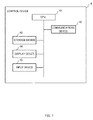
- Fig. 7 is a drawing illustrating hardware of the control device of the present embodiment.
- Fig. 8 is a drawing illustrating functions of the control device of the present embodiment.
- the control device 4 includes a Central Processing Unit (CPU) 41, a communications device 42, a storage device 43, a display device 44, and an input device 45.
- the CPU 41 executes a program stored in the storage device 43 to achieve various functions of the control device 4 and to integrally control the control device 4.
- the storage device 43 stores the above-described programs and various pieces of information.
- the display device 44 is a display to display information on the control device 4.
- the input device 45 is, for example, a keyboard and a computer mouse to input information to the control device 4.
- the communications device 42 performs communications between the servo motor 51 and the measuring device 52.
- the control device 4 further includes a detecting unit 46 and a control unit 47 (also referred to as "various functions of the control device 4").
- the execution of the program stored in the storage device 43 by the CPU 41 achieves the various functions of the control device 4.
- the detecting unit 46 When the detecting unit 46 receives the cutoff signal, the detecting unit 46 detects an abnormality in the power transmission device 2.
- the measuring device 52 may transmit the cutoff signal to the control device 4.
- a user of the power feeding system 100 may transmit the cutoff signal to the control device 4 via the input device 45.
- the control unit 47 Based on a detection result by the detecting unit 46, the control unit 47 turns the turning coil 26 in the A1 direction or the A2 direction such that the relative positional relationship between the power transmission coil 24 and the turning coil 26 is in the first positional relationship or the second positional relationship. For example, if the detecting unit 46 detects an abnormality, the control unit 47 performs a control to cut off the electric power. Alternatively, for example, when the detecting unit 46 does not detect an abnormality, the control unit 47 performs a control to transmit electric power.
- the power receiving device 3 When the power transmission device 2 does not transmit electric power to the power receiving device 3, the power receiving device 3 is disposed at the second position. This deteriorates the transmission efficiency and enters the power receiving device 3 in a state where the electric power is not transmitted.
- the power receiving device 3 When the power transmission device 2 transmits electric power to the power receiving device 3, the power receiving device 3 is disposed at the first position. Further, in this case, the control device 4 causes the turning coil 26 to turn such that the relative positional relationship between the power transmission coil 24 and the turning coil 26 is in the first positional relationship. In this case, the impedance of the power transmission circuit 200 changes and, for example, the resonant frequency approximately matches the frequency of the electric power to be transmitted. Therefore, the electric power is transmitted with improved transmission efficiency.
- the control device 4 causes the turning coil 26 to turn such that the relative positional relationship between the power transmission coil 24 and the turning coil 26 is in the first positional relationship.
- the impedance of the power transmission circuit 200 changes and, for example, the resonant frequency is shifted from the frequency of the electric power to be transmitted.
- This shift of the resonant frequency sets, for example, the transmission efficiency approximately 0. Therefore, the transmission efficiency is deteriorated, and the transmission of the electric power is cut off.
- An amount of the above-described shifting of the resonant frequency is determined by the above-described settings of the power transmission device 2 and the power receiving device 3.
- the power transmission device 2 includes the power transmission circuit 200, the turning coil 26 (a third coil), the servo motor 51, and the control device 4.
- the power transmission circuit 200 includes the power transmission coil 24 (a second coil) to transmit electric power to the power receiving coil 34 (a first coil) of the power receiving device 3.
- the turning coil 26 is magnetically coupled with the power transmission coil 24.
- the control device 4 and the servo motor 51 (a turning device) turns the turning coil 26 around the turning shaft 262, which intersects with the winding shaft 241 of the power transmission coil 24, to change the impedance of the power transmission circuit 200 such that the electric power is cut off or supplied from the power transmission coil 24 to the power receiving coil 34.
- the electric power supplied from the power transmission device 2 to the power receiving device 3 can be cut off or transmitted.
- This ensures preventing the power transmission device 2 from being damaged by supplying a current exceeding a rated current (also referred to as "an overcurrent") to the power transmission circuit 200.
- a rated current also referred to as "an overcurrent”
- this ensures improving safety of the power feeding system 100.
- this eliminates the need for disposing a breaker or a similar unit at the power transmission circuit 200. Therefore, this ensures preventing the following situation.
- a current exceeding the rated current of the breaker is supplied to the power transmission circuit 200, resulting in a breakdown of this breaker causing a failure in cutting off the overcurrent, and therefore the overcurrent would be supplied to the power transmission circuit 200.
- the turning coil 26 has a shape whose outer diameter is smaller than an inner diameter of the power transmission coil 24.
- the turning coil 26 is disposed inside the power transmission coil 24. This ensures providing a compact power transmission device 2.
- the servo motor 51 and the control device 4 turns the turning coil 26 about the turning shaft 262, which passes through the turning coil 26. Therefore, the turning of the turning coil 26 can ensure a decreased area in which the turning coil 26 moves. Accordingly, the power transmission device 2 can be configured to be further compact.
- the servo motor 51 and the control device 4 turns the turning coil 26 so as to switch the state from one state to the other state between a first state and a second state.
- the winding shaft 241 and the winding shaft 261 are approximately parallel.
- the winding shaft 241 and the winding shaft 261 are approximately orthogonal. Accordingly, expanding the variation width of the impedance of the power transmission circuit 200 by the turning of the turning coil 26 ensures to reliably transmit or cut off the electric power supplied from the power transmission device 2 to the power receiving device 3.
- the turning coil 26 is disposed inside the power transmission coil 24. However, this should not be construed in a limiting sense.
- the turning coil 26 may be disposed outside the power transmission coil 24.
- winding shaft 261 is orthogonal to the turning shaft 262.
- the winding shaft 261 intersects with the turning shaft 262 such that an angle formed by the winding shaft 261 and the turning shaft 262 is, for example, approximately 80 degrees or approximately 70 degrees.
- the above embodiment describes the turning of the turning coil 26.
- the power transmission coil 24 may be turned about the turning shaft 262. Both the power transmission coil 24 and the turning coil 26 may be turned.
- the turning shaft 262 passes through the turning coil 26.
- the turning shaft 262 may be away from the turning coil 26; therefore, the turning shaft 262 may not pass through the turning coil 26.
- the turning coil 26 is turned by approximately 90 degrees. However, this should not be construed in a limiting sense. For example, to transmit or cut off electric power, the turning coil 26 may be turned by predetermined angles other than approximately 90 degrees.
- the turning coil 24 is disposed at the power transmission device 2.
- the turning coil with a configuration similar to the turning coil 24 may be disposed inside the power receiving coil 34 of the power receiving device 3 so that the turning of this turning coil may change the impedance of the power receiving circuit 300.
- the power transmission device 2 and the power receiving device 3 are configured such that electric power is transmitted when the relative positional relationship between the power transmission coil 24 and the turning coil 26 is in the first positional relationship and electric power is not transmitted when the relative positional relationship between the power transmission coil 24 and the turning coil 26 is in the second positional relationship.
- the power transmission device 2 and the power receiving device 3 may be configured such that electric power is transmitted when the relative positional relationship between the power transmission coil 24 and the turning coil 26 is in the second positional relationship and electric power is not transmitted when the relative positional relationship between the power transmission coil 24 and the turning coil 26 is in the first positional relationship.
- the control device 4 causes the turning coil 26 to turn such that the relative positional relationship between the power transmission coil 24 and the turning coil 26 is in the second positional relationship.
- the control device 4 causes the turning coil 26 to turn such that the relative positional relationship between the power transmission coil 24 and the turning coil 26 is in the first positional relationship.
Landscapes
- Engineering & Computer Science (AREA)
- Power Engineering (AREA)
- Computer Networks & Wireless Communication (AREA)
- Charge And Discharge Circuits For Batteries Or The Like (AREA)
Abstract
Description
- The present invention relates to a power transmission device, a power feeding system, and an impedance adjusting device of an electric circuit.
- There is known a power feeding system that includes, for example, a power transmission device and a power receiving device (for example, PTL 1).
- [PTL 1] Japanese Patent Application Laid-open Publication No.
2013-70590 - For example, the power feeding system in
Patent Literature 1 controls neither transmission nor cutoff of electric power from the power transmission device to the power receiving device. Accordingly, an increase in transmitted electric energy results in an increase in a current supplied to a power transmission circuit in the power transmission device, possibly causing damage to the power transmission circuit. - The present invention to solve the above-described problems is a power transmission device that includes a power transmission circuit, a third coil, and a turning device. The power transmission circuit includes a second coil. The second coil is configured to supply a first coil of a power receiving device with electric power. The third coil is magnetically coupled with the second coil. The turning device causes the third coil to turn about a turning shaft to change an impedance of the power transmission circuit such that the electric power is cut off or supplied. The turning shaft intersects with a winding shaft of the second coil.
- Other features of the present invention will become apparent from descriptions of the accompanying drawings and of the present specification.
- According to the present invention, electric power supplied from a power transmission device to a power receiving device can be cut off or transmitted.
-
- [
Fig. 1 ]
Fig. 1 is a perspective view illustrating a power feeding system of an embodiment of the present invention. - [
Fig. 2 ]
Fig. 2 is a cross-sectional view illustrating the power feeding system of the embodiment of the present invention. - [
Fig. 3 ]
Fig. 3 is a drawing illustrating the power feeding system of the embodiment of the present invention. - [
Fig. 4 ]
Fig. 4 is a cross-sectional view illustrating the power feeding system of the embodiment of the present invention having electric power transmitted. - [
Fig. 5 ]
Fig. 5 is a cross-sectional view illustrating the power feeding system of the embodiment of the present invention having transmission of electric power cut off. - [
Fig. 6 ]
Fig. 6 is a drawing illustrating a relationship between a frequency and transmitted electric power of the embodiment of the present invention. - [
Fig. 7 ]
Fig. 7 is a drawing illustrating hardware of a control device of the embodiment of the present invention. - [
Fig. 8 ]
Fig. 8 is a drawing illustrating functions of the control device of the embodiment of the present invention. - At least the following matters will become apparent from descriptions of the present specification and of the accompanying drawings.
- The following describes the power feeding system of embodiments with reference to
Fig. 1 to Fig. 3 .Fig. 1 is a perspective view illustrating the power feeding system of the present embodiment. Although an inside ofcasings Fig. 2 is a cross-sectional view illustrating the power feeding system of the present embodiment.Fig. 2 illustrates a cross section of apower feeding system 100 cut parallel to an X-Z plane along an approximately center of thepower feeding system 100 inFig. 1 and viewed toward +Y.Fig. 3 is a drawing illustrating the power feeding system of the present embodiment. - The
power feeding system 100 is a system that performs wireless power transmission using, for example, a resonance phenomenon in an electromagnetic field. A Z-axis is an axis along windingshafts power transmission device 2 to thepower receiving device 3 is defined as +Z while a direction from thepower receiving device 3 to thepower transmission device 2 is defined as -Z. An X-axis is an axis along a turningshaft 262. A direction from one end of the turningshaft 262 journaled to abearing 27 to the other end of the turningshaft 262 journaled to abearing 28 is defined as +X while a direction from the other end of the turningshaft 262 to the one end is defined as -X. AY axis is an axis orthogonal to the X-axis and the Z-axis. A direction from the front surface of the paper to the back surface of the paper is defined as +Y while a direction from the back surface of the paper to the front surface of the paper is defined as -Y. - The
power feeding system 100 includes apower transmission device 2 and apower receiving device 3. - The
power transmission device 2 is a device that wirelessly transmits electric power to thepower receiving device 3. - The
power receiving device 3 is a device that receives electric power output from thepower transmission device 2 and supplies electric power according to the received electric power to aload 31. - The
load 31 is an electric power load such as an electrical device that operates based on the electric power supplied from thepower receiving device 3. - The
power transmission device 2 includes apower transmission coil 24, thecasing 25, aturning coil 26, thebearings shaft 262. - The
casing 25 houses a power transmission circuit 200 (an electric circuit), which includes thepower transmission coil 24, theturning coil 26, and the turningshaft 262. The outer shape of thecasing 25 has, for example, a columnar shape and is formed with, for example, an insulated material such as resin. - The
power transmission coil 24 is tubularly wound around thewinding shaft 241, which is along the vertical direction (the Z-axis). Theturning coil 26 is disposed at the inside of thepower transmission coil 24. For example, thepower transmission coil 24 may be housed in an insulated case along the outer shape of thepower transmission coil 24. - The turning
coil 26 is a magnetic material magnetically coupled to thepower transmission coil 24. A turning of theturning coil 26 changes an impedance of thepower transmission circuit 200. The turningcoil 26 is wound around a windingshaft 261, which is approximately orthogonal to the turningshaft 262. An outer diameter of the turningcoil 26 is configured to be smaller than an inner diameter of thepower transmission coil 24 so as to be disposed inside thepower transmission coil 24. The turningcoil 26 is secured to the turningshaft 261. - The turning
shaft 261 continuously passing through, for example, thecasing 25, thepower transmission coil 24, and the turningcoil 26 is journaled to thebearings shaft 262 is also approximately orthogonal to the windingshaft 241. Based on a rotary power transmitted from aservo motor 51, which is controlled by acontrol device 4, the turningshaft 261 turns clockwise (a direction A2 inFig. 4 ) or anticlockwise (a direction A1 inFig. 4 ) viewed from -X to +X. That is, thecontrol device 4 turns the turningcoil 26 in the A1 direction or the A2 direction around the turningshaft 262. - The
power transmission device 2 further includes apower supply 21, aninverter 22, acapacitor 23, thecontrol device 4, theservo motor 51, and a measuringdevice 52. The turningcoil 26, thecontrol device 4, and theservo motor 51 correspond to an impedance adjusting device of the electric circuit. - The
power supply 21 generates a DC power. Theinverter 22 converts a DC power supplied from thepower supply 21 into an AC power. Thepower transmission coil 24 is a primary side coil of thepower feeding system 100 to wirelessly supply apower receiving coil 34 with electric power. Thecapacitor 23 is used to set the impedance of thepower transmission circuit 200. - One end of the
power supply 21 is coupled to one end of thecapacitor 23 via theinverter 22. The other end of thepower supply 21 is coupled to one end of thepower transmission coil 24 via theinverter 22. The other end of thepower transmission coil 24 is coupled to the other end of thecapacitor 23. These couplings form thepower transmission circuit 200 including thepower supply 21, theinverter 22, thecapacitor 23, and thepower transmission coil 24. - The DC power output from the
power supply 21 is converted from DC into AC by theinverter 22 and is supplied to thepower transmission coil 24. The AC power supplied to thepower transmission coil 24 is supplied from thepower transmission coil 24 to thepower receiving coil 34. - The measuring
device 52 measures the current supplied to thepower transmission coil 24 and transmits a cutoff signal to thecontrol device 4. For example, when a current with a value larger than a predetermined value is measured, the measuringdevice 52 transmits the cutoff signal. The predetermined value is, for example, a value to the extent of not damaging thepower transmission device 2. The predetermined value may be determined based on a specification or a similar condition of thepower transmission device 2. - The
servo motor 51 provides a rotary power to turning the turningshaft 262 to the turningshaft 262. - The
control device 4 controls theservo motor 51. - The
control device 4 turns the turningcoil 26 to supply and cut off the electric power from thepower transmission coil 24 to thepower receiving coil 34, thus changing the impedance of thepower transmission circuit 200. Thecontrol device 4 will be described later. - The
power receiving device 3 includes thepower receiving coil 34 and thecasing 35. - The casing 35 houses a
power receiving circuit 300, which includes thepower receiving coil 34. The outer shape of thecasing 35 has, for example, a columnar shape and is formed with, for example, an insulated material such as resin. - The
power receiving coil 34 is wound around the windingshaft 341, which is along the vertical direction (the Z-axis). Thepower receiving coil 34 is secured to a predetermined position close to the lower side (-Z) inside thecasing 35. - The
power receiving device 3 further includes arectifier circuit 32 and acapacitor 33. - The
power receiving coil 34 is a secondary side coil of thepower feeding system 100 to which electric power is wirelessly supplied from thepower transmission coil 24. Therectifier circuit 32 converts an AC power supplied from thepower receiving coil 34 into a DC power and supplies this converted DC power to theload 31. Thecapacitor 33 is used to set a value of an impedance of thepower receiving circuit 300. - One end of the
power receiving coil 34 is coupled to theload 31 via thecapacitor 33 and therectifier circuit 32. The other end of thepower receiving coil 34 is coupled to theload 31 via therectifier circuit 32. These couplings form thepower receiving circuit 300 including thepower receiving coil 34, thecapacitor 33, therectifier circuit 32, and theload 31. - The following describes the settings of the power transmission device and the power receiving device according to the present embodiment with reference to
Fig. 2 andFig. 4 toFig. 6 .Fig. 4 is a cross-sectional view illustrating the power feeding system of the present embodiment to which electric power is being transmitted.Fig. 5 is a cross-sectional view illustrating the power feeding system of the present embodiment to which transmission of electric power is being cut off.Fig. 4 andFig. 5 illustrate a cross section of the power feeding system 100from cut parallel to a Y-Z plane along an approximately center of thepower feeding system 100 inFig. 1 and viewed toward -X.Fig. 6 is a drawing illustrating a relationship between a frequency and transmitted electric power of the present embodiment. The frequency inFig. 6 indicates the frequency of the electric power output from thepower transmission coil 24. The transmitted electric power indicates the electric power transmitted from thepower transmission coil 24 to thepower receiving coil 34. This transmitted electric power is, for example, determined based on transmission efficiency of the electric power from thepower transmission coil 24 to thepower receiving coil 34 and a similar specification. - When the
power transmission device 2 transmits electric power to thepower receiving device 3, thepower receiving device 3 is disposed at the first position. As illustrated inFig. 4 , the first position is a position where anopposed surface 351 of thepower receiving device 3 and anopposed surface 251 of thepower transmission device 2 are in contact. - When the
power transmission device 2 does not transmit electric power to thepower receiving device 3, thepower receiving device 3 is disposed at a second position. As illustrated inFig. 2 , the second position is a position where thepower receiving device 3 is away from thepower transmission device 2 by a predetermined distance or more. The predetermined distance is configured based on a specification of thepower feeding system 100 and a similar condition. - The
power transmission device 2 and thepower receiving device 3 are set based on the transmission efficiency. Setting of thepower transmission device 2 and thepower receiving device 3 include, for example, setting the frequency of the electric power transmitted from thepower transmission device 2 and impedances of thepower transmission circuit 200 and thepower receiving circuit 300. - As described above, the transmission efficiency is determined based on a resonant frequency or a similar condition. These resonant frequencies f1 and f2 are, for example, determined based on Expression (1) to Expression (3).
-


- L indicates values of inductances of the
power transmission circuit 200 and thepower receiving circuit 300, and C indicates capacitance values of thepower transmission circuit 200 and thepower receiving circuit 300. k indicates a coupling coefficient between thepower transmission coil 24 and thepower receiving coil 34. - The value of the coupling coefficient k changes according to a transmission distance D (
Fig. 2 ), which indicates a distance between thepower transmission coil 24 and thepower receiving coil 34. Alternatively, a unique resonant frequency f0 varies according to the value of the inductance of thepower transmission circuit 200. That is, the resonant frequencies f1 and f2, namely, the transmission efficiency varies according to the transmission distance D and the value of the inductance of thepower transmission circuit 200. Accordingly, varying the transmission distance D and the inductance of thepower transmission circuit 200 ensures transmitting or cutting off electric power from thepower transmission device 2 to thepower receiving device 3. - The
power transmission device 2 and thepower receiving device 3 are set, for example, in a state where thepower receiving device 3 is disposed at the first position. Thepower transmission device 2 and thepower receiving device 3 are configured such that electric power is transmitted when a relative positional relationship between thepower transmission coil 24 and the turningcoil 26 is in a first positional relationship and electric power is not transmitted when the relative positional relationship between thepower transmission coil 24 and the turningcoil 26 is in a second positional relationship. - As illustrated in
Fig. 4 , the first positional relationship means the relative positional relationship between thepower transmission coil 24 and the turningcoil 26 when the windingshaft 241 and the windingshaft 261 are approximately orthogonal to one another. Alternatively, as illustrated inFig. 5 , the second positional relationship means the relative positional relationship between thepower transmission coil 24 and the turningcoil 26 when the windingshaft 241 and the windingshaft 261 are approximately parallel to one another. - Here, diameters and the numbers of windings of the
power transmission coil 24 and the turningcoil 26 and a similar specification are set such that the impedance of thepower transmission circuit 200 is changed to the extent that electric power is transmitted or cut off when the relative positional relationship between thepower transmission coil 24 and the turningcoil 26 is in the first and the second positional relationships. For example, the diameters and the numbers of windings of thepower transmission coil 24 and the turningcoil 26 may be configured such that the value of the inductance of thepower transmission circuit 200 when thepower transmission coil 24 and the turningcoil 26 are in the second positional relationship becomes twice or more of the value of the inductance of thepower transmission circuit 200 when thepower transmission coil 24 and the turningcoil 26 are in the first positional relationship. - The following describes the control device according to the present embodiment with reference to
Fig. 7 andFig. 8 .Fig. 7 is a drawing illustrating hardware of the control device of the present embodiment.Fig. 8 is a drawing illustrating functions of the control device of the present embodiment. - The
control device 4 includes a Central Processing Unit (CPU) 41, acommunications device 42, astorage device 43, adisplay device 44, and aninput device 45. TheCPU 41 executes a program stored in thestorage device 43 to achieve various functions of thecontrol device 4 and to integrally control thecontrol device 4. Thestorage device 43 stores the above-described programs and various pieces of information. Thedisplay device 44 is a display to display information on thecontrol device 4. Theinput device 45 is, for example, a keyboard and a computer mouse to input information to thecontrol device 4. Thecommunications device 42 performs communications between theservo motor 51 and the measuringdevice 52. - The
control device 4 further includes a detectingunit 46 and a control unit 47 (also referred to as "various functions of thecontrol device 4"). The execution of the program stored in thestorage device 43 by theCPU 41 achieves the various functions of thecontrol device 4. - When the detecting
unit 46 receives the cutoff signal, the detectingunit 46 detects an abnormality in thepower transmission device 2. The measuringdevice 52 may transmit the cutoff signal to thecontrol device 4. Alternatively, a user of thepower feeding system 100 may transmit the cutoff signal to thecontrol device 4 via theinput device 45. - Based on a detection result by the detecting
unit 46, thecontrol unit 47 turns the turningcoil 26 in the A1 direction or the A2 direction such that the relative positional relationship between thepower transmission coil 24 and the turningcoil 26 is in the first positional relationship or the second positional relationship. For example, if the detectingunit 46 detects an abnormality, thecontrol unit 47 performs a control to cut off the electric power. Alternatively, for example, when the detectingunit 46 does not detect an abnormality, thecontrol unit 47 performs a control to transmit electric power. - The following describes the operations of the power feeding system of the present embodiment with reference to
Fig. 2 ,Fig. 4 , andFig. 5 . - When the
power transmission device 2 does not transmit electric power to thepower receiving device 3, thepower receiving device 3 is disposed at the second position. This deteriorates the transmission efficiency and enters thepower receiving device 3 in a state where the electric power is not transmitted. - When the
power transmission device 2 transmits electric power to thepower receiving device 3, thepower receiving device 3 is disposed at the first position. Further, in this case, thecontrol device 4 causes the turningcoil 26 to turn such that the relative positional relationship between thepower transmission coil 24 and the turningcoil 26 is in the first positional relationship. In this case, the impedance of thepower transmission circuit 200 changes and, for example, the resonant frequency approximately matches the frequency of the electric power to be transmitted. Therefore, the electric power is transmitted with improved transmission efficiency. - When electric power is cut off while the
power transmission device 2 transmits this electric power to thepower receiving device 3, thecontrol device 4 causes the turningcoil 26 to turn such that the relative positional relationship between thepower transmission coil 24 and the turningcoil 26 is in the first positional relationship. In this case, the impedance of thepower transmission circuit 200 changes and, for example, the resonant frequency is shifted from the frequency of the electric power to be transmitted. This shift of the resonant frequency sets, for example, the transmission efficiency approximately 0. Therefore, the transmission efficiency is deteriorated, and the transmission of the electric power is cut off. An amount of the above-described shifting of the resonant frequency is determined by the above-described settings of thepower transmission device 2 and thepower receiving device 3. - As described above, the
power transmission device 2 includes thepower transmission circuit 200, the turning coil 26 (a third coil), theservo motor 51, and thecontrol device 4. Thepower transmission circuit 200 includes the power transmission coil 24 (a second coil) to transmit electric power to the power receiving coil 34 (a first coil) of thepower receiving device 3. The turningcoil 26 is magnetically coupled with thepower transmission coil 24. Thecontrol device 4 and the servo motor 51 (a turning device) turns the turningcoil 26 around the turningshaft 262, which intersects with the windingshaft 241 of thepower transmission coil 24, to change the impedance of thepower transmission circuit 200 such that the electric power is cut off or supplied from thepower transmission coil 24 to thepower receiving coil 34. Accordingly, the electric power supplied from thepower transmission device 2 to thepower receiving device 3 can be cut off or transmitted. This ensures preventing thepower transmission device 2 from being damaged by supplying a current exceeding a rated current (also referred to as "an overcurrent") to thepower transmission circuit 200. This ensures improving safety of thepower feeding system 100. Alternatively, for example, this eliminates the need for disposing a breaker or a similar unit at thepower transmission circuit 200. Therefore, this ensures preventing the following situation. A current exceeding the rated current of the breaker is supplied to thepower transmission circuit 200, resulting in a breakdown of this breaker causing a failure in cutting off the overcurrent, and therefore the overcurrent would be supplied to thepower transmission circuit 200. - The turning
coil 26 has a shape whose outer diameter is smaller than an inner diameter of thepower transmission coil 24. The turningcoil 26 is disposed inside thepower transmission coil 24. This ensures providing a compactpower transmission device 2. - The
servo motor 51 and thecontrol device 4 turns the turningcoil 26 about the turningshaft 262, which passes through the turningcoil 26. Therefore, the turning of the turningcoil 26 can ensure a decreased area in which the turningcoil 26 moves. Accordingly, thepower transmission device 2 can be configured to be further compact. - The
servo motor 51 and thecontrol device 4 turns the turningcoil 26 so as to switch the state from one state to the other state between a first state and a second state. In the first state, the windingshaft 241 and the windingshaft 261 are approximately parallel. In the second state, the windingshaft 241 and the windingshaft 261 are approximately orthogonal. Accordingly, expanding the variation width of the impedance of thepower transmission circuit 200 by the turning of the turningcoil 26 ensures to reliably transmit or cut off the electric power supplied from thepower transmission device 2 to thepower receiving device 3. - The embodiments are intended for easy understanding of the present invention and are not in any way to be construed as limiting the present invention. The present invention may be modified and improved without departing from the scope of the invention, and equivalents thereof are also encompassed by the invention.
- The above embodiment describes that the turning
coil 26 is disposed inside thepower transmission coil 24. However, this should not be construed in a limiting sense. For example, the turningcoil 26 may be disposed outside thepower transmission coil 24. - The above embodiment describes that the winding
shaft 261 is orthogonal to the turningshaft 262. However, this should not be construed in a limiting sense. For example, it is only necessary that the windingshaft 261 intersects with the turningshaft 262 such that an angle formed by the windingshaft 261 and the turningshaft 262 is, for example, approximately 80 degrees or approximately 70 degrees. - The above embodiment describes the turning of the turning
coil 26. However, this should not be construed in a limiting sense. For example, thepower transmission coil 24 may be turned about the turningshaft 262. Both thepower transmission coil 24 and the turningcoil 26 may be turned. - The above embodiment describes that the turning
shaft 262 passes through the turningcoil 26. However, this should not be construed in a limiting sense. For example, the turningshaft 262 may be away from the turningcoil 26; therefore, the turningshaft 262 may not pass through the turningcoil 26. - The above embodiment describes that the turning
coil 26 is turned by approximately 90 degrees. However, this should not be construed in a limiting sense. For example, to transmit or cut off electric power, the turningcoil 26 may be turned by predetermined angles other than approximately 90 degrees. - The above embodiment describes that the turning
coil 24 is disposed at thepower transmission device 2. However, this should not be construed in a limiting sense. For example, the turning coil with a configuration similar to the turningcoil 24 may be disposed inside thepower receiving coil 34 of thepower receiving device 3 so that the turning of this turning coil may change the impedance of thepower receiving circuit 300. - The above embodiment describes that the
power transmission device 2 and thepower receiving device 3 are configured such that electric power is transmitted when the relative positional relationship between thepower transmission coil 24 and the turningcoil 26 is in the first positional relationship and electric power is not transmitted when the relative positional relationship between thepower transmission coil 24 and the turningcoil 26 is in the second positional relationship. However, this should not be construed in a limiting sense. For example, thepower transmission device 2 and thepower receiving device 3 may be configured such that electric power is transmitted when the relative positional relationship between thepower transmission coil 24 and the turningcoil 26 is in the second positional relationship and electric power is not transmitted when the relative positional relationship between thepower transmission coil 24 and the turningcoil 26 is in the first positional relationship. In this case, to transmit electric power, thecontrol device 4 causes the turningcoil 26 to turn such that the relative positional relationship between thepower transmission coil 24 and the turningcoil 26 is in the second positional relationship. To cut off the electric power, thecontrol device 4 causes the turningcoil 26 to turn such that the relative positional relationship between thepower transmission coil 24 and the turningcoil 26 is in the first positional relationship. -
- 2
- power transmission device
- 3
- power receiving device
- 4
- control device
- 24
- power transmission coil
- 36
- turning coil
- 31
- load
- 34
- power receiving coil
- 51
- servo motor
- 100
- power feeding system
Claims (10)
- A power transmission device, comprising:a power transmission circuit that includes a second coil, the second coil being configured to supply a first coil of a power receiving device with electric power;a third coil that is magnetically coupled with the second coil; anda turning device that is configured to cause the third coil to turn about a turning shaft to change an impedance of the power transmission circuit such that the electric power is cut off or supplied, the turning shaft intersecting with a winding shaft of the second coil.
- The power transmission device according to claim 1, wherein:the third coil has a shape whose outer diameter is smaller than an inner diameter of the second coil, andthe third coil is disposed inside the second coil.
- The power transmission device according to claim 1 or 2, wherein
the turning device causes the third coil to turn about the turning shaft passing through the third coil. - The power transmission device according to claim 3, wherein
the turning device turns the third coil to switch a state from one state to another state between a first state and a second state, the winding shaft of the second coil and a winding shaft of the third coil being substantially parallel in the first state, the winding shaft of the second coil and the winding shaft of the third coil being substantially orthogonal in the second state. - A power feeding system, comprising:a power receiving device that includes a first coil; anda power transmission device that is configured to supply the first coil with electric power, whereinthe power transmission device includes:a power transmission circuit that includes a second coil that supplies the first coil with the electric power;a third coil magnetically coupled with the second coil; anda first turning device that causes the third coil to turn about a turning shaft to change an impedance of the power transmission circuit such that the electric power is cut off or supplied, the turning shaft intersecting with a winding shaft of the second coil.
- The power feeding system according to claim 5, wherein:the third coil has a shape whose outer diameter is smaller than an inner diameter of the second coil, andthe third coil is disposed inside the second coil.
- The power feeding system according to claim 5 or 6, wherein
the turning device causes the third coil to turn about the turning shaft passing through the third coil. - The power feeding system according to claim 7, wherein
the turning device turns the third coil to switch a state from one state to another state between a first state and a second state, the winding shaft of the second coil and a winding shaft of the third coil being substantially parallel in the first state, the winding shaft of the second coil and the winding shaft of the third coil being substantially orthogonal in the second state. - An impedance adjusting device of an electric circuit, comprising:a second coil that is magnetically coupled with a first coil disposed in an electric circuit; anda turning device that causes the second coil to turn about a turning shaft to change the impedance of the electric circuit, the turning shaft intersecting with a winding shaft of the first coil.
- The impedance adjusting device of the electric circuit according to claim 9, wherein:the second coil has a shape whose outer diameter is smaller than an inner diameter of the first coil, andthe second coil is disposed inside the first coil.
Applications Claiming Priority (1)
| Application Number | Priority Date | Filing Date | Title |
|---|---|---|---|
| PCT/JP2013/083134 WO2015087400A1 (en) | 2013-12-10 | 2013-12-10 | Power-transmitting device, power-feeding system, and device for adjusting impedance of electrical circuit |
Publications (2)
| Publication Number | Publication Date |
|---|---|
| EP3089321A1 true EP3089321A1 (en) | 2016-11-02 |
| EP3089321A4 EP3089321A4 (en) | 2016-12-28 |
Family
ID=51579138
Family Applications (1)
| Application Number | Title | Priority Date | Filing Date |
|---|---|---|---|
| EP13899146.8A Withdrawn EP3089321A4 (en) | 2013-12-10 | 2013-12-10 | Power-transmitting device, power-feeding system, and device for adjusting impedance of electrical circuit |
Country Status (6)
| Country | Link |
|---|---|
| US (1) | US20160268844A1 (en) |
| EP (1) | EP3089321A4 (en) |
| JP (1) | JP5579953B1 (en) |
| KR (1) | KR20160045890A (en) |
| CN (1) | CN105594088A (en) |
| WO (1) | WO2015087400A1 (en) |
Families Citing this family (3)
| Publication number | Priority date | Publication date | Assignee | Title |
|---|---|---|---|---|
| KR102691761B1 (en) * | 2019-03-05 | 2024-08-06 | 삼성전자주식회사 | Wireless power transmitting device for wirelessly transmitting power |
| JP2021057960A (en) * | 2019-09-27 | 2021-04-08 | オムロン株式会社 | Non-contact power supply device |
| US12381423B2 (en) * | 2021-03-15 | 2025-08-05 | Omron Corporation | Power supply system, power supply system control method, and program |
Family Cites Families (6)
| Publication number | Priority date | Publication date | Assignee | Title |
|---|---|---|---|---|
| CA970447A (en) * | 1972-10-06 | 1975-07-01 | Trench Electric Limited | Variable coil |
| US7126450B2 (en) * | 1999-06-21 | 2006-10-24 | Access Business Group International Llc | Inductively powered apparatus |
| JP5308127B2 (en) * | 2008-11-17 | 2013-10-09 | 株式会社豊田中央研究所 | Power supply system |
| US20150326028A1 (en) | 2011-09-21 | 2015-11-12 | Pioneer Corporation | Wireless power transmitting apparatus, wireless power receiving apparatus, and wireless power feeding system |
| WO2013114576A1 (en) * | 2012-01-31 | 2013-08-08 | 富士通株式会社 | Power transmission device, power transmission system, and power transmission method |
| JP5811272B2 (en) * | 2012-03-28 | 2015-11-11 | 富士通株式会社 | Power transmission equipment |
-
2013
- 2013-12-10 WO PCT/JP2013/083134 patent/WO2015087400A1/en not_active Ceased
- 2013-12-10 KR KR1020167007780A patent/KR20160045890A/en not_active Abandoned
- 2013-12-10 JP JP2014511646A patent/JP5579953B1/en active Active
- 2013-12-10 US US15/023,348 patent/US20160268844A1/en not_active Abandoned
- 2013-12-10 EP EP13899146.8A patent/EP3089321A4/en not_active Withdrawn
- 2013-12-10 CN CN201380079750.6A patent/CN105594088A/en active Pending
Also Published As
| Publication number | Publication date |
|---|---|
| CN105594088A (en) | 2016-05-18 |
| JP5579953B1 (en) | 2014-08-27 |
| KR20160045890A (en) | 2016-04-27 |
| JPWO2015087400A1 (en) | 2017-03-16 |
| WO2015087400A1 (en) | 2015-06-18 |
| US20160268844A1 (en) | 2016-09-15 |
| EP3089321A4 (en) | 2016-12-28 |
Similar Documents
| Publication | Publication Date | Title |
|---|---|---|
| US9912196B2 (en) | Power receiving device and power feeding system | |
| KR101237300B1 (en) | Non-contact power transmission apparatus and power transmission method therefor | |
| EP3089320A1 (en) | Power-transmitting device and power-feeding system | |
| JP2010252446A5 (en) | ||
| EP3113325B1 (en) | Method of forming electromagnetic space | |
| JP6079026B2 (en) | Coil unit and wireless power feeder using the same | |
| CN102239622A (en) | Non-contact power transmission device and power transmission method in non-contact power transmission device | |
| JP2010114965A (en) | Non-contact power transmitter and method for designing the non-contact power transmitter | |
| JP5968596B2 (en) | Wireless power supply system | |
| WO2012090701A1 (en) | Wireless power feeder, wireless power receiver, and wireless power transmission system | |
| JP2011211854A5 (en) | ||
| WO2013045999A2 (en) | Power transmitting device, vehicle, and power transfer system | |
| JPWO2013038617A1 (en) | Non-contact power feeding device | |
| EP3089321A1 (en) | Power-transmitting device, power-feeding system, and device for adjusting impedance of electrical circuit | |
| KR101528723B1 (en) | Wireless power transmission device and method for controlling power supply for wireless power transmission device | |
| EP4007119A1 (en) | Contactless power feeding device | |
| TWI542111B (en) | A power supply method of a wireless power transmission device and a wireless power transmission device | |
| US20160072305A1 (en) | Wireless power transmission device | |
| JP2015023595A (en) | Foreign matter detection device and method for non-contact power supply device | |
| JP2015177618A (en) | Power supply device and method, power reception device and method, and computer program | |
| JP2014093811A (en) | Power supply section and power supply system | |
| CN106058945A (en) | Resonance frequency control method, power transmission device, power delivery device, and power receiving device |
Legal Events
| Date | Code | Title | Description |
|---|---|---|---|
| PUAI | Public reference made under article 153(3) epc to a published international application that has entered the european phase |
Free format text: ORIGINAL CODE: 0009012 |
|
| 17P | Request for examination filed |
Effective date: 20160322 |
|
| AK | Designated contracting states |
Kind code of ref document: A1 Designated state(s): AL AT BE BG CH CY CZ DE DK EE ES FI FR GB GR HR HU IE IS IT LI LT LU LV MC MK MT NL NO PL PT RO RS SE SI SK SM TR |
|
| AX | Request for extension of the european patent |
Extension state: BA ME |
|
| A4 | Supplementary search report drawn up and despatched |
Effective date: 20161128 |
|
| RIC1 | Information provided on ipc code assigned before grant |
Ipc: H01F 38/14 20060101ALI20161122BHEP Ipc: H02J 50/12 20160101ALI20161122BHEP Ipc: H02J 50/10 20160101ALI20161122BHEP Ipc: H02J 5/00 20160101ALI20161122BHEP Ipc: H02J 50/00 20160101AFI20161122BHEP |
|
| DAX | Request for extension of the european patent (deleted) | ||
| STAA | Information on the status of an ep patent application or granted ep patent |
Free format text: STATUS: REQUEST FOR EXAMINATION WAS MADE |
|
| STAA | Information on the status of an ep patent application or granted ep patent |
Free format text: STATUS: THE APPLICATION IS DEEMED TO BE WITHDRAWN |
|
| 18D | Application deemed to be withdrawn |
Effective date: 20180703 |