EP3089256A1 - Temperature control apparatus for electricity storage device - Google Patents
Temperature control apparatus for electricity storage device Download PDFInfo
- Publication number
- EP3089256A1 EP3089256A1 EP14873252.2A EP14873252A EP3089256A1 EP 3089256 A1 EP3089256 A1 EP 3089256A1 EP 14873252 A EP14873252 A EP 14873252A EP 3089256 A1 EP3089256 A1 EP 3089256A1
- Authority
- EP
- European Patent Office
- Prior art keywords
- electricity storage
- storage device
- soc
- converter
- bidirectional
- Prior art date
- Legal status (The legal status is an assumption and is not a legal conclusion. Google has not performed a legal analysis and makes no representation as to the accuracy of the status listed.)
- Withdrawn
Links
Images




Classifications
-
- B—PERFORMING OPERATIONS; TRANSPORTING
- B60—VEHICLES IN GENERAL
- B60L—PROPULSION OF ELECTRICALLY-PROPELLED VEHICLES; SUPPLYING ELECTRIC POWER FOR AUXILIARY EQUIPMENT OF ELECTRICALLY-PROPELLED VEHICLES; ELECTRODYNAMIC BRAKE SYSTEMS FOR VEHICLES IN GENERAL; MAGNETIC SUSPENSION OR LEVITATION FOR VEHICLES; MONITORING OPERATING VARIABLES OF ELECTRICALLY-PROPELLED VEHICLES; ELECTRIC SAFETY DEVICES FOR ELECTRICALLY-PROPELLED VEHICLES
- B60L58/00—Methods or circuit arrangements for monitoring or controlling batteries or fuel cells, specially adapted for electric vehicles
- B60L58/10—Methods or circuit arrangements for monitoring or controlling batteries or fuel cells, specially adapted for electric vehicles for monitoring or controlling batteries
- B60L58/12—Methods or circuit arrangements for monitoring or controlling batteries or fuel cells, specially adapted for electric vehicles for monitoring or controlling batteries responding to state of charge [SoC]
- B60L58/13—Maintaining the SoC within a determined range
-
- B—PERFORMING OPERATIONS; TRANSPORTING
- B60—VEHICLES IN GENERAL
- B60L—PROPULSION OF ELECTRICALLY-PROPELLED VEHICLES; SUPPLYING ELECTRIC POWER FOR AUXILIARY EQUIPMENT OF ELECTRICALLY-PROPELLED VEHICLES; ELECTRODYNAMIC BRAKE SYSTEMS FOR VEHICLES IN GENERAL; MAGNETIC SUSPENSION OR LEVITATION FOR VEHICLES; MONITORING OPERATING VARIABLES OF ELECTRICALLY-PROPELLED VEHICLES; ELECTRIC SAFETY DEVICES FOR ELECTRICALLY-PROPELLED VEHICLES
- B60L1/00—Supplying electric power to auxiliary equipment of vehicles
- B60L1/20—Energy regeneration from auxiliary equipment
-
- B—PERFORMING OPERATIONS; TRANSPORTING
- B60—VEHICLES IN GENERAL
- B60L—PROPULSION OF ELECTRICALLY-PROPELLED VEHICLES; SUPPLYING ELECTRIC POWER FOR AUXILIARY EQUIPMENT OF ELECTRICALLY-PROPELLED VEHICLES; ELECTRODYNAMIC BRAKE SYSTEMS FOR VEHICLES IN GENERAL; MAGNETIC SUSPENSION OR LEVITATION FOR VEHICLES; MONITORING OPERATING VARIABLES OF ELECTRICALLY-PROPELLED VEHICLES; ELECTRIC SAFETY DEVICES FOR ELECTRICALLY-PROPELLED VEHICLES
- B60L3/00—Electric devices on electrically-propelled vehicles for safety purposes; Monitoring operating variables, e.g. speed, deceleration or energy consumption
- B60L3/12—Recording operating variables ; Monitoring of operating variables
-
- B—PERFORMING OPERATIONS; TRANSPORTING
- B60—VEHICLES IN GENERAL
- B60L—PROPULSION OF ELECTRICALLY-PROPELLED VEHICLES; SUPPLYING ELECTRIC POWER FOR AUXILIARY EQUIPMENT OF ELECTRICALLY-PROPELLED VEHICLES; ELECTRODYNAMIC BRAKE SYSTEMS FOR VEHICLES IN GENERAL; MAGNETIC SUSPENSION OR LEVITATION FOR VEHICLES; MONITORING OPERATING VARIABLES OF ELECTRICALLY-PROPELLED VEHICLES; ELECTRIC SAFETY DEVICES FOR ELECTRICALLY-PROPELLED VEHICLES
- B60L50/00—Electric propulsion with power supplied within the vehicle
- B60L50/40—Electric propulsion with power supplied within the vehicle using propulsion power supplied by capacitors
-
- B—PERFORMING OPERATIONS; TRANSPORTING
- B60—VEHICLES IN GENERAL
- B60L—PROPULSION OF ELECTRICALLY-PROPELLED VEHICLES; SUPPLYING ELECTRIC POWER FOR AUXILIARY EQUIPMENT OF ELECTRICALLY-PROPELLED VEHICLES; ELECTRODYNAMIC BRAKE SYSTEMS FOR VEHICLES IN GENERAL; MAGNETIC SUSPENSION OR LEVITATION FOR VEHICLES; MONITORING OPERATING VARIABLES OF ELECTRICALLY-PROPELLED VEHICLES; ELECTRIC SAFETY DEVICES FOR ELECTRICALLY-PROPELLED VEHICLES
- B60L50/00—Electric propulsion with power supplied within the vehicle
- B60L50/50—Electric propulsion with power supplied within the vehicle using propulsion power supplied by batteries or fuel cells
- B60L50/51—Electric propulsion with power supplied within the vehicle using propulsion power supplied by batteries or fuel cells characterised by AC-motors
-
- B—PERFORMING OPERATIONS; TRANSPORTING
- B60—VEHICLES IN GENERAL
- B60L—PROPULSION OF ELECTRICALLY-PROPELLED VEHICLES; SUPPLYING ELECTRIC POWER FOR AUXILIARY EQUIPMENT OF ELECTRICALLY-PROPELLED VEHICLES; ELECTRODYNAMIC BRAKE SYSTEMS FOR VEHICLES IN GENERAL; MAGNETIC SUSPENSION OR LEVITATION FOR VEHICLES; MONITORING OPERATING VARIABLES OF ELECTRICALLY-PROPELLED VEHICLES; ELECTRIC SAFETY DEVICES FOR ELECTRICALLY-PROPELLED VEHICLES
- B60L58/00—Methods or circuit arrangements for monitoring or controlling batteries or fuel cells, specially adapted for electric vehicles
- B60L58/10—Methods or circuit arrangements for monitoring or controlling batteries or fuel cells, specially adapted for electric vehicles for monitoring or controlling batteries
- B60L58/24—Methods or circuit arrangements for monitoring or controlling batteries or fuel cells, specially adapted for electric vehicles for monitoring or controlling batteries for controlling the temperature of batteries
- B60L58/25—Methods or circuit arrangements for monitoring or controlling batteries or fuel cells, specially adapted for electric vehicles for monitoring or controlling batteries for controlling the temperature of batteries by controlling the electric load
-
- B—PERFORMING OPERATIONS; TRANSPORTING
- B60—VEHICLES IN GENERAL
- B60L—PROPULSION OF ELECTRICALLY-PROPELLED VEHICLES; SUPPLYING ELECTRIC POWER FOR AUXILIARY EQUIPMENT OF ELECTRICALLY-PROPELLED VEHICLES; ELECTRODYNAMIC BRAKE SYSTEMS FOR VEHICLES IN GENERAL; MAGNETIC SUSPENSION OR LEVITATION FOR VEHICLES; MONITORING OPERATING VARIABLES OF ELECTRICALLY-PROPELLED VEHICLES; ELECTRIC SAFETY DEVICES FOR ELECTRICALLY-PROPELLED VEHICLES
- B60L58/00—Methods or circuit arrangements for monitoring or controlling batteries or fuel cells, specially adapted for electric vehicles
- B60L58/10—Methods or circuit arrangements for monitoring or controlling batteries or fuel cells, specially adapted for electric vehicles for monitoring or controlling batteries
- B60L58/24—Methods or circuit arrangements for monitoring or controlling batteries or fuel cells, specially adapted for electric vehicles for monitoring or controlling batteries for controlling the temperature of batteries
- B60L58/27—Methods or circuit arrangements for monitoring or controlling batteries or fuel cells, specially adapted for electric vehicles for monitoring or controlling batteries for controlling the temperature of batteries by heating
-
- H—ELECTRICITY
- H01—ELECTRIC ELEMENTS
- H01M—PROCESSES OR MEANS, e.g. BATTERIES, FOR THE DIRECT CONVERSION OF CHEMICAL ENERGY INTO ELECTRICAL ENERGY
- H01M10/00—Secondary cells; Manufacture thereof
- H01M10/42—Methods or arrangements for servicing or maintenance of secondary cells or secondary half-cells
- H01M10/44—Methods for charging or discharging
- H01M10/443—Methods for charging or discharging in response to temperature
-
- H—ELECTRICITY
- H01—ELECTRIC ELEMENTS
- H01M—PROCESSES OR MEANS, e.g. BATTERIES, FOR THE DIRECT CONVERSION OF CHEMICAL ENERGY INTO ELECTRICAL ENERGY
- H01M10/00—Secondary cells; Manufacture thereof
- H01M10/42—Methods or arrangements for servicing or maintenance of secondary cells or secondary half-cells
- H01M10/48—Accumulators combined with arrangements for measuring, testing or indicating the condition of cells, e.g. the level or density of the electrolyte
- H01M10/486—Accumulators combined with arrangements for measuring, testing or indicating the condition of cells, e.g. the level or density of the electrolyte for measuring temperature
-
- H—ELECTRICITY
- H01—ELECTRIC ELEMENTS
- H01M—PROCESSES OR MEANS, e.g. BATTERIES, FOR THE DIRECT CONVERSION OF CHEMICAL ENERGY INTO ELECTRICAL ENERGY
- H01M10/00—Secondary cells; Manufacture thereof
- H01M10/60—Heating or cooling; Temperature control
- H01M10/61—Types of temperature control
- H01M10/615—Heating or keeping warm
-
- H—ELECTRICITY
- H01—ELECTRIC ELEMENTS
- H01M—PROCESSES OR MEANS, e.g. BATTERIES, FOR THE DIRECT CONVERSION OF CHEMICAL ENERGY INTO ELECTRICAL ENERGY
- H01M10/00—Secondary cells; Manufacture thereof
- H01M10/60—Heating or cooling; Temperature control
- H01M10/62—Heating or cooling; Temperature control specially adapted for specific applications
- H01M10/625—Vehicles
-
- H—ELECTRICITY
- H01—ELECTRIC ELEMENTS
- H01M—PROCESSES OR MEANS, e.g. BATTERIES, FOR THE DIRECT CONVERSION OF CHEMICAL ENERGY INTO ELECTRICAL ENERGY
- H01M10/00—Secondary cells; Manufacture thereof
- H01M10/60—Heating or cooling; Temperature control
- H01M10/63—Control systems
- H01M10/633—Control systems characterised by algorithms, flow charts, software details or the like
-
- H—ELECTRICITY
- H01—ELECTRIC ELEMENTS
- H01M—PROCESSES OR MEANS, e.g. BATTERIES, FOR THE DIRECT CONVERSION OF CHEMICAL ENERGY INTO ELECTRICAL ENERGY
- H01M10/00—Secondary cells; Manufacture thereof
- H01M10/60—Heating or cooling; Temperature control
- H01M10/63—Control systems
- H01M10/637—Control systems characterised by the use of reversible temperature-sensitive devices, e.g. NTC, PTC or bimetal devices; characterised by control of the internal current flowing through the cells, e.g. by switching
-
- B—PERFORMING OPERATIONS; TRANSPORTING
- B60—VEHICLES IN GENERAL
- B60L—PROPULSION OF ELECTRICALLY-PROPELLED VEHICLES; SUPPLYING ELECTRIC POWER FOR AUXILIARY EQUIPMENT OF ELECTRICALLY-PROPELLED VEHICLES; ELECTRODYNAMIC BRAKE SYSTEMS FOR VEHICLES IN GENERAL; MAGNETIC SUSPENSION OR LEVITATION FOR VEHICLES; MONITORING OPERATING VARIABLES OF ELECTRICALLY-PROPELLED VEHICLES; ELECTRIC SAFETY DEVICES FOR ELECTRICALLY-PROPELLED VEHICLES
- B60L2200/00—Type of vehicles
- B60L2200/32—Waterborne vessels
-
- B—PERFORMING OPERATIONS; TRANSPORTING
- B60—VEHICLES IN GENERAL
- B60L—PROPULSION OF ELECTRICALLY-PROPELLED VEHICLES; SUPPLYING ELECTRIC POWER FOR AUXILIARY EQUIPMENT OF ELECTRICALLY-PROPELLED VEHICLES; ELECTRODYNAMIC BRAKE SYSTEMS FOR VEHICLES IN GENERAL; MAGNETIC SUSPENSION OR LEVITATION FOR VEHICLES; MONITORING OPERATING VARIABLES OF ELECTRICALLY-PROPELLED VEHICLES; ELECTRIC SAFETY DEVICES FOR ELECTRICALLY-PROPELLED VEHICLES
- B60L2210/00—Converter types
- B60L2210/10—DC to DC converters
-
- B—PERFORMING OPERATIONS; TRANSPORTING
- B60—VEHICLES IN GENERAL
- B60L—PROPULSION OF ELECTRICALLY-PROPELLED VEHICLES; SUPPLYING ELECTRIC POWER FOR AUXILIARY EQUIPMENT OF ELECTRICALLY-PROPELLED VEHICLES; ELECTRODYNAMIC BRAKE SYSTEMS FOR VEHICLES IN GENERAL; MAGNETIC SUSPENSION OR LEVITATION FOR VEHICLES; MONITORING OPERATING VARIABLES OF ELECTRICALLY-PROPELLED VEHICLES; ELECTRIC SAFETY DEVICES FOR ELECTRICALLY-PROPELLED VEHICLES
- B60L2210/00—Converter types
- B60L2210/10—DC to DC converters
- B60L2210/12—Buck converters
-
- B—PERFORMING OPERATIONS; TRANSPORTING
- B60—VEHICLES IN GENERAL
- B60L—PROPULSION OF ELECTRICALLY-PROPELLED VEHICLES; SUPPLYING ELECTRIC POWER FOR AUXILIARY EQUIPMENT OF ELECTRICALLY-PROPELLED VEHICLES; ELECTRODYNAMIC BRAKE SYSTEMS FOR VEHICLES IN GENERAL; MAGNETIC SUSPENSION OR LEVITATION FOR VEHICLES; MONITORING OPERATING VARIABLES OF ELECTRICALLY-PROPELLED VEHICLES; ELECTRIC SAFETY DEVICES FOR ELECTRICALLY-PROPELLED VEHICLES
- B60L2210/00—Converter types
- B60L2210/10—DC to DC converters
- B60L2210/14—Boost converters
-
- B—PERFORMING OPERATIONS; TRANSPORTING
- B60—VEHICLES IN GENERAL
- B60L—PROPULSION OF ELECTRICALLY-PROPELLED VEHICLES; SUPPLYING ELECTRIC POWER FOR AUXILIARY EQUIPMENT OF ELECTRICALLY-PROPELLED VEHICLES; ELECTRODYNAMIC BRAKE SYSTEMS FOR VEHICLES IN GENERAL; MAGNETIC SUSPENSION OR LEVITATION FOR VEHICLES; MONITORING OPERATING VARIABLES OF ELECTRICALLY-PROPELLED VEHICLES; ELECTRIC SAFETY DEVICES FOR ELECTRICALLY-PROPELLED VEHICLES
- B60L2210/00—Converter types
- B60L2210/40—DC to AC converters
- B60L2210/42—Voltage source inverters
-
- B—PERFORMING OPERATIONS; TRANSPORTING
- B60—VEHICLES IN GENERAL
- B60L—PROPULSION OF ELECTRICALLY-PROPELLED VEHICLES; SUPPLYING ELECTRIC POWER FOR AUXILIARY EQUIPMENT OF ELECTRICALLY-PROPELLED VEHICLES; ELECTRODYNAMIC BRAKE SYSTEMS FOR VEHICLES IN GENERAL; MAGNETIC SUSPENSION OR LEVITATION FOR VEHICLES; MONITORING OPERATING VARIABLES OF ELECTRICALLY-PROPELLED VEHICLES; ELECTRIC SAFETY DEVICES FOR ELECTRICALLY-PROPELLED VEHICLES
- B60L2240/00—Control parameters of input or output; Target parameters
- B60L2240/40—Drive Train control parameters
- B60L2240/54—Drive Train control parameters related to batteries
- B60L2240/545—Temperature
-
- H—ELECTRICITY
- H01—ELECTRIC ELEMENTS
- H01M—PROCESSES OR MEANS, e.g. BATTERIES, FOR THE DIRECT CONVERSION OF CHEMICAL ENERGY INTO ELECTRICAL ENERGY
- H01M10/00—Secondary cells; Manufacture thereof
- H01M10/05—Accumulators with non-aqueous electrolyte
- H01M10/052—Li-accumulators
- H01M10/0525—Rocking-chair batteries, i.e. batteries with lithium insertion or intercalation in both electrodes; Lithium-ion batteries
-
- H—ELECTRICITY
- H02—GENERATION; CONVERSION OR DISTRIBUTION OF ELECTRIC POWER
- H02J—ELECTRIC POWER NETWORKS; CIRCUIT ARRANGEMENTS OR SYSTEMS FOR SUPPLYING OR DISTRIBUTING ELECTRIC POWER; SYSTEMS FOR STORING ELECTRIC ENERGY
- H02J2105/00—Networks for supplying or distributing electric power characterised by their spatial reach or by the load
- H02J2105/30—Networks for supplying or distributing electric power characterised by their spatial reach or by the load the load networks being external to vehicles, i.e. exchanging power with vehicles
- H02J2105/33—Networks for supplying or distributing electric power characterised by their spatial reach or by the load the load networks being external to vehicles, i.e. exchanging power with vehicles exchanging power with road vehicles
- H02J2105/37—Networks for supplying or distributing electric power characterised by their spatial reach or by the load the load networks being external to vehicles, i.e. exchanging power with vehicles exchanging power with road vehicles exchanging power with electric vehicles [EV] or with hybrid electric vehicles [HEV]
-
- H—ELECTRICITY
- H02—GENERATION; CONVERSION OR DISTRIBUTION OF ELECTRIC POWER
- H02J—ELECTRIC POWER NETWORKS; CIRCUIT ARRANGEMENTS OR SYSTEMS FOR SUPPLYING OR DISTRIBUTING ELECTRIC POWER; SYSTEMS FOR STORING ELECTRIC ENERGY
- H02J7/00—Circuit arrangements for charging or discharging batteries or for supplying loads from batteries
- H02J7/34—Parallel operation in networks using both storage and other DC sources, e.g. providing buffering
- H02J7/342—The other DC source being a battery actively interacting with the first one, i.e. battery to battery charging
-
- Y—GENERAL TAGGING OF NEW TECHNOLOGICAL DEVELOPMENTS; GENERAL TAGGING OF CROSS-SECTIONAL TECHNOLOGIES SPANNING OVER SEVERAL SECTIONS OF THE IPC; TECHNICAL SUBJECTS COVERED BY FORMER USPC CROSS-REFERENCE ART COLLECTIONS [XRACs] AND DIGESTS
- Y02—TECHNOLOGIES OR APPLICATIONS FOR MITIGATION OR ADAPTATION AGAINST CLIMATE CHANGE
- Y02E—REDUCTION OF GREENHOUSE GAS [GHG] EMISSIONS, RELATED TO ENERGY GENERATION, TRANSMISSION OR DISTRIBUTION
- Y02E60/00—Enabling technologies; Technologies with a potential or indirect contribution to GHG emissions mitigation
- Y02E60/10—Energy storage using batteries
-
- Y—GENERAL TAGGING OF NEW TECHNOLOGICAL DEVELOPMENTS; GENERAL TAGGING OF CROSS-SECTIONAL TECHNOLOGIES SPANNING OVER SEVERAL SECTIONS OF THE IPC; TECHNICAL SUBJECTS COVERED BY FORMER USPC CROSS-REFERENCE ART COLLECTIONS [XRACs] AND DIGESTS
- Y02—TECHNOLOGIES OR APPLICATIONS FOR MITIGATION OR ADAPTATION AGAINST CLIMATE CHANGE
- Y02T—CLIMATE CHANGE MITIGATION TECHNOLOGIES RELATED TO TRANSPORTATION
- Y02T10/00—Road transport of goods or passengers
- Y02T10/60—Other road transportation technologies with climate change mitigation effect
- Y02T10/70—Energy storage systems for electromobility, e.g. batteries
-
- Y—GENERAL TAGGING OF NEW TECHNOLOGICAL DEVELOPMENTS; GENERAL TAGGING OF CROSS-SECTIONAL TECHNOLOGIES SPANNING OVER SEVERAL SECTIONS OF THE IPC; TECHNICAL SUBJECTS COVERED BY FORMER USPC CROSS-REFERENCE ART COLLECTIONS [XRACs] AND DIGESTS
- Y02—TECHNOLOGIES OR APPLICATIONS FOR MITIGATION OR ADAPTATION AGAINST CLIMATE CHANGE
- Y02T—CLIMATE CHANGE MITIGATION TECHNOLOGIES RELATED TO TRANSPORTATION
- Y02T10/00—Road transport of goods or passengers
- Y02T10/60—Other road transportation technologies with climate change mitigation effect
- Y02T10/72—Electric energy management in electromobility
-
- Y—GENERAL TAGGING OF NEW TECHNOLOGICAL DEVELOPMENTS; GENERAL TAGGING OF CROSS-SECTIONAL TECHNOLOGIES SPANNING OVER SEVERAL SECTIONS OF THE IPC; TECHNICAL SUBJECTS COVERED BY FORMER USPC CROSS-REFERENCE ART COLLECTIONS [XRACs] AND DIGESTS
- Y02—TECHNOLOGIES OR APPLICATIONS FOR MITIGATION OR ADAPTATION AGAINST CLIMATE CHANGE
- Y02T—CLIMATE CHANGE MITIGATION TECHNOLOGIES RELATED TO TRANSPORTATION
- Y02T10/00—Road transport of goods or passengers
- Y02T10/80—Technologies aiming to reduce greenhouse gasses emissions common to all road transportation technologies
- Y02T10/92—Energy efficient charging or discharging systems for batteries, ultracapacitors, supercapacitors or double-layer capacitors specially adapted for vehicles
Definitions
- the present invention relates to a temperature control apparatus and method for an electricity storage device, which are used for an electricity storage system including a plurality of electricity storage devices, and to an electricity storage system using the temperature control apparatus.
- the first solution is a method of setting a temperature of an electricity storage device to a preset temperature by warming up a neighborhood of the electricity storage device.
- an electricity storage device For example, Chevrolet Volt plug-in hybrid vehicles are equipped with a refrigerant circuit for a battery. This refrigerant circuit functions to not only cool down the battery, but also heat the battery when an operation temperature decreases below an optimum range.
- the second solution disclosed in Patent Document 1 is a method of forcibly performing charging or discharging within a predetermined charging range of an electricity storage device.
- heat generating as a result of the charging or discharging is used to control a temperature of the battery so as to become a preset temperature.
- a temperature of the battery is lower than the preset temperature, charging or discharging is forcibly performed to feed current to the battery, and this leads to generation of heat from the internal resistance of the battery.
- Patent Document 1 Japanese Patent Laid-open Publication No. JP2000-092614A
- a controller still controls the refrigerant circuit.
- the controller sets a temperature of the battery to a preset temperature by warming up the neighborhood of the battery, it may be impossible to promptly and easily increase a temperature of the battery to the preset temperature.
- the need for electricity supplied to the refrigerant circuit may turn out to be problematic.
- An object of the present invention is to address the above problems, and is to provide: a temperature control apparatus and method for an electricity storage device which are used for an electricity storage system using a plurality of electricity storage devices in combination, the apparatus and method capable of greatly decreasing power consumption in comparison with the prior art; and an electricity storage system using the temperature control apparatus.
- a temperature control apparatus for an electricity storage device for use in an electricity storage system including a plurality of electricity storage devices including a first electricity storage device and a second electricity storage device.
- the first electricity storage device has a predetermined internal resistance.
- the temperature control apparatus includes a bidirectional DC-DC converter, temperature measurement means, and controller means.
- the bidirectional DC-DC converter is provided between the first electricity storage device and the second electricity storage device, so that the first electricity storage device is connected in parallel to the second electricity storage device through the bidirectional DC-DC converter and a DC link.
- the temperature measurement means is configured to measure a temperature of the first electricity storage device, and controller means is configured to control the temperature of the first electricity storage device.
- the controller means calculates a first SOC (State of Charge; referred to as SOC hereinafter) of the first electricity storage device, based on a voltage or a current of the first electricity storage device, and the controller means calculates a second SOC of the second electricity storage device, based on a voltage or a current of the second electricity storage device.
- SOC State of Charge
- the controller means sets the bidirectional DC-DC converter into a charging mode from the second electricity storage device to the first electricity storage device and controls the bidirectional DC-DC converter to operate in the charging mode.
- the controller means sets the bidirectional DC-DC converter into a discharging mode from the first electricity storage device to the second electricity storage device and controls the bidirectional DC-DC converter to operate in the discharging mode.
- the controller means calculates a conduction ratio D of the bidirectional DC-DC converter, based on the internal resistance of the first electricity storage device, the second SOC and a voltage on the DC link which are obtained when no load is connected to the DC link, and an error in a current of the bidirectional DC-DC converter on a DC link side, and then, the controller means controls the bidirectional DC-DC converter so that a conduction ratio of the bidirectional DC-DC converter becomes the conduction ratio D, thereby controlling the temperature of the first electricity storage device by using heat generating from the internal resistance of the first electricity storage device.
- the controller means calculates a first output power instruction value for the second electricity storage device, based on the internal resistance of the first electricity storage device and the second SOC which are obtained when no load is connected to the DC link, calculates a current instruction value for the bidirectional DC-DC converter on the DC link side, from the first output power instruction value and the voltage on the DC link, and calculates the conduction ratio D of the bidirectional DC-DC converter, based on the error between the current instruction value and the current of the bidirectional DC-DC converter on the DC link side.
- the controller means calculates a second output power instruction value for the second electricity storage device in accordance with a load connected to the DC link, and then, controls the bidirectional DC-DC converter by adding the second output power instruction value to the first output power instruction value.
- an electricity storage system including the temperature control apparatus for the electricity storage device for use in the electricity storage system, and a plurality of electricity storage devices including the first electricity storage device and the second electricity storage device.
- the electricity storage system further includes a DC-AC inverter configured to convert a voltage on the DC link into an AC voltage.
- a temperature control method for use in an electricity storage system including a plurality of electricity storage devices including a first electricity storage device and a second electricity storage device.
- the first electricity storage device has a predetermined internal resistance
- the method is performed by a temperature control apparatus for the electricity storage devices.
- the temperature control apparatus includes a bidirectional DC-DC converter, temperature measurement means, and controller means.
- the bidirectional DC-DC converter is provided between the first electricity storage device and the second electricity storage device, so that the first electricity storage device is connected in parallel to the second electricity storage device through the bidirectional DC-DC converter and a DC link.
- the temperature measurement means is configured to measure a temperature of the first electricity storage device, and the controller means is configured to control a temperature of the first electricity storage device.
- the temperature control method includes the following steps, which is performed by the controller means, of:
- a temperature control apparatus and method for an electricity storage device which are used for an electricity storage system using a plurality of electricity storage devices in combination control charging and discharging between these electricity storage devices, thus promptly and easily increasing an temperature of each of the electricity storage devices to a preset temperature and not consuming electricity in vain during an increase in the temperature. Therefore, it is possible to greatly decrease the power consumption in comparison with the prior art.
- FIG. 1 is a block diagram illustrating a configuration of an electricity storage system according to an embodiment of the present invention.
- the electricity storage system of Figure 1 includes: a secondary battery 1 having an internal resistance Rb such as a lithium ion battery; a capacitor 2 having an internal resistance Rc such as a lithium ion capacitor; a bidirectional buck-boost DC-DC converter (referred to as a DC-DC converter hereinafter) 3; a smoothing reactor (referred to as a reactor hereinafter) 4; a filter capacitor 5; a DC-AC inverter 6; and a load 7.
- the secondary battery 1 is constituted by connecting an Nb number of cells in series to form an Mb number of series circuits and connecting the series circuits in parallel.
- the capacitor 2 is constituted by connecting an Nc number of cells in series to form an Mc number of series circuits and connecting the series circuits in parallel.
- the secondary battery 1 is connected in parallel to the capacitor 2 on a DC link 8 through the DC-DC converter 3 and the reactor 4.
- the DC-DC converter 3 has a charging mode of charging the capacitor 2 with electricity and a discharging mode of discharging electricity from the capacitor 2.
- the DC-DC converter 3 makes a bidirectional DC-DC conversion between the capacitor 2 and the DC link 8, and can change individual DC voltages by boosting or bucking the DC voltages. These operations are controlled by the controller 10.
- a DC voltage on the DC link 8 is DC-to-AC-converted into an AC voltage by the DC-AC inverter 6, and the AC voltage is outputted to the AC load 7.
- a voltage detector 11 is provided in the secondary battery 1 in order to measure a voltage Vb of the secondary battery 1, and a temperature measurement instrument 13 is provided in order to measure a battery temperature Tb of the secondary battery 1.
- a voltage detector 21 is provided in the capacitor 2 in order to measure a voltage Vc of the capacitor 2.
- a current detector 31 is provided in order to measure a current of the reactor 4.
- a voltage detector 51 is provided in order to measure a voltage Vdc on the DC link 8. Information regarding voltages measured by the voltage detectors 11, 21, and 51 and a current measured by the current detector 31 is outputted to the controller 10.
- the controller 10 is based on the input information and has a charge and discharge control unit 40 of Figure 2 and a table memory 10m.
- the table memory 10m stores individual voltage tables (tables showing relationships between voltages and SOCs), which are used to estimate and calculate a SOC of the secondary battery 1 and a SOC of the capacitor 2, for example, in a voltage table method.
- the controller 10 controls an operation mode of the DC-DC converter 3 and a conduction ratio D of the DC-DC converter 3 by performing processes of controlling a temperature of an electricity storage device of Figures 3A and 3B , thus controlling a temperature of the secondary battery 1. In this case, a duty ratio of the DC-DC converter 3 is determined based on the conduction ratio D.
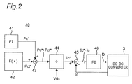
- FIG 2 is a flow diagram illustrating a control flow of the charge and discharge control unit 40 in the controller 10 of Figure 1 .
- the charge and discharge control unit 40 includes PI (proportional integral) controllers 41 and 46, a control function value output unit 42, an adder 43, a divider 44, and a subtractor 45.
- the PI controller 41 generates an output power instruction value Pc* (kW) for the capacitor 2 in accordance with the load 7 and outputs the output power instruction value Pc* to the adder 43.
- control function value output unit 42 calculates a function value Pet* (kW) of a temperature control function F ( ⁇ ) for the secondary battery 1, which will be described in detail below, and outputs the function value Pet* (kW) to the adder 43.
- the adder 43 adds up the two input values and outputs an added result, that is, an instruction value (Pc* + Pct*), to the divider 44.
- the divider 44 divides the input instruction value (Pc* + Pet*) by the voltage Vdc on the DC link 8 and outputs a divided result, that is, a primary-side current instruction value Ic* (A) for the capacitor 2, to the subtractor 45.
- the subtractor 45 subtracts a capacitor primary-side current value Ic (A) measured by the current detector 31 from the primary-side current instruction value Ic* for the capacitor 2 and outputs a subtracted result, that is, an error value (Ic* - Ic), to the PI controller 46.
- the PI controller 46 controls a duty factor D of the DC-DC converter 3 based on the error value (Ic* - Ic) so that the error value (Ic* - Ic) becomes 0.
- the primary-side current Ic of the capacitor 2 is a current on the reactor 4 and DC link 8 side and measured by the current detector 31.
- the charge and discharge control unit 40 of Figure 2 configured above is provided with: the PI controller 41 that uses the output power instruction value Pc* for the capacitor 2 depending on the load 7 as a controlled amount; and the PI controller 46 that uses the conduction ratio D of the DC-DC converter 3 depending on the primary-side current instruction value Ic* for the capacitor 2 as a controlled amount. Furthermore, the adder 43 adds an output power instruction value Pet* determined by the temperature control of the secondary battery 1 to the output power instruction value Pc* for the capacitor 2 depending on the load current Iac.
- the DC-DC converter 3 controls the primary-side current Ic of the capacitor 2 in accordance with the load current Iac on the AC side, indirectly controlling a current Ib of the secondary battery 1.
- the DC-DC converter 3 controls the voltage Vdc on the DC link 8 so as to become the same as the voltage Vb of the secondary battery 1.
- the temperature control function F ( ⁇ ) for the secondary battery 1 will be described below. Repeated charging and discharging between the secondary battery 1 and the capacitor 2 in order to increase the temperature is based on the temperature control function F ( ⁇ ).
- measurement values are as follows.
- the controller 10 estimates and calculates SOCs by using the voltage tables, but the present invention is not limited to this.
- the controller 10 may estimate and calculate the SOCs by using a current integrating method or other methods. Namely, the controller 10 can estimate and calculate the SOCs, based on a voltage of the secondary battery 1 or the capacitor 2 or a current thereof.
- a control rule of a temperature control process is as follows.
- a control rule of the secondary battery 1 is as follows.
- the controller 10 uses the following equation to determine a maximum discharging current Ib_discharge and a maximum charging current Ib_charge from the internal resistance Rb determined from the above (R1).
- V b_Min func 1 Soc b_Min ⁇ R b ⁇ I b_disch arg e
- V b_Max func 1 Soc b_Min + R b ⁇ I b_ch arg e
- the controller 10 uses the following equation to determine chargeable power Wb_charge (W) and dischargeable power Wb_discharge (W) from the voltage Vb (V) of the secondary battery 1, the number of cells interconnected in series Nb, and the number of cells interconnected in parallel Mb.
- W b_ch arg e V b ⁇ I b_ch arg e ⁇ N b ⁇ M b
- W b_disch arg e V b ⁇ I b_disch arg e ⁇ N b ⁇ M b
- a control rule of the capacitor 2 is as follows.
- the controller 10 uses the following equations to determine chargeable power Wc_charge (W) and dischargeable power Wc_discharge (W) from a capacitor voltage Vc (V), the number of cells interconnected in series Nc, and the number of cells interconnected in parallel Mc.
- W c_ch arg e V c ⁇ I c_ch arg e ⁇ N c ⁇ M c
- W c_disch arg e V c ⁇ I c_disch arg e ⁇ N c ⁇ M c
- control rules of the secondary battery 1 and the capacitor 2 are as follows.
- the control function value output unit 42 When determining the output power instruction value Pet* in the above manner, the control function value output unit 42 outputs the output power instruction value Pet* as a temperature control function value. Based on this, the charge and discharge control unit 40 of Figure 2 calculates a conduction ratio D and sets this conduction ratio D to the DC-DC converter 3, controlling a temperature Tb of the secondary battery 1.
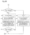
- Figures 3A and 3B are flowcharts each representing a process of controlling a temperature of the electricity storage device, the process being performed by the controller 10 of Figure 1 .
- step S1 of Figure 3A the controller 10 calculates a Socb of the secondary battery 1 with reference to a voltage table based on a voltage of the secondary battery 1.
- step S2 the controller 10 calculates a Socc of the capacitor 2 with reference to a voltage table based on a voltage of the capacitor 2.
- step S3 the controller 10 determines whether or not Socb > Socb_Min and Socc ⁇ Socc_Max. If the determination result is NO, the process proceeds to step S4 of Figure 3B . If the determination result is YES, the process proceeds to step S5.
- step S5 the controller 10 sets the capacitor charge instruction value Pct_charge* calculated using Equation 10 as the output power instruction value Pct*.
- step S6 the controller 10 sets the DC-DC converter 3 into the charging mode from the capacitor 2 to the secondary battery 1.
- step S7 the controller 10 causes the charge and discharge control unit 40 to perform the process of Figure 2 , calculating a duty factor D of the DC-DC converter 3. Based on this, the controller 10 controls the duty ratio, controlling a switching operation. Then, the process proceeds to step S8.
- step S8 the controller 10 determines whether Socb ⁇ Socb_Min or Socc > Socc_Max. If the determination result is NO, the process returns to step S5, and the DC-DC converter 3 continues to be in the charging mode. If the determination result is YES, the process returns to step S1.
- step S4 of Figure 3B the controller 10 determines whether or not Socb ⁇ Socb_Max and Socc > Socc_Min. If the determination result is NO, the process proceeds to step S 13. If the determination result is YES, the process proceeds to step S9. In step S9, the controller 10 sets the capacitor discharge instruction value Pct_discharge* calculated using Equation 11 as the output power instruction value Pct*. In step S10, the controller 10 sets the DC-DC converter 3 into the discharging mode from the secondary battery 1 to the capacitor 2. In step S11, the controller 10 causes the charge and discharge control unit 40 to perform the process of Figure 2 , calculating a duty factor D of the DC-DC converter 3. Based on this, the controller 10 controls the duty ratio, controlling the switching operation.
- step S12 the controller 10 determines whether Socb > Socb_Max or Socc ⁇ Socc_Min. If the determination result is NO, the process returns to step S9, and the DC-DC converter 3 continues to be in the discharging mode. If the determination result is YES, the process returns to step S1.
- step S13 the controller 10 sets the output power instruction value Pet* to 0.
- step S14 the controller 10 sets the DC-DC converter 3 into a stop mode.
- step S15 the controller 10 sets the duty factor D of the DC-DC converter 3 to 0, and stops the DC-DC converter 3. After the processing in step S15, the process returns to step S 1.
- Figure 4 is a graph of a capacitor SOC (Socc) in relation to a secondary battery SOC (Socb), illustrating regions of the charging mode, the discharging mode, and the stop mode, in the processes of controlling a temperature of the electricity storage device of Figures 3A and 3B .
- Socc capacitor SOC
- Socb secondary battery SOC
- the two-dimensional plane of Figure 4 is separated into four states (charging mode, discharging mode, stop mode, and either one of charging and discharging) by four SOC parameters (Socc_Max, Socc_Min, Socb_Max, and Socb_Min).
- the inventors of the present invention simulated a case of increasing a battery temperature Tb from 22 °C to 23 °C by using the electricity storage system of Figure 1 .
- Figures 5A to 5D and Figures 6A to 6D illustrate the results thereof.
- the conditions of this simulation were set as follows.
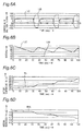
- Figures 5A to 5D illustrate simulation results of the electricity storage system of Figure 1 .
- Figure 5A is a waveform chart illustrating output power of each of a lithium ion battery (LiB) and a lithium ion capacitor (LiC) with elapsed time.
- Figure 5B is a waveform chart illustrating a voltage of each of the lithium ion battery (LiB) and the lithium ion capacitor (LiC) and a DC link voltage Vdc with elapsed time.
- Figure 5C is a waveform chart illustrating a current of each of the lithium ion battery (LiB) and the lithium ion capacitor (LiC) with elapsed time.
- Figure 5D is a waveform chart illustrating a cell voltage of each of the lithium ion battery (LiB) and the lithium ion capacitor (LiC) with elapsed time.
- Figure 6A to Figure 6D illustrate simulation results of the electricity storage system of Figure 1 .
- Figure 6A is a waveform chart illustrating a current upon one parallel row in each of the lithium ion battery (LiB) and the lithium ion capacitor (LiC) with elapsed time.
- Figure 6B is a waveform chart illustrating a SOC of each of the lithium ion battery (LiB) and the lithium ion capacitor (LiC) with elapsed time.
- Figure 6C is a waveform chart illustrating a battery temperature Tb of the lithium ion battery (LiB) with elapsed time.
- Figure 6D is a waveform chart illustrating an internal resistance Rrb of the lithium ion battery (LiB) with elapsed time.
- this implementation example enables the battery temperature to increase by 1°C in about 100 seconds. As can be understood from the above, it is possible to increase the temperature to a preset temperature at a maximum possible rate.
- an electricity storage system using a secondary battery 1 and a capacitor 2 in combination is constituted.
- This electricity storage system easily increases a temperature of the secondary battery 1 to a preset temperature at a maximum possible rate by controlling charging and discharging between the secondary battery 1 and the capacitor 2.
- electricity consumed during the increase in the temperature can be reduced to only charging and discharging efficiencies of the secondary battery and the capacitor.
- the secondary battery 1, such as a lithium ion battery is used as a first electricity storage device, but the present invention is not limited to this.
- a lead-acid battery, a nickel-cadmium battery, a nickel-hydrogen battery, and a lithium ion polymer battery may be used.
- a lithium ion capacitor is used as a second electricity storage device, but the present invention is not limited to this.
- an electric double-layer capacitor may be used.
- the electricity storage system including two electricity storage devices that is, the secondary battery 1 and the capacitor 2 has been described, but the present invention is not limited to this.
- An electricity storage system including three or more electricity storage devices may be constituted, and charging and discharging may be performed between the individual electricity storage devices.
- the AC load 7 is applicable to, for example, AC electrical equipment in an electric propulsion system for an AC motor in a vehicle, a vessel, or the like.
Landscapes
- Engineering & Computer Science (AREA)
- Power Engineering (AREA)
- Mechanical Engineering (AREA)
- Transportation (AREA)
- Chemical Kinetics & Catalysis (AREA)
- Electrochemistry (AREA)
- General Chemical & Material Sciences (AREA)
- Chemical & Material Sciences (AREA)
- Manufacturing & Machinery (AREA)
- Life Sciences & Earth Sciences (AREA)
- Sustainable Development (AREA)
- Sustainable Energy (AREA)
- Automation & Control Theory (AREA)
- Secondary Cells (AREA)
- Electric Propulsion And Braking For Vehicles (AREA)
- Charge And Discharge Circuits For Batteries Or The Like (AREA)
Abstract
Description
- The present invention relates to a temperature control apparatus and method for an electricity storage device, which are used for an electricity storage system including a plurality of electricity storage devices, and to an electricity storage system using the temperature control apparatus.
- There are some electricity storage devices whose internal resistances increase and thus charging and discharging capacities are lowered, with decreasing temperatures of the electricity storage devices. For example, as for the internal resistance with respect to a battery temperature of a typical lithium (Li) ion battery, the internal resistance when the battery is used at 10 °C is about 2.5 times greater than the internal resistance when the battery is used under an optimum temperature condition (25 °C). For this reason, when charging or discharging is performed at low temperatures, such a problem occurs that a voltage greatly decreases or increases to fall outside an operable battery voltage range, inhibiting a battery from outputting a desired amount of charging or discharging electricity. Two solutions to the problem with an inability to output a desired amount of charging or discharging electricity at low temperatures are as follows.
- The first solution is a method of setting a temperature of an electricity storage device to a preset temperature by warming up a neighborhood of the electricity storage device. For example, Chevrolet Volt plug-in hybrid vehicles are equipped with a refrigerant circuit for a battery. This refrigerant circuit functions to not only cool down the battery, but also heat the battery when an operation temperature decreases below an optimum range.
- In addition, the second solution disclosed in
Patent Document 1 is a method of forcibly performing charging or discharging within a predetermined charging range of an electricity storage device. In this second solution, heat generating as a result of the charging or discharging is used to control a temperature of the battery so as to become a preset temperature. When a temperature of the battery is lower than the preset temperature, charging or discharging is forcibly performed to feed current to the battery, and this leads to generation of heat from the internal resistance of the battery. - [Patent Document 1] Japanese Patent Laid-open Publication No.
JP2000-092614A - In the first solution, even when a vehicle is not moving, a controller still controls the refrigerant circuit. However, since the controller sets a temperature of the battery to a preset temperature by warming up the neighborhood of the battery, it may be impossible to promptly and easily increase a temperature of the battery to the preset temperature. In addition, the need for electricity supplied to the refrigerant circuit may turn out to be problematic.
- In the second solution, since the interior of the battery can be warmed up, it is possible to promptly increase a temperature of the battery to a preset temperature. However, there is such a problem that applying a load (engine output request) causes electricity stored in the battery to be consumed in vain.
- An object of the present invention is to address the above problems, and is to provide: a temperature control apparatus and method for an electricity storage device which are used for an electricity storage system using a plurality of electricity storage devices in combination, the apparatus and method capable of greatly decreasing power consumption in comparison with the prior art; and an electricity storage system using the temperature control apparatus.
- According to a first aspect of the present invention, there is provided a temperature control apparatus for an electricity storage device for use in an electricity storage system including a plurality of electricity storage devices including a first electricity storage device and a second electricity storage device. The first electricity storage device has a predetermined internal resistance. The temperature control apparatus includes a bidirectional DC-DC converter, temperature measurement means, and controller means. The bidirectional DC-DC converter is provided between the first electricity storage device and the second electricity storage device, so that the first electricity storage device is connected in parallel to the second electricity storage device through the bidirectional DC-DC converter and a DC link. The temperature measurement means is configured to measure a temperature of the first electricity storage device, and controller means is configured to control the temperature of the first electricity storage device. The controller means calculates a first SOC (State of Charge; referred to as SOC hereinafter) of the first electricity storage device, based on a voltage or a current of the first electricity storage device, and the controller means calculates a second SOC of the second electricity storage device, based on a voltage or a current of the second electricity storage device. When the first SOC is larger than a predetermined minimum value of the first SOC and the second SOC is smaller than a predetermined maximum value of the second SOC, the controller means sets the bidirectional DC-DC converter into a charging mode from the second electricity storage device to the first electricity storage device and controls the bidirectional DC-DC converter to operate in the charging mode. When the first SOC is smaller than a predetermined maximum value of the first SOC and the second SOC is larger than a predetermined minimum value of the second SOC, the controller means sets the bidirectional DC-DC converter into a discharging mode from the first electricity storage device to the second electricity storage device and controls the bidirectional DC-DC converter to operate in the discharging mode. The controller means calculates a conduction ratio D of the bidirectional DC-DC converter, based on the internal resistance of the first electricity storage device, the second SOC and a voltage on the DC link which are obtained when no load is connected to the DC link, and an error in a current of the bidirectional DC-DC converter on a DC link side, and then, the controller means controls the bidirectional DC-DC converter so that a conduction ratio of the bidirectional DC-DC converter becomes the conduction ratio D, thereby controlling the temperature of the first electricity storage device by using heat generating from the internal resistance of the first electricity storage device.
- Further, in the above-mentioned temperature control apparatus for the electricity storage device, the controller means calculates a first output power instruction value for the second electricity storage device, based on the internal resistance of the first electricity storage device and the second SOC which are obtained when no load is connected to the DC link, calculates a current instruction value for the bidirectional DC-DC converter on the DC link side, from the first output power instruction value and the voltage on the DC link, and calculates the conduction ratio D of the bidirectional DC-DC converter, based on the error between the current instruction value and the current of the bidirectional DC-DC converter on the DC link side.
- Furthermore, in the above-mentioned temperature control apparatus for the electricity storage device, the controller means calculates a second output power instruction value for the second electricity storage device in accordance with a load connected to the DC link, and then, controls the bidirectional DC-DC converter by adding the second output power instruction value to the first output power instruction value.
- According to a second aspect of the present invention, there is provided an electricity storage system including the temperature control apparatus for the electricity storage device for use in the electricity storage system, and a plurality of electricity storage devices including the first electricity storage device and the second electricity storage device.
- In the electricity storage system, the electricity storage system further includes a DC-AC inverter configured to convert a voltage on the DC link into an AC voltage.
- According to a third aspect of the present invention, there is provided a temperature control method for use in an electricity storage system including a plurality of electricity storage devices including a first electricity storage device and a second electricity storage device. The first electricity storage device has a predetermined internal resistance, and the method is performed by a temperature control apparatus for the electricity storage devices. The temperature control apparatus includes a bidirectional DC-DC converter, temperature measurement means, and controller means. The bidirectional DC-DC converter is provided between the first electricity storage device and the second electricity storage device, so that the first electricity storage device is connected in parallel to the second electricity storage device through the bidirectional DC-DC converter and a DC link. The temperature measurement means is configured to measure a temperature of the first electricity storage device, and the controller means is configured to control a temperature of the first electricity storage device. The temperature control method includes the following steps, which is performed by the controller means, of:
- calculating a first SOC of the first electricity storage device, based on a voltage or a current of the first electricity storage device;
- calculating a second SOC of the second electricity storage device, based on a voltage or a current of the second electricity storage device;
- when the first SOC is larger than a predetermined minimum value of the first SOC and the second SOC is smaller than a predetermined maximum value of the second SOC, setting the bidirectional DC-DC converter into a charging mode from the second electricity storage device to the first electricity storage device and controlling the bidirectional DC-DC converter to operate in the charging mode,
- when the first SOC is smaller than a predetermined maximum value of the first SOC and the second SOC is larger than a predetermined minimum value of the second SOC, setting the bidirectional DC-DC converter into a discharging mode from the first electricity storage device to the second electricity storage device and controlling the bidirectional DC-DC converter to operate in the discharging mode; and
- calculating a conduction ratio D of the bidirectional DC-DC converter, based on the internal resistance of the first electricity storage device, the second SOC, a voltage on the DC link which are obtained when no load is connected to the DC link, and an error in a current of the bidirectional DC-DC converter on a DC link side, and then, controlling the bidirectional DC-DC converter so that a conduction ratio of the bidirectional DC-DC converter becomes the conduction ratio D, thereby controlling the temperature of the first electricity storage device in accordance with a variation in the internal resistance of the first electricity storage device.
- According to the present invention, a temperature control apparatus and method for an electricity storage device which are used for an electricity storage system using a plurality of electricity storage devices in combination control charging and discharging between these electricity storage devices, thus promptly and easily increasing an temperature of each of the electricity storage devices to a preset temperature and not consuming electricity in vain during an increase in the temperature. Therefore, it is possible to greatly decrease the power consumption in comparison with the prior art.
-
-
Figure 1 is a block diagram illustrating a configuration of an electricity storage system according to an embodiment of the present invention. -
Figure 2 is a flow diagram illustrating a control flow of a charge anddischarge control unit 40 in acontroller 10 ofFigure 1 . -
Figure 3A is a flowchart representing a first part of a process of controlling a temperature of the electricity storage device, the process being performed by thecontroller 10 ofFigure 1 . -
Figure 3B is a flowchart representing a second part of the process of controlling a temperature of the electricity storage device, the process being performed by thecontroller 10 ofFigure 1 . -
Figure 4 is a graph of a capacitor SOC (Socc) in relation to a secondary battery SOC (Socb), illustrating regions of a charging mode and a discharging mode in the process of controlling a temperature of the electricity storage device ofFigures 3A and 3B . -
Figure 5A illustrates a simulation result of the electricity storage system ofFigure 1 and is a waveform chart illustrating output power of each of a lithium ion battery (LiB) and a lithium ion capacitor (LiC) with elapsed time. -
Figure 5B illustrates a simulation result of the electricity storage system ofFigure 1 and is a waveform chart illustrating a voltage of each of the lithium ion battery (LiB) and the lithium ion capacitor (LiC) and a DC link voltage Vdc with elapsed time. -
Figure 5C illustrates a simulation result of the electricity storage system ofFigure 1 and is a waveform chart illustrating a current of each of the lithium ion battery (LiB) and the lithium ion capacitor (LiC) with elapsed time. -
Figure 5D illustrates a simulation result of the electricity storage system ofFigure 1 and is a waveform chart illustrating a cell voltage of each of the lithium ion battery (LiB) and the lithium ion capacitor (LiC) with elapsed time. -
Figure 6A illustrates a simulation result of the electricity storage system ofFigure 1 and is a waveform chart illustrating a current upon one parallel row in each of the lithium ion battery (LiB) and the lithium ion capacitor (LiC) with elapsed time. -
Figure 6B illustrates a simulation result of the electricity storage system ofFigure 1 and is a waveform chart illustrating a SOC of each of the lithium ion battery (LiB) and the lithium ion capacitor (LiC) with elapsed time. -
Figure 6C illustrates a simulation result of the electricity storage system ofFigure 1 and is a waveform chart illustrating a battery temperature Tb of the lithium ion battery (LiB) with elapsed time. -
Figure 6D illustrates a simulation result of the electricity storage system ofFigure 1 and is a waveform chart illustrating an internal resistance Rrb of the lithium ion battery (LiB) with elapsed time. - Some embodiments of the present invention will be described below with reference to the accompanying drawings. It should be noted that in the following embodiments, the same reference characters are given to similar constituent elements.
-
Figure 1 is a block diagram illustrating a configuration of an electricity storage system according to an embodiment of the present invention. The electricity storage system ofFigure 1 includes: asecondary battery 1 having an internal resistance Rb such as a lithium ion battery; acapacitor 2 having an internal resistance Rc such as a lithium ion capacitor; a bidirectional buck-boost DC-DC converter (referred to as a DC-DC converter hereinafter) 3; a smoothing reactor (referred to as a reactor hereinafter) 4; afilter capacitor 5; a DC-AC inverter 6; and aload 7. In this case, thesecondary battery 1 is constituted by connecting an Nb number of cells in series to form an Mb number of series circuits and connecting the series circuits in parallel. Thecapacitor 2 is constituted by connecting an Nc number of cells in series to form an Mc number of series circuits and connecting the series circuits in parallel. Thesecondary battery 1 is connected in parallel to thecapacitor 2 on a DC link 8 through the DC-DC converter 3 and thereactor 4. The DC-DC converter 3 has a charging mode of charging thecapacitor 2 with electricity and a discharging mode of discharging electricity from thecapacitor 2. The DC-DC converter 3 makes a bidirectional DC-DC conversion between thecapacitor 2 and the DC link 8, and can change individual DC voltages by boosting or bucking the DC voltages. These operations are controlled by thecontroller 10. A DC voltage on the DC link 8 is DC-to-AC-converted into an AC voltage by the DC-AC inverter 6, and the AC voltage is outputted to theAC load 7. - Referring to
Figure 1 , avoltage detector 11 is provided in thesecondary battery 1 in order to measure a voltage Vb of thesecondary battery 1, and atemperature measurement instrument 13 is provided in order to measure a battery temperature Tb of thesecondary battery 1. In addition, avoltage detector 21 is provided in thecapacitor 2 in order to measure a voltage Vc of thecapacitor 2. Further, acurrent detector 31 is provided in order to measure a current of thereactor 4. Avoltage detector 51 is provided in order to measure a voltage Vdc on the DC link 8. Information regarding voltages measured by thevoltage detectors current detector 31 is outputted to thecontroller 10. Thecontroller 10 is based on the input information and has a charge anddischarge control unit 40 ofFigure 2 and atable memory 10m. Thetable memory 10m stores individual voltage tables (tables showing relationships between voltages and SOCs), which are used to estimate and calculate a SOC of thesecondary battery 1 and a SOC of thecapacitor 2, for example, in a voltage table method. Thecontroller 10 controls an operation mode of the DC-DC converter 3 and a conduction ratio D of the DC-DC converter 3 by performing processes of controlling a temperature of an electricity storage device ofFigures 3A and 3B , thus controlling a temperature of thesecondary battery 1. In this case, a duty ratio of the DC-DC converter 3 is determined based on the conduction ratio D. -
Figure 2 is a flow diagram illustrating a control flow of the charge anddischarge control unit 40 in thecontroller 10 ofFigure 1 . Referring toFigure 2 , the charge anddischarge control unit 40 includes PI (proportional integral)controllers value output unit 42, anadder 43, adivider 44, and asubtractor 45. ThePI controller 41 generates an output power instruction value Pc* (kW) for thecapacitor 2 in accordance with theload 7 and outputs the output power instruction value Pc* to theadder 43. In addition, the control functionvalue output unit 42 calculates a function value Pet* (kW) of a temperature control function F (·) for thesecondary battery 1, which will be described in detail below, and outputs the function value Pet* (kW) to theadder 43. Theadder 43 adds up the two input values and outputs an added result, that is, an instruction value (Pc* + Pct*), to thedivider 44. Thedivider 44 divides the input instruction value (Pc* + Pet*) by the voltage Vdc on the DC link 8 and outputs a divided result, that is, a primary-side current instruction value Ic* (A) for thecapacitor 2, to thesubtractor 45. Thesubtractor 45 subtracts a capacitor primary-side current value Ic (A) measured by thecurrent detector 31 from the primary-side current instruction value Ic* for thecapacitor 2 and outputs a subtracted result, that is, an error value (Ic* - Ic), to thePI controller 46. ThePI controller 46 controls a duty factor D of the DC-DC converter 3 based on the error value (Ic* - Ic) so that the error value (Ic* - Ic) becomes 0. It should be noted that the primary-side current Ic of thecapacitor 2 is a current on thereactor 4 and DC link 8 side and measured by thecurrent detector 31. - In order to deal with a load current Iac on an AC side, basically, the charge and
discharge control unit 40 ofFigure 2 configured above is provided with: thePI controller 41 that uses the output power instruction value Pc* for thecapacitor 2 depending on theload 7 as a controlled amount; and thePI controller 46 that uses the conduction ratio D of the DC-DC converter 3 depending on the primary-side current instruction value Ic* for thecapacitor 2 as a controlled amount. Furthermore, theadder 43 adds an output power instruction value Pet* determined by the temperature control of thesecondary battery 1 to the output power instruction value Pc* for thecapacitor 2 depending on the load current Iac. In the present embodiment, basically, the DC-DC converter 3 controls the primary-side current Ic of thecapacitor 2 in accordance with the load current Iac on the AC side, indirectly controlling a current Ib of thesecondary battery 1. The DC-DC converter 3 controls the voltage Vdc on the DC link 8 so as to become the same as the voltage Vb of thesecondary battery 1. - Next, a description will be given below of a basic logic of temperature control of a secondary battery.
-
- (1) If the
load 7 on the AC side is absent, the control functionvalue output unit 42 uses the temperature control function F (·) of thesecondary battery 1 to generate an output power instruction value Pet* for thecapacitor 2 from, for example, an internal resistance Rb and a SOC of thecapacitor 2 which are calculated based on a battery temperature (measurement value) Tb of thesecondary battery 1. - (2) The
divider 44 uses the output power instruction value Pet* and a DC link voltage Vdc to determine a primary-side capacitor current instruction value Ic* for the DC-DC converter 3. Then, thePI controller 46 determines a conduction ratio D of the DC-DC converter 3 as an output of thecontroller 10. As a result, a primary-side capacitor current Ic flows through the DC-DC converter 3. Since theload 7 on the AC side is absent, a current flows between thecapacitor 2 and thesecondary battery 1, causing charging and discharging. Heat generating in the internal resistance Rb in thesecondary battery 1 increases a temperature of thesecondary battery 1. - (3) If the
load 7 occurs during an increase in the temperature, the charge anddischarge control unit 40 stops the charging and discharging for increasing the temperature. Then, thePI controller 41 that outputs an output power instruction value Pc* controls the same by tracking with bumpless so as to be able to supply electricity to theload 7. - Subsequently, the temperature control function F (·) for the
secondary battery 1 will be described below. Repeated charging and discharging between thesecondary battery 1 and thecapacitor 2 in order to increase the temperature is based on the temperature control function F (·). - First of all, the preconditions are as follows.
- (1) A charge and discharge range of the
secondary battery 1 is set to a range from a minimum value Socb_Min of a SOC to a maximum value Socb_Max (%) thereof. Typically, if a lifetime of thesecondary battery 1 is taken into consideration, thesecondary battery 1 preferably has a shallow depth of charge and discharge, which is in a range of approximately 10 %. - (2) A charge and discharge range of the
capacitor 2 is set to a range from a minimum value Socc_Min of a SOC to a maximum value Socc_Max (%) thereof. Typically, thecapacitor 2 can have a great depth of charge and discharge. - (3) The internal resistance Rc of the
capacitor 2 is set to a constant value Rc (Ω), because the internal resistance Rc does not largely depend on a temperature of thecapacitor 2. - (4) An allowable range of a terminal voltage of the
secondary battery 1 is set to a range from a minimum value Vb_Min to a maximum value Vb_Max (V). - (5) An allowable range of a terminal voltage of the
capacitor 2 is set to a range from a minimum value Vc_Min to a maximum value Vc_Max (V). - Then, electrical characteristics of the
secondary battery 1 prepared herein are as follows. - (1) Charging and discharging characteristics (Socb (%) - internal electromotive force Eb (V)): Eb = func1 (Socb); and
- (2) Temperature characteristics (battery temperature (measurement value) Tb (°C) - internal resistance Rb (Ω)): Rb = func2 (Tb).
- In this case, measurement values (including estimated, calculated values) are as follows.
- (1) A battery temperature Tb (°C) of the secondary battery 1: it is measured by the
temperature measurement instrument 13. - (2) A voltage Vb (V) of the secondary battery 1: it is measured by the
voltage detector 11. - (3) A voltage Vc (V) of the capacitor 2: it is measured by the
voltage detector 21. - (4) A voltage Vdc (V) on the DC link 8: it is measured by the
voltage detector 51. - (5) A SOC (Socb) (%) of the secondary battery 1: it is estimated and calculated by the
controller 10, based on a voltage Vb (measurement value) of thesecondary battery 1; thecontroller 10 uses a known voltage table method and refers to a voltage table in thetable memory 10m. - (6) A SOC (Socc) (%) of the capacitor 2: it is estimated and calculated by the
controller 10, based on a voltage Vc (measurement value) of thecapacitor 2; thecontroller 10 uses a known voltage table method and refers to a voltage table in thetable memory 10m. - It should be noted that in the present embodiment, the
controller 10 estimates and calculates SOCs by using the voltage tables, but the present invention is not limited to this. Thecontroller 10 may estimate and calculate the SOCs by using a current integrating method or other methods. Namely, thecontroller 10 can estimate and calculate the SOCs, based on a voltage of thesecondary battery 1 or thecapacitor 2 or a current thereof. - Moreover, a control rule of a temperature control process is as follows.
- First of all, a control rule of the
secondary battery 1 is as follows. - (R1) The
controller 10 determines an internal resistance Rb (Ω) of thesecondary battery 1 at a temperature Tb (°C) from the temperature characteristic Rb = func2 (Tb). - (R2) The
controller 10 uses the following equation to determine a maximum discharging current Ib_discharge and a maximum charging current Ib_charge from the internal resistance Rb determined from the above (R1).
[Equation 1]

- (R3) The
controller 10 uses the following equation to determine chargeable power Wb_charge (W) and dischargeable power Wb_discharge (W) from the voltage Vb (V) of thesecondary battery 1, the number of cells interconnected in series Nb, and the number of cells interconnected in parallel Mb.
[Equation 3]

- Then, a control rule of the
capacitor 2 is as follows. - (R11) A capacitance of the
capacitor 2 is denoted by C (F); the relationship between a SOC (Socc) and a charge quantity Q of the capacitor is given as follows.
[Equation 5]
- Therefore, if a charge and discharge range of the
capacitor 2 is set to a range from the minimum value Socc_Min of a SOC to the maximum value Socc_Max (%) thereof, thecontroller 10 can determine a minimum value Q_Min of the charge quantity and a maximum value Q_Max of the charge quantity. Then, thecontroller 10 determines a maximum discharging current Ic_discharge and a maximum charging current Ic_charge by using the following equation.
[Equation 6]

- (R12) The
controller 10 uses the following equations to determine chargeable power Wc_charge (W) and dischargeable power Wc_discharge (W) from a capacitor voltage Vc (V), the number of cells interconnected in series Nc, and the number of cells interconnected in parallel Mc.
[Equation 8]

- Further, control rules of the
secondary battery 1 and thecapacitor 2 are as follows. - (R21) The power instruction value Pet* is expressed by two values, that is, a capacitor charge instruction value Pct_charge* and a capacitor discharge instruction value Pct_discharge*, which can be determined from the following equations. It should be noted that min (A, B) is a minimum function through which a smaller value of A and B is set to a function value.
[Equation 10]

- (R22) The output power instruction value Pet* is switched over in accordance with the following conditions C1 and C2.
Condition C1:
[Equation 12]
[Equation 13]
Condition C2:
[Equation 14]
[Equation 15]
- (R23) When determining the output power instruction value Pet* in the above manner, the control function
value output unit 42 outputs the output power instruction value Pet* as a temperature control function value. Based on this, the charge anddischarge control unit 40 ofFigure 2 calculates a conduction ratio D and sets this conduction ratio D to the DC-DC converter 3, controlling a temperature Tb of thesecondary battery 1. -
Figures 3A and 3B are flowcharts each representing a process of controlling a temperature of the electricity storage device, the process being performed by thecontroller 10 ofFigure 1 . - In step S1 of
Figure 3A , thecontroller 10 calculates a Socb of thesecondary battery 1 with reference to a voltage table based on a voltage of thesecondary battery 1. In step S2, thecontroller 10 calculates a Socc of thecapacitor 2 with reference to a voltage table based on a voltage of thecapacitor 2. Then, in step S3, thecontroller 10 determines whether or not Socb > Socb_Min and Socc < Socc_Max. If the determination result is NO, the process proceeds to step S4 ofFigure 3B . If the determination result is YES, the process proceeds to step S5. In step S5, thecontroller 10 sets the capacitor charge instruction value Pct_charge* calculated usingEquation 10 as the output power instruction value Pct*. In step S6, thecontroller 10 sets the DC-DC converter 3 into the charging mode from thecapacitor 2 to thesecondary battery 1. In step S7, thecontroller 10 causes the charge anddischarge control unit 40 to perform the process ofFigure 2 , calculating a duty factor D of the DC-DC converter 3. Based on this, thecontroller 10 controls the duty ratio, controlling a switching operation. Then, the process proceeds to step S8. In step S8, thecontroller 10 determines whether Socb < Socb_Min or Socc > Socc_Max. If the determination result is NO, the process returns to step S5, and the DC-DC converter 3 continues to be in the charging mode. If the determination result is YES, the process returns to step S1. - In step S4 of
Figure 3B , thecontroller 10 determines whether or not Socb < Socb_Max and Socc > Socc_Min. If the determination result is NO, the process proceeds to stepS 13. If the determination result is YES, the process proceeds to step S9. In step S9, thecontroller 10 sets the capacitor discharge instruction value Pct_discharge* calculated usingEquation 11 as the output power instruction value Pct*. In step S10, thecontroller 10 sets the DC-DC converter 3 into the discharging mode from thesecondary battery 1 to thecapacitor 2. In step S11, thecontroller 10 causes the charge anddischarge control unit 40 to perform the process ofFigure 2 , calculating a duty factor D of the DC-DC converter 3. Based on this, thecontroller 10 controls the duty ratio, controlling the switching operation. Then, the process proceeds to step S 12. In step S12, thecontroller 10 determines whether Socb > Socb_Max or Socc < Socc_Min. If the determination result is NO, the process returns to step S9, and the DC-DC converter 3 continues to be in the discharging mode. If the determination result is YES, the process returns to step S1. In step S13, thecontroller 10 sets the output power instruction value Pet* to 0. In step S14, thecontroller 10 sets the DC-DC converter 3 into a stop mode. In step S15, thecontroller 10 sets the duty factor D of the DC-DC converter 3 to 0, and stops the DC-DC converter 3. After the processing in step S15, the process returns to stepS 1. -
Figure 4 is a graph of a capacitor SOC (Socc) in relation to a secondary battery SOC (Socb), illustrating regions of the charging mode, the discharging mode, and the stop mode, in the processes of controlling a temperature of the electricity storage device ofFigures 3A and 3B . As can be seen fromFigure 4 , in this control method, the two-dimensional plane ofFigure 4 is separated into four states (charging mode, discharging mode, stop mode, and either one of charging and discharging) by four SOC parameters (Socc_Max, Socc_Min, Socb_Max, and Socb_Min). When Socb > Socb_Max and Socc > Socc_Max, both the electricity storage devices exceed the maximum SOCs, and thus DC-DC converter 3 is set into the stop mode. In addition, when Socb < Socb_Min and Socc > Socc_Min, both the electricity storage devices are less than the minimum SOCs, and thus DC-DC converter 3 is set into the stop mode, too. In the other regions, when Socb > Socb_Min and Socc < Socc_Max, the DC-DC converter 3 is set into the charging mode, and when Socb < Socb_Max and Socc > Socc_Min, the DC-DC converter 3 is set into the discharging mode. In the region where the charging mode overlaps the discharging mode, either one of charging and discharging is allowed, and thus, the DC-DC converter 3 is set into either one of the charging mode and the discharging mode. - The inventors of the present invention simulated a case of increasing a battery temperature Tb from 22 °C to 23 °C by using the electricity storage system of
Figure 1 .Figures 5A to 5D andFigures 6A to 6D illustrate the results thereof. The conditions of this simulation were set as follows. - (1) The setting range from Socb_Min to Socb_Max (%) of the SOC of the secondary battery 1: 40 to 50 %;
- (2) The setting range from Socc_Min to Socc_Max (%) of the SOC of the capacitor 2: 70 to 90 %;
- (3) The setting range from Vb_Min to Vb_Max (V) of the voltage Vb of the secondary battery 1: 2.5 to 3.5 V/cell;
- (4) The setting range from Vc_Min to Vc_Max (V) of the voltage Vc of the capacitor 2: 2.2 to 3.8 V/cell;
- (5) Voltage Vb of
secondary battery 1 = 950.544 V; - (6) The
secondary battery 1 was constituted by connecting 288 cells in series to form five series circuits and connecting these series circuits in parallel; - (7) Voltage Vc of
capacitor 2 = 729.6 V; - (8) The
capacitor 2 was constituted by connecting 192 cells in series to form five series circuits and connecting these series circuits in parallel; - (9) Capacitor discharge instruction value Pct_discharge* = 150 kW;
- (10) Capacitor charge instruction value Pct_charge* = 400 kW; and
- (11) The
secondary battery 1 had a heat capacity Cb (1603 J/K/cell) expressed by the following equations. -
Figures 5A to 5D illustrate simulation results of the electricity storage system ofFigure 1 .Figure 5A is a waveform chart illustrating output power of each of a lithium ion battery (LiB) and a lithium ion capacitor (LiC) with elapsed time.Figure 5B is a waveform chart illustrating a voltage of each of the lithium ion battery (LiB) and the lithium ion capacitor (LiC) and a DC link voltage Vdc with elapsed time.Figure 5C is a waveform chart illustrating a current of each of the lithium ion battery (LiB) and the lithium ion capacitor (LiC) with elapsed time.Figure 5D is a waveform chart illustrating a cell voltage of each of the lithium ion battery (LiB) and the lithium ion capacitor (LiC) with elapsed time. In addition,Figure 6A to Figure 6D illustrate simulation results of the electricity storage system ofFigure 1 .Figure 6A is a waveform chart illustrating a current upon one parallel row in each of the lithium ion battery (LiB) and the lithium ion capacitor (LiC) with elapsed time.Figure 6B is a waveform chart illustrating a SOC of each of the lithium ion battery (LiB) and the lithium ion capacitor (LiC) with elapsed time.Figure 6C is a waveform chart illustrating a battery temperature Tb of the lithium ion battery (LiB) with elapsed time.Figure 6D is a waveform chart illustrating an internal resistance Rrb of the lithium ion battery (LiB) with elapsed time. - As can be seen from
Figure 5A to Figure 5D andFigure 6A to Figure 6D , this implementation example enables the battery temperature to increase by 1°C in about 100 seconds. As can be understood from the above, it is possible to increase the temperature to a preset temperature at a maximum possible rate. - As described above, according to the present embodiment, an electricity storage system using a
secondary battery 1 and acapacitor 2 in combination is constituted. This electricity storage system easily increases a temperature of thesecondary battery 1 to a preset temperature at a maximum possible rate by controlling charging and discharging between thesecondary battery 1 and thecapacitor 2. In addition, electricity consumed during the increase in the temperature can be reduced to only charging and discharging efficiencies of the secondary battery and the capacitor. - In the embodiments described above, the
secondary battery 1, such as a lithium ion battery, is used as a first electricity storage device, but the present invention is not limited to this. Alternatively, for example, a lead-acid battery, a nickel-cadmium battery, a nickel-hydrogen battery, and a lithium ion polymer battery may be used. In addition, for example, a lithium ion capacitor is used as a second electricity storage device, but the present invention is not limited to this. Alternatively, for example, an electric double-layer capacitor may be used. - In the embodiments described above, the electricity storage system including two electricity storage devices, that is, the
secondary battery 1 and thecapacitor 2, has been described, but the present invention is not limited to this. An electricity storage system including three or more electricity storage devices may be constituted, and charging and discharging may be performed between the individual electricity storage devices. - As described above in detail, it is possible to provide a temperature control apparatus and method for an electricity storage device which are used for an electricity storage system using a plurality of electricity storage devices in combination, the apparatus and method capable of greatly decreasing power consumption in comparison with the prior art. The
AC load 7 is applicable to, for example, AC electrical equipment in an electric propulsion system for an AC motor in a vehicle, a vessel, or the like. -
- 1:
- secondary battery
- 2:
- capacitor
- 3:
- bidirectional buck-boost dc-dc converter (dc-dc converter)
- 4:
- smoothing reactor
- 5:
- filter capacitor
- 6:
- dc-ac inverter
- 7:
- load
- 10:
- controller
- 10m:
- table memory
- 11, 21 and 51:
- voltage detector
- 31:
- current detector
- 13:
- temperature measurement instrument
- 40:
- charge and discharge control unit
- 41 and 46:
- PI controller
- 42:
- control function value output unit
- 43:
- adder
- 44:
- divider
- 45:
- subtractor


Claims (6)
- A temperature control apparatus for an electricity storage device for use in an electricity storage system including a plurality of electricity storage devices including a first electricity storage device and a second electricity storage device, the first electricity storage device having a predetermined internal resistance, the temperature control apparatus comprising:a bidirectional DC-DC converter provided between the first electricity storage device and the second electricity storage device, so that the first electricity storage device is connected in parallel to the second electricity storage device through the bidirectional DC-DC converter and a DC link;temperature measurement means configured to measure a temperature of the first electricity storage device; andcontroller means configured to control the temperature of the first electricity storage device,wherein the controller means calculates a first SOC of the first electricity storage device, based on a voltage or a current of the first electricity storage device,
wherein the controller means calculates a second SOC of the second electricity storage device, based on a voltage or a current of the second electricity storage device,
wherein, when the first SOC is larger than a predetermined minimum value of the first SOC and the second SOC is smaller than a predetermined maximum value of the second SOC, the controller means sets the bidirectional DC-DC converter into a charging mode from the second electricity storage device to the first electricity storage device and controls the bidirectional DC-DC converter to operate in the charging mode,
wherein, when the first SOC is smaller than a predetermined maximum value of the first SOC and the second SOC is larger than a predetermined minimum value of the second SOC, the controller means sets the bidirectional DC-DC converter into a discharging mode from the first electricity storage device to the second electricity storage device and controls the bidirectional DC-DC converter to operate in the discharging mode, and
wherein, the controller means calculates a conduction ratio D of the bidirectional DC-DC converter, based on the internal resistance of the first electricity storage device, the second SOC and a voltage on the DC link which are obtained when no load is connected to the DC link, and an error in a current of the bidirectional DC-DC converter on a DC link side, and then, the controller means controls the bidirectional DC-DC converter so that a conduction ratio of the bidirectional DC-DC converter becomes the conduction ratio D, thereby controlling the temperature of the first electricity storage device by using heat generating from the internal resistance of the first electricity storage device. - The temperature control apparatus for the electricity storage device for use in the electricity storage system, as claimed in claim 1,
wherein the controller means calculates a first output power instruction value for the second electricity storage device, based on the internal resistance of the first electricity storage device and the second SOC which are obtained when no load is connected to the DC link, calculates a current instruction value for the bidirectional DC-DC converter on the DC link side, from the first output power instruction value and the voltage on the DC link, and calculates the conduction ratio D of the bidirectional DC-DC converter, based on the error between the current instruction value and the current of the bidirectional DC-DC converter on the DC link side. - The temperature control apparatus for the electricity storage device for use in the electricity storage system as claimed in claim 2,
wherein the controller means calculates a second output power instruction value for the second electricity storage device in accordance with a load connected to the DC link, and then, controls the bidirectional DC-DC converter by adding the second output power instruction value to the first output power instruction value. - An electricity storage system comprising:the temperature control apparatus for the electricity storage device for use in the electricity storage system, as claimed in any one of claims 1 to 3; anda plurality of electricity storage devices including the first electricity storage device and the second electricity storage device.
- The electricity storage system as claimed in claim 4, further comprising a DC-AC inverter that converts a voltage on the DC link into an AC voltage.
- A temperature control method for use in an electricity storage system including a plurality of electricity storage devices including a first electricity storage device and a second electricity storage device, the first electricity storage device having a predetermined internal resistance, the method being performed by a temperature control apparatus for the electricity storage devices,
wherein the temperature control apparatus comprising:a bidirectional DC-DC converter provided between the first electricity storage device and the second electricity storage device, so that the first electricity storage device is connected in parallel to the second electricity storage device through the bidirectional DC-DC converter and a DC link;temperature measurement means configured to measure a temperature of the first electricity storage device; andcontroller means configured to control a temperature of the first electricity storage device,wherein the temperature control method comprising the following steps, being performed by the controller means, of:calculating a first SOC of the first electricity storage device, based on a voltage or a current of the first electricity storage device;calculating a second SOC of the second electricity storage device, based on a voltage or a current of the second electricity storage device;when the first SOC is larger than a predetermined minimum value of the first SOC and the second SOC is smaller than a predetermined maximum value of the second SOC, setting the bidirectional DC-DC converter into a charging mode from the second electricity storage device to the first electricity storage device and controlling the bidirectional DC-DC converter to operate in the charging mode,when the first SOC is smaller than a predetermined maximum value of the first SOC and the second SOC is larger than a predetermined minimum value of the second SOC, setting the bidirectional DC-DC converter into a discharging mode from the first electricity storage device to the second electricity storage device and controlling the bidirectional DC-DC converter to operate in the discharging mode; andcalculating a conduction ratio D of the bidirectional DC-DC converter, based on the internal resistance of the first electricity storage device, the second SOC, a voltage on the DC link which are obtained when no load is connected to the DC link, and an error in a current of the bidirectional DC-DC converter on a DC link side, and then, controlling the bidirectional DC-DC converter so that a conduction ratio of the bidirectional DC-DC converter becomes the conduction ratio D, thereby controlling the temperature of the first electricity storage device in accordance with a variation in the internal resistance of the first electricity storage device.
Applications Claiming Priority (2)
| Application Number | Priority Date | Filing Date | Title |
|---|---|---|---|
| JP2013269206A JP2015125880A (en) | 2013-12-26 | 2013-12-26 | Temperature control unit and method for power storage device, and power storage system |
| PCT/JP2014/084559 WO2015099138A1 (en) | 2013-12-26 | 2014-12-26 | Temperature control apparatus for electricity storage device |
Publications (2)
| Publication Number | Publication Date |
|---|---|
| EP3089256A1 true EP3089256A1 (en) | 2016-11-02 |
| EP3089256A4 EP3089256A4 (en) | 2017-08-16 |
Family
ID=53478977
Family Applications (1)
| Application Number | Title | Priority Date | Filing Date |
|---|---|---|---|
| EP14873252.2A Withdrawn EP3089256A4 (en) | 2013-12-26 | 2014-12-26 | Temperature control apparatus for electricity storage device |
Country Status (5)
| Country | Link |
|---|---|
| US (1) | US9975447B2 (en) |
| EP (1) | EP3089256A4 (en) |
| JP (1) | JP2015125880A (en) |
| CA (1) | CA2935019A1 (en) |
| WO (1) | WO2015099138A1 (en) |
Cited By (3)
| Publication number | Priority date | Publication date | Assignee | Title |
|---|---|---|---|---|
| EP3447872A1 (en) * | 2017-08-21 | 2019-02-27 | Fuji Electric Co., Ltd. | Power fluctuation mitigation system |
| EP3490053A1 (en) * | 2017-11-28 | 2019-05-29 | Ningbo Geely Automobile Research & Development Co. Ltd. | Internal heating of a battery |
| CN111231677A (en) * | 2020-01-22 | 2020-06-05 | 东风汽车集团有限公司 | A kind of testing method and system for pure electric vehicle energy flow |
Families Citing this family (32)
| Publication number | Priority date | Publication date | Assignee | Title |
|---|---|---|---|---|
| US9929449B2 (en) * | 2014-06-10 | 2018-03-27 | Vertiv Energy Systems, Inc. | Systems and methods for warming batteries |
| US9809119B2 (en) * | 2015-01-13 | 2017-11-07 | General Electric Company | Bi-directional DC-DC power converter for a vehicle system |
| JP6527785B2 (en) * | 2015-08-19 | 2019-06-05 | 本田技研工業株式会社 | Drive device and transportation equipment |
| JP6531010B2 (en) * | 2015-08-19 | 2019-06-12 | 本田技研工業株式会社 | DRIVE DEVICE, TRANSPORT EQUIPMENT, AND STORAGE DEVICE CONTROL METHOD |
| JP2017041974A (en) * | 2015-08-19 | 2017-02-23 | 本田技研工業株式会社 | DRIVE DEVICE, ITS CONTROL METHOD, AND TRANSPORTATION DEVICE |
| JP2017085754A (en) | 2015-10-27 | 2017-05-18 | 本田技研工業株式会社 | Power storage device, transport device and control method |
| DE102016205333A1 (en) * | 2016-03-31 | 2017-10-05 | Siemens Aktiengesellschaft | Method and device for tempering a rechargeable battery |
| DE102017002483A1 (en) * | 2017-03-15 | 2018-09-20 | Man Truck & Bus Ag | Technique for insulation monitoring in vehicles |
| US10875397B2 (en) * | 2017-06-30 | 2020-12-29 | Hamilton Sundstrand Corporation | HESM fast recharge algorithm |
| DE102018102211B3 (en) * | 2018-02-01 | 2019-09-19 | Dr. Ing. H.C. F. Porsche Aktiengesellschaft | Battery system for a battery powered electric vehicle and method for utilizing a remaining range thereof |
| WO2020049943A1 (en) * | 2018-09-05 | 2020-03-12 | 住友電気工業株式会社 | Secondary battery temperature-raising device, computer program, and secondary battery temperature-raising method |
| CN109786868B (en) * | 2018-12-13 | 2020-11-06 | 北京理工大学 | A method, system and device for processing thermal runaway of electric ship battery system |
| KR102731551B1 (en) * | 2019-03-04 | 2024-11-18 | 현대자동차주식회사 | System and method for controlling battery charging or discharging |
| CN109950660B (en) * | 2019-03-25 | 2022-01-18 | 清华大学 | Method for preheating ternary lithium ion power battery by utilizing self energy storage excitation |
| CN109904540B (en) * | 2019-03-25 | 2022-03-04 | 哈尔滨理工大学 | A low-temperature alternating excitation preheating method for lithium iron phosphate power battery |
| CN109950661B (en) * | 2019-03-25 | 2022-04-12 | 清华大学 | Device and method for simultaneously heating inside and outside of power battery pack |
| EP3859870A4 (en) * | 2019-10-21 | 2022-06-15 | Ningde Amperex Technology Ltd. | CHARGING PROCESS, ELECTRONIC DEVICE AND STORAGE MEDIA |
| CN110828918B (en) * | 2019-11-13 | 2023-03-24 | 奇瑞新能源汽车股份有限公司 | Control system and control method for automobile power battery |
| CN110920393B (en) * | 2019-11-27 | 2021-07-23 | 浙江合众新能源汽车有限公司 | A low-voltage power supply system for an electric vehicle and a charging and discharging method for a low-voltage lithium battery |
| US11967855B2 (en) | 2019-12-31 | 2024-04-23 | Ways Technical Corp., Ltd | Capacitor device used in energy storage system |
| US11901762B2 (en) | 2019-12-31 | 2024-02-13 | Ways Technical Corp., Ltd. | Energy storage system |
| TWI780392B (en) * | 2019-12-31 | 2022-10-11 | 位速科技股份有限公司 | energy storage system |
| CN113162205B (en) * | 2020-01-07 | 2024-12-13 | 位速科技股份有限公司 | Energy storage systems |
| CN113733986A (en) * | 2020-05-29 | 2021-12-03 | 比亚迪股份有限公司 | Battery self-heating device, control method thereof and vehicle |
| CN112134342B (en) * | 2020-08-07 | 2022-12-06 | 华为数字能源技术有限公司 | Energy storage device, system and control method of energy storage device |
| CN112366769B (en) * | 2020-10-30 | 2023-07-04 | 武汉格罗夫氢能汽车有限公司 | NiH battery charging control system and method in purging stage |
| JP7522138B2 (en) | 2021-08-05 | 2024-07-24 | 寧徳時代新能源科技股▲分▼有限公司 | Power battery heating system, control method and control circuit thereof |
| CN115956332B (en) * | 2021-11-22 | 2025-08-05 | 宁德时代新能源科技股份有限公司 | Charging and discharging circuit, system and control method thereof |
| CN114400388A (en) * | 2022-01-20 | 2022-04-26 | 阳光电源股份有限公司 | Energy storage system and battery heating method thereof |
| CN115139829B (en) * | 2022-07-29 | 2024-06-18 | 潍柴动力股份有限公司 | A charging heating control method, device, electronic device and storage medium |
| DE102023203761A1 (en) * | 2023-04-24 | 2024-10-24 | Volkswagen Aktiengesellschaft | Arrangement in a vehicle and method for operating a vehicle |
| US12512692B1 (en) * | 2024-11-25 | 2025-12-30 | Shenzhen Leagend Optoelectronics Co., Ltd. | Supercapacitor control circuit and method for intelligently identifying starting mode of vehicle |
Family Cites Families (14)
| Publication number | Priority date | Publication date | Assignee | Title |
|---|---|---|---|---|
| US6075328A (en) * | 1996-10-18 | 2000-06-13 | Hitachi, Ltd. | PWM/PAM control mode switching type motor control apparatus, and motor drive and air-conditioner using the same |
| JP3379444B2 (en) | 1998-09-07 | 2003-02-24 | トヨタ自動車株式会社 | Hybrid vehicle charge / discharge state control device |
| JP5050324B2 (en) * | 2005-07-04 | 2012-10-17 | トヨタ自動車株式会社 | Secondary battery control device |
| JP2008017559A (en) * | 2006-07-03 | 2008-01-24 | Toyota Motor Corp | Voltage conversion device and vehicle equipped with the same |
| JP4379441B2 (en) * | 2006-07-18 | 2009-12-09 | トヨタ自動車株式会社 | Power supply system, vehicle equipped with the same, power storage device temperature rise control method, and computer-readable recording medium storing a program for causing a computer to execute power storage device temperature rise control |
| JP2008061487A (en) * | 2006-07-31 | 2008-03-13 | Toyota Motor Corp | Power supply system, vehicle equipped with the same, power storage device temperature rise control method, and computer-readable recording medium storing a program for causing a computer to execute power storage device temperature rise control |
| JP5011940B2 (en) * | 2006-10-16 | 2012-08-29 | トヨタ自動車株式会社 | Power supply device and vehicle |
| JP4656042B2 (en) * | 2006-10-24 | 2011-03-23 | トヨタ自動車株式会社 | POWER SUPPLY SYSTEM AND VEHICLE HAVING THE SAME, POWER SUPPLY SYSTEM CONTROL METHOD, AND COMPUTER-READABLE RECORDING MEDIUM CONTAINING PROGRAM FOR CAUSING COMPUTER TO EXECUTE POWER SUPPLY SYSTEM CONTROL METHOD |
| JP4600390B2 (en) * | 2006-12-14 | 2010-12-15 | トヨタ自動車株式会社 | Power supply system, vehicle including the same, and control method thereof |
| JP4930482B2 (en) * | 2008-09-30 | 2012-05-16 | 株式会社デンソー | Battery charge / discharge control device |
| US8575897B2 (en) * | 2008-10-03 | 2013-11-05 | Denso Corporation | Battery temperature control system |
| JP5288170B2 (en) * | 2008-10-03 | 2013-09-11 | 株式会社デンソー | Battery temperature rise control device |
| JP5567040B2 (en) | 2012-01-19 | 2014-08-06 | 株式会社東芝 | Secondary battery control device |
| WO2013114522A1 (en) * | 2012-01-30 | 2013-08-08 | トヨタ自動車株式会社 | Vehicle power receiving device, power supply equipment and electrical power transmission system |
-
2013
- 2013-12-26 JP JP2013269206A patent/JP2015125880A/en active Pending
-
2014
- 2014-12-26 US US15/108,181 patent/US9975447B2/en active Active
- 2014-12-26 EP EP14873252.2A patent/EP3089256A4/en not_active Withdrawn
- 2014-12-26 CA CA2935019A patent/CA2935019A1/en not_active Abandoned
- 2014-12-26 WO PCT/JP2014/084559 patent/WO2015099138A1/en not_active Ceased
Cited By (4)
| Publication number | Priority date | Publication date | Assignee | Title |
|---|---|---|---|---|
| EP3447872A1 (en) * | 2017-08-21 | 2019-02-27 | Fuji Electric Co., Ltd. | Power fluctuation mitigation system |
| EP3490053A1 (en) * | 2017-11-28 | 2019-05-29 | Ningbo Geely Automobile Research & Development Co. Ltd. | Internal heating of a battery |
| CN111231677A (en) * | 2020-01-22 | 2020-06-05 | 东风汽车集团有限公司 | A kind of testing method and system for pure electric vehicle energy flow |
| CN111231677B (en) * | 2020-01-22 | 2021-07-06 | 东风汽车集团有限公司 | A kind of testing method and system for pure electric vehicle energy flow |
Also Published As
| Publication number | Publication date |
|---|---|
| WO2015099138A1 (en) | 2015-07-02 |
| CA2935019A1 (en) | 2015-07-02 |
| EP3089256A4 (en) | 2017-08-16 |
| US9975447B2 (en) | 2018-05-22 |
| US20160318418A1 (en) | 2016-11-03 |
| JP2015125880A (en) | 2015-07-06 |
Similar Documents
| Publication | Publication Date | Title |
|---|---|---|
| US9975447B2 (en) | Temperature control apparatus for electricity storage device for use in electricity storage system including electricity storage devices | |
| US10059222B2 (en) | Battery temperature estimation system | |
| CN103192729B (en) | Elec. vehicle | |
| JP5381026B2 (en) | Control circuit for composite power supply | |
| KR101052847B1 (en) | Converter control device | |
| US20170203654A1 (en) | Closed loop feedback control to mitigate lithium plating in electrified vehicle battery | |
| US20160093927A1 (en) | Battery capacity degradation resolution methods and systems | |
| JP3882703B2 (en) | Power storage system | |
| Kieldsen et al. | Efficiency test method for electric vehicle chargers | |
| EP3157132A1 (en) | Electrical energy storage system and method for controlling same | |
| EP4077021A1 (en) | Method for predicting an electric load imparted on each battery unit in an electric energy storage system | |
| Oubelaid et al. | Novel coordinated power sources switching strategy for transient performance enhancement of hybrid electric vehicles | |
| JP6348219B2 (en) | Power control system and method for adjusting the input power limit of a DC-DC voltage converter | |
| JP6668910B2 (en) | Battery capacity measuring device and battery capacity measuring program | |
| JP2014202630A (en) | Battery system | |
| Barote et al. | A new control method for VRB SOC estimation in stand-alone wind energy systems | |
| US20160043581A1 (en) | Controller for battery system | |
| CN102934314A (en) | battery pack | |
| US10525835B2 (en) | Power control apparatus and power control system | |
| KR20190071459A (en) | Battery charging system, and method for controlling maximum capacity charging in battery module using the same | |
| Hasaranga et al. | A Fuzzy logic based battery SOC level control strategy for smart Micro grid | |
| US20140095088A1 (en) | Systems and methods for characterization of energy storage devices | |
| Zahedi et al. | Globally Optimal Energy Management in a Battery-Ultracapacitor Electric Vehicle | |
| JP2017192272A (en) | Power supply controller | |
| Kim et al. | Adaptive loss reduction charging strategy considering variation of internal impedance of lithium-ion polymer batteries in electric vehicle charging systems |
Legal Events
| Date | Code | Title | Description |
|---|---|---|---|
| PUAI | Public reference made under article 153(3) epc to a published international application that has entered the european phase |
Free format text: ORIGINAL CODE: 0009012 |
|
| 17P | Request for examination filed |
Effective date: 20160623 |
|
| AK | Designated contracting states |
Kind code of ref document: A1 Designated state(s): AL AT BE BG CH CY CZ DE DK EE ES FI FR GB GR HR HU IE IS IT LI LT LU LV MC MK MT NL NO PL PT RO RS SE SI SK SM TR |
|
| AX | Request for extension of the european patent |
Extension state: BA ME |
|
| DAX | Request for extension of the european patent (deleted) | ||
| A4 | Supplementary search report drawn up and despatched |
Effective date: 20170714 |
|
| RIC1 | Information provided on ipc code assigned before grant |
Ipc: H01M 10/625 20140101ALI20170710BHEP Ipc: H01M 10/44 20060101ALI20170710BHEP Ipc: H02J 7/00 20060101ALI20170710BHEP Ipc: B60L 1/00 20060101ALI20170710BHEP Ipc: B60L 11/18 20060101ALI20170710BHEP Ipc: B60L 3/12 20060101ALI20170710BHEP Ipc: H01M 10/615 20140101ALI20170710BHEP Ipc: H01M 10/0525 20100101ALI20170710BHEP Ipc: H01M 10/637 20140101ALI20170710BHEP Ipc: H01M 10/633 20140101AFI20170710BHEP Ipc: B60L 11/00 20060101ALI20170710BHEP Ipc: H01M 10/48 20060101ALI20170710BHEP |
|
| STAA | Information on the status of an ep patent application or granted ep patent |
Free format text: STATUS: REQUEST FOR EXAMINATION WAS MADE |
|
| STAA | Information on the status of an ep patent application or granted ep patent |
Free format text: STATUS: THE APPLICATION IS DEEMED TO BE WITHDRAWN |
|
| 18D | Application deemed to be withdrawn |
Effective date: 20180213 |