EP3089122A1 - Paper currency accommodating device - Google Patents
Paper currency accommodating device Download PDFInfo
- Publication number
- EP3089122A1 EP3089122A1 EP14874076.4A EP14874076A EP3089122A1 EP 3089122 A1 EP3089122 A1 EP 3089122A1 EP 14874076 A EP14874076 A EP 14874076A EP 3089122 A1 EP3089122 A1 EP 3089122A1
- Authority
- EP
- European Patent Office
- Prior art keywords
- banknote
- box body
- guide plate
- movable guide
- accommodating device
- Prior art date
- Legal status (The legal status is an assumption and is not a legal conclusion. Google has not performed a legal analysis and makes no representation as to the accuracy of the status listed.)
- Granted
Links
- 230000006835 compression Effects 0.000 claims description 6
- 238000007906 compression Methods 0.000 claims description 6
- 238000004064 recycling Methods 0.000 description 4
- 238000012986 modification Methods 0.000 description 2
- 230000004048 modification Effects 0.000 description 2
- 238000012550 audit Methods 0.000 description 1
- 230000002301 combined effect Effects 0.000 description 1
- 238000000151 deposition Methods 0.000 description 1
Images




Classifications
-
- G—PHYSICS
- G07—CHECKING-DEVICES
- G07D—HANDLING OF COINS OR VALUABLE PAPERS, e.g. TESTING, SORTING BY DENOMINATIONS, COUNTING, DISPENSING, CHANGING OR DEPOSITING
- G07D11/00—Devices accepting coins; Devices accepting, dispensing, sorting or counting valuable papers
- G07D11/10—Mechanical details
- G07D11/14—Inlet or outlet ports
-
- B—PERFORMING OPERATIONS; TRANSPORTING
- B65—CONVEYING; PACKING; STORING; HANDLING THIN OR FILAMENTARY MATERIAL
- B65H—HANDLING THIN OR FILAMENTARY MATERIAL, e.g. SHEETS, WEBS, CABLES
- B65H31/00—Pile receivers
- B65H31/02—Pile receivers with stationary end support against which pile accumulates
-
- B—PERFORMING OPERATIONS; TRANSPORTING
- B65—CONVEYING; PACKING; STORING; HANDLING THIN OR FILAMENTARY MATERIAL
- B65H—HANDLING THIN OR FILAMENTARY MATERIAL, e.g. SHEETS, WEBS, CABLES
- B65H31/00—Pile receivers
- B65H31/26—Auxiliary devices for retaining articles in the pile
-
- G—PHYSICS
- G07—CHECKING-DEVICES
- G07F—COIN-FREED OR LIKE APPARATUS
- G07F19/00—Complete banking systems; Coded card-freed arrangements adapted for dispensing or receiving monies or the like and posting such transactions to existing accounts, e.g. automatic teller machines
- G07F19/20—Automatic teller machines [ATMs]
- G07F19/202—Depositing operations within ATMs
-
- B—PERFORMING OPERATIONS; TRANSPORTING
- B65—CONVEYING; PACKING; STORING; HANDLING THIN OR FILAMENTARY MATERIAL
- B65H—HANDLING THIN OR FILAMENTARY MATERIAL, e.g. SHEETS, WEBS, CABLES
- B65H2301/00—Handling processes for sheets or webs
- B65H2301/30—Orientation, displacement, position of the handled material
- B65H2301/32—Orientation of handled material
- B65H2301/321—Standing on edge
-
- B—PERFORMING OPERATIONS; TRANSPORTING
- B65—CONVEYING; PACKING; STORING; HANDLING THIN OR FILAMENTARY MATERIAL
- B65H—HANDLING THIN OR FILAMENTARY MATERIAL, e.g. SHEETS, WEBS, CABLES
- B65H2301/00—Handling processes for sheets or webs
- B65H2301/40—Type of handling process
- B65H2301/42—Piling, depiling, handling piles
- B65H2301/421—Forming a pile
- B65H2301/4214—Forming a pile of articles on edge
- B65H2301/42146—Forming a pile of articles on edge by introducing articles from above
-
- B—PERFORMING OPERATIONS; TRANSPORTING
- B65—CONVEYING; PACKING; STORING; HANDLING THIN OR FILAMENTARY MATERIAL
- B65H—HANDLING THIN OR FILAMENTARY MATERIAL, e.g. SHEETS, WEBS, CABLES
- B65H2402/00—Constructional details of the handling apparatus
- B65H2402/30—Supports; Subassemblies; Mountings thereof
- B65H2402/31—Pivoting support means
-
- B—PERFORMING OPERATIONS; TRANSPORTING
- B65—CONVEYING; PACKING; STORING; HANDLING THIN OR FILAMENTARY MATERIAL
- B65H—HANDLING THIN OR FILAMENTARY MATERIAL, e.g. SHEETS, WEBS, CABLES
- B65H2402/00—Constructional details of the handling apparatus
- B65H2402/50—Machine elements
- B65H2402/54—Springs, e.g. helical or leaf springs
-
- B—PERFORMING OPERATIONS; TRANSPORTING
- B65—CONVEYING; PACKING; STORING; HANDLING THIN OR FILAMENTARY MATERIAL
- B65H—HANDLING THIN OR FILAMENTARY MATERIAL, e.g. SHEETS, WEBS, CABLES
- B65H2701/00—Handled material; Storage means
- B65H2701/10—Handled articles or webs
- B65H2701/19—Specific article or web
- B65H2701/1912—Banknotes, bills and cheques or the like
-
- G—PHYSICS
- G07—CHECKING-DEVICES
- G07D—HANDLING OF COINS OR VALUABLE PAPERS, e.g. TESTING, SORTING BY DENOMINATIONS, COUNTING, DISPENSING, CHANGING OR DEPOSITING
- G07D11/00—Devices accepting coins; Devices accepting, dispensing, sorting or counting valuable papers
- G07D11/10—Mechanical details
- G07D11/12—Containers for valuable papers
-
- G—PHYSICS
- G07—CHECKING-DEVICES
- G07D—HANDLING OF COINS OR VALUABLE PAPERS, e.g. TESTING, SORTING BY DENOMINATIONS, COUNTING, DISPENSING, CHANGING OR DEPOSITING
- G07D11/00—Devices accepting coins; Devices accepting, dispensing, sorting or counting valuable papers
- G07D11/10—Mechanical details
- G07D11/12—Containers for valuable papers
- G07D11/13—Containers for valuable papers with internal means for handling valuable papers
-
- G—PHYSICS
- G07—CHECKING-DEVICES
- G07D—HANDLING OF COINS OR VALUABLE PAPERS, e.g. TESTING, SORTING BY DENOMINATIONS, COUNTING, DISPENSING, CHANGING OR DEPOSITING
- G07D11/00—Devices accepting coins; Devices accepting, dispensing, sorting or counting valuable papers
- G07D11/10—Mechanical details
- G07D11/16—Handling of valuable papers
- G07D11/17—Aligning
-
- G—PHYSICS
- G07—CHECKING-DEVICES
- G07D—HANDLING OF COINS OR VALUABLE PAPERS, e.g. TESTING, SORTING BY DENOMINATIONS, COUNTING, DISPENSING, CHANGING OR DEPOSITING
- G07D11/00—Devices accepting coins; Devices accepting, dispensing, sorting or counting valuable papers
- G07D11/10—Mechanical details
- G07D11/16—Handling of valuable papers
- G07D11/18—Diverting into different paths or containers
Definitions
- the present application relates to a financial self-service apparatus, and particularly to an accommodating device for sheet-type media.
- a financial self-service apparatus such as an automatic teller machine, relates to a processing device for recovering, accommodating and stacking banknotes.
- a conventional banknote recovering device stacks banknotes horizontally when accommodating the banknotes, thus having a large capacity and also a large volume, and a power device is generally required to be provided in the banknote recovering device to assist in stacking banknotes.
- the space for accommodating banknotes is relatively limited, therefore, it is difficult to stack the banknotes horizontally in recovering and accommodating the banknotes.
- it is necessary to provide a banknote accommodating device which has a small volume, does not require a power device for assisting in stacking, and is suitable for stacking banknotes vertically.
- a banknote accommodating device which has a function of accommodating banknotes vertically, and significantly reduces the volume of the space for accommodating the banknotes.
- the banknote accommodating device includes a box body, a box door, and a banknote inlet.
- a switching member and a pair of pressing roller components are provided at the banknote inlet, the switching member is configured to selectively rotate to open or close the banknote inlet under the control of a control signal, and the pair of pressing roller components are configured to convey banknote into the banknote accommodating device in a state that the banknote inlet is open.
- a movable guide plate is provided in the box body, and is arranged below the banknote inlet through a rotating shaft, the rotating shaft is fixedly mounted to a side wall of the box body, a guide surface of the movable guide plate faces the banknote inlet, and an included angle formed between the guide surface of the movable guide plate and a vertical direction ranges from 0 degree to 20 degrees, an elastic element is provided on a back surface of the guide surface of the movable guide plate, and the elastic element is configured to provide a thrust to the movable guide plate to allow the movable guide plate to rotate counterclockwise.
- the box door is provided with a guide rib which forms an included angle ranging from 0 degree to 30 degrees with respect to the vertical direction, and a stacking surface is provided at the bottom of the box body and forms an included angle ranging from 0 degree to 45 degrees with respect to a horizontal direction, and a space for stacking banknotes vertically is formed between the guide surface of the movable guide plate, the guide rib of the box door and the stacking surface at the bottom of the box body.
- a guide surface is further provided in an upper portion at a left side of the box body, and an included angle formed between the guide surface of the box body and the vertical direction ranges from 0 degree to 20 degrees, and is configured to guide the banknote to move from the banknote inlet to the guide surface of the movable guide plate.
- the elastic element includes a compression spring, a leaf spring or a torsion spring.
- the space for stacking the banknotes vertically is formed between the guide surface of the movable guide plate, the guide ribs of the box door and the stacking surface at the bottom of the box body, thus the banknotes can be stacked vertically, and the box body of the banknote accommodating device may be designed relatively small, to meet the requirement of minimization of the financial self-service device. Furthermore, with the design of the movable guide plate and the elastic element on its back surface allows the size of the banknote stacking space to be adjustable, and with the increasing of the stacked banknotes, the elastic element provides a thrust to the stacked banknotes, to press the stacked banknotes tightly, to accommodate more banknotes.
- banknote accommodating device For further illustrating a banknote accommodating device according to the present application, the banknote accommodating device is further described in detail hereinafter in conjunction with illustrations of preferred embodiments of the present application.
- the banknote accommodating device is employed in a cash recycling system.
- the cash recycling system includes a banknote inlet module 101, an upper portion upper passage module 102 (102 consists of 102a, 102b, and 102c, and a three-way switching component 111 is mounted on the upper portion upper passage module 102), an upper portion lower passage module 103, a banknote identification module 104, a lower portion passage module 105, a conveying passage 105, an upper drum-type cashbox 106, a lower drum-type cashbox 107, an audit drum-type cashbox 108, and a banknote accommodating device 109.
- the cash recycling system sends a command to recover the banknotes in the banknote inlet module 101, and the recovered banknotes are separated and then individually enter into the conveying passage, and enter into the banknote identification module 104 via the conveying passage, and then enter into the upper portion upper passage module 102b, the three-way switching component 111, the upper portion upper passage module 102c, the upper portion lower passage module 103, and the lower portion passage module 105 in the listed sequence.
- a switching member 1 in the lower portion passage module 105 rotates by a certain angle counterclockwise under the action of a rotational electromagnet, to be in a state 1b (referring to Figure 1 ), and the passage leading to the banknote accommodating device 109 is opened.
- the banknote accommodating device 109 includes a box body 5, a box door 7 and a banknote inlet; the switching member 1 (including two states 1a and 1b), a box cover 2 and a pair of pressing roller components 3 and 4 are provided at the banknote inlet.
- the banknote inlet consists of a passage formed by a right side guide surface of the switching member 1 and a left side surface of the box cover 2, and the pair of pressing roller components 3 and 4 are arranged below the banknote inlet.
- the switching member 1 is controlled by a control signal to selectively rotate to open or close the banknote inlet, and the pair of pressing roller components 3 and 4 convey the banknote 9a into the box body 5 of the banknote accommodating device 109 in the state that the banknote inlet is open.
- the pressing roller components 3 and 4 are each driven by a spur gear 12.
- a movable guide plate 6 is provided in the box body 5, and is arranged below the banknote inlet 2 through a rotating shaft 61.
- the rotating shaft 6 is fixedly mounted to a side wall of the box body 5, and a guide surface 62 of the movable guide plate 6 faces the banknote inlet 2, and an included angle formed between the guide surface 62 and a vertical direction ranges from 0 degree to 20 degrees.
- An elastic element is provided on a back surface 63 of the guide surface 62.
- the elastic element in this embodiment is a spring 8, and the spring 8 applies a thrust on the movable guide plate 6 to allow the movable guide plate 6 to rotate counterclockwise.
- the box door 7 is provided with a guide rib 71 which forms an included angle ranging from 0 degree to 30 degrees with respect to the vertical direction.
- a stacking surface 51 is provided at the bottom of the box body 5, and forms an included angle ranging from 0 degree to 45 degrees with respect to a horizontal direction.
- a space for stacking banknotes vertically is formed between the guide surface 62 of the movable guide plate 6, the guide rib 71 of the box door 7 and the stacking surface 51 at the bottom of the box body 5. The state of the banknotes being stacked vertically in this space is indicated as 9b.
- a guide surface 52 is further provided in an upper portion at a left side of the box body 5, an included angle formed between the guide surface 52 and the vertical direction ranges from 0 degree to 20 degrees, and is configured to guide the banknote 9a to move from the banknote inlet to the guide surface 62 of the movable guide plate 6.
- the banknote 9a enters along the passage formed by the right side surface of the switching member 1b and the left side surface of the box cover 2, and is conveyed into the box body 5 by the pressing roller component 3 and the pressing roller component 4, and then moves onto the guide surface 62 (a rightward inclined surface in the drawings) of the movable guide plate 6 along the guide surface 52 in the upper portion at the left side of the box body 5, and then the banknote continues to slide downwards to the guide rib 71 of the box door 7.
- the banknotes are stacked in the state 9b.
- the banknotes entered later will press the movable guide plate 6, to make the movable guide plate 6 to rotate clockwise about its center of rotation (the rotating shaft 61) in a direction as indicated by an arrow in Figure 1 by a certain small angle, to make room for the banknotes entered later.
- the compression spring 8 since the compression spring 8 is compressed, it generates a certain reaction force to push the guide plate 6 to allow the guide plate 6 to have a trend of rotating counterclockwise, to press the stacked banknotes tightly, thereby accommodating more banknotes.
- a second embodiment is further provided according to the present application.
- a torsion spring 10 is adopted to replace the compression spring 8, and the torsion spring 10 provides a reaction force to push the guide plate 6 to allow the guide plate 6 to have a trend of rotating counterclockwise, to press the stacked banknotes tightly.
- the number of the torsion springs 10 is two, and the two torsion springs 10 are sleeved symmetrically on two ends of the rotating shaft 61 of the movable guide plate 6, and a torque arm of each torsion spring 10 extends towards a back side of the movable guide plate 6 to press against the side wall of the box body 5, thereby providing a reaction force to the movable guide plate.
- a third embodiment is further provided according to the present application.
- a leaf spring 11 is adopted to replace the compression spring 8, and the leaf spring 11 provides a reaction force to push the guide plate 6 to allow the guide plate 6 to have a trend of rotating counterclockwise, to press the stacked banknotes tightly.
- the number of the leaf springs 11 is two, and the two leaf springs 11 are fixed on the back surface 63 of the movable guide plate 6 bilaterally symmetrically.
- the space for stacking the banknotes vertically is formed between the guide surface 62 of the movable guide plate 6, the guide ribs 71 of the box door 7 and the stacking surface 51 at the bottom of the box body 5, thus the banknotes can be stacked vertically, and the box body of the banknote accommodating device may be designed relatively small, to meet the requirement of minimization of the financial self-service device. Furthermore, with the design of the movable guide plate 6 and the elastic element on its back surface allows the size of the banknote stacking space to be adjustable, and with the increasing of the stacked banknotes, the elastic element provides a thrust to the stacked banknotes, to press the stacked banknotes tightly, to accommodate more banknotes.
Landscapes
- Engineering & Computer Science (AREA)
- Mechanical Engineering (AREA)
- Physics & Mathematics (AREA)
- General Physics & Mathematics (AREA)
- Business, Economics & Management (AREA)
- Accounting & Taxation (AREA)
- Finance (AREA)
- Pile Receivers (AREA)
- Sheets, Magazines, And Separation Thereof (AREA)
- Coin-Freed Apparatuses For Hiring Articles (AREA)
Abstract
Description
- This application claims the benefit of priority to Chinese Patent Application No.
201310723629.4 titled "BANKNOTE ACCOMMODATING DEVICE", filed with the Chinese State Intellectual Property Office on December 24, 2013 - The present application relates to a financial self-service apparatus, and particularly to an accommodating device for sheet-type media.
- A financial self-service apparatus, such as an automatic teller machine, relates to a processing device for recovering, accommodating and stacking banknotes. A conventional banknote recovering device stacks banknotes horizontally when accommodating the banknotes, thus having a large capacity and also a large volume, and a power device is generally required to be provided in the banknote recovering device to assist in stacking banknotes. However, with the minimization of the automatic teller machine, the space for accommodating banknotes is relatively limited, therefore, it is difficult to stack the banknotes horizontally in recovering and accommodating the banknotes. Hence, it is necessary to provide a banknote accommodating device which has a small volume, does not require a power device for assisting in stacking, and is suitable for stacking banknotes vertically.
- To address the technical issues in the conventional technology that the banknote accommodating device has a large volume and cannot meet the requirement of minimization of a financial self-service apparatus, a banknote accommodating device is provided according to the present application, which has a function of accommodating banknotes vertically, and significantly reduces the volume of the space for accommodating the banknotes.
- The banknote accommodating device includes a box body, a box door, and a banknote inlet. A switching member and a pair of pressing roller components are provided at the banknote inlet, the switching member is configured to selectively rotate to open or close the banknote inlet under the control of a control signal, and the pair of pressing roller components are configured to convey banknote into the banknote accommodating device in a state that the banknote inlet is open. A movable guide plate is provided in the box body, and is arranged below the banknote inlet through a rotating shaft, the rotating shaft is fixedly mounted to a side wall of the box body, a guide surface of the movable guide plate faces the banknote inlet, and an included angle formed between the guide surface of the movable guide plate and a vertical direction ranges from 0 degree to 20 degrees, an elastic element is provided on a back surface of the guide surface of the movable guide plate, and the elastic element is configured to provide a thrust to the movable guide plate to allow the movable guide plate to rotate counterclockwise. The box door is provided with a guide rib which forms an included angle ranging from 0 degree to 30 degrees with respect to the vertical direction, and a stacking surface is provided at the bottom of the box body and forms an included angle ranging from 0 degree to 45 degrees with respect to a horizontal direction, and a space for stacking banknotes vertically is formed between the guide surface of the movable guide plate, the guide rib of the box door and the stacking surface at the bottom of the box body.
- Preferably, a guide surface is further provided in an upper portion at a left side of the box body, and an included angle formed between the guide surface of the box body and the vertical direction ranges from 0 degree to 20 degrees, and is configured to guide the banknote to move from the banknote inlet to the guide surface of the movable guide plate.
- Optionally, the elastic element includes a compression spring, a leaf spring or a torsion spring.
- The space for stacking the banknotes vertically is formed between the guide surface of the movable guide plate, the guide ribs of the box door and the stacking surface at the bottom of the box body, thus the banknotes can be stacked vertically, and the box body of the banknote accommodating device may be designed relatively small, to meet the requirement of minimization of the financial self-service device. Furthermore, with the design of the movable guide plate and the elastic element on its back surface allows the size of the banknote stacking space to be adjustable, and with the increasing of the stacked banknotes, the elastic element provides a thrust to the stacked banknotes, to press the stacked banknotes tightly, to accommodate more banknotes.
-
-
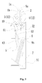
Figure 1 is a side view of a banknote accommodating device according to a first embodiment of the present application; -
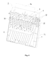
Figure 2 is a perspective schematic view of the banknote accommodating device inFigure 1 , which omits a box body and mainly shows the form and mounting position of an elastic element; -
Figure 3 is a side view of a banknote accommodating device according to a second embodiment of the present application; -
Figure 4 is a perspective view of the banknote accommodating device inFigure 3 , which omits a box body and mainly shows the form and mounting position of an elastic element; -
Figure 5 is a side view of a banknote accommodating device according to a third embodiment of the present application; -
Figure 6 is a perspective view of the banknote accommodating device inFigure 5 , which omits a box body and mainly shows the form and mounting position of an elastic element; and -
Figure 7 is a schematic view showing the internal structure of a cash recycling system which employs the banknote accommodating device according to the present application. - For further illustrating a banknote accommodating device according to the present application, the banknote accommodating device is further described in detail hereinafter in conjunction with illustrations of preferred embodiments of the present application.
- Referring to
Figure 7 , the banknote accommodating device according to this embodiment is employed in a cash recycling system. The cash recycling system includes abanknote inlet module 101, an upper portion upper passage module 102 (102 consists of 102a, 102b, and 102c, and a three-way switching component 111 is mounted on the upper portion upper passage module 102), an upper portionlower passage module 103, abanknote identification module 104, a lowerportion passage module 105, aconveying passage 105, an upper drum-type cashbox 106, a lower drum-type cashbox 107, an audit drum-type cashbox 108, and a banknote accommodatingdevice 109. - When a customer fails to take away the banknotes in the
banknote inlet module 101 within a preset time span in depositing or withdrawing the banknotes, the cash recycling system sends a command to recover the banknotes in thebanknote inlet module 101, and the recovered banknotes are separated and then individually enter into the conveying passage, and enter into thebanknote identification module 104 via the conveying passage, and then enter into the upper portionupper passage module 102b, the three-way switching component 111, the upper portionupper passage module 102c, the upper portionlower passage module 103, and the lowerportion passage module 105 in the listed sequence. A switching member 1 in the lowerportion passage module 105 rotates by a certain angle counterclockwise under the action of a rotational electromagnet, to be in astate 1b (referring toFigure 1 ), and the passage leading to thebanknote accommodating device 109 is opened. - Referring to
Figures 1 and2 , thebanknote accommodating device 109 according to a preferred embodiment of the present application includes abox body 5, abox door 7 and a banknote inlet; the switching member 1 (including twostates 1a and 1b), abox cover 2 and a pair ofpressing roller components box cover 2, and the pair ofpressing roller components pressing roller components banknote 9a into thebox body 5 of the banknote accommodatingdevice 109 in the state that the banknote inlet is open. Thepressing roller components spur gear 12. Amovable guide plate 6 is provided in thebox body 5, and is arranged below thebanknote inlet 2 through a rotatingshaft 61. The rotatingshaft 6 is fixedly mounted to a side wall of thebox body 5, and aguide surface 62 of themovable guide plate 6 faces thebanknote inlet 2, and an included angle formed between theguide surface 62 and a vertical direction ranges from 0 degree to 20 degrees. An elastic element is provided on aback surface 63 of theguide surface 62. The elastic element in this embodiment is aspring 8, and thespring 8 applies a thrust on themovable guide plate 6 to allow themovable guide plate 6 to rotate counterclockwise. Thebox door 7 is provided with aguide rib 71 which forms an included angle ranging from 0 degree to 30 degrees with respect to the vertical direction. Astacking surface 51 is provided at the bottom of thebox body 5, and forms an included angle ranging from 0 degree to 45 degrees with respect to a horizontal direction. A space for stacking banknotes vertically is formed between theguide surface 62 of themovable guide plate 6, theguide rib 71 of thebox door 7 and thestacking surface 51 at the bottom of thebox body 5. The state of the banknotes being stacked vertically in this space is indicated as 9b. - Preferably, a
guide surface 52 is further provided in an upper portion at a left side of thebox body 5, an included angle formed between theguide surface 52 and the vertical direction ranges from 0 degree to 20 degrees, and is configured to guide thebanknote 9a to move from the banknote inlet to theguide surface 62 of themovable guide plate 6. Thebanknote 9a enters along the passage formed by the right side surface of theswitching member 1b and the left side surface of thebox cover 2, and is conveyed into thebox body 5 by thepressing roller component 3 and thepressing roller component 4, and then moves onto the guide surface 62 (a rightward inclined surface in the drawings) of themovable guide plate 6 along theguide surface 52 in the upper portion at the left side of thebox body 5, and then the banknote continues to slide downwards to theguide rib 71 of thebox door 7. Under the combined effects of themovable guide plate 6, thebox door 7, thecompression spring 8 and the self-gravity of the banknote, a front end of the banknote rests on the stackinginclined surface 51 at the bottom of thebox body 5, and the entire sheet of banknote is stacked well against the surface of theguide rib 71 of thebox door 7. With continuously entering of the received banknotes, the banknotes are stacked in thestate 9b. When the banknotes are stacked to a certain thickness, the banknotes entered later will press themovable guide plate 6, to make themovable guide plate 6 to rotate clockwise about its center of rotation (the rotating shaft 61) in a direction as indicated by an arrow inFigure 1 by a certain small angle, to make room for the banknotes entered later. Meanwhile, since thecompression spring 8 is compressed, it generates a certain reaction force to push theguide plate 6 to allow theguide plate 6 to have a trend of rotating counterclockwise, to press the stacked banknotes tightly, thereby accommodating more banknotes. - As shown in
Figures 3 and4 , a second embodiment is further provided according to the present application. Unlike the banknote accommodating device according to the first embodiment, in the banknote accommodating device according to this embodiment, atorsion spring 10 is adopted to replace thecompression spring 8, and thetorsion spring 10 provides a reaction force to push theguide plate 6 to allow theguide plate 6 to have a trend of rotating counterclockwise, to press the stacked banknotes tightly. As shown inFigure 4 , the number of thetorsion springs 10 is two, and the twotorsion springs 10 are sleeved symmetrically on two ends of therotating shaft 61 of themovable guide plate 6, and a torque arm of eachtorsion spring 10 extends towards a back side of themovable guide plate 6 to press against the side wall of thebox body 5, thereby providing a reaction force to the movable guide plate. - As shown in
Figures 5 and6 , a third embodiment is further provided according to the present application. Unlike the banknote accommodating device according to the first embodiment, in the banknote accommodating device according to this embodiment, aleaf spring 11 is adopted to replace thecompression spring 8, and theleaf spring 11 provides a reaction force to push theguide plate 6 to allow theguide plate 6 to have a trend of rotating counterclockwise, to press the stacked banknotes tightly. As shown inFigure 6 , the number of theleaf springs 11 is two, and the twoleaf springs 11 are fixed on theback surface 63 of themovable guide plate 6 bilaterally symmetrically. - The space for stacking the banknotes vertically is formed between the
guide surface 62 of themovable guide plate 6, theguide ribs 71 of thebox door 7 and thestacking surface 51 at the bottom of thebox body 5, thus the banknotes can be stacked vertically, and the box body of the banknote accommodating device may be designed relatively small, to meet the requirement of minimization of the financial self-service device. Furthermore, with the design of themovable guide plate 6 and the elastic element on its back surface allows the size of the banknote stacking space to be adjustable, and with the increasing of the stacked banknotes, the elastic element provides a thrust to the stacked banknotes, to press the stacked banknotes tightly, to accommodate more banknotes. - The above description is only preferred embodiments of the present application. It should be noted that, the above preferred embodiments should not be deemed as a limitation to the present application, and the scope of the present application is defined by the claims of the present application. For the person skilled in the art, several improvements and modifications may be made to the present application without departing from the spirit and scope of the present application, and these improvements and modifications are also deemed to fall into the scope of the present application.
Claims (3)
- A banknote accommodating device, comprising a box body, a box door, and a banknote inlet, a switching member and a pair of pressing roller components being provided at the banknote inlet, the switching member being configured to selectively rotate to open or close the banknote inlet under the control of a control signal, and the pair of pressing roller components being configured to convey banknote into the banknote accommodating device in a state that the banknote inlet is open, wherein,
a movable guide plate is provided in the box body, and is arranged below the banknote inlet through a rotating shaft, the rotating shaft is fixedly mounted to a side wall of the box body, a guide surface of the movable guide plate faces the banknote inlet, and an included angle formed between the guide surface of the movable guide plate and a vertical direction ranges from 0 degree to 20 degrees, an elastic element is provided on a back surface of the guide surface of the movable guide plate, and the elastic element is configured to provide a thrust to the movable guide plate to allow the movable guide plate to rotate counterclockwise; and
the box door is provided with a guide rib which forms an included angle ranging from 0 degree to 30 degrees with respect to the vertical direction, and a stacking surface is provided at the bottom of the box body and forms an included angle ranging from 0 degree to 45 degrees with respect to a horizontal direction, and a space for stacking banknotes vertically is formed between the guide surface of the movable guide plate, the guide rib of the box door and the stacking surface at the bottom of the box body. - The banknote accommodating device according to claim 1, wherein a guide surface is further provided in an upper portion at a left side of the box body, and an included angle formed between the guide surface of the box body and the vertical direction ranges from 0 degree to 20 degrees, and is configured to guide the banknote to move from the banknote inlet to the guide surface of the movable guide plate.
- The banknote accommodating device according to claim 1 or 2, wherein the elastic element comprises a compression spring, a leaf spring or a torsion spring.
Applications Claiming Priority (2)
| Application Number | Priority Date | Filing Date | Title |
|---|---|---|---|
| CN201310723629.4A CN103700182B (en) | 2013-12-24 | 2013-12-24 | Bank note containing device |
| PCT/CN2014/089397 WO2015096544A1 (en) | 2013-12-24 | 2014-10-24 | Paper currency accommodating device |
Publications (3)
| Publication Number | Publication Date |
|---|---|
| EP3089122A1 true EP3089122A1 (en) | 2016-11-02 |
| EP3089122A4 EP3089122A4 (en) | 2017-03-08 |
| EP3089122B1 EP3089122B1 (en) | 2018-09-05 |
Family
ID=50361698
Family Applications (1)
| Application Number | Title | Priority Date | Filing Date |
|---|---|---|---|
| EP14874076.4A Not-in-force EP3089122B1 (en) | 2013-12-24 | 2014-10-24 | Paper currency accommodating device |
Country Status (7)
| Country | Link |
|---|---|
| US (1) | US9542789B2 (en) |
| EP (1) | EP3089122B1 (en) |
| CN (1) | CN103700182B (en) |
| AU (1) | AU2014373179B2 (en) |
| CL (1) | CL2016000789A1 (en) |
| WO (1) | WO2015096544A1 (en) |
| ZA (1) | ZA201601888B (en) |
Families Citing this family (9)
| Publication number | Priority date | Publication date | Assignee | Title |
|---|---|---|---|---|
| CN103700182B (en) * | 2013-12-24 | 2016-01-20 | 广州广电运通金融电子股份有限公司 | Bank note containing device |
| CN106384429B (en) * | 2016-11-11 | 2022-09-30 | 浙江维融电子科技股份有限公司 | Sorting machine |
| CN106408755B (en) * | 2016-11-11 | 2022-09-30 | 浙江维融电子科技股份有限公司 | Paper money pressing structure |
| CN107654513B (en) * | 2017-08-04 | 2023-10-20 | 深圳怡化电脑股份有限公司 | Wheel train positioning mechanism and self-service financial equipment |
| CN107381186B (en) * | 2017-08-07 | 2019-05-10 | 浪潮金融信息技术有限公司 | A kind of recycling bins and its recovery method for storing paper |
| CN109461249B (en) * | 2018-11-23 | 2024-08-06 | 恒银金融科技股份有限公司 | Paper currency stacks finishing device |
| CN110232765A (en) * | 2019-07-10 | 2019-09-13 | 恒银金融科技股份有限公司 | A kind of paper money guide plate and circular bank note box |
| JP7341088B2 (en) * | 2020-03-16 | 2023-09-08 | シャープ株式会社 | printing device |
| CN118025689B (en) * | 2024-02-05 | 2026-02-03 | 广电运通集团股份有限公司 | Self-service equipment for recycling bin and passbook |
Family Cites Families (18)
| Publication number | Priority date | Publication date | Assignee | Title |
|---|---|---|---|---|
| DE4039813C2 (en) * | 1990-12-13 | 1997-03-13 | Kodak Ag | Guide device for the stacked storage of paper sheets |
| JP3023635B2 (en) * | 1993-03-24 | 2000-03-21 | 三田工業株式会社 | Document feeder |
| JP2932338B2 (en) * | 1993-11-05 | 1999-08-09 | 株式会社日本コンラックス | Banknote handling equipment |
| US5419545A (en) * | 1994-03-10 | 1995-05-30 | Unisys Corporation | High speed document stacking assembly |
| US5388818A (en) * | 1994-03-31 | 1995-02-14 | Minnesota Mining And Manufacturing Company | Near vertical media receive magazine |
| US5829673A (en) * | 1996-04-04 | 1998-11-03 | Coin Acceptors, Inc. | Modular cash box |
| US6158565A (en) * | 1997-08-28 | 2000-12-12 | Kabushiki Kaisha Nippon Conlux | Bill processor |
| US5924808A (en) * | 1998-06-29 | 1999-07-20 | Sides, Ii; William R. | Paper catching tray for electronic printers and other devices |
| JP3058150B2 (en) * | 1998-08-28 | 2000-07-04 | 株式会社日立製作所 | Paper handling equipment |
| JP3779076B2 (en) * | 1998-10-06 | 2006-05-24 | 株式会社日本コンラックス | Banknote handling equipment |
| JP4325886B2 (en) * | 1998-12-08 | 2009-09-02 | 日立オムロンターミナルソリューションズ株式会社 | Banknote deposit and withdrawal machine |
| CN1265329C (en) * | 2000-02-18 | 2006-07-19 | 富士电机株式会社 | Paper currency processing device |
| JP4408373B2 (en) * | 2004-01-23 | 2010-02-03 | 日立オムロンターミナルソリューションズ株式会社 | Banknote deposit and withdrawal device |
| FR2887668B1 (en) * | 2005-06-27 | 2007-10-12 | Parkeon | MACHINE FOR DISTRIBUTING PRODUCTS AND / OR SERVICES AGAINST PAYMENT BY TICKETS |
| ITTO20060093A1 (en) | 2006-02-10 | 2007-08-11 | Cts Cashpro Spa | EQUIPMENT FOR STORAGE BANKNOTES AND / OR CARDS AND THE LIKE |
| JP2008250517A (en) | 2007-03-29 | 2008-10-16 | Sanden Corp | Paper money discriminating device |
| JP5342530B2 (en) * | 2010-09-29 | 2013-11-13 | 日立オムロンターミナルソリューションズ株式会社 | Automatic cash transaction equipment |
| CN103700182B (en) * | 2013-12-24 | 2016-01-20 | 广州广电运通金融电子股份有限公司 | Bank note containing device |
-
2013
- 2013-12-24 CN CN201310723629.4A patent/CN103700182B/en active Active
-
2014
- 2014-10-24 AU AU2014373179A patent/AU2014373179B2/en not_active Ceased
- 2014-10-24 EP EP14874076.4A patent/EP3089122B1/en not_active Not-in-force
- 2014-10-24 WO PCT/CN2014/089397 patent/WO2015096544A1/en not_active Ceased
- 2014-10-24 US US15/021,927 patent/US9542789B2/en not_active Expired - Fee Related
-
2016
- 2016-03-17 ZA ZA2016/01888A patent/ZA201601888B/en unknown
- 2016-04-05 CL CL2016000789A patent/CL2016000789A1/en unknown
Also Published As
| Publication number | Publication date |
|---|---|
| WO2015096544A1 (en) | 2015-07-02 |
| US9542789B2 (en) | 2017-01-10 |
| ZA201601888B (en) | 2017-06-28 |
| EP3089122B1 (en) | 2018-09-05 |
| CL2016000789A1 (en) | 2016-09-16 |
| AU2014373179A1 (en) | 2016-04-14 |
| EP3089122A4 (en) | 2017-03-08 |
| AU2014373179B2 (en) | 2016-08-11 |
| CN103700182B (en) | 2016-01-20 |
| US20160225217A1 (en) | 2016-08-04 |
| CN103700182A (en) | 2014-04-02 |
Similar Documents
| Publication | Publication Date | Title |
|---|---|---|
| AU2014373179B2 (en) | Paper currency accommodating device | |
| US9070241B2 (en) | Bill storage box and bill handling device | |
| RU2652976C1 (en) | Rotating device for the paper money transfer | |
| EP2980762B1 (en) | Banknote processing device and circulating cash box mechanism thereof | |
| EP1760020A2 (en) | Paper stacking apparatus | |
| US10074229B2 (en) | Medium storage box and financial device | |
| CN102887376A (en) | Paper type medium separating device | |
| US9142076B2 (en) | Media case and banking machine | |
| CN102163346B (en) | Paper processing device | |
| CN107301722B (en) | Paper money conveying channel device capable of reversing and handling abnormal paper money | |
| JP5157078B2 (en) | Paper sheet processing equipment | |
| JP6532662B2 (en) | Sheet feeding mechanism and sheet processing apparatus | |
| JP5262200B2 (en) | Paper sheet handling equipment | |
| JP6147975B2 (en) | Page turning mechanism | |
| JP6417927B2 (en) | Media processing device | |
| JP3710531B2 (en) | Cash collection equipment | |
| US10167149B2 (en) | Banknote separation apparatus and method for banknote bundle receiving machine | |
| JP2017126171A (en) | Medium processor and automatic transaction device | |
| KR101199145B1 (en) | Apparatus for locking the front panel of ATM | |
| KR101295512B1 (en) | Apparatus to store paper and automatic teller machine having the same | |
| JP6812000B2 (en) | Paper leaf handling device and paper leaf transport method | |
| HK1238400A1 (en) | Rotary paper money conveying device | |
| KR20130073135A (en) | Apparatus to store paper and automatic teller machine having the same | |
| JP2011138459A (en) | Paper sheet holding mechanism and paper sheet handling device | |
| HK1238400B (en) | Rotary paper money conveying device |
Legal Events
| Date | Code | Title | Description |
|---|---|---|---|
| PUAI | Public reference made under article 153(3) epc to a published international application that has entered the european phase |
Free format text: ORIGINAL CODE: 0009012 |
|
| 17P | Request for examination filed |
Effective date: 20160310 |
|
| AK | Designated contracting states |
Kind code of ref document: A1 Designated state(s): AL AT BE BG CH CY CZ DE DK EE ES FI FR GB GR HR HU IE IS IT LI LT LU LV MC MK MT NL NO PL PT RO RS SE SI SK SM TR |
|
| AX | Request for extension of the european patent |
Extension state: BA ME |
|
| REG | Reference to a national code |
Ref country code: DE Ref legal event code: R079 Ref document number: 602014032068 Country of ref document: DE Free format text: PREVIOUS MAIN CLASS: G07D0011000000 Ipc: B65H0031020000 |
|
| A4 | Supplementary search report drawn up and despatched |
Effective date: 20170202 |
|
| RIC1 | Information provided on ipc code assigned before grant |
Ipc: B65H 31/02 20060101AFI20170127BHEP Ipc: G07D 11/00 20060101ALI20170127BHEP Ipc: B65H 31/26 20060101ALI20170127BHEP Ipc: G07F 19/00 20060101ALI20170127BHEP |
|
| DAX | Request for extension of the european patent (deleted) | ||
| STAA | Information on the status of an ep patent application or granted ep patent |
Free format text: STATUS: EXAMINATION IS IN PROGRESS |
|
| 17Q | First examination report despatched |
Effective date: 20170720 |
|
| GRAP | Despatch of communication of intention to grant a patent |
Free format text: ORIGINAL CODE: EPIDOSNIGR1 |
|
| STAA | Information on the status of an ep patent application or granted ep patent |
Free format text: STATUS: GRANT OF PATENT IS INTENDED |
|
| INTG | Intention to grant announced |
Effective date: 20180426 |
|
| GRAS | Grant fee paid |
Free format text: ORIGINAL CODE: EPIDOSNIGR3 |
|
| GRAA | (expected) grant |
Free format text: ORIGINAL CODE: 0009210 |
|
| STAA | Information on the status of an ep patent application or granted ep patent |
Free format text: STATUS: THE PATENT HAS BEEN GRANTED |
|
| AK | Designated contracting states |
Kind code of ref document: B1 Designated state(s): AL AT BE BG CH CY CZ DE DK EE ES FI FR GB GR HR HU IE IS IT LI LT LU LV MC MK MT NL NO PL PT RO RS SE SI SK SM TR |
|
| REG | Reference to a national code |
Ref country code: GB Ref legal event code: FG4D |
|
| REG | Reference to a national code |
Ref country code: CH Ref legal event code: EP |
|
| REG | Reference to a national code |
Ref country code: AT Ref legal event code: REF Ref document number: 1037545 Country of ref document: AT Kind code of ref document: T Effective date: 20180915 |
|
| REG | Reference to a national code |
Ref country code: IE Ref legal event code: FG4D |
|
| REG | Reference to a national code |
Ref country code: DE Ref legal event code: R096 Ref document number: 602014032068 Country of ref document: DE |
|
| REG | Reference to a national code |
Ref country code: FR Ref legal event code: PLFP Year of fee payment: 5 |
|
| REG | Reference to a national code |
Ref country code: NL Ref legal event code: MP Effective date: 20180905 |
|
| REG | Reference to a national code |
Ref country code: LT Ref legal event code: MG4D |
|
| PG25 | Lapsed in a contracting state [announced via postgrant information from national office to epo] |
Ref country code: GR Free format text: LAPSE BECAUSE OF FAILURE TO SUBMIT A TRANSLATION OF THE DESCRIPTION OR TO PAY THE FEE WITHIN THE PRESCRIBED TIME-LIMIT Effective date: 20181206 Ref country code: NO Free format text: LAPSE BECAUSE OF FAILURE TO SUBMIT A TRANSLATION OF THE DESCRIPTION OR TO PAY THE FEE WITHIN THE PRESCRIBED TIME-LIMIT Effective date: 20181205 Ref country code: BG Free format text: LAPSE BECAUSE OF FAILURE TO SUBMIT A TRANSLATION OF THE DESCRIPTION OR TO PAY THE FEE WITHIN THE PRESCRIBED TIME-LIMIT Effective date: 20181205 Ref country code: SE Free format text: LAPSE BECAUSE OF FAILURE TO SUBMIT A TRANSLATION OF THE DESCRIPTION OR TO PAY THE FEE WITHIN THE PRESCRIBED TIME-LIMIT Effective date: 20180905 Ref country code: LT Free format text: LAPSE BECAUSE OF FAILURE TO SUBMIT A TRANSLATION OF THE DESCRIPTION OR TO PAY THE FEE WITHIN THE PRESCRIBED TIME-LIMIT Effective date: 20180905 Ref country code: FI Free format text: LAPSE BECAUSE OF FAILURE TO SUBMIT A TRANSLATION OF THE DESCRIPTION OR TO PAY THE FEE WITHIN THE PRESCRIBED TIME-LIMIT Effective date: 20180905 Ref country code: RS Free format text: LAPSE BECAUSE OF FAILURE TO SUBMIT A TRANSLATION OF THE DESCRIPTION OR TO PAY THE FEE WITHIN THE PRESCRIBED TIME-LIMIT Effective date: 20180905 |
|
| PG25 | Lapsed in a contracting state [announced via postgrant information from national office to epo] |
Ref country code: AL Free format text: LAPSE BECAUSE OF FAILURE TO SUBMIT A TRANSLATION OF THE DESCRIPTION OR TO PAY THE FEE WITHIN THE PRESCRIBED TIME-LIMIT Effective date: 20180905 Ref country code: LV Free format text: LAPSE BECAUSE OF FAILURE TO SUBMIT A TRANSLATION OF THE DESCRIPTION OR TO PAY THE FEE WITHIN THE PRESCRIBED TIME-LIMIT Effective date: 20180905 Ref country code: HR Free format text: LAPSE BECAUSE OF FAILURE TO SUBMIT A TRANSLATION OF THE DESCRIPTION OR TO PAY THE FEE WITHIN THE PRESCRIBED TIME-LIMIT Effective date: 20180905 |
|
| PG25 | Lapsed in a contracting state [announced via postgrant information from national office to epo] |
Ref country code: PL Free format text: LAPSE BECAUSE OF FAILURE TO SUBMIT A TRANSLATION OF THE DESCRIPTION OR TO PAY THE FEE WITHIN THE PRESCRIBED TIME-LIMIT Effective date: 20180905 Ref country code: EE Free format text: LAPSE BECAUSE OF FAILURE TO SUBMIT A TRANSLATION OF THE DESCRIPTION OR TO PAY THE FEE WITHIN THE PRESCRIBED TIME-LIMIT Effective date: 20180905 Ref country code: RO Free format text: LAPSE BECAUSE OF FAILURE TO SUBMIT A TRANSLATION OF THE DESCRIPTION OR TO PAY THE FEE WITHIN THE PRESCRIBED TIME-LIMIT Effective date: 20180905 Ref country code: CZ Free format text: LAPSE BECAUSE OF FAILURE TO SUBMIT A TRANSLATION OF THE DESCRIPTION OR TO PAY THE FEE WITHIN THE PRESCRIBED TIME-LIMIT Effective date: 20180905 Ref country code: NL Free format text: LAPSE BECAUSE OF FAILURE TO SUBMIT A TRANSLATION OF THE DESCRIPTION OR TO PAY THE FEE WITHIN THE PRESCRIBED TIME-LIMIT Effective date: 20180905 Ref country code: ES Free format text: LAPSE BECAUSE OF FAILURE TO SUBMIT A TRANSLATION OF THE DESCRIPTION OR TO PAY THE FEE WITHIN THE PRESCRIBED TIME-LIMIT Effective date: 20180905 Ref country code: IS Free format text: LAPSE BECAUSE OF FAILURE TO SUBMIT A TRANSLATION OF THE DESCRIPTION OR TO PAY THE FEE WITHIN THE PRESCRIBED TIME-LIMIT Effective date: 20190105 |
|
| PG25 | Lapsed in a contracting state [announced via postgrant information from national office to epo] |
Ref country code: SK Free format text: LAPSE BECAUSE OF FAILURE TO SUBMIT A TRANSLATION OF THE DESCRIPTION OR TO PAY THE FEE WITHIN THE PRESCRIBED TIME-LIMIT Effective date: 20180905 Ref country code: PT Free format text: LAPSE BECAUSE OF FAILURE TO SUBMIT A TRANSLATION OF THE DESCRIPTION OR TO PAY THE FEE WITHIN THE PRESCRIBED TIME-LIMIT Effective date: 20190105 Ref country code: SM Free format text: LAPSE BECAUSE OF FAILURE TO SUBMIT A TRANSLATION OF THE DESCRIPTION OR TO PAY THE FEE WITHIN THE PRESCRIBED TIME-LIMIT Effective date: 20180905 |
|
| REG | Reference to a national code |
Ref country code: CH Ref legal event code: PL |
|
| REG | Reference to a national code |
Ref country code: DE Ref legal event code: R097 Ref document number: 602014032068 Country of ref document: DE |
|
| REG | Reference to a national code |
Ref country code: BE Ref legal event code: MM Effective date: 20181031 |
|
| PG25 | Lapsed in a contracting state [announced via postgrant information from national office to epo] |
Ref country code: LU Free format text: LAPSE BECAUSE OF NON-PAYMENT OF DUE FEES Effective date: 20181024 |
|
| PLBE | No opposition filed within time limit |
Free format text: ORIGINAL CODE: 0009261 |
|
| STAA | Information on the status of an ep patent application or granted ep patent |
Free format text: STATUS: NO OPPOSITION FILED WITHIN TIME LIMIT |
|
| REG | Reference to a national code |
Ref country code: IE Ref legal event code: MM4A |
|
| PG25 | Lapsed in a contracting state [announced via postgrant information from national office to epo] |
Ref country code: DK Free format text: LAPSE BECAUSE OF FAILURE TO SUBMIT A TRANSLATION OF THE DESCRIPTION OR TO PAY THE FEE WITHIN THE PRESCRIBED TIME-LIMIT Effective date: 20180905 Ref country code: MC Free format text: LAPSE BECAUSE OF FAILURE TO SUBMIT A TRANSLATION OF THE DESCRIPTION OR TO PAY THE FEE WITHIN THE PRESCRIBED TIME-LIMIT Effective date: 20180905 |
|
| 26N | No opposition filed |
Effective date: 20190606 |
|
| PG25 | Lapsed in a contracting state [announced via postgrant information from national office to epo] |
Ref country code: SI Free format text: LAPSE BECAUSE OF FAILURE TO SUBMIT A TRANSLATION OF THE DESCRIPTION OR TO PAY THE FEE WITHIN THE PRESCRIBED TIME-LIMIT Effective date: 20180905 Ref country code: LI Free format text: LAPSE BECAUSE OF NON-PAYMENT OF DUE FEES Effective date: 20181031 Ref country code: CH Free format text: LAPSE BECAUSE OF NON-PAYMENT OF DUE FEES Effective date: 20181031 Ref country code: BE Free format text: LAPSE BECAUSE OF NON-PAYMENT OF DUE FEES Effective date: 20181031 |
|
| PG25 | Lapsed in a contracting state [announced via postgrant information from national office to epo] |
Ref country code: IE Free format text: LAPSE BECAUSE OF NON-PAYMENT OF DUE FEES Effective date: 20181024 |
|
| PGFP | Annual fee paid to national office [announced via postgrant information from national office to epo] |
Ref country code: TR Payment date: 20190917 Year of fee payment: 6 |
|
| PG25 | Lapsed in a contracting state [announced via postgrant information from national office to epo] |
Ref country code: MT Free format text: LAPSE BECAUSE OF NON-PAYMENT OF DUE FEES Effective date: 20181024 |
|
| PGFP | Annual fee paid to national office [announced via postgrant information from national office to epo] |
Ref country code: DE Payment date: 20191028 Year of fee payment: 6 |
|
| PGFP | Annual fee paid to national office [announced via postgrant information from national office to epo] |
Ref country code: IT Payment date: 20190926 Year of fee payment: 6 Ref country code: FR Payment date: 20191022 Year of fee payment: 6 |
|
| PGFP | Annual fee paid to national office [announced via postgrant information from national office to epo] |
Ref country code: AT Payment date: 20191031 Year of fee payment: 6 |
|
| PGFP | Annual fee paid to national office [announced via postgrant information from national office to epo] |
Ref country code: GB Payment date: 20191023 Year of fee payment: 6 |
|
| REG | Reference to a national code |
Ref country code: AT Ref legal event code: UEP Ref document number: 1037545 Country of ref document: AT Kind code of ref document: T Effective date: 20180905 |
|
| PG25 | Lapsed in a contracting state [announced via postgrant information from national office to epo] |
Ref country code: CY Free format text: LAPSE BECAUSE OF FAILURE TO SUBMIT A TRANSLATION OF THE DESCRIPTION OR TO PAY THE FEE WITHIN THE PRESCRIBED TIME-LIMIT Effective date: 20180905 Ref country code: HU Free format text: LAPSE BECAUSE OF FAILURE TO SUBMIT A TRANSLATION OF THE DESCRIPTION OR TO PAY THE FEE WITHIN THE PRESCRIBED TIME-LIMIT; INVALID AB INITIO Effective date: 20141024 Ref country code: MK Free format text: LAPSE BECAUSE OF NON-PAYMENT OF DUE FEES Effective date: 20180905 |
|
| REG | Reference to a national code |
Ref country code: DE Ref legal event code: R119 Ref document number: 602014032068 Country of ref document: DE |
|
| REG | Reference to a national code |
Ref country code: AT Ref legal event code: MM01 Ref document number: 1037545 Country of ref document: AT Kind code of ref document: T Effective date: 20201024 |
|
| GBPC | Gb: european patent ceased through non-payment of renewal fee |
Effective date: 20201024 |
|
| PG25 | Lapsed in a contracting state [announced via postgrant information from national office to epo] |
Ref country code: DE Free format text: LAPSE BECAUSE OF NON-PAYMENT OF DUE FEES Effective date: 20210501 Ref country code: FR Free format text: LAPSE BECAUSE OF NON-PAYMENT OF DUE FEES Effective date: 20201031 |
|
| PG25 | Lapsed in a contracting state [announced via postgrant information from national office to epo] |
Ref country code: GB Free format text: LAPSE BECAUSE OF NON-PAYMENT OF DUE FEES Effective date: 20201024 Ref country code: AT Free format text: LAPSE BECAUSE OF NON-PAYMENT OF DUE FEES Effective date: 20201024 |
|
| PG25 | Lapsed in a contracting state [announced via postgrant information from national office to epo] |
Ref country code: IT Free format text: LAPSE BECAUSE OF NON-PAYMENT OF DUE FEES Effective date: 20201024 |
|
| PG25 | Lapsed in a contracting state [announced via postgrant information from national office to epo] |
Ref country code: TR Free format text: LAPSE BECAUSE OF NON-PAYMENT OF DUE FEES Effective date: 20201024 |