EP3088930A1 - Optical fiber cable - Google Patents
Optical fiber cable Download PDFInfo
- Publication number
- EP3088930A1 EP3088930A1 EP16162554.6A EP16162554A EP3088930A1 EP 3088930 A1 EP3088930 A1 EP 3088930A1 EP 16162554 A EP16162554 A EP 16162554A EP 3088930 A1 EP3088930 A1 EP 3088930A1
- Authority
- EP
- European Patent Office
- Prior art keywords
- optical fiber
- core
- range
- refractive index
- fiber cable
- Prior art date
- Legal status (The legal status is an assumption and is not a legal conclusion. Google has not performed a legal analysis and makes no representation as to the accuracy of the status listed.)
- Granted
Links
Images




Classifications
-
- G—PHYSICS
- G02—OPTICS
- G02B—OPTICAL ELEMENTS, SYSTEMS OR APPARATUS
- G02B6/00—Light guides; Structural details of arrangements comprising light guides and other optical elements, e.g. couplings
- G02B6/44—Mechanical structures for providing tensile strength and external protection for fibres, e.g. optical transmission cables
- G02B6/4401—Optical cables
- G02B6/4407—Optical cables with internal fluted support member
- G02B6/4409—Optical cables with internal fluted support member for ribbons
-
- G—PHYSICS
- G02—OPTICS
- G02B—OPTICAL ELEMENTS, SYSTEMS OR APPARATUS
- G02B6/00—Light guides; Structural details of arrangements comprising light guides and other optical elements, e.g. couplings
- G02B6/02—Optical fibres with cladding with or without a coating
- G02B6/02004—Optical fibres with cladding with or without a coating characterised by the core effective area or mode field radius
- G02B6/02009—Large effective area or mode field radius, e.g. to reduce nonlinear effects in single mode fibres
- G02B6/02014—Effective area greater than 60 square microns in the C band, i.e. 1530-1565 nm
- G02B6/02019—Effective area greater than 90 square microns in the C band, i.e. 1530-1565 nm
-
- G—PHYSICS
- G02—OPTICS
- G02B—OPTICAL ELEMENTS, SYSTEMS OR APPARATUS
- G02B6/00—Light guides; Structural details of arrangements comprising light guides and other optical elements, e.g. couplings
- G02B6/02—Optical fibres with cladding with or without a coating
- G02B6/02042—Multicore optical fibres
-
- G—PHYSICS
- G02—OPTICS
- G02B—OPTICAL ELEMENTS, SYSTEMS OR APPARATUS
- G02B6/00—Light guides; Structural details of arrangements comprising light guides and other optical elements, e.g. couplings
- G02B6/02—Optical fibres with cladding with or without a coating
- G02B6/02214—Optical fibres with cladding with or without a coating tailored to obtain the desired dispersion, e.g. dispersion shifted, dispersion flattened
- G02B6/02219—Characterised by the wavelength dispersion properties in the silica low loss window around 1550 nm, i.e. S, C, L and U bands from 1460-1675 nm
- G02B6/02266—Positive dispersion fibres at 1550 nm
-
- G—PHYSICS
- G02—OPTICS
- G02B—OPTICAL ELEMENTS, SYSTEMS OR APPARATUS
- G02B6/00—Light guides; Structural details of arrangements comprising light guides and other optical elements, e.g. couplings
- G02B6/02—Optical fibres with cladding with or without a coating
- G02B6/036—Optical fibres with cladding with or without a coating core or cladding comprising multiple layers
- G02B6/03616—Optical fibres characterised both by the number of different refractive index layers around the central core segment, i.e. around the innermost high index core layer, and their relative refractive index difference
- G02B6/03638—Optical fibres characterised both by the number of different refractive index layers around the central core segment, i.e. around the innermost high index core layer, and their relative refractive index difference having 3 layers only
- G02B6/03655—Optical fibres characterised both by the number of different refractive index layers around the central core segment, i.e. around the innermost high index core layer, and their relative refractive index difference having 3 layers only arranged - + +
-
- G—PHYSICS
- G02—OPTICS
- G02B—OPTICAL ELEMENTS, SYSTEMS OR APPARATUS
- G02B6/00—Light guides; Structural details of arrangements comprising light guides and other optical elements, e.g. couplings
- G02B6/44—Mechanical structures for providing tensile strength and external protection for fibres, e.g. optical transmission cables
- G02B6/4401—Optical cables
- G02B6/4407—Optical cables with internal fluted support member
- G02B6/4408—Groove structures in support members to decrease or harmonise transmission losses in ribbon cables
-
- G—PHYSICS
- G02—OPTICS
- G02B—OPTICAL ELEMENTS, SYSTEMS OR APPARATUS
- G02B6/00—Light guides; Structural details of arrangements comprising light guides and other optical elements, e.g. couplings
- G02B6/02—Optical fibres with cladding with or without a coating
- G02B6/028—Optical fibres with cladding with or without a coating with core or cladding having graded refractive index
- G02B6/0281—Graded index region forming part of the central core segment, e.g. alpha profile, triangular, trapezoidal core
-
- G—PHYSICS
- G02—OPTICS
- G02B—OPTICAL ELEMENTS, SYSTEMS OR APPARATUS
- G02B6/00—Light guides; Structural details of arrangements comprising light guides and other optical elements, e.g. couplings
- G02B6/02—Optical fibres with cladding with or without a coating
- G02B6/036—Optical fibres with cladding with or without a coating core or cladding comprising multiple layers
- G02B6/03616—Optical fibres characterised both by the number of different refractive index layers around the central core segment, i.e. around the innermost high index core layer, and their relative refractive index difference
- G02B6/03622—Optical fibres characterised both by the number of different refractive index layers around the central core segment, i.e. around the innermost high index core layer, and their relative refractive index difference having 2 layers only
- G02B6/03627—Optical fibres characterised both by the number of different refractive index layers around the central core segment, i.e. around the innermost high index core layer, and their relative refractive index difference having 2 layers only arranged - +
Definitions
- the present invention relates to an optical fiber cable.
- an optical communication system using an optical fiber arranged in a transmission line it is desirable to transmit information in high volume.
- an optical wavelength band used for an optical communication system is limited to C band: 1530 to 1565 nm and L band: 1565 to 1610 nm
- SE spectral efficiency
- an optical fiber cable which includes and integrally covers a plurality of optical fibers is arranged in, for example, a conduit line placed underground. Since the space in the conduit line is limited, it is desirable to transmit information in higher volume with an optical fiber cable having a smaller sectional area.
- Spectral efficiency per unit sectional area of an optical fiber cable is expressed as a spatial spectral efficiency (SSE) [b/s/Hz/mm 2 ] .
- Japanese Unexamined Patent Application Publication No. 2014-067020 discloses an optical fiber that improves an optical signal to noise ratio (OSNR) while taking account of high-density packing in an optical cable.
- International Publication No. 2013/129234 discloses an optical fiber that increases SE per unit sectional area of an optical fiber. With the optical fiber described in Japanese Unexamined Patent Application Publication No. 2014-067020 , an effective area Aeff is limited to 100 ⁇ m 2 or smaller. Also, SSE of the optical fiber cable is not considered.
- the optical fiber described in International Publication No. 2013/129234 is a multi-core optical fiber, but is not a single core fiber. Also, an optical fiber cable is not considered.
- An object of the invention is to provide an optical fiber cable that increases SE per unit sectional area of the optical fiber cable.
- An optical fiber cable has a sectional area of Ac [ ⁇ m 2 ] and including a number N of optical fibers.
- a transmission loss ⁇ dB [dB/km], a mode field diameter (MFD) W [ ⁇ m], an effective area Aeff [ ⁇ m 2 ], an effective length L eff [km], and a wavelength dispersion D [ps/nm/km] of each of the optical fibers at a wavelength of 1550 nm satisfy Eq.
- the transmission loss of the optical fiber at the wavelength of 1550 nm may be 0.18 dB/km or less, and the Aeff of the optical fiber may be in a range from 100 to 125 ⁇ m 2 .
- the mode field diameter (MFD) of the optical fiber at the wavelength of 1550 nm may be in a range from 11.0 to 12.5 ⁇ m.
- the wavelength dispersion of the optical fiber at the wavelength of 1550 nm may be in a range from 19 to 22 ps/nm/km.
- the optical fiber may have a cutoff wavelength in a range from 1400 to 1600 nm.
- the optical fiber included in the optical fiber cable according to the aspect of the invention may include a core and a cladding, a relative refractive index difference n core ⁇ n cladding n core of the core with respect to the cladding may be in a range from 0.30% to 0.35%, and the core may have a diameter in a range from 10 to 13 ⁇ m.
- the optical fiber may include a core, an inner cladding, and an outer cladding
- the outer cladding may have a refractive index that is smaller than a refractive index of the core and larger than a refractive index of the inner cladding
- a relative refractive index difference n outer cladding ⁇ n inner cladding n outer cladding of the outer cladding with respect to the inner cladding may be in a range from 0.05% to 0.10%
- a relative refractive index difference n core ⁇ n inner cladding n core of the core with respect to the inner cladding may be in a range from 0.30% to 0.35%
- the core may have a diameter in a range from 10 to 13 ⁇ m.
- a relative refractive index difference n core ⁇ n pure silica n pure silica of the core with respect to pure silica may be in a range from -0.1 % to +0.1 %.
- the optical fiber cable according to the aspect of the invention may be a ribbon slotted-core cable, and a value obtained by dividing a sectional area of a single slot by a number of the optical fibers housed in the single slot may be in a range from 0.12 to 0.16 mm 2 /core.
- the optical fiber cable according to the aspect of the invention may be a ribbon slotted-core cable, a value obtained by dividing a sectional area of a single slot by a number of the optical fibers housed in the single slot may be in a range from 0.12 to 0.16 mm 2 /core, and the transmission loss of the optical fiber at the wavelength of 1550 nm may be 0.18 dB/km or less, and the Aeff of the optical fiber at the wavelength of 1550 nm may be in a range from 100 to 125 ⁇ m 2 .
- the optical fiber cable that increases SE per unit sectional area of the optical fiber cable can be provided.
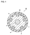
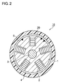
- Figures 1 to 3 are cross-sectional views of optical fiber cables 10 according to an embodiment of the invention.
- a structure of the optical fiber cables 10 is properly selected depending on the arrangement place and environment.
- the number of optical fibers is determined depending on the total required transmission capacity and the space of the conduit.
- Fig. 1 , Fig. 2 , and Fig. 3 show an optical fiber cable including 40 optical fibers, 100 optical fibers, and 300 optical fibers, respectively.
- Fig. 4 is a cross-sectional view showing an example of a slot included in the optical fiber cable 10.
- the optical fiber cable 10 is so-called ribbon slotted-core optical fiber cable.
- the optical fiber cable 10 includes a slotted core 1, a tension member 3, a sheath 4, a water seal tape 5, and a fiber ribbon 20.
- the slotted core 1 is a resin rod made of, for example, a plastic having a substantially cylindrical shape.
- a slot 2 is engraved in the slotted core 1.
- the slot 2 is a groove for housing the fiber ribbon 20.
- a plurality of the slots 2 are provided in the outer peripheral surface of the slotted core 1 along the axial direction of the optical fiber cable 10. Five slots 2 are provided in each case of a cable having 40 optical fibers and 100 optical fibers, and fifteen slots are provided in a case of a cable having 300 optical fibers.
- the width of a bottom portion of the slot 2 is x1, the width of an upper portion of the slot 2 is x2, and the depth of the slot 2 is y. In Fig. 4 , x1 equals to x2; however, x1 does not necessarily equal to x2.
- the tension member 3 is arranged in a center portion of the slotted core 1, and is integrally provided with the slotted core 1.
- the tension member 3 is made of fiber reinforced plastic (FRP).
- FRP fiber reinforced plastic
- FRP is formed by impregnating bound tensile-strength fibers with matrix resin, and the matrix resin is hardened by thermosetting.
- the water seal tape 5 is wound around the outer peripheral surface of the slotted core 1 to cover the slot 2, and functions as a binding tape.
- the water seal tape 5 prevents the fiber ribbon 20 from protruding out from the slot 2.
- the water seal tape 5 is formed of a water absorbing material, and prevents water from running in the longitudinal direction of the optical fiber cable 10.
- the sheath 4 is provided at an outermost peripheral portion of the optical fiber cable 10.
- the sheath 4 is formed of a high-strength plastic.
- the sheath 4 may use a high-strength plastic, such as polyethylene, polyphenylene sulfide, polyether sulfon, polyether etherketone, or liquid crystal polymer.
- the sheath 4 is formed by extruding a high-intensity plastic on the outer periphery of the slotted core 1 covered with the water seal tape 5.
- the fiber ribbon 20 includes a plurality of optical fibers 30 arranged in parallel and integrated.
- the fiber ribbon 20 is formed as a four fiber ribbon having integrated therein four optical fibers 30.
- the fiber ribbons 20 are stacked by, for example, two in a case of a cable having 40 optical fibers, and five in each case of a cable having 100 optical fibers and 300 optical fibers, and are housed in each slot 2.
- a value A slot obtained by dividing the sectional area (x1+x2)xy/2 by the number of fiber N slot in a single slot, that is, A slot (x1+x2) ⁇ y/(2 ⁇ N slot ) is set in a range from 0.12 to 0.16 mm 2 /core.
- SSE and SSE of an optical fiber cable of related art are described next, and then SSE of the optical fiber cable 10 and an optical fiber 30 according to this embodiment are described.
- p equals 2.
- R s denotes a symbol rate
- B ref denotes a reference bandwidth of OSNR, B ref typically being 12.5 GHz (0.1 nm).
- ⁇ denotes a nonlinear coefficient [1/W/km]
- D denotes a chromatic dispersion [ps/nm/km]
- ⁇ denotes a transmission loss [1/km]
- n 2 denotes a nonlinear refractive index [m 2 /W]
- Aeff denotes an effective area [ ⁇ m 2 ] of an optical fiber.
- ⁇ 1.2/W/km
- D 17 ps/nm/km
- ⁇ 0.047/km (0.185 dB/km)
- n 2 2.35 ⁇ 10 -20 m 2 /W
- Aeff 80 ⁇ m 2 .
- L eff denotes an effective length [km]
- L denotes a span length (a repeater interval) [km]
- N s denotes the number of spans
- NF denotes a noise figure of a repeater (Erbium doped fiber amplifier, EDFA)
- h denotes a Planck's constant 6.63 ⁇ 10 -34 [Js]
- v denotes a frequency [THz] of an optical signal
- C denotes the speed of light 3 ⁇ 10 8 [m/s]
- B t denotes a wavelength division multiplexing (WDM) signal band [GHz].
- WDM wavelength division multiplexing
- a sp denotes a splice loss between the optical fiber and the repeaters at both ends of the span, and can be obtained from MFD of the optical fiber and standard SMF. If it is assumed that MFD of standard SMF at the wavelength of 1550 nm is 10.2 ⁇ m, A sp of the optical fiber with MFD being W [ ⁇ m] can be substantially expressed as [20 ⁇ W/(W 2 +104)] 2 .
- a typical ribbon slotted-core optical fiber cable of related art has a cable diameter of about 12 mm in the case where the cable includes 40 fibers, about 17 mm in the case where the cable includes 100 fibers, and about 23 mm in the case where the cable includes 300 fibers. Also, an optical fiber housed in the optical fiber cable of related art uses standard SMF.
- a transmission loss of an optical fiber cable is equivalent to a transmission loss of an optical fiber if a bending loss or a micro-bending loss is not added when the optical fiber is housed in the cable.
- some optical fiber may have a transmission loss which is increased by a bending loss or a micro-bending loss when the optical fiber is housed in the cable.
- a bending loss or a micro-bending loss when an optical fiber is wound around a small-diameter bobbin may be released and a transmission loss may be decreased.
- a difference between a transmission loss after standard SMF is housed in a typical ribbon slotted-core cable of related art and a transmission loss of standard SMF was 0.00 dB/km in average and +0.018 dB/km in maximum.
- SSE when standard SMF is housed in the typical ribbon slotted-core optical fiber cable of related art is 1.5 b/s/Hz/mm 2 in the case where the cable includes 40 fibers, 1.9 b/s/Hz/mm 2 in the case where the cable includes 100 fibers, and 3.2 b/s/Hz/mm 2 in the case where the cable includes 300 fibers.
- the optical fiber cable 10 has a cable diameter of about 11 mm, 13 mm, 17 mm, or 19 mm in the case where the cable includes 40 fibers, 100 fibers, 200 fibers, of 300 fibers respectively.
- the optical fiber cable 10 satisfies Eq. (13): SSE ⁇ 0.008 ⁇ N + 1.7 , where ⁇ dB denotes a transmission loss [dB/km] of the optical fiber 30 as described above.
- SSE can be increased by 30% or more as compared with the ribbon slotted-core optical fiber cable of related art including the same number of standard SMFs. More preferably, Eq. (14) is satisfied: SSE ⁇ 0.009 ⁇ N + 2.0.
- SSE can be increased by 50% or more as compared with the ribbon slotted-core optical fiber cable of related art including the same number of standard SMFs. Further preferably, Eq. (15): SSE ⁇ 0.011 ⁇ N + 2.3 is satisfied. Accordingly, SSE can be increased by 75% or more as compared with the ribbon slotted-core optical fiber cable of related art including the same number of standard SMFs. It is to be noted that the left sides of Eqs. (13), (14), and (15) are the same as the right sides of Eq. (12).
- the optical fiber 30 housed in the optical fiber cable 10 according to this embodiment is preferably a single core fiber for two reasons.
- multi-core fiber In a case of multi-core fiber, it is difficult to splice multi-core fibers of the same type with a low loss.
- misalignment in a range from about 0.2 to about 0.4 ⁇ m may be generated.
- the length of a single optical fiber cable arranged is in a range from about 1 to about 5 km.
- the number of same-type splicing portions is 20 to 100 portions per span.
- the total span loss is largely increased by the splice loss.
- the multi-core fiber is connected to devices at both ends of the span, a device for branching each core is required, and the insertion loss thereof is added. Hence, the total loss is increased.
- the optical fiber 30 preferably has the following features (1) to (5) at the wavelength of 1550 nm.
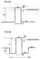
- Figures 6A and 6B are conceptual diagrams showing refractive index profiles of optical fibers 30 according to the embodiment.
- one example of the optical fiber 30 includes a core having a refractive index n1 and a diameter 2a [ ⁇ m], and a cladding having a refractive index n2.
- ⁇ 1 is preferably in a range from 0.30% to 0.35% and 2a is preferably in a range from 10 to 13 ⁇ m. Also, ⁇ 0 is preferably in a range from -0.1% to +0.1%. It is effective not to substantially add a dopant to the core through which a major part of power of an optical signal propagates, in order to decrease the fiber transmission loss.
- another example of the optical fiber 30 includes a core having a refractive index n1 and a diameter 2a [ ⁇ m], an inner cladding having a refractive index n2 and a diameter 2b [ ⁇ m], and an outer cladding having a refractive index n3.
- the optical fiber has a depressed cladding type refractive index profile being n1 > n3 > n2. Since the optical fiber 30 has the depressed cladding type refractive index profile, the bending loss can be suppressed at a relatively low value even when Aeff is increased. Hence, this example of the optical fiber 30 is preferable.
- ⁇ 1 a relative refractive index difference of the core with respect to the refractive index n0 of pure silica ⁇ 0 [%] is 100 ⁇ (n1-n0)/n1
- ⁇ 1 is preferably in a range from 0.30% to 0.35%
- ⁇ 2 preferably in a range from 0.05% to 0.10%
- 2a is preferably in a range from 10 to 13 ⁇ m
- 2b is preferably in a range from 40 to 55 ⁇ m.
- ⁇ 0 is preferably in a range from -0.1 % to +0.1%. It is effective not to substantially add a dopant to the core through which a major part of power
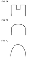
- Figures 7A to 7F are illustrations showing index profiles of cores of optical fibers according to this embodiment,
- the index profile of the core of an optical fiber 30 can be modified in any one of various shapes. In this case, it is assumed that the average value of refractive indices of a core is n1.
- the optical fiber cable 10 houses the plurality of optical fibers 30 and satisfies Eq. (1). Accordingly, SSE of the optical fiber cable 10 can be increased by 30% as compared with the ribbon slotted-core fiber cable of related art housing a standard single-mode fiber (standard SMF) when the numbers of optical fibers are the same. Also, since the transmission loss of the optical fiber 30 at the wavelength of 1550 nm is 0.18 dB/km or less, and Aeff is in the range from 100 to 125 ⁇ m 2 , the transmission loss can be suppressed with an increased SSE value.
- standard SMF standard single-mode fiber
- MFD of the optical fiber at the wavelength of 1550 nm is in the range from 11.0 to 12.5 ⁇ m
- the splice loss between the same-type fibers can be suppressed at a low value even with misalignment, and the splice loss with respect to standard SMF used as the pigtail of the repeater can be suppressed at a low value.
- the dispersion of the optical fiber 30 at the wavelength of 1550 nm is in the range from 19 to 22 ps/nm/km, SSE can be increased.
- the cutoff wavelength of the optical fiber 30 is in the range from 1400 to 1600 nm, by increasing the cutoff wavelength of the optical fiber cable within a range available for single-mode transmission, the bending loss can be suppressed at a low value and the transmission loss of the optical fiber in the cable can be maintained at a low value.
- the optical fiber 30 includes the core and the cladding layer, the relative refractive index difference ⁇ 1 of the core with respect to the cladding is in the range from 0.30% to 0.35%, and the diameter 2a of the core is in the range from 10 to 13 ⁇ m. Accordingly, SSE of the optical fiber cable 10 can be increased.
- the optical fiber 30 includes the core, the inner cladding, and the outer cladding.
- the refractive index n3 of the outer cladding is smaller than the refractive index n1 of the core and is larger than the refractive index n2 of the inner cladding.
- the relative refractive index difference ⁇ 2 of the outer cladding with respect to the inner cladding is in the range from 0.05% to 0.10%
- the relative refractive index difference ⁇ 1 of the core with respect to the inner cladding is in the range from 0.30% to 0.35%
- the diameter 2a of the core is in the range from 10 to 13 ⁇ m. Accordingly, even if Aeff is increased, the bending loss can be suppressed at a relatively low value, and SSE of the optical fiber cable can be increased.
- the relative refractive index difference ⁇ 0 of the core with respect to pure silica is in the range from -0.1 % to +0.1%, and a dopant is not substantially added to the core through which the major part of the power of the optical signal propagates, the transmission loss of the optical fiber 30 can be decreased.
- the optical fiber cable 10 is the ribbon slotted-core cable.
- the value A slot obtained by dividing the sectional area of the single slot 2 by the number of optical fibers N slot housed in the single slot 2 is in the range from 0.12 to 0.16 mm 2 /core. If the sectional area (x1+x2) ⁇ y/2 of the slot 2 is decreased, the sectional area of the cable can be decreased. This is advantageous to increase SSE of the optical fiber cable 10. However, if the sectional area of the slot 2 is excessively decreased, the clearance with respect to the fiber ribbon 20 is decreased. Accordingly, the fiber ribbon 20 contacts the inner wall of the slot 2, and the bending loss and micro-bending loss are generated by the stress of the optical fiber 30.
- the loss is increased more than the loss of the cable of related art, and SSE is decreased.
- the confinement for the propagation light in the core is weakened, and the bending loss and micro-bending loss are likely generated.
- the sectional area of the cable can be decreased while the difference in transmission loss between the optical fiber 30 and the optical fiber cable 10 is suppressed to be equivalent to a case in which standard SMF is housed in the typical ribbon slotted-core cable of related art. Consequently, SSE of the optical fiber cable 10 can be increased.
- the optical fiber cable 10 is the ribbon slotted-core cable
- the value A slot obtained by dividing the sectional area of the single slot 2 by the number of optical fibers N slot housed in the single slot 2 is in the range from 0.12 to 0.16 mm 2 /core
- the transmission loss of the optical fiber 30 at the wavelength of 1550 nm is 0.18 dB/km or lower
- Aeff is in the range from 100 to 125 ⁇ m 2 .
- the sectional area of the cable can be decreased while the difference in transmission loss between the optical fiber 30 and the optical fiber cable 10 is suppressed to be equivalent to the case in which standard SMF is housed in the typical ribbon slotted-core cable of related art. Consequently, SSE of the optical fiber cable 10 can be increased. Also, the transmission loss can be suppressed with an increased SSE value.
- An optical fiber according to Example 1 was an optical fiber having a refractive index profile as shown in Fig. 6A .
- Optical fibers according to Examples 2 to 5 were optical fibers each having a depressed cladding type refractive index profile as shown in Fig. 6B .
- An optical fiber according to the comparative example was standard SMF.
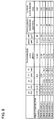
- Figure 8 is a table showing structures of optical fibers and optical characteristics at the wavelength of 1550 nm according to the comparative example and the examples.
- Figure 9 is a table showing SSE when the optical fibers according to the examples were housed in optical fiber cables.
- the difference between the cable transmission loss when the optical fiber according to any one of the examples was housed in the optical fiber cable according to the embodiment of the invention and the transmission loss shown in Fig. 8 was 0.02 dB/km or less even at maximum, which is substantially equivalent to a case in which standard SMF is housed in the typical ribbon slotted-core cable of related art.
- SSE was obtained from Eq.
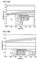
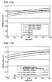
- Figures 10A, 10B , 11A, and 11B are graphs each showing the relationship between Aeff of an optical fiber at the wavelength of 1550 nm and SSE of an optical fiber cable.
- Figures 10A, 10B , 11A, and 11B shows the cases in which the optical fiber cable includes 40 fibers, 100 fibers 200 fibers, and 300 fibers, respectively.
- Each figure shows the relationship between Aeff of the optical fiber at the wavelength of 1550 nm and SSE of the optical fiber cable, for each of cases of fiber transmission losses being 0.180, 0.170, and 0.160 dB/km.
- each figure shows the values of the right sides in Eqs. (13) to (15).
- the difference in transmission loss between the cable and the fiber is 0.02 dB/km or smaller even at maximum, and similarly to the case in which standard SMF is housed in the typical ribbon slotted-core cable of related art, the value obtained by adding 0.02 dB/km to the fiber transmission loss is treated as a substantially standard cable transmission loss.
- Figs. 10A, 10B , 11A, and 11B as long as Aeff is 100 ⁇ m 2 or larger and the fiber transmission loss is 0.180 dB/km or lower, Eq. (13) can be satisfied.
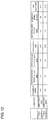
- Figure 12 is a table showing slot sizes and other specifications of optical fiber cables according to examples.
- a slot is set in the range from 0.12 to 0.16 mm 2 /core. Accordingly, even when the optical fiber is housed, the sectional area of the cable can be decreased while the difference in transmission loss between the optical fiber and the optical fiber cable is suppressed to be equivalent to the case in which standard SMF is housed in the typical ribbon slotted-core cable of related art.
Landscapes
- Physics & Mathematics (AREA)
- General Physics & Mathematics (AREA)
- Optics & Photonics (AREA)
- Chemical & Material Sciences (AREA)
- Dispersion Chemistry (AREA)
- Optical Communication System (AREA)
- Optical Fibers, Optical Fiber Cores, And Optical Fiber Bundles (AREA)
Abstract
Description
- The present invention relates to an optical fiber cable.
- With an optical communication system using an optical fiber arranged in a transmission line, it is desirable to transmit information in high volume. In general, since an optical wavelength band used for an optical communication system is limited to C band: 1530 to 1565 nm and L band: 1565 to 1610 nm, to transmit information in high volume, it is desirable that spectral efficiency (SE) [b/s/Hz] expressing a transmission capacity per frequency is high.
- Also, an optical fiber cable which includes and integrally covers a plurality of optical fibers is arranged in, for example, a conduit line placed underground. Since the space in the conduit line is limited, it is desirable to transmit information in higher volume with an optical fiber cable having a smaller sectional area. Spectral efficiency per unit sectional area of an optical fiber cable is expressed as a spatial spectral efficiency (SSE) [b/s/Hz/mm2].
- Japanese Unexamined Patent Application Publication No.
2014-067020 2013/129234 2014-067020 2013/129234 - An object of the invention is to provide an optical fiber cable that increases SE per unit sectional area of the optical fiber cable.
- An optical fiber cable according to an aspect of the invention has a sectional area of Ac [µm2] and including a number N of optical fibers. A transmission loss αdB [dB/km], a mode field diameter (MFD) W [µm], an effective area Aeff [µm2], an effective length Leff [km], and a wavelength dispersion D [ps/nm/km] of each of the optical fibers at a wavelength of 1550 nm satisfy Eq. (1):

- In the optical fiber cable according to the aspect of the invention, the transmission loss of the optical fiber at the wavelength of 1550 nm may be 0.18 dB/km or less, and the Aeff of the optical fiber may be in a range from 100 to 125 µm2. The mode field diameter (MFD) of the optical fiber at the wavelength of 1550 nm may be in a range from 11.0 to 12.5 µm. The wavelength dispersion of the optical fiber at the wavelength of 1550 nm may be in a range from 19 to 22 ps/nm/km. The optical fiber may have a cutoff wavelength in a range from 1400 to 1600 nm.
- The optical fiber included in the optical fiber cable according to the aspect of the invention may include a core and a cladding, a relative refractive index difference


- The optical fiber cable according to the aspect of the invention may be a ribbon slotted-core cable, and a value obtained by dividing a sectional area of a single slot by a number of the optical fibers housed in the single slot may be in a range from 0.12 to 0.16 mm2/core. Alternatively, the optical fiber cable according to the aspect of the invention may be a ribbon slotted-core cable, a value obtained by dividing a sectional area of a single slot by a number of the optical fibers housed in the single slot may be in a range from 0.12 to 0.16 mm2/core, and the transmission loss of the optical fiber at the wavelength of 1550 nm may be 0.18 dB/km or less, and the Aeff of the optical fiber at the wavelength of 1550 nm may be in a range from 100 to 125 µm2.
- With the aspect of the invention, the optical fiber cable that increases SE per unit sectional area of the optical fiber cable can be provided.
-
-
Figure 1 is a cross-sectional view of an optical fiber cable according to an embodiment of the invention. -
Figure 2 is a cross-sectional view of an optical fiber cable according to an embodiment of the invention. -
Figure 3 is a cross-sectional view of an optical fiber cable according to an embodiment of the invention. -
Figure 4 is a cross-sectional view of an example of a slot included in each of the optical fiber cables inFigs. 1 to 3 . -
Figure 5 is a graph showing the relationship between MFD and spliced loss when same-type optical fibers are spliced with each other. -
Figures 6A and 6B are conceptual diagrams showing refractive index profiles of optical fibers according to an embodiment of the invention. -
Figures 7A to 7F are conceptual diagrams showing index profiles of cores of optical fibers according to an embodiment of the invention. -
Figure 8 is a table showing structures and optical characteristics at a wavelength of 1550 nm of optical fibers according to a comparative example and examples. -
Figure 9 is a table showing SSE when the optical fibers according to examples are housed in optical fiber cables. -
Figures 10A and 10B are graphs each showing the relationship between Aeff at a wavelength of 1550 nm of an optical fiber and SSE of an optical fiber cable. -
Figures 11A and 11B are graphs each showing the relationship between Aeff at a wavelength of 1550 nm of an optical fiber and SSE of an optical fiber cable. -
Figure 12 is a table showing slot sizes and other specifications of optical fiber cables according to examples. - Optical fiber cables according to an embodiment are described in detail with reference to the accompanying figures. It is to be noted that the identical reference sign is applied to the same elements in the description on the figures, and redundant description is omitted.
-
Figures 1 to 3 are cross-sectional views ofoptical fiber cables 10 according to an embodiment of the invention. A structure of theoptical fiber cables 10 is properly selected depending on the arrangement place and environment. Also, the number of optical fibers is determined depending on the total required transmission capacity and the space of the conduit. In this case,Fig. 1 ,Fig. 2 , andFig. 3 show an optical fiber cable including 40 optical fibers, 100 optical fibers, and 300 optical fibers, respectively. Also,Fig. 4 is a cross-sectional view showing an example of a slot included in theoptical fiber cable 10. - As shown in
Figs. 1 to 4 , theoptical fiber cable 10 is so-called ribbon slotted-core optical fiber cable. Theoptical fiber cable 10 includes a slottedcore 1, atension member 3, asheath 4, awater seal tape 5, and afiber ribbon 20. - The slotted
core 1 is a resin rod made of, for example, a plastic having a substantially cylindrical shape. Aslot 2 is engraved in the slottedcore 1. Theslot 2 is a groove for housing thefiber ribbon 20. A plurality of theslots 2 are provided in the outer peripheral surface of the slottedcore 1 along the axial direction of theoptical fiber cable 10. Fiveslots 2 are provided in each case of a cable having 40 optical fibers and 100 optical fibers, and fifteen slots are provided in a case of a cable having 300 optical fibers. The width of a bottom portion of theslot 2 is x1, the width of an upper portion of theslot 2 is x2, and the depth of theslot 2 is y. InFig. 4 , x1 equals to x2; however, x1 does not necessarily equal to x2. - The
tension member 3 is arranged in a center portion of the slottedcore 1, and is integrally provided with the slottedcore 1. Thetension member 3 is made of fiber reinforced plastic (FRP). For example, FRP is formed by impregnating bound tensile-strength fibers with matrix resin, and the matrix resin is hardened by thermosetting. - The
water seal tape 5 is wound around the outer peripheral surface of the slottedcore 1 to cover theslot 2, and functions as a binding tape. Thewater seal tape 5 prevents thefiber ribbon 20 from protruding out from theslot 2. Also, thewater seal tape 5 is formed of a water absorbing material, and prevents water from running in the longitudinal direction of theoptical fiber cable 10. - The
sheath 4 is provided at an outermost peripheral portion of theoptical fiber cable 10. For example, thesheath 4 is formed of a high-strength plastic. To be specific, thesheath 4 may use a high-strength plastic, such as polyethylene, polyphenylene sulfide, polyether sulfon, polyether etherketone, or liquid crystal polymer. Thesheath 4 is formed by extruding a high-intensity plastic on the outer periphery of the slottedcore 1 covered with thewater seal tape 5. - The
fiber ribbon 20 includes a plurality ofoptical fibers 30 arranged in parallel and integrated. In this embodiment, thefiber ribbon 20 is formed as a four fiber ribbon having integrated therein fouroptical fibers 30. Thefiber ribbons 20 are stacked by, for example, two in a case of a cable having 40 optical fibers, and five in each case of a cable having 100 optical fibers and 300 optical fibers, and are housed in eachslot 2. - In the
optical fiber cable 10, a value Aslot obtained by dividing the sectional area (x1+x2)xy/2 by the number of fiber Nslot in a single slot, that is, Aslot = (x1+x2)×y/(2×Nslot) is set in a range from 0.12 to 0.16 mm2/core. - The definition of SSE and SSE of an optical fiber cable of related art are described next, and then SSE of the
optical fiber cable 10 and anoptical fiber 30 according to this embodiment are described. - The limit of SE per one optical fiber can be obtained from the Shannon limit, and is expressed by Eq. (2):


- In an optical communication system using a digital coherent receiver, the maximum value of OSNR, OSNRmax, is expressed by Eqs. (4) to (8) as described in M. Hirano et al, "Analytical OSNR Formulation Validated with 100G-WDM Experiments and Optimal Subsea Fiber Proposal," OFC/NFOEC Technical Digest, OTu2B.6 (2013):


- In the equations, γ denotes a nonlinear coefficient [1/W/km], D denotes a chromatic dispersion [ps/nm/km], α denotes a transmission loss [1/km], n2 denotes a nonlinear refractive index [m2/W], and Aeff denotes an effective area [µm2] of an optical fiber. In a case of standard single-mode fiber (standard SMF), at a wavelength of 1550 nm, these values are set as follows: γ = 1.2/W/km, D = 17 ps/nm/km, α = 0.047/km (0.185 dB/km), n2 = 2.35×10⁻²⁰m2/W, and Aeff= 80 µm2. Also, Leff denotes an effective length [km], L denotes a span length (a repeater interval) [km], Ns denotes the number of spans, NF denotes a noise figure of a repeater (Erbium doped fiber amplifier, EDFA), h denotes a Planck's constant 6.63×10⁻³⁴ [Js], v denotes a frequency [THz] of an optical signal, C denotes the speed of light 3×10⁸ [m/s], and Bt denotes a wavelength division multiplexing (WDM) signal band [GHz]. Asp denotes a splice loss between the optical fiber and the repeaters at both ends of the span, and can be obtained from MFD of the optical fiber and standard SMF. If it is assumed that MFD of standard SMF at the wavelength of 1550 nm is 10.2 µm, Asp of the optical fiber with MFD being W [µm] can be substantially expressed as [20×W/(W2+104)]2.
- In this case, for easier understanding, a case of transmitting a Nyquist WDM signal in a transmission line composed of only a transmission optical fiber and a repeater is assumed; however, this case is substantially established even in normal WDM transmission. With Eqs. (2) to (4), the limit of SE per one optical fiber is expressed by Eq. (9):

- Further, in a case of an optical fiber cable having a number N of fibers and a sectional area Ac [mm2], the limit of SSE is expressed by Eq. (10):

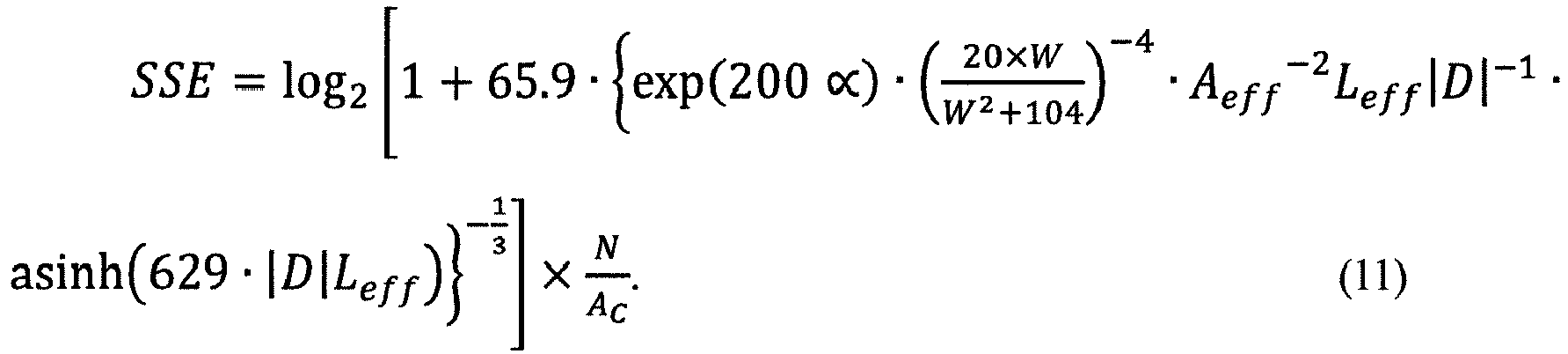
- A typical ribbon slotted-core optical fiber cable of related art has a cable diameter of about 12 mm in the case where the cable includes 40 fibers, about 17 mm in the case where the cable includes 100 fibers, and about 23 mm in the case where the cable includes 300 fibers. Also, an optical fiber housed in the optical fiber cable of related art uses standard SMF.
- A transmission loss of an optical fiber cable is equivalent to a transmission loss of an optical fiber if a bending loss or a micro-bending loss is not added when the optical fiber is housed in the cable. However, some optical fiber may have a transmission loss which is increased by a bending loss or a micro-bending loss when the optical fiber is housed in the cable. Alternatively, a bending loss or a micro-bending loss when an optical fiber is wound around a small-diameter bobbin may be released and a transmission loss may be decreased. A difference between a transmission loss after standard SMF is housed in a typical ribbon slotted-core cable of related art and a transmission loss of standard SMF was 0.00 dB/km in average and +0.018 dB/km in maximum.
- Then, if it is assumed that a value obtained by adding 0.02 dB/km to a transmission loss of the optical fiber (fiber transmission loss, fiber loss) serves as a transmission loss of a substantially standard optical fiber cable (cable transmission loss), Eq. (11) can be rewritten into Eq. (12):

- In contrast, the
optical fiber cable 10 has a cable diameter of about 11 mm, 13 mm, 17 mm, or 19 mm in the case where the cable includes 40 fibers, 100 fibers, 200 fibers, of 300 fibers respectively. Theoptical fiber cable 10 satisfies Eq. (13):
optical fiber 30 as described above. With Eq. (13), SSE can be increased by 30% or more as compared with the ribbon slotted-core optical fiber cable of related art including the same number of standard SMFs. More preferably, Eq. (14) is satisfied:

- The
optical fiber 30 housed in theoptical fiber cable 10 according to this embodiment is preferably a single core fiber for two reasons. - In a case of multi-core fiber, it is difficult to splice multi-core fibers of the same type with a low loss. When splicing is executed by using a fusion splicer, for example, misalignment in a range from about 0.2 to about 0.4 µm may be generated. In a multi-core fiber, since plural cores are housed in a single fiber, it is difficult to accurately align the axes of all cores. In general, the length of a single optical fiber cable arranged is in a range from about 1 to about 5 km. Hence, in a transmission line of a span length of 100 km, the number of same-type splicing portions is 20 to 100 portions per span. Owing to this, the total span loss is largely increased by the splice loss. Also, the multi-core fiber is connected to devices at both ends of the span, a device for branching each core is required, and the insertion loss thereof is added. Hence, the total loss is increased.
- The
optical fiber 30 preferably has the following features (1) to (5) at the wavelength of 1550 nm. - (1) The transmission loss is preferably 0.18 dB/km or less. As the transmission loss is decreased, SSE can be increased. The transmission loss is more preferably 0.17 dB/km or less.
- (2) Aeff is preferably in a range from 100 to 125 µm2. As Aeff is increased, γ is decreased. Hence, SSE can be increased. On the other hand, if Aeff is excessively increased, a confinement effect for propagation light in a core is decreased. Hence, the cable transmission loss becomes larger than that of standard SMF due to the bending loss and micro-bending loss when housed in the
optical fiber cable 10. - (3) MFD is preferably in a range from 11.0 to 12.5 µm. When same-type
optical fibers 30 are spliced by using a fusion splicer, for example, misalignment in a range from 0.2 to 0.4 µm may be generated.Figure 5 is a graph showing the relationship between a same-type splice loss and MFD. The horizontal axis indicates MFD at the wavelength of 1550 nm, and the vertical axis indicates the splice loss when the same-typeoptical fibers 30 are spliced. As MFD is increased, the splice loss can be suppressed at a lower value even with misalignment. In contrast, if MFD is excessively increased, the splice loss with respect to standard SMF used as a pigtail of a repeater is increased. - (4) A dispersion is preferably in a range from 19 to 22 ps/nm/km. As the dispersion is increased, SSE can be increased.
- (5) A fiber cutoff wavelength is preferably in a range from 1400 to 1600 nm. As the cutoff wavelength is increased, the bending loss can be suppressed at a lower value. The transmission loss after arrangement in the cable can be maintained at a lower value. However, if the cutoff wavelength is excessively increased, single-mode transmission is no longer executed.
-
Figures 6A and 6B are conceptual diagrams showing refractive index profiles ofoptical fibers 30 according to the embodiment. As shown inFig. 6A , one example of theoptical fiber 30 includes a core having a refractive index n1 and adiameter 2a [µm], and a cladding having a refractive index n2. In this case, if it is assumed that a relative refractive index difference of the core with respect to a refractive index n0 of pure silica Δ0 [%] is 100×(n1-n0)/n1 and a relative refractive index difference of the core with respect to the cladding Δ1 [%] is 100×(n1-n2)/n1, Δ1 is preferably in a range from 0.30% to 0.35% and 2a is preferably in a range from 10 to 13 µm. Also, Δ0 is preferably in a range from -0.1% to +0.1%. It is effective not to substantially add a dopant to the core through which a major part of power of an optical signal propagates, in order to decrease the fiber transmission loss. - As shown in
Fig. 6B , another example of theoptical fiber 30 includes a core having a refractive index n1 and adiameter 2a [µm], an inner cladding having a refractive index n2 and adiameter 2b [µm], and an outer cladding having a refractive index n3. The optical fiber has a depressed cladding type refractive index profile being n1 > n3 > n2. Since theoptical fiber 30 has the depressed cladding type refractive index profile, the bending loss can be suppressed at a relatively low value even when Aeff is increased. Hence, this example of theoptical fiber 30 is preferable. - In this case, if it is assumed that a relative refractive index difference of the core with respect to the refractive index n0 of pure silica Δ0 [%] is 100×(n1-n0)/n1, a relative refractive index difference of the core with respect to the inner cladding is Δ1 [%] = 100×(n1-n2)/n1, and a relative refractive index difference of the outer cladding with respect to the inner cladding is Δ2 [%] = 100×(n3-n2)/n3, Δ1 is preferably in a range from 0.30% to 0.35%, Δ2 is preferably in a range from 0.05% to 0.10%, 2a is preferably in a range from 10 to 13 µm, and 2b is preferably in a range from 40 to 55 µm. Also, Δ0 is preferably in a range from -0.1 % to +0.1%. It is effective not to substantially add a dopant to the core through which a major part of power of an optical signal propagates, in order to decrease the fiber transmission loss.
-
Figures 7A to 7F are illustrations showing index profiles of cores of optical fibers according to this embodiment, The index profile of the core of anoptical fiber 30 can be modified in any one of various shapes. In this case, it is assumed that the average value of refractive indices of a core is n1. - As described above, the
optical fiber cable 10 according to this embodiment houses the plurality ofoptical fibers 30 and satisfies Eq. (1). Accordingly, SSE of theoptical fiber cable 10 can be increased by 30% as compared with the ribbon slotted-core fiber cable of related art housing a standard single-mode fiber (standard SMF) when the numbers of optical fibers are the same. Also, since the transmission loss of theoptical fiber 30 at the wavelength of 1550 nm is 0.18 dB/km or less, and Aeff is in the range from 100 to 125 µm2, the transmission loss can be suppressed with an increased SSE value. - Also, since MFD of the optical fiber at the wavelength of 1550 nm is in the range from 11.0 to 12.5 µm, the splice loss between the same-type fibers can be suppressed at a low value even with misalignment, and the splice loss with respect to standard SMF used as the pigtail of the repeater can be suppressed at a low value. Also, since the dispersion of the
optical fiber 30 at the wavelength of 1550 nm is in the range from 19 to 22 ps/nm/km, SSE can be increased. Also, since the cutoff wavelength of theoptical fiber 30 is in the range from 1400 to 1600 nm, by increasing the cutoff wavelength of the optical fiber cable within a range available for single-mode transmission, the bending loss can be suppressed at a low value and the transmission loss of the optical fiber in the cable can be maintained at a low value. - Also, in the one example of the
optical fiber cable 10, theoptical fiber 30 includes the core and the cladding layer, the relative refractive index difference Δ1 of the core with respect to the cladding is in the range from 0.30% to 0.35%, and thediameter 2a of the core is in the range from 10 to 13 µm. Accordingly, SSE of theoptical fiber cable 10 can be increased. - Also, in the other example of the
optical fiber cable 10, theoptical fiber 30 includes the core, the inner cladding, and the outer cladding. The refractive index n3 of the outer cladding is smaller than the refractive index n1 of the core and is larger than the refractive index n2 of the inner cladding. The relative refractive index difference Δ2 of the outer cladding with respect to the inner cladding is in the range from 0.05% to 0.10%, the relative refractive index difference Δ1 of the core with respect to the inner cladding is in the range from 0.30% to 0.35%, and thediameter 2a of the core is in the range from 10 to 13 µm. Accordingly, even if Aeff is increased, the bending loss can be suppressed at a relatively low value, and SSE of the optical fiber cable can be increased. - Also, since the relative refractive index difference Δ0 of the core with respect to pure silica is in the range from -0.1 % to +0.1%, and a dopant is not substantially added to the core through which the major part of the power of the optical signal propagates, the transmission loss of the
optical fiber 30 can be decreased. - Also, the
optical fiber cable 10 is the ribbon slotted-core cable. The value Aslot obtained by dividing the sectional area of thesingle slot 2 by the number of optical fibers Nslot housed in thesingle slot 2 is in the range from 0.12 to 0.16 mm2/core. If the sectional area (x1+x2)×y/2 of theslot 2 is decreased, the sectional area of the cable can be decreased. This is advantageous to increase SSE of theoptical fiber cable 10. However, if the sectional area of theslot 2 is excessively decreased, the clearance with respect to thefiber ribbon 20 is decreased. Accordingly, thefiber ribbon 20 contacts the inner wall of theslot 2, and the bending loss and micro-bending loss are generated by the stress of theoptical fiber 30. Consequently, the loss is increased more than the loss of the cable of related art, and SSE is decreased. Particularly in a case of an optical fiber having Aeff being larger than that of standard SMF like theoptical fiber 30 according to this embodiment, the confinement for the propagation light in the core is weakened, and the bending loss and micro-bending loss are likely generated. In this embodiment, since Aslot is determined within the predetermined range, even if the above-describedoptical fiber 30 is housed, the sectional area of the cable can be decreased while the difference in transmission loss between theoptical fiber 30 and theoptical fiber cable 10 is suppressed to be equivalent to a case in which standard SMF is housed in the typical ribbon slotted-core cable of related art. Consequently, SSE of theoptical fiber cable 10 can be increased. - Also, the
optical fiber cable 10 is the ribbon slotted-core cable, the value Aslot obtained by dividing the sectional area of thesingle slot 2 by the number of optical fibers Nslot housed in thesingle slot 2 is in the range from 0.12 to 0.16 mm2/core, the transmission loss of theoptical fiber 30 at the wavelength of 1550 nm is 0.18 dB/km or lower, and Aeff is in the range from 100 to 125 µm2. In this case, as described above, since Aslot is determined within the predetermined range, even if the above-describedoptical fiber 30 is housed, the sectional area of the cable can be decreased while the difference in transmission loss between theoptical fiber 30 and theoptical fiber cable 10 is suppressed to be equivalent to the case in which standard SMF is housed in the typical ribbon slotted-core cable of related art. Consequently, SSE of theoptical fiber cable 10 can be increased. Also, the transmission loss can be suppressed with an increased SSE value. - Next, specific examples of the optical fiber according to this embodiment are described in comparison with a comparative example. An optical fiber according to Example 1 was an optical fiber having a refractive index profile as shown in
Fig. 6A . Optical fibers according to Examples 2 to 5 were optical fibers each having a depressed cladding type refractive index profile as shown inFig. 6B . An optical fiber according to the comparative example was standard SMF. -
Figure 8 is a table showing structures of optical fibers and optical characteristics at the wavelength of 1550 nm according to the comparative example and the examples.Figure 9 is a table showing SSE when the optical fibers according to the examples were housed in optical fiber cables. The difference between the cable transmission loss when the optical fiber according to any one of the examples was housed in the optical fiber cable according to the embodiment of the invention and the transmission loss shown inFig. 8 was 0.02 dB/km or less even at maximum, which is substantially equivalent to a case in which standard SMF is housed in the typical ribbon slotted-core cable of related art. Hence, similarly to the case in which standard SMF is housed in the typical ribbon slotted-core cable of related art, SSE was obtained from Eq. (11) while the value obtained by adding 0.02 dB/km to the fiber transmission loss was treated as a substantially standard cable transmission loss. InFig. 9 , "Y" was applied if obtained SSE satisfied Eqs. (13) to (15), and "N" was applied if obtained SSE did not satisfy Eqs. (13) to (15). -
Figures 10A, 10B ,11A, and 11B are graphs each showing the relationship between Aeff of an optical fiber at the wavelength of 1550 nm and SSE of an optical fiber cable.Figures 10A, 10B ,11A, and 11B shows the cases in which the optical fiber cable includes 40 fibers, 100fibers 200 fibers, and 300 fibers, respectively. Each figure shows the relationship between Aeff of the optical fiber at the wavelength of 1550 nm and SSE of the optical fiber cable, for each of cases of fiber transmission losses being 0.180, 0.170, and 0.160 dB/km. Also, each figure shows the values of the right sides in Eqs. (13) to (15). - In the range of Aeff from 70 to 125 µm2, the difference in transmission loss between the cable and the fiber is 0.02 dB/km or smaller even at maximum, and similarly to the case in which standard SMF is housed in the typical ribbon slotted-core cable of related art, the value obtained by adding 0.02 dB/km to the fiber transmission loss is treated as a substantially standard cable transmission loss. Referring to
Figs. 10A, 10B ,11A, and 11B , as long as Aeff is 100 µm2 or larger and the fiber transmission loss is 0.180 dB/km or lower, Eq. (13) can be satisfied. -
Figure 12 is a table showing slot sizes and other specifications of optical fiber cables according to examples. As shown inFig. 12 , with the optical fiber cable according to any one of the examples, Aslot is set in the range from 0.12 to 0.16 mm2/core. Accordingly, even when the optical fiber is housed, the sectional area of the cable can be decreased while the difference in transmission loss between the optical fiber and the optical fiber cable is suppressed to be equivalent to the case in which standard SMF is housed in the typical ribbon slotted-core cable of related art.
Claims (9)
- An optical fiber cable having a sectional area of Ac [µm2] and housing a number N of optical fibers,
wherein a transmission loss αdB [dB/km], a mode field diameter W [µm], an effective area Aeff [µm2], an effective length Leff [km], and a wavelength dispersion D [ps/nm/km] of each of the optical fibers at a wavelength of 1550 nm satisfy Equation (1),
- The optical fiber cable according to Claim 1,
wherein the transmission loss of the optical fiber at the wavelength of 1550 nm is 0.18 dB/km or less, and the effective area of the optical fiber is in a range from 100 to 125 µm2. - The optical fiber cable according to Claim 1 or 2,
wherein the mode field diameter of the optical fiber at the wavelength of 1550 nm is in a range from 11.0 to 12.5 µm. - The optical fiber cable according to any one of Claims 1 to 3,
wherein the wavelength dispersion of the optical fiber at the wavelength of 1550 nm is in a range from 19 to 22 ps/nm/km. - The optical fiber cable according to any one of Claims 1 to 4,
wherein the optical fiber has a cutoff wavelength in a range from 1400 to 1600 nm. - The optical fiber cable according to any one of Claims 1 to 5,
wherein the optical fiber comprises:a core having a diameter in a range from 10 to 13 µm; anda cladding surrounding the core and having a refractive index that is smaller than a refractive index of the core,wherein a relative refractive index difference of the core with respect to the cladding is in a range from 0.30% to 0.35%. - The optical fiber cable according to any one of Claims 1 to 5,
wherein the optical fiber comprises:a core having a diameter in a range from 10 to 13 µm;an inner cladding surrounding the core and having a refractive index that is smaller than a refractive index of the core; andan outer cladding having a refractive index that is smaller than a refractive index of the core and larger than a refractive index of the inner cladding,wherein a relative refractive index difference of the outer cladding with respect to the inner cladding is in a range from 0.05% to 0.10%, and a relative refractive index difference of the core with respect to the inner cladding is in a range from 0.30% to 0.35%. - The optical fiber cable according to Claim 6 or 7,
wherein a relative refractive index difference of the core with respect to pure silica is in a range from -0.1% to +0.1%. - The optical fiber cable according to any one of Claims 1 to 8,
wherein the optical fiber cable is a ribbon slotted-core cable, and
wherein a value obtained by dividing a sectional area of a single slot by a number of cores of the optical fibers housed in the single slot is in a range from 0.12 to 0.16 mm2/core.
Applications Claiming Priority (1)
| Application Number | Priority Date | Filing Date | Title |
|---|---|---|---|
| JP2015075141A JP6554875B2 (en) | 2015-04-01 | 2015-04-01 | Fiber optic cable |
Publications (2)
| Publication Number | Publication Date |
|---|---|
| EP3088930A1 true EP3088930A1 (en) | 2016-11-02 |
| EP3088930B1 EP3088930B1 (en) | 2019-09-18 |
Family
ID=55637271
Family Applications (1)
| Application Number | Title | Priority Date | Filing Date |
|---|---|---|---|
| EP16162554.6A Active EP3088930B1 (en) | 2015-04-01 | 2016-03-29 | Optical fiber cable |
Country Status (5)
| Country | Link |
|---|---|
| US (1) | US9696508B2 (en) |
| EP (1) | EP3088930B1 (en) |
| JP (1) | JP6554875B2 (en) |
| CN (1) | CN106054330B (en) |
| DK (1) | DK3088930T3 (en) |
Families Citing this family (8)
| Publication number | Priority date | Publication date | Assignee | Title |
|---|---|---|---|---|
| US9645340B2 (en) | 2015-04-01 | 2017-05-09 | Sumitomo Electric Industries, Ltd. | Optical fiber cable |
| JPWO2018230618A1 (en) * | 2017-06-14 | 2020-04-16 | 住友電気工業株式会社 | Slotted optical cable |
| WO2022086863A1 (en) * | 2020-10-22 | 2022-04-28 | Ofs Fitel, Llc | Increasing total data capacity in optical transmission systems |
| WO2022102666A1 (en) * | 2020-11-11 | 2022-05-19 | 住友電気工業株式会社 | Optical fiber cable |
| JP7898449B2 (en) * | 2021-08-25 | 2026-07-31 | 住友電気工業株式会社 | Fiber optic cable |
| US20240310575A1 (en) * | 2023-03-17 | 2024-09-19 | Furukawa Electric Co., Ltd. | Optical fiber connection structure and manufacturing method thereof |
| WO2025120734A1 (en) * | 2023-12-05 | 2025-06-12 | 日本電信電話株式会社 | Measurement device and measurement method |
| WO2026071175A1 (en) * | 2024-09-30 | 2026-04-02 | 古河電気工業株式会社 | Cable shape sensing system and power cable |
Citations (7)
| Publication number | Priority date | Publication date | Assignee | Title |
|---|---|---|---|---|
| EP0503469A2 (en) * | 1991-03-08 | 1992-09-16 | PIRELLI CAVI S.p.A. | Grooved-core cable with optical fibre ribbons and process for making the same |
| EP1107027A1 (en) * | 1999-04-13 | 2001-06-13 | Sumitomo Electric Industries, Ltd. | Optical fiber and optical communication system comprising the same |
| EP1154294A1 (en) * | 1999-01-18 | 2001-11-14 | Sumitomo Electric Industries, Ltd. | Optical fiber and method of manufacture thereof |
| US20020106172A1 (en) * | 1998-12-17 | 2002-08-08 | Sumitomo Electric Industries, Ltd. | Optical fiber |
| US20050089289A1 (en) * | 2002-10-01 | 2005-04-28 | The Furukawa Electric Co, Ltd. | Optical fiber, method for manufacturing same and optical transmission channel |
| JP2013129234A (en) | 2011-12-20 | 2013-07-04 | Bridgestone Corp | Bead core and tire using the same |
| JP2014067020A (en) | 2012-09-04 | 2014-04-17 | Sumitomo Electric Ind Ltd | Optical fiber |
Family Cites Families (9)
| Publication number | Priority date | Publication date | Assignee | Title |
|---|---|---|---|---|
| CN100516955C (en) * | 2002-11-06 | 2009-07-22 | 住友电气工业株式会社 | Optical fiber ribbon and optical fiber cable using the same |
| JP2005037936A (en) * | 2003-07-01 | 2005-02-10 | Sumitomo Electric Ind Ltd | Fiber optic cable |
| US7099544B2 (en) * | 2003-12-19 | 2006-08-29 | Corning Incorporated | High SBS threshold NZDS optical fiber |
| JP2007272060A (en) | 2006-03-31 | 2007-10-18 | Furukawa Electric Co Ltd:The | Optical fiber ribbon core and optical fiber cable |
| JP2007286319A (en) * | 2006-04-17 | 2007-11-01 | Furukawa Electric Co Ltd:The | Fiber optic cable |
| US8768129B2 (en) * | 2011-09-21 | 2014-07-01 | Ofs Fitel, Llc | Optimized ultra large area optical fibers |
| JP5255690B2 (en) | 2011-12-27 | 2013-08-07 | 古河電気工業株式会社 | Optical fiber colored core, optical fiber tape, and optical fiber cable |
| CN104145198B (en) | 2012-02-29 | 2018-06-15 | 住友电气工业株式会社 | Multi-core optical fiber, multi-core optical fiber cable and multi-core optical fiber transmission system |
| US9645340B2 (en) * | 2015-04-01 | 2017-05-09 | Sumitomo Electric Industries, Ltd. | Optical fiber cable |
-
2015
- 2015-04-01 JP JP2015075141A patent/JP6554875B2/en active Active
-
2016
- 2016-03-29 DK DK16162554.6T patent/DK3088930T3/en active
- 2016-03-29 EP EP16162554.6A patent/EP3088930B1/en active Active
- 2016-03-30 US US15/084,784 patent/US9696508B2/en active Active
- 2016-03-31 CN CN201610196340.5A patent/CN106054330B/en active Active
Patent Citations (7)
| Publication number | Priority date | Publication date | Assignee | Title |
|---|---|---|---|---|
| EP0503469A2 (en) * | 1991-03-08 | 1992-09-16 | PIRELLI CAVI S.p.A. | Grooved-core cable with optical fibre ribbons and process for making the same |
| US20020106172A1 (en) * | 1998-12-17 | 2002-08-08 | Sumitomo Electric Industries, Ltd. | Optical fiber |
| EP1154294A1 (en) * | 1999-01-18 | 2001-11-14 | Sumitomo Electric Industries, Ltd. | Optical fiber and method of manufacture thereof |
| EP1107027A1 (en) * | 1999-04-13 | 2001-06-13 | Sumitomo Electric Industries, Ltd. | Optical fiber and optical communication system comprising the same |
| US20050089289A1 (en) * | 2002-10-01 | 2005-04-28 | The Furukawa Electric Co, Ltd. | Optical fiber, method for manufacturing same and optical transmission channel |
| JP2013129234A (en) | 2011-12-20 | 2013-07-04 | Bridgestone Corp | Bead core and tire using the same |
| JP2014067020A (en) | 2012-09-04 | 2014-04-17 | Sumitomo Electric Ind Ltd | Optical fiber |
Non-Patent Citations (2)
| Title |
|---|
| M. HIRANO ET AL.: "Analytical OSNR Formulation Validated with 100G-WDM Experiments and Optimal Subsea Fiber Proposal", OFC/NFOEC TECHNICAL DIGEST, 2013 |
| R. ESSIAMBRE ET AL.: "Capacity Limits of Optical Fiber Networks", JOURNAL OF LIGHTWAVE TECHNOLOGY, vol. 28, no. 4, February 2010 (2010-02-01), pages 662 - 701, XP011290062, DOI: doi:10.1109/JLT.2009.2039464 |
Also Published As
| Publication number | Publication date |
|---|---|
| DK3088930T3 (en) | 2019-10-21 |
| CN106054330A (en) | 2016-10-26 |
| JP2016194652A (en) | 2016-11-17 |
| US20160291278A1 (en) | 2016-10-06 |
| CN106054330B (en) | 2019-10-22 |
| JP6554875B2 (en) | 2019-08-07 |
| EP3088930B1 (en) | 2019-09-18 |
| US9696508B2 (en) | 2017-07-04 |
Similar Documents
| Publication | Publication Date | Title |
|---|---|---|
| EP3088930B1 (en) | Optical fiber cable | |
| EP2821823B1 (en) | Multicore optical fiber, multicore optical fiber cable, and multicore optical fiber transmission system | |
| Takenaga et al. | Reduction of crosstalk by trench-assisted multi-core fiber | |
| US9088364B1 (en) | Optical transmission system and multi-core optical fiber | |
| Yoshizawa et al. | Stimulated Brillouin scattering suppression by means of applying strain distribution to fiber with cabling | |
| CN101281275B (en) | Transmission optical fiber having large effective area | |
| US9081129B2 (en) | Multi-core fiber | |
| US20140064686A1 (en) | Multiple lp mode fiber designs for mode division multiplexing | |
| EP2894498A1 (en) | Optical fiber | |
| Peckham et al. | Few-mode fiber technology for spatial multiplexing | |
| KR20030061676A (en) | Optical fiber, optical fiber tape, optical cable, and optical connector with optical fiber | |
| US20170031088A1 (en) | Optical fiber cable | |
| KR102848777B1 (en) | fiber optic cable | |
| Sillard | New fibers for ultra-high capacity transport | |
| US9645340B2 (en) | Optical fiber cable | |
| Sasaki et al. | Large-effective-area uncoupled 10-core fiber with two-pitch layout | |
| Imada et al. | Applicability of Homogeneous/Heterogeneous Multi-core Fibers for Submarine Cables | |
| KR102848778B1 (en) | fiber optic cable | |
| Zhu et al. | Advanced Low-Loss Fibers for High-Capacity Transmission: from Data Center to Undersea | |
| Haruna et al. | Applicability of Aeff-enlarged pure-silica-core fiber for C-and L-band transmission | |
| Sahu et al. | Multi-element fiber for space-division multiplexing | |
| Zhu | Recent advances in transmission fibers for next generation optical network | |
| KR100488625B1 (en) | Products consisting of optical fibers suitable for use in wavelength division multiplexing systems | |
| JP2023547374A (en) | Increase in total data capacity in optical transmission systems | |
| Sillard et al. | Optical Fibers |
Legal Events
| Date | Code | Title | Description |
|---|---|---|---|
| PUAI | Public reference made under article 153(3) epc to a published international application that has entered the european phase |
Free format text: ORIGINAL CODE: 0009012 |
|
| AK | Designated contracting states |
Kind code of ref document: A1 Designated state(s): AL AT BE BG CH CY CZ DE DK EE ES FI FR GB GR HR HU IE IS IT LI LT LU LV MC MK MT NL NO PL PT RO RS SE SI SK SM TR |
|
| AX | Request for extension of the european patent |
Extension state: BA ME |
|
| STAA | Information on the status of an ep patent application or granted ep patent |
Free format text: STATUS: REQUEST FOR EXAMINATION WAS MADE |
|
| 17P | Request for examination filed |
Effective date: 20170425 |
|
| RBV | Designated contracting states (corrected) |
Designated state(s): AL AT BE BG CH CY CZ DE DK EE ES FI FR GB GR HR HU IE IS IT LI LT LU LV MC MK MT NL NO PL PT RO RS SE SI SK SM TR |
|
| STAA | Information on the status of an ep patent application or granted ep patent |
Free format text: STATUS: EXAMINATION IS IN PROGRESS |
|
| 17Q | First examination report despatched |
Effective date: 20180202 |
|
| GRAP | Despatch of communication of intention to grant a patent |
Free format text: ORIGINAL CODE: EPIDOSNIGR1 |
|
| STAA | Information on the status of an ep patent application or granted ep patent |
Free format text: STATUS: GRANT OF PATENT IS INTENDED |
|
| INTG | Intention to grant announced |
Effective date: 20190527 |
|
| GRAS | Grant fee paid |
Free format text: ORIGINAL CODE: EPIDOSNIGR3 |
|
| GRAA | (expected) grant |
Free format text: ORIGINAL CODE: 0009210 |
|
| STAA | Information on the status of an ep patent application or granted ep patent |
Free format text: STATUS: THE PATENT HAS BEEN GRANTED |
|
| AK | Designated contracting states |
Kind code of ref document: B1 Designated state(s): AL AT BE BG CH CY CZ DE DK EE ES FI FR GB GR HR HU IE IS IT LI LT LU LV MC MK MT NL NO PL PT RO RS SE SI SK SM TR |
|
| REG | Reference to a national code |
Ref country code: GB Ref legal event code: FG4D |
|
| REG | Reference to a national code |
Ref country code: CH Ref legal event code: EP |
|
| REG | Reference to a national code |
Ref country code: DE Ref legal event code: R096 Ref document number: 602016020681 Country of ref document: DE |
|
| REG | Reference to a national code |
Ref country code: AT Ref legal event code: REF Ref document number: 1182009 Country of ref document: AT Kind code of ref document: T Effective date: 20191015 |
|
| REG | Reference to a national code |
Ref country code: IE Ref legal event code: FG4D |
|
| REG | Reference to a national code |
Ref country code: DK Ref legal event code: T3 Effective date: 20191015 |
|
| REG | Reference to a national code |
Ref country code: NL Ref legal event code: FP |
|
| PG25 | Lapsed in a contracting state [announced via postgrant information from national office to epo] |
Ref country code: NO Free format text: LAPSE BECAUSE OF FAILURE TO SUBMIT A TRANSLATION OF THE DESCRIPTION OR TO PAY THE FEE WITHIN THE PRESCRIBED TIME-LIMIT Effective date: 20191218 Ref country code: SE Free format text: LAPSE BECAUSE OF FAILURE TO SUBMIT A TRANSLATION OF THE DESCRIPTION OR TO PAY THE FEE WITHIN THE PRESCRIBED TIME-LIMIT Effective date: 20190918 Ref country code: BG Free format text: LAPSE BECAUSE OF FAILURE TO SUBMIT A TRANSLATION OF THE DESCRIPTION OR TO PAY THE FEE WITHIN THE PRESCRIBED TIME-LIMIT Effective date: 20191218 Ref country code: FI Free format text: LAPSE BECAUSE OF FAILURE TO SUBMIT A TRANSLATION OF THE DESCRIPTION OR TO PAY THE FEE WITHIN THE PRESCRIBED TIME-LIMIT Effective date: 20190918 Ref country code: HR Free format text: LAPSE BECAUSE OF FAILURE TO SUBMIT A TRANSLATION OF THE DESCRIPTION OR TO PAY THE FEE WITHIN THE PRESCRIBED TIME-LIMIT Effective date: 20190918 Ref country code: LT Free format text: LAPSE BECAUSE OF FAILURE TO SUBMIT A TRANSLATION OF THE DESCRIPTION OR TO PAY THE FEE WITHIN THE PRESCRIBED TIME-LIMIT Effective date: 20190918 |
|
| REG | Reference to a national code |
Ref country code: LT Ref legal event code: MG4D |
|
| PG25 | Lapsed in a contracting state [announced via postgrant information from national office to epo] |
Ref country code: GR Free format text: LAPSE BECAUSE OF FAILURE TO SUBMIT A TRANSLATION OF THE DESCRIPTION OR TO PAY THE FEE WITHIN THE PRESCRIBED TIME-LIMIT Effective date: 20191219 Ref country code: RS Free format text: LAPSE BECAUSE OF FAILURE TO SUBMIT A TRANSLATION OF THE DESCRIPTION OR TO PAY THE FEE WITHIN THE PRESCRIBED TIME-LIMIT Effective date: 20190918 Ref country code: LV Free format text: LAPSE BECAUSE OF FAILURE TO SUBMIT A TRANSLATION OF THE DESCRIPTION OR TO PAY THE FEE WITHIN THE PRESCRIBED TIME-LIMIT Effective date: 20190918 Ref country code: AL Free format text: LAPSE BECAUSE OF FAILURE TO SUBMIT A TRANSLATION OF THE DESCRIPTION OR TO PAY THE FEE WITHIN THE PRESCRIBED TIME-LIMIT Effective date: 20190918 |
|
| REG | Reference to a national code |
Ref country code: AT Ref legal event code: MK05 Ref document number: 1182009 Country of ref document: AT Kind code of ref document: T Effective date: 20190918 |
|
| PG25 | Lapsed in a contracting state [announced via postgrant information from national office to epo] |
Ref country code: ES Free format text: LAPSE BECAUSE OF FAILURE TO SUBMIT A TRANSLATION OF THE DESCRIPTION OR TO PAY THE FEE WITHIN THE PRESCRIBED TIME-LIMIT Effective date: 20190918 Ref country code: EE Free format text: LAPSE BECAUSE OF FAILURE TO SUBMIT A TRANSLATION OF THE DESCRIPTION OR TO PAY THE FEE WITHIN THE PRESCRIBED TIME-LIMIT Effective date: 20190918 Ref country code: PL Free format text: LAPSE BECAUSE OF FAILURE TO SUBMIT A TRANSLATION OF THE DESCRIPTION OR TO PAY THE FEE WITHIN THE PRESCRIBED TIME-LIMIT Effective date: 20190918 Ref country code: PT Free format text: LAPSE BECAUSE OF FAILURE TO SUBMIT A TRANSLATION OF THE DESCRIPTION OR TO PAY THE FEE WITHIN THE PRESCRIBED TIME-LIMIT Effective date: 20200120 Ref country code: RO Free format text: LAPSE BECAUSE OF FAILURE TO SUBMIT A TRANSLATION OF THE DESCRIPTION OR TO PAY THE FEE WITHIN THE PRESCRIBED TIME-LIMIT Effective date: 20190918 Ref country code: IT Free format text: LAPSE BECAUSE OF FAILURE TO SUBMIT A TRANSLATION OF THE DESCRIPTION OR TO PAY THE FEE WITHIN THE PRESCRIBED TIME-LIMIT Effective date: 20190918 Ref country code: AT Free format text: LAPSE BECAUSE OF FAILURE TO SUBMIT A TRANSLATION OF THE DESCRIPTION OR TO PAY THE FEE WITHIN THE PRESCRIBED TIME-LIMIT Effective date: 20190918 |
|
| PG25 | Lapsed in a contracting state [announced via postgrant information from national office to epo] |
Ref country code: IS Free format text: LAPSE BECAUSE OF FAILURE TO SUBMIT A TRANSLATION OF THE DESCRIPTION OR TO PAY THE FEE WITHIN THE PRESCRIBED TIME-LIMIT Effective date: 20200224 Ref country code: CZ Free format text: LAPSE BECAUSE OF FAILURE TO SUBMIT A TRANSLATION OF THE DESCRIPTION OR TO PAY THE FEE WITHIN THE PRESCRIBED TIME-LIMIT Effective date: 20190918 Ref country code: SM Free format text: LAPSE BECAUSE OF FAILURE TO SUBMIT A TRANSLATION OF THE DESCRIPTION OR TO PAY THE FEE WITHIN THE PRESCRIBED TIME-LIMIT Effective date: 20190918 Ref country code: SK Free format text: LAPSE BECAUSE OF FAILURE TO SUBMIT A TRANSLATION OF THE DESCRIPTION OR TO PAY THE FEE WITHIN THE PRESCRIBED TIME-LIMIT Effective date: 20190918 |
|
| REG | Reference to a national code |
Ref country code: DE Ref legal event code: R097 Ref document number: 602016020681 Country of ref document: DE |
|
| PLBE | No opposition filed within time limit |
Free format text: ORIGINAL CODE: 0009261 |
|
| STAA | Information on the status of an ep patent application or granted ep patent |
Free format text: STATUS: NO OPPOSITION FILED WITHIN TIME LIMIT |
|
| PG2D | Information on lapse in contracting state deleted |
Ref country code: IS |
|
| PG25 | Lapsed in a contracting state [announced via postgrant information from national office to epo] |
Ref country code: IS Free format text: LAPSE BECAUSE OF FAILURE TO SUBMIT A TRANSLATION OF THE DESCRIPTION OR TO PAY THE FEE WITHIN THE PRESCRIBED TIME-LIMIT Effective date: 20200119 |
|
| 26N | No opposition filed |
Effective date: 20200619 |
|
| PG25 | Lapsed in a contracting state [announced via postgrant information from national office to epo] |
Ref country code: SI Free format text: LAPSE BECAUSE OF FAILURE TO SUBMIT A TRANSLATION OF THE DESCRIPTION OR TO PAY THE FEE WITHIN THE PRESCRIBED TIME-LIMIT Effective date: 20190918 |
|
| REG | Reference to a national code |
Ref country code: DE Ref legal event code: R119 Ref document number: 602016020681 Country of ref document: DE |
|
| PG25 | Lapsed in a contracting state [announced via postgrant information from national office to epo] |
Ref country code: MC Free format text: LAPSE BECAUSE OF FAILURE TO SUBMIT A TRANSLATION OF THE DESCRIPTION OR TO PAY THE FEE WITHIN THE PRESCRIBED TIME-LIMIT Effective date: 20190918 |
|
| REG | Reference to a national code |
Ref country code: CH Ref legal event code: PL |
|
| REG | Reference to a national code |
Ref country code: BE Ref legal event code: MM Effective date: 20200331 |
|
| PG25 | Lapsed in a contracting state [announced via postgrant information from national office to epo] |
Ref country code: LU Free format text: LAPSE BECAUSE OF NON-PAYMENT OF DUE FEES Effective date: 20200329 |
|
| PG25 | Lapsed in a contracting state [announced via postgrant information from national office to epo] |
Ref country code: LI Free format text: LAPSE BECAUSE OF NON-PAYMENT OF DUE FEES Effective date: 20200331 Ref country code: DE Free format text: LAPSE BECAUSE OF NON-PAYMENT OF DUE FEES Effective date: 20201001 Ref country code: CH Free format text: LAPSE BECAUSE OF NON-PAYMENT OF DUE FEES Effective date: 20200331 Ref country code: IE Free format text: LAPSE BECAUSE OF NON-PAYMENT OF DUE FEES Effective date: 20200329 |
|
| PG25 | Lapsed in a contracting state [announced via postgrant information from national office to epo] |
Ref country code: BE Free format text: LAPSE BECAUSE OF NON-PAYMENT OF DUE FEES Effective date: 20200331 |
|
| GBPC | Gb: european patent ceased through non-payment of renewal fee |
Effective date: 20200329 |
|
| PG25 | Lapsed in a contracting state [announced via postgrant information from national office to epo] |
Ref country code: GB Free format text: LAPSE BECAUSE OF NON-PAYMENT OF DUE FEES Effective date: 20200329 |
|
| PG25 | Lapsed in a contracting state [announced via postgrant information from national office to epo] |
Ref country code: TR Free format text: LAPSE BECAUSE OF FAILURE TO SUBMIT A TRANSLATION OF THE DESCRIPTION OR TO PAY THE FEE WITHIN THE PRESCRIBED TIME-LIMIT Effective date: 20190918 Ref country code: MT Free format text: LAPSE BECAUSE OF FAILURE TO SUBMIT A TRANSLATION OF THE DESCRIPTION OR TO PAY THE FEE WITHIN THE PRESCRIBED TIME-LIMIT Effective date: 20190918 Ref country code: CY Free format text: LAPSE BECAUSE OF FAILURE TO SUBMIT A TRANSLATION OF THE DESCRIPTION OR TO PAY THE FEE WITHIN THE PRESCRIBED TIME-LIMIT Effective date: 20190918 |
|
| PG25 | Lapsed in a contracting state [announced via postgrant information from national office to epo] |
Ref country code: MK Free format text: LAPSE BECAUSE OF FAILURE TO SUBMIT A TRANSLATION OF THE DESCRIPTION OR TO PAY THE FEE WITHIN THE PRESCRIBED TIME-LIMIT Effective date: 20190918 |
|
| P01 | Opt-out of the competence of the unified patent court (upc) registered |
Effective date: 20230515 |
|
| PGFP | Annual fee paid to national office [announced via postgrant information from national office to epo] |
Ref country code: NL Payment date: 20260213 Year of fee payment: 11 |
|
| PGFP | Annual fee paid to national office [announced via postgrant information from national office to epo] |
Ref country code: DK Payment date: 20260313 Year of fee payment: 11 |
|
| PGFP | Annual fee paid to national office [announced via postgrant information from national office to epo] |
Ref country code: FR Payment date: 20260209 Year of fee payment: 11 |