EP3088925A1 - Method for manufacturing multicore-optical-fiber connector and multicore optical fiber - Google Patents
Method for manufacturing multicore-optical-fiber connector and multicore optical fiber Download PDFInfo
- Publication number
- EP3088925A1 EP3088925A1 EP14874376.8A EP14874376A EP3088925A1 EP 3088925 A1 EP3088925 A1 EP 3088925A1 EP 14874376 A EP14874376 A EP 14874376A EP 3088925 A1 EP3088925 A1 EP 3088925A1
- Authority
- EP
- European Patent Office
- Prior art keywords
- core optical
- marker
- optical fibers
- cores
- straight line
- Prior art date
- Legal status (The legal status is an assumption and is not a legal conclusion. Google has not performed a legal analysis and makes no representation as to the accuracy of the status listed.)
- Granted
Links
Images





Classifications
-
- G—PHYSICS
- G02—OPTICS
- G02B—OPTICAL ELEMENTS, SYSTEMS OR APPARATUS
- G02B6/00—Light guides; Structural details of arrangements comprising light guides and other optical elements, e.g. couplings
- G02B6/24—Coupling light guides
- G02B6/36—Mechanical coupling means
- G02B6/38—Mechanical coupling means having fibre to fibre mating means
- G02B6/3807—Dismountable connectors, i.e. comprising plugs
- G02B6/3833—Details of mounting fibres in ferrules; Assembly methods; Manufacture
- G02B6/3834—Means for centering or aligning the light guide within the ferrule
- G02B6/3843—Means for centering or aligning the light guide within the ferrule with auxiliary facilities for movably aligning or adjusting the fibre within its ferrule, e.g. measuring position or eccentricity
-
- G—PHYSICS
- G02—OPTICS
- G02B—OPTICAL ELEMENTS, SYSTEMS OR APPARATUS
- G02B6/00—Light guides; Structural details of arrangements comprising light guides and other optical elements, e.g. couplings
- G02B6/02—Optical fibres with cladding with or without a coating
- G02B6/02042—Multicore optical fibres
-
- G—PHYSICS
- G02—OPTICS
- G02B—OPTICAL ELEMENTS, SYSTEMS OR APPARATUS
- G02B6/00—Light guides; Structural details of arrangements comprising light guides and other optical elements, e.g. couplings
- G02B6/24—Coupling light guides
- G02B6/245—Removing protective coverings of light guides before coupling
-
- G—PHYSICS
- G02—OPTICS
- G02B—OPTICAL ELEMENTS, SYSTEMS OR APPARATUS
- G02B6/00—Light guides; Structural details of arrangements comprising light guides and other optical elements, e.g. couplings
- G02B6/24—Coupling light guides
- G02B6/36—Mechanical coupling means
- G02B6/38—Mechanical coupling means having fibre to fibre mating means
- G02B6/3807—Dismountable connectors, i.e. comprising plugs
- G02B6/3833—Details of mounting fibres in ferrules; Assembly methods; Manufacture
- G02B6/3834—Means for centering or aligning the light guide within the ferrule
- G02B6/3838—Means for centering or aligning the light guide within the ferrule using grooves for light guides
- G02B6/3839—Means for centering or aligning the light guide within the ferrule using grooves for light guides for a plurality of light guides
-
- G—PHYSICS
- G02—OPTICS
- G02B—OPTICAL ELEMENTS, SYSTEMS OR APPARATUS
- G02B6/00—Light guides; Structural details of arrangements comprising light guides and other optical elements, e.g. couplings
- G02B6/24—Coupling light guides
- G02B6/36—Mechanical coupling means
- G02B6/38—Mechanical coupling means having fibre to fibre mating means
- G02B6/3807—Dismountable connectors, i.e. comprising plugs
- G02B6/3873—Connectors using guide surfaces for aligning ferrule ends, e.g. tubes, sleeves, V-grooves, rods, pins, balls
- G02B6/3885—Multicore or multichannel optical connectors, i.e. one single ferrule containing more than one fibre, e.g. ribbon type
-
- G—PHYSICS
- G02—OPTICS
- G02B—OPTICAL ELEMENTS, SYSTEMS OR APPARATUS
- G02B6/00—Light guides; Structural details of arrangements comprising light guides and other optical elements, e.g. couplings
- G02B6/24—Coupling light guides
- G02B6/36—Mechanical coupling means
- G02B6/3628—Mechanical coupling means for mounting fibres to supporting carriers
- G02B6/3648—Supporting carriers of a microbench type, i.e. with micromachined additional mechanical structures
- G02B6/3652—Supporting carriers of a microbench type, i.e. with micromachined additional mechanical structures the additional structures being prepositioning mounting areas, allowing only movement in one dimension, e.g. grooves, trenches or vias in the microbench surface, i.e. self aligning supporting carriers
Definitions
- the present invention relates to a multi-core optical fiber (hereinafter referred to as "MCF”) and a method for manufacturing a multi-core optical fiber connector (hereinafter referred to as "MCF connector").
- MCF multi-core optical fiber
- MCF connector a method for manufacturing a multi-core optical fiber connector
- An MCF is comprised of a plurality of cores extending along a fiber axis direction (which is a direction coinciding with the longitudinal direction of the MCF and extending along the fiber axis passing a center of a cross section of the MCF perpendicular to the longitudinal direction), and a common cladding covering each of these cores.
- Each of the cores optically functions as an optical waveguide. Since the MCF has a larger number of cores per unit cross-sectional area than a single-core fiber does, it is suitable for transmission of large volumes of information.
- Patent Literature 1 discloses an example of implementing optical axis alignment between the MCFs by making use of marker portions provided in the respective MCFs. Specifically, in a fusion splice operation, first, while monitoring the side faces of the two MCFs as splicing objects, each of the MCFs is rotated around the fiber axis and the two MCFs are checked as to positions after rotation (hereinafter referred to as "rotational positions") of the cores and marker portion varying with the rotation.
- an alignment work is carried out by horizontally/vertically moving the core positions while keeping the end faces of the two MCFs facing each other. After the alignment, the end faces of the two MCFs as splicing objects are subjected to fusion splice.
- Patent Literature 1 Japanese Patent Application Laid-open Publication No. 2013-50695
- the splice method described in the above Patent Literature 1 is carried out with comparison between the monitor patterns of the two MCFs, and it is considered that the positions of the cores in each MCF can be unspecified positions.
- a connector component such as an array in which rotational positions of a plurality of MCFs one-dimensionally arranged each are aligned, splicing objects of these MCFs are not determined.
- core arrangement directions In manufacturing a component in which, by making use of a plurality of MCFs each having core arrangement positions one-dimensionally arranged like the array, the arrangement directions of the cores (hereinafter referred to as "core arrangement directions") in these MCFs are aligned each with a specific direction, there was a need for a method allowing us to easily and accurately specify the core arrangement directions of the respective MCFs.
- the present invention has been accomplished in order to solve the problem as described above, and it is an object of the present invention to provide an MCF with a structure allowing the core arrangement directions of one or more MCFs forming a connector component (e.g., an MCF connector) to be accurately aligned, and a method for manufacturing a connector component in which the core arrangement directions of one or more MCFs each are aligned.
- a connector component e.g., an MCF connector
- the present invention has made it feasible to provide the MCF with the structure allowing the core arrangement directions of the MCFs held in the connector to be accurately aligned, and the method for manufacturing the MCF connector.
- Fig. 1 is a cross-sectional view of MCF 1A according to the first embodiment.
- Fig. 1 shows a cross section perpendicular to the fiber axis AX (coincident with the longitudinal direction of the MCF).
- the MCF 1A of the first embodiment has eight cores 11 to 18 each extending along the fiber axis AX, a marker 21 extending along the fiber axis AX, a common cladding 30 individually surrounding these cores 11-18 and marker 21, and a resin coat 100 provided on the outer peripheral surface of the cladding 30.
- the cores 11-18 and marker 21 extend along the fiber axis AX.
- the refractive index of each of the cores 11-18 is higher than that of the cladding 30.
- the refractive index of the marker 21 is different from that of the cladding 30.
- the cross-sectional shape of each of the cores 11-18 and marker 21 is a circle but there are no particular restrictions on the cross-sectional shapes of these.
- the number of cores does not have to be limited to 8, but may be 9 or more, or, 6 or less.
- the resin coat 100 may be comprised of a plurality of resin layers.
- Each of the cores 11-18, marker 21, and cladding 30 consists primarily of silica glass and is doped with an impurity for adjustment of refractive index as needed.
- each of the cores 11-18 and marker 21 is made of silica glass doped with GeO 2
- the cladding 30 is made of pure silica glass.
- each of the cores 11-18 and marker 21 is made of pure silica glass, while the cladding 30 is made of silica glass doped with the element F.
- the core diameters of the respective cores 11-18 may be equal or unequal.
- the refractive indices of the respective cores 11-18 may be equal or unequal.
- the cores 11 to 14 are arranged at equal intervals along a straight line L1 not passing the center of the MCF 1A. These cores 11-14 constitute first linear arrangement elements.
- the cores 15 to 18 are arranged at equal intervals along a straight line L2 not passing the cross-sectional center of the MCF 1A (a position on the cross section intersecting with the fiber axis AX). These cores 15-18 constitute second linear arrangement elements.
- the straight line L1 and line L2 are parallel to each other.
- each set of the cores 12 and 13 and the cores 11 and 14 are arranged as equidistant from a straight line L3 (first straight line) passing the center of the MCF 1A and being perpendicular to the line L1 (L2).
- each set of the cores 16 and 17 and the cores 15 and 18 are arranged as equidistant from the line L3.
- the marker 21 is arranged at a position (first position) outside the line L1 in the fiber and on the line L3.
- the number of straight lines for arrangement of the cores does not have to be limited to 2 but may be one or three or more.
- the manufacturing method includes an arrangement step and a rotational alignment step in an operation of arranging the plurality of MCFs 1A in the array form and, after the rotational alignment, each of the MCFs 1A is bonded to be fixed to the installation face of the connector 50 (fixing step).
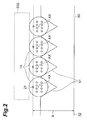
- Fig. 2 shows the method for manufacturing the MCF connector in which the ends of the MCFs 1A are arranged in the array form on the installation face of the connector 50, and it is noted that a part of the configuration shown in this Fig.
- the rotational alignment step includes a method of carrying out the rotational alignment while monitoring the end faces of the MCFs 1A (cross section monitoring) and a method of carrying out the alignment while monitoring the side faces of the MCFs 1A (side face monitoring).
- Fig. 2 is a drawing to illustrate a step of attaching each of the MCFs 1A to the connector 50 provided with V-grooves 51 on the installation face opposed to a bottom face 52, as a method for one-dimensionally arranging the plurality of MCFs 1A.
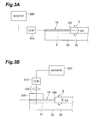
- Fig. 3A is a drawing showing a configuration of a monitor device for carrying out the cross section monitoring in the rotational alignment step.
- the monitor device shown in Fig. 3A is composed of a CCD camera 510 as an imaging device and a monitor 520 for displaying an image taken in by the CCD camera 510.
- the configuration around the connector 50 in Fig. 3A is coincident with the configuration shown in Fig. 2 ; that is, the ends of the MCFs 1A from which the resin coat 100 is removed in part are arranged on the respective V-grooves 51 of the connector 50.
- the plurality of V-shaped grooves 51 are formed in the array form on the surface (installation face) of the connector 50 and the ends of the MCFs 1A (the portions from which the resin coat 100 is removed) are mounted on the respective V-grooves 51 (arrangement step).
- the ends of the MCFs 1A thus mounted are pressed against the respective V-grooves 51 by a presser plate 500.
- the end faces of the MCFs 1A are cut approximately perpendicularly to the fiber axis AX and the end faces of the MCFs 1A each are monitored by the CCD camera 510.
- each MCF 1A is rotated on the V-groove 51 so as to maximize a distance A between the marker 21 and the bottom face 52 of the connector 50 (a height of the marker 21 with respect to the bottom face 52).
- each of the MCFs 1A is rotated around the fiber axis AX to implement such alignment that the markers 21 on the cross sections of the respective MCFs 1A are located at the same rotational position.
- the connector 50 does not have to be limited to the array using the V-grooves 51, but it may be one having holes for arrangement of the MCFs as many as the number of fibers (cf. Fig. 4B ).
- the arrangement of the MCFs in the connector does not have to be limited to one row, but it may be two or more rows.
- inter-fiber deviations of the outer diameters of the respective MCFs 1A are preferably smaller than 1 ⁇ m and core arrangement position errors, i.e., core position deviations from the fiber center are preferably such that an angle between the horizontal arrangement direction (the direction of the lines L1, L2) and a perpendicular thereto on which the marker 21 is provided (the line L3) is within the range not deviating more than 1° from 90°.
- the above method allows the core arrangement directions of the MCFs 1A to be aligned with a specific direction, by only checking the positions of the markers 21. For this reason, the adjustment of the core positions can be readily achieved. Since the adjustment is performed while monitoring each of the cut end faces of the MCFs (cross section monitoring), it is feasible to readily achieve the end face observation and core position adjustment. If the positions of the cut end faces of the respective MCFs deviate in the longitudinal direction (the direction along the fiber axis AX), it is considered that it becomes difficult to perform the monitoring with the CCD camera 510 and the core position adjustment with high accuracy because of the deviation from the focal position.
- Fig. 2 shows the example of the rotational alignment of each of the MCFs 1A to the position where the distance A between the marker 21 and the bottom face 52 of the connector 50 is maximum, but the rotational alignment can also be performed similarly with high accuracy by a method of rotating each of the MCFs 1A to a position where the distance A is minimum.
- the same effect is also achieved by making use of a connector to implement the fixing by a ferrule, instead of the connector provided with the V-grooves.
- the rotational alignment of the MCFs 1A arranged on the installation face of the connector 50 was carried out after the cutting of the ends, but the cutting of unnecessary ends may be carried out after completion of both of the rotational alignment step for each of the MCFs 1A and the fixing step between the MCFs 1 A and the connector.
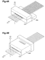
- the MCF connector shown in Fig. 4A has a connector 50A and a plurality of MCFs the ends of which are fixed to the connector 50A.
- the connector 50A has a support member in which a plurality of V-grooves are formed on its installation face, and a presser plate grasping the ends of the MCFs from which the resin coat is removed in part, in conjunction with the support member.
- the ends of the MCFs are simply grasped by the support member and the presser plate, the ends of the MCFs are kept each only projecting out from a connector end face 51A. Namely, each of the ends of the MCFs is held as rotatable by the support member and presser plate.
- the rotational alignment step is carried out while monitoring the ends of the MCFs projecting out from the connector end face 51A, from a direction of arrow P1 or from a direction of arrow P2.
- the monitoring of each of the ends of the MCFs from the arrow P1 direction corresponds to the cross section monitoring and the monitoring of each of the ends of the MCFs from the arrow P2 direction corresponds to the side face monitoring.
- the MCF connector shown in Fig. 4B has a connector 50B and a plurality of MCFs the ends of which are fixed to the connector 50B.
- the connector 50B has a plurality of holes to hold the ends of the MCFs from which the resin coat is removed in part, while the ends penetrate through the holes.
- the plurality of holes do not have to be limited to one row but may be formed in two or more rows.
- the ends of the MCFs merely penetrating through the holes of the connector 50B are kept each simply projecting out from a connector end face 51B. Namely, each of the ends of the MCFs is held as rotatable by the hole of the connector 50B.
- the rotational alignment step is carried out while monitoring the ends of the MCFs projecting out from the connector end face 51B, from the arrow P1 direction or from the arrow P2 direction.
- the monitoring of each of the ends of the MCFs from the arrow P1 direction corresponds to the cross section monitoring and the monitoring of each of the ends of the MCFs from the arrow P2 direction corresponds to the side face monitoring.
- the connector 50B and the ends of the MCFs after the rotational alignment each are bonded to be fixed (fixing step). Thereafter, the MCF connector is obtained through the cutting of portions exposed from the connector end face 51B out of the ends of the MCFs and through polishing of the connector end face 51B.
- FIG. 3B is a drawing showing the configuration of the monitor device for carrying out the side face monitoring in the rotational alignment step.
- the monitor device shown in Fig. 3B is comprised of the CCD camera 510 as an imaging device, and the monitor 520 for displaying an image taken in by the CCD camera 510 through an optical system 530 such as a microscope.
- the ends of the MCFs 1A from which the resin coat 100 is removed in part are arranged on the respective V-grooves 51 of the connector 50 and these MCFs 1A are pressed against the V-grooves 51 by a presser plate 500 made of a transparent material.
- a presser plate 500 made of a transparent material.
- the rotational position of each MCF is adjusted so that a distance between the marker 21 and a measuring device such as the microscope is constant, in attaching the MCF 1A to the V-groove 51 of the connector 50 or to the ferrule.
- a measuring device such as the microscope
- the rotational alignment is carried out while monitoring the marker 21 from the side face thereof.
- each of the core arrangement directions in the MCFs 1A is aligned with the specific direction.
- the rotational direction is adjusted so that distances between the marker 21 and adjacent cores become equal, whereby the arrangement directions of the MCFs can be aligned.
- the rotational alignment of the MCF 1A is carried out so that the distance S1 between the marker 21 and adjacent core 12 becomes equal to the distance S2 between the marker 21 and core 13.
- the rotational alignment step is to perform the rotational alignment for each of the MCFs 1A while monitoring the marker 21 and cores around it (the cores 12, 13 herein) from the side face thereof.
- the present embodiment allows the rotational alignment to be implemented so as to adjust each of the MCFs 1A to the same rotational position. The reason for it is that even if the outer diameter of MCF varies along the longitudinal direction, there is no change in relative positions and in angular relationship between the cores and marker (without being affected by the variation in outer diameter along the longitudinal direction).
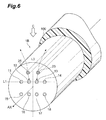
- Fig. 6 is a cross-sectional view of MCF 1B according to the second embodiment.
- Fig. 6 shows a cross section perpendicular to the fiber axis AX, of the MCF 1B.
- the MCF 1B of the second embodiment is different in the following point from the MCF 1A. Namely, the different point is that there are two markers 22, 23 provided.
- the marker 22 in the MCF 1B is provided at a position where the marker 22 is superimposed on the core 12, when the side face of the MCF 1B is viewed from a direction of arrow C in Fig. 6 .
- the marker 23 in the MCF 1B is provided at a position (fourth position) where the marker 23 is superimposed on the core 13, when the side face of the MCF 1B is viewed from the direction of arrow C in Fig. 6 .
- the rotational alignment step for a plurality of MCFs 1B having this structure is carried out by the same methods as the methods shown in Fig. 2 .
- each MCF 1B is rotated so as to maximize the distance A of one marker out of the markers 22, 23 from the connector bottom face (the height of the marker with respect to the connector bottom face) in the same manner as in the first embodiment. It results in aligning each of the plurality of MCFs 1B to the same rotational position and thus suitably aligning the core arrangement directions in the MCFs 1B.
- the rotational alignment may be performed for each of the MCFs 1B so as to minimize the distance A.
- the MCF 1B may be rotated so as to make the markers 22, 23 horizontal when the end face of the MCF 1B is viewed.
- the rotational alignment of the MCFs 1B can be performed with accuracy.
- each MCF 1B may be rotated so that both of the markers 22, 23 of the MCF 1B are superimposed on the cores 12, 13 when the side face of the MCF 1B is viewed from a predetermined direction (the direction of arrow C).
- the rotational alignment of the MCFs 1B can be performed with accuracy.
- the alignment can be carried out by the following method in the rotational alignment step. Namely, as shown in Fig. 7 , the alignment is performed so that distances between each of the two markers 22, 23 and a line coincident with the fiber axis AX of the MCF 1B (a straight line L4 in Fig. 7 , which will be referred to hereinafter as "fiber axis line") become equal.
- the markers 22, 23 are preferably located at positions symmetric with respect to a straight line passing the cross-sectional center (fiber axis line) and being perpendicular to the line L1 (which corresponds to the line L3 in Fig. 6 ). It is noted, however, that, without having this configuration, the rotational alignment of MCF can also be performed based on the positional relationship between the two markers and the fiber axis line.
- Fig. 8 is a cross-sectional view of MCF 1C according to the third embodiment.
- Fig. 8 shows a cross section perpendicular to the fiber axis AX.
- the MCF 1C of the third embodiment is different in the following point from the MCF 1A. Namely, the different point is that the fiber is provided with two markers 24,25 and a reference marker 26.
- the markers 24, 25 are preferably provided at positions symmetric with respect to a straight line L3 passing the cross-sectional center (bordered position in the cross section intersecting with the fiber axis AX) and being perpendicular to the line L1.
- the reference marker 26 is provided on the straight line L3.
- the reference marker 26 is disposed at the center of the MCF 1C, but it may be located below the cores 15-18 in the drawing or may be located outside the markers 24, 25.
- the rotational alignment step for a plurality of MCFs 1C having this structure is also carried out by the same methods as the methods shown in Fig. 2 .
- each MCF 1C is rotated so as to maximize the distance A of one marker out of the markers 24, 25 from the connector bottom face in the same manner as in the second embodiment. It results in aligning each of the plurality of MCFs 1C to the same rotational position and thus suitably aligning the core arrangement directions in the MCFs 1C.
- the rotational alignment may be performed for each of the MCFs 1C so as to minimize the distance A.
- the MCF 1C may be rotated so as to make the markers 24, 25 horizontal when the end face of the MCF 1C is viewed.
- the rotational alignment of the MCFs 1C can be performed with accuracy.
- the MCF 1C when the alignment of each MCF 1C is performed while monitoring the side face, the MCF 1C may be rotated so that the reference marker 26 is located at a midpoint between the markers 24, 25 of the MCF 1C when the side face of the MCF 1C is viewed from a predetermined direction (the direction of arrow D).
- the rotational alignment of MCFs 1C can be performed with accuracy.
- the core arrangement directions of the plurality of the MCFs 1C can be suitably aligned.
- Fig. 9 is a cross-sectional view of MCF 1D according to the fourth embodiment.
- Fig. 9 shows a cross section perpendicular to the fiber axis AX, of the MCF 1D.
- the MCF 1D of the fourth embodiment is different in the following point from the MCF 1A. Namely, the different point is that a reference marker 27 is provided on the line L3, in addition to the marker 21.
- the reference marker 27 in the MCF 1D is provided on the line L3.
- the reference marker 27 is disposed at the cross-sectional center of the MCF 1D, but it may be located below the cores 15-18 in the drawing or may be located outside the markers 24, 25.
- the rotational alignment step for a plurality of MCFs 1D having this structure is also carried out by the same methods as the methods shown in Fig. 2 .
- each MCF 1D is rotated so as to maximize the distance A between the marker 21 and the connector bottom face in the same manner as in the first embodiment. It results in aligning each of the plurality of MCFs 1D to the same rotational position and thus suitably aligning the core arrangement directions in the MCFs 1D.
- the rotational alignment may be performed for each of the MCFs 1D so as to minimize the distance A.
- each MCF 1D when the alignment of the MCF 1D is performed while monitoring the side face, the MCF 1D may be rotated so that the marker 21 and the reference marker 27 of the MCF 1D are superimposed when the side face of the MCF 1D is viewed from a predetermined direction.
- the rotational alignment of each MCF 1D can be performed with accuracy.
- the plurality of MCFs 1C each rotated in this manner are arranged on the installation surface of the connector, the rotational alignment of each MCF 1C can be performed with accuracy.
- the alignment is performed while monitoring the side face as described above, there is a constant geometric position relationship maintained among the cores, marker, and reference marker, even with variation in fiber outer diameter; therefore, the alignment can be performed with higher accuracy for the MCFs 1D.
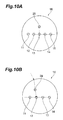
- one marker 28 is provided for the cores 11-14 (or 11-15) each arranged on the line L1.
- the marker 28 is provided on a straight line L5 passing the center core 13 out of the five aligned cores 11-15. This core 13 is disposed at the center of the MCF 1E.
- the marker 28 is disposed at a position where the marker 28 is superimposed on the core 12.
- the rotational alignment of the MCF 1E can be performed while monitoring the cross section by the aforementioned method.
- the rotational alignment of the MCF 1E can be performed by rotating the fiber so as to make the marker 28 superimposed on the specific core, while monitoring the side face.
- the position of the marker can be changed as occasion demands. It is noted that the arrangements of the markers in the respective embodiments described above may be used in combination.
- the connector may be configured as an array type connector of the structure in which the core arrangement directions of the MCFs are aligned with a specific direction and in which the MCFs are pressed from top by the presser plate 500.
- the above embodiments showed the examples of the connectors with the MCFs arranged therein (fiber arrangement section) in which the through holes or V-grooves were one-dimensionally (linearly) arranged, but the connector may be configured with a plurality of rows of linear through holes or V-grooves are present in parallel.
- the cross-sectional shape of the MCFs does not have to be limited to the circular shape, but the MCFs to be used may be, for example, those of a D-type cross-sectional shape with a linear part formed by removing a part of the outer periphery.
- the MCFs of the D-type cross-sectional shape when the linear part is made coincident with the core arrangement direction, it functions to align the arrangement directions in the MCFs. It is based on the premise that the removed face (linear part) is aligned with the arrangement direction and the shape of the linear part is maintained.
- rotation of each MCF can also be suitably implemented by providing the connector where the MCFs are arranged (fiber arrangement section), with the array of normal circular holes or V-grooves.
- the splice loss is preferably not more than 0.5 dB.
- the cladding diameter fiber diameter
- the MCFs were those having the core arrangement shown in Fig. 1 .
- Fig. 11 graph G1210 shows the relationship between deviation of rotational angle and splice loss in the outer cores and graph G1220 the relationship between deviation of rotational angle and splice loss in the inner cores.
- the outer cores refer to the cores 11, 14, 15, and 18 being the cores located outside, and the inner cores refer to the cores 12, 13, 16, and 17 located on the center side.
- the deviation of rotational angle is preferably kept not more than 1° and the deviation of rotational angle is more preferably not more than 0.5°. Since the MCF and the method for manufacturing the MCF connector according to the embodiment of the invention allow the adjustment of rotational position to be implemented with accuracy, the splice loss in splicing between MCFs can be kept not more than 0.5 dB.
Landscapes
- Physics & Mathematics (AREA)
- General Physics & Mathematics (AREA)
- Optics & Photonics (AREA)
- Mechanical Coupling Of Light Guides (AREA)
- Optical Fibers, Optical Fiber Cores, And Optical Fiber Bundles (AREA)
- Optical Couplings Of Light Guides (AREA)
Abstract
Description
- The present invention relates to a multi-core optical fiber (hereinafter referred to as "MCF") and a method for manufacturing a multi-core optical fiber connector (hereinafter referred to as "MCF connector").
- An MCF is comprised of a plurality of cores extending along a fiber axis direction (which is a direction coinciding with the longitudinal direction of the MCF and extending along the fiber axis passing a center of a cross section of the MCF perpendicular to the longitudinal direction), and a common cladding covering each of these cores. Each of the cores optically functions as an optical waveguide. Since the MCF has a larger number of cores per unit cross-sectional area than a single-core fiber does, it is suitable for transmission of large volumes of information.
- As a method for fusion splice between two MCFs,
Patent Literature 1 discloses an example of implementing optical axis alignment between the MCFs by making use of marker portions provided in the respective MCFs. Specifically, in a fusion splice operation, first, while monitoring the side faces of the two MCFs as splicing objects, each of the MCFs is rotated around the fiber axis and the two MCFs are checked as to positions after rotation (hereinafter referred to as "rotational positions") of the cores and marker portion varying with the rotation. When agreement is confirmed between monitor patterns of the two MCFs (or between arrangements each consisting of the cores and marker portion in the MCFs, which are displayed on a monitor screen during monitoring their side faces), an alignment work is carried out by horizontally/vertically moving the core positions while keeping the end faces of the two MCFs facing each other. After the alignment, the end faces of the two MCFs as splicing objects are subjected to fusion splice. - Patent Literature 1: Japanese Patent Application Laid-open Publication No.
2013-50695 - The Inventors conducted research on the conventional MCFs and others and found the problem as described below. Specifically, the splice method described in the
above Patent Literature 1 is carried out with comparison between the monitor patterns of the two MCFs, and it is considered that the positions of the cores in each MCF can be unspecified positions. For enabling the monitoring of the side faces, it was necessary to locate the marker at a position off an arbitrary line-symmetric axis to define line symmetry of the core arrangement in the cross section of the MCF. In the case of a connector component such as an array in which rotational positions of a plurality of MCFs one-dimensionally arranged each are aligned, splicing objects of these MCFs are not determined. In manufacturing a component in which, by making use of a plurality of MCFs each having core arrangement positions one-dimensionally arranged like the array, the arrangement directions of the cores (hereinafter referred to as "core arrangement directions") in these MCFs are aligned each with a specific direction, there was a need for a method allowing us to easily and accurately specify the core arrangement directions of the respective MCFs. - The present invention has been accomplished in order to solve the problem as described above, and it is an object of the present invention to provide an MCF with a structure allowing the core arrangement directions of one or more MCFs forming a connector component (e.g., an MCF connector) to be accurately aligned, and a method for manufacturing a connector component in which the core arrangement directions of one or more MCFs each are aligned.
-
- (1) An embodiment of the present invention relates to a method for manufacturing an MCF connector having one or more MCFs and a connector, and each of the MCFs comprises a plurality of cores, a marker, and a common cladding. The plurality of cores are arranged on a first straight line on a fiber cross section. In a cross section of each of the MCFs, the marker includes an element (first marker element) provided at a first position on a second straight line being perpendicular to the first straight line and passing a center of the cross section, or, elements (two second marker elements) provided at two second positions symmetric with respect to the second straight line. The method for manufacturing the MCF connector according to the embodiment of the invention comprises at least an arrangement step and a rotational alignment step. After the rotational alignment, the MCFs each rotationally aligned are fixed to the connector. In the arrangement step, each of the MCFs is arranged at a predetermined position of the connector. In the rotational alignment step, while monitoring the marker, each of the MCFs is rotated so that a rotational position of the marker comes to coincide with a specific position (by rotation around a fiber axis of the MCF (coincident with the longitudinal direction)). As each of the MCFs is rotationally aligned using the marker as an index, the core arrangement direction is aligned with a specific direction in each of the MCFs arranged in the connector.
- (2) The embodiment of the invention relates to a method for manufacturing an MCF connector having one or more MCFs and a connector, and each of the MCFs comprises a plurality of cores, a marker, and a common cladding. The plurality of cores are arranged on a first straight line on a fiber cross section. In a cross section of each of the MCFs, the marker is provided at a third position on a third straight line being perpendicular to the first straight line and passing a specific core included in the plurality of cores. The method for manufacturing the MCF connector according to the embodiment of the invention comprises at least an arrangement step and a rotational alignment step. After the rotational alignment, the MCFs each rotationally aligned may be fixed to the connector. In the arrangement step, each of the MCFs is arranged at a predetermined position of the connector. In the rotational alignment step, the marker is monitored in the cross section of each of the MCFs. While performing the cross section monitoring in this manner, each of the MCFs is rotated so that a rotational position of the marker comes to coincide with a specific position. Specifically, each of the MCFs is rotated so as to minimize each of a distance between the markers between adjacent MCFs, a distance between the specific cores between the adjacent MCFs, and a distance between the first straight lines between the adjacent MCFs. As a result, the core arrangement direction is aligned with a specific direction in each of the MCFs arranged in the connector. The distance between the first straight lines between the adjacent MCFs is defined as a center-to-center distance between a core in one MCF closest to the other MCF among the cores arranged on the first straight line in the one MCF and a core in the other MCF closest to the one MCF among the cores arranged on the first straight line in the other MCF.
- (3) The embodiment of the invention relates to a method for manufacturing an MCF connector having one or more MCFs and a connector, and each of the MCFs comprises a plurality of cores, a marker, and a common cladding. The plurality of cores are arranged on a first straight line on a fiber cross section. In each of the MCFs, the marker is provided at a fourth position on a view field where the marker is superimposed on a specific core included in the plurality of cores, when a side face of the MCF is monitored along a direction perpendicular to the first straight line. The method for manufacturing the MCF connector according to the embodiment of the invention comprises at least an arrangement step and a rotational alignment step. After the rotational alignment, the MCFs each rotationally aligned are fixed to the connector. In the arrangement step, each of the MCFs is arranged at a predetermined position of the connector. In the rotational alignment step, the marker is monitored from the side face of each of the MCFs. While performing such side face monitoring, each of the MCFs is rotated so that a rotational position of the marker comes to coincide with a specific position. Specifically, each of the MCFs is rotated so as to match positions on a monitor of the marker and the specific core with each other, on a monitor screen displaying the side faces of the respective MCFs, as monitored in the side face monitoring. As a result, the core arrangement direction is aligned with a specific direction in each of the MCFs arranged in the connector.
- (4) The embodiment of the invention relates to an MCF comprising a plurality of cores, a marker, and a common cladding individually surrounding these cores and marker. In a cross section of the MCF, the plurality of cores are arranged along a first straight line. In the cross section of the MCF, the marker includes a first marker element provided at a first position on a second straight line being perpendicular to the first straight line and passing a center of the cross section, or, second marker elements provided at two respective second positions symmetric with respect to the second straight line.
- (5) The embodiment of the invention relates to an MCF comprising a plurality of cores, a marker, and a common cladding individually surrounding these cores and marker. In a cross section of the MCF, the plurality of cores are arranged along a first straight line. In the cross section of the MCF, the marker is provided at a third position on a third straight line being perpendicular to the first straight line and passing a midpoint between two adjacent cores out of the plurality of cores.
- (6) The embodiment of the invention relates to an MCF comprising a plurality of cores, a marker, and a common cladding individually surrounding these cores and marker. In a cross section of the MCF, the plurality of cores are arranged along a first straight line. When a side face of the MCF is monitored along a direction perpendicular to the first straight line, the marker is provided at a fourth position on a view field where the marker is superimposed on a specific core included in the plurality of cores.
- The present invention has made it feasible to provide the MCF with the structure allowing the core arrangement directions of the MCFs held in the connector to be accurately aligned, and the method for manufacturing the MCF connector.
-
-
Fig. 1 is a cross-sectional view of the MCF according to the first embodiment. -
Fig. 2 is a drawing of a case where the MCFs of the first embodiment are arranged. -
Figs. 3A and 3B are drawings for illustrating various examples of the rotational alignment step. -
Figs. 4A and 4B are drawings for illustrating various examples of the method for manufacturing the MCF connector. -
Fig. 5 is a drawing of a case where the MCF of the first embodiment is monitored from the side face (monitor screen). -
Fig. 6 is a cross-sectional view of the MCF according to the second embodiment. -
Fig. 7 is a drawing of a case where the MCF of the second embodiment is monitored from the side face (monitor screen). -
Fig. 8 is a cross-sectional view of the MCF according to the third embodiment. -
Fig. 9 is a cross-sectional view of the MCF according to the fourth embodiment. -
Figs. 10A and 10B are cross-sectional views of the MCFs according to modification examples. -
Fig. 11 is a drawing of evaluation on correspondence relationship between deviation of rotational angle and splice loss. - First, aspects of the embodiment of the invention will be described as enumerated below.
- (1) A first aspect relates to a method for manufacturing an MCF connector and the MCF connector comprises one or more MCFs, and a connector having an installation face on which ends of the MCFs each are held, and a bottom face opposed to the installation face. The manufacturing method according to the first aspect comprises an arrangement step and a rotational alignment step. After the rotational alignment, the MCFs are bonded to be fixed to the connector (fixing step). In the arrangement step, each of the ends of the MCFs is arranged at a predetermined position on the installation face of the connector. In the rotational alignment step, each of the MCFs is rotated around a longitudinal direction of the MCF to adjust a rotational position of a cross section of each MCF, the cross section being perpendicular to the longitudinal direction. Each of the MCFs comprises a plurality of cores extending along the longitudinal direction, a marker extending along the longitudinal direction while being separated from each of the cores, and a common cladding individually surrounding the plurality of cores and the marker. In the cross section of each of the MCFs, a core arrangement consisting of the plurality of cores includes one or more linear arrangement elements and each of the linear arrangement elements is comprised of two or more cores arranged on a first straight line or on a straight line parallel to the first straight line. In the cross section of each of the MCFs, the marker includes at least one first marker element (at a first position) arranged on a second straight line being perpendicular to the first straight line and passing a center of the cross section, or, at least two second marker elements (at second positions) arranged in symmetry with respect to the second straight line. In the rotational alignment step, each of the MCFs is rotated around the longitudinal direction so as to locate the marker at a specific position, while monitoring the marker. By this rotational alignment, each of extending directions of the linear arrangement elements in the MCFs is aligned with a specific direction.
In the first aspect, as described above, each of the core arrangement directions in the MCFs is aligned with the specific direction, while monitoring the first marker element or the second marker elements. This facilitates positioning of the rotational direction around the longitudinal direction (fiber axis), for each of the MCFs. - (2) As a second aspect applicable to the above first aspect, the rotational alignment step may be configured to perform cross section monitoring to monitor each of the markers in the cross sections of the MCFs. In this cross section monitoring, when each of the markers of the MCFs includes the one first marker element and when a position of the one first marker element is represented by a height with respect to the bottom face of the connector, the rotational alignment step is carried out to rotationally align each of the MCFs around the longitudinal direction so that the one first marker element is located at a highest position for all of the MCFs or so that the one first marker element is located at a lowest position for all of the MCFs. On the other hand, in the cross section monitoring, when each of the markers of the MCFs includes the two second marker elements and when a position of each of the two second marker elements is represented by a height with respect to the bottom face of the connector, the rotational alignment step is carried out to rotationally align each of the MCFs around the longitudinal direction so that the two second marker elements are located at positions where an average of heights thereof is maximum for all of the MCFs, so that the two second marker elements are located at positions where the average of the heights thereof is minimum for all of the MCFs, or, so that the two second marker elements are located at positions where the heights thereof are equal for all of the MCFs. According to this second aspect, the rotational alignment is carried out while monitoring the cross section of each of the MCFs. In this case, since there is no influence made from variation in outer diameter or the like along the longitudinal direction, of each MCF, the rotational alignment of each MCF is facilitated.
- (3) As a third aspect applicable to the first or second aspect, the rotational alignment step may be configured to perform side face monitoring to monitor the marker from a side face of each of the MCFs. In this side face monitoring, when each of the markers of the MCFs includes the one first marker element, the rotational alignment step is carried out to rotationally align each of the MCFs around the longitudinal direction so that the one first marker element is coincident with a central axis (fiber axis) of the MCF including the first marker element for all of the MCFs. On the other hand, in the side face monitoring, when each of the markers of the MCFs includes the two second marker elements, the rotational alignment step is carried out to rotationally align each of the MCFs around the longitudinal direction so that the central axis (fiber axis) of the MCF including the two second marker elements is coincident with a midpoint of a line segment connecting centers of the two second marker elements for all of the MCFs, or, so that distances from each of the two second marker elements to the central axis (fiber axis) of the MCF including the two second marker elements are equal for all of the MCFs. According to this third aspect, the rotational alignment is carried out while monitoring the side face of each of the MCFs. In this case, since there is no influence made from variation in outer diameter or the like along the longitudinal direction, of each MCF, the rotational alignment of each MCF is facilitated.
- (4) As a fourth aspect applicable to at least any one of the above first to third aspects, each of the MCFs may further comprise a reference marker extending along the longitudinal direction and arranged at a position different from that of the marker, on the second straight line in the cross section. In this fourth aspect, the rotational alignment step is carried out to monitor each of the markers in side faces of the MCFs. In this side face monitoring, when each of the markers of the MCFs includes the one first marker element, the rotational alignment step is carried out to rotationally align each of the MCFs around the longitudinal direction so that the reference marker is coincident with the marker for all of the MCFs. On the other hand, when each of the markers of the MCFs includes the two second marker elements, the rotational alignment step is carried out to rotationally align each of the MCFs around the longitudinal direction so that the reference marker is coincident with a midpoint of a line segment connecting centers of the two second marker elements for all of the MCFs. By this fourth aspect, there is no influence made from variation in outer diameter or the like along the longitudinal direction, of each MCF, either, and thus the rotational alignment of each MCF is facilitated.
- (5) A fifth aspect relates to a method for manufacturing an MCF connector and the MCF connector comprises one or more MCFs; and a connector having an installation face where ends of the MCFs each are held and a bottom face opposed to the installation face. The manufacturing method according to the first aspect comprises an arrangement step and a rotational alignment step. After the rotational alignment, the MCFs are bonded to be fixed to the connector (fixing step). In the arrangement step, each of the ends of the MCFs is arranged at a predetermined position on the installation face of the connector. In the rotational alignment step, each of the MCFs is rotated around a longitudinal direction of the MCF to adjust a rotational position of the cross section of the MCF, the cross section being perpendicular to the longitudinal direction. Each of the MCFs comprises a plurality of cores extending along the longitudinal direction, a marker extending along the longitudinal direction while being separated from each of the cores, and a common cladding individually surrounding the plurality of cores and the marker. In a cross section of each of the MCFs, a core arrangement consisting of the plurality of cores includes one or more linear arrangement elements and each of the linear arrangement elements is comprised of two or more cores arranged on a first straight line or on a straight line parallel to the first straight line. In the cross section of each of the MCFs, the marker is arranged on a second straight line being perpendicular to the first straight line and passing a specific core out of the plurality of cores. In other words, the marker is arranged at a third position on a third straight line perpendicular to the first straight line and passing the specific core out of the plurality of cores. In the rotational alignment step, each of the MCFs is rotated around the longitudinal direction so as to locate the marker at a specific position, while monitoring the marker in the cross section. Specifically, each of the MCFs is rotationally aligned so as to minimize each of a distance between the markers in adjacent MCFs out of the MCFs arranged on the installation face, a distance between the specific cores in the adjacent MCFs, and a distance between the linear arrangement elements in the adjacent MCFs (distance between the first straight lines). By this rotational alignment, each of extending directions of the linear arrangement elements in the MCFs is aligned with a specific direction.
- (6) A sixth aspect relates to a method for manufacturing an MCF connector and the MCF connector comprises one or more MCFs; and a connector having an installation face where ends of the MCFs each are held and a bottom face opposed to the installation face. The manufacturing method according to the first aspect comprises an arrangement step and a rotational alignment step. After the rotational alignment, the MCFs are bonded to be fixed to the connector (fixing step). In the arrangement step, each of the ends of the MCFs is arranged at a predetermined position on the installation face of the connector. In the rotational alignment step, each of the MCFs is rotated around a longitudinal direction of the MCF to adjust a rotational position of the cross section of each MCF, the cross section being perpendicular to the longitudinal direction. Each of the MCFs comprises a plurality of cores extending along the longitudinal direction, a marker extending along the longitudinal direction while being separated from each of the cores, and a common cladding individually surrounding the plurality of cores and the marker. In a cross section of each of the MCFs, a core arrangement consisting of the plurality of cores includes one or more linear arrangement elements and each of the linear arrangement elements is comprised of two or more cores arranged on a first straight line or on a straight line parallel to the first straight line. In the cross section of each of the MCFs, the marker is arranged on a second straight line being perpendicular to the first straight line and passing a specific core out of the plurality of cores. In other words, the marker is arranged at a third position on a third straight line perpendicular to the first straight line and passing the specific core out of the plurality of cores. When each of the side faces of the MCFs is monitored along the line perpendicular to the first straight line, the marker is arranged at a position (fourth position) where the marker is superimposed on the specific core included in the plurality of cores, in each of the MCFs. In this side face monitoring, the rotational alignment step is carried out to rotate each of the MCFs around the longitudinal direction so as to make the marker and the specific core superimposed (preferably, so as to make them coincident with each other), while monitoring the marker and the specific core from the side face. The positional relationship between the marker and the specific core can be confirmed on a monitor screen. By this rotational alignment, each of extending directions of the linear arrangement elements in the MCFs is aligned with a specific direction.
- (7) As a seventh aspect applicable to the sixth aspect, preferably, a maximum width of the marker as monitored from the side face is not more than a maximum width of the specific core, in each of the MCFs. In this case, visibility of the marker is improved and thus alignment accuracy can be improved. As an aspect applicable to at least any one of the first to seventh aspects, each of the MCFs preferably comprises a resin coat provided on an outer peripheral surface of the cladding. In the manufacturing methods according to the first to seventh aspects, the ends of the MCFs, from which the resin coat is removed in part, are arranged each on the installation face of the corrector.
The MCF according to the embodiment of the invention is one to which any one of eighth to tenth aspects as described below is applied. - (8) An MCF according to the eighth aspect comprises: a plurality of cores extending along a longitudinal direction of the MCF; a marker extending along the longitudinal direction while being separated from each of the plurality of cores; and a common cladding individually surrounding the plurality of cores and the marker. In a cross section of the MCF perpendicular to the longitudinal direction, a core arrangement consisting of the plurality of cores includes one or more linear arrangement elements and each of the linear arrangement elements is comprised of two or more cores arranged on a first straight line or on a straight line parallel to the first straight line. In the cross section of the multi-core optical fiber, the marker includes at least one first marker element (at a first position) arranged on a second straight line being perpendicular to the first straight line and passing a center of the cross section, or, at least two second marker elements (at second positions) arranged in symmetry with respect to the second straight line.
- (9) An MCF according to the ninth aspect comprises: a plurality of cores extending along a longitudinal direction of the MCF; a marker extending along the longitudinal direction while being separated from each of the plurality of cores; and a common cladding individually surrounding the plurality of cores and the marker. In a cross section of the MCF perpendicular to the longitudinal direction, a core arrangement consisting of the plurality of cores includes one or more linear arrangement elements and each of the linear arrangement elements is comprised of two or more cores arranged on a first straight line or on a straight line parallel to the first straight line. In the cross section of the MCF, the marker is arranged on a second straight line being perpendicular to the first straight line and passing a midpoint between two adjacent cores out of the cores belonging to one of the linear arrangement elements. In other words, the marker is arranged at a third position on a third straight line being perpendicular to the first straight line and passing the midpoint between the two adjacent cores out of the cores belonging to one of the linear arrangement elements.
- (10) An MCF according to the tenth aspect comprises: a plurality of cores extending along a longitudinal direction of the MCF; a marker extending along the longitudinal direction while being separated from each of the plurality of cores; and a common cladding individually surrounding the plurality of cores and the marker. In a cross section of the MCF perpendicular to the longitudinal direction, a core arrangement consisting of the plurality of cores includes one or more linear arrangement elements and each of the linear arrangement elements is comprised of two or more cores arranged on a first straight line or on a straight line parallel to the first straight line. When a side face of the MCF is monitored along a direction perpendicular to the first straight line, the marker is arranged at a position where the marker is superimposed on a specific core included in the plurality of cores (fourth position).
- Specific examples of the MCF (multi-core optical fiber) and the method for manufacturing the MCF connector (multi-core optical fiber connector) according to the embodiment of the invention will be described below in detail with reference to the accompanying drawings. It should be noted that the present invention is by no means intended to be limited to these examples presented by way of illustration but is intended for inclusion of all changes within the meaning and scope of equivalency to the scope of claims, as described in the scope of claims.
-
Fig. 1 is a cross-sectional view ofMCF 1A according to the first embodiment.Fig. 1 shows a cross section perpendicular to the fiber axis AX (coincident with the longitudinal direction of the MCF). TheMCF 1A of the first embodiment has eightcores 11 to 18 each extending along the fiber axis AX, amarker 21 extending along the fiber axis AX, acommon cladding 30 individually surrounding these cores 11-18 andmarker 21, and aresin coat 100 provided on the outer peripheral surface of thecladding 30. The cores 11-18 andmarker 21 extend along the fiber axis AX. The refractive index of each of the cores 11-18 is higher than that of thecladding 30. The refractive index of themarker 21 is different from that of thecladding 30. InFig. 1 , the cross-sectional shape of each of the cores 11-18 andmarker 21 is a circle but there are no particular restrictions on the cross-sectional shapes of these. The number of cores does not have to be limited to 8, but may be 9 or more, or, 6 or less. Theresin coat 100 may be comprised of a plurality of resin layers. - Each of the cores 11-18,
marker 21, andcladding 30 consists primarily of silica glass and is doped with an impurity for adjustment of refractive index as needed. For example, each of the cores 11-18 andmarker 21 is made of silica glass doped with GeO2, while thecladding 30 is made of pure silica glass. Or, for example, each of the cores 11-18 andmarker 21 is made of pure silica glass, while thecladding 30 is made of silica glass doped with the element F. The core diameters of the respective cores 11-18 may be equal or unequal. The refractive indices of the respective cores 11-18 may be equal or unequal. - In a cross section perpendicular to the fiber axis AX, of the
MCF 1A shown inFig. 1 , thecores 11 to 14 are arranged at equal intervals along a straight line L1 not passing the center of theMCF 1A. These cores 11-14 constitute first linear arrangement elements. Thecores 15 to 18 are arranged at equal intervals along a straight line L2 not passing the cross-sectional center of theMCF 1A (a position on the cross section intersecting with the fiber axis AX). These cores 15-18 constitute second linear arrangement elements. The straight line L1 and line L2 are parallel to each other. The intervals of the cores 11-14 and the intervals of the cores 15-18 are properly adjusted so as not to generate crosstalk between them and, each set of thecores cores MCF 1A and being perpendicular to the line L1 (L2). Similarly, each set of thecores cores marker 21 is arranged at a position (first position) outside the line L1 in the fiber and on the line L3. The number of straight lines for arrangement of the cores does not have to be limited to 2 but may be one or three or more. - The following will describe a method for manufacturing an MCF connector in which the
MCFs 1A shown inFig. 1 are arranged in an array form on an installation face ofconnector 50. As shown inFig. 2 , the manufacturing method includes an arrangement step and a rotational alignment step in an operation of arranging the plurality ofMCFs 1A in the array form and, after the rotational alignment, each of theMCFs 1A is bonded to be fixed to the installation face of the connector 50 (fixing step).Fig. 2 shows the method for manufacturing the MCF connector in which the ends of theMCFs 1A are arranged in the array form on the installation face of theconnector 50, and it is noted that a part of the configuration shown in thisFig. 2 corresponds to a configuration wherein only oneMCF 1A is installed on the installation face of theconnector 50. Examples of the rotational alignment step include a method of carrying out the rotational alignment while monitoring the end faces of theMCFs 1A (cross section monitoring) and a method of carrying out the alignment while monitoring the side faces of theMCFs 1A (side face monitoring). - First described is the method of carrying out the rotational alignment of each of the
MCFs 1A while monitoring the end face of each of theMCFs 1A.Fig. 2 is a drawing to illustrate a step of attaching each of theMCFs 1A to theconnector 50 provided with V-grooves 51 on the installation face opposed to abottom face 52, as a method for one-dimensionally arranging the plurality ofMCFs 1A.Fig. 3A is a drawing showing a configuration of a monitor device for carrying out the cross section monitoring in the rotational alignment step. The monitor device shown inFig. 3A is composed of aCCD camera 510 as an imaging device and amonitor 520 for displaying an image taken in by theCCD camera 510. The configuration around theconnector 50 inFig. 3A is coincident with the configuration shown inFig. 2 ; that is, the ends of theMCFs 1A from which theresin coat 100 is removed in part are arranged on the respective V-grooves 51 of theconnector 50. - As shown in
Fig. 2 , the plurality of V-shapedgrooves 51 are formed in the array form on the surface (installation face) of theconnector 50 and the ends of theMCFs 1A (the portions from which theresin coat 100 is removed) are mounted on the respective V-grooves 51 (arrangement step). Here, the ends of theMCFs 1A thus mounted are pressed against the respective V-grooves 51 by apresser plate 500. The end faces of theMCFs 1A are cut approximately perpendicularly to the fiber axis AX and the end faces of theMCFs 1A each are monitored by theCCD camera 510. While checking the position of themarker 21 in the cross section displayed on the screen of the monitor 520 (monitor screen), the rotational position of eachMCF 1A is adjusted (rotational alignment step). Here, eachMCF 1A is rotated on the V-groove 51 so as to maximize a distance A between themarker 21 and thebottom face 52 of the connector 50 (a height of themarker 21 with respect to the bottom face 52). Specifically, each of theMCFs 1A is rotated around the fiber axis AX to implement such alignment that themarkers 21 on the cross sections of therespective MCFs 1A are located at the same rotational position. Theconnector 50 does not have to be limited to the array using the V-grooves 51, but it may be one having holes for arrangement of the MCFs as many as the number of fibers (cf.Fig. 4B ). The arrangement of the MCFs in the connector (the linear arrangement) does not have to be limited to one row, but it may be two or more rows. - In this regard, inter-fiber deviations of the outer diameters of the
respective MCFs 1A are preferably smaller than 1 µm and core arrangement position errors, i.e., core position deviations from the fiber center are preferably such that an angle between the horizontal arrangement direction (the direction of the lines L1, L2) and a perpendicular thereto on which themarker 21 is provided (the line L3) is within the range not deviating more than 1° from 90°. - The above method allows the core arrangement directions of the
MCFs 1A to be aligned with a specific direction, by only checking the positions of themarkers 21. For this reason, the adjustment of the core positions can be readily achieved. Since the adjustment is performed while monitoring each of the cut end faces of the MCFs (cross section monitoring), it is feasible to readily achieve the end face observation and core position adjustment. If the positions of the cut end faces of the respective MCFs deviate in the longitudinal direction (the direction along the fiber axis AX), it is considered that it becomes difficult to perform the monitoring with theCCD camera 510 and the core position adjustment with high accuracy because of the deviation from the focal position. -
Fig. 2 shows the example of the rotational alignment of each of theMCFs 1A to the position where the distance A between themarker 21 and thebottom face 52 of theconnector 50 is maximum, but the rotational alignment can also be performed similarly with high accuracy by a method of rotating each of theMCFs 1A to a position where the distance A is minimum. The same effect is also achieved by making use of a connector to implement the fixing by a ferrule, instead of the connector provided with the V-grooves. - In the above-described example, the rotational alignment of the
MCFs 1A arranged on the installation face of theconnector 50 was carried out after the cutting of the ends, but the cutting of unnecessary ends may be carried out after completion of both of the rotational alignment step for each of theMCFs 1A and the fixing step between theMCFs 1 A and the connector. - For example, the MCF connector shown in
Fig. 4A has a connector 50A and a plurality of MCFs the ends of which are fixed to the connector 50A. The connector 50A has a support member in which a plurality of V-grooves are formed on its installation face, and a presser plate grasping the ends of the MCFs from which the resin coat is removed in part, in conjunction with the support member. In a state in which the ends of the MCFs are simply grasped by the support member and the presser plate, the ends of the MCFs are kept each only projecting out from aconnector end face 51A. Namely, each of the ends of the MCFs is held as rotatable by the support member and presser plate. The rotational alignment step is carried out while monitoring the ends of the MCFs projecting out from the connector end face 51A, from a direction of arrow P1 or from a direction of arrow P2. The monitoring of each of the ends of the MCFs from the arrow P1 direction corresponds to the cross section monitoring and the monitoring of each of the ends of the MCFs from the arrow P2 direction corresponds to the side face monitoring. After completion of the rotational alignment step, the support member, the presser plate, and the ends of the MCFs after the rotational alignment each are bonded to be fixed (fixing step). Thereafter, the MCF connector is obtained through the cutting of portions exposed from theconnector end face 51A out of the ends of the MCFs and through polishing of theconnector end face 51A. - The MCF connector shown in
Fig. 4B has aconnector 50B and a plurality of MCFs the ends of which are fixed to theconnector 50B. Theconnector 50B has a plurality of holes to hold the ends of the MCFs from which the resin coat is removed in part, while the ends penetrate through the holes. The plurality of holes do not have to be limited to one row but may be formed in two or more rows. The ends of the MCFs merely penetrating through the holes of theconnector 50B are kept each simply projecting out from aconnector end face 51B. Namely, each of the ends of the MCFs is held as rotatable by the hole of theconnector 50B. The rotational alignment step is carried out while monitoring the ends of the MCFs projecting out from theconnector end face 51B, from the arrow P1 direction or from the arrow P2 direction. The monitoring of each of the ends of the MCFs from the arrow P1 direction corresponds to the cross section monitoring and the monitoring of each of the ends of the MCFs from the arrow P2 direction corresponds to the side face monitoring. After completion of the rotational alignment step, theconnector 50B and the ends of the MCFs after the rotational alignment each are bonded to be fixed (fixing step). Thereafter, the MCF connector is obtained through the cutting of portions exposed from theconnector end face 51B out of the ends of the MCFs and through polishing of theconnector end face 51B. - Next, the below will describe the case where the rotational alignment of each
MCF 1A is carried out while monitoring each of the side faces of theMCFs 1A (side face monitoring).Fig. 3B is a drawing showing the configuration of the monitor device for carrying out the side face monitoring in the rotational alignment step. The monitor device shown inFig. 3B is comprised of theCCD camera 510 as an imaging device, and themonitor 520 for displaying an image taken in by theCCD camera 510 through anoptical system 530 such as a microscope. The ends of theMCFs 1A from which theresin coat 100 is removed in part are arranged on the respective V-grooves 51 of theconnector 50 and theseMCFs 1A are pressed against the V-grooves 51 by apresser plate 500 made of a transparent material. There is no light source illustrated in the monitor devices shown inFigs. 3A and 3B , but these monitor devices may be equipped with a light source if a sufficient quantity of light cannot be secured in the monitoring. - Specifically, when each of the side faces of the
MCFs 1A is monitored, the rotational position of each MCF is adjusted so that a distance between themarker 21 and a measuring device such as the microscope is constant, in attaching theMCF 1A to the V-groove 51 of theconnector 50 or to the ferrule. For attaching theMCFs 1A to the V-grooves 51 of theconnector 50, we can adopt such a means as mounting theMCFs 1A on the V-grooves and thereafter pressing theMCFs 1A against the V-grooves 51 from top by thetransparent presser plate 500. - For each of the
MCFs 1A mounted on the V-grooves 51 of theconnector 50, the rotational alignment is carried out while monitoring themarker 21 from the side face thereof. Through this rotational alignment step, each of the core arrangement directions in theMCFs 1A is aligned with the specific direction. At this time, the rotational direction is adjusted so that distances between themarker 21 and adjacent cores become equal, whereby the arrangement directions of the MCFs can be aligned. Specifically, while viewing the side face of theMCF 1A from a direction of arrow B inFig. 5 , the rotational alignment of theMCF 1A is carried out so that the distance S1 between themarker 21 andadjacent core 12 becomes equal to the distance S2 between themarker 21 andcore 13. - As described above, the rotational alignment step is to perform the rotational alignment for each of the
MCFs 1A while monitoring themarker 21 and cores around it (thecores marker 21 but also the neighboring cores, but the present embodiment allows the rotational alignment to be implemented so as to adjust each of theMCFs 1A to the same rotational position. The reason for it is that even if the outer diameter of MCF varies along the longitudinal direction, there is no change in relative positions and in angular relationship between the cores and marker (without being affected by the variation in outer diameter along the longitudinal direction). -
Fig. 6 is a cross-sectional view ofMCF 1B according to the second embodiment.Fig. 6 shows a cross section perpendicular to the fiber axis AX, of theMCF 1B. TheMCF 1B of the second embodiment is different in the following point from theMCF 1A. Namely, the different point is that there are twomarkers - The
marker 22 in theMCF 1B is provided at a position where themarker 22 is superimposed on thecore 12, when the side face of theMCF 1B is viewed from a direction of arrow C inFig. 6 . Similarly, themarker 23 in theMCF 1B is provided at a position (fourth position) where themarker 23 is superimposed on thecore 13, when the side face of theMCF 1B is viewed from the direction of arrow C inFig. 6 . - The rotational alignment step for a plurality of
MCFs 1B having this structure is carried out by the same methods as the methods shown inFig. 2 . For example, when the alignment is carried out while monitoring the end face, eachMCF 1B is rotated so as to maximize the distance A of one marker out of themarkers MCFs 1B to the same rotational position and thus suitably aligning the core arrangement directions in theMCFs 1B. The rotational alignment may be performed for each of theMCFs 1B so as to minimize the distance A. - Referring to each
MCF 1B, theMCF 1B may be rotated so as to make themarkers MCF 1B is viewed. By arranging each of theMCFs 1B rotated in this manner on the installation face of the connector, the rotational alignment of theMCFs 1B can be performed with accuracy. - For example, when the alignment is performed while monitoring the side face, each
MCF 1B may be rotated so that both of themarkers MCF 1B are superimposed on thecores MCF 1B is viewed from a predetermined direction (the direction of arrow C). By arranging each of theMCFs 1B rotated in this manner on the installation face of the connector, the rotational alignment of theMCFs 1B can be performed with accuracy. - Furthermore, when the fiber is provided with two markers, the alignment can be carried out by the following method in the rotational alignment step. Namely, as shown in
Fig. 7 , the alignment is performed so that distances between each of the twomarkers MCF 1B (a straight line L4 inFig. 7 , which will be referred to hereinafter as "fiber axis line") become equal. When the alignment is performed in this manner, themarkers Fig. 6 ). It is noted, however, that, without having this configuration, the rotational alignment of MCF can also be performed based on the positional relationship between the two markers and the fiber axis line. -
Fig. 8 is a cross-sectional view ofMCF 1C according to the third embodiment.Fig. 8 shows a cross section perpendicular to the fiber axis AX. TheMCF 1C of the third embodiment is different in the following point from theMCF 1A. Namely, the different point is that the fiber is provided with twomarkers reference marker 26. - The
markers reference marker 26 is provided on the straight line L3. In theMCF 1C according to the present embodiment, thereference marker 26 is disposed at the center of theMCF 1C, but it may be located below the cores 15-18 in the drawing or may be located outside themarkers - The rotational alignment step for a plurality of
MCFs 1C having this structure is also carried out by the same methods as the methods shown inFig. 2 . For example, when the alignment is carried out while monitoring the end face, eachMCF 1C is rotated so as to maximize the distance A of one marker out of themarkers MCFs 1C to the same rotational position and thus suitably aligning the core arrangement directions in theMCFs 1C. The rotational alignment may be performed for each of theMCFs 1C so as to minimize the distance A. - Referring to each
MCF 1C, theMCF 1C may be rotated so as to make themarkers MCF 1C is viewed. By arranging each of theMCFs 1C rotated in this manner on the installation face of the connector, the rotational alignment of theMCFs 1C can be performed with accuracy. - For example, when the alignment of each
MCF 1C is performed while monitoring the side face, theMCF 1C may be rotated so that thereference marker 26 is located at a midpoint between themarkers MCF 1C when the side face of theMCF 1C is viewed from a predetermined direction (the direction of arrow D). By arranging each of theMCFs 1C rotated in this manner on the installation face of the connector, the rotational alignment ofMCFs 1C can be performed with accuracy. In the case where the plurality ofMCFs 1C are arranged on the installation surface of the connector, the core arrangement directions of the plurality of theMCFs 1C can be suitably aligned. -
Fig. 9 is a cross-sectional view ofMCF 1D according to the fourth embodiment.Fig. 9 shows a cross section perpendicular to the fiber axis AX, of theMCF 1D. TheMCF 1D of the fourth embodiment is different in the following point from theMCF 1A. Namely, the different point is that areference marker 27 is provided on the line L3, in addition to themarker 21. - The
reference marker 27 in theMCF 1D is provided on the line L3. In theMCF 1D according to the present embodiment, thereference marker 27 is disposed at the cross-sectional center of theMCF 1D, but it may be located below the cores 15-18 in the drawing or may be located outside themarkers - The rotational alignment step for a plurality of
MCFs 1D having this structure is also carried out by the same methods as the methods shown inFig. 2 . For example, when the alignment is carried out while monitoring the end face, eachMCF 1D is rotated so as to maximize the distance A between themarker 21 and the connector bottom face in the same manner as in the first embodiment. It results in aligning each of the plurality ofMCFs 1D to the same rotational position and thus suitably aligning the core arrangement directions in theMCFs 1D. The rotational alignment may be performed for each of theMCFs 1D so as to minimize the distance A. - Referring to each
MCF 1D, for example, when the alignment of theMCF 1D is performed while monitoring the side face, theMCF 1D may be rotated so that themarker 21 and thereference marker 27 of theMCF 1D are superimposed when the side face of theMCF 1D is viewed from a predetermined direction. When theMCFs 1D each rotated in this manner are arranged on the installation face of the connector, the rotational alignment of eachMCF 1D can be performed with accuracy. When the plurality ofMCFs 1C each rotated in this manner are arranged on the installation surface of the connector, the rotational alignment of eachMCF 1C can be performed with accuracy. - When the alignment is performed while monitoring the side face as described above, there is a constant geometric position relationship maintained among the cores, marker, and reference marker, even with variation in fiber outer diameter; therefore, the alignment can be performed with higher accuracy for the
MCFs 1D. - Next, modification examples of the MCF according to the embodiment of the invention will be described with reference to
Figs. 10A and 10B . In cross sections ofMCFs 1E shown inFigs. 10A and 10B , onemarker 28 is provided for the cores 11-14 (or 11-15) each arranged on the line L1. Among them, in theMCF 1E inFig. 10A , themarker 28 is provided on a straight line L5 passing thecenter core 13 out of the five aligned cores 11-15. Thiscore 13 is disposed at the center of theMCF 1E. In theMCF 1E inFig. 10B , when viewed from the side face, themarker 28 is disposed at a position where themarker 28 is superimposed on thecore 12. Among them, in the case of theMCF 1E shown inFig. 10A , the rotational alignment of theMCF 1E can be performed while monitoring the cross section by the aforementioned method. For each of theMCFs 1E shown inFigs. 10A and 10B , the rotational alignment of theMCF 1E can be performed by rotating the fiber so as to make themarker 28 superimposed on the specific core, while monitoring the side face. As described above, the position of the marker can be changed as occasion demands. It is noted that the arrangements of the markers in the respective embodiments described above may be used in combination. - The above described the configurations wherein the plurality of MCFs were arranged on the respective V-grooves in the MCF connector, but the circular through holes may be adopted instead of the V-grooves, as shown in
Fig. 4B . In the case of the V-grooves, the connector may be configured as an array type connector of the structure in which the core arrangement directions of the MCFs are aligned with a specific direction and in which the MCFs are pressed from top by thepresser plate 500. The above embodiments showed the examples of the connectors with the MCFs arranged therein (fiber arrangement section) in which the through holes or V-grooves were one-dimensionally (linearly) arranged, but the connector may be configured with a plurality of rows of linear through holes or V-grooves are present in parallel. - The cross-sectional shape of the MCFs does not have to be limited to the circular shape, but the MCFs to be used may be, for example, those of a D-type cross-sectional shape with a linear part formed by removing a part of the outer periphery. In this case of the MCFs of the D-type cross-sectional shape, when the linear part is made coincident with the core arrangement direction, it functions to align the arrangement directions in the MCFs. It is based on the premise that the removed face (linear part) is aligned with the arrangement direction and the shape of the linear part is maintained.
- In manufacturing the MCF connector using a plurality of MCFs having such a noncircular cross section, rotation of each MCF can also be suitably implemented by providing the connector where the MCFs are arranged (fiber arrangement section), with the array of normal circular holes or V-grooves.
- Finally, the position accuracy by the rotational alignment in the method for manufacturing the MCF connector will be described below. When MCFs are spliced after aligned, the splice loss is preferably not more than 0.5 dB. We conducted research on what accuracy was needed for the alignment to keep the splice loss not more than 0.5 dB. It was assumed herein that the cladding diameter (fiber diameter) was 250 µm and the MCFs were those having the core arrangement shown in
Fig. 1 . The relationship between deviation of rotational angle and splice loss was evaluated under the conditions that the core diameter was 8 µm, the core pitch on the lines L1, L2 47 µm, and the spacing between the line L1 and line L2 (e.g., the pitch between the core 11 and core 15) 94 µm. The result of this evaluation is shown inFig. 11 . InFig. 11 , graph G1210 shows the relationship between deviation of rotational angle and splice loss in the outer cores and graph G1220 the relationship between deviation of rotational angle and splice loss in the inner cores. The outer cores refer to thecores cores Fig. 11 , for keeping the splice loss in all the cores not more than 50 dB, the deviation of rotational angle is preferably kept not more than 1° and the deviation of rotational angle is more preferably not more than 0.5°. Since the MCF and the method for manufacturing the MCF connector according to the embodiment of the invention allow the adjustment of rotational position to be implemented with accuracy, the splice loss in splicing between MCFs can be kept not more than 0.5 dB. -
- 1A to 1E multi-core optical fibers; 11 to 18 cores; 21 to 28 markers (markers and reference markers); 30 cladding; 100 resin coat; 510 CCD camera; 520 monitor; 530 optical system (microscope).
Claims (11)
- A multi-core optical fiber comprising: a plurality of cores extending along a longitudinal direction of the multi-core optical fiber; a marker extending along the longitudinal direction while being separated from each of the plurality of cores; and a common cladding individually surrounding the plurality of cores and the marker,
wherein in a cross section of the multi-core optical fiber perpendicular to the longitudinal direction, a core arrangement consisting of the plurality of cores includes one or more linear arrangement elements and each of the linear arrangement elements is comprised of two or more cores arranged on a first straight line or on a straight line parallel to the first straight line, and
wherein in the cross section of the multi-core optical fiber, the marker includes at least one first marker element arranged on a second straight line being perpendicular to the first straight line and passing a center of the cross section, or, at least two second marker elements arranged in symmetry with respect to the second straight line. - A multi-core optical fiber comprising: a plurality of cores extending along a longitudinal direction of the multi-core optical fiber; a marker extending along the longitudinal direction while being separated from each of the plurality of cores; and a common cladding individually surrounding the plurality of cores and the marker,
wherein in a cross section of the multi-core optical fiber perpendicular to the longitudinal direction, a core arrangement consisting of the plurality of cores includes one or more linear arrangement elements and each of the linear arrangement elements is comprised of two or more cores arranged on a first straight line or on a straight line parallel to the first straight line, and
wherein in the cross section of the multi-core optical fiber, the marker is arranged on a second straight line being perpendicular to the first straight line and passing a midpoint between two adjacent cores out of the cores belonging to one of the linear arrangement elements. - A multi-core optical fiber comprising: a plurality of cores extending along a longitudinal direction of the multi-core optical fiber; a marker extending along the longitudinal direction while being separated from each of the plurality of cores; and a common cladding individually surrounding the plurality of cores and the marker,
wherein in a cross section of the multi-core optical fiber perpendicular to the longitudinal direction, a core arrangement consisting of the plurality of cores includes one or more linear arrangement elements and each of the linear arrangement elements is comprised of two or more cores arranged on a first straight line or on a straight line parallel to the first straight line, and
wherein when a side face of the multi-core optical fiber is monitored along a direction perpendicular to the first straight line, the marker is arranged at a position where the marker is superimposed on a specific core included in the plurality of cores. - A method for manufacturing a multi-core optical fiber connector comprising: one or more multi-core optical fibers; and a connector having an installation face where ends of the multi-core optical fibers each are held and a bottom face opposed to the installation face, the method comprising:an arrangement step of arranging each of the ends of the multi-core optical fibers at a predetermined position on the installation face of the connector; anda rotational alignment step of rotating each of the multi-core optical fibers around a longitudinal direction of the multi-core optical fiber to adjust each of rotational positions of cross sections of the multi-core optical fibers, the cross sections being perpendicular to the longitudinal direction,wherein each of the multi-core optical fibers comprises; a plurality of cores extending along the longitudinal direction; a marker extending along the longitudinal direction while being separated from each of the plurality of cores; and a common cladding individually surrounding the plurality of cores and the marker,
wherein in a cross section of each of the multi-core optical fibers, a core arrangement consisting of the plurality of cores includes one or more linear arrangement elements and each of the linear arrangement elements is comprised of two or more cores arranged on a first straight line or on a straight line parallel to the first straight line,
wherein in the cross section of each of the multi-core optical fibers, the marker includes at least one first marker element arranged on a second straight line being perpendicular to the first straight line and passing a center of the cross section, or, at least two second marker elements arranged in symmetry with respect to the second straight line, and
wherein in the rotational alignment step, each of the multi-core optical fibers is rotated around the longitudinal direction so as to locate the marker at a specific position, while monitoring the marker, to align each of extending directions of the linear arrangement elements in the multi-core optical fibers with a specific direction. - The method for manufacturing a multi-core optical fiber connector according to claim 4,
wherein in the rotational alignment step, each of the markers in the cross sections of the multi-core optical fibers is monitored,
wherein in the rotational alignment step, when each of the markers of the multi-core optical fibers includes the one first marker element and when a position of the one first marker element is represented by a height with respect to the bottom face of the connector, each of the multi-core optical fibers is rotationally aligned around the longitudinal direction so that the one first marker element is located at a highest position for all of the multi-core optical fibers or so that the one first marker element is located at a lowest position for all of the multi-core optical fibers, and
wherein in the rotational alignment step, when each of the markers of the multi-core optical fibers includes the two second marker elements and when a position of each of the two second marker elements is represented by a height with respect to the bottom face of the connector, each of the multi-core optical fibers is rotationally aligned around the longitudinal direction so that the two second marker elements are located at positions where an average of heights thereof is maximum for all of the multi-core optical fibers, so that the two second marker elements are located at positions where the average of the heights thereof is minimum for all of the multi-core optical fibers, or, so that the two second marker elements are located at positions where the heights thereof are equal for all of the multi-core optical fibers. - The method for manufacturing a multi-core optical fiber connector according to claim 4,
wherein in the rotational alignment step, each of the markers in side faces of the multi-core optical fibers is monitored,
wherein in the rotational alignment step, when each of the markers of the multi-core optical fibers includes the one first marker element, each of the multi-core optical fibers is rotationally aligned around the longitudinal direction so that the one first marker element is coincident with a central axis of the multi-core optical fiber including the first marker element for all of the multi-core optical fibers, and
wherein in the rotational alignment step, when each of the markers of the multi-core optical fibers includes the two second marker elements, each of the multi-core optical fibers is rotationally aligned around the longitudinal direction so that the central axis of the multi-core optical fiber including the two second marker elements is coincident with a midpoint of a line segment connecting centers of the two second marker elements for all of the multi-core optical fibers, or, so that distances from each of the two second marker elements to the central axis of the multi-core optical fiber including the two second marker elements are equal for all of the multi-core optical fibers. - The method for manufacturing a multi-core optical fiber connector according to claim 4,
wherein each of the multi-core optical fibers comprises a reference marker extending along the longitudinal direction and arranged at a position different from that of the marker, on the second straight line in the cross section,
wherein in the rotational alignment step, each of the markers in side faces of the multi-core optical fibers is monitored,
wherein in the rotational alignment step, when each of the markers of the multi-core optical fibers includes the one first marker element, each of the multi-core optical fibers is rotationally aligned around the longitudinal direction so that the reference marker is coincident with the marker for all of the multi-core optical fibers, and
wherein in the rotational alignment step, when each of the markers of the multi-core optical fibers includes the two second marker elements, each of the multi-core optical fibers is rotationally aligned around the longitudinal direction so that the reference marker is coincident with a midpoint of a line segment connecting centers of the two second marker elements for all of the multi-core optical fibers. - A method for manufacturing a multi-core optical fiber connector comprising: one or more multi-core optical fibers; and a connector having an installation face where ends of the multi-core optical fibers each are held and a bottom face opposed to the installation face, the method comprising:an arrangement step of arranging each of the ends of the multi-core optical fibers at a predetermined position on the installation face of the connector; anda rotational alignment step of rotating each of the multi-core optical fibers around a longitudinal direction of the multi-core optical fiber to adjust each of rotational positions of cross sections of the multi-core optical fibers, the cross sections being perpendicular to the longitudinal direction,wherein each of the multi-core optical fibers comprises; a plurality of cores extending along the longitudinal direction; a marker extending along the longitudinal direction while being separated from each of the plurality of cores; and a common cladding individually surrounding the plurality of cores and the marker,
wherein in a cross section of each of the multi-core optical fibers, a core arrangement consisting of the plurality of cores includes one or more linear arrangement elements and each of the linear arrangement elements is comprised of two or more cores arranged on a first straight line or on a straight line parallel to the first straight line,
wherein in the cross section of each of the multi-core optical fibers, the marker is arranged on a second straight line being perpendicular to the first straight line and passing a specific core out of the plurality of cores, and
wherein in the rotational alignment step, each of the multi-core optical fibers is rotated around the longitudinal direction so as to locate the marker at a specific position, while monitoring the marker in the cross section, to align each of extending directions of the linear arrangement elements in the multi-core optical fibers with a specific direction so as to minimize each of a distance between the markers in adjacent multi-core optical fibers out of the multi-core optical fibers arranged on the installation face, a distance between the specific cores in the adjacent multi-core optical fibers, and a distance between the linear arrangement elements in the adjacent multi-core optical fibers. - A method for manufacturing a multi-core optical fiber connector comprising: one or more multi-core optical fibers; and a connector having an installation face where ends of the multi-core optical fibers each are held and a bottom face opposed to the installation face, the method comprising:an arrangement step of arranging each of the ends of the multi-core optical fibers at a predetermined position on the installation face of the connector; anda rotational alignment step of rotating each of the multi-core optical fibers around a longitudinal direction of the multi-core optical fiber to adjust each of rotational positions of cross sections of the multi-core optical fibers, the cross sections being perpendicular to the longitudinal direction,wherein each of the multi-core optical fibers comprises; a plurality of cores extending along the longitudinal direction; a marker extending along the longitudinal direction while being separated from each of the plurality of cores; and a common cladding individually surrounding the plurality of cores and the marker,
wherein in a cross section of each of the multi-core optical fibers, a core arrangement consisting of the plurality of cores includes one or more linear arrangement elements and each of the linear arrangement elements is comprised of two or more cores arranged on a first straight line or on a straight line parallel to the first straight line,
wherein when a side face of each of the multi-core optical fibers is monitored along a direction perpendicular to the first straight line, the marker is arranged at a position where the marker is superimposed on a specific core included in the plurality of cores, in each of the multi-core optical fibers, and
wherein in the rotational alignment step, each of the multi-core optical fibers is rotated around the longitudinal direction so as to make the marker and the specific core superimposed while monitoring the marker and the specific core from the side face, to align each of extending directions of the linear arrangement elements in the multi-core optical fibers with a specific direction. - The method for manufacturing a multi-core optical fiber connector according to claim 9, wherein in each of the multi-core optical fibers, a maximum width of the marker as monitored from the side face is not more than a maximum width of the specific core.
- The method for manufacturing a multi-core optical fiber connector according to any one of claims 4 to 10,
wherein each of the multi-core optical fibers comprises a resin coat provided on an outer peripheral surface of the cladding, and wherein the ends of the multi-core optical fibers, from which the resin coat is removed in part, are arranged each on the installation face of the connector.
Applications Claiming Priority (2)
| Application Number | Priority Date | Filing Date | Title |
|---|---|---|---|
| JP2013267444A JP6287179B2 (en) | 2013-12-25 | 2013-12-25 | Multi-core optical fiber and method for manufacturing multi-core optical fiber connector |
| PCT/JP2014/083953 WO2015098863A1 (en) | 2013-12-25 | 2014-12-22 | Method for manufacturing multicore-optical-fiber connector and multicore optical fiber |
Publications (3)
| Publication Number | Publication Date |
|---|---|
| EP3088925A1 true EP3088925A1 (en) | 2016-11-02 |
| EP3088925A4 EP3088925A4 (en) | 2016-12-07 |
| EP3088925B1 EP3088925B1 (en) | 2021-01-20 |
Family
ID=53478716
Family Applications (1)
| Application Number | Title | Priority Date | Filing Date |
|---|---|---|---|
| EP14874376.8A Active EP3088925B1 (en) | 2013-12-25 | 2014-12-22 | Method for manufacturing multicore-optical-fiber connector and multicore optical fiber |
Country Status (6)
| Country | Link |
|---|---|
| US (1) | US9625656B2 (en) |
| EP (1) | EP3088925B1 (en) |
| JP (1) | JP6287179B2 (en) |
| CN (1) | CN105849605B (en) |
| DK (1) | DK3088925T3 (en) |
| WO (1) | WO2015098863A1 (en) |
Families Citing this family (26)
| Publication number | Priority date | Publication date | Assignee | Title |
|---|---|---|---|---|
| WO2017077050A1 (en) | 2015-11-06 | 2017-05-11 | CommScope Connectivity Belgium BVBA | Optical fiber alignment mechanisms |
| EP3379307B9 (en) * | 2016-01-25 | 2021-10-27 | Nippon Telegraph and Telephone Corporation | Alignment device and alignment method |
| DE112018000403T5 (en) * | 2017-01-17 | 2019-10-24 | Sumitomo Electric Industries, Ltd. | OPTICAL FIBER MOUNTING COMPONENT, OPTICAL PLUG AND OPTICAL COUPLING STRUCTURE |
| GB201704405D0 (en) | 2017-03-20 | 2017-05-03 | Univ Bristol | Probe |
| JP6930170B2 (en) * | 2017-03-28 | 2021-09-01 | 住友電気工業株式会社 | Manufacturing method of optical connection parts |
| AU2018385649B2 (en) * | 2017-12-12 | 2024-05-02 | Alcon Inc. | Multiple-input-coupled illuminated multi-spot laser probe |
| EP3913414B1 (en) | 2019-01-17 | 2026-05-06 | Sumitomo Electric Industries, Ltd. | Method of manufacturing optical connector |
| US12416769B2 (en) | 2020-03-16 | 2025-09-16 | Sumitomo Electric Industries, Ltd. | Optical fiber connection component and method for manufacturing optical fiber connection component |
| JP7532975B2 (en) * | 2020-07-17 | 2024-08-14 | 住友電気工業株式会社 | Multi-core connector manufacturing method and multi-core connector |
| EP3995076A1 (en) * | 2020-11-06 | 2022-05-11 | Koninklijke Philips N.V. | Method of re-connecting optical fibers and system |
| CN112255739B (en) * | 2020-11-20 | 2021-08-31 | 长飞光纤光缆股份有限公司 | Multi-core optical fiber connector counter shaft packaging system |
| CN112255740B (en) * | 2020-11-20 | 2022-03-18 | 长飞光纤光缆股份有限公司 | Multi-core optical fiber connector and manufacturing method thereof |
| US12645031B2 (en) | 2020-12-25 | 2026-06-02 | Sumitomo Electric Industries, Ltd. | Method for manufacturing optical fiber connecting component |
| US12436351B2 (en) | 2020-12-25 | 2025-10-07 | Sumitomo Electric Industries, Ltd. | Optical fiber ribbon, optical fiber connection component, and method for manufacturing optical fiber connection component |
| JP2022124320A (en) * | 2021-02-15 | 2022-08-25 | Kddi株式会社 | multicore optical fiber |
| CN113075763B (en) * | 2021-03-11 | 2022-07-15 | 武汉长盈通光电技术股份有限公司 | Polarization-maintaining fiber with multi-core panda structure and its coupling device |
| CN113253390B (en) * | 2021-07-14 | 2021-09-21 | 武汉长盈通光电技术股份有限公司 | Compatible multi-core optical fiber coupling device and coupling method thereof |
| US12159394B2 (en) | 2021-11-04 | 2024-12-03 | Saudi Arabian Oil Company | System and method for orienting geological core samples |
| US12259584B2 (en) * | 2021-11-30 | 2025-03-25 | Corning Research & Development Corporation | Multi-fiber connector and fabrication method |
| US20250216595A1 (en) * | 2022-03-24 | 2025-07-03 | Sumitomo Electric Industries, Ltd. | Multicore optical fiber |
| US20250076569A1 (en) * | 2022-03-30 | 2025-03-06 | Sumitomo Electric Industries, Ltd. | Multicore optical fiber |
| US12687673B2 (en) | 2022-08-19 | 2026-07-21 | Corning Incorporated | Multicore optical fiber with reduced cross talk |
| CN116184560A (en) * | 2022-12-29 | 2023-05-30 | 上海大学 | A fluorescent fixed-axis multi-core optical fiber and a method for aligning the same |
| JP7591600B2 (en) * | 2023-03-31 | 2024-11-28 | 株式会社フジクラ | Multicore fiber, optical device, fan-in/fan-out device, and multicore fiber assembly |
| WO2025253768A1 (en) * | 2024-06-04 | 2025-12-11 | 株式会社フジクラ | Method for producing multicore optical fiber |
| WO2026028249A1 (en) * | 2024-07-29 | 2026-02-05 | Ntt株式会社 | Method for manufacturing multicore optical fiber connector, and multicore optical fiber connector |
Family Cites Families (76)
| Publication number | Priority date | Publication date | Assignee | Title |
|---|---|---|---|---|
| US4295739A (en) * | 1979-08-30 | 1981-10-20 | United Technologies Corporation | Fiber optic temperature sensor |
| US4709155A (en) * | 1984-11-22 | 1987-11-24 | Babcock-Hitachi Kabushiki Kaisha | Flame detector for use with a burner |
| JPS6333102U (en) | 1986-08-20 | 1988-03-03 | ||
| US4787702A (en) * | 1987-10-26 | 1988-11-29 | Mark Products, Inc. | Fiber optic cable and method of making the same |
| JP2882818B2 (en) * | 1989-09-08 | 1999-04-12 | 株式会社エス・エル・ティ・ジャパン | Laser irradiation equipment |
| JPH04309907A (en) * | 1991-04-09 | 1992-11-02 | Mitsubishi Electric Corp | Manufacture of photosemiconductor element module |
| JPH07253518A (en) * | 1994-03-15 | 1995-10-03 | Fujitsu Ltd | Star coupler manufacturing method and star coupler |
| FR2727398B1 (en) * | 1994-11-24 | 1996-12-27 | Alcatel Fibres Optiques | METHOD FOR MANUFACTURING MULTI-CORE OPTICAL FIBER, MULTI-CORE PREFORM AND MULTI-CORE OPTICAL FIBER OBTAINED BY THIS METHOD |
| CA2182830C (en) * | 1996-02-22 | 2002-06-18 | Katsuyuki Imoto | Rare earth element-doped multiple-core optical fiber and optical systems using the same |
| JPH10104443A (en) * | 1996-09-26 | 1998-04-24 | Nippon Telegr & Teleph Corp <Ntt> | Multi-core fiber |
| US6272155B1 (en) * | 1997-06-30 | 2001-08-07 | Hoya Corporation | Fiber bundle and laser apparatus using the fiber bundle of manufacturing the same |
| US6031850A (en) * | 1997-12-22 | 2000-02-29 | Pc Photonics Corporation | Clad pumped, eye-safe and multi-core phase-locked fiber lasers |
| US6078716A (en) * | 1999-03-23 | 2000-06-20 | E-Tek Dynamics, Inc. | Thermally expanded multiple core fiber |
| US6374009B1 (en) * | 1999-05-10 | 2002-04-16 | Jds Uniphase Corporation | TEMC fiber based optical switch |
| US6212305B1 (en) * | 1999-06-28 | 2001-04-03 | E-Tek Dynamics, Inc. | Highly miniaturized, folded reflection optical isolator |
| US6453084B1 (en) * | 2000-01-17 | 2002-09-17 | Optical Switch Corporation | System and method for beam-steering using a reference signal feedback |
| WO2001063351A1 (en) * | 2000-02-22 | 2001-08-30 | Light Management Group Inc. | Acousto-optical switch for fiber optic lines |
| US6570702B2 (en) * | 2000-04-14 | 2003-05-27 | The Regents Of The University Of California | Antiguided fiber ribbon laser |
| US7102700B1 (en) * | 2000-09-02 | 2006-09-05 | Magic Lantern Llc | Laser projection system |
| CN1275057C (en) * | 2001-04-11 | 2006-09-13 | 晶体纤维公司 | Dual Core photonic crystal fibers (PCF) with special dispersion properties |
| US6542675B1 (en) * | 2001-05-02 | 2003-04-01 | Terabeam Corporation | Apparatus and method to use a tapered fiber bundle in a free space optical communication system |
| US6611648B2 (en) * | 2001-05-09 | 2003-08-26 | Corning Incorporated | Optical fibers having cores with different propagation constants, and methods of manufacturing same |
| JP2004226584A (en) * | 2003-01-22 | 2004-08-12 | Fuji Xerox Co Ltd | Optical signal transmission device and signal processing device |
| JP2004279618A (en) * | 2003-03-14 | 2004-10-07 | Shinko Electric Ind Co Ltd | Optical collimator structure |
| US7027699B2 (en) * | 2003-05-21 | 2006-04-11 | The Hong Kong Polytechnic University | Optical fiber and optical fiber sensors |
| JP2005019539A (en) * | 2003-06-24 | 2005-01-20 | Fujikura Ltd | Rare earth doped fiber and optical fiber laser using the same |
| JP3863866B2 (en) * | 2003-07-01 | 2006-12-27 | 日立電線株式会社 | Optical fiber connector and optical fiber connector |
| US7050688B2 (en) * | 2003-07-18 | 2006-05-23 | Corning Cable Systems Llc | Fiber optic articles, assemblies, and cables having optical waveguides |
| US7848605B2 (en) * | 2004-05-24 | 2010-12-07 | Trutouch Technologies, Inc. | Method of making optical probes for non-invasive analyte measurements |
| US7295739B2 (en) * | 2004-10-20 | 2007-11-13 | Kla-Tencor Technologies Corporation | Coherent DUV illumination for semiconductor wafer inspection |
| JP2006189615A (en) * | 2005-01-06 | 2006-07-20 | Hitachi Chem Co Ltd | Multi-core optical filament and its manufacturing method |
| US20070078500A1 (en) * | 2005-09-30 | 2007-04-05 | Cornova, Inc. | Systems and methods for analysis and treatment of a body lumen |
| US7242827B1 (en) * | 2005-10-27 | 2007-07-10 | The United States Of America As Represented By The Secretary Of The Air Force | Weak coupling bridge for optical fiber cores |
| US7953308B2 (en) * | 2005-12-30 | 2011-05-31 | General Electric Company | System and method for fiber optic bundle-based illumination for imaging system |
| JP2007334300A (en) * | 2006-05-15 | 2007-12-27 | Ricoh Printing Systems Ltd | Optical recording apparatus |
| JP2008076685A (en) * | 2006-09-20 | 2008-04-03 | National Institute Of Advanced Industrial & Technology | End-face proximity multicore optical fiber and manufacturing method thereof |
| US7486864B2 (en) * | 2007-04-05 | 2009-02-03 | Siemens Energy, Inc. | Monitoring system for turbine engine |
| WO2009107414A1 (en) * | 2008-02-27 | 2009-09-03 | 古河電気工業株式会社 | Optical transmission system and multi-core optical fiber |
| US8503847B2 (en) * | 2008-10-03 | 2013-08-06 | National University Corporation Yokohama National University | Method of arranging cores of multi-core fiber |
| CN102257415B (en) * | 2008-12-24 | 2013-10-16 | 古河电气工业株式会社 | Multi-core optical fiber |
| WO2010082656A1 (en) * | 2009-01-19 | 2010-07-22 | 住友電気工業株式会社 | Multi-core optical fiber |
| DK2209031T3 (en) * | 2009-01-20 | 2020-04-06 | Sumitomo Electric Industries | device Unit |
| US8135253B2 (en) * | 2009-01-22 | 2012-03-13 | Exelis, Inc. | Microchannel plate (MCP) having an asymmetric packing pattern for higher open area ratio (OAR) |
| GB0909426D0 (en) * | 2009-06-02 | 2009-07-15 | Rogers Alan J | Asymmetric optical-fibre cable for pressure sensing |
| JP2010286548A (en) * | 2009-06-09 | 2010-12-24 | Sumitomo Electric Ind Ltd | Multi-core fiber and optical connector including the same |
| EP2453600B1 (en) * | 2009-07-08 | 2019-06-12 | Fujikura, Ltd. | Optical fiber communication system |
| JPWO2011024808A1 (en) * | 2009-08-28 | 2013-01-31 | 株式会社フジクラ | Multi-core fiber |
| JP5267481B2 (en) * | 2010-02-18 | 2013-08-21 | 住友電気工業株式会社 | Multi-core optical fiber |
| JP2011180243A (en) * | 2010-02-26 | 2011-09-15 | Sumitomo Electric Ind Ltd | Multi-core optical fiber |
| WO2011112846A1 (en) * | 2010-03-10 | 2011-09-15 | Ofs Fitel Llc. A Delaware Limited Liability Company | Multicore fibers and associated structures and techniques |
| JP2011209702A (en) * | 2010-03-10 | 2011-10-20 | Sumitomo Electric Ind Ltd | Multi-core optical fiber |
| US8725001B2 (en) * | 2010-03-10 | 2014-05-13 | Ofs Fitel, Llc | Multicore fiber transmission systems and methods |
| US8858089B2 (en) * | 2010-03-16 | 2014-10-14 | Ofs Fitel, Llc | Single-fiber connectors for optical fiber cables |
| EP2548068B1 (en) | 2010-03-16 | 2020-05-27 | OFS Fitel, LLC | Multifiber connectors for multicore optical fiber cables |
| WO2012177808A1 (en) * | 2011-06-20 | 2012-12-27 | Ofs Fitel, Llc | Techniques and devices for low-loss coupling to a multicore fiber |
| US9069144B2 (en) * | 2010-03-16 | 2015-06-30 | Ofs Fitel, Llc | Connectors for use with polarization-maintaining and multicore optical fiber cables |
| US9366829B2 (en) * | 2010-03-16 | 2016-06-14 | Ofs Fitel, Llc | Multi-ferrule connector for multicore fiber terminations |
| JP5471776B2 (en) * | 2010-03-17 | 2014-04-16 | 住友電気工業株式会社 | Multi-core optical fiber |
| JP2011237782A (en) * | 2010-04-13 | 2011-11-24 | Sumitomo Electric Ind Ltd | Optical branch element and optical communication system including the same |
| US8488921B2 (en) * | 2010-07-16 | 2013-07-16 | International Business Machines Corporation | Packaged multicore fiber optical transceiver module |
| US20120155805A1 (en) * | 2010-12-20 | 2012-06-21 | Christopher Doerr | Multi-core optical cable to photonic circuit coupler |
| US10078190B2 (en) * | 2010-12-20 | 2018-09-18 | Alcatel Lucent | Multi-core optical cable to photonic circuit coupler |
| JP5245019B2 (en) * | 2011-03-02 | 2013-07-24 | 株式会社フジクラ | Multi-core fiber |
| CN103403591A (en) | 2011-03-04 | 2013-11-20 | 株式会社藤仓 | Multi-core fiber, and multi-core fiber connection method using the same |
| US8903211B2 (en) * | 2011-03-16 | 2014-12-02 | Ofs Fitel, Llc | Pump-combining systems and techniques for multicore fiber transmissions |
| JP5786528B2 (en) | 2011-07-29 | 2015-09-30 | 住友電気工業株式会社 | Core positioning method and alignment device |
| JP6082523B2 (en) * | 2011-08-01 | 2017-02-15 | 古河電気工業株式会社 | Multi-core fiber connection method, multi-core fiber, and multi-core fiber manufacturing method |
| JP2013033865A (en) | 2011-08-02 | 2013-02-14 | Mitsubishi Cable Ind Ltd | Optical fiber and manufacturing method of optical fiber |
| JP2013033863A (en) * | 2011-08-02 | 2013-02-14 | Mitsubishi Cable Ind Ltd | Optical fiber, manufacturing method of optical fiber, and optical amplifier |
| JP5842556B2 (en) * | 2011-11-11 | 2016-01-13 | 住友電気工業株式会社 | Bi-directional optical communication method and multi-core optical fiber |
| JP2013117664A (en) * | 2011-12-05 | 2013-06-13 | Sumitomo Electric Ind Ltd | Multicore optical fiber connection structure and method for manufacturing multicore optical fiber connection structure |
| JP2013213915A (en) * | 2012-04-02 | 2013-10-17 | Sumitomo Electric Ind Ltd | Optical coupling structure and optical coupling method |
| JP5982992B2 (en) * | 2012-04-25 | 2016-08-31 | 住友電気工業株式会社 | Multi-core optical fiber |
| JP2013238692A (en) * | 2012-05-14 | 2013-11-28 | Furukawa Electric Co Ltd:The | Method for manufacturing multi-core fiber connector and device for rotating multi-core fiber |
| US9057815B2 (en) * | 2012-05-31 | 2015-06-16 | Corning Cable Systems Llc | Angular alignment of optical fibers for fiber optic ribbon cables, and related methods |
| JP5808790B2 (en) * | 2013-11-22 | 2015-11-10 | 株式会社フジクラ | Multi-core fiber |
-
2013
- 2013-12-25 JP JP2013267444A patent/JP6287179B2/en active Active
-
2014
- 2014-12-22 WO PCT/JP2014/083953 patent/WO2015098863A1/en not_active Ceased
- 2014-12-22 DK DK14874376.8T patent/DK3088925T3/en active
- 2014-12-22 CN CN201480071001.3A patent/CN105849605B/en active Active
- 2014-12-22 US US14/758,335 patent/US9625656B2/en active Active
- 2014-12-22 EP EP14874376.8A patent/EP3088925B1/en active Active
Also Published As
| Publication number | Publication date |
|---|---|
| EP3088925B1 (en) | 2021-01-20 |
| CN105849605B (en) | 2019-05-14 |
| JP2015125172A (en) | 2015-07-06 |
| US9625656B2 (en) | 2017-04-18 |
| JP6287179B2 (en) | 2018-03-07 |
| WO2015098863A1 (en) | 2015-07-02 |
| CN105849605A (en) | 2016-08-10 |
| US20160252683A1 (en) | 2016-09-01 |
| EP3088925A4 (en) | 2016-12-07 |
| DK3088925T3 (en) | 2021-02-15 |
Similar Documents
| Publication | Publication Date | Title |
|---|---|---|
| EP3088925B1 (en) | Method for manufacturing multicore-optical-fiber connector and multicore optical fiber | |
| US10317629B2 (en) | Connector for transitioning multi-core fiber to plural single core fibers | |
| US9568684B2 (en) | Apparatus for alignment of a multicore fiber in a multifiber connector and method of using same | |
| US9885846B2 (en) | Rapid universal rack mount enclosure | |
| US9213134B2 (en) | Alignment for splicing multi-core optical fibers | |
| EP2790046B1 (en) | Junction structure for multicore optical fiber and method for manufacturing junction structure for multicore optical fiber | |
| US9864150B2 (en) | Optical interconnection component | |
| EP3470898B1 (en) | Method of manufacturing an optical connector | |
| JP2017187789A (en) | Multi-fiber optical connector | |
| WO2019131441A1 (en) | Connection device, optical connector manufacturing device, connection method, and method for manufacturing optical connector | |
| US20260009945A1 (en) | Multicore fiber, optical device, and method for manufacturing multicore fiber | |
| US12248172B2 (en) | Method of manufacturing optical connector | |
| US20250383502A1 (en) | Multicore fiber, optical device, and multicore fiber assembly | |
| US20250123445A1 (en) | Matched fiber optic connector pair formed using separate fiber bodies | |
| JP5323800B2 (en) | Array type optical element | |
| JP6303790B2 (en) | Optical fiber connecting part manufacturing method | |
| JPH02244108A (en) | Constant polarization optical fiber array and production thereof |
Legal Events
| Date | Code | Title | Description |
|---|---|---|---|
| PUAI | Public reference made under article 153(3) epc to a published international application that has entered the european phase |
Free format text: ORIGINAL CODE: 0009012 |
|
| 17P | Request for examination filed |
Effective date: 20160706 |
|
| AK | Designated contracting states |
Kind code of ref document: A1 Designated state(s): AL AT BE BG CH CY CZ DE DK EE ES FI FR GB GR HR HU IE IS IT LI LT LU LV MC MK MT NL NO PL PT RO RS SE SI SK SM TR |
|
| AX | Request for extension of the european patent |
Extension state: BA ME |
|
| A4 | Supplementary search report drawn up and despatched |
Effective date: 20161108 |
|
| RIC1 | Information provided on ipc code assigned before grant |
Ipc: G02B 6/36 20060101ALI20161102BHEP Ipc: G02B 6/02 20060101AFI20161102BHEP Ipc: G02B 6/38 20060101ALI20161102BHEP |
|
| DAX | Request for extension of the european patent (deleted) | ||
| STAA | Information on the status of an ep patent application or granted ep patent |
Free format text: STATUS: EXAMINATION IS IN PROGRESS |
|
| 17Q | First examination report despatched |
Effective date: 20180316 |
|
| GRAP | Despatch of communication of intention to grant a patent |
Free format text: ORIGINAL CODE: EPIDOSNIGR1 |
|
| STAA | Information on the status of an ep patent application or granted ep patent |
Free format text: STATUS: GRANT OF PATENT IS INTENDED |
|
| INTG | Intention to grant announced |
Effective date: 20201005 |
|
| GRAS | Grant fee paid |
Free format text: ORIGINAL CODE: EPIDOSNIGR3 |
|
| GRAA | (expected) grant |
Free format text: ORIGINAL CODE: 0009210 |
|
| STAA | Information on the status of an ep patent application or granted ep patent |
Free format text: STATUS: THE PATENT HAS BEEN GRANTED |
|
| AK | Designated contracting states |
Kind code of ref document: B1 Designated state(s): AL AT BE BG CH CY CZ DE DK EE ES FI FR GB GR HR HU IE IS IT LI LT LU LV MC MK MT NL NO PL PT RO RS SE SI SK SM TR |
|
| REG | Reference to a national code |
Ref country code: GB Ref legal event code: FG4D |
|
| REG | Reference to a national code |
Ref country code: CH Ref legal event code: EP |
|
| REG | Reference to a national code |
Ref country code: DE Ref legal event code: R096 Ref document number: 602014074468 Country of ref document: DE |
|
| REG | Reference to a national code |
Ref country code: DK Ref legal event code: T3 Effective date: 20210211 Ref country code: AT Ref legal event code: REF Ref document number: 1356903 Country of ref document: AT Kind code of ref document: T Effective date: 20210215 |
|
| REG | Reference to a national code |
Ref country code: IE Ref legal event code: FG4D |
|
| REG | Reference to a national code |
Ref country code: NL Ref legal event code: MP Effective date: 20210120 |
|
| REG | Reference to a national code |
Ref country code: LT Ref legal event code: MG9D |
|
| REG | Reference to a national code |
Ref country code: AT Ref legal event code: MK05 Ref document number: 1356903 Country of ref document: AT Kind code of ref document: T Effective date: 20210120 |
|
| PG25 | Lapsed in a contracting state [announced via postgrant information from national office to epo] |
Ref country code: LT Free format text: LAPSE BECAUSE OF FAILURE TO SUBMIT A TRANSLATION OF THE DESCRIPTION OR TO PAY THE FEE WITHIN THE PRESCRIBED TIME-LIMIT Effective date: 20210120 Ref country code: PT Free format text: LAPSE BECAUSE OF FAILURE TO SUBMIT A TRANSLATION OF THE DESCRIPTION OR TO PAY THE FEE WITHIN THE PRESCRIBED TIME-LIMIT Effective date: 20210520 Ref country code: FI Free format text: LAPSE BECAUSE OF FAILURE TO SUBMIT A TRANSLATION OF THE DESCRIPTION OR TO PAY THE FEE WITHIN THE PRESCRIBED TIME-LIMIT Effective date: 20210120 Ref country code: GR Free format text: LAPSE BECAUSE OF FAILURE TO SUBMIT A TRANSLATION OF THE DESCRIPTION OR TO PAY THE FEE WITHIN THE PRESCRIBED TIME-LIMIT Effective date: 20210421 Ref country code: HR Free format text: LAPSE BECAUSE OF FAILURE TO SUBMIT A TRANSLATION OF THE DESCRIPTION OR TO PAY THE FEE WITHIN THE PRESCRIBED TIME-LIMIT Effective date: 20210120 Ref country code: BG Free format text: LAPSE BECAUSE OF FAILURE TO SUBMIT A TRANSLATION OF THE DESCRIPTION OR TO PAY THE FEE WITHIN THE PRESCRIBED TIME-LIMIT Effective date: 20210420 Ref country code: NO Free format text: LAPSE BECAUSE OF FAILURE TO SUBMIT A TRANSLATION OF THE DESCRIPTION OR TO PAY THE FEE WITHIN THE PRESCRIBED TIME-LIMIT Effective date: 20210420 Ref country code: NL Free format text: LAPSE BECAUSE OF FAILURE TO SUBMIT A TRANSLATION OF THE DESCRIPTION OR TO PAY THE FEE WITHIN THE PRESCRIBED TIME-LIMIT Effective date: 20210120 |
|
| PG25 | Lapsed in a contracting state [announced via postgrant information from national office to epo] |
Ref country code: SE Free format text: LAPSE BECAUSE OF FAILURE TO SUBMIT A TRANSLATION OF THE DESCRIPTION OR TO PAY THE FEE WITHIN THE PRESCRIBED TIME-LIMIT Effective date: 20210120 Ref country code: AT Free format text: LAPSE BECAUSE OF FAILURE TO SUBMIT A TRANSLATION OF THE DESCRIPTION OR TO PAY THE FEE WITHIN THE PRESCRIBED TIME-LIMIT Effective date: 20210120 Ref country code: PL Free format text: LAPSE BECAUSE OF FAILURE TO SUBMIT A TRANSLATION OF THE DESCRIPTION OR TO PAY THE FEE WITHIN THE PRESCRIBED TIME-LIMIT Effective date: 20210120 Ref country code: RS Free format text: LAPSE BECAUSE OF FAILURE TO SUBMIT A TRANSLATION OF THE DESCRIPTION OR TO PAY THE FEE WITHIN THE PRESCRIBED TIME-LIMIT Effective date: 20210120 Ref country code: LV Free format text: LAPSE BECAUSE OF FAILURE TO SUBMIT A TRANSLATION OF THE DESCRIPTION OR TO PAY THE FEE WITHIN THE PRESCRIBED TIME-LIMIT Effective date: 20210120 |
|
| PG25 | Lapsed in a contracting state [announced via postgrant information from national office to epo] |
Ref country code: IS Free format text: LAPSE BECAUSE OF FAILURE TO SUBMIT A TRANSLATION OF THE DESCRIPTION OR TO PAY THE FEE WITHIN THE PRESCRIBED TIME-LIMIT Effective date: 20210520 |
|
| REG | Reference to a national code |
Ref country code: DE Ref legal event code: R097 Ref document number: 602014074468 Country of ref document: DE |
|
| PG25 | Lapsed in a contracting state [announced via postgrant information from national office to epo] |
Ref country code: CZ Free format text: LAPSE BECAUSE OF FAILURE TO SUBMIT A TRANSLATION OF THE DESCRIPTION OR TO PAY THE FEE WITHIN THE PRESCRIBED TIME-LIMIT Effective date: 20210120 Ref country code: EE Free format text: LAPSE BECAUSE OF FAILURE TO SUBMIT A TRANSLATION OF THE DESCRIPTION OR TO PAY THE FEE WITHIN THE PRESCRIBED TIME-LIMIT Effective date: 20210120 Ref country code: SM Free format text: LAPSE BECAUSE OF FAILURE TO SUBMIT A TRANSLATION OF THE DESCRIPTION OR TO PAY THE FEE WITHIN THE PRESCRIBED TIME-LIMIT Effective date: 20210120 |
|
| PLBE | No opposition filed within time limit |
Free format text: ORIGINAL CODE: 0009261 |
|
| STAA | Information on the status of an ep patent application or granted ep patent |
Free format text: STATUS: NO OPPOSITION FILED WITHIN TIME LIMIT |
|
| PG25 | Lapsed in a contracting state [announced via postgrant information from national office to epo] |
Ref country code: SK Free format text: LAPSE BECAUSE OF FAILURE TO SUBMIT A TRANSLATION OF THE DESCRIPTION OR TO PAY THE FEE WITHIN THE PRESCRIBED TIME-LIMIT Effective date: 20210120 Ref country code: RO Free format text: LAPSE BECAUSE OF FAILURE TO SUBMIT A TRANSLATION OF THE DESCRIPTION OR TO PAY THE FEE WITHIN THE PRESCRIBED TIME-LIMIT Effective date: 20210120 Ref country code: ES Free format text: LAPSE BECAUSE OF FAILURE TO SUBMIT A TRANSLATION OF THE DESCRIPTION OR TO PAY THE FEE WITHIN THE PRESCRIBED TIME-LIMIT Effective date: 20210120 |
|
| 26N | No opposition filed |
Effective date: 20211021 |
|
| PG25 | Lapsed in a contracting state [announced via postgrant information from national office to epo] |
Ref country code: AL Free format text: LAPSE BECAUSE OF FAILURE TO SUBMIT A TRANSLATION OF THE DESCRIPTION OR TO PAY THE FEE WITHIN THE PRESCRIBED TIME-LIMIT Effective date: 20210120 |
|
| PG25 | Lapsed in a contracting state [announced via postgrant information from national office to epo] |
Ref country code: SI Free format text: LAPSE BECAUSE OF FAILURE TO SUBMIT A TRANSLATION OF THE DESCRIPTION OR TO PAY THE FEE WITHIN THE PRESCRIBED TIME-LIMIT Effective date: 20210120 |
|
| PG25 | Lapsed in a contracting state [announced via postgrant information from national office to epo] |
Ref country code: IT Free format text: LAPSE BECAUSE OF FAILURE TO SUBMIT A TRANSLATION OF THE DESCRIPTION OR TO PAY THE FEE WITHIN THE PRESCRIBED TIME-LIMIT Effective date: 20210120 |
|
| PG25 | Lapsed in a contracting state [announced via postgrant information from national office to epo] |
Ref country code: IS Free format text: LAPSE BECAUSE OF FAILURE TO SUBMIT A TRANSLATION OF THE DESCRIPTION OR TO PAY THE FEE WITHIN THE PRESCRIBED TIME-LIMIT Effective date: 20210520 |
|
| REG | Reference to a national code |
Ref country code: DE Ref legal event code: R119 Ref document number: 602014074468 Country of ref document: DE |
|
| PG25 | Lapsed in a contracting state [announced via postgrant information from national office to epo] |
Ref country code: MC Free format text: LAPSE BECAUSE OF FAILURE TO SUBMIT A TRANSLATION OF THE DESCRIPTION OR TO PAY THE FEE WITHIN THE PRESCRIBED TIME-LIMIT Effective date: 20210120 |
|
| REG | Reference to a national code |
Ref country code: CH Ref legal event code: PL |
|
| GBPC | Gb: european patent ceased through non-payment of renewal fee |
Effective date: 20211222 |
|
| REG | Reference to a national code |
Ref country code: BE Ref legal event code: MM Effective date: 20211231 |
|
| PG25 | Lapsed in a contracting state [announced via postgrant information from national office to epo] |
Ref country code: LU Free format text: LAPSE BECAUSE OF NON-PAYMENT OF DUE FEES Effective date: 20211222 Ref country code: IE Free format text: LAPSE BECAUSE OF NON-PAYMENT OF DUE FEES Effective date: 20211222 Ref country code: GB Free format text: LAPSE BECAUSE OF NON-PAYMENT OF DUE FEES Effective date: 20211222 Ref country code: DE Free format text: LAPSE BECAUSE OF NON-PAYMENT OF DUE FEES Effective date: 20220701 |
|
| PG25 | Lapsed in a contracting state [announced via postgrant information from national office to epo] |
Ref country code: BE Free format text: LAPSE BECAUSE OF NON-PAYMENT OF DUE FEES Effective date: 20211231 |
|
| PG25 | Lapsed in a contracting state [announced via postgrant information from national office to epo] |
Ref country code: LI Free format text: LAPSE BECAUSE OF NON-PAYMENT OF DUE FEES Effective date: 20211231 Ref country code: CH Free format text: LAPSE BECAUSE OF NON-PAYMENT OF DUE FEES Effective date: 20211231 |
|
| PG25 | Lapsed in a contracting state [announced via postgrant information from national office to epo] |
Ref country code: HU Free format text: LAPSE BECAUSE OF FAILURE TO SUBMIT A TRANSLATION OF THE DESCRIPTION OR TO PAY THE FEE WITHIN THE PRESCRIBED TIME-LIMIT; INVALID AB INITIO Effective date: 20141222 |
|
| P01 | Opt-out of the competence of the unified patent court (upc) registered |
Effective date: 20230515 |
|
| PG25 | Lapsed in a contracting state [announced via postgrant information from national office to epo] |
Ref country code: CY Free format text: LAPSE BECAUSE OF FAILURE TO SUBMIT A TRANSLATION OF THE DESCRIPTION OR TO PAY THE FEE WITHIN THE PRESCRIBED TIME-LIMIT Effective date: 20210120 |
|
| PG25 | Lapsed in a contracting state [announced via postgrant information from national office to epo] |
Ref country code: MK Free format text: LAPSE BECAUSE OF FAILURE TO SUBMIT A TRANSLATION OF THE DESCRIPTION OR TO PAY THE FEE WITHIN THE PRESCRIBED TIME-LIMIT Effective date: 20210120 |
|
| PG25 | Lapsed in a contracting state [announced via postgrant information from national office to epo] |
Ref country code: TR Free format text: LAPSE BECAUSE OF FAILURE TO SUBMIT A TRANSLATION OF THE DESCRIPTION OR TO PAY THE FEE WITHIN THE PRESCRIBED TIME-LIMIT Effective date: 20210120 |
|
| PG25 | Lapsed in a contracting state [announced via postgrant information from national office to epo] |
Ref country code: MT Free format text: LAPSE BECAUSE OF FAILURE TO SUBMIT A TRANSLATION OF THE DESCRIPTION OR TO PAY THE FEE WITHIN THE PRESCRIBED TIME-LIMIT Effective date: 20210120 |
|
| PGFP | Annual fee paid to national office [announced via postgrant information from national office to epo] |
Ref country code: DK Payment date: 20251212 Year of fee payment: 12 |
|
| PGFP | Annual fee paid to national office [announced via postgrant information from national office to epo] |
Ref country code: FR Payment date: 20251110 Year of fee payment: 12 |