EP3088903A1 - Intelligent rack - Google Patents
Intelligent rack Download PDFInfo
- Publication number
- EP3088903A1 EP3088903A1 EP16167708.3A EP16167708A EP3088903A1 EP 3088903 A1 EP3088903 A1 EP 3088903A1 EP 16167708 A EP16167708 A EP 16167708A EP 3088903 A1 EP3088903 A1 EP 3088903A1
- Authority
- EP
- European Patent Office
- Prior art keywords
- rack
- cartridge
- container
- drive
- agitation
- Prior art date
- Legal status (The legal status is an assumption and is not a legal conclusion. Google has not performed a legal analysis and makes no representation as to the accuracy of the status listed.)
- Withdrawn
Links
Images


Classifications
-
- G—PHYSICS
- G01—MEASURING; TESTING
- G01N—INVESTIGATING OR ANALYSING MATERIALS BY DETERMINING THEIR CHEMICAL OR PHYSICAL PROPERTIES
- G01N35/00—Automatic analysis not limited to methods or materials provided for in any single one of groups G01N1/00 - G01N33/00; Handling materials therefor
- G01N35/02—Automatic analysis not limited to methods or materials provided for in any single one of groups G01N1/00 - G01N33/00; Handling materials therefor using a plurality of sample containers moved by a conveyor system past one or more treatment or analysis stations
- G01N35/04—Details of the conveyor system
-
- G—PHYSICS
- G01—MEASURING; TESTING
- G01N—INVESTIGATING OR ANALYSING MATERIALS BY DETERMINING THEIR CHEMICAL OR PHYSICAL PROPERTIES
- G01N35/00—Automatic analysis not limited to methods or materials provided for in any single one of groups G01N1/00 - G01N33/00; Handling materials therefor
- G01N35/02—Automatic analysis not limited to methods or materials provided for in any single one of groups G01N1/00 - G01N33/00; Handling materials therefor using a plurality of sample containers moved by a conveyor system past one or more treatment or analysis stations
- G01N35/026—Automatic analysis not limited to methods or materials provided for in any single one of groups G01N1/00 - G01N33/00; Handling materials therefor using a plurality of sample containers moved by a conveyor system past one or more treatment or analysis stations having blocks or racks of reaction cells or cuvettes
-
- B—PERFORMING OPERATIONS; TRANSPORTING
- B01—PHYSICAL OR CHEMICAL PROCESSES OR APPARATUS IN GENERAL
- B01F—MIXING, e.g. DISSOLVING, EMULSIFYING OR DISPERSING
- B01F29/00—Mixers with rotating receptacles
- B01F29/30—Mixing the contents of individual packages or containers, e.g. by rotating tins or bottles
- B01F29/31—Mixing the contents of individual packages or containers, e.g. by rotating tins or bottles the containers being supported by driving means, e.g. by rotating rollers
-
- B—PERFORMING OPERATIONS; TRANSPORTING
- B01—PHYSICAL OR CHEMICAL PROCESSES OR APPARATUS IN GENERAL
- B01F—MIXING, e.g. DISSOLVING, EMULSIFYING OR DISPERSING
- B01F29/00—Mixers with rotating receptacles
- B01F29/80—Mixers with rotating receptacles rotating about a substantially vertical axis
-
- B—PERFORMING OPERATIONS; TRANSPORTING
- B01—PHYSICAL OR CHEMICAL PROCESSES OR APPARATUS IN GENERAL
- B01F—MIXING, e.g. DISSOLVING, EMULSIFYING OR DISPERSING
- B01F35/00—Accessories for mixers; Auxiliary operations or auxiliary devices; Parts or details of general application
- B01F35/20—Measuring; Control or regulation
- B01F35/21—Measuring
- B01F35/214—Measuring characterised by the means for measuring
- B01F35/2142—Measuring characterised by the means for measuring using wireless sensors introduced in the mixture, e.g. transponders or RFID tags, for measuring the parameters of the mixture or components to be mixed
-
- B—PERFORMING OPERATIONS; TRANSPORTING
- B01—PHYSICAL OR CHEMICAL PROCESSES OR APPARATUS IN GENERAL
- B01L—CHEMICAL OR PHYSICAL LABORATORY APPARATUS FOR GENERAL USE
- B01L3/00—Containers or dishes for laboratory use, e.g. laboratory glassware; Droppers
- B01L3/50—Containers for the purpose of retaining a material to be analysed, e.g. test tubes
- B01L3/508—Containers for the purpose of retaining a material to be analysed, e.g. test tubes rigid containers not provided for above
- B01L3/5085—Containers for the purpose of retaining a material to be analysed, e.g. test tubes rigid containers not provided for above for multiple samples, e.g. microtitration plates
-
- G—PHYSICS
- G01—MEASURING; TESTING
- G01N—INVESTIGATING OR ANALYSING MATERIALS BY DETERMINING THEIR CHEMICAL OR PHYSICAL PROPERTIES
- G01N35/00—Automatic analysis not limited to methods or materials provided for in any single one of groups G01N1/00 - G01N33/00; Handling materials therefor
- G01N35/00584—Control arrangements for automatic analysers
- G01N35/00722—Communications; Identification
- G01N35/00732—Identification of carriers, materials or components in automatic analysers
-
- B—PERFORMING OPERATIONS; TRANSPORTING
- B01—PHYSICAL OR CHEMICAL PROCESSES OR APPARATUS IN GENERAL
- B01F—MIXING, e.g. DISSOLVING, EMULSIFYING OR DISPERSING
- B01F2101/00—Mixing characterised by the nature of the mixed materials or by the application field
- B01F2101/23—Mixing of laboratory samples e.g. in preparation of analysing or testing properties of materials
-
- B—PERFORMING OPERATIONS; TRANSPORTING
- B01—PHYSICAL OR CHEMICAL PROCESSES OR APPARATUS IN GENERAL
- B01L—CHEMICAL OR PHYSICAL LABORATORY APPARATUS FOR GENERAL USE
- B01L2200/00—Solutions for specific problems relating to chemical or physical laboratory apparatus
- B01L2200/02—Adapting objects or devices to another
- B01L2200/025—Align devices or objects to ensure defined positions relative to each other
-
- B—PERFORMING OPERATIONS; TRANSPORTING
- B01—PHYSICAL OR CHEMICAL PROCESSES OR APPARATUS IN GENERAL
- B01L—CHEMICAL OR PHYSICAL LABORATORY APPARATUS FOR GENERAL USE
- B01L2300/00—Additional constructional details
- B01L2300/02—Identification, exchange or storage of information
- B01L2300/021—Identification, e.g. bar codes
-
- B—PERFORMING OPERATIONS; TRANSPORTING
- B01—PHYSICAL OR CHEMICAL PROCESSES OR APPARATUS IN GENERAL
- B01L—CHEMICAL OR PHYSICAL LABORATORY APPARATUS FOR GENERAL USE
- B01L2300/00—Additional constructional details
- B01L2300/06—Auxiliary integrated devices, integrated components
-
- G—PHYSICS
- G01—MEASURING; TESTING
- G01N—INVESTIGATING OR ANALYSING MATERIALS BY DETERMINING THEIR CHEMICAL OR PHYSICAL PROPERTIES
- G01N35/00—Automatic analysis not limited to methods or materials provided for in any single one of groups G01N1/00 - G01N33/00; Handling materials therefor
- G01N2035/00465—Separating and mixing arrangements
- G01N2035/00524—Mixing by agitating sample carrier
-
- G—PHYSICS
- G01—MEASURING; TESTING
- G01N—INVESTIGATING OR ANALYSING MATERIALS BY DETERMINING THEIR CHEMICAL OR PHYSICAL PROPERTIES
- G01N35/00—Automatic analysis not limited to methods or materials provided for in any single one of groups G01N1/00 - G01N33/00; Handling materials therefor
- G01N35/00584—Control arrangements for automatic analysers
- G01N35/00722—Communications; Identification
- G01N35/00732—Identification of carriers, materials or components in automatic analysers
- G01N2035/00742—Type of codes
- G01N2035/00752—Type of codes bar codes
-
- G—PHYSICS
- G01—MEASURING; TESTING
- G01N—INVESTIGATING OR ANALYSING MATERIALS BY DETERMINING THEIR CHEMICAL OR PHYSICAL PROPERTIES
- G01N35/00—Automatic analysis not limited to methods or materials provided for in any single one of groups G01N1/00 - G01N33/00; Handling materials therefor
- G01N35/00584—Control arrangements for automatic analysers
- G01N35/00722—Communications; Identification
- G01N2035/00891—Displaying information to the operator
-
- G—PHYSICS
- G01—MEASURING; TESTING
- G01N—INVESTIGATING OR ANALYSING MATERIALS BY DETERMINING THEIR CHEMICAL OR PHYSICAL PROPERTIES
- G01N35/00—Automatic analysis not limited to methods or materials provided for in any single one of groups G01N1/00 - G01N33/00; Handling materials therefor
- G01N35/02—Automatic analysis not limited to methods or materials provided for in any single one of groups G01N1/00 - G01N33/00; Handling materials therefor using a plurality of sample containers moved by a conveyor system past one or more treatment or analysis stations
- G01N35/04—Details of the conveyor system
- G01N2035/0401—Sample carriers, cuvettes or reaction vessels
- G01N2035/0412—Block or rack elements with a single row of samples
-
- G—PHYSICS
- G01—MEASURING; TESTING
- G01N—INVESTIGATING OR ANALYSING MATERIALS BY DETERMINING THEIR CHEMICAL OR PHYSICAL PROPERTIES
- G01N35/00—Automatic analysis not limited to methods or materials provided for in any single one of groups G01N1/00 - G01N33/00; Handling materials therefor
- G01N35/02—Automatic analysis not limited to methods or materials provided for in any single one of groups G01N1/00 - G01N33/00; Handling materials therefor using a plurality of sample containers moved by a conveyor system past one or more treatment or analysis stations
- G01N35/04—Details of the conveyor system
- G01N2035/0401—Sample carriers, cuvettes or reaction vessels
- G01N2035/0429—Sample carriers adapted for special purposes
- G01N2035/0436—Sample carriers adapted for special purposes with pre-packaged reagents, i.e. test-packs
-
- G—PHYSICS
- G01—MEASURING; TESTING
- G01N—INVESTIGATING OR ANALYSING MATERIALS BY DETERMINING THEIR CHEMICAL OR PHYSICAL PROPERTIES
- G01N35/00—Automatic analysis not limited to methods or materials provided for in any single one of groups G01N1/00 - G01N33/00; Handling materials therefor
- G01N35/02—Automatic analysis not limited to methods or materials provided for in any single one of groups G01N1/00 - G01N33/00; Handling materials therefor using a plurality of sample containers moved by a conveyor system past one or more treatment or analysis stations
- G01N35/04—Details of the conveyor system
- G01N2035/0474—Details of actuating means for conveyors or pipettes
- G01N2035/0491—Position sensing, encoding; closed-loop control
-
- G—PHYSICS
- G01—MEASURING; TESTING
- G01N—INVESTIGATING OR ANALYSING MATERIALS BY DETERMINING THEIR CHEMICAL OR PHYSICAL PROPERTIES
- G01N35/00—Automatic analysis not limited to methods or materials provided for in any single one of groups G01N1/00 - G01N33/00; Handling materials therefor
- G01N35/02—Automatic analysis not limited to methods or materials provided for in any single one of groups G01N1/00 - G01N33/00; Handling materials therefor using a plurality of sample containers moved by a conveyor system past one or more treatment or analysis stations
- G01N35/04—Details of the conveyor system
- G01N2035/0496—Other details
Definitions
- the field of the invention relates to a rack for automated analyzer systems.
- Reagent cartridges combine several reagents into one container that has corresponding cavities.
- the cartridges are either placed directly into the reagent bay or via cartridge carriers.
- One or more inserted separate containers in the cartridge can be rotated for agitation.
- Cartridges offer a better reagent to space ratio than individual bottles.
- the existing reagent containers or cartridges cannot be agitated separately and are limited in respect to the width and the agitation interface.
- Agitation can only be used for all racks in a reagent bay simultaneously. If agitation needs to be stopped before pipetting, agitation is stopped for all racks during pipetting of one reagent. Thus, there is a need for cartridges, which can be agitated separately.
- the instant invention provides a rack for automated analyzer systems, the rack comprising at least one position for taking up at least one cartridge; at least one drive for agitating the content of the at least one cartridge; at least one RFID antenna for reading RFID tags of the at least one cartridge and at least one printed circuit board for operating the drive, e.g. a motor.
- the at least one cartridge may comprise at least one container or bottle.
- At least one cartridge can comprise at least one stationary and/or movable container or bottle.
- the at least one drive and the at least one cartridge can be connected by means for agitating the at least one cartridge or the at least one container or bottle.
- a gear drive is one possible embodiment for such a connection.
- the at least one container or bottle of the at least one cartridge may be connected to at least one neighboring container to transfer its agitation.
- a row of gear drives may represent such a connection to transfer rotation from the drive.
- the rack may comprise induction coils to transfer power to the drive and to enable communication with the automated system for operation of the rack.
- the rack may further or alternatively comprise electrical contacts to transfer power and to enable communication with the automated system.
- the at least one cartridge may comprise 2D codes for identification.
- the rack may further comprise a LED to indicate the status of the rack to a user for instance.
- the rack may comprise a power source for powering the at least one drive.
- the at least one drive and the at least one cartridge or the at least one container or bottle may be connected by gear-wheels for agitation of the at least one cartridge.
- the rack may have pullout leg supports so that the rack is able to stand alone outside the automated analyzer system
- the invention provides a new intelligent rack 5 that accepts disposable cartridges 10 with any kind of content therein.
- the cartridges 10 may only provide one volume or can be separated to provide separate volumes for different kinds of content.
- Figure 1 shows on the right part of the rack 5 a cartridge 10 that is separated to have two parts for taking up content.
- a rack within the meaning of the instant invention shall be understood as a framework into that cartridges or bottles may be placed.
- a rack can be put into an automated analyser system carrying cartridges or bottles with samples or buffer.
- the intelligent rack 5 features a build in PCB 20, which carries RFID antennas for identification of inserted cartridges by reading out RFID tags 30, which are connected to the respective cartridge as well as a status LED.
- the rack 5 has a build in motor 40, which provides agitation to at least one movable cartridge 10 or container or bottle of a cartridge 10.
- the PCB 20 has an induction coil, which provides power to the rack 5, when inserted into the reagent-loading bay.
- the reagent loading bay may feature corresponding induction coils to provide power to the racks 5.
- Information about the content of a cartridge 10, container or bottle of a cartridge 10 can be transmitted through the coils between the rack 5 and the analyzer system. It is an advantage that a rack 5 of the present disclosure enables individual agitation and further allows for different reagent specific agitation profiles without the need that the system provides a drive for agitation.
- the motor of a rack according to the instant invention is used for agitation of the content of a cartridge or bottle, but is not used for moving the rack or cartridges or bottles placed into the rack within the automated analyzer system.
- FIG. 1 shows an embodiment of a new intelligent rack 5 with a rack handle 15.
- One or more cartridges 10 (the figure shows a design for up to two cartridges10) can be inserted into the rack 5.
- Each cartridge 10 may have a RFID tag 30 containing information about the content of the respective cartridge.
- An antenna on the rack PCB 20 can read out the RFID tag.
- a recess 25 located at the bottom side can be used for locking the rack in the loading bay by a hook (not shown) engaging into the recess.
- a processor on the PCB 20 further controls the agitation motor 40, the status LED 50 and processes reagent data.
- the PCB 20 communicates with the instrument electronics via an induction coil, which may also provide power to the rack.
- An identification of the content of cartridge 10, comprised container or bottles can also be achieved by using barcodes on the cartridge 10.
- the cartridge 10 on the left side of the rack shown in figure 1 comprises 4 stationary container or bottles 60.
- the most right stationary container or bottle 60 is connected via gear wheel 70 with the motor or drive 40.
- a rack 5 may have an interface 100 to communicate or exchange data with the automated analyzer system.
- the counterpart of the interface is located within the loading bay.
- Figure 2 shows lanes 80 of a loading bay comprising on the right side intelligent racks of the instant disclosure as well as an already known reagent racks.
- the lanes 80 do not need means for agitation, because they are integrated into the intelligent racks of the instant disclosure.
- Fins 90 separate the loading bay into lanes and the fins 90 may provide cooling of the cartridges 10 and their content. In case wider racks 5 are necessary, the fins 90 can be removed accordingly. This results in more flexibility for using a variety of racks and container with different sizes and shapes.
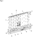
- Figure 3 shows a top view onto a rack of the instant disclosure showing the pullout leg supports 16 so that the rack can be safely placed onto a surface outside of the analyzer system without the danger of tipping over.
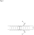
- Figure 4 shows in A on the left side an overview of the drive for agitating stationary bottles or container and in B on the right side a sectional view through the overview.
- Gear wheel 70 is mounted directly onto the motor shaft of motor 40 and engages into outer gear wheels 71.
- the outer gear wheels have on their upper side driver pins 72, which engage into the bottom side of stationary bottles or container 60 that are placed onto it and thus agitate the stationary bottles or container 60.
- an intelligent rack facilitates also the design of a loading bay and allows using racks of different width, wherein agitation of a rack is independent from the loading bay. Different sized containers or bottles can be supported within racks of a different width. The resulting high degree of flexibility for all kinds of substances is one advantage of the subject matter of the present invention.
- Racks according to the instant disclosure may be retrofitted even on already delivered instruments to allow for the use of cartridges according to the instant disclosure.
- a further advantage of a rack according to the instant disclosure is that the rack is able to recognize the content of a cartridge, which is placed onto the racks and can thus adapt for instance the agitation profile.
- cartridges which are inserted for the first time in a rack can be treated differently than during long term storage e.g. with more aggressive agitation for initial suspension of the content like settled particles or beads.
- a system using cartridges of the instant disclosure offers the possibility that agitation can be stopped rack wise rather than per loading bay, e.g. for pipettor access to a particular reagent.
- turning off agitation of individual racks may reduce noise generated from the agitation mechanism and reduces power consumption, in case that the particular rack is no longer needed for scheduled sample tests. Turning off agitation entirely due to the increased suspension capabilities of a rack of the instant disclosure can also reduce standby noise.
- LED indicators on the intelligent rack provide direct feed back to the user about the rack status e.g. in use, not in use - removable or not removable etc.
- a rack of the instant disclosure does not need a battery or electrical contacts due to the proposed use of induction coils. Thus, mechanical wear has no longer to be taken into account.
Abstract
Description
- The field of the invention relates to a rack for automated analyzer systems.
- Automatic analyzer systems in clinical diagnostics have to be supplied with different liquids to run biochemical processes and/ or have to be loaded with operating fluids for integrated technical devices.
- Currently analyzer systems use either individual bottles or cartridges. Individual bottles are inserted in racks, which are then placed into a reagent or sample-loading bay. Sample-loading bays are often cooled. Agitation for some contents to keep particles in suspension can be provided by some mechanical interface. On common instruments this mechanical interface is an oscillating gear rack or a gear wheel. This mechanical interface interacts with a gear on the rack, providing rotational movement to the reagent bottle or reagent container.
- Reagent cartridges combine several reagents into one container that has corresponding cavities. The cartridges are either placed directly into the reagent bay or via cartridge carriers. One or more inserted separate containers in the cartridge can be rotated for agitation. Cartridges offer a better reagent to space ratio than individual bottles.
- The existing reagent containers or cartridges cannot be agitated separately and are limited in respect to the width and the agitation interface.
- Agitation can only be used for all racks in a reagent bay simultaneously. If agitation needs to be stopped before pipetting, agitation is stopped for all racks during pipetting of one reagent. Thus, there is a need for cartridges, which can be agitated separately.
- Existing systems use bar code readers to identify rack and reagent type. Alternatively they use RFID antennas for reading out information. These antennas have to be placed very close to the respective tag, which causes additional efforts in protection against humidity. Optical systems like bar code readers or cameras are sensitive against condensation, e.g. in cooled systems or contamination with particles.
- The design of a loading bay is rather complex because of the need for agitation mechanism and agitation rack interface. Since a reagent bay is usually cooled, condensed water has to be taken into account.
- It is an object of the invention to provide a rack for automated analyser systems which provides more flexibility as regards agiation and identification of samples.
- The instant invention provides a rack for automated analyzer systems, the rack comprising at least one position for taking up at least one cartridge; at least one drive for agitating the content of the at least one cartridge; at least one RFID antenna for reading RFID tags of the at least one cartridge and at least one printed circuit board for operating the drive, e.g. a motor.
- The at least one cartridge may comprise at least one container or bottle.
- It is intended that at least one cartridge can comprise at least one stationary and/or movable container or bottle.
- The at least one drive and the at least one cartridge can be connected by means for agitating the at least one cartridge or the at least one container or bottle. A gear drive is one possible embodiment for such a connection.
- The at least one container or bottle of the at least one cartridge may be connected to at least one neighboring container to transfer its agitation. A row of gear drives may represent such a connection to transfer rotation from the drive.
- The rack may comprise induction coils to transfer power to the drive and to enable communication with the automated system for operation of the rack.
- The rack may further or alternatively comprise electrical contacts to transfer power and to enable communication with the automated system.
- The at least one cartridge may comprise 2D codes for identification.
- The rack may further comprise a LED to indicate the status of the rack to a user for instance.
- The rack may comprise a power source for powering the at least one drive.
- The at least one drive and the at least one cartridge or the at least one container or bottle may be connected by gear-wheels for agitation of the at least one cartridge.
- The rack may have pullout leg supports so that the rack is able to stand alone outside the automated analyzer system
- The invention will now be described on the basis of figures. It will be understood that the embodiments and aspects of the invention described in the figures are only examples and do not limit the protective scope of the claims in any way. The invention is defined by the claims and their equivalents. It will be understood that features of one aspect or embodiment of the invention can be combined with a feature of a different aspect or aspects of other embodiments of the invention. It shows:
-
Figure 1 Schematic overview of a rack with inserted cartridges -
Figure 2 Schematic overview of loading bays with inserted racks -
Figure 3 Top view onto a rack -
Figure 4 A: Schematic depiction of drive; B: Sectional view through A - The invention provides a new
intelligent rack 5 that acceptsdisposable cartridges 10 with any kind of content therein. Thecartridges 10 may only provide one volume or can be separated to provide separate volumes for different kinds of content.Figure 1 shows on the right part of the rack 5 acartridge 10 that is separated to have two parts for taking up content. - A rack within the meaning of the instant invention shall be understood as a framework into that cartridges or bottles may be placed. A rack can be put into an automated analyser system carrying cartridges or bottles with samples or buffer.
- The
intelligent rack 5 features a build in PCB 20, which carries RFID antennas for identification of inserted cartridges by reading outRFID tags 30, which are connected to the respective cartridge as well as a status LED. - The
rack 5 has a build inmotor 40, which provides agitation to at least onemovable cartridge 10 or container or bottle of acartridge 10. ThePCB 20 has an induction coil, which provides power to therack 5, when inserted into the reagent-loading bay. The reagent loading bay may feature corresponding induction coils to provide power to theracks 5. Information about the content of acartridge 10, container or bottle of acartridge 10 can be transmitted through the coils between therack 5 and the analyzer system. It is an advantage that arack 5 of the present disclosure enables individual agitation and further allows for different reagent specific agitation profiles without the need that the system provides a drive for agitation. The motor of a rack according to the instant invention is used for agitation of the content of a cartridge or bottle, but is not used for moving the rack or cartridges or bottles placed into the rack within the automated analyzer system. -
Figure 1 shows an embodiment of a newintelligent rack 5 with arack handle 15. One or more cartridges 10 (the figure shows a design for up to two cartridges10) can be inserted into therack 5. Eachcartridge 10 may have aRFID tag 30 containing information about the content of the respective cartridge. An antenna on therack PCB 20 can read out the RFID tag. Arecess 25 located at the bottom side can be used for locking the rack in the loading bay by a hook (not shown) engaging into the recess. - A processor on the
PCB 20 further controls theagitation motor 40, thestatus LED 50 and processes reagent data. ThePCB 20 communicates with the instrument electronics via an induction coil, which may also provide power to the rack. An identification of the content ofcartridge 10, comprised container or bottles can also be achieved by using barcodes on thecartridge 10. - The
cartridge 10 on the left side of the rack shown infigure 1 comprises 4 stationary container or bottles 60. The most right stationary container or bottle 60 is connected viagear wheel 70 with the motor or drive 40. - A
rack 5 may have aninterface 100 to communicate or exchange data with the automated analyzer system. The counterpart of the interface is located within the loading bay. -
Figure 2 shows lanes 80 of a loading bay comprising on the right side intelligent racks of the instant disclosure as well as an already known reagent racks. The lanes 80 do not need means for agitation, because they are integrated into the intelligent racks of the instant disclosure. - Fins 90 separate the loading bay into lanes and the fins 90 may provide cooling of the
cartridges 10 and their content. In casewider racks 5 are necessary, the fins 90 can be removed accordingly. This results in more flexibility for using a variety of racks and container with different sizes and shapes. -
Figure 3 shows a top view onto a rack of the instant disclosure showing the pullout leg supports 16 so that the rack can be safely placed onto a surface outside of the analyzer system without the danger of tipping over. -
Figure 4 shows in A on the left side an overview of the drive for agitating stationary bottles or container and in B on the right side a sectional view through the overview.Gear wheel 70 is mounted directly onto the motor shaft ofmotor 40 and engages intoouter gear wheels 71. The outer gear wheels have on their upper side driver pins 72, which engage into the bottom side of stationary bottles or container 60 that are placed onto it and thus agitate the stationary bottles or container 60. - The use of an intelligent rack according to the instant disclosure facilitates also the design of a loading bay and allows using racks of different width, wherein agitation of a rack is independent from the loading bay. Different sized containers or bottles can be supported within racks of a different width. The resulting high degree of flexibility for all kinds of substances is one advantage of the subject matter of the present invention.
- Racks according to the instant disclosure may be retrofitted even on already delivered instruments to allow for the use of cartridges according to the instant disclosure.
- The use of stationary coils and corresponding coils integrated into the rack allows for replacing moving parts for agitation in a loading bay. Thus, the reliability of a loading bay is improved. In case that a rack breaks, the user can replace such a rack without the help of field service engineering.
- A further advantage of a rack according to the instant disclosure is that the rack is able to recognize the content of a cartridge, which is placed onto the racks and can thus adapt for instance the agitation profile.
- It is further possible that cartridges which are inserted for the first time in a rack can be treated differently than during long term storage e.g. with more aggressive agitation for initial suspension of the content like settled particles or beads.
- A system using cartridges of the instant disclosure offers the possibility that agitation can be stopped rack wise rather than per loading bay, e.g. for pipettor access to a particular reagent.
- In addition, turning off agitation of individual racks may reduce noise generated from the agitation mechanism and reduces power consumption, in case that the particular rack is no longer needed for scheduled sample tests. Turning off agitation entirely due to the increased suspension capabilities of a rack of the instant disclosure can also reduce standby noise.
- LED indicators on the intelligent rack provide direct feed back to the user about the rack status e.g. in use, not in use - removable or not removable etc.
- A rack of the instant disclosure does not need a battery or electrical contacts due to the proposed use of induction coils. Thus, mechanical wear has no longer to be taken into account.
-
- 5
- rack
- 10
- cartridge
- 15
- rack handle
- 16
- leg support
- 20
- PCB
- 25
- recess
- 30
- RFID tag
- 40
- motor
- 50
- status LED
- 60
- stationary container or bottles
- 70
- gear wheel
- 71
- outer gear wheel
- 72
- driver pin
- 80
- lanes
- 90
- fin
- 100
- interface
Claims (12)
- A rack for automated analyzer systems, the rack comprising:- at least one position for taking up at least one cartridge;- at least one drive for agitating the content of the at least one cartridge;- at least one RFID antenna for reading RFID tags of the at least one cartridge and- at least one printed circuit board for operating the drive.
- The rack of claim 1, wherein the at least one cartridge comprises at least one container or bottle.
- The rack of claim 1 or 2, wherein the at least one cartridge comprises stationary and/or movable container.
- The rack of one of claims 1 to 3, wherein the at least one drive and the at least one cartridge are connected by means for agitating the at least one cartridge or the at least one container.
- The rack of claim 4, wherein the at least one container of the at least one cartridge is connected to at least one neighboring container to transfer its agitation.
- The rack of any one of claims 1 to 5, wherein the rack comprises induction coils to transfer power and communicate with the automated system.
- The rack of any one of claims 1 to 6, wherein the rack comprises electrical contacts to transfer power and communicate with the automated system
- The rack of any one of claims 1 to 7, wherein the at least one cartridge comprises barcodes or 2D-codes for identification.
- The rack of any one of claims 1 to 8, wherein the rack comprises a LED indicating the status of the rack to a user.
- The rack of one of claims 1 to 9, comprising a power source for powering the at least one drive.
- The rack of one of claims 1 to 8, wherein the at least one drive and the at least one cartridge or the at least one container are connected by gear-wheels for agitation of the at least one cartridge.
- The rack of one of claims 1 to 11, wherein the rack has pullout leg supports so that the rack is able to stand alone outside the automated analyzer system.
Applications Claiming Priority (1)
| Application Number | Priority Date | Filing Date | Title |
|---|---|---|---|
| LU92703A LU92703B1 (en) | 2015-04-29 | 2015-04-29 | Intelligent rack |
Publications (1)
| Publication Number | Publication Date |
|---|---|
| EP3088903A1 true EP3088903A1 (en) | 2016-11-02 |
Family
ID=53189113
Family Applications (1)
| Application Number | Title | Priority Date | Filing Date |
|---|---|---|---|
| EP16167708.3A Withdrawn EP3088903A1 (en) | 2015-04-29 | 2016-04-29 | Intelligent rack |
Country Status (3)
| Country | Link |
|---|---|
| US (1) | US20160320421A1 (en) |
| EP (1) | EP3088903A1 (en) |
| LU (1) | LU92703B1 (en) |
Cited By (1)
| Publication number | Priority date | Publication date | Assignee | Title |
|---|---|---|---|---|
| EP3544736B1 (en) * | 2018-02-19 | 2023-06-14 | Tecan Trading Ag | Sample rack and sample carrier system |
Families Citing this family (10)
| Publication number | Priority date | Publication date | Assignee | Title |
|---|---|---|---|---|
| US10058866B2 (en) | 2013-03-13 | 2018-08-28 | Abbott Laboratories | Methods and apparatus to mitigate bubble formation in a liquid |
| USD978375S1 (en) | 2013-03-13 | 2023-02-14 | Abbott Laboratories | Reagent container |
| USD962471S1 (en) * | 2013-03-13 | 2022-08-30 | Abbott Laboratories | Reagent container |
| US9535082B2 (en) | 2013-03-13 | 2017-01-03 | Abbott Laboratories | Methods and apparatus to agitate a liquid |
| ES2920382T3 (en) | 2015-11-16 | 2022-08-03 | Beckman Coulter Inc | Sample tube rack and sample tube analysis system |
| USD812243S1 (en) | 2016-07-28 | 2018-03-06 | Beckman Coulter, Inc. | Sample tube rack |
| USD808540S1 (en) | 2016-07-28 | 2018-01-23 | Beckman Coulter, Inc. | Sample tube rack |
| CN106732071A (en) * | 2016-12-31 | 2017-05-31 | 烟台德迈生物科技有限公司 | A kind of reagent automatic mixing device |
| USD938612S1 (en) | 2017-06-16 | 2021-12-14 | Beckman Coulter, Inc. | Sample rack |
| EP3932532A1 (en) * | 2018-07-25 | 2022-01-05 | TECAN Trading AG | Mixing device, mixing system and method for mixing substances in closed containers |
Citations (4)
| Publication number | Priority date | Publication date | Assignee | Title |
|---|---|---|---|---|
| US20080042839A1 (en) * | 2004-04-07 | 2008-02-21 | Matthias Grater | Device and Method for Identifying, Locating and Tracking Objects on Laboratory Equipment |
| WO2013177163A1 (en) * | 2012-05-24 | 2013-11-28 | Siemens Healthcare Diagnostics Inc. | Non-contact optical encoding scheme for intelligent automation puck |
| US20140277699A1 (en) * | 2011-05-13 | 2014-09-18 | Beckman Coulter, Inc. | Laboratory product transport element and path arrangement |
| US20140373747A1 (en) * | 2012-02-03 | 2014-12-25 | Siemens Healthcare Diagnostics Inc. | Power source for an automation system mechanism |
Family Cites Families (5)
| Publication number | Priority date | Publication date | Assignee | Title |
|---|---|---|---|---|
| US3300055A (en) * | 1964-12-14 | 1967-01-24 | Joseph H Rohr | Rack |
| US6588625B2 (en) * | 2001-04-24 | 2003-07-08 | Abbott Laboratories | Sample handling system |
| US8035485B2 (en) * | 2008-11-20 | 2011-10-11 | Abbott Laboratories | System for tracking vessels in automated laboratory analyzers by radio frequency identification |
| FR3000803B1 (en) * | 2013-01-04 | 2018-05-25 | Immunodiagnostic Systems France | ANALYSIS ASSEMBLY FOR ANALYSIS APPARATUS |
| WO2014144825A2 (en) * | 2013-03-15 | 2014-09-18 | Abbott Laboratories | Automated reagent manager of a diagnostic analyzer system |
-
2015
- 2015-04-29 LU LU92703A patent/LU92703B1/en active
-
2016
- 2016-04-29 EP EP16167708.3A patent/EP3088903A1/en not_active Withdrawn
- 2016-04-29 US US15/142,226 patent/US20160320421A1/en not_active Abandoned
Patent Citations (4)
| Publication number | Priority date | Publication date | Assignee | Title |
|---|---|---|---|---|
| US20080042839A1 (en) * | 2004-04-07 | 2008-02-21 | Matthias Grater | Device and Method for Identifying, Locating and Tracking Objects on Laboratory Equipment |
| US20140277699A1 (en) * | 2011-05-13 | 2014-09-18 | Beckman Coulter, Inc. | Laboratory product transport element and path arrangement |
| US20140373747A1 (en) * | 2012-02-03 | 2014-12-25 | Siemens Healthcare Diagnostics Inc. | Power source for an automation system mechanism |
| WO2013177163A1 (en) * | 2012-05-24 | 2013-11-28 | Siemens Healthcare Diagnostics Inc. | Non-contact optical encoding scheme for intelligent automation puck |
Cited By (1)
| Publication number | Priority date | Publication date | Assignee | Title |
|---|---|---|---|---|
| EP3544736B1 (en) * | 2018-02-19 | 2023-06-14 | Tecan Trading Ag | Sample rack and sample carrier system |
Also Published As
| Publication number | Publication date |
|---|---|
| LU92703B1 (en) | 2016-10-31 |
| US20160320421A1 (en) | 2016-11-03 |
Similar Documents
| Publication | Publication Date | Title |
|---|---|---|
| EP3088903A1 (en) | Intelligent rack | |
| US11226348B2 (en) | Storage module, method of operating a laboratory automation system and laboratory automation system | |
| JP7373635B2 (en) | System and method for reading machine-readable marks on racks and receptacles | |
| JP6148698B2 (en) | System for tracking liquid containers in laboratory automatic analyzers by wireless recognition | |
| US8715574B2 (en) | System for managing inventory of bulk liquids | |
| EP3218725B1 (en) | Double identification for sample tracking on a diagnostic device | |
| WO2010090138A1 (en) | Autoanalyzer and rack transfer method | |
| CN102224424B (en) | Automatic analysis device | |
| US9823261B2 (en) | Multi-well wedge-shaped reagent container with auto-open capability | |
| JP2018531391A6 (en) | System and method for reading machine readable marks on racks and receptacles | |
| JP2011027663A (en) | Automatic analyzing device | |
| JP2007309743A (en) | Multi-unit analyzer and its rack conveyance control method | |
| EP3203242B1 (en) | Automatic analysis device | |
| JP2006337386A (en) | Automatic analyzer | |
| US20200096526A1 (en) | Consumable management system for laboratories | |
| JP2010256051A (en) | Autoanalyzer | |
| CN113490853B (en) | automatic analysis device | |
| GB2534844A (en) | Reagent manager | |
| EP3825006A1 (en) | Rack for automated analyzer | |
| JP2009244238A (en) | Automatic analyzer | |
| CN114521236A (en) | Automatic analyzer | |
| JP7449924B2 (en) | Transport mechanism and analysis device | |
| GB2532780A (en) | Reagent cartridge | |
| WO2023073667A1 (en) | Consumables container loading/unloading system and method of loading/unloading consumables containers for automated analyzer |
Legal Events
| Date | Code | Title | Description |
|---|---|---|---|
| PUAI | Public reference made under article 153(3) epc to a published international application that has entered the european phase |
Free format text: ORIGINAL CODE: 0009012 |
|
| AK | Designated contracting states |
Kind code of ref document: A1 Designated state(s): AL AT BE BG CH CY CZ DE DK EE ES FI FR GB GR HR HU IE IS IT LI LT LU LV MC MK MT NL NO PL PT RO RS SE SI SK SM TR |
|
| AX | Request for extension of the european patent |
Extension state: BA ME |
|
| 17P | Request for examination filed |
Effective date: 20170502 |
|
| RBV | Designated contracting states (corrected) |
Designated state(s): AL AT BE BG CH CY CZ DE DK EE ES FI FR GB GR HR HU IE IS IT LI LT LU LV MC MK MT NL NO PL PT RO RS SE SI SK SM TR |
|
| RAP1 | Party data changed (applicant data changed or rights of an application transferred) |
Owner name: STRATEC SE |
|
| 17Q | First examination report despatched |
Effective date: 20191001 |
|
| STAA | Information on the status of an ep patent application or granted ep patent |
Free format text: STATUS: THE APPLICATION IS DEEMED TO BE WITHDRAWN |
|
| 18D | Application deemed to be withdrawn |
Effective date: 20200212 |