EP3088760A1 - Electromagnetic clutch having improved clutch pull force - Google Patents
Electromagnetic clutch having improved clutch pull force Download PDFInfo
- Publication number
- EP3088760A1 EP3088760A1 EP16166308.3A EP16166308A EP3088760A1 EP 3088760 A1 EP3088760 A1 EP 3088760A1 EP 16166308 A EP16166308 A EP 16166308A EP 3088760 A1 EP3088760 A1 EP 3088760A1
- Authority
- EP
- European Patent Office
- Prior art keywords
- annular wall
- coil housing
- thickness
- electromagnetic clutch
- clutch device
- Prior art date
- Legal status (The legal status is an assumption and is not a legal conclusion. Google has not performed a legal analysis and makes no representation as to the accuracy of the status listed.)
- Granted
Links
Images


Classifications
-
- B—PERFORMING OPERATIONS; TRANSPORTING
- B60—VEHICLES IN GENERAL
- B60H—ARRANGEMENTS OF HEATING, COOLING, VENTILATING OR OTHER AIR-TREATING DEVICES SPECIALLY ADAPTED FOR PASSENGER OR GOODS SPACES OF VEHICLES
- B60H1/00—Heating, cooling or ventilating [HVAC] devices
- B60H1/00421—Driving arrangements for parts of a vehicle air-conditioning
-
- F—MECHANICAL ENGINEERING; LIGHTING; HEATING; WEAPONS; BLASTING
- F16—ENGINEERING ELEMENTS AND UNITS; GENERAL MEASURES FOR PRODUCING AND MAINTAINING EFFECTIVE FUNCTIONING OF MACHINES OR INSTALLATIONS; THERMAL INSULATION IN GENERAL
- F16D—COUPLINGS FOR TRANSMITTING ROTATION; CLUTCHES; BRAKES
- F16D27/00—Magnetically- or electrically- actuated clutches; Control or electric circuits therefor
- F16D27/02—Magnetically- or electrically- actuated clutches; Control or electric circuits therefor with electromagnets incorporated in the clutch, i.e. with collecting rings
-
- F—MECHANICAL ENGINEERING; LIGHTING; HEATING; WEAPONS; BLASTING
- F16—ENGINEERING ELEMENTS AND UNITS; GENERAL MEASURES FOR PRODUCING AND MAINTAINING EFFECTIVE FUNCTIONING OF MACHINES OR INSTALLATIONS; THERMAL INSULATION IN GENERAL
- F16D—COUPLINGS FOR TRANSMITTING ROTATION; CLUTCHES; BRAKES
- F16D27/00—Magnetically- or electrically- actuated clutches; Control or electric circuits therefor
- F16D27/10—Magnetically- or electrically- actuated clutches; Control or electric circuits therefor with an electromagnet not rotating with a clutching member, i.e. without collecting rings
- F16D27/108—Magnetically- or electrically- actuated clutches; Control or electric circuits therefor with an electromagnet not rotating with a clutching member, i.e. without collecting rings with axially movable clutching members
- F16D27/112—Magnetically- or electrically- actuated clutches; Control or electric circuits therefor with an electromagnet not rotating with a clutching member, i.e. without collecting rings with axially movable clutching members with flat friction surfaces, e.g. discs
-
- F—MECHANICAL ENGINEERING; LIGHTING; HEATING; WEAPONS; BLASTING
- F16—ENGINEERING ELEMENTS AND UNITS; GENERAL MEASURES FOR PRODUCING AND MAINTAINING EFFECTIVE FUNCTIONING OF MACHINES OR INSTALLATIONS; THERMAL INSULATION IN GENERAL
- F16D—COUPLINGS FOR TRANSMITTING ROTATION; CLUTCHES; BRAKES
- F16D27/00—Magnetically- or electrically- actuated clutches; Control or electric circuits therefor
- F16D27/14—Details
-
- B—PERFORMING OPERATIONS; TRANSPORTING
- B60—VEHICLES IN GENERAL
- B60K—ARRANGEMENT OR MOUNTING OF PROPULSION UNITS OR OF TRANSMISSIONS IN VEHICLES; ARRANGEMENT OR MOUNTING OF PLURAL DIVERSE PRIME-MOVERS IN VEHICLES; AUXILIARY DRIVES FOR VEHICLES; INSTRUMENTATION OR DASHBOARDS FOR VEHICLES; ARRANGEMENTS IN CONNECTION WITH COOLING, AIR INTAKE, GAS EXHAUST OR FUEL SUPPLY OF PROPULSION UNITS IN VEHICLES
- B60K25/00—Auxiliary drives
- B60K25/02—Auxiliary drives directly from an engine shaft
- B60K2025/022—Auxiliary drives directly from an engine shaft by a mechanical transmission
-
- B—PERFORMING OPERATIONS; TRANSPORTING
- B60—VEHICLES IN GENERAL
- B60K—ARRANGEMENT OR MOUNTING OF PROPULSION UNITS OR OF TRANSMISSIONS IN VEHICLES; ARRANGEMENT OR MOUNTING OF PLURAL DIVERSE PRIME-MOVERS IN VEHICLES; AUXILIARY DRIVES FOR VEHICLES; INSTRUMENTATION OR DASHBOARDS FOR VEHICLES; ARRANGEMENTS IN CONNECTION WITH COOLING, AIR INTAKE, GAS EXHAUST OR FUEL SUPPLY OF PROPULSION UNITS IN VEHICLES
- B60K25/00—Auxiliary drives
- B60K25/02—Auxiliary drives directly from an engine shaft
-
- F—MECHANICAL ENGINEERING; LIGHTING; HEATING; WEAPONS; BLASTING
- F16—ENGINEERING ELEMENTS AND UNITS; GENERAL MEASURES FOR PRODUCING AND MAINTAINING EFFECTIVE FUNCTIONING OF MACHINES OR INSTALLATIONS; THERMAL INSULATION IN GENERAL
- F16D—COUPLINGS FOR TRANSMITTING ROTATION; CLUTCHES; BRAKES
- F16D27/00—Magnetically- or electrically- actuated clutches; Control or electric circuits therefor
- F16D2027/008—Details relating to the magnetic circuit, or to the shape of the clutch parts to achieve a certain magnetic path
Definitions
- the invention relates to a compressor used in an air conditioning system, more specifically to an electromagnetic clutch device for the compressor.
- the compressor In vehicle air conditioning systems, compressors are only operated when needed.
- the compressor typically includes a rotatable crank shaft, a rotatable pulley assembly to be driven via a belt or a chain, and a clutch coupling and decoupling the crank shaft and the pulley assembly.
- electromagnetic clutches are used that include a coil that, when energized bring an armature plate in contact with the rotor body.
- the armature plate which is mounted on the crank shaft in a rotationally fixed and axially displaceable manner, is thus frictionally coupled to the pulley assembly and rotates therewith.
- a rotation of the pulley assembly results in a rotation of the crank shaft.
- an electromagnetic clutch device for a compressor comprises a crank shaft with an inner shaft end accommodated in a compressor housing and with an outer shaft end projecting axially out of the compressor housing.
- a pulley assembly with a rotor body and a pulley fixedly attached thereto, has a toroidal cavity accommodating a coil housing and is rotatably supported on the compressor housing by a pulley bearing.
- the coil housing includes a radially inner annular wall, a radially outer annular wall, an axially open end facing the outer shaft end, and a bottom extending radially from the radially inner annular wall to the radially outer annular wall at an axial end of the coil housing proximate the inner shaft end.
- An armature plate adjacent the rotor body is connected to the outer shaft end in an axially displaceable manner so as to rotate with the crank shaft.
- the inner annular wall and the outer annular wall of the coil housing each have an outer surface, the outer surfaces having a greater distance from one another near the bottom of the coil housing than proximate the axially open end. This allows for a greater magnetic flux through the coil housing than previously possible without affecting the space available for the coil within the coil housing.
- Additional material is preferably provided in such a manner that the inner annular wall of the coil has a first thickness near the bottom of the coil housing and a second thickness at the axially open end, that the outer annular wall has a third thickness near the bottom of the coil housing and a fourth thickness at the axially open end, so that the difference between the first thickness and the second thickness is greater than the difference between the third thickness and the fourth thickness.
- the first thickness is greater than the second thickness by 40% to 100%, in particular by 50% to 80%.
- the third thickness is greater than the fourth thickness by at most 50%, in particular by 15% through 30%.
- the material added to the coil housing is distributed in such a manner that the inner annular wall of the coil housing has a top distance from the crank shaft at the top end and a bottom distance from the crank shaft at the bottom end, and that a sloped portion disposed between the top end and the bottom end forms a taper connecting the different distances from the crank shaft.
- the top portion and the bottom portion of the inner annular wall may be cylindrical. This geometry allows for easy modeling by simulations moving the taper closer to the bottom or to the open end of the coil housing.
- the material added to the coil housing is distributed in such a manner that the outer annular wall of the coil housing has a top distance from the crank shaft at the top end and a bottom distance from the crank shaft at the bottom end, and that a sloped portion disposed between the top end and the bottom end forms a taper connecting the different distances from the crank shaft.
- the top portion and the bottom portion of the outer annular wall may be cylindrical. This geometry allows for easy modeling by simulations moving the taper closer to the bottom or to the open end of the coil housing.
- the inner annular wall may have a greater axial length than the outer annular wall for a more even distribution of the magnetic flux density over the cross-section of the coil housing.
- the pulley and the rotor body may be formed as one monolithic part.
- a compressor 10 for an automobile includes a compressor housing 12 and a pulley assembly 14.
- the pulley assembly 14 includes a rotor body 16 and a pulley 18 with sheaves 20.
- the pulley assembly 14 is rotatably mounted onto the compressor housing 12 and is adapted to engage a belt or chain (not shown) that transfers rotational movement to the pulley assembly 14 from the engine of the automobile or alternatively from an electric motor.
- the rotor body 16 and the pulley 18 are shown as one monolithic part.
- the pulley assembly 14 may, however also be formed from a rotor body 16 and a pulley 18 that are fixedly secured to each other in a suitable manner.
- the compressor 10 includes a crank shaft 22 that is rotatably mounted within the compressor housing 12.
- the crank shaft has an inner end 24 inside the compressor housing and an outer end 26 projecting out of the compressor housing.
- the crank shaft 22 drives the inner components of the compressor 10 that are not shown in greater detail.
- the crank shaft 22 is supported within the compressor 10 by a shaft bearing 28. This shaft bearing 28 allows the crank shaft 22 to rotate relative to the compressor housing 12.
- the pulley assembly 14 is supported on the compressor housing 12 by a pulley bearing 30.
- the pulley bearing 30 allows the pulley assembly 14 to rotate relative to the compressor housing 12.
- the compressor 10 includes an electromagnetic clutch 32 to selectively connect the pulley assembly 14 to the crank shaft 22 such that rotation of the pulley assembly 14 is transferred to the crank shaft 22 to drive the compressor 10.
- the electromagnetic clutch 32 includes an armature plate 34 that is mounted onto the outer end 26 of the crank shaft 22 via a clutch hub 36.
- the armature plate 34 is mounted in such a way that the armature plate 34 rotates with the crank shaft 22, but is allowed to move axially with respect to the crank shaft 22 and the compressor housing 12.
- the armature plate 34 has a disengaged position, in which an axial gap exists between the armature plate 34 and the pulley assembly 14. In this position, the pulley assembly 14 is free to rotate relative to the crank shaft 22, and no rotational motion is transferred to the armature plate 34.
- the armature plate 34 can move to an engaged position where the armature plate 34 contacts the rotor body 16.
- friction between the rotor body 16 and the armature plate 34 will cause the rotational movement of the pulley assembly 14 to be transferred from the rotor body 16 to the armature plate 34 and thus to the crank shaft 22.
- an electromagnetic coil assembly 38 is disposed in a toroidal cavity 40.
- the coil assembly 38 includes at least one coil in a coil housing 42 extending around the crank shaft 22 and placed in the toroidal cavity 40.
- the coil housing 42 has an axial inner annular wall 44, an axial outer annular wall 46, and a radially extending annular bottom 48 radially extending from the outer annular wall 46 to the inner annular wall 44.
- the bottom 48 of the coil housing 42 closes the open side of the toroidal cavity 40 of the rotor body 16 that faces the inner end 24 of the crank shaft 22.
- a ring disc radially 50 extending between the compressor housing 12 and the coil housing 42 protects the pulley bearing 30 from contamination.
- a magnetic field is generated.
- the coil housing 42 directs the electromagnetic field axially outward through the bottom of the rotor body 16 and across the gap, such that the magnetic field draws the armature plate 34 axially toward the rotor body 16. Once the armature plate 34 contacts the rotor body 16, the magnetic field will keep the armature plate 34 in contact with the rotor body 16 so that a rotational movement from the pulley assembly 14 will be frictionally transferred to the armature plate 34.
- An objective of a typical clutch design is to maximize magnetic strength to engage the armature plate 34 and minimize the power consumption.
- a common arrangement of current clutch technology provides that the rotor body 16 and the coil assembly 38 are nested with one another. This typical arrangement may be less than ideal because it may result in a localized magnetic flux saturation of the surrounding steel. This localized magnetic flux saturation of the steel puts a limit on the entire magnetic flux circuit in the clutch 32. The magnetic flux saturation thus limits the magnetic attraction of the armature plate 34 and thereby the clutch strength by reducing the magnetomotive force exerted by the coil assembly 38.
- the magnetomotive force is the product of current flow multiplied by the number of windings ("turns") in a given coil design and is represented in units of Ampere-turns, where 1 Ampere-turn is the magnetomotive force generated by a direct current of 1 Ampere flowing in a coil of 1 winding.
- This magnetomotive force is used to simulate the magnetic pull force for a given clutch design. This restriction of the magnetomotive force due to magnetic flux saturation can be seen in Figure 3 , near the bottom 48 of the coil housing 42.
- the magnetic flux In a transitional area, in which the bottom 48 of the coil housing 42 meets the inner annular wall 44 and the outer annular wall 46 of the coil housing 42, the magnetic flux has a very high density and is saturated due to the lack of steel material to transmit the magnetic flux. This lack of material causes a bottleneck effect on the magnetic flux.
- the shape of the pulley 18 and the pulley size place limits on how much additional material can be added to the coil housing 42 in the transitional area.
- the pulley 18, however, is undersaturated with magnetic flux near the transitional area of the coil housing 42. For generating a sufficient magnetic flux, less material is required in this portion of the pulley 18 because the magnetic flux density in the remaining material can be increased without excessive saturation.
- This realization helps in constructing a paired assembly of a rotor body 16 and a coil housing 42 that mitigates the saturation in the transitional area of the coil housing 42.
- the annular walls 44 and 46 of the coil housing 42 are thicker in a bottom portion 52 of the coil housing 42 than remote from the bottom 48 of the coil housing 42. This is accomplished by placing the outer surfaces 56 and 58 of the inner annular wall 44 and of the outer annular wall 46 farther apart from each other near the bottom 48 of the coil housing 42 than near the open axial end of the coil housing 42. The material added to the coil housing 42 thus does not affect the interior space of the coil housing 42 that accommodates the coil assembly 38.
- the cross-section of the interior space of the coil housing 42 remains generally cylindrical or slightly trapezoidal as generally known from the prior art.
- the interior space may widen slightly between the inner and outer annular walls 44 and 46 in the axial direction from the bottom 48 of the coil housing 42 to the open end of the coil housing 42, the distance of the inner walls increases by a lesser amount than the amount by which the distance of the outer surfaces 56 and 58 is reduced in the axial direction from the bottom 48 of the coil housing 42 to the open end.
- the added material near the bottom 48 of the coil housing 42 increases the thickness of the inner annular wall 44 by 40% to 100% of the wall thickness near the axially open end, preferably by 50% to 80%.
- the thickness of the outer annular wall 46 is increased by up to 50%, preferably by 15% through 30%.
- the expanded design of the bottom portion 52 of the coil housing 42 allows more material to be in the bottom portion 52 of the coil housing 42 to lessen the restriction of the magnetic flux.
- the area in the vicinity of the bottom portion 52 which is under-saturated with magnetic flux density in conventional designs, contains less material where it can still achieve the same overall magnetic flux necessary for this area via an increased magnetic flux density.
- Figures 4 and 5 show a first embodiment of the invention with a widened bottom portion 52 of the coil housing 42.
- the inner and outer annular walls 44 and 46 lessen the magnetic flux density in the bottom portion 52 of the coil housing 42, while the conventionally undersaturated areas of the rotor body 16 reach a higher magnetic flux density than in conventional designs, which is an indication that saturation has just started.
- the annular walls 44 and 46 of the coil housing 42 are composed of three portions.
- the inner and outer annular walls 44 and 46 have outer surfaces 56 and 58 that extend generally parallel to each other.
- the outer surfaces 56 and 58 of the inner and outer annular walls 44 and 46 also extend parallel to each other, however at a smaller distance from each other than in the bottom portion 52.
- a sloped portion 60 connecting the top portion 54 and the bottom portion 52 includes a taper that creates a transition between the greater distance of the outer surfaces 56 and 58 of the bottom portion 52 and the smaller distance of the outer surfaces 56 and 58 of the top portion 54.
- the radially inward taper of the inner annular wall 44 of the coil housing 42 toward the coil housing bottom 48 may bridge a greater radial step with respect to the distance from the crank shaft 22 than the radially outward taper on the outer annular wall 46 of the coil housing 42.
- more material is added to the outer surface 56 of the inner annular wall 44 of the coil housing 42 than to the outer surface 58 of the outer annular wall 46.
- the inner annular wall 44 of the coil housing 42 exhibits a greater difference in thickness between the thickness D1 of the bottom portion 52 and the thickness D2 at the open end in the top portion 54 of the coil housing 42 than the difference between the thickness D3 of the outer annular wall 46 in the bottom portion 52 and the thickness D4 in the top portion 54.
- the geometry of the coil housing 42 and the pulley 18 can be manipulated in a virtual model until the magnetic flux density is most evenly distributed over the cross-section of the coil housing 42 and potentially even over the cross-section of the rotor body 16. A uniform distribution is likely not attainable due to the geometrical limitations. But a significant improvement over conventional arrangements can be achieved to maximize the magnetic pull force.
- the maximized pull force allows a design to reduce the amount of magnet wire used in the coil assembly 38, resulting in lower mass and cost. Possibly, a smaller coil assembly 38 can be used, which also reduces the packaging size and reduces the overall length of the pulley 18, thereby further reducing the amount of steel required for the pulley assembly 14.
- Figures 6 and 7 show variations of the embodiment of Figs. 4 and 5 .
- the sloped portion 60 is moved closer to the bottom 48 of the coil housing 42 so that the top portion 54 occupies most of the inner and outer annular walls 44 and 46.
- the top portion 54 is shortened by moving the sloped portion 60 upward relative to the embodiment of Figs. 4 and 5.
- Figs. 6 and 7 illustrate the effects of varying the location of the sloped portion 60 of the coil housing 42 that extends between the widened bottom portion 52 and the top portion 54 that has not been widened.
- Figs. 6 and 7 also illustrate how the shape of the toroidal cavity 40 within the rotor body 16 is adapted to the shape of the coil housing 42 with corresponding tapers in the wall of the toroidal cavity 40.
- the taper could be added on the inside surfaces of the annular walls 44 and 46 of the coil housing 42 to widen the bottom portion 52 but the addition of material in this area is limited due to the size of the coil assembly 38, which is made of copper or aluminum wire.
- an alternative manner of adding material to the bottom portion 52 of the coil housing 42 involves adding a cross sectional taper 62 to the outside surfaces of the annular walls 44 and 46 of the coil housing 42 along the entire axial length of the inner and outer annular walls 44 and 46 of the coil housing 42.
- This taper 62 extends the sloped portion 60 of the embodiments of Figs. 4 through 7 over the entire axial length of the coil housing 42.
- adding the taper cross section inside the coil housing 42 has a negative side effect of restricting the coil size and thereby the magnetomotive force achievable with a standard coil in the remaining space.
- the toroidal cavity 40 of the pulley 18 is correspondingly tapered and widens toward the bottom 48 of the coil housing 42.
- the greatest distance between the outer surfaces 56 and 58 of the inner and outer walls of the coil housing 42 exists in the bottom portion 52 of the coil housing 42, which is the portion axially closest to the bottom 48 of the coil housing 42.
- the smallest distance between these two outer surfaces 56 and 58 is found near the open end of the coil housing 42, axially opposite the bottom 48 of the coil housing 42.
- the radially inward taper 62 of the inner annular wall 44 of the coil housing 42 toward the coil housing bottom 48 may form a greater angle with respect to the axis of rotation than the radially outward taper 62 on the outer annular wall 46 of the coil housing 42.
- the inner annular wall 44 of the coil housing 42 exhibits a greater different in thickness between the bottom portion 52 and the open end of the coil housing 42 than the outer annular wall 46. As shown in Fig.
- the entire volume of added material may even be incorporated on the inner annular wall 44, while the outer annular wall 46 has a nearly cylindrical shape.
- the toroidal cavity 40 of the pulley 18 again has a complementary shape reflecting the inward and outward tapers 62 of the coil housing 42.
- the improved shapes of the coil housing 42 and the pulley 18 equalize the magnetic saturation of the arrangement while maintaining the space for the coil assembly 38.
- the pulley 18 of Figs. 4 and 6-8 shows the pulley sheaves 20 formed on a ring-shaped disc extending radially from the rotor body 16 to the pulley sheaves 20.
- Figs. 1 , 2 , and 5 show the sheaves 20 formed directly on the rotor body 16. While the radial separation of the sheaves 20 from the rotor body 16 as shown in figs. 4 and 6-8 may affect the magnetic flux density within the rotor body 16, the rationales provided are applicable to both designs and any other designs that provide a toroidal cavity 40 accommodating the coil assembly 38.
- the sheaves 20 can be dimensioned to have any desired diameter, while the coil housing 42 and the toroidal cavity 40 can be improved by applying the designs of any one of Figs. 4-8 or a combination of various designs.
- the top and bottom portions 54 and 52 of figs. 4-7 could be tapered as well as shown in Fig. 8 , and the sloped portion 60 may merely have a steeper slope than the top portion 54 and the bottom portion 52. Any other contours are feasible that add more material to the bottom portion 52 compared to the top portion 54.
- the inner annular wall 44 has a greater axial length than the outer annular wall 46.
- the inner annular wall 44 extends closer toward the armature plate 34 than the outer annular wall 46.
- this geometry results in a more even distribution of the magnetic flux density.
- the axial length of the inner and outer annular walls 44 and 46 of the coil housing 42 may be varied, for example in further simulations, to optimize the magnetic flux.
Abstract
Description
- The invention relates to a compressor used in an air conditioning system, more specifically to an electromagnetic clutch device for the compressor.
- In vehicle air conditioning systems, compressors are only operated when needed. Thus, in order to couple the compressor to a drive mechanism, the compressor typically includes a rotatable crank shaft, a rotatable pulley assembly to be driven via a belt or a chain, and a clutch coupling and decoupling the crank shaft and the pulley assembly.
- Customarily, electromagnetic clutches are used that include a coil that, when energized bring an armature plate in contact with the rotor body. The armature plate, which is mounted on the crank shaft in a rotationally fixed and axially displaceable manner, is thus frictionally coupled to the pulley assembly and rotates therewith. Thus, a rotation of the pulley assembly results in a rotation of the crank shaft.
- While this type of arrangement is generally known and reliable, it is an objective of the present invention to optimize the function of the clutch.
- According to one aspect of the present invention, an electromagnetic clutch device for a compressor comprises a crank shaft with an inner shaft end accommodated in a compressor housing and with an outer shaft end projecting axially out of the compressor housing. Further, a pulley assembly, with a rotor body and a pulley fixedly attached thereto, has a toroidal cavity accommodating a coil housing and is rotatably supported on the compressor housing by a pulley bearing. The coil housing includes a radially inner annular wall, a radially outer annular wall, an axially open end facing the outer shaft end, and a bottom extending radially from the radially inner annular wall to the radially outer annular wall at an axial end of the coil housing proximate the inner shaft end. An armature plate adjacent the rotor body is connected to the outer shaft end in an axially displaceable manner so as to rotate with the crank shaft. The inner annular wall and the outer annular wall of the coil housing each have an outer surface, the outer surfaces having a greater distance from one another near the bottom of the coil housing than proximate the axially open end. This allows for a greater magnetic flux through the coil housing than previously possible without affecting the space available for the coil within the coil housing.
- Additional material is preferably provided in such a manner that the inner annular wall of the coil has a first thickness near the bottom of the coil housing and a second thickness at the axially open end, that the outer annular wall has a third thickness near the bottom of the coil housing and a fourth thickness at the axially open end, so that the difference between the first thickness and the second thickness is greater than the difference between the third thickness and the fourth thickness.
- Preferably, the first thickness is greater than the second thickness by 40% to 100%, in particular by 50% to 80%.
- Further, preferably, the third thickness is greater than the fourth thickness by at most 50%, in particular by 15% through 30%.
- According to one aspect of the invention, the material added to the coil housing is distributed in such a manner that the inner annular wall of the coil housing has a top distance from the crank shaft at the top end and a bottom distance from the crank shaft at the bottom end, and that a sloped portion disposed between the top end and the bottom end forms a taper connecting the different distances from the crank shaft.
- For example, the top portion and the bottom portion of the inner annular wall may be cylindrical. This geometry allows for easy modeling by simulations moving the taper closer to the bottom or to the open end of the coil housing.
- According to another aspect of the invention, the material added to the coil housing is distributed in such a manner that the outer annular wall of the coil housing has a top distance from the crank shaft at the top end and a bottom distance from the crank shaft at the bottom end, and that a sloped portion disposed between the top end and the bottom end forms a taper connecting the different distances from the crank shaft.
- For example, the top portion and the bottom portion of the outer annular wall may be cylindrical. This geometry allows for easy modeling by simulations moving the taper closer to the bottom or to the open end of the coil housing.
- The inner annular wall may have a greater axial length than the outer annular wall for a more even distribution of the magnetic flux density over the cross-section of the coil housing.
- For simplifying the manufacturing process, the pulley and the rotor body may be formed as one monolithic part.
- Further details and benefits will become apparent from the following description of the accompanying drawings. The drawings are provided purely for illustrative purposes and are not intended to limit the scope of the present invention.
- In the drawings,
-
Fig. 1 shows a side view of a compressor with a pulley assembly; -
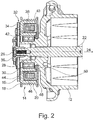
Fig. 2 shows a cross-section through a pulley assembly, a customary clutch, and a crank shaft of a compressor of the type shown inFig. 1 ; -
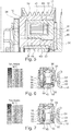
Fig. 3A shows a simulation of the magnetic flux density in a pulley assembly as shown inFig. 2 ; -
Fig. 3B shows magnetic flux lines through a pulley assembly as shown inFig. 2 ; -
Fig. 4 shows a simulation of the magnetic flux density in a pulley assembly according to a first embodiment of the present invention; -
Fig. 5 shows a cross-section through a pulley assembly and a clutch similar to the embodiment ofFig. 4 , but with a different pulley assembly; -
Fig. 6 shows a simulation of the magnetic flux density in a pulley assembly according to a third embodiment of the present invention; -
Fig. 7 shows a simulation of the magnetic flux density in a pulley assembly according to a fourth embodiment of the present invention; and -
Fig. 8 shows a simulation of the magnetic flux density in a pulley assembly according to a fifth embodiment of the present invention. - As shown in
Fig. 1 , acompressor 10 for an automobile includes acompressor housing 12 and apulley assembly 14. Thepulley assembly 14 includes arotor body 16 and apulley 18 withsheaves 20. Thepulley assembly 14 is rotatably mounted onto thecompressor housing 12 and is adapted to engage a belt or chain (not shown) that transfers rotational movement to thepulley assembly 14 from the engine of the automobile or alternatively from an electric motor. In the shown embodiments, therotor body 16 and thepulley 18 are shown as one monolithic part. Thepulley assembly 14 may, however also be formed from arotor body 16 and apulley 18 that are fixedly secured to each other in a suitable manner. - As shown in
Fig. 2 , thecompressor 10 includes acrank shaft 22 that is rotatably mounted within thecompressor housing 12. The crank shaft has aninner end 24 inside the compressor housing and anouter end 26 projecting out of the compressor housing. Thecrank shaft 22 drives the inner components of thecompressor 10 that are not shown in greater detail. Thecrank shaft 22 is supported within thecompressor 10 by a shaft bearing 28. This shaft bearing 28 allows thecrank shaft 22 to rotate relative to thecompressor housing 12. Thepulley assembly 14 is supported on thecompressor housing 12 by a pulley bearing 30. The pulley bearing 30 allows thepulley assembly 14 to rotate relative to thecompressor housing 12. - The
compressor 10 includes anelectromagnetic clutch 32 to selectively connect thepulley assembly 14 to thecrank shaft 22 such that rotation of thepulley assembly 14 is transferred to thecrank shaft 22 to drive thecompressor 10. Theelectromagnetic clutch 32 includes anarmature plate 34 that is mounted onto theouter end 26 of thecrank shaft 22 via aclutch hub 36. Thearmature plate 34 is mounted in such a way that thearmature plate 34 rotates with thecrank shaft 22, but is allowed to move axially with respect to thecrank shaft 22 and thecompressor housing 12. - The
armature plate 34 has a disengaged position, in which an axial gap exists between thearmature plate 34 and thepulley assembly 14. In this position, thepulley assembly 14 is free to rotate relative to thecrank shaft 22, and no rotational motion is transferred to thearmature plate 34. - However, the
armature plate 34 can move to an engaged position where thearmature plate 34 contacts therotor body 16. When thearmature plate 34 is in contact with therotor body 16, friction between therotor body 16 and thearmature plate 34 will cause the rotational movement of thepulley assembly 14 to be transferred from therotor body 16 to thearmature plate 34 and thus to thecrank shaft 22. - Within the
rotor body 16, anelectromagnetic coil assembly 38 is disposed in atoroidal cavity 40. Thecoil assembly 38 includes at least one coil in acoil housing 42 extending around thecrank shaft 22 and placed in thetoroidal cavity 40. Thecoil housing 42 has an axial innerannular wall 44, an axial outerannular wall 46, and a radially extendingannular bottom 48 radially extending from the outerannular wall 46 to the innerannular wall 44. The bottom 48 of thecoil housing 42 closes the open side of thetoroidal cavity 40 of therotor body 16 that faces theinner end 24 of thecrank shaft 22. A ring disc radially 50 extending between thecompressor housing 12 and thecoil housing 42 protects the pulley bearing 30 from contamination. - When a current flows through the
coil assembly 38, a magnetic field is generated. Thecoil housing 42 directs the electromagnetic field axially outward through the bottom of therotor body 16 and across the gap, such that the magnetic field draws thearmature plate 34 axially toward therotor body 16. Once thearmature plate 34 contacts therotor body 16, the magnetic field will keep thearmature plate 34 in contact with therotor body 16 so that a rotational movement from thepulley assembly 14 will be frictionally transferred to thearmature plate 34. - An objective of a typical clutch design is to maximize magnetic strength to engage the
armature plate 34 and minimize the power consumption. - A common arrangement of current clutch technology provides that the
rotor body 16 and thecoil assembly 38 are nested with one another. This typical arrangement may be less than ideal because it may result in a localized magnetic flux saturation of the surrounding steel. This localized magnetic flux saturation of the steel puts a limit on the entire magnetic flux circuit in the clutch 32. The magnetic flux saturation thus limits the magnetic attraction of thearmature plate 34 and thereby the clutch strength by reducing the magnetomotive force exerted by thecoil assembly 38. The magnetomotive force is the product of current flow multiplied by the number of windings ("turns") in a given coil design and is represented in units of Ampere-turns, where 1 Ampere-turn is the magnetomotive force generated by a direct current of 1 Ampere flowing in a coil of 1 winding. This magnetomotive force is used to simulate the magnetic pull force for a given clutch design. This restriction of the magnetomotive force due to magnetic flux saturation can be seen inFigure 3 , near the bottom 48 of thecoil housing 42. - In a transitional area, in which the bottom 48 of the
coil housing 42 meets the innerannular wall 44 and the outerannular wall 46 of thecoil housing 42, the magnetic flux has a very high density and is saturated due to the lack of steel material to transmit the magnetic flux. This lack of material causes a bottleneck effect on the magnetic flux. - The shape of the
pulley 18 and the pulley size place limits on how much additional material can be added to thecoil housing 42 in the transitional area. Thepulley 18, however, is undersaturated with magnetic flux near the transitional area of thecoil housing 42. For generating a sufficient magnetic flux, less material is required in this portion of thepulley 18 because the magnetic flux density in the remaining material can be increased without excessive saturation. - This realization helps in constructing a paired assembly of a
rotor body 16 and acoil housing 42 that mitigates the saturation in the transitional area of thecoil housing 42. - According to a first aspect of the invention, the
annular walls coil housing 42 are thicker in abottom portion 52 of thecoil housing 42 than remote from the bottom 48 of thecoil housing 42. This is accomplished by placing the outer surfaces 56 and 58 of the innerannular wall 44 and of the outerannular wall 46 farther apart from each other near the bottom 48 of thecoil housing 42 than near the open axial end of thecoil housing 42. The material added to thecoil housing 42 thus does not affect the interior space of thecoil housing 42 that accommodates thecoil assembly 38. - The cross-section of the interior space of the
coil housing 42 remains generally cylindrical or slightly trapezoidal as generally known from the prior art. Although the interior space may widen slightly between the inner and outerannular walls coil housing 42 to the open end of thecoil housing 42, the distance of the inner walls increases by a lesser amount than the amount by which the distance of the outer surfaces 56 and 58 is reduced in the axial direction from the bottom 48 of thecoil housing 42 to the open end. In terms of wall thicknesses, the added material near the bottom 48 of thecoil housing 42 increases the thickness of the innerannular wall 44 by 40% to 100% of the wall thickness near the axially open end, preferably by 50% to 80%. The thickness of the outerannular wall 46 is increased by up to 50%, preferably by 15% through 30%. - Conversely, because the
bottom portion 52 of thecoil housing 42 is now wider than in customary arrangements, a similar amount of material is removed from therotor body 16. Thetoroidal cavity 40 of therotor body 16 thus widens in a direction from thearmature plate 34 toward the bottom 48 of thecoil housing 42. Accordingly, the pairedrotor body 16 andcoil housing 42 nest in conjunction with each other. - The expanded design of the
bottom portion 52 of thecoil housing 42 allows more material to be in thebottom portion 52 of thecoil housing 42 to lessen the restriction of the magnetic flux. Likewise, on therotor body 16, the area in the vicinity of thebottom portion 52, which is under-saturated with magnetic flux density in conventional designs, contains less material where it can still achieve the same overall magnetic flux necessary for this area via an increased magnetic flux density. -
Figures 4 and5 show a first embodiment of the invention with awidened bottom portion 52 of thecoil housing 42. The inner and outerannular walls bottom portion 52 of thecoil housing 42, while the conventionally undersaturated areas of therotor body 16 reach a higher magnetic flux density than in conventional designs, which is an indication that saturation has just started. - In the embodiment of
Figs. 4 and5 , theannular walls coil housing 42 are composed of three portions. In thebottom portion 52 near the bottom 48 of thecoil housing 42 the inner and outerannular walls top portion 54 adjacent to the open end of thecoil housing 42, the outer surfaces 56 and 58 of the inner and outerannular walls bottom portion 52. A slopedportion 60 connecting thetop portion 54 and thebottom portion 52 includes a taper that creates a transition between the greater distance of the outer surfaces 56 and 58 of thebottom portion 52 and the smaller distance of the outer surfaces 56 and 58 of thetop portion 54. - Because more material can be removed from the
rotor body 16 radially inward from theannular coil housing 42, i.e. on the side facing thecrank shaft 22, than radially outward, the radially inward taper of the innerannular wall 44 of thecoil housing 42 toward the coil housing bottom 48 may bridge a greater radial step with respect to the distance from thecrank shaft 22 than the radially outward taper on the outerannular wall 46 of thecoil housing 42. Thus, more material is added to the outer surface 56 of the innerannular wall 44 of thecoil housing 42 than to the outer surface 58 of the outerannular wall 46. Thus, the innerannular wall 44 of thecoil housing 42 exhibits a greater difference in thickness between the thickness D1 of thebottom portion 52 and the thickness D2 at the open end in thetop portion 54 of thecoil housing 42 than the difference between the thickness D3 of the outerannular wall 46 in thebottom portion 52 and the thickness D4 in thetop portion 54. - The geometry of the
coil housing 42 and thepulley 18 can be manipulated in a virtual model until the magnetic flux density is most evenly distributed over the cross-section of thecoil housing 42 and potentially even over the cross-section of therotor body 16. A uniform distribution is likely not attainable due to the geometrical limitations. But a significant improvement over conventional arrangements can be achieved to maximize the magnetic pull force. The maximized pull force allows a design to reduce the amount of magnet wire used in thecoil assembly 38, resulting in lower mass and cost. Possibly, asmaller coil assembly 38 can be used, which also reduces the packaging size and reduces the overall length of thepulley 18, thereby further reducing the amount of steel required for thepulley assembly 14. -
Figures 6 and 7 show variations of the embodiment ofFigs. 4 and5 . InFig. 6 , the slopedportion 60 is moved closer to the bottom 48 of thecoil housing 42 so that thetop portion 54 occupies most of the inner and outerannular walls Fig. 7 , thetop portion 54 is shortened by moving the slopedportion 60 upward relative to the embodiment ofFigs. 4 and5. Figs. 6 and 7 illustrate the effects of varying the location of the slopedportion 60 of thecoil housing 42 that extends between thewidened bottom portion 52 and thetop portion 54 that has not been widened. -
Figs. 6 and 7 also illustrate how the shape of thetoroidal cavity 40 within therotor body 16 is adapted to the shape of thecoil housing 42 with corresponding tapers in the wall of thetoroidal cavity 40. The taper could be added on the inside surfaces of theannular walls coil housing 42 to widen thebottom portion 52 but the addition of material in this area is limited due to the size of thecoil assembly 38, which is made of copper or aluminum wire. - As shown in
Fig. 8 , an alternative manner of adding material to thebottom portion 52 of thecoil housing 42 involves adding a crosssectional taper 62 to the outside surfaces of theannular walls coil housing 42 along the entire axial length of the inner and outerannular walls coil housing 42. Thistaper 62 extends the slopedportion 60 of the embodiments ofFigs. 4 through 7 over the entire axial length of thecoil housing 42. As previously mentioned, adding the taper cross section inside thecoil housing 42 has a negative side effect of restricting the coil size and thereby the magnetomotive force achievable with a standard coil in the remaining space. Thetoroidal cavity 40 of thepulley 18 is correspondingly tapered and widens toward the bottom 48 of thecoil housing 42. - As a result, the greatest distance between the outer surfaces 56 and 58 of the inner and outer walls of the
coil housing 42 exists in thebottom portion 52 of thecoil housing 42, which is the portion axially closest to the bottom 48 of thecoil housing 42. Conversely, like inFigs 4-7 , the smallest distance between these two outer surfaces 56 and 58 is found near the open end of thecoil housing 42, axially opposite the bottom 48 of thecoil housing 42. - Because more material can be removed from the
pulley 18 radially inward from theannular coil housing 42 with respect to the axis of rotation than radially outward, the radiallyinward taper 62 of the innerannular wall 44 of thecoil housing 42 toward the coil housing bottom 48 may form a greater angle with respect to the axis of rotation than the radiallyoutward taper 62 on the outerannular wall 46 of thecoil housing 42. Thus, like in the prior examples, the innerannular wall 44 of thecoil housing 42 exhibits a greater different in thickness between thebottom portion 52 and the open end of thecoil housing 42 than the outerannular wall 46. As shown inFig. 8 , for example, the entire volume of added material may even be incorporated on the innerannular wall 44, while the outerannular wall 46 has a nearly cylindrical shape. Thetoroidal cavity 40 of thepulley 18 again has a complementary shape reflecting the inward andoutward tapers 62 of thecoil housing 42. The improved shapes of thecoil housing 42 and thepulley 18 equalize the magnetic saturation of the arrangement while maintaining the space for thecoil assembly 38. - In the drawings, the
pulley 18 ofFigs. 4 and6-8 shows the pulley sheaves 20 formed on a ring-shaped disc extending radially from therotor body 16 to the pulley sheaves 20. In contrast,Figs. 1 ,2 , and5 show thesheaves 20 formed directly on therotor body 16. While the radial separation of thesheaves 20 from therotor body 16 as shown infigs. 4 and6-8 may affect the magnetic flux density within therotor body 16, the rationales provided are applicable to both designs and any other designs that provide atoroidal cavity 40 accommodating thecoil assembly 38. Thus, thesheaves 20 can be dimensioned to have any desired diameter, while thecoil housing 42 and thetoroidal cavity 40 can be improved by applying the designs of any one ofFigs. 4-8 or a combination of various designs. For example, the top andbottom portions figs. 4-7 could be tapered as well as shown inFig. 8 , and the slopedportion 60 may merely have a steeper slope than thetop portion 54 and thebottom portion 52. Any other contours are feasible that add more material to thebottom portion 52 compared to thetop portion 54. - Also, all embodiments show that the inner
annular wall 44 has a greater axial length than the outerannular wall 46. Thus the innerannular wall 44 extends closer toward thearmature plate 34 than the outerannular wall 46. In the shown examples, this geometry results in a more even distribution of the magnetic flux density. But the axial length of the inner and outerannular walls coil housing 42 may be varied, for example in further simulations, to optimize the magnetic flux. - The benefit of the above arrangement is a lower requirement of coil wire for achieving the same magnetic force as in conventional designs. This results in reduced packaging space and lowered cost of the
compressor 10 incorporating the novel clutch design. A copper (or aluminum) mass reduction of approximately 20-35% can be achieved compared to conventional designs. - While the invention has been described in detail in connection with only a limited number of embodiments, it should be readily understood that the invention is not limited to such disclosed embodiments. Rather, the invention can be modified to incorporate any number of variations, alterations, substitutions or equivalent arrangements not heretofore described, but which are commensurate with the spirit and scope of the invention. Additionally, while various embodiments of the invention have been described, it is to be understood that aspects of the invention may include only some of the described embodiments.
Claims (12)
- An electromagnetic clutch device for a compressor (1), comprising:a crank shaft (22) with an inner shaft end (24) accommodated in a compressor housing (12) and with an outer shaft end (26) projecting axially out of the compressor housing (12);a pulley assembly (14) having a rotor body (16) and a pulley (18) fixedly attached thereto, the rotor body (16) having a toroidal cavity accommodating a coil housing (42) and rotatably supported on the compressor housing (12) by a pulley bearing (30), wherein the coil housing (42) includes a radially inner annular wall (44), a radially outer annular wall (46), an axially open end facing the inner shaft end (26), and a bottom (48) extending radially from the radially inner annular wall (44) to the radially outer annular wall (46) at an axial end of the coil housing (42) proximate the inner shaft end (24); andan armature plate adjacent the rotor body (16) and connected to the inner shaft end (26) in an axially displaceable manner so as to rotate with the crank shaft;wherein the inner annular wall (44) and the outer annular wall (46) of the coil housing (42) each have an outer surface (56, 58), the outer surfaces (56, 58) having a greater distance from one another near the bottom (48) of the coil housing (42) than proximate the axially open end.
- The electromagnetic clutch device of claim 1, wherein the inner annular wall (44) of the coil has a first thickness near the bottom (48) of the coil housing (42) and a second thickness at the axially open end, and wherein the outer annular wall (46) has a third thickness near the bottom (48) of the coil housing (42) and a fourth thickness at the axially open end, wherein the difference between the first thickness and the second thickness is greater than the difference between the third thickness and the fourth thickness.
- The electromagnetic clutch device of claim 2, wherein the first thickness is greater than the second thickness by 40% to 100%.
- The electromagnetic clutch device of claim 3, wherein the first thickness is greater than the second thickness by 50% to 80%.
- The electromagnetic clutch device of claim 2, wherein the third thickness is greater than the fourth thickness by at most 50%.
- The electromagnetic clutch device of claim 5, wherein the third thickness is greater than the fourth thickness by 15% through 30%.
- The electromagnetic clutch device of claim 1, wherein the inner annular wall (44) of the coil housing (42) has a top distance from the crank shaft at the top end (top portion 54) and a bottom distance from the crank shaft at the bottom end (bottom portion 52), wherein a sloped portion (60) disposed between the top end and the bottom end forms a taper connecting the different distances from the crank shaft (22).
- The electromagnetic clutch device of claim 7, wherein a top portion (54) adjacent the top end of the inner annular wall (44) and a bottom portion (52) adjacent the bottom end of the inner annular wall (44) are cylindrical.
- The electromagnetic clutch device of claim 1, wherein the outer annular wall (46) of the coil housing (42) includes a bottom portion adjoining the bottom of the coil housing (42) and a top portion adjoining the axially open end, the bottom portion and the op portion having different distances from the crank shaft, wherein a sloped portion disposed between the top portion and the bottom portion forms a taper connecting the different distances.
- The electromagnetic clutch device of claim 9, wherein a top portion (54) adjacent the top end of the outer annular wall (46) and a bottom portion (52) adjacent the bottom end of the outer annular wall (46) are cylindrical.
- The electromagnetic clutch device of claim 1, wherein the inner annular wall (44) has a greater axial length than the outer annular wall (46).
- The electromagnetic clutch device of claim 1, wherein the pulley (18) and the rotor body (16) are formed as one monolithic part.
Applications Claiming Priority (1)
| Application Number | Priority Date | Filing Date | Title |
|---|---|---|---|
| US201562153035P | 2015-04-27 | 2015-04-27 |
Publications (2)
| Publication Number | Publication Date |
|---|---|
| EP3088760A1 true EP3088760A1 (en) | 2016-11-02 |
| EP3088760B1 EP3088760B1 (en) | 2019-01-09 |
Family
ID=56108454
Family Applications (1)
| Application Number | Title | Priority Date | Filing Date |
|---|---|---|---|
| EP16166308.3A Active EP3088760B1 (en) | 2015-04-27 | 2016-04-21 | Electromagnetic clutch having improved clutch pull force |
Country Status (5)
| Country | Link |
|---|---|
| US (1) | US20160312840A1 (en) |
| EP (1) | EP3088760B1 (en) |
| KR (1) | KR20160127655A (en) |
| CN (1) | CN106090064B (en) |
| BR (1) | BR102016009149A2 (en) |
Families Citing this family (1)
| Publication number | Priority date | Publication date | Assignee | Title |
|---|---|---|---|---|
| KR102507817B1 (en) * | 2017-12-21 | 2023-03-08 | 현대자동차주식회사 | Field core unit for electromagnetic clutch using the same |
Citations (8)
| Publication number | Priority date | Publication date | Assignee | Title |
|---|---|---|---|---|
| FR1130997A (en) * | 1954-09-16 | 1957-02-14 | Asea Ab | Electro-magnetic clutch |
| US2857998A (en) * | 1954-03-30 | 1958-10-28 | Warner Electric Brake & Clutch | Magnetic torque producing device |
| US3425529A (en) * | 1966-07-07 | 1969-02-04 | Toyoda Automatic Loom Works | Magnetic clutch for a car cooler compressor |
| DE3000358A1 (en) * | 1979-01-08 | 1980-07-10 | Hitachi Ltd | ELECTROMAGNETIC COUPLING |
| US4793457A (en) * | 1987-04-10 | 1988-12-27 | Tecumseh Products Company | Snap-on dust shield for automotive compessor clutch |
| US5009297A (en) * | 1988-03-15 | 1991-04-23 | Sanden Corporation | Electromagnetic clutch having a structure for reducing impact noise |
| US5862902A (en) * | 1995-01-05 | 1999-01-26 | Dana Corporation | Combined coil housing and shaft bearing for an electromagnetic friction clutch assembly |
| US20080060901A1 (en) * | 2006-09-08 | 2008-03-13 | Minebea Co., Ltd. | Thin electromagnetic clutch |
Family Cites Families (3)
| Publication number | Priority date | Publication date | Assignee | Title |
|---|---|---|---|---|
| US5791039A (en) * | 1993-03-18 | 1998-08-11 | Nippondenso Co., Ltd. | Method for manufacturing a rotor of a magnetic clutch |
| JP2010210096A (en) * | 2010-06-28 | 2010-09-24 | Toyota Motor Corp | Electromagnetic dual clutch |
| CN104347222A (en) * | 2013-08-05 | 2015-02-11 | 湖北欧福思汽车零部件有限公司 | Coil assembly of automobile air-conditioning clutch |
-
2016
- 2016-04-21 EP EP16166308.3A patent/EP3088760B1/en active Active
- 2016-04-21 KR KR1020160048758A patent/KR20160127655A/en unknown
- 2016-04-21 US US15/134,412 patent/US20160312840A1/en not_active Abandoned
- 2016-04-25 BR BR102016009149A patent/BR102016009149A2/en not_active Application Discontinuation
- 2016-04-26 CN CN201610265273.8A patent/CN106090064B/en active Active
Patent Citations (8)
| Publication number | Priority date | Publication date | Assignee | Title |
|---|---|---|---|---|
| US2857998A (en) * | 1954-03-30 | 1958-10-28 | Warner Electric Brake & Clutch | Magnetic torque producing device |
| FR1130997A (en) * | 1954-09-16 | 1957-02-14 | Asea Ab | Electro-magnetic clutch |
| US3425529A (en) * | 1966-07-07 | 1969-02-04 | Toyoda Automatic Loom Works | Magnetic clutch for a car cooler compressor |
| DE3000358A1 (en) * | 1979-01-08 | 1980-07-10 | Hitachi Ltd | ELECTROMAGNETIC COUPLING |
| US4793457A (en) * | 1987-04-10 | 1988-12-27 | Tecumseh Products Company | Snap-on dust shield for automotive compessor clutch |
| US5009297A (en) * | 1988-03-15 | 1991-04-23 | Sanden Corporation | Electromagnetic clutch having a structure for reducing impact noise |
| US5862902A (en) * | 1995-01-05 | 1999-01-26 | Dana Corporation | Combined coil housing and shaft bearing for an electromagnetic friction clutch assembly |
| US20080060901A1 (en) * | 2006-09-08 | 2008-03-13 | Minebea Co., Ltd. | Thin electromagnetic clutch |
Also Published As
| Publication number | Publication date |
|---|---|
| KR20160127655A (en) | 2016-11-04 |
| BR102016009149A2 (en) | 2016-11-08 |
| US20160312840A1 (en) | 2016-10-27 |
| EP3088760B1 (en) | 2019-01-09 |
| CN106090064B (en) | 2020-08-07 |
| CN106090064A (en) | 2016-11-09 |
Similar Documents
| Publication | Publication Date | Title |
|---|---|---|
| CN100570172C (en) | The electromagnetic brake that has permanent magnet | |
| JP6194194B2 (en) | Compact electric centrifugal compressor | |
| KR101672182B1 (en) | Integrated viscous clutch | |
| US8665046B2 (en) | Electromagnet and electromagnetic coil assembly | |
| CN104703828A (en) | Device for a hybrid vehicle with a dust ring between an electric machine and a reaction plate | |
| CN104661849A (en) | Transmission assembly for a motor vehicle | |
| US20110005883A1 (en) | Electromagnetic friction clutch | |
| US9982725B2 (en) | Electromagnetic clutch | |
| JP2007261342A (en) | In-wheel motor | |
| EP3088760B1 (en) | Electromagnetic clutch having improved clutch pull force | |
| US20220010855A1 (en) | Clutch Assembly for a Motor Vehicle Drivetrain, and Motor Vehicle Drivetrain | |
| KR0156931B1 (en) | Electromagnetic clutch | |
| KR20180121756A (en) | Variable Torque Magnetic Coupling | |
| CN107891739B (en) | Segmented switched reluctance motor for powertrain electrification | |
| US8573375B2 (en) | Electromagnetic friction clutch | |
| CN105899453B (en) | Elevator hoist | |
| KR20210137164A (en) | electric motor | |
| JP2017089679A (en) | Electromagnetic coupling device | |
| KR101899779B1 (en) | electromagnetic clutch for compressor | |
| JP5955237B2 (en) | Rotating electric machine with brake | |
| CN106464119B (en) | Magnetic coupler, coupler assembly and method | |
| WO2019180410A1 (en) | Radial flux electrical machines | |
| US11578768B2 (en) | Friction clutch | |
| US20230223800A1 (en) | Electric motor for driving a vehicle flap, use and method of manufacturing of the electric motor | |
| US9249845B2 (en) | Friction switch coupling |
Legal Events
| Date | Code | Title | Description |
|---|---|---|---|
| PUAI | Public reference made under article 153(3) epc to a published international application that has entered the european phase |
Free format text: ORIGINAL CODE: 0009012 |
|
| AK | Designated contracting states |
Kind code of ref document: A1 Designated state(s): AL AT BE BG CH CY CZ DE DK EE ES FI FR GB GR HR HU IE IS IT LI LT LU LV MC MK MT NL NO PL PT RO RS SE SI SK SM TR |
|
| AX | Request for extension of the european patent |
Extension state: BA ME |
|
| STAA | Information on the status of an ep patent application or granted ep patent |
Free format text: STATUS: REQUEST FOR EXAMINATION WAS MADE |
|
| 17P | Request for examination filed |
Effective date: 20161109 |
|
| RBV | Designated contracting states (corrected) |
Designated state(s): AL AT BE BG CH CY CZ DE DK EE ES FI FR GB GR HR HU IE IS IT LI LT LU LV MC MK MT NL NO PL PT RO RS SE SI SK SM TR |
|
| GRAP | Despatch of communication of intention to grant a patent |
Free format text: ORIGINAL CODE: EPIDOSNIGR1 |
|
| STAA | Information on the status of an ep patent application or granted ep patent |
Free format text: STATUS: GRANT OF PATENT IS INTENDED |
|
| INTG | Intention to grant announced |
Effective date: 20180910 |
|
| GRAS | Grant fee paid |
Free format text: ORIGINAL CODE: EPIDOSNIGR3 |
|
| GRAA | (expected) grant |
Free format text: ORIGINAL CODE: 0009210 |
|
| STAA | Information on the status of an ep patent application or granted ep patent |
Free format text: STATUS: THE PATENT HAS BEEN GRANTED |
|
| AK | Designated contracting states |
Kind code of ref document: B1 Designated state(s): AL AT BE BG CH CY CZ DE DK EE ES FI FR GB GR HR HU IE IS IT LI LT LU LV MC MK MT NL NO PL PT RO RS SE SI SK SM TR |
|
| REG | Reference to a national code |
Ref country code: GB Ref legal event code: FG4D |
|
| REG | Reference to a national code |
Ref country code: CH Ref legal event code: EP Ref country code: AT Ref legal event code: REF Ref document number: 1087687 Country of ref document: AT Kind code of ref document: T Effective date: 20190115 |
|
| REG | Reference to a national code |
Ref country code: IE Ref legal event code: FG4D |
|
| REG | Reference to a national code |
Ref country code: DE Ref legal event code: R096 Ref document number: 602016009107 Country of ref document: DE |
|
| REG | Reference to a national code |
Ref country code: NL Ref legal event code: MP Effective date: 20190109 |
|
| REG | Reference to a national code |
Ref country code: LT Ref legal event code: MG4D |
|
| PG25 | Lapsed in a contracting state [announced via postgrant information from national office to epo] |
Ref country code: NL Free format text: LAPSE BECAUSE OF FAILURE TO SUBMIT A TRANSLATION OF THE DESCRIPTION OR TO PAY THE FEE WITHIN THE PRESCRIBED TIME-LIMIT Effective date: 20190109 |
|
| REG | Reference to a national code |
Ref country code: AT Ref legal event code: MK05 Ref document number: 1087687 Country of ref document: AT Kind code of ref document: T Effective date: 20190109 |
|
| PG25 | Lapsed in a contracting state [announced via postgrant information from national office to epo] |
Ref country code: ES Free format text: LAPSE BECAUSE OF FAILURE TO SUBMIT A TRANSLATION OF THE DESCRIPTION OR TO PAY THE FEE WITHIN THE PRESCRIBED TIME-LIMIT Effective date: 20190109 Ref country code: PT Free format text: LAPSE BECAUSE OF FAILURE TO SUBMIT A TRANSLATION OF THE DESCRIPTION OR TO PAY THE FEE WITHIN THE PRESCRIBED TIME-LIMIT Effective date: 20190509 Ref country code: SE Free format text: LAPSE BECAUSE OF FAILURE TO SUBMIT A TRANSLATION OF THE DESCRIPTION OR TO PAY THE FEE WITHIN THE PRESCRIBED TIME-LIMIT Effective date: 20190109 Ref country code: LT Free format text: LAPSE BECAUSE OF FAILURE TO SUBMIT A TRANSLATION OF THE DESCRIPTION OR TO PAY THE FEE WITHIN THE PRESCRIBED TIME-LIMIT Effective date: 20190109 Ref country code: PL Free format text: LAPSE BECAUSE OF FAILURE TO SUBMIT A TRANSLATION OF THE DESCRIPTION OR TO PAY THE FEE WITHIN THE PRESCRIBED TIME-LIMIT Effective date: 20190109 Ref country code: NO Free format text: LAPSE BECAUSE OF FAILURE TO SUBMIT A TRANSLATION OF THE DESCRIPTION OR TO PAY THE FEE WITHIN THE PRESCRIBED TIME-LIMIT Effective date: 20190409 Ref country code: FI Free format text: LAPSE BECAUSE OF FAILURE TO SUBMIT A TRANSLATION OF THE DESCRIPTION OR TO PAY THE FEE WITHIN THE PRESCRIBED TIME-LIMIT Effective date: 20190109 |
|
| PG25 | Lapsed in a contracting state [announced via postgrant information from national office to epo] |
Ref country code: IS Free format text: LAPSE BECAUSE OF FAILURE TO SUBMIT A TRANSLATION OF THE DESCRIPTION OR TO PAY THE FEE WITHIN THE PRESCRIBED TIME-LIMIT Effective date: 20190509 Ref country code: BG Free format text: LAPSE BECAUSE OF FAILURE TO SUBMIT A TRANSLATION OF THE DESCRIPTION OR TO PAY THE FEE WITHIN THE PRESCRIBED TIME-LIMIT Effective date: 20190409 Ref country code: GR Free format text: LAPSE BECAUSE OF FAILURE TO SUBMIT A TRANSLATION OF THE DESCRIPTION OR TO PAY THE FEE WITHIN THE PRESCRIBED TIME-LIMIT Effective date: 20190410 Ref country code: LV Free format text: LAPSE BECAUSE OF FAILURE TO SUBMIT A TRANSLATION OF THE DESCRIPTION OR TO PAY THE FEE WITHIN THE PRESCRIBED TIME-LIMIT Effective date: 20190109 Ref country code: RS Free format text: LAPSE BECAUSE OF FAILURE TO SUBMIT A TRANSLATION OF THE DESCRIPTION OR TO PAY THE FEE WITHIN THE PRESCRIBED TIME-LIMIT Effective date: 20190109 Ref country code: HR Free format text: LAPSE BECAUSE OF FAILURE TO SUBMIT A TRANSLATION OF THE DESCRIPTION OR TO PAY THE FEE WITHIN THE PRESCRIBED TIME-LIMIT Effective date: 20190109 |
|
| REG | Reference to a national code |
Ref country code: DE Ref legal event code: R097 Ref document number: 602016009107 Country of ref document: DE |
|
| PG25 | Lapsed in a contracting state [announced via postgrant information from national office to epo] |
Ref country code: CZ Free format text: LAPSE BECAUSE OF FAILURE TO SUBMIT A TRANSLATION OF THE DESCRIPTION OR TO PAY THE FEE WITHIN THE PRESCRIBED TIME-LIMIT Effective date: 20190109 Ref country code: IT Free format text: LAPSE BECAUSE OF FAILURE TO SUBMIT A TRANSLATION OF THE DESCRIPTION OR TO PAY THE FEE WITHIN THE PRESCRIBED TIME-LIMIT Effective date: 20190109 Ref country code: AL Free format text: LAPSE BECAUSE OF FAILURE TO SUBMIT A TRANSLATION OF THE DESCRIPTION OR TO PAY THE FEE WITHIN THE PRESCRIBED TIME-LIMIT Effective date: 20190109 Ref country code: SK Free format text: LAPSE BECAUSE OF FAILURE TO SUBMIT A TRANSLATION OF THE DESCRIPTION OR TO PAY THE FEE WITHIN THE PRESCRIBED TIME-LIMIT Effective date: 20190109 Ref country code: DK Free format text: LAPSE BECAUSE OF FAILURE TO SUBMIT A TRANSLATION OF THE DESCRIPTION OR TO PAY THE FEE WITHIN THE PRESCRIBED TIME-LIMIT Effective date: 20190109 Ref country code: AT Free format text: LAPSE BECAUSE OF FAILURE TO SUBMIT A TRANSLATION OF THE DESCRIPTION OR TO PAY THE FEE WITHIN THE PRESCRIBED TIME-LIMIT Effective date: 20190109 Ref country code: EE Free format text: LAPSE BECAUSE OF FAILURE TO SUBMIT A TRANSLATION OF THE DESCRIPTION OR TO PAY THE FEE WITHIN THE PRESCRIBED TIME-LIMIT Effective date: 20190109 Ref country code: RO Free format text: LAPSE BECAUSE OF FAILURE TO SUBMIT A TRANSLATION OF THE DESCRIPTION OR TO PAY THE FEE WITHIN THE PRESCRIBED TIME-LIMIT Effective date: 20190109 |
|
| PLBE | No opposition filed within time limit |
Free format text: ORIGINAL CODE: 0009261 |
|
| STAA | Information on the status of an ep patent application or granted ep patent |
Free format text: STATUS: NO OPPOSITION FILED WITHIN TIME LIMIT |
|
| PG25 | Lapsed in a contracting state [announced via postgrant information from national office to epo] |
Ref country code: SM Free format text: LAPSE BECAUSE OF FAILURE TO SUBMIT A TRANSLATION OF THE DESCRIPTION OR TO PAY THE FEE WITHIN THE PRESCRIBED TIME-LIMIT Effective date: 20190109 |
|
| REG | Reference to a national code |
Ref country code: CH Ref legal event code: PL |
|
| 26N | No opposition filed |
Effective date: 20191010 |
|
| REG | Reference to a national code |
Ref country code: BE Ref legal event code: MM Effective date: 20190430 |
|
| PG25 | Lapsed in a contracting state [announced via postgrant information from national office to epo] |
Ref country code: LU Free format text: LAPSE BECAUSE OF NON-PAYMENT OF DUE FEES Effective date: 20190421 Ref country code: MC Free format text: LAPSE BECAUSE OF FAILURE TO SUBMIT A TRANSLATION OF THE DESCRIPTION OR TO PAY THE FEE WITHIN THE PRESCRIBED TIME-LIMIT Effective date: 20190109 |
|
| PG25 | Lapsed in a contracting state [announced via postgrant information from national office to epo] |
Ref country code: CH Free format text: LAPSE BECAUSE OF NON-PAYMENT OF DUE FEES Effective date: 20190430 Ref country code: LI Free format text: LAPSE BECAUSE OF NON-PAYMENT OF DUE FEES Effective date: 20190430 |
|
| PG25 | Lapsed in a contracting state [announced via postgrant information from national office to epo] |
Ref country code: SI Free format text: LAPSE BECAUSE OF FAILURE TO SUBMIT A TRANSLATION OF THE DESCRIPTION OR TO PAY THE FEE WITHIN THE PRESCRIBED TIME-LIMIT Effective date: 20190109 Ref country code: FR Free format text: LAPSE BECAUSE OF NON-PAYMENT OF DUE FEES Effective date: 20190430 Ref country code: BE Free format text: LAPSE BECAUSE OF NON-PAYMENT OF DUE FEES Effective date: 20190430 |
|
| PG25 | Lapsed in a contracting state [announced via postgrant information from national office to epo] |
Ref country code: TR Free format text: LAPSE BECAUSE OF FAILURE TO SUBMIT A TRANSLATION OF THE DESCRIPTION OR TO PAY THE FEE WITHIN THE PRESCRIBED TIME-LIMIT Effective date: 20190109 |
|
| PG25 | Lapsed in a contracting state [announced via postgrant information from national office to epo] |
Ref country code: IE Free format text: LAPSE BECAUSE OF NON-PAYMENT OF DUE FEES Effective date: 20190421 |
|
| GBPC | Gb: european patent ceased through non-payment of renewal fee |
Effective date: 20200421 |
|
| PG25 | Lapsed in a contracting state [announced via postgrant information from national office to epo] |
Ref country code: GB Free format text: LAPSE BECAUSE OF NON-PAYMENT OF DUE FEES Effective date: 20200421 |
|
| PG25 | Lapsed in a contracting state [announced via postgrant information from national office to epo] |
Ref country code: CY Free format text: LAPSE BECAUSE OF FAILURE TO SUBMIT A TRANSLATION OF THE DESCRIPTION OR TO PAY THE FEE WITHIN THE PRESCRIBED TIME-LIMIT Effective date: 20190109 |
|
| PG25 | Lapsed in a contracting state [announced via postgrant information from national office to epo] |
Ref country code: HU Free format text: LAPSE BECAUSE OF FAILURE TO SUBMIT A TRANSLATION OF THE DESCRIPTION OR TO PAY THE FEE WITHIN THE PRESCRIBED TIME-LIMIT; INVALID AB INITIO Effective date: 20160421 Ref country code: MT Free format text: LAPSE BECAUSE OF FAILURE TO SUBMIT A TRANSLATION OF THE DESCRIPTION OR TO PAY THE FEE WITHIN THE PRESCRIBED TIME-LIMIT Effective date: 20190109 |
|
| PG25 | Lapsed in a contracting state [announced via postgrant information from national office to epo] |
Ref country code: MK Free format text: LAPSE BECAUSE OF FAILURE TO SUBMIT A TRANSLATION OF THE DESCRIPTION OR TO PAY THE FEE WITHIN THE PRESCRIBED TIME-LIMIT Effective date: 20190109 |
|
| PGFP | Annual fee paid to national office [announced via postgrant information from national office to epo] |
Ref country code: DE Payment date: 20230420 Year of fee payment: 8 |