EP3088747A1 - Centrifugal pump - Google Patents
Centrifugal pump Download PDFInfo
- Publication number
- EP3088747A1 EP3088747A1 EP14874234.9A EP14874234A EP3088747A1 EP 3088747 A1 EP3088747 A1 EP 3088747A1 EP 14874234 A EP14874234 A EP 14874234A EP 3088747 A1 EP3088747 A1 EP 3088747A1
- Authority
- EP
- European Patent Office
- Prior art keywords
- shaft
- bearing
- impeller
- centrifugal pump
- blood
- Prior art date
- Legal status (The legal status is an assumption and is not a legal conclusion. Google has not performed a legal analysis and makes no representation as to the accuracy of the status listed.)
- Granted
Links
- 229920002379 silicone rubber Polymers 0.000 claims description 5
- 239000004945 silicone rubber Substances 0.000 claims description 5
- 210000004369 blood Anatomy 0.000 description 57
- 239000008280 blood Substances 0.000 description 57
- 206010018910 Haemolysis Diseases 0.000 description 54
- 230000008588 hemolysis Effects 0.000 description 54
- 230000003746 surface roughness Effects 0.000 description 34
- 208000007536 Thrombosis Diseases 0.000 description 33
- 230000000694 effects Effects 0.000 description 23
- 239000000463 material Substances 0.000 description 19
- 230000015572 biosynthetic process Effects 0.000 description 11
- 230000007774 longterm Effects 0.000 description 9
- 230000010355 oscillation Effects 0.000 description 9
- 230000002349 favourable effect Effects 0.000 description 8
- 210000004072 lung Anatomy 0.000 description 7
- 230000000717 retained effect Effects 0.000 description 7
- 230000006698 induction Effects 0.000 description 6
- 102000009123 Fibrin Human genes 0.000 description 5
- 108010073385 Fibrin Proteins 0.000 description 5
- BWGVNKXGVNDBDI-UHFFFAOYSA-N Fibrin monomer Chemical compound CNC(=O)CNC(=O)CN BWGVNKXGVNDBDI-UHFFFAOYSA-N 0.000 description 5
- 229920001971 elastomer Polymers 0.000 description 5
- 229950003499 fibrin Drugs 0.000 description 5
- 238000012986 modification Methods 0.000 description 5
- 230000004048 modification Effects 0.000 description 5
- -1 polyethylene Polymers 0.000 description 5
- 230000002265 prevention Effects 0.000 description 5
- 230000017531 blood circulation Effects 0.000 description 4
- 238000005119 centrifugation Methods 0.000 description 4
- 239000000806 elastomer Substances 0.000 description 4
- 230000004308 accommodation Effects 0.000 description 3
- 210000000601 blood cell Anatomy 0.000 description 3
- 239000000306 component Substances 0.000 description 3
- 230000006835 compression Effects 0.000 description 3
- 238000007906 compression Methods 0.000 description 3
- 230000020169 heat generation Effects 0.000 description 3
- PNEYBMLMFCGWSK-UHFFFAOYSA-N Alumina Chemical compound [O-2].[O-2].[O-2].[Al+3].[Al+3] PNEYBMLMFCGWSK-UHFFFAOYSA-N 0.000 description 2
- CURLTUGMZLYLDI-UHFFFAOYSA-N Carbon dioxide Chemical compound O=C=O CURLTUGMZLYLDI-UHFFFAOYSA-N 0.000 description 2
- 239000004698 Polyethylene Substances 0.000 description 2
- PPBRXRYQALVLMV-UHFFFAOYSA-N Styrene Chemical compound C=CC1=CC=CC=C1 PPBRXRYQALVLMV-UHFFFAOYSA-N 0.000 description 2
- 238000005299 abrasion Methods 0.000 description 2
- 230000002411 adverse Effects 0.000 description 2
- 210000001772 blood platelet Anatomy 0.000 description 2
- 238000007675 cardiac surgery Methods 0.000 description 2
- 230000007423 decrease Effects 0.000 description 2
- 230000003247 decreasing effect Effects 0.000 description 2
- 230000008030 elimination Effects 0.000 description 2
- 238000003379 elimination reaction Methods 0.000 description 2
- 238000002474 experimental method Methods 0.000 description 2
- 238000003780 insertion Methods 0.000 description 2
- 230000037431 insertion Effects 0.000 description 2
- 230000002452 interceptive effect Effects 0.000 description 2
- 238000006213 oxygenation reaction Methods 0.000 description 2
- 229920002647 polyamide Polymers 0.000 description 2
- 229920000728 polyester Polymers 0.000 description 2
- 229920000573 polyethylene Polymers 0.000 description 2
- 230000001629 suppression Effects 0.000 description 2
- XLYOFNOQVPJJNP-UHFFFAOYSA-N water Substances O XLYOFNOQVPJJNP-UHFFFAOYSA-N 0.000 description 2
- 239000004925 Acrylic resin Substances 0.000 description 1
- 229920000178 Acrylic resin Polymers 0.000 description 1
- HTTJABKRGRZYRN-UHFFFAOYSA-N Heparin Chemical compound OC1C(NC(=O)C)C(O)OC(COS(O)(=O)=O)C1OC1C(OS(O)(=O)=O)C(O)C(OC2C(C(OS(O)(=O)=O)C(OC3C(C(O)C(O)C(O3)C(O)=O)OS(O)(=O)=O)C(CO)O2)NS(O)(=O)=O)C(C(O)=O)O1 HTTJABKRGRZYRN-UHFFFAOYSA-N 0.000 description 1
- 244000043261 Hevea brasiliensis Species 0.000 description 1
- JHWNWJKBPDFINM-UHFFFAOYSA-N Laurolactam Chemical compound O=C1CCCCCCCCCCCN1 JHWNWJKBPDFINM-UHFFFAOYSA-N 0.000 description 1
- 229920000299 Nylon 12 Polymers 0.000 description 1
- 229920002292 Nylon 6 Polymers 0.000 description 1
- 229920000305 Nylon 6,10 Polymers 0.000 description 1
- 229920002302 Nylon 6,6 Polymers 0.000 description 1
- 239000004952 Polyamide Substances 0.000 description 1
- 239000005062 Polybutadiene Substances 0.000 description 1
- 239000004743 Polypropylene Substances 0.000 description 1
- 239000004793 Polystyrene Substances 0.000 description 1
- XECAHXYUAAWDEL-UHFFFAOYSA-N acrylonitrile butadiene styrene Chemical compound C=CC=C.C=CC#N.C=CC1=CC=CC=C1 XECAHXYUAAWDEL-UHFFFAOYSA-N 0.000 description 1
- 229920000122 acrylonitrile butadiene styrene Polymers 0.000 description 1
- 239000004676 acrylonitrile butadiene styrene Substances 0.000 description 1
- 239000000853 adhesive Substances 0.000 description 1
- 230000001070 adhesive effect Effects 0.000 description 1
- QVGXLLKOCUKJST-UHFFFAOYSA-N atomic oxygen Chemical compound [O] QVGXLLKOCUKJST-UHFFFAOYSA-N 0.000 description 1
- 239000012503 blood component Substances 0.000 description 1
- 229920005549 butyl rubber Polymers 0.000 description 1
- 229910002092 carbon dioxide Inorganic materials 0.000 description 1
- 239000001569 carbon dioxide Substances 0.000 description 1
- 239000000919 ceramic Substances 0.000 description 1
- 230000004087 circulation Effects 0.000 description 1
- 229920001577 copolymer Polymers 0.000 description 1
- 125000004122 cyclic group Chemical group 0.000 description 1
- 239000000835 fiber Substances 0.000 description 1
- 239000012530 fluid Substances 0.000 description 1
- 239000007789 gas Substances 0.000 description 1
- 239000011521 glass Substances 0.000 description 1
- 229960002897 heparin Drugs 0.000 description 1
- 229920000669 heparin Polymers 0.000 description 1
- 229920003049 isoprene rubber Polymers 0.000 description 1
- 239000007788 liquid Substances 0.000 description 1
- 238000005461 lubrication Methods 0.000 description 1
- 238000004519 manufacturing process Methods 0.000 description 1
- 239000000203 mixture Substances 0.000 description 1
- 229920003052 natural elastomer Polymers 0.000 description 1
- 229920001194 natural rubber Polymers 0.000 description 1
- 229910052760 oxygen Inorganic materials 0.000 description 1
- 239000001301 oxygen Substances 0.000 description 1
- 230000000149 penetrating effect Effects 0.000 description 1
- 230000002093 peripheral effect Effects 0.000 description 1
- 229920003207 poly(ethylene-2,6-naphthalate) Polymers 0.000 description 1
- 229920002857 polybutadiene Polymers 0.000 description 1
- 239000004417 polycarbonate Substances 0.000 description 1
- 229920000515 polycarbonate Polymers 0.000 description 1
- 239000011112 polyethylene naphthalate Substances 0.000 description 1
- 229920000139 polyethylene terephthalate Polymers 0.000 description 1
- 239000005020 polyethylene terephthalate Substances 0.000 description 1
- 229920000306 polymethylpentene Polymers 0.000 description 1
- 229920000098 polyolefin Polymers 0.000 description 1
- 229920006124 polyolefin elastomer Polymers 0.000 description 1
- 229920001155 polypropylene Polymers 0.000 description 1
- 229920002223 polystyrene Polymers 0.000 description 1
- 229920002635 polyurethane Polymers 0.000 description 1
- 239000004814 polyurethane Substances 0.000 description 1
- 239000004800 polyvinyl chloride Substances 0.000 description 1
- 229920000915 polyvinyl chloride Polymers 0.000 description 1
- 239000011347 resin Substances 0.000 description 1
- 229920005989 resin Polymers 0.000 description 1
- 239000005060 rubber Substances 0.000 description 1
- 238000010008 shearing Methods 0.000 description 1
- 229920003048 styrene butadiene rubber Polymers 0.000 description 1
- 239000000126 substance Substances 0.000 description 1
- 229920002725 thermoplastic elastomer Polymers 0.000 description 1
- 239000012780 transparent material Substances 0.000 description 1
Images



Classifications
-
- F—MECHANICAL ENGINEERING; LIGHTING; HEATING; WEAPONS; BLASTING
- F04—POSITIVE - DISPLACEMENT MACHINES FOR LIQUIDS; PUMPS FOR LIQUIDS OR ELASTIC FLUIDS
- F04D—NON-POSITIVE-DISPLACEMENT PUMPS
- F04D29/00—Details, component parts, or accessories
- F04D29/66—Combating cavitation, whirls, noise, vibration or the like; Balancing
- F04D29/669—Combating cavitation, whirls, noise, vibration or the like; Balancing especially adapted for liquid pumps
-
- A—HUMAN NECESSITIES
- A61—MEDICAL OR VETERINARY SCIENCE; HYGIENE
- A61M—DEVICES FOR INTRODUCING MEDIA INTO, OR ONTO, THE BODY; DEVICES FOR TRANSDUCING BODY MEDIA OR FOR TAKING MEDIA FROM THE BODY; DEVICES FOR PRODUCING OR ENDING SLEEP OR STUPOR
- A61M1/00—Suction or pumping devices for medical purposes; Devices for carrying-off, for treatment of, or for carrying-over, body-liquids; Drainage systems
- A61M1/14—Dialysis systems; Artificial kidneys; Blood oxygenators ; Reciprocating systems for treatment of body fluids, e.g. single needle systems for hemofiltration or pheresis
- A61M1/16—Dialysis systems; Artificial kidneys; Blood oxygenators ; Reciprocating systems for treatment of body fluids, e.g. single needle systems for hemofiltration or pheresis with membranes
- A61M1/1698—Blood oxygenators with or without heat-exchangers
-
- A—HUMAN NECESSITIES
- A61—MEDICAL OR VETERINARY SCIENCE; HYGIENE
- A61M—DEVICES FOR INTRODUCING MEDIA INTO, OR ONTO, THE BODY; DEVICES FOR TRANSDUCING BODY MEDIA OR FOR TAKING MEDIA FROM THE BODY; DEVICES FOR PRODUCING OR ENDING SLEEP OR STUPOR
- A61M1/00—Suction or pumping devices for medical purposes; Devices for carrying-off, for treatment of, or for carrying-over, body-liquids; Drainage systems
- A61M1/14—Dialysis systems; Artificial kidneys; Blood oxygenators ; Reciprocating systems for treatment of body fluids, e.g. single needle systems for hemofiltration or pheresis
- A61M1/16—Dialysis systems; Artificial kidneys; Blood oxygenators ; Reciprocating systems for treatment of body fluids, e.g. single needle systems for hemofiltration or pheresis with membranes
- A61M1/26—Dialysis systems; Artificial kidneys; Blood oxygenators ; Reciprocating systems for treatment of body fluids, e.g. single needle systems for hemofiltration or pheresis with membranes and internal elements which are moving
- A61M1/267—Dialysis systems; Artificial kidneys; Blood oxygenators ; Reciprocating systems for treatment of body fluids, e.g. single needle systems for hemofiltration or pheresis with membranes and internal elements which are moving used for pumping
-
- A—HUMAN NECESSITIES
- A61—MEDICAL OR VETERINARY SCIENCE; HYGIENE
- A61M—DEVICES FOR INTRODUCING MEDIA INTO, OR ONTO, THE BODY; DEVICES FOR TRANSDUCING BODY MEDIA OR FOR TAKING MEDIA FROM THE BODY; DEVICES FOR PRODUCING OR ENDING SLEEP OR STUPOR
- A61M60/00—Blood pumps; Devices for mechanical circulatory actuation; Balloon pumps for circulatory assistance
- A61M60/10—Location thereof with respect to the patient's body
- A61M60/104—Extracorporeal pumps, i.e. the blood being pumped outside the patient's body
- A61M60/109—Extracorporeal pumps, i.e. the blood being pumped outside the patient's body incorporated within extracorporeal blood circuits or systems
- A61M60/113—Extracorporeal pumps, i.e. the blood being pumped outside the patient's body incorporated within extracorporeal blood circuits or systems in other functional devices, e.g. dialysers or heart-lung machines
-
- A—HUMAN NECESSITIES
- A61—MEDICAL OR VETERINARY SCIENCE; HYGIENE
- A61M—DEVICES FOR INTRODUCING MEDIA INTO, OR ONTO, THE BODY; DEVICES FOR TRANSDUCING BODY MEDIA OR FOR TAKING MEDIA FROM THE BODY; DEVICES FOR PRODUCING OR ENDING SLEEP OR STUPOR
- A61M60/00—Blood pumps; Devices for mechanical circulatory actuation; Balloon pumps for circulatory assistance
- A61M60/20—Type thereof
- A61M60/205—Non-positive displacement blood pumps
- A61M60/216—Non-positive displacement blood pumps including a rotating member acting on the blood, e.g. impeller
- A61M60/226—Non-positive displacement blood pumps including a rotating member acting on the blood, e.g. impeller the blood flow through the rotating member having mainly radial components
- A61M60/232—Centrifugal pumps
-
- A—HUMAN NECESSITIES
- A61—MEDICAL OR VETERINARY SCIENCE; HYGIENE
- A61M—DEVICES FOR INTRODUCING MEDIA INTO, OR ONTO, THE BODY; DEVICES FOR TRANSDUCING BODY MEDIA OR FOR TAKING MEDIA FROM THE BODY; DEVICES FOR PRODUCING OR ENDING SLEEP OR STUPOR
- A61M60/00—Blood pumps; Devices for mechanical circulatory actuation; Balloon pumps for circulatory assistance
- A61M60/30—Medical purposes thereof other than the enhancement of the cardiac output
- A61M60/36—Medical purposes thereof other than the enhancement of the cardiac output for specific blood treatment; for specific therapy
- A61M60/38—Blood oxygenation
-
- A—HUMAN NECESSITIES
- A61—MEDICAL OR VETERINARY SCIENCE; HYGIENE
- A61M—DEVICES FOR INTRODUCING MEDIA INTO, OR ONTO, THE BODY; DEVICES FOR TRANSDUCING BODY MEDIA OR FOR TAKING MEDIA FROM THE BODY; DEVICES FOR PRODUCING OR ENDING SLEEP OR STUPOR
- A61M60/00—Blood pumps; Devices for mechanical circulatory actuation; Balloon pumps for circulatory assistance
- A61M60/40—Details relating to driving
- A61M60/403—Details relating to driving for non-positive displacement blood pumps
- A61M60/419—Details relating to driving for non-positive displacement blood pumps the force acting on the blood contacting member being permanent magnetic, e.g. from a rotating magnetic coupling between driving and driven magnets
-
- A—HUMAN NECESSITIES
- A61—MEDICAL OR VETERINARY SCIENCE; HYGIENE
- A61M—DEVICES FOR INTRODUCING MEDIA INTO, OR ONTO, THE BODY; DEVICES FOR TRANSDUCING BODY MEDIA OR FOR TAKING MEDIA FROM THE BODY; DEVICES FOR PRODUCING OR ENDING SLEEP OR STUPOR
- A61M60/00—Blood pumps; Devices for mechanical circulatory actuation; Balloon pumps for circulatory assistance
- A61M60/80—Constructional details other than related to driving
- A61M60/802—Constructional details other than related to driving of non-positive displacement blood pumps
- A61M60/804—Impellers
- A61M60/806—Vanes or blades
-
- A—HUMAN NECESSITIES
- A61—MEDICAL OR VETERINARY SCIENCE; HYGIENE
- A61M—DEVICES FOR INTRODUCING MEDIA INTO, OR ONTO, THE BODY; DEVICES FOR TRANSDUCING BODY MEDIA OR FOR TAKING MEDIA FROM THE BODY; DEVICES FOR PRODUCING OR ENDING SLEEP OR STUPOR
- A61M60/00—Blood pumps; Devices for mechanical circulatory actuation; Balloon pumps for circulatory assistance
- A61M60/80—Constructional details other than related to driving
- A61M60/802—Constructional details other than related to driving of non-positive displacement blood pumps
- A61M60/81—Pump housings
-
- A—HUMAN NECESSITIES
- A61—MEDICAL OR VETERINARY SCIENCE; HYGIENE
- A61M—DEVICES FOR INTRODUCING MEDIA INTO, OR ONTO, THE BODY; DEVICES FOR TRANSDUCING BODY MEDIA OR FOR TAKING MEDIA FROM THE BODY; DEVICES FOR PRODUCING OR ENDING SLEEP OR STUPOR
- A61M60/00—Blood pumps; Devices for mechanical circulatory actuation; Balloon pumps for circulatory assistance
- A61M60/80—Constructional details other than related to driving
- A61M60/802—Constructional details other than related to driving of non-positive displacement blood pumps
- A61M60/818—Bearings
- A61M60/825—Contact bearings, e.g. ball-and-cup or pivot bearings
-
- F—MECHANICAL ENGINEERING; LIGHTING; HEATING; WEAPONS; BLASTING
- F04—POSITIVE - DISPLACEMENT MACHINES FOR LIQUIDS; PUMPS FOR LIQUIDS OR ELASTIC FLUIDS
- F04D—NON-POSITIVE-DISPLACEMENT PUMPS
- F04D1/00—Radial-flow pumps, e.g. centrifugal pumps; Helico-centrifugal pumps
-
- F—MECHANICAL ENGINEERING; LIGHTING; HEATING; WEAPONS; BLASTING
- F04—POSITIVE - DISPLACEMENT MACHINES FOR LIQUIDS; PUMPS FOR LIQUIDS OR ELASTIC FLUIDS
- F04D—NON-POSITIVE-DISPLACEMENT PUMPS
- F04D13/00—Pumping installations or systems
- F04D13/02—Units comprising pumps and their driving means
- F04D13/021—Units comprising pumps and their driving means containing a coupling
- F04D13/024—Units comprising pumps and their driving means containing a coupling a magnetic coupling
-
- F—MECHANICAL ENGINEERING; LIGHTING; HEATING; WEAPONS; BLASTING
- F04—POSITIVE - DISPLACEMENT MACHINES FOR LIQUIDS; PUMPS FOR LIQUIDS OR ELASTIC FLUIDS
- F04D—NON-POSITIVE-DISPLACEMENT PUMPS
- F04D13/00—Pumping installations or systems
- F04D13/02—Units comprising pumps and their driving means
- F04D13/06—Units comprising pumps and their driving means the pump being electrically driven
-
- F—MECHANICAL ENGINEERING; LIGHTING; HEATING; WEAPONS; BLASTING
- F04—POSITIVE - DISPLACEMENT MACHINES FOR LIQUIDS; PUMPS FOR LIQUIDS OR ELASTIC FLUIDS
- F04D—NON-POSITIVE-DISPLACEMENT PUMPS
- F04D29/00—Details, component parts, or accessories
- F04D29/04—Shafts or bearings, or assemblies thereof
- F04D29/041—Axial thrust balancing
-
- F—MECHANICAL ENGINEERING; LIGHTING; HEATING; WEAPONS; BLASTING
- F04—POSITIVE - DISPLACEMENT MACHINES FOR LIQUIDS; PUMPS FOR LIQUIDS OR ELASTIC FLUIDS
- F04D—NON-POSITIVE-DISPLACEMENT PUMPS
- F04D29/00—Details, component parts, or accessories
- F04D29/04—Shafts or bearings, or assemblies thereof
- F04D29/043—Shafts
-
- F—MECHANICAL ENGINEERING; LIGHTING; HEATING; WEAPONS; BLASTING
- F04—POSITIVE - DISPLACEMENT MACHINES FOR LIQUIDS; PUMPS FOR LIQUIDS OR ELASTIC FLUIDS
- F04D—NON-POSITIVE-DISPLACEMENT PUMPS
- F04D29/00—Details, component parts, or accessories
- F04D29/04—Shafts or bearings, or assemblies thereof
- F04D29/046—Bearings
- F04D29/0467—Spherical bearings
-
- F—MECHANICAL ENGINEERING; LIGHTING; HEATING; WEAPONS; BLASTING
- F04—POSITIVE - DISPLACEMENT MACHINES FOR LIQUIDS; PUMPS FOR LIQUIDS OR ELASTIC FLUIDS
- F04D—NON-POSITIVE-DISPLACEMENT PUMPS
- F04D29/00—Details, component parts, or accessories
- F04D29/18—Rotors
- F04D29/22—Rotors specially for centrifugal pumps
-
- F—MECHANICAL ENGINEERING; LIGHTING; HEATING; WEAPONS; BLASTING
- F04—POSITIVE - DISPLACEMENT MACHINES FOR LIQUIDS; PUMPS FOR LIQUIDS OR ELASTIC FLUIDS
- F04D—NON-POSITIVE-DISPLACEMENT PUMPS
- F04D29/00—Details, component parts, or accessories
- F04D29/18—Rotors
- F04D29/22—Rotors specially for centrifugal pumps
- F04D29/2205—Conventional flow pattern
- F04D29/2216—Shape, geometry
-
- F—MECHANICAL ENGINEERING; LIGHTING; HEATING; WEAPONS; BLASTING
- F04—POSITIVE - DISPLACEMENT MACHINES FOR LIQUIDS; PUMPS FOR LIQUIDS OR ELASTIC FLUIDS
- F04D—NON-POSITIVE-DISPLACEMENT PUMPS
- F04D29/00—Details, component parts, or accessories
- F04D29/40—Casings; Connections of working fluid
- F04D29/42—Casings; Connections of working fluid for radial or helico-centrifugal pumps
- F04D29/426—Casings; Connections of working fluid for radial or helico-centrifugal pumps especially adapted for liquid pumps
-
- A—HUMAN NECESSITIES
- A61—MEDICAL OR VETERINARY SCIENCE; HYGIENE
- A61M—DEVICES FOR INTRODUCING MEDIA INTO, OR ONTO, THE BODY; DEVICES FOR TRANSDUCING BODY MEDIA OR FOR TAKING MEDIA FROM THE BODY; DEVICES FOR PRODUCING OR ENDING SLEEP OR STUPOR
- A61M1/00—Suction or pumping devices for medical purposes; Devices for carrying-off, for treatment of, or for carrying-over, body-liquids; Drainage systems
- A61M1/36—Other treatment of blood in a by-pass of the natural circulatory system, e.g. temperature adaptation, irradiation ; Extra-corporeal blood circuits
- A61M1/3621—Extra-corporeal blood circuits
- A61M1/3623—Means for actively controlling temperature of blood
Definitions
- the present invention relates to a centrifugal pump which delivers liquid such as blood and the like.
- a heart-lung machine is adopted.
- the heart-lung machine is used by being embedded in an extracorporeal circulation circuit and performs oxygenation of blood drained from a patient, elimination of foreign bodies, and the like.
- a heart-lung machine there are various types depending on differences in the type of artificial lung, the type of pump, the position where the pump is disposed, and the like.
- a heart-lung machine generally includes a reservoir (for venous blood), an artificial lung, a heat exchanger, a pump, and a plurality of tubes for connecting the components (for example, refer to JP-A-2009-160265 ).
- the centrifugal pump As the pump adopted in the heart-lung machine, there is a centrifugal pump which delivers blood by utilizing centrifugal force occurring due to rotations of an impeller.
- the centrifugal pump includes a housing, the impeller which is rotatably disposed in the housing, a shaft which is provided at the center rotational axis of the impeller, and a bearing which rotatably supports the shaft.
- a centrifugal pump in which a pivot bearing is used as the bearing.
- the shaft in a case of the centrifugal pumps in the related art employing the pivot bearing, in a state where a predetermined tightening load is applied to the shaft in the axial direction, the shaft is rotatably supported in the housing.
- the tightening load applied to the shaft and the bearing is set within a proper range.
- the present invention has been made in consideration of the foregoing problem, and an object thereof is to provide a centrifugal pump in which a load applied to a shaft and bearings over long-term use can be retained within a predetermined range.
- a centrifugal pump including a housing, an impeller that is rotatably disposed in the housing, a shaft that is provided at a center rotational axis of the impeller and has shaft ends at both ends thereof in an axial direction, and bearings that respectively and pivotally support the shaft ends.
- An elastic body which is elastically deformable at least in the axial direction of the shaft is provided between at least one of the bearings and the housing or at an intermediate portion of the shaft in the axial direction.
- the elastic body provided between the bearing and the housing or in the shaft causes a load applied to the shaft and the bearing to be retained within a predetermined range. Therefore, it is possible to stably and tightly maintain the shaft between the bearings over long-term use of the centrifugal pump.
- the elastic body may be disposed between the bearing and the housing.
- the elastic body may be disposed on a rear surface side of the impeller.
- a space is more likely to be provided on the rear surface side of the impeller than on the front surface side. Therefore, the elastic body can be easily disposed.
- the elastic body may have a side wall which surrounds an outer circumferential portion of the bearing.
- the bearing can be prevented from being deformed toward the impeller side. Therefore, it is possible to prevent the deformed bearing from adversely affecting the flow of blood in the housing and to prevent the bearing from interfering with the impeller.
- the elastic body may be made of silicone rubber.
- centrifugal pump of the present invention it is possible to cause a load applied to the shaft and the bearings to be kept within a predetermined range over long-term use.
- Fig. 1 is a schematic view of a heart-lung machine 12 including a centrifugal pump 10 of the present invention.
- the heart-lung machine 12 is used for cardiac surgery or the like.
- the heart-lung machine 12 performs oxygenation of blood removed from a patient, elimination of foreign bodies, and the like, thereby returning the blood to the patient.
- the heart-lung machine 12 includes a reservoir 14, a centrifugal pump 10, a pump driving unit 16, and an artificial lung 18.
- the reservoir 14 temporarily stores blood drained from a patient (venous blood).
- the reservoir 14 has a reservoir main body 20, a blood inlet port 21 which is provided in an upper portion of the reservoir main body 20 and is connected to a venous line 24 for delivering blood from a blood removing cannula inserted into a patient, and a blood outlet port 22 which is provided in a lower portion of the reservoir main body 20 and is connected to the centrifugal pump 10 via a first connection line 23.
- a blood filter (not illustrated) which filters blood flowing in via the blood inlet port 21 is disposed.
- the reservoir main body 20 is also provided with an inlet port (not illustrated) which is connected to a cardiotomy line for delivering blood from the surgical field of a patient.
- the centrifugal pump 10 delivers blood from the reservoir 14 to the artificial lung 18.
- the centrifugal pump 10 includes at least a housing 26 and an impeller 28 which is rotatably disposed in the housing 26.
- the housing 26 has a blood inlet port 30 which is connected to the blood outlet port 22 of the reservoir 14 via the first connection line 23, and a blood outlet port 32 which is connected to the artificial lung 18 via a second connection line 33.
- first connection line 23 and the second connection line 33 are flexible and transparent tubes.
- the detailed structure of the centrifugal pump 10 will be described later.
- the pump driving unit 16 has a motor 36, a rotary member 37 (for example, a rotary plate) which is fixed to a rotary shaft 36a of the motor 36, permanent magnets 38 which are attached to the rotary member 37, and a case 40 which accommodates these components.
- a plurality of the permanent magnets 38 are provided at substantially equal intervals in the circumferential direction centering around the rotary shaft 36a of the motor 36.
- the permanent magnets 38 are provided as many as the number of the below-described permanent magnets 86 provided in the centrifugal pump 10.
- the permanent magnets 38 provided in the pump driving unit 16 magnetically attract the permanent magnets 86 provided in the centrifugal pump 10.
- both an AC motor and a DC motor may be used as the motor 36. It is favorable to use a variable speed motor.
- the heart-lung machine 12 includes a control unit 45, and the control unit 45 controls driving of the motor 36.
- the impeller 28 can rotate within a range from 0 rpm to 3,000 rpm.
- the impeller 28 may be able to rotate equal to or higher than 3,000 rpm.
- the artificial lung 18 has a main body 41, a blood inlet port 42 which is connected to the blood outlet port 32 of the centrifugal pump 10 via the second connection line 33, and a blood outlet port 43 which is connected to a retransfusion line 44 for returning blood to a patient.
- the main body 41 adds oxygen to blood flowing in via the blood inlet port 42 and performs gas exchange for eliminating carbon dioxide.
- the artificial lung 18 also has a function of heat exchange for changing a blood temperature.
- Fig. 2 is a plan view of the centrifugal pump 10.
- Fig. 3 is a cross-sectional view taken along line III-III in Fig. 2 .
- the housing 26 in the centrifugal pump 10 has a base 48 configuring a lower portion, and a cover 50 configuring an upper portion.
- the base 48 and the cover 50 form a space 26a (hereinafter, referred to as "the accommodation space 26a") in which the impeller 28 is internally accommodated.
- the base 48 has a substantial disk shape in its entirety. As illustrated in Fig. 3 , the base 48 has a circular floor 51 and a circumferential wall 52 which protrudes upward from the outer circumferential portion of the floor 51 and continuously encircles the circumference in the circumferential direction.
- a central portion of the floor 51 is provided with a recessed first disposition portion 54.
- the cover 50 has a disk-shaped ceiling 56 and a circumferential wall 57 which protrudes downward from the outer circumference of the ceiling 56 and continuously encircles the circumference in the circumferential direction.
- the lower end of the circumferential wall 57 of the cover 50 and the upper end of the circumferential wall 52 of the base 48 are in a state of being fitted with each other and are fixed to each other by appropriate bonding means such as an adhesive and the like.
- the lower end of the circumferential wall 57 of the cover 50 is fitted with the inner side of the upper end of the circumferential wall 52 of the base 48.
- the upper end of the circumferential wall 52 of the base 48 may be fitted with the inner side of the lower end of the circumferential wall 57 of the cover 50.
- the cover 50 is provided with a protruding cylinder portion 58 which protrudes upward from the center of the ceiling 56.
- the protruding cylinder portion 58 is configured to have a hollow open-bottom structure in which the upper end is closed.
- a recessed second disposition portion 60 is provided inside an upper portion of the protruding cylinder portion 58.
- cover 50 is provided with the above-described blood inlet port 30.
- the blood inlet port 30 extends from the protruding cylinder portion 58 in a direction intersecting the protruding cylinder portion 58 (in the illustrated example, in an inclination direction).
- a lumen 30a of the blood inlet port 30 communicates with the accommodation space 26a via a lumen 58a of the protruding cylinder portion 58.
- the cover 50 is also provided with the above-described blood outlet port 32.
- the blood outlet port 32 extends from the outer side surface of the circumferential wall 57 of the cover 50 in a tangential direction.
- a lumen 32a of the blood outlet port 32 communicates with the accommodation space 26a.
- the housing 26 (the base 48 and the cover 50), for example, it is possible to exemplify various types of resin materials such as various types of glass; polyvinyl chloride; polyethylene; polypropylene; cyclic polyolefin; polystyrene; poly-(4-methylpentene-1); polycarbonate; an acrylic resin; an acrylonitrile-butadiene-styrene copolymer; polyester such as polyethylene terephthalate, polyethylene naphthalate, and the like; a butadiene-styrene copolymer; polyamide (for example, nylon 6, nylon 6,6, nylon 6,10, nylon 12); and the like.
- resin materials such as various types of glass; polyvinyl chloride; polyethylene; polypropylene; cyclic polyolefin; polystyrene; poly-(4-methylpentene-1); polycarbonate; an acrylic resin; an acrylonitrile-butadiene-styrene copolymer; polyester
- the housing 26 is made of a transparent material so that blood flowing in the housing 26 can be visually recognized.
- a plurality of blood induction paths 84 which radially extend from a substantial center of the impeller 28 toward the outer circumferential side are provided.
- a plurality of the permanent magnets 86 for transmitting rotating force to the impeller 28 from the outside are provided at intervals in the circumferential direction.
- the blood induction paths 84 are not limited to being straight as illustrated in Fig. 2 and may have curved shapes.
- the outer diameter of the impeller 28 is not particularly limited.
- the outer diameter can be set to range approximately from 50 mm to 100 mm.
- the outer diameter of the impeller 28 is equal to or greater than 70 mm, even though the maximum rotational frequency is approximately 3,000 rpm, it is possible to generate comparatively high discharge pressure. As described above, in a case where the rotational frequency is equal to or less than 3,000 rpm, it is likely to prevent hemolysis and a thrombus from being formed.
- the impeller 28 can generate comparatively high discharge pressure.
- the impeller 28 has a first rotor 87 which is configured to form the bottom portion, a second rotor 88 which concentrically overlaps the first rotor 87 from above, and a rotor cover 89 which concentrically overlaps the second rotor 88 from above.
- the plurality of above-described permanent magnets 86 are respectively held by a plurality of magnet holding portions 90 which are provided on the top surface of the first rotor 87.
- the plurality of above-described blood induction paths 84 are formed between the second rotor 88 and the rotor cover 89.
- a plurality of flow channel forming walls 91 which protrude downward from the bottom surface of the rotor cover 89 are configured to form both side walls of the blood induction paths 84.
- the top surface of the rotor cover 89 has a conical shape, and an opening 92 is formed in a central portion thereof.
- a shaft 62 is provided in the central portion of the impeller 28.
- the shaft 62 is a straight rod-shaped member and has spherical surface-shaped shaft ends 66 at both ends in an axial direction.
- the shaft 62 is fixed to the impeller 28 in a state of being inserted into the insertion hole 63 penetrating the central portion of the impeller 28 in the axial direction.
- the shaft 62 and the impeller 28 cannot relatively rotate and are fixed to each other in a state of not being able to be relatively displaced in the axial direction.
- the shaft 62 and the impeller 28 are fixed to each other.
- Both ends of the shaft 62 respectively protrude downward and upward from the impeller 28.
- the shaft end 66 on the lower side is referred to as “the first shaft end 66A” and the shaft end 66 on the upper side is referred to as “the second shaft end 66B”.
- the configuration material of the shaft 62 can be selected from the materials exemplified above as the configuration material of the housing 26.
- the shaft 62 is to be formed from a ceramic-based material such as alumina ceramic and the like being excellent in abrasion resistance and sliding properties and being advantageous to suppress an occurrence of hemolysis and formation of a thrombus.
- the centrifugal pump 10 also includes bearings 70 which are provided on both end sides of the shaft 62 and respectively and pivotally support the shaft ends 66.
- the bearing on the lower side, that is, the bearing pivotally supporting the first shaft end 66A is referred to as "the first bearing 70A”
- the bearing on the upper side, that is, the bearing pivotally supporting the second shaft end 66B is referred to as "the second bearing 70B”.
- first bearing 70A and the second bearing 70B are configured to be pivot bearings.
- the shaft 62 is rotatably held between the first bearing 70A and the second bearing 70B in a state where a predetermined tightening load is applied in the axial direction in the housing 26.
- Fig. 5 is a graph illustrating relationships between the tightening loads and amounts of hemolysis, obtained through a test.
- the tightening load applied to the shaft 62 is set within a proper range (for example, approximately from 30 N to 60 N) when manufacturing the centrifugal pump 10.
- the first bearing 70A has a bearing surface 73 which is recessed so as to have a spherical surface shape.
- the bearing surface 73 of the first bearing 70A abuts against the first shaft end 66A.
- a radius r2 of curvature of the bearing surface 73 of the first bearing 70A is greater than a radius r1 of curvature of the first shaft end 66A (refer to Fig. 4 ).
- An elastic body 80 which is elastically deformable at least in the axial direction of the shaft 62 is disposed between the bearing 70 (the first bearing 70A in the illustrated example) and the housing 26 (the base 48 in the illustrated example).
- the elastic body 80 is disposed (mounted) in the recessed first disposition portion 54 formed in the base 48, on the rear surface side of the impeller 28.
- the elastic body 80 is held in an elastic compression state between the first bearing 70A and the housing 26 (the base 48).
- the elastic body 80 includes a base portion 81 and a side wall 82.
- the base portion 81 is clamped between the rear surface side (the opposite side of the bearing surface 73) of the first bearing 70A and the housing 26 (the base 48).
- the base portion 81 supports the rear surface side of the first bearing 70A.
- the side wall 82 which perpendicularly protrudes from an outer end of the base portion 81 and surrounds the outer circumferential portion of the first bearing 70A.
- the first bearing 70A which is disposed at a recessed portion 83 formed by the base portion 81 and the side wall 82 is elastically supported in the axial direction by the base portion 81 of the elastic body 80 and is elastically supported in a radial direction by the side wall 82 of the elastic body 80.
- the side wall 82 may be formed so as to continuously encircle the circumference in the circumferential direction, and a plurality thereof may be formed at substantially equal intervals in the circumferential direction.
- the elastic body 80 is made of a material having elasticity itself.
- the material thereof without being particularly limited, for example, it is possible to exemplify various types of rubber materials such as natural rubber, butyl rubber, isoprene rubber, butadiene rubber, styrene-butadiene rubber, and silicone rubber; various types of thermoplastic elastomers such as a polyurethane-based elastomer, a polyester-based elastomer, a polyamide-based elastomer, an olefin-based elastomer, a styrene-based elastomer, and the like; and a mixture thereof.
- rubber materials such as natural rubber, butyl rubber, isoprene rubber, butadiene rubber, styrene-butadiene rubber, and silicone rubber
- thermoplastic elastomers such as a polyurethane-based elastomer, a polyester-based elastomer, a polyamide-based elastomer, an olefin-based
- silicone rubber can effectively absorb the below-described error occurring due to chronological deformation of the bearing 70 or the housing 26. Therefore, it is favorable to use silicone rubber as the material of the elastic body 80.
- the second bearing 70B has a different bearing surface 73 which is recessed so as to have a spherical surface shape.
- the bearing surface 73 of the second bearing 70B abuts against the second shaft end 66B, and the radius of curvature thereof is greater than the radius of curvature of the second shaft end 66B.
- the radius of curvature of the second shaft end 66B may be the same as or different from the radius r1 of curvature (refer to Fig. 4 ) of the first shaft end 66A.
- the radius of curvature of the bearing surface 73 of the second bearing 70B may be the same as or different from the radius r2 of curvature (refer to Fig. 4 ) of the bearing surface 73 of the first bearing 70A.
- the second bearing 70B is disposed in the recessed second disposition portion 60 which is provided in the protruding cylinder portion 58 of the cover 50.
- the configuration material of the bearings 70 can be selected from the materials exemplified above as the configuration material of the housing 26.
- the configuration material of the bearings 70 is made of polyethylene having an ultra-high molecular weight and being excellent in abrasion resistance and self-lubrication properties.
- Centrifugal force is applied to the scattered blood due to rotations of the impeller 28 so that the blood flows in the blood induction paths 84 toward the outer circumferential side of the impeller 28.
- the blood flowing out from the blood induction paths 84 flows between the outer side surface of the impeller 28 and the inner side surface of the housing 26. Thereafter, the blood flows out through the blood outlet port 32.
- the centrifugal pump 10 basically has a configuration as described above. Hereinafter, an operation and an effect thereof will be described.
- the elastic body 80 which is elastically deformable in the axial direction of the shaft 62 is provided.
- the elastic body 80 causes a load applied to the shaft 62 and the bearings 70 to be retained within a predetermined range. Therefore, it is possible to stably and tightly maintain the shaft 62 between the bearings 70 over long-term use of the centrifugal pump 10.
- the elastic body 80 absorbs a dimensional gap which can occur between the members due to deformation. Therefore, a load applied to the shaft 62 and the bearing 70 is retained within a predetermined range.
- the elastic body 80 is disposed between the bearing 70 and the housing 26. Therefore, with a simple configuration, it is possible to absorb a dimensional gap occurring due to chronological deformation of the bearing 70 or the housing 26.
- the elastic body 80 in a case where the elastic body 80 is disposed on the rear surface side of the impeller 28 (that is, the first bearing 70A side), a space is more likely to be provided on the rear surface side of the impeller 28 than on the front surface side. Therefore, the elastic body 80 can be easily disposed.
- the elastic body 80 may be disposed on the front surface side of the impeller 28 (that is, the second bearing 70B side), and the elastic body 80 may be disposed on both the rear surface side and the front surface side of the impeller 28.
- the elastic body 80 which is disposed on the front surface side of the impeller 28 is disposed between the second bearing 70B and the cover 50 (the protruding cylinder portion 58 in Fig. 3 ) of the housing 26, thereby elastically supporting the second bearing 70B.
- the elastic body 80 has the side wall 82 surrounding the outer circumferential portion of the bearing 70. Therefore, it is possible to prevent the bearing 70 from being deformed toward the impeller 28 side.
- the outer circumferential portion of the bearing 70 is surrounded by a hard wall replacing the side wall 82, as indicated by the virtual line in Fig. 4 , in accordance with the bearing 70 being chronologically deformed in a direction in which a recess of the bearing surface 73 becomes greater, there is a possibility that the volume integral of the deformed portion protrudes toward the impeller 28 side.
- the side wall 82 absorbs the radially outward deformation of the bearing 70.
- the elastic body 80 is provided between any one or both of the first bearing 70A and the second bearing 70B, and the housing 26.
- an elastic body 94 may be provided at an intermediate portion of the shaft 62 in the axial direction.
- the shaft 62 includes a first shaft portion 62a and a second shaft portion 62b which respectively have the first shaft end 66A and the second shaft end 66B and are made of a hard material, and the elastic body 94 which is provided between the first shaft portion 62a and the second shaft portion 62b.
- the elastic body 94 is interposed between the first shaft portion 62a and the second shaft portion 62b in an elastic compression state.
- the configuration material of the elastic body 94 can be selected from the materials exemplified above as the configuration material of the elastic body 80.
- first shaft portion 62a is fixed to the impeller 28, and the second shaft portion 62b is not fixed.
- the second shaft portion 62b can move in the axial direction as much distance as the deformation of the elastic body 94.
- a joint portion between the second shaft portion 62b and the elastic body 94 is located inside the impeller 28 (in other words, it is preferable that the elastic body 94 is disposed so as not to be exposed from the impeller 28).
- the joint portion between the second shaft portion 62b and the elastic body 94 is located inside the impeller 28 so that at least a portion of the second shaft portion 62b is held at all times by a lumen provided at the center of the impeller 28 (in other words, even in a case of being deformed in the axial direction as much distance as a length released from an elastic compression state, it is preferable that the elastic body 94 is disposed so as not to be exposed from the impeller 28).
- the second shaft portion 62b is not fixed to the impeller 28, there is a possibility of an occurrence of torsion starting from the elastic body 94. Therefore, it is more preferable to have a torsion prevention mechanism (not illustrated) as a prevention measure thereof, for example, forming a slit in the axial direction of the second shaft portion 62b, causing the impeller 28 to be provided with a projection portion which is fitted with the slit of the second shaft portion 62b, and the like for restricting rotations while not restricting movement in the axial direction.
- a torsion prevention mechanism (not illustrated) as a prevention measure thereof, for example, forming a slit in the axial direction of the second shaft portion 62b, causing the impeller 28 to be provided with a projection portion which is fitted with the slit of the second shaft portion 62b, and the like for restricting rotations while not restricting movement in the axial direction.
- the elastic body 94 provided at the intermediate portion of the shaft 62 in the axial direction causes a load applied to the shaft 62 and the bearing 70 to be retained within a predetermined range. Therefore, it is possible to stably and tightly maintain the shaft 62 between the bearings 70 over long-term use of the centrifugal pump 10a. Accordingly, oscillations of the shaft 62 (shaft shaking) due to long-term use are suppressed. Therefore, it is possible to effectively suppress an occurrence of hemolysis arising from the oscillations of the shaft 62.
- the elastic bodies 80 and 94 are not limited to one made of a material having elasticity itself. Therefore, for example, the elastic bodies 80 and 94 may be bodies, that is, springs (coil springs, leaf springs, air springs, and the like) which are configured to have elasticity due to a mechanical structure.
- the shaft ends 66 may be set to have surface roughness Ra (arithmetic average roughness) equal to or less than 0.21 ⁇ m, or the shaft ends 66 may be set to have surface roughness Ry (maximum height) equal to or less than 1.49 ⁇ m.
- Each of the shaft ends 66 may be set to have the surface roughness Ra equal to or less than 0.21 ⁇ m or the surface roughness Ry equal to or less than 1.49 ⁇ m.
- the blood temperature was controlled so as to be at 37°C.
- Fig. 7 is a graph illustrating the test result related to an occurrence of hemolysis (relationships between the surface roughness Ra and amounts of hemolysis).
- the thin net-like film confirmed in Samples A2 and A3 was not a substance which might be referred to as a fibrin net (fibrin which is a fiber component in blood and is bonded in a mesh pattern), and no thrombus was confirmed. Therefore, it is understood that, in Samples A1 to A3, there is an effect of suppressing a thrombus from being formed (also refer to the column of "Formation of Thrombus" in Table 1).
- a thrombus is formed due to blood corpuscles or platelets which become entangled with a fibrin net. Therefore, it is understood that, in Samples A4 and A5, there is no effect of suppressing a thrombus from being formed.
- the surface roughness Ra of the shaft end 66 of the shaft 62 is equal to or less than 0.21 ⁇ m (the surface roughness Ry is equal to or less than 1.49 ⁇ m), it is possible to suppress hemolysis from occurring due to sliding between the shaft 62 and the bearing 70, and it is possible to suppress a thrombus from being formed at the shaft ends 66 of the shaft 62.
- the surface roughness Ra of the shaft end 66 is equal to or less than 0.21 ⁇ m and the surface roughness Ry of the shaft end 66 is equal to or less than 1.49 ⁇ m, an effect of suppressing an occurrence of hemolysis and formation of a thrombus is more favorably achieved.
- the rotations of the shaft 62 are considered to be a cause of damage to blood. Therefore, controlling the surface roughness of the shaft end 66 of the shaft 62 leads to controlling of damage to blood.
- the surface roughness Ra is equal to or less than 0.21 ⁇ m (the surface roughness Ry is equal to or less than 1.49 ⁇ m)
- the surface roughness Ry is equal to or less than 1.49 ⁇ m
- the shaft 62 is made of alumina ceramic, together with a hemolysis suppressing effect and a thrombus suppressing effect described above and obtained by setting the surface roughness Ra or the surface roughness Ry of the shaft end 66 of the shaft 62, it is possible to more effectively suppress hemolysis from occurring and to prevent a thrombus from being formed.
- the surface roughness Ra or the surface roughness Ry of only one between the first shaft end 66A and the second shaft end 66B may be set within the above-referenced range.
- both the ratio of the radius r1 of curvature of the first shaft end 66A with respect to the radius r2 of curvature of the bearing surface 73 of the first bearing 70A and the ratio of the radius of curvature of the second shaft end 66B with respect to the radius of curvature of the bearing surface 73 of the second bearing 70B may be set to equal to or less than 85% or equal to or less than 75%.
- gaps between the shaft ends 66 of the shaft 62 and the bearing surfaces 73 of the bearings 70 become suitable in size. Therefore, it is possible to suppress hemolysis from occurring due to sliding between the shaft 62 and the bearings 70.
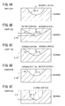
- the radius of curvature of the bearing surface was 2.0 mm. Accordingly, the ratio of the radius of curvature of the shaft end of the shaft with respect to the radius of curvature of the bearing surface was 75%.
- the depth of the bearing surface was 0.44 mm which was smaller than the radius of curvature (1.5 mm) of the shaft end of the shaft.
- a tapered portion was provided on the periphery of the bearing surface.
- the angles of the tapered portion in Samples B2 to B4 were respectively 25°, 33°, and 45°.
- Figs. 9A and 9B illustrate the experimental results related to the calorific values during rotations of the shaft, in each of the combinations (A to E) of the shafts and the bearings of which the radii of curvature are formed as shown in the following Table 2.
- Table 2 Combinations Radius of Curvature of Shaft End of Shaft (mm) Radius of Curvature of Bearing Surface (mm) Ratio of Radius of Curvature (%) A 1.25 1.5 Approximately 83 B 1.25 2.0 Approximately 63 C 1.5 1.5 100 D 1.5 2.0 75 E 1.5 2.5 60
- the room temperature was kept at 25°C.
- the gap between the shaft end 66 of the shaft 62 and the bearing surface 73 of the bearings 70 becomes suitable in size. Accordingly, it is possible to suppress hemolysis from occurring due to sliding between the shaft 62 and the bearings 70.
- the radius of curvature of the first shaft end 66A (or the second shaft end 66B) is set to be 1.5 mm and the radius of curvature of the bearing surface 73 of the first bearing 70A (or the second bearing 70B) is set to be 2.0 mm, it is possible to reliably suppress hemolysis from occurring due to sliding between the shaft 62 and the bearings 70.
- the tightening load in the axial direction with respect to the shaft 62 is set to range from 30 N to 60 N, together with the above-described hemolysis suppressing effect obtained by setting the radius of curvature, it is possible to more effectively suppress hemolysis from being formed, and it is possible to suppress formation of a thrombus and damage to the bonded portion (an occurrence of a crack, and the like) between the base 48 of the housing 26 and the cover 50.
- the ratio of the radius r1 of curvature of the first shaft end 66A with respect to the radius r2 of curvature of the bearing surface 73 of the first bearing 70A may be different from the ratio of the radius of curvature of the second shaft end 66B with respect to the radius of curvature of the bearing surface 73 of the second bearing 70B.
- any one between the ratio of the radius r1 of curvature of the first shaft end 66A with respect to the radius r2 of curvature of the bearing surface 73 of the first bearing 70A and the ratio of the radius of curvature of the second shaft end 66B with respect to the radius of curvature of the bearing surface 73 of the second bearing 70B may be equal to or less than 85%.
Landscapes
- Health & Medical Sciences (AREA)
- Engineering & Computer Science (AREA)
- Heart & Thoracic Surgery (AREA)
- Mechanical Engineering (AREA)
- General Health & Medical Sciences (AREA)
- Biomedical Technology (AREA)
- Hematology (AREA)
- Life Sciences & Earth Sciences (AREA)
- Animal Behavior & Ethology (AREA)
- Public Health (AREA)
- Veterinary Medicine (AREA)
- Anesthesiology (AREA)
- Cardiology (AREA)
- General Engineering & Computer Science (AREA)
- Urology & Nephrology (AREA)
- Emergency Medicine (AREA)
- Vascular Medicine (AREA)
- Physics & Mathematics (AREA)
- Geometry (AREA)
- Pulmonology (AREA)
- Structures Of Non-Positive Displacement Pumps (AREA)
- External Artificial Organs (AREA)
Abstract
Description
- The present invention relates to a centrifugal pump which delivers liquid such as blood and the like.
- During cardiac surgery, a heart-lung machine is adopted.
- The heart-lung machine is used by being embedded in an extracorporeal circulation circuit and performs oxygenation of blood drained from a patient, elimination of foreign bodies, and the like.
- As the heart-lung machine, there are various types depending on differences in the type of artificial lung, the type of pump, the position where the pump is disposed, and the like. A heart-lung machine generally includes a reservoir (for venous blood), an artificial lung, a heat exchanger, a pump, and a plurality of tubes for connecting the components (for example, refer to
JP-A-2009-160265 - As the pump adopted in the heart-lung machine, there is a centrifugal pump which delivers blood by utilizing centrifugal force occurring due to rotations of an impeller. Generally, the centrifugal pump includes a housing, the impeller which is rotatably disposed in the housing, a shaft which is provided at the center rotational axis of the impeller, and a bearing which rotatably supports the shaft. In regard to an advantage in which a thrombus (blood clot) can be prevented from occurring, there is a centrifugal pump in which a pivot bearing is used as the bearing.
- Incidentally, in a case of the centrifugal pumps in the related art employing the pivot bearing, in a state where a predetermined tightening load is applied to the shaft in the axial direction, the shaft is rotatably supported in the housing.
- In this case, when the tightening load is excessively small, oscillations during rotations of the shaft increase so that hemolysis (damage to blood corpuscles) is likely to occur. On the contrary, when the tightening load is excessively significant, a thrombus is likely to occur.
- Therefore, it is preferable that the tightening load applied to the shaft and the bearing is set within a proper range.
- Incidentally, over long-term use of the centrifugal pump, a load (tightening load) is continuously applied to the bearing and the housing. Therefore, there are cases where the depth of the recessed bearing surface of the bearing increases or the housing is warped.
- When a dimensional gap occurs between the members due to such deformation, the load applied to the shaft and the bearing is deviated from the proper predetermined range. Accordingly, oscillations (shaft shaking) during rotations of the shaft increase so that hemolysis is likely to occur.
- The present invention has been made in consideration of the foregoing problem, and an object thereof is to provide a centrifugal pump in which a load applied to a shaft and bearings over long-term use can be retained within a predetermined range.
- In order to achieve the object, according to the present invention, there is provided a centrifugal pump including a housing, an impeller that is rotatably disposed in the housing, a shaft that is provided at a center rotational axis of the impeller and has shaft ends at both ends thereof in an axial direction, and bearings that respectively and pivotally support the shaft ends. An elastic body which is elastically deformable at least in the axial direction of the shaft is provided between at least one of the bearings and the housing or at an intermediate portion of the shaft in the axial direction.
- According to the configuration of the present invention, the elastic body provided between the bearing and the housing or in the shaft causes a load applied to the shaft and the bearing to be retained within a predetermined range. Therefore, it is possible to stably and tightly maintain the shaft between the bearings over long-term use of the centrifugal pump.
- In other words, even though the bearing or the housing receiving a load is chronologically deformed, the elastic body absorbs a dimensional gap which can occur between the members due to deformation. Therefore, a load applied to the shaft and the bearing is retained within a predetermined range.
- Accordingly, oscillations of the shaft (shaft shaking) due to long-term use are prevented. Therefore, it is possible to effectively prevent an occurrence of hemolysis arising from the oscillations of the shaft.
- In the centrifugal pump, the elastic body may be disposed between the bearing and the housing.
- Accordingly, with a simple configuration, it is possible to absorb a dimensional gap occurring due to chronological deformation of the bearing or the housing.
- In the centrifugal pump, the elastic body may be disposed on a rear surface side of the impeller.
- A space is more likely to be provided on the rear surface side of the impeller than on the front surface side. Therefore, the elastic body can be easily disposed.
- In the centrifugal pump, the elastic body may have a side wall which surrounds an outer circumferential portion of the bearing.
- Accordingly, the bearing can be prevented from being deformed toward the impeller side. Therefore, it is possible to prevent the deformed bearing from adversely affecting the flow of blood in the housing and to prevent the bearing from interfering with the impeller.
- In the centrifugal pump, the elastic body may be made of silicone rubber.
- Accordingly, it is possible to more effectively absorb an error occurring due to chronological deformation of the bearing or the housing.
- According to the centrifugal pump of the present invention, it is possible to cause a load applied to the shaft and the bearings to be kept within a predetermined range over long-term use.
-
- [
Fig. 1] Fig. 1 is a schematic view of a heart-lung machine. - [
Fig. 2] Fig. 2 is a plan view of a centrifugal pump according to an embodiment of the present invention. - [
Fig. 3] Fig. 3 is a cross-sectional view taken along line III-III inFig. 2 . - [
Fig. 4] Fig. 4 is a cross-sectional view of a first bearing and a peripheral portion thereof. - [
Fig. 5] Fig. 5 is a graph illustrating a relationship between tightening loads and amounts of hemolysis. - [
Fig. 6] Fig. 6 is a cross-sectional view of a centrifugal pump according to a modification example. - [
Fig. 7] Fig. 7 is a graph illustrating relationships between surface roughness Ra and the amounts of hemolysis. - [
Fig. 8] Fig. 8A is a cross-sectional view of a bearing according to Sample B1,Fig. 8B is a cross-sectional view of a bearing according to Sample B2,Fig. 8C is a cross-sectional view of a bearing according to Sample B3,Fig. 8D is a cross-sectional view of a bearing according to Sample B4, andFig. 8E is a cross-sectional view of a bearing according to Sample B5. - [
Fig. 9] Fig. 9A is a graph illustrating an experimental result related to calorific values during rotations of a shaft, andFig. 9B is another graph illustrating the experimental result related to the calorific values during rotations of the shaft. - Hereinafter, description will be given regarding a favorable embodiment of a centrifugal pump of the present invention, with reference to the accompanying drawings.
-
Fig. 1 is a schematic view of a heart-lung machine 12 including acentrifugal pump 10 of the present invention. For example, the heart-lung machine 12 is used for cardiac surgery or the like. The heart-lung machine 12 performs oxygenation of blood removed from a patient, elimination of foreign bodies, and the like, thereby returning the blood to the patient. - As illustrated in
Fig. 1 , the heart-lung machine 12 includes areservoir 14, acentrifugal pump 10, apump driving unit 16, and anartificial lung 18. - The
reservoir 14 temporarily stores blood drained from a patient (venous blood). - The
reservoir 14 has a reservoirmain body 20, ablood inlet port 21 which is provided in an upper portion of the reservoirmain body 20 and is connected to avenous line 24 for delivering blood from a blood removing cannula inserted into a patient, and ablood outlet port 22 which is provided in a lower portion of the reservoirmain body 20 and is connected to thecentrifugal pump 10 via afirst connection line 23. - In the reservoir
main body 20, a blood filter (not illustrated) which filters blood flowing in via theblood inlet port 21 is disposed. - Note that, the reservoir
main body 20 is also provided with an inlet port (not illustrated) which is connected to a cardiotomy line for delivering blood from the surgical field of a patient. - The
centrifugal pump 10 delivers blood from thereservoir 14 to theartificial lung 18. - The
centrifugal pump 10 includes at least ahousing 26 and animpeller 28 which is rotatably disposed in thehousing 26. - The
housing 26 has ablood inlet port 30 which is connected to theblood outlet port 22 of thereservoir 14 via thefirst connection line 23, and ablood outlet port 32 which is connected to theartificial lung 18 via asecond connection line 33. - For example, the
first connection line 23 and thesecond connection line 33 are flexible and transparent tubes. - Blood flowed into a central portion of the
impeller 28 through theblood inlet port 30 flows to an outer circumferential side of theimpeller 28 while being accelerated in accordance with rotations of theimpeller 28, thereby being discharged through theblood outlet port 32. Note that, the detailed structure of thecentrifugal pump 10 will be described later. - The
pump driving unit 16 has amotor 36, a rotary member 37 (for example, a rotary plate) which is fixed to arotary shaft 36a of themotor 36,permanent magnets 38 which are attached to therotary member 37, and acase 40 which accommodates these components. - It is favorable that a plurality of the
permanent magnets 38 are provided at substantially equal intervals in the circumferential direction centering around therotary shaft 36a of themotor 36. For example, thepermanent magnets 38 are provided as many as the number of the below-describedpermanent magnets 86 provided in thecentrifugal pump 10. - Due to the above-described configuration of the
pump driving unit 16, thepermanent magnets 38 provided in thepump driving unit 16 magnetically attract thepermanent magnets 86 provided in thecentrifugal pump 10. - When the
motor 36 rotates in such a magnetically attracted state, thepermanent magnets 38 rotate together with themotor 36, and theimpeller 28 also rotates along with the rotations thereof. - Note that, both an AC motor and a DC motor may be used as the
motor 36. It is favorable to use a variable speed motor. - For example, when a stepping motor is used as the
motor 36, it is easy to control the flow rate of blood in thecentrifugal pump 10. - The heart-
lung machine 12 includes acontrol unit 45, and thecontrol unit 45 controls driving of themotor 36. In thecentrifugal pump 10 which is driven as described above, for example, theimpeller 28 can rotate within a range from 0 rpm to 3,000 rpm. - When the rotational frequency of the
impeller 28 is equal to or less than 3,000 rpm, it is likely to suppress hemolysis and a thrombus from being formed. - Note that, the
impeller 28 may be able to rotate equal to or higher than 3,000 rpm. - The
artificial lung 18 has amain body 41, ablood inlet port 42 which is connected to theblood outlet port 32 of thecentrifugal pump 10 via thesecond connection line 33, and ablood outlet port 43 which is connected to aretransfusion line 44 for returning blood to a patient. - The
main body 41 adds oxygen to blood flowing in via theblood inlet port 42 and performs gas exchange for eliminating carbon dioxide. - Note that, the
artificial lung 18 also has a function of heat exchange for changing a blood temperature. -
Fig. 2 is a plan view of thecentrifugal pump 10.Fig. 3 is a cross-sectional view taken along line III-III inFig. 2 . - As illustrated in
Figs. 2 and3 , thehousing 26 in thecentrifugal pump 10 has a base 48 configuring a lower portion, and acover 50 configuring an upper portion. - The
base 48 and thecover 50 form aspace 26a (hereinafter, referred to as "theaccommodation space 26a") in which theimpeller 28 is internally accommodated. - The
base 48 has a substantial disk shape in its entirety. As illustrated inFig. 3 , thebase 48 has acircular floor 51 and acircumferential wall 52 which protrudes upward from the outer circumferential portion of thefloor 51 and continuously encircles the circumference in the circumferential direction. - A central portion of the
floor 51 is provided with a recessedfirst disposition portion 54. - The
cover 50 has a disk-shapedceiling 56 and acircumferential wall 57 which protrudes downward from the outer circumference of theceiling 56 and continuously encircles the circumference in the circumferential direction. - The lower end of the
circumferential wall 57 of thecover 50 and the upper end of thecircumferential wall 52 of the base 48 are in a state of being fitted with each other and are fixed to each other by appropriate bonding means such as an adhesive and the like. - Note that, in
Fig. 3 , the lower end of thecircumferential wall 57 of thecover 50 is fitted with the inner side of the upper end of thecircumferential wall 52 of thebase 48. Alternatively, the upper end of thecircumferential wall 52 of the base 48 may be fitted with the inner side of the lower end of thecircumferential wall 57 of thecover 50. - The
cover 50 is provided with a protrudingcylinder portion 58 which protrudes upward from the center of theceiling 56. - The protruding
cylinder portion 58 is configured to have a hollow open-bottom structure in which the upper end is closed. - Inside an upper portion of the protruding
cylinder portion 58, a recessedsecond disposition portion 60 is provided. - In addition, the
cover 50 is provided with the above-describedblood inlet port 30. - In the present embodiment, the
blood inlet port 30 extends from the protrudingcylinder portion 58 in a direction intersecting the protruding cylinder portion 58 (in the illustrated example, in an inclination direction). - A
lumen 30a of theblood inlet port 30 communicates with theaccommodation space 26a via alumen 58a of the protrudingcylinder portion 58. - The
cover 50 is also provided with the above-describedblood outlet port 32. - In the present embodiment, the
blood outlet port 32 extends from the outer side surface of thecircumferential wall 57 of thecover 50 in a tangential direction. - A
lumen 32a of theblood outlet port 32 communicates with theaccommodation space 26a. - As a configuration material of the housing 26 (the
base 48 and the cover 50), for example, it is possible to exemplify various types of resin materials such as various types of glass; polyvinyl chloride; polyethylene; polypropylene; cyclic polyolefin; polystyrene; poly-(4-methylpentene-1); polycarbonate; an acrylic resin; an acrylonitrile-butadiene-styrene copolymer; polyester such as polyethylene terephthalate, polyethylene naphthalate, and the like; a butadiene-styrene copolymer; polyamide (for example, nylon 6, nylon 6,6,nylon 6,10, nylon 12); and the like. - It is favorable that the
housing 26 is made of a transparent material so that blood flowing in thehousing 26 can be visually recognized. - In the
impeller 28, a plurality ofblood induction paths 84 which radially extend from a substantial center of theimpeller 28 toward the outer circumferential side are provided. - In addition, inside the
impeller 28, a plurality of thepermanent magnets 86 for transmitting rotating force to theimpeller 28 from the outside are provided at intervals in the circumferential direction. - The
blood induction paths 84 are not limited to being straight as illustrated inFig. 2 and may have curved shapes. - The outer diameter of the
impeller 28 is not particularly limited. For example, the outer diameter can be set to range approximately from 50 mm to 100 mm. - As the outer diameter of the
impeller 28 becomes greater, it is more likely to generate high discharge pressure. - For example, when the outer diameter of the
impeller 28 is equal to or greater than 70 mm, even though the maximum rotational frequency is approximately 3,000 rpm, it is possible to generate comparatively high discharge pressure. As described above, in a case where the rotational frequency is equal to or less than 3,000 rpm, it is likely to prevent hemolysis and a thrombus from being formed. - Therefore, when the outer diameter is equal to or greater than 70 mm and the maximum rotational frequency is equal to or lower than 3,000 rpm, while suppressing hemolysis and a thrombus from being formed, the
impeller 28 can generate comparatively high discharge pressure. - In the present embodiment, the
impeller 28 has afirst rotor 87 which is configured to form the bottom portion, asecond rotor 88 which concentrically overlaps thefirst rotor 87 from above, and arotor cover 89 which concentrically overlaps thesecond rotor 88 from above. - The plurality of above-described
permanent magnets 86 are respectively held by a plurality ofmagnet holding portions 90 which are provided on the top surface of thefirst rotor 87. - The plurality of above-described
blood induction paths 84 are formed between thesecond rotor 88 and therotor cover 89. - A plurality of flow
channel forming walls 91 which protrude downward from the bottom surface of therotor cover 89 are configured to form both side walls of theblood induction paths 84. - The top surface of the
rotor cover 89 has a conical shape, and anopening 92 is formed in a central portion thereof. - A
shaft 62 is provided in the central portion of theimpeller 28. - The
shaft 62 is a straight rod-shaped member and has spherical surface-shaped shaft ends 66 at both ends in an axial direction. - The
shaft 62 is fixed to theimpeller 28 in a state of being inserted into theinsertion hole 63 penetrating the central portion of theimpeller 28 in the axial direction. - The
shaft 62 and theimpeller 28 cannot relatively rotate and are fixed to each other in a state of not being able to be relatively displaced in the axial direction. - In the present embodiment, a
projection 65 which is provided on the inner circumferential wall forming theinsertion hole 63 of theimpeller 28 engages with agroove 64 which is provided in theshaft 62. Thus, theshaft 62 and theimpeller 28 are fixed to each other. - Both ends of the
shaft 62 respectively protrude downward and upward from theimpeller 28. - Hereinafter, in a case of discriminating the two shaft ends 66 from each other, the
shaft end 66 on the lower side is referred to as "thefirst shaft end 66A" and theshaft end 66 on the upper side is referred to as "thesecond shaft end 66B". - For example, the configuration material of the
shaft 62 can be selected from the materials exemplified above as the configuration material of thehousing 26. - For example, it is favorable that the
shaft 62 is to be formed from a ceramic-based material such as alumina ceramic and the like being excellent in abrasion resistance and sliding properties and being advantageous to suppress an occurrence of hemolysis and formation of a thrombus. - The
centrifugal pump 10 also includesbearings 70 which are provided on both end sides of theshaft 62 and respectively and pivotally support the shaft ends 66. Hereinafter, in a case of discriminating the twobearings 70 from each other, the bearing on the lower side, that is, the bearing pivotally supporting thefirst shaft end 66A is referred to as "thefirst bearing 70A", and the bearing on the upper side, that is, the bearing pivotally supporting thesecond shaft end 66B is referred to as "thesecond bearing 70B". - In other words, the
first bearing 70A and thesecond bearing 70B are configured to be pivot bearings. - The
shaft 62 is rotatably held between thefirst bearing 70A and thesecond bearing 70B in a state where a predetermined tightening load is applied in the axial direction in thehousing 26. - In a case where the tightening load is excessively small (for example, in a case of being smaller than 30 N), oscillations during rotations of the
shaft 62 increase so that hemolysis is likely to occur. -
Fig. 5 is a graph illustrating relationships between the tightening loads and amounts of hemolysis, obtained through a test. - As seen from
Fig. 5 , in a case where the tightening load is less than 30 N, compared to a case of being equal to or more than 30 N, it is ascertained that the amount of hemolysis increases remarkably. - On the contrary, in a case where the tightening load with respect to the
shaft 62 is excessively significant (for example, in a case of exceeding 60 N), a thrombus is likely to occur, and there is a possibility of damage to a bonded portion between the base 48 of thehousing 26 and thecover 50. - Therefore, it is preferable that the tightening load applied to the
shaft 62 is set within a proper range (for example, approximately from 30 N to 60 N) when manufacturing thecentrifugal pump 10. - As illustrated in
Fig. 3 , thefirst bearing 70A has a bearingsurface 73 which is recessed so as to have a spherical surface shape. - The bearing
surface 73 of thefirst bearing 70A abuts against thefirst shaft end 66A. - A radius r2 of curvature of the bearing
surface 73 of thefirst bearing 70A is greater than a radius r1 of curvature of the first shaft end 66A (refer toFig. 4 ). - An
elastic body 80 which is elastically deformable at least in the axial direction of theshaft 62 is disposed between the bearing 70 (thefirst bearing 70A in the illustrated example) and the housing 26 (the base 48 in the illustrated example). - The
elastic body 80 is disposed (mounted) in the recessedfirst disposition portion 54 formed in thebase 48, on the rear surface side of theimpeller 28. - The
elastic body 80 disposed as described above elastically supports thefirst bearing 70A. - In other words, in a state where a predetermined tightening load is applied to the
shaft 62 in thehousing 26 and theshaft 62 is supported by thefirst bearing 70A and thesecond bearing 70B therebetween, theelastic body 80 is held in an elastic compression state between thefirst bearing 70A and the housing 26 (the base 48). - In the case of the present embodiment, as illustrated in
Fig. 4 , theelastic body 80 includes abase portion 81 and aside wall 82. Thebase portion 81 is clamped between the rear surface side (the opposite side of the bearing surface 73) of thefirst bearing 70A and the housing 26 (the base 48). Thebase portion 81 supports the rear surface side of thefirst bearing 70A. Theside wall 82 which perpendicularly protrudes from an outer end of thebase portion 81 and surrounds the outer circumferential portion of thefirst bearing 70A. - The
first bearing 70A which is disposed at a recessedportion 83 formed by thebase portion 81 and theside wall 82 is elastically supported in the axial direction by thebase portion 81 of theelastic body 80 and is elastically supported in a radial direction by theside wall 82 of theelastic body 80. - Note that, the
side wall 82 may be formed so as to continuously encircle the circumference in the circumferential direction, and a plurality thereof may be formed at substantially equal intervals in the circumferential direction. - In the case of the present embodiment, the
elastic body 80 is made of a material having elasticity itself. - As the material thereof, without being particularly limited, for example, it is possible to exemplify various types of rubber materials such as natural rubber, butyl rubber, isoprene rubber, butadiene rubber, styrene-butadiene rubber, and silicone rubber; various types of thermoplastic elastomers such as a polyurethane-based elastomer, a polyester-based elastomer, a polyamide-based elastomer, an olefin-based elastomer, a styrene-based elastomer, and the like; and a mixture thereof.
- Among thereof, for example, silicone rubber can effectively absorb the below-described error occurring due to chronological deformation of the
bearing 70 or thehousing 26. Therefore, it is favorable to use silicone rubber as the material of theelastic body 80. - As illustrated in
Fig. 3 , thesecond bearing 70B has adifferent bearing surface 73 which is recessed so as to have a spherical surface shape. - The bearing
surface 73 of thesecond bearing 70B abuts against thesecond shaft end 66B, and the radius of curvature thereof is greater than the radius of curvature of thesecond shaft end 66B. - The radius of curvature of the
second shaft end 66B may be the same as or different from the radius r1 of curvature (refer toFig. 4 ) of thefirst shaft end 66A. - The radius of curvature of the bearing
surface 73 of thesecond bearing 70B may be the same as or different from the radius r2 of curvature (refer toFig. 4 ) of the bearingsurface 73 of thefirst bearing 70A. - The
second bearing 70B is disposed in the recessedsecond disposition portion 60 which is provided in the protrudingcylinder portion 58 of thecover 50. - For example, the configuration material of the
bearings 70 can be selected from the materials exemplified above as the configuration material of thehousing 26. - It is favorable that the configuration material of the
bearings 70 is made of polyethylene having an ultra-high molecular weight and being excellent in abrasion resistance and self-lubrication properties. - In the
centrifugal pump 10 having the above-described configuration, when blood flows into thehousing 26 via theblood inlet port 30, the blood flows into theimpeller 28 through theopening 92 provided at the apex portion of theimpeller 28, thereby being scattered. - Centrifugal force is applied to the scattered blood due to rotations of the
impeller 28 so that the blood flows in theblood induction paths 84 toward the outer circumferential side of theimpeller 28. - The blood flowing out from the
blood induction paths 84 flows between the outer side surface of theimpeller 28 and the inner side surface of thehousing 26. Thereafter, the blood flows out through theblood outlet port 32. - The
centrifugal pump 10 according to the present embodiment basically has a configuration as described above. Hereinafter, an operation and an effect thereof will be described. - As described above, in the
centrifugal pump 10 according to the present embodiment, theelastic body 80 which is elastically deformable in the axial direction of theshaft 62 is provided. - According to such a configuration, the
elastic body 80 causes a load applied to theshaft 62 and thebearings 70 to be retained within a predetermined range. Therefore, it is possible to stably and tightly maintain theshaft 62 between thebearings 70 over long-term use of thecentrifugal pump 10. - In other words, even though the
bearing 70 or thehousing 26 receiving a load is chronologically deformed, theelastic body 80 absorbs a dimensional gap which can occur between the members due to deformation. Therefore, a load applied to theshaft 62 and thebearing 70 is retained within a predetermined range. - Accordingly, oscillations of the shaft 62 (shaft shaking) due to long-term use are suppressed. Therefore, it is possible to effectively suppress an occurrence of hemolysis arising from the oscillations of the
shaft 62. - Particularly, in the case of the present embodiment, the
elastic body 80 is disposed between the bearing 70 and thehousing 26. Therefore, with a simple configuration, it is possible to absorb a dimensional gap occurring due to chronological deformation of thebearing 70 or thehousing 26. - In addition, as seen from
Fig. 3 , in a case where theelastic body 80 is disposed on the rear surface side of the impeller 28 (that is, thefirst bearing 70A side), a space is more likely to be provided on the rear surface side of theimpeller 28 than on the front surface side. Therefore, theelastic body 80 can be easily disposed. - Note that, the
elastic body 80 may be disposed on the front surface side of the impeller 28 (that is, thesecond bearing 70B side), and theelastic body 80 may be disposed on both the rear surface side and the front surface side of theimpeller 28. - In this case, the
elastic body 80 which is disposed on the front surface side of theimpeller 28 is disposed between thesecond bearing 70B and the cover 50 (the protrudingcylinder portion 58 inFig. 3 ) of thehousing 26, thereby elastically supporting thesecond bearing 70B. - Moreover, in the case of the present embodiment, as illustrated in
Fig. 4 , theelastic body 80 has theside wall 82 surrounding the outer circumferential portion of thebearing 70. Therefore, it is possible to prevent the bearing 70 from being deformed toward theimpeller 28 side. In other words, in a case where the outer circumferential portion of thebearing 70 is surrounded by a hard wall replacing theside wall 82, as indicated by the virtual line inFig. 4 , in accordance with thebearing 70 being chronologically deformed in a direction in which a recess of the bearingsurface 73 becomes greater, there is a possibility that the volume integral of the deformed portion protrudes toward theimpeller 28 side. - In contrast, in a case where the
elastic body 80 is provided with theside wall 82, in accordance with deformation in the direction in which the recess of the bearingsurface 73 becomes greater, theside wall 82 absorbs the radially outward deformation of thebearing 70. - Therefore, it is possible to prevent the
deformed bearing 70 from adversely affecting the flow of blood in thehousing 26 and to prevent the bearing 70 from interfering with theimpeller 28. - In the above-described
centrifugal pump 10, theelastic body 80 is provided between any one or both of thefirst bearing 70A and thesecond bearing 70B, and thehousing 26. However, as in acentrifugal pump 10a according to a modification example illustrated inFig. 6 , anelastic body 94 may be provided at an intermediate portion of theshaft 62 in the axial direction. - In this case, the
shaft 62 includes afirst shaft portion 62a and asecond shaft portion 62b which respectively have the first shaft end 66A and thesecond shaft end 66B and are made of a hard material, and theelastic body 94 which is provided between thefirst shaft portion 62a and thesecond shaft portion 62b. - The
elastic body 94 is interposed between thefirst shaft portion 62a and thesecond shaft portion 62b in an elastic compression state. - The configuration material of the
elastic body 94 can be selected from the materials exemplified above as the configuration material of theelastic body 80. - In addition, the
first shaft portion 62a is fixed to theimpeller 28, and thesecond shaft portion 62b is not fixed. - Therefore, the
second shaft portion 62b can move in the axial direction as much distance as the deformation of theelastic body 94. - In this case, it is preferable that a joint portion between the
second shaft portion 62b and theelastic body 94 is located inside the impeller 28 (in other words, it is preferable that theelastic body 94 is disposed so as not to be exposed from the impeller 28). - Moreover, even in a case where the
second shaft portion 62b moves in the axial direction as much distance as the deformation of theelastic body 94, it is preferable that the joint portion between thesecond shaft portion 62b and theelastic body 94 is located inside theimpeller 28 so that at least a portion of thesecond shaft portion 62b is held at all times by a lumen provided at the center of the impeller 28 (in other words, even in a case of being deformed in the axial direction as much distance as a length released from an elastic compression state, it is preferable that theelastic body 94 is disposed so as not to be exposed from the impeller 28). - Accordingly, it is possible to suppress the possibility of disconnection or folding of the
shaft 62 occurring due to stress concentration and the like at the joint portion between thesecond shaft portion 62b and theelastic body 94. - In addition, since the
second shaft portion 62b is not fixed to theimpeller 28, there is a possibility of an occurrence of torsion starting from theelastic body 94. Therefore, it is more preferable to have a torsion prevention mechanism (not illustrated) as a prevention measure thereof, for example, forming a slit in the axial direction of thesecond shaft portion 62b, causing theimpeller 28 to be provided with a projection portion which is fitted with the slit of thesecond shaft portion 62b, and the like for restricting rotations while not restricting movement in the axial direction. - According to the configuration of the
centrifugal pump 10a as well, similar to the above-describedcentrifugal pump 10, theelastic body 94 provided at the intermediate portion of theshaft 62 in the axial direction causes a load applied to theshaft 62 and thebearing 70 to be retained within a predetermined range. Therefore, it is possible to stably and tightly maintain theshaft 62 between thebearings 70 over long-term use of thecentrifugal pump 10a. Accordingly, oscillations of the shaft 62 (shaft shaking) due to long-term use are suppressed. Therefore, it is possible to effectively suppress an occurrence of hemolysis arising from the oscillations of theshaft 62. - Note that, in the
centrifugal pump 10 and thecentrifugal pump 10a, theelastic bodies elastic bodies - In the
centrifugal pump 10, thecentrifugal pump 10a, and the modification example thereof, the shaft ends 66 may be set to have surface roughness Ra (arithmetic average roughness) equal to or less than 0.21 µm, or the shaft ends 66 may be set to have surface roughness Ry (maximum height) equal to or less than 1.49 µm. - In a case of such a configuration, it is possible to further suppress hemolysis from occurring due to sliding between the
shaft 62 and thebearing 70, and it is possible to suppress a thrombus from being formed at the shaft ends 66 of theshaft 62. - Each of the shaft ends 66 may be set to have the surface roughness Ra equal to or less than 0.21 µm or the surface roughness Ry equal to or less than 1.49 µm.
- In order to check a hemolysis suppressing effect and a thrombus suppressing effect obtained by setting the surface roughness, two types of tests (a test related to an occurrence of hemolysis and a test related to formation of a thrombus) have been executed.
- In each test, the test was performed while having the shafts of Samples A1 to A5 as targets in which the surface roughness Ra and the surface roughness Ry of the shaft end were formed as those in Table 1.
- Note that, the surface roughness was measured by using a stylus-type surface roughness measuring machine (manufactured by Mitutoyo Corporation).
[Table 1] Surface Roughness Ra Surface Roughness Ry Amount of Hemolysis Formation of Thrombus Sample A1 0.05 0.28 Small No Sample A2 0.18 1.31 Small No Sample A3 0.21 1.49 Small No Sample A4 0.30 2.04 Great Present Sample A5 0.44 2.97 Great Present - In the test related to an occurrence of hemolysis, while circulating 2.0 L of blood at a flow rate of 8.0 L per minute by using a centrifugal pump in which the test target shafts were applied, the shaft (and the impeller) was continuously rotated for six hours at a rotational frequency of 2,600 rpm.
- The blood temperature was controlled so as to be at 37°C.
-
Fig. 7 is a graph illustrating the test result related to an occurrence of hemolysis (relationships between the surface roughness Ra and amounts of hemolysis). - As seen from
Fig. 7 , it is ascertained that as the surface roughness Ra of the shaft end of the shaft becomes smaller, the amount of hemolysis decreases (also refer to the column of "Amount of Hemolysis" in Table 1). - In this manner, in Samples A1 to A3, compared to Samples A4 and A5, it was confirmed that the amount of hemolysis decreased.
- Note that, since the surface roughness Ra and the surface roughness Ry have a constant correspondence relationship, it is possible to mention that as the surface roughness Ry becomes smaller, the amount of hemolysis decreases.
- In the test related to formation of a thrombus, 3 mL (heparin final concentration: 0.5 unit/mL) of blood and the test target shaft were caused to sink in a centrifugation tube, and the centrifugation tube was rotated about the central axial line of the centrifugation tube for six hours at room temperature at a predetermined speed, in a state where the centrifugation tube was laid sideways.
- Thereafter, the presence and the absence, and the degree of a thrombus formed at the shaft end of the shaft were checked.
- As a result of the test, in Sample A1 (Ra = 0.05 µm), almost no adhering blood component (platelet or the like) was found and no thrombus was confirmed.
- In each of Sample A2 (Ra = 0.18 µm) and Sample A3 (Ra = 0.21 µm), it was confirmed that a thin net-like film was slightly formed at the shaft end.
- Note that, the thin net-like film confirmed in Samples A2 and A3 was not a substance which might be referred to as a fibrin net (fibrin which is a fiber component in blood and is bonded in a mesh pattern), and no thrombus was confirmed. Therefore, it is understood that, in Samples A1 to A3, there is an effect of suppressing a thrombus from being formed (also refer to the column of "Formation of Thrombus" in Table 1).
- Meanwhile, in Sample A4 (Ra = 0.30 µm), it was confirmed that a thin fibrin net was formed at the shaft end.
- In Sample A5 (Ra = 0.44 µm), it was confirmed that a thick fibrin net was formed at the shaft end.
- A thrombus is formed due to blood corpuscles or platelets which become entangled with a fibrin net. Therefore, it is understood that, in Samples A4 and A5, there is no effect of suppressing a thrombus from being formed.
- According to the test result hereinbefore, it is ascertained that when the surface roughness Ra of the shaft end of the shaft is equal to or less than 0.21 µm, there is an effect of suppressing a thrombus from being formed, and as the surface roughness Ra becomes smaller, there is a high effect of suppressing a thrombus from being formed.
- Note that, since the surface roughness Ra and the surface roughness Ry have a constant correspondence relationship, it is possible to mention that as the surface roughness Ry becomes smaller, there is a high effect of suppressing a thrombus from being formed.
- As it is understood from above, in a case where the surface roughness Ra of the
shaft end 66 of theshaft 62 is equal to or less than 0.21 µm (the surface roughness Ry is equal to or less than 1.49 µm), it is possible to suppress hemolysis from occurring due to sliding between theshaft 62 and thebearing 70, and it is possible to suppress a thrombus from being formed at the shaft ends 66 of theshaft 62. - Particularly, when the surface roughness Ra of the
shaft end 66 is equal to or less than 0.21 µm and the surface roughness Ry of theshaft end 66 is equal to or less than 1.49 µm, an effect of suppressing an occurrence of hemolysis and formation of a thrombus is more favorably achieved. - In the
centrifugal pump 10 which employs the pivot bearings (the bearings 70) as means for supporting rotations of theshaft 62, the rotations of theshaft 62 are considered to be a cause of damage to blood. Therefore, controlling the surface roughness of theshaft end 66 of theshaft 62 leads to controlling of damage to blood. - It is considered that formation of a thrombus or an occurrence of hemolysis arising from rotations of the
shaft 62 occurs due to ground blood corpuscles, heat generation, shearing stress, and the like caused by friction between theshaft 62 and thebearing 70. - It is possible to effectively exclude the above-described factors of formation of a thrombus or an occurrence of hemolysis by setting the surface roughness of the
shaft end 66 of theshaft 62 within the above-referenced range. - In addition, in each of the first shaft end 66A and the
second shaft end 66B, in a case where the surface roughness Ra is equal to or less than 0.21 µm (the surface roughness Ry is equal to or less than 1.49 µm), it is possible to suppress an occurrence of hemolysis and formation of a thrombus at both ends of theshaft 62. Therefore, it is possible to further enhance a hemolysis prevention effect and a thrombus prevention effect. - In addition, in a case where the
shaft 62 is made of alumina ceramic, together with a hemolysis suppressing effect and a thrombus suppressing effect described above and obtained by setting the surface roughness Ra or the surface roughness Ry of theshaft end 66 of theshaft 62, it is possible to more effectively suppress hemolysis from occurring and to prevent a thrombus from being formed. - Note that, the surface roughness Ra or the surface roughness Ry of only one between the first shaft end 66A and the
second shaft end 66B may be set within the above-referenced range. - In this case, in any one between the first shaft end 66A and the
second shaft end 66B, it is possible to obtain a hemolysis suppressing effect and a thrombus suppressing effect described above. - In the
centrifugal pump 10, thecentrifugal pump 10a, and the modification example thereof, both the ratio of the radius r1 of curvature of thefirst shaft end 66A with respect to the radius r2 of curvature of the bearingsurface 73 of thefirst bearing 70A and the ratio of the radius of curvature of thesecond shaft end 66B with respect to the radius of curvature of the bearingsurface 73 of thesecond bearing 70B may be set to equal to or less than 85% or equal to or less than 75%. - In a case of such a configuration, gaps between the shaft ends 66 of the
shaft 62 and the bearing surfaces 73 of thebearings 70 become suitable in size. Therefore, it is possible to suppress hemolysis from occurring due to sliding between theshaft 62 and thebearings 70. - In order to check a hemolysis suppressing effect obtained by setting the ratio of the radius of curvature, a test has been executed.
- In the test, in 15 mL of blood put in a container, while the shaft was pressed with a load of 40 N with respect to each of the bearings respectively corresponding to Samples B1 to B5 illustrated in
Figs. 8A to 8E , the shaft was continuously rotated for an hour at a rotational frequency of 3,000 rpm. In all the shafts used in the experiments, the outer diameter was 3.0 mm and the radius of curvature of the shaft end was 1.5 mm. - As illustrated in
Fig. 8A , in the bearing of Sample B1, the radius of curvature of the bearing surface was 2.0 mm. Accordingly, the ratio of the radius of curvature of the shaft end of the shaft with respect to the radius of curvature of the bearing surface was 75%. - As illustrated in
Figs. 8B to 8E , in the bearings of Samples B2 to B5, the radius of curvature of the bearing surface was 1.5 mm. Accordingly, the ratio of the radius of curvature of the shaft end of the shaft with respect to the radius of curvature of the bearing surface was 100%. - Note that, in Samples B2 to B4, the depth of the bearing surface was 0.44 mm which was smaller than the radius of curvature (1.5 mm) of the shaft end of the shaft. A tapered portion was provided on the periphery of the bearing surface.
- The angles of the tapered portion in Samples B2 to B4 were respectively 25°, 33°, and 45°.
- In addition, in Sample B5, the depth of the bearing surface was 2.0 mm which was greater than the radius of curvature of the shaft end of the shaft.
- As a result of the test performed under the above-described conditions, hemolysis was effectively suppressed in Sample B1. Therefore, compared to Samples B2 to B5, it was confirmed that the amount of hemolysis was drastically small.
- It is considered that such a suppressing effect of hemolysis is achieved due to the gap retained in a suitably wide manner between the shaft end of the shaft and the bearing surface of the bearing.
- Meanwhile, in Samples B2 to B4, as the angle of the tapered portion became smaller, that is, as the gap between the shaft and the bearing became greater, it was confirmed that the amount of hemolysis decreased. Nevertheless, the amount of hemolysis was greater than that of Example, and no particularly meaningful effect in terms of suppression of hemolysis suppression was observed.
- In Sample B5, it was confirmed that the amount of hemolysis increased remarkably.
- Regarding the case of Sample B5, it is considered to be caused by the fact that the bearing surface in its entirety contacts the shaft.
-
Figs. 9A and 9B illustrate the experimental results related to the calorific values during rotations of the shaft, in each of the combinations (A to E) of the shafts and the bearings of which the radii of curvature are formed as shown in the following Table 2.[Table 2] Combinations Radius of Curvature of Shaft End of Shaft (mm) Radius of Curvature of Bearing Surface (mm) Ratio of Radius of Curvature (%) A 1.25 1.5 Approximately 83 B 1.25 2.0 Approximately 63 C 1.5 1.5 100 D 1.5 2.0 75 E 1.5 2.5 60 - In this test, in 9 mL of fluid volume of water, while the shaft was pressed with a load of approximately 52 N (5.3 kgf) with respect to the bearing, the shaft was continuously rotated for a predetermined period of time at a rotational frequency of 2,500 rpm, and the temperature rise of water was measured.
- The room temperature was kept at 25°C.
- Note that, in Table 2, "Ratio of Radius of Curvature (%)" denotes the ratio (%) of the radius of curvature of the shaft end of the shaft with respect to the radius of curvature of the bearing surface.
- As illustrated in
Figs. 9A and 9B , in the combination C, the temperature rise due to the elapse of time was significant, that is, the calorific value was great. In the combinations A, B, D, and E, compared to the combination C, a result of a gentle temperature rise due to the elapse of time, that is, a small calorific value was obtained. Incidentally, the combination C having a great calorific value corresponds to Sample B5 ofFig. 8E , and the combination D having a small calorific value corresponds to Sample B1 ofFig. 8A . - From the above-referenced fact, it is considered that formation of hemolysis is greatly influenced by heat generation.
- According to the test results thereof, in a case where the ratio of the radius of curvature of the shaft end of the shaft with respect to the radius of curvature of the bearing surface ranges from 60% to approximately 83%, it is ascertained that heat generation can be suppressed and a hemolysis suppressing effect can be obtained.
- In addition, from the fact that almost no difference was recognized between the calorific values (temperature rises) through the comparison between the ratio of 75% (combination D) and the ratio of approximately 83% (combination A), it is considered that even though the ratio is approximately 85%, a hemolysis suppressing effect can be obtained.
- Note that, another experiment was performed so as to measure the amount of hemolysis with the combination of a flat bearing surface and a spherical surface-shaped shaft end, and the calorific value became the least in a case of this combination.
- From the above-referenced fact, even in a case where the ratio is less than 60%, it is ascertained that a hemolysis prevention effect can be obtained.
- As it has been understood from the above-described fact, according to the present invention, when a relationship between the radius of curvature of the
shaft end 66 of theshaft 62 and the radius of curvature of the bearingsurface 73 of the bearings 70 (the ratio of the radius of curvature of theshaft end 66 with respect to the radius of curvature of the bearing surface 73) is set within a predetermined range (equal to or less than 85%), the gap between theshaft end 66 of theshaft 62 and the bearingsurface 73 of thebearings 70 becomes suitable in size. Accordingly, it is possible to suppress hemolysis from occurring due to sliding between theshaft 62 and thebearings 70. - In addition, with reference to the experimental results, in addition to setting of the ratio related to the radius of curvature, when the radius of curvature of the
shaft end 66 is set to range from 1.25 mm to 1.5 mm, or the radius of curvature of the bearingsurface 73 is set to range from 1.5 mm to 2.5 mm, it is possible to effectively suppress hemolysis from occurring due to sliding between theshaft 62 and thebearings 70. - In addition, as is clear from the experimental results, when the radius of curvature of the first shaft end 66A (or the
second shaft end 66B) is set to be 1.5 mm and the radius of curvature of the bearingsurface 73 of thefirst bearing 70A (or thesecond bearing 70B) is set to be 2.0 mm, it is possible to reliably suppress hemolysis from occurring due to sliding between theshaft 62 and thebearings 70. - In addition, when the tightening load in the axial direction with respect to the
shaft 62 is set to range from 30 N to 60 N, together with the above-described hemolysis suppressing effect obtained by setting the radius of curvature, it is possible to more effectively suppress hemolysis from being formed, and it is possible to suppress formation of a thrombus and damage to the bonded portion (an occurrence of a crack, and the like) between the base 48 of thehousing 26 and thecover 50. - Note that, the ratio of the radius r1 of curvature of the
first shaft end 66A with respect to the radius r2 of curvature of the bearingsurface 73 of thefirst bearing 70A may be different from the ratio of the radius of curvature of thesecond shaft end 66B with respect to the radius of curvature of the bearingsurface 73 of thesecond bearing 70B. - Therefore, for example, any one between the ratio of the radius r1 of curvature of the
first shaft end 66A with respect to the radius r2 of curvature of the bearingsurface 73 of thefirst bearing 70A and the ratio of the radius of curvature of thesecond shaft end 66B with respect to the radius of curvature of the bearingsurface 73 of thesecond bearing 70B may be equal to or less than 85%. - In this case as well, a hemolysis suppressing effect can be obtained.
- In the above description, a favorable embodiment of the present invention has been exemplified. However, the present invention is not limited to the embodiment, and it is not necessary to mention that various modifications and changes can be made without departing from the scope of the present invention.
Claims (5)
- A centrifugal pump (10, 10a) comprising:a housing (26);an impeller (28) that is rotatably disposed in the housing (26);a shaft (62) that is provided at a center rotational axis of the impeller (28) and has shaft ends (66) at both ends thereof in an axial direction; andbearings (70) that respectively and pivotally support the shaft ends (66),wherein an elastic body (80, 94) which is elastically deformable at least in the axial direction of the shaft (62) is provided between at least one of the bearings (70) and the housing (26) or at an intermediate portion of the shaft (62) in the axial direction.
- The centrifugal pump (10) according to Claim 1,
wherein the elastic body (80) is disposed between the bearing (70) and the housing (26). - The centrifugal pump (10) according to Claim 2,
wherein the elastic body (80) is disposed on a rear surface side of the impeller (28). - The centrifugal pump (10) according to Claim 2 or 3,
wherein the elastic body (80) has a side wall which surrounds an outer circumferential portion of the bearing (70). - The centrifugal pump (10, 10a) according to any one of Claims 1 to 4,
wherein the elastic body (80, 94) is made of silicone rubber.
Applications Claiming Priority (2)
| Application Number | Priority Date | Filing Date | Title |
|---|---|---|---|
| JP2013272894 | 2013-12-27 | ||
| PCT/JP2014/083614 WO2015098711A1 (en) | 2013-12-27 | 2014-12-18 | Centrifugal pump |
Publications (3)
| Publication Number | Publication Date |
|---|---|
| EP3088747A1 true EP3088747A1 (en) | 2016-11-02 |
| EP3088747A4 EP3088747A4 (en) | 2017-08-09 |
| EP3088747B1 EP3088747B1 (en) | 2020-09-09 |
Family
ID=53478570
Family Applications (1)
| Application Number | Title | Priority Date | Filing Date |
|---|---|---|---|
| EP14874234.9A Active EP3088747B1 (en) | 2013-12-27 | 2014-12-18 | Centrifugal pump |
Country Status (4)
| Country | Link |
|---|---|
| US (1) | US10260528B2 (en) |
| EP (1) | EP3088747B1 (en) |
| JP (1) | JPWO2015098711A1 (en) |
| WO (1) | WO2015098711A1 (en) |
Cited By (1)
| Publication number | Priority date | Publication date | Assignee | Title |
|---|---|---|---|---|
| EP3574933A1 (en) * | 2018-05-29 | 2019-12-04 | Berlin Heart GmbH | Blood pump with a drivable rotor and two bearings |
Families Citing this family (9)
| Publication number | Priority date | Publication date | Assignee | Title |
|---|---|---|---|---|
| WO2016042976A1 (en) * | 2014-09-19 | 2016-03-24 | テルモ株式会社 | Centrifugal pump |
| JP6239781B2 (en) * | 2014-09-24 | 2017-11-29 | テルモ株式会社 | Manufacturing method of centrifugal pump |
| CA2988997C (en) * | 2015-06-23 | 2024-04-09 | University Of Pittsburgh - Of The Commonwealth System Of Higher Education | Extracorporeal ambulatory assist lung |
| JP6923313B2 (en) * | 2016-12-09 | 2021-08-18 | 株式会社シマノ | Reciprocating mechanism of fishing reel |
| CN107269547B (en) * | 2017-07-12 | 2020-08-28 | 广东美的制冷设备有限公司 | Pump body assembly of dehumidifier, dehumidifier and control method of dehumidifier |
| ES2819923T3 (en) * | 2018-03-23 | 2021-04-19 | Abiomed Europe Gmbh | Intravascular blood pump |
| US10634152B2 (en) | 2018-08-17 | 2020-04-28 | Itt Manufacturing Enterprises Llc | Multi-bearing design for shaft stabilization |
| TWI715192B (en) * | 2019-09-12 | 2021-01-01 | 建準電機工業股份有限公司 | Fluid delivery device |
| DE202023103544U1 (en) * | 2023-06-27 | 2024-09-30 | Grundfos Holding A/S | Injection-molded housing, core arrangement for producing an injection-molded housing and injection molding tool comprising such a core arrangement |
Family Cites Families (19)
| Publication number | Priority date | Publication date | Assignee | Title |
|---|---|---|---|---|
| FR2451480A1 (en) * | 1979-03-16 | 1980-10-10 | Belenger Jacques | MEDICAL CENTRIFUGAL PUMP |
| JPS58183080U (en) * | 1982-05-31 | 1983-12-06 | カルソニックカンセイ株式会社 | flat motor |
| US4606698A (en) * | 1984-07-09 | 1986-08-19 | Mici Limited Partnership Iv | Centrifugal blood pump with tapered shaft seal |
| US4898518A (en) * | 1988-08-31 | 1990-02-06 | Minnesota Mining & Manufacturing Company | Shaft driven disposable centrifugal pump |
| US5713730A (en) * | 1992-09-04 | 1998-02-03 | Kyocera Corporation | Ceramic pivot bearing arrangement for a sealless blood pump |
| US5588812A (en) * | 1995-04-19 | 1996-12-31 | Nimbus, Inc. | Implantable electric axial-flow blood pump |
| US5575630A (en) * | 1995-08-08 | 1996-11-19 | Kyocera Corporation | Blood pump having magnetic attraction |
| US6123519A (en) * | 1995-10-03 | 2000-09-26 | Terumo Kabushiki Kaisha | Delivery blood storing member-equipped blood reservoir tank and blood delivery instrument for extracorporeal circulation circuit |
| JPH1198758A (en) * | 1997-09-22 | 1999-04-09 | Sukeo Kai | Bearing structure of small-sized motor |
| JP2000297787A (en) * | 1999-04-13 | 2000-10-24 | Matsushita Electric Ind Co Ltd | pump |
| JP4779193B2 (en) * | 2000-09-14 | 2011-09-28 | 株式会社ジェイ・エム・エス | Turbo blood pump |
| EP1713159A1 (en) * | 2005-04-11 | 2006-10-18 | Askoll Holding S.r.l. | Variable speed synchronous electric motor with rotor immersed in a fluid particularly for pumps |
| WO2007063843A1 (en) * | 2005-11-29 | 2007-06-07 | Japan Medical Materials Corporation | Blood pump |
| JP4898319B2 (en) * | 2006-06-23 | 2012-03-14 | テルモ株式会社 | Blood pump device |
| JP2009160265A (en) | 2008-01-08 | 2009-07-23 | Terumo Corp | Heart-lung unit and heart-lung apparatus |
| US9555174B2 (en) * | 2010-02-17 | 2017-01-31 | Flow Forward Medical, Inc. | Blood pump systems and methods |
| US9662431B2 (en) * | 2010-02-17 | 2017-05-30 | Flow Forward Medical, Inc. | Blood pump systems and methods |
| EP3219342B1 (en) * | 2011-11-04 | 2019-01-09 | DEKA Products Limited Partnership | Medical treatment system and methods using a plurality of fluid lines |
| WO2014109029A1 (en) * | 2013-01-10 | 2014-07-17 | テルモ株式会社 | Centrifugal pump |
-
2014
- 2014-12-18 EP EP14874234.9A patent/EP3088747B1/en active Active
- 2014-12-18 JP JP2015554809A patent/JPWO2015098711A1/en active Pending
- 2014-12-18 WO PCT/JP2014/083614 patent/WO2015098711A1/en not_active Ceased
-
2016
- 2016-06-14 US US15/181,696 patent/US10260528B2/en active Active
Cited By (1)
| Publication number | Priority date | Publication date | Assignee | Title |
|---|---|---|---|---|
| EP3574933A1 (en) * | 2018-05-29 | 2019-12-04 | Berlin Heart GmbH | Blood pump with a drivable rotor and two bearings |
Also Published As
| Publication number | Publication date |
|---|---|
| WO2015098711A1 (en) | 2015-07-02 |
| US10260528B2 (en) | 2019-04-16 |
| US20160281743A1 (en) | 2016-09-29 |
| EP3088747A4 (en) | 2017-08-09 |
| EP3088747B1 (en) | 2020-09-09 |
| JPWO2015098711A1 (en) | 2017-03-23 |
Similar Documents
| Publication | Publication Date | Title |
|---|---|---|
| EP3088747B1 (en) | Centrifugal pump | |
| EP3088015B1 (en) | Centrifugal pump | |
| EP3088740B1 (en) | Centrifugal pump | |
| US8523539B2 (en) | Centrifugal pump | |
| Yamazaki et al. | EVAHEART™: An implantable centrifugal blood pump for long-term circulatory support | |
| JP5739287B2 (en) | Centrifugal pump | |
| EP0452827A2 (en) | Blood pump and extracorporeal blood circulating apparatus | |
| US11686318B2 (en) | Centrifugal blood pump device | |
| CN114728116A (en) | Blood treatment system | |
| CA2411739C (en) | Turbo blood pump | |
| CN114728111A (en) | Blood treatment system | |
| Puentener et al. | The influence of impeller geometries on hemolysis in bearingless centrifugal pumps | |
| CN114746129A (en) | Blood treatment system | |
| CN114728117A (en) | Blood treatment system | |
| CN114728159A (en) | Blood treatment system | |
| US20080132397A1 (en) | Centrifugal Separator For a Physiological Fluid, Particularly Blood | |
| CN114728110A (en) | Blood treatment system | |
| CN114828909A (en) | Blood treatment system | |
| JP4779193B2 (en) | Turbo blood pump | |
| Takano et al. | Impeller design for a miniaturized centrifugal blood pump | |
| CN114728114A (en) | Blood treatment system | |
| JP2006325984A (en) | Centrifugal blood pump | |
| JPH05212112A (en) | Blood pump | |
| JP2023042640A (en) | centrifugal pump | |
| JPH05212111A (en) | Blood pump |
Legal Events
| Date | Code | Title | Description |
|---|---|---|---|
| PUAI | Public reference made under article 153(3) epc to a published international application that has entered the european phase |
Free format text: ORIGINAL CODE: 0009012 |
|
| 17P | Request for examination filed |
Effective date: 20160701 |
|
| AK | Designated contracting states |
Kind code of ref document: A1 Designated state(s): AL AT BE BG CH CY CZ DE DK EE ES FI FR GB GR HR HU IE IS IT LI LT LU LV MC MK MT NL NO PL PT RO RS SE SI SK SM TR |
|
| AX | Request for extension of the european patent |
Extension state: BA ME |
|
| DAX | Request for extension of the european patent (deleted) | ||
| A4 | Supplementary search report drawn up and despatched |
Effective date: 20170712 |
|
| RIC1 | Information provided on ipc code assigned before grant |
Ipc: F04D 29/043 20060101ALI20170706BHEP Ipc: F04D 29/046 20060101AFI20170706BHEP Ipc: A61M 1/10 20060101ALI20170706BHEP |
|
| GRAP | Despatch of communication of intention to grant a patent |
Free format text: ORIGINAL CODE: EPIDOSNIGR1 |
|
| STAA | Information on the status of an ep patent application or granted ep patent |
Free format text: STATUS: GRANT OF PATENT IS INTENDED |
|
| INTG | Intention to grant announced |
Effective date: 20200330 |
|
| GRAS | Grant fee paid |
Free format text: ORIGINAL CODE: EPIDOSNIGR3 |
|
| GRAA | (expected) grant |
Free format text: ORIGINAL CODE: 0009210 |
|
| STAA | Information on the status of an ep patent application or granted ep patent |
Free format text: STATUS: THE PATENT HAS BEEN GRANTED |
|
| AK | Designated contracting states |
Kind code of ref document: B1 Designated state(s): AL AT BE BG CH CY CZ DE DK EE ES FI FR GB GR HR HU IE IS IT LI LT LU LV MC MK MT NL NO PL PT RO RS SE SI SK SM TR |
|
| REG | Reference to a national code |
Ref country code: GB Ref legal event code: FG4D |
|
| REG | Reference to a national code |
Ref country code: AT Ref legal event code: REF Ref document number: 1311922 Country of ref document: AT Kind code of ref document: T Effective date: 20200915 Ref country code: CH Ref legal event code: EP |
|
| REG | Reference to a national code |
Ref country code: DE Ref legal event code: R096 Ref document number: 602014070110 Country of ref document: DE |
|
| REG | Reference to a national code |
Ref country code: IE Ref legal event code: FG4D |
|
| REG | Reference to a national code |
Ref country code: LT Ref legal event code: MG4D |
|
| PG25 | Lapsed in a contracting state [announced via postgrant information from national office to epo] |
Ref country code: FI Free format text: LAPSE BECAUSE OF FAILURE TO SUBMIT A TRANSLATION OF THE DESCRIPTION OR TO PAY THE FEE WITHIN THE PRESCRIBED TIME-LIMIT Effective date: 20200909 Ref country code: NO Free format text: LAPSE BECAUSE OF FAILURE TO SUBMIT A TRANSLATION OF THE DESCRIPTION OR TO PAY THE FEE WITHIN THE PRESCRIBED TIME-LIMIT Effective date: 20201209 Ref country code: GR Free format text: LAPSE BECAUSE OF FAILURE TO SUBMIT A TRANSLATION OF THE DESCRIPTION OR TO PAY THE FEE WITHIN THE PRESCRIBED TIME-LIMIT Effective date: 20201210 Ref country code: LT Free format text: LAPSE BECAUSE OF FAILURE TO SUBMIT A TRANSLATION OF THE DESCRIPTION OR TO PAY THE FEE WITHIN THE PRESCRIBED TIME-LIMIT Effective date: 20200909 Ref country code: HR Free format text: LAPSE BECAUSE OF FAILURE TO SUBMIT A TRANSLATION OF THE DESCRIPTION OR TO PAY THE FEE WITHIN THE PRESCRIBED TIME-LIMIT Effective date: 20200909 Ref country code: BG Free format text: LAPSE BECAUSE OF FAILURE TO SUBMIT A TRANSLATION OF THE DESCRIPTION OR TO PAY THE FEE WITHIN THE PRESCRIBED TIME-LIMIT Effective date: 20201209 Ref country code: SE Free format text: LAPSE BECAUSE OF FAILURE TO SUBMIT A TRANSLATION OF THE DESCRIPTION OR TO PAY THE FEE WITHIN THE PRESCRIBED TIME-LIMIT Effective date: 20200909 |
|
| REG | Reference to a national code |
Ref country code: AT Ref legal event code: MK05 Ref document number: 1311922 Country of ref document: AT Kind code of ref document: T Effective date: 20200909 |
|
| REG | Reference to a national code |
Ref country code: NL Ref legal event code: MP Effective date: 20200909 |
|
| PG25 | Lapsed in a contracting state [announced via postgrant information from national office to epo] |
Ref country code: PL Free format text: LAPSE BECAUSE OF FAILURE TO SUBMIT A TRANSLATION OF THE DESCRIPTION OR TO PAY THE FEE WITHIN THE PRESCRIBED TIME-LIMIT Effective date: 20200909 Ref country code: RS Free format text: LAPSE BECAUSE OF FAILURE TO SUBMIT A TRANSLATION OF THE DESCRIPTION OR TO PAY THE FEE WITHIN THE PRESCRIBED TIME-LIMIT Effective date: 20200909 Ref country code: LV Free format text: LAPSE BECAUSE OF FAILURE TO SUBMIT A TRANSLATION OF THE DESCRIPTION OR TO PAY THE FEE WITHIN THE PRESCRIBED TIME-LIMIT Effective date: 20200909 |
|
| PG25 | Lapsed in a contracting state [announced via postgrant information from national office to epo] |
Ref country code: CZ Free format text: LAPSE BECAUSE OF FAILURE TO SUBMIT A TRANSLATION OF THE DESCRIPTION OR TO PAY THE FEE WITHIN THE PRESCRIBED TIME-LIMIT Effective date: 20200909 Ref country code: RO Free format text: LAPSE BECAUSE OF FAILURE TO SUBMIT A TRANSLATION OF THE DESCRIPTION OR TO PAY THE FEE WITHIN THE PRESCRIBED TIME-LIMIT Effective date: 20200909 Ref country code: SM Free format text: LAPSE BECAUSE OF FAILURE TO SUBMIT A TRANSLATION OF THE DESCRIPTION OR TO PAY THE FEE WITHIN THE PRESCRIBED TIME-LIMIT Effective date: 20200909 Ref country code: EE Free format text: LAPSE BECAUSE OF FAILURE TO SUBMIT A TRANSLATION OF THE DESCRIPTION OR TO PAY THE FEE WITHIN THE PRESCRIBED TIME-LIMIT Effective date: 20200909 Ref country code: NL Free format text: LAPSE BECAUSE OF FAILURE TO SUBMIT A TRANSLATION OF THE DESCRIPTION OR TO PAY THE FEE WITHIN THE PRESCRIBED TIME-LIMIT Effective date: 20200909 Ref country code: PT Free format text: LAPSE BECAUSE OF FAILURE TO SUBMIT A TRANSLATION OF THE DESCRIPTION OR TO PAY THE FEE WITHIN THE PRESCRIBED TIME-LIMIT Effective date: 20210111 |
|
| PG25 | Lapsed in a contracting state [announced via postgrant information from national office to epo] |
Ref country code: IS Free format text: LAPSE BECAUSE OF FAILURE TO SUBMIT A TRANSLATION OF THE DESCRIPTION OR TO PAY THE FEE WITHIN THE PRESCRIBED TIME-LIMIT Effective date: 20210109 Ref country code: AL Free format text: LAPSE BECAUSE OF FAILURE TO SUBMIT A TRANSLATION OF THE DESCRIPTION OR TO PAY THE FEE WITHIN THE PRESCRIBED TIME-LIMIT Effective date: 20200909 Ref country code: AT Free format text: LAPSE BECAUSE OF FAILURE TO SUBMIT A TRANSLATION OF THE DESCRIPTION OR TO PAY THE FEE WITHIN THE PRESCRIBED TIME-LIMIT Effective date: 20200909 Ref country code: ES Free format text: LAPSE BECAUSE OF FAILURE TO SUBMIT A TRANSLATION OF THE DESCRIPTION OR TO PAY THE FEE WITHIN THE PRESCRIBED TIME-LIMIT Effective date: 20200909 |
|
| REG | Reference to a national code |
Ref country code: DE Ref legal event code: R097 Ref document number: 602014070110 Country of ref document: DE |
|
| PG25 | Lapsed in a contracting state [announced via postgrant information from national office to epo] |
Ref country code: SK Free format text: LAPSE BECAUSE OF FAILURE TO SUBMIT A TRANSLATION OF THE DESCRIPTION OR TO PAY THE FEE WITHIN THE PRESCRIBED TIME-LIMIT Effective date: 20200909 |
|
| PLBE | No opposition filed within time limit |
Free format text: ORIGINAL CODE: 0009261 |
|
| STAA | Information on the status of an ep patent application or granted ep patent |
Free format text: STATUS: NO OPPOSITION FILED WITHIN TIME LIMIT |
|
| REG | Reference to a national code |
Ref country code: CH Ref legal event code: PL |
|
| 26N | No opposition filed |
Effective date: 20210610 |
|
| GBPC | Gb: european patent ceased through non-payment of renewal fee |
Effective date: 20201218 |
|
| PG25 | Lapsed in a contracting state [announced via postgrant information from national office to epo] |
Ref country code: SI Free format text: LAPSE BECAUSE OF FAILURE TO SUBMIT A TRANSLATION OF THE DESCRIPTION OR TO PAY THE FEE WITHIN THE PRESCRIBED TIME-LIMIT Effective date: 20200909 Ref country code: DK Free format text: LAPSE BECAUSE OF FAILURE TO SUBMIT A TRANSLATION OF THE DESCRIPTION OR TO PAY THE FEE WITHIN THE PRESCRIBED TIME-LIMIT Effective date: 20200909 Ref country code: MC Free format text: LAPSE BECAUSE OF FAILURE TO SUBMIT A TRANSLATION OF THE DESCRIPTION OR TO PAY THE FEE WITHIN THE PRESCRIBED TIME-LIMIT Effective date: 20200909 |
|
| REG | Reference to a national code |
Ref country code: BE Ref legal event code: MM Effective date: 20201231 |
|
| PG25 | Lapsed in a contracting state [announced via postgrant information from national office to epo] |
Ref country code: FR Free format text: LAPSE BECAUSE OF NON-PAYMENT OF DUE FEES Effective date: 20201231 Ref country code: LU Free format text: LAPSE BECAUSE OF NON-PAYMENT OF DUE FEES Effective date: 20201218 Ref country code: IE Free format text: LAPSE BECAUSE OF NON-PAYMENT OF DUE FEES Effective date: 20201218 Ref country code: IT Free format text: LAPSE BECAUSE OF FAILURE TO SUBMIT A TRANSLATION OF THE DESCRIPTION OR TO PAY THE FEE WITHIN THE PRESCRIBED TIME-LIMIT Effective date: 20200909 |
|
| PG25 | Lapsed in a contracting state [announced via postgrant information from national office to epo] |
Ref country code: CH Free format text: LAPSE BECAUSE OF NON-PAYMENT OF DUE FEES Effective date: 20201231 Ref country code: GB Free format text: LAPSE BECAUSE OF NON-PAYMENT OF DUE FEES Effective date: 20201218 Ref country code: LI Free format text: LAPSE BECAUSE OF NON-PAYMENT OF DUE FEES Effective date: 20201231 |
|
| PG25 | Lapsed in a contracting state [announced via postgrant information from national office to epo] |
Ref country code: IS Free format text: LAPSE BECAUSE OF FAILURE TO SUBMIT A TRANSLATION OF THE DESCRIPTION OR TO PAY THE FEE WITHIN THE PRESCRIBED TIME-LIMIT Effective date: 20210109 Ref country code: TR Free format text: LAPSE BECAUSE OF FAILURE TO SUBMIT A TRANSLATION OF THE DESCRIPTION OR TO PAY THE FEE WITHIN THE PRESCRIBED TIME-LIMIT Effective date: 20200909 Ref country code: MT Free format text: LAPSE BECAUSE OF FAILURE TO SUBMIT A TRANSLATION OF THE DESCRIPTION OR TO PAY THE FEE WITHIN THE PRESCRIBED TIME-LIMIT Effective date: 20200909 Ref country code: CY Free format text: LAPSE BECAUSE OF FAILURE TO SUBMIT A TRANSLATION OF THE DESCRIPTION OR TO PAY THE FEE WITHIN THE PRESCRIBED TIME-LIMIT Effective date: 20200909 |
|
| PG25 | Lapsed in a contracting state [announced via postgrant information from national office to epo] |
Ref country code: MK Free format text: LAPSE BECAUSE OF FAILURE TO SUBMIT A TRANSLATION OF THE DESCRIPTION OR TO PAY THE FEE WITHIN THE PRESCRIBED TIME-LIMIT Effective date: 20200909 |
|
| PG25 | Lapsed in a contracting state [announced via postgrant information from national office to epo] |
Ref country code: BE Free format text: LAPSE BECAUSE OF NON-PAYMENT OF DUE FEES Effective date: 20201231 |
|
| PGFP | Annual fee paid to national office [announced via postgrant information from national office to epo] |
Ref country code: DE Payment date: 20241029 Year of fee payment: 11 |