EP3088736A1 - Piston pump and material processing apparatus having piston pump - Google Patents
Piston pump and material processing apparatus having piston pump Download PDFInfo
- Publication number
- EP3088736A1 EP3088736A1 EP16167536.8A EP16167536A EP3088736A1 EP 3088736 A1 EP3088736 A1 EP 3088736A1 EP 16167536 A EP16167536 A EP 16167536A EP 3088736 A1 EP3088736 A1 EP 3088736A1
- Authority
- EP
- European Patent Office
- Prior art keywords
- cylinder
- chamber
- storage chamber
- plunger
- piston pump
- Prior art date
- Legal status (The legal status is an assumption and is not a legal conclusion. Google has not performed a legal analysis and makes no representation as to the accuracy of the status listed.)
- Granted
Links
Images


Classifications
-
- F—MECHANICAL ENGINEERING; LIGHTING; HEATING; WEAPONS; BLASTING
- F04—POSITIVE - DISPLACEMENT MACHINES FOR LIQUIDS; PUMPS FOR LIQUIDS OR ELASTIC FLUIDS
- F04B—POSITIVE-DISPLACEMENT MACHINES FOR LIQUIDS; PUMPS
- F04B53/00—Component parts, details or accessories not provided for in, or of interest apart from, groups F04B1/00 - F04B23/00 or F04B39/00 - F04B47/00
- F04B53/10—Valves; Arrangement of valves
- F04B53/1002—Ball valves
-
- F—MECHANICAL ENGINEERING; LIGHTING; HEATING; WEAPONS; BLASTING
- F04—POSITIVE - DISPLACEMENT MACHINES FOR LIQUIDS; PUMPS FOR LIQUIDS OR ELASTIC FLUIDS
- F04B—POSITIVE-DISPLACEMENT MACHINES FOR LIQUIDS; PUMPS
- F04B13/00—Pumps specially modified to deliver fixed or variable measured quantities
-
- F—MECHANICAL ENGINEERING; LIGHTING; HEATING; WEAPONS; BLASTING
- F04—POSITIVE - DISPLACEMENT MACHINES FOR LIQUIDS; PUMPS FOR LIQUIDS OR ELASTIC FLUIDS
- F04B—POSITIVE-DISPLACEMENT MACHINES FOR LIQUIDS; PUMPS
- F04B9/00—Piston machines or pumps characterised by the driving or driven means to or from their working members
- F04B9/08—Piston machines or pumps characterised by the driving or driven means to or from their working members the means being fluid
- F04B9/10—Piston machines or pumps characterised by the driving or driven means to or from their working members the means being fluid the fluid being liquid
- F04B9/103—Piston machines or pumps characterised by the driving or driven means to or from their working members the means being fluid the fluid being liquid having only one pumping chamber
- F04B9/105—Piston machines or pumps characterised by the driving or driven means to or from their working members the means being fluid the fluid being liquid having only one pumping chamber reciprocating movement of the pumping member being obtained by a double-acting liquid motor
Definitions
- the present invention relates to a piston pump configured to pressurize the material, and feed the pressurized material, and more particularly, to the piston pump which can be stationary sterilized and stationary cleaned.
- Japanese Unexamined Patent Application Publication No. 2011-12591 discloses the pump which can be easily cleaned and sterilized. That is, the pump has a syringe with its head having a liquid port directed upward in the gravity direction, and its lower part consecutively connected to a vacant chamber. In cleaning, a plunger is moved into the vacant chamber so as to allow the cleaning fluid to be fed from the vacant chamber (storage chamber) upward, and discharged from the liquid port. In sterilizing, the plunger is moved into the vacant chamber so as to allow steam to be fed from the liquid port of the syringe head, and discharged from the vacant chamber.
- the aforementioned pump is configured that the cleaning fluid is fed from the lower side upward, and then discharged, the material within the syringe (cylinder) is likely to be remained.
- the material in the cylinder often flows into the vacant chamber to cause jamming, resulting in damage to the apparatus.
- the present invention provides a piston pump provided with: a material compressing cylinder with a cylinder chamber having an open rear end; a plunger penetrated from the rear end into the cylinder chamber fluid-tightly, which reciprocates between a top dead center and a bottom dead center for feeding the material; a holder for supporting and fixing the material compressing cylinder with virtually horizontal inclination at a slight inclination angle with respect to a center axis along a reciprocating direction of the plunger so that a head of the cylinder is disposed at a lower side in a gravity direction; a hollow cylindrical storage chamber member which is coaxially connected to the rear end of the material compressing cylinder consecutively with a cylindrical space having a larger diameter than that of the cylinder chamber, including a storage chamber for receiving the plunger, and an exhaust port for discharging the fluid in the storage chamber; a linear drive unit having a reciprocating member which linearly reciprocates at a stroke longer than a distance between the top dead center and the bottom dead center of the plunger parallel thereto,
- the piston pump according to the present invention has its inclination angle equal to or larger than 0.5°, and smaller than 5°.
- the aforementioned structure prevents residual liquid inside the cylinder chamber, and allows appropriate intake and discharge of the material so as to discharge the cleaning liquid and steam after cleaning and sterilization.
- the linear drive unit of the piston pump is provided with a drive cylinder which includes a cylinder member coaxially connected to a rear part of the storage chamber member consecutively, a piston as the reciprocating member for reciprocating in the cylinder member, which is slidably disposed in the cylinder member for partitioning an inner space of the cylinder member into a first chamber and a second chamber, and a piston shaft having a rear end fixed to the piston, and a top end holding the plunger so as to be linearly driven from the inside of the cylinder member to the inside of the storage chamber, and a working fluid supply unit which controls to switch supply and discharge of the working fluid between the first chamber and the second chamber for controlling drive of the reciprocating motion of the piston.
- a drive cylinder which includes a cylinder member coaxially connected to a rear part of the storage chamber member consecutively, a piston as the reciprocating member for reciprocating in the cylinder member, which is slidably disposed in the cylinder member for partitioning an inner space of the cylinder member into a first chamber
- the piston pump may be constituted by the simple structure as described above.
- the drive cylinder is configured that the piston reciprocates in the cylinder member so as to reciprocate the plunger at the side of the material compressing cylinder via the piston shaft at the top end of the piston.
- the working fluid will intrude into the storage chamber in the gravity direction from the part between the piston shaft and the cylinder.
- the working fluid further intrudes into the cylinder chamber of the material compressing cylinder positioned in the gravity direction.
- the piston pump according to the present invention prevents the working fluid from intruding into the material compressing cylinder even if the working fluid intrudes into the storage chamber through the broken sealing member because the material compressing cylinder is disposed with virtually horizontal inclination. Accordingly, the material compressing cylinder is unlikely to be contaminated with the working fluid.
- the piston pump according to the present invention includes a connection member for detachably connecting the rear end of the material compressing cylinder and a front end of the storage chamber member.
- the aforementioned structure allows the material compressing cylinder and the storage chamber member to be disassembled, and re-assembled again. Besides the cleaning on an as-necessary basis in using the piston pump, the separated material compressing cylinder and the storage chamber member may be cleaned with great care, respectively after execution of the single material processing step.
- the sealing member such as the packing disposed between the members may be readily detached so as to be easily cleaned and replaced.
- the connection member is simply configured to solidly connect the material compressing cylinder and the storage chamber member coaxially, and to be easily disassembled and re-assembled.
- connection member includes a first flange portion which protrudes on an outer circumference at a location to the front of an insertion portion cylindrically extending from a rear side of the material compressing cylinder, a second flange portion which protrudes on an outer circumference of an opening edge of a recess receiving portion which is formed at a front end of the storage chamber member for receiving the insertion portion into a fitted state, and includes a front surface in contact with a rear surface of the first flange portion in the fitted state of the insertion portion, and a clamp unit which clamps to connect the first flange portion and the second flange portion for connecting the material compressing cylinder and the storage chamber member.
- the cylindrical insertion portion of the material compressing cylinder is inserted into a recess receiving portion of the storage chamber member while being fitted therewith. It is therefore possible to easily assemble the material compressing cylinder and the storage chamber member so that the cylinder chamber, the plunger and the storage chamber become coaxial.
- the first flange portion and the second flange portion abut on each other while having rear side surface and the front side surface brought into contact state.
- the exhaust port of the piston pump is disposed at the lower side of the storage chamber member in the gravity direction at its end closer to the material compressing cylinder.
- the exhaust port is disposed at the lowermost position of the inner part of the storage chamber in the gravity direction. Therefore, the cleaning fluid is hardly remained in the storage chamber after cleaning. This makes it possible to keep the piston pump clean.
- the piston pump according to the present invention further includes a third check valve disposed in an exhaust flow passage communicated with the exhaust port for preventing a backflow of the fluid to the inside of the storage chamber.
- the third check valve is always capable of preventing the backflow of the waste liquid.
- the piston pump according to the present invention includes a plunger guide between the open end of the cylinder chamber of the material compressing cylinder and the storage chamber, having an inner diameter expanded toward the storage chamber, and a through whole which allows the plunger to pass therethrough.
- This structure ensures to penetrate the plunger which has been drawn into the storage chamber after cleaning from the open end of the cylinder chamber inward along the plunger guide.
- the piston pump according to the present invention further includes a branch port disposed in a middle of a piping communicated with the intake port from outside, and a steam drain communicated with the discharge flow passage from the exhaust port.
- the intake port may be communicated with the material supply source, the cleaning liquid supply source, and the steam supply source via the branch port.
- the cleaning fluid supplied from the branch port into the piping is poured into the intake port, and flows into the cylinder chamber through the first check valve. It further flows into the storage chamber, and then discharged from the exhaust port through the exhaust flow passage.
- the steam supplied from the branch port into the piping, and poured into the intake port is subjected to heat exchange with the piston pump, and condensed. The water generated through condensation of the steam is then discharged from the steam drain.
- the cylinder chamber and the storage chamber are filled with the steam, thus effectively sterilizing the inside of the piston pump.
- the first check valve of the piston pump according to the present invention includes a spherical valve body, a valve seat made from super engineering plastic, and a spring which urges the valve body on the valve seat for sealing the material, and sets a cracking pressure of the check valve to a value ranging from 0.003 to 0.02 MPa.
- the aforementioned structure needs no additional pump for pressurizing the material to be poured. It is difficult to clean and sterilize such pump with wide liquid-contact area. As the present invention requires no such pump for pressurizing and pouring the material, impurities and unwanted bacteria are unlikely to be mixed with the material.
- a material processing apparatus include the piston pump, a material container for storing the material, and an intake piping for communicating the material container and the intake port.
- the material is sucked from the material container into the cylinder chamber as the plunger retracts, and discharged from the outlet port as the plunger advances.
- the reciprocating motion of the plunger allows appropriate consecutive processing of atomization or emulsification of the material.
- the piston pump according to the present invention prevents the material from being remained in the cylinder, resulting in advantageous effects of preventing contamination of the material, and easy cleaning or sterilization of the storage chamber.
- a piston pump includes: a material compressing cylinder 21 which contains a cylindrical cylinder chamber 22 having an open rear end therein; a plunger 11 having a rear end penetrated into the cylinder chamber 22 for reciprocation between the top dead center and the bottom dead center for feeding the material; a packing 23 applied to the inner wall surface of the cylinder chamber 22 at the open end side for sealing the space between the cylinder chamber and the plunger 11; a holder 14 for supporting and fixing the material compressing cylinder 21 with its center axis X virtually horizontal inclination at the slight inclination angle with respect to the horizontal axis H so that a columnar shaped head 21a of the cylinder 21 is positioned at the lower side in the gravity direction; a hollow cylindrical storage chamber member 31 which is coaxially connected to the rear part of the material compressing cylinder 21 consecutively, including a storage chamber 32 for receiving the other end of the plunger 11 reciprocating outside the cylinder chamber 22, and an exhaust port 33 for
- the direction toward the head 21a from the center of the material compressing cylinder 21 will be referred to as front, and the direction toward the storage chamber member 31 from the center will be referred to as rear.
- the inclination angle ⁇ of the holder 14 for support and fixation of the material compressing cylinder 21 in the inclined state is equal to or larger than 0.5° and smaller than 5°, and more preferably, equal to or larger than 1/100° (0.573°) and smaller than 1°.
- the 1/100 gradient is specified in Guideline for production of sterilized pharmaceutical products (published by Ministry of Health, Labour and Welfare) .
- the gradient is specified so that the liquid within the cylinder chamber 22 flows down by gravity.
- the material compressing cylinder 21 is disposed at the slight inclination angle with virtually horizontal inclination so that the head 21a is located at the lower side in the gravity direction, the material is not remained in the cylinder chamber 22.
- the intake port 61 is easily disposed on the upper surface of the material compressing cylinder 21 perpendicularly to the cylinder center axis X. However, if the gradient of the intake port 61 is 5° or larger, the material cannot be smoothly supplied by gravity. In the inclined state at the angle of 1°, the material may be smoothly supplied only by gravity and the negative pressure caused by retraction of the plunger 11.
- the working fluid never intrudes into the cylinder chamber 22 of the material compressing cylinder 21 even if sealing of a packing 35b formed between the storage chamber member 31 and the piston shaft 45 of the drive cylinder 46 is broken. This makes it possible to keep inside of the cylinder chamber 22 clean.
- the material compressing cylinder 21 is configured to have the thickness sufficient to resist the high pressure as described above.
- the anti-corrosion metal such as precipitation hardening type stainless steel and austenitic stainless steel is used for manufacturing the cylinder 21 so as to withstand washing with liquid medicine.
- the cleaning liquid may be a basic detergent mainly composed of a surfactant and an inorganic base such as aqueous solution of inorganic base, aqueous solution of inorganic acid, sodium hydroxide, and potassium hydroxide, acidic detergent mainly composed of a surfactant and an inorganic acid, basic disinfectant mainly composed of sodium hypochlorite, active chlorine, and surfactant, a non-polar solvent, and other liquid medicine.
- the cylinder chamber 22 of the material compressing cylinder 21 includes a recess packing storage part 22b formed in the inner wall surface in the region at the open end side.
- the packing 23 as the member for sealing the space between the cylinder chamber and the plunger 11 extends from the inside of the packing storage part 22b toward the storage chamber member 31.
- the packing 23 is provided with at least one, preferably, a plurality of seal members in tight contact state.
- the packing 23 constituted by the plurality of seal members is shaped adaptable to sealing performance.
- the packing 23 may be configured to include a support member for positionaly supporting the plunger 11 at the axial center of the cylinder 21.
- Arbitrary material may be used for forming the packing 23 so long as pressure resistance against the pressure for pressurizing the material, heat resistance against temperature of the steam poured into the cylinder chamber for sterilization, and chemical/corrosion resistance against the liquid medicine in the form of steam or the cleaning liquid are simultaneously ensured. It is possible to employ the material such as polytetrafluoroethylene (PTFE), polyetherethelketone (PEEK), polyethersulfone (PFE), polyimide (PI), other super engineering plastics, copolymer containing any of those plastics, and CFRP for producing the packing 23.
- PTFE polytetrafluoroethylene
- PEEK polyetherethelketone
- PFE polyethersulfone
- PI polyimide
- other super engineering plastics copolymer containing any of those plastics, and CFRP for producing the packing 23.
- the packing 23 disposed in the tight contact state is protected from being fixed by adhesion of the material to the part between the inner surface of the packing storage part 22b and the packing 23.
- the material compressing cylinder 21 and the storage chamber member 31 can be easily disassembled by removing the clamp unit 13 as the connection member.
- the packing 23 may also be disassembled for removal from the packing storage part 22b in the cylinder chamber 22.
- the packing 23 may be easily assembled with the packing storage part 22b upon re-assembly of the material compressing cylinder 21 and the storage chamber member 31.
- the plunger 11 as a columnar bar member may be formed of super steel, fine ceramics, and other high rigidity material. It is possible to subject the plunger 11 to the surface treatment process for wear resistance, for example, DLC (diamond-like carbon) coating, TiCN (titanium carbonitride) coating and the like in accordance with the material and the usage state.
- DLC diamond-like carbon
- TiCN titanium carbonitride
- the plunger 11 has its rear end held with the piston shaft 45 integrally formed with the piston 42 which slidably reciprocates within the drive cylinder 46 by means of a fixture member 17 while ensuring a certain degree of freedom with respect to inclination and position.
- the plunger 11 has its end reciprocating within the cylinder chamber 22 as the piston 42 and the piston shaft 45 are linearly driven.
- the plunger 11 which is held with the degree of freedom is allowed to reciprocate within the cylinder chamber 22 while having its posture maintained by the packing 23.
- the plunger 11 reciprocates between the top dead center and the bottom dead center within the cylinder chamber 22 upon pressurization of the material. Upon cleaning or sterilization, the plunger 11 retracts in the cylinder chamber 22 to be drawn into the storage chamber 32 communicated with the rear part of the cylinder chamber 22 inside the storage chamber member 31 communicated with the rear part of the material compressing cylinder 21.
- the storage chamber member 31 as the hollow cylindrical member forms the storage chamber 32 as the inner cylindrical space.
- the storage chamber member 31 is coaxially connected to the rear part of the material compressing cylinder 21.
- a cylinder member 41 of the drive cylinder 46 is coaxially connected to the rear end of the storage chamber member 31 consecutively.
- the material compressing cylinder 21, the storage chamber member 31, and the cylinder member 41 of the drive cylinder 46 integrally constitute a housing of the cylinder pump 10.
- the consecutive connection of the cylinder member 41 to the storage chamber member 31 is realized by fastening screws, for example.
- the front section of the storage chamber member 31 is divided by a partition 31a at the side of the material compressing cylinder 21 so as to define the storage chamber 32 by the inner surface of the partition 31a and the piston shaft 45. Therefore the storage chamber 32 is formed between the rear end side of the cylinder chamber 22 of the material compressing cylinder 21 and the piston 42 as the space which is larger than the cylinder chamber 22 in the radial direction, and has the length sufficient to allow the plunger 11 to be axially drawn from the cylinder chamber 22 to the rear of the packing 23.
- a substantially cylindrical through hole 31b formed in the center of the partition 31a allows a plunger guide 12 to be stored therein.
- the piston pump 10 includes the connection member for detachably connecting the material compressing cylinder 21 and the storage chamber member 31.
- the connection member is constituted by a cylindrical insertion portion 21c extending from the rear side of the material compressing cylinder 21, a first flange portion 21b protruding on the outer circumference at a location to the front of the insertion portion 21c, a recess receiving portion 31c formed to the front of the partition 31a of the storage chamber member 31 for receiving the insertion portion 21c to be fit therewith, a second flange portion 31d having a front surface in contact with the rear surface of the first flange portion 21 in the fitted state with the insertion portion 21c while protruding on an open edge circumference of the receiving portion 31c, and a clamp unit 13 for clamping the first flange portion 21b and the second flange portion 31d which abut on each other.
- the cylinder chamber 22 and the storage chamber 32 are coaxially connected consecutively.
- the first and the second flange portions 21b, 31d which abut on each other are clamped with the clamp unit 13 so that coaxial connection between the material compressing cylinder 21 and the storage chamber member 31 is fixed.
- the aforementioned connection may be released by simply removing the clamp unit 13.
- the clamp unit 13 is constituted by an annular member having a groove 13a therein, for example.
- the clamp unit 13 has two divisions each having a semicircular shape. The respective ends of the two divisions of the clamp unit 13 are connected with connecting members, for example, bolt, nut, pin and the like.
- the first flange portion 21b and the second flange portion 31d are clamped and fixed by the groove 13a of the clamp unit 13. At this time, the first flange portion 21b is urged on the second flange portion 31b.
- the clamp unit 13 fixes the material compressing cylinder 21 to the storage chamber member 31 against the pressure of the material compressed by the plunger 11 in the cylinder chamber 22.
- the clamp unit 13 having two divisions fastened by the connecting member is easily detachable.
- the clamp unit 13 is simply shaped so as to be easily cleaned for keeping the apparatus clean.
- the storage chamber member 31 is provided with sensors 34 (34a, 34b, 34c) for detecting the piston shaft 45 of the piston 42.
- the sensor 34a detects the position of the piston shaft 45 when the plunger 11 reaches the top dead center.
- the sensor 34b detects the position of the piston shaft 45 when the plunger 11 reaches the bottom dead center.
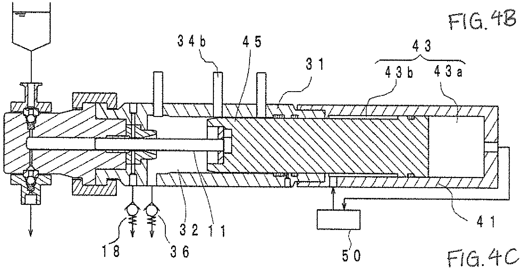
- the sensor 34c detects the piston shaft 45 when the piston 42 moves to a terminal end of the stroke so that the plunger 11 is drawn into the storage chamber 32.
- the proximity switch or the limit switch may be used as the sensor 34.
- the sensor with self-diagnosis function is used as the sensor 34b for detecting the bottom dead center.
- the sensor with self-diagnosis function is capable of detecting failure of the sensor so that the power supply to the apparatus is shut off. If the sensor 34b cannot detect the bottom dead center, it may be determined that the plunger is retracted to the retraction end. In the material pressurizing process, retraction of the plunger 11 to the retraction end allows the material to flow into the storage chamber 32. This may cause unexpected defects of the piston pump 10, for example, galling of the plunger 11, and damage to the third check valve 36, a thermometer 38, and a steam drain 37.
- the sensor 34b with self-diagnosis function makes it possible to prevent defects of the piston pump 10 and outflow of the material.
- the timer may issue warning, or shut off the power supply to the drive cylinder 46 when the time taken for the drive cylinder 46 that linearly drives the plunger 11 to retract from the top dead center to the bottom top center exceeds the predetermined time period.
- the piston pump 10 ensures detection of damage to the sensor 34b.
- a drain hole 35 is formed at the rear part of the storage member chamber 31.
- the packing 35a is disposed to the front of the drain hole 35.
- the drain hole 35 and the packing 35a serve to prevent the working fluid from leaking toward the storage chamber 32 or the steam/cleaning liquid from leaking toward the cylinder member 41 even if the sealing of the packing 35b is broken.
- the exhaust port 33 is disposed at the lower side of the storage chamber 32 in the gravity direction, and preferably, at the lower side in the gravity direction to the front (at the side of the compressing material cylinder 21) of the storage chamber 32.
- the exhaust port 33 discharges the cleaning liquid or the condensed water from steam, which has entered into the cylinder chamber 22.
- the piston pump 10 is disposed with inclination at the slight angle so that the cylinder head 21a is disposed at the lower side in the gravity direction. Therefore, the condensed water from steam or the cleaning liquid flowing into the storage chamber 32 may be appropriately discharged without being remained therein.
- the exhaust flow passage 30 is connected to the steam drain 37 and the third check valve 36.
- the third check valve 36 serves to prevent inflow of the fluid from the exhaust port 33 into the storage chamber 32.
- the steam drain 37 functions in discharging water generated by steam condensation upon decrease in the steam temperature as a result of heat exchange between the respective components of the piston pump 10 and the steam. As the steam drain 37 is disposed in the exhaust flow passage 30 from the exhaust port 33 at the lowermost part of the storage chamber 32, water generated in the storage chamber 32 is unlikely to be remained therein.
- the cleaning liquid and the like is remained in the storage chamber 32, there may cause such risks as deposition of the solute of the cleaning liquid on the wall surface of the storage chamber 32, adhesion of impurities revealed after washing with the cleaning liquid, or proliferation of unwanted bacteria in the remained cleaning liquid, deposited solute, adhered impurities, or inside of the steam drain.
- the exhaust port 33 is disposed at the lower side of the end of the storage chamber 32 closer to the cylinder chamber 22 in the gravity direction, the aforementioned risks may be prevented.
- thermocouple thermocouple, resistance temperature detector, and resistance thermometer 38 like thermistor between the exhaust port 33 and the steam drain 37 for confirming whether each temperature of the cylinder chamber 22 and the storage chamber 32 has reached the predetermined temperature upon steam sterilization.
- the sterilizing effect is ensured by keeping the predetermined temperature for a predetermined period of time.
- the plunger guide 12 is inserted into the through hole 31b formed in the partition 31a from the side of the material compressing cylinder 21 for storage.
- the through hole 31b is a stepped hole having a front part with expanded diameter.
- the plunger guide 12 has a stepped cylindrical shape, while having the outer surface inserted into the through hole 31b in the fitted state.
- the plunger guide 12 has a through hole 12a through which the plunger 11 passes.
- the through hole 12a is communicated with the packing storage part 22b of the cylinder chamber 22.
- the rear end of the through hole 12a has a substantially conical surface 12b with its section gradually expanded toward the storage chamber 32.
- the plunger 11 at the side of the cylinder chamber 22 lies while being inclined at the lower side in the gravity direction.
- penetrating the plunger 11 into the cylinder chamber 22 again from the position where it is drawn into the storage chamber 32 one end of the plunger 11 is guided by the substantially conical surface 12b so as to smoothly pass through the
- the substantially conical surface 12b may include the curved surface such as the conical surface, spindle surface, and bell-like surface so long as it has the function for guiding the plunger 11 toward the cylinder chamber 22.
- the plunger guide 12 includes a cooling piping 15.
- the cooling piping 15 is configured to pass through the storage chamber member 31 from its upper outer surface to be opened while communicating with the through hole 12a, further extend downward from the through hole 12a, and communicate with an exhaust port 20 of the coolant, which opens to the outer surface of the storage chamber member 31 at the lower side.
- a coolant generation device 81 generates the coolant as pure water, which is then supplied to the cooling piping 15.
- the coolant passes through the cooling piping 15 and the through hole 12a, and is supplied to the packing 23.
- the coolant serves to moisturize the packing 23, and to take heat generated by sliding motion of the plunger 11 against the packing 23 so as to be discharged from the exhaust port 20.
- the coolant further serves as the lubricant between the plunger 11 and the packing 23.
- a drain 19 and a check valve 18 are formed in the exhaust flow passage communicated with the exhaust port 20.
- the linear drive unit 40 will be described referring to Figs. 1 and 2 .
- the linear drive unit 40 includes the drive cylinder 46 and the hydraulic device 50 as the working fluid supply unit.
- the hydraulic device 50 may be disposed inside the holder 14.
- the drive cylinder 46 includes the hollow cylindrical cylinder member 41 having a hollow section 43 therein, a cylindrical piston 42 which reciprocates inside the hollow section 43, and the piston shaft 45 integrally formed with the piston 42.
- the cylinder member 41 has one side connected to a rear end of the storage chamber member 31 via a screw mechanism.
- the piston shaft 45 slidably moves along the inner wall surface of the storage chamber 32, and reciprocates inside the cylinder member 41 integrally with the piston 42.
- the piston 42 serves to partition the hollow section 43 into a first chamber 43a and a second chamber 43b each as the working fluid chamber.
- the space defined by the rear end of the piston 42 and the inner surface of the cylinder member 41 is the first chamber 43a, and the space defined by the front end surface of the piston 42, the piston shaft 45 and the inner surface of the cylinder member 41 is the second chamber 43b.
- the whole stroke of the drive cylinder 46 is derived from adding an extra stroke in which the plunger 11 is drawn into the storage chamber 32 from the bottom dead center to the distance from the top dead center to the bottom dead center of the plunger 11 (reciprocating stroke) in the material processing.
- piston 42 and the piston shaft 45 are integrally formed. It is also possible to assemble them as separate members.
- the cylinder member 41 includes working fluid inlet-outlet ports 44a and 44b for supplying and discharging the working fluid to and from the first chamber 43a and the second chamber 43b, respectively.
- the hydraulic oil is used as the working fluid
- the hydraulic cylinder is used as the drive cylinder 46.
- incompressible fluid for example, the hydraulic oil, high-pressure water and the like as the working fluid.
- the plunger 11 may be retracted toward the storage chamber 32 by switching a direction switching valve 54 of the hydraulic device 50 to supply the hydraulic oil to the second chamber 43b.
- the hydraulic device 50 is configured to supply and discharge the hydraulic oil to and from the first chamber 43a and the second chamber 43b of the drive cylinder 46, and to constitute a hydraulic open circuit including a tank 51 which stores the hydraulic oil, a hydraulic pump 52 which sucks the hydraulic oil from the tank 51 and discharge the sucked hydraulic oil to the hydraulic oil supply flow passage, a motor 53 for driving the hydraulic pump 52, a first flow passage communicated with the first chamber 43a, a second flow passage communicated with the second chamber 43b, the direction switching valve 54 for switching connection to the hydraulic oil supply flow passage, and a relief valve 55.
- the hydraulic device with closed circuit including a reversible motor and a bidirectional discharging hydraulic pump, and connecting two ports of the hydraulic pump to the hydraulic oil inlet-outlet ports 44a, 44b, respectively in place of the hydraulic device 50 with the direction switching valve 54.
- the variable capacity type hydraulic pump it is possible to employ the variable capacity type hydraulic pump to cancel the difference in the amount between the supply and discharge of the hydraulic oil to be determined depending on existence of the piston shaft 45 in the first chamber 43a and the second chamber 43b, and the hydraulic device with the hydraulic oil charging circuit and the like.
- various kinds of hydraulic devices are commercially available, they can be selected in accordance with actual size of the piston pump 10 according to the present invention and processing conditions.
- a servo mechanism including the linear drive guide, the ball screw, and the servo motor, and the linear drive mechanism, for example, linear motor and the like for constituting the linear drive unit 40 according to the present invention.
- a high pressure water generator may be employed instead of the hydraulic device 50.
- the material compressing cylinder 21 has a first check valve 71 disposed in a suction flow passage for communicating the intake port 61 and the cylinder chamber 22 at the upper side of the head 21a than the cylinder chamber 22.
- the first check valve 71 serves to supply the material, steam or cleaning liquid poured into the intake port 61 to the cylinder chamber 22, and to prevent the backflow of the material pressurized by the plunger 11 to the intake port 61.
- the first check valve 71 includes a spherical valve body 73, a valve seat 74 with a conical valve seat surface for receiving the valve body 73, a spring 76 and a housing 75.
- the valve seat 74 has substantially a columnar shape, having tapered surfaces 74a on both sides.
- the tapered surface 74a, the cylinder 21 and the housing 75 around the intake port 61 are assembled fluid-tightly in abutment on one another.
- the spring 76 urges the valve body 73 toward the valve seat 74.
- Each constituent of the check valve 71 has a simple shape suitable for cleaning and sterilization.
- the valve body 73, the housing 75, and the spring 76 are formed of anti-corrosion metal.
- the super engineering plastic such as PTFE, PEEK, PES, and PI may be employed for forming the valve seat 74.
- the wear resistant resin is employed for forming the valve seat 74.
- the valve seat 74 is made from the resin with hot water resistance, pressure resistance, and chemical resistance, thus it is sufficiently resistant against pressure applied by the material in compression, and steam temperature, additionally, allowing stationary cleaning with various types of liquid medicine.
- the resin valve seat 74 is capable of preventing generation of harmful abrasion powder owing to contact with the valve body 73, and mixture of the abrasion powder with the material.
- the resin valve seat 74 is elastically deformable when it is tightened into the housing 75 so as to ensure sealing between the housing 75 and the cylinder chamber 22.
- the cracking pressure of the first check valve 71 is set to be in the range from 0.003 to 0.02 MPa, and more preferably, from 0.003 to 0.01 MPa. As the cracking pressure is set to a significantly low value, the first check valve 71 is opened against urging force of the spring 76 by dead weight of the material in a material container 91, and the negative pressure generated in the cylinder chamber 22. Upon retraction of the plunger 11, the material flows from the material container 91 into the cylinder chamber 22, that is, the piston pump 10 sucks the material during retraction of the plunger.
- the piston pump 10 does not require the additional pump for pressurizing the material, thus preventing mixture of impurities and unwanted bacteria with the material.
- the intake port 61 is disposed coaxially with the first check valve 71.
- the member provided with the intake port 61 is fastened to the material compressing cylinder 21 with the bolt 16 so that the first check valve 71 is fixed coaxially between the cylinder 21 and the member of the intake port 61.
- the first check valve 71 and the member of the intake port 61 may be easily disassembled from the cylinder 21 needed for cleaning, sterilization or replacement, and also re-assembled.
- the outlet port 62 is disposed on the cylinder head 21a so as to be opened at the lower side in the gravity direction.
- the second check valve 72 is disposed at the lower side of the cylinder head 21a than the cylinder chamber 22 in the gravity direction in the discharge flow passage 64 for communicating the outlet port 62 and the cylinder chamber 22.
- the second check valve 72 is closed when the plunger 11 moves to suck the material, the cleaning liquid, or steam into the cylinder chamber 22, and opened when the plunger 11 moves to pressurize the material.
- the material pressurized in the cylinder chamber 22 as a result of advancement of the plunger 11 is discharged from the outlet port 62, and fed to a chamber 92.
- the second check valve 72 is similarly structured to the first check valve 71, and has the similar fixation structure to the intake port 61, which allows the member with the outlet port 62 to be disassembled from the material compressing cylinder 21. Accordingly, the detailed description will be omitted.
- thermometer 39 is disposed around the outlet port 62 so as to allow measurement of the temperature of steam discharged from the outlet port 62 upon sterilization.
- the piston pump When pressurizing the material, the piston pump will function as follows. Upon supply of the hydraulic oil to the first chamber 43a by the hydraulic device 50, it is discharged from the second chamber 43b into the tank 51 so that the plunger 11 moves forward. At this time, the material within the cylinder chamber 22 is compressed to raise the pressure. When the pressure exceeds the cracking pressure of the second check valve 72, the second check valve 72 is opened so that the pressurized material is discharged from the outlet port 62.
- the sensor 34a detects the piston shaft 45.
- the hydraulic device 50 switches the hydraulic oil supply to the second chamber 43b.
- the hydraulic oil in the first chamber 43a is discharged into the tank 51 so that the plunger 11 moves backward.
- the first check valve 71 is opened so that the material flows into the cylinder chamber 22 from the intake port 61.
- the hydraulic device 50 moves the piston 42 toward the rear end of the cylinder member 41.
- the sensor 34b detects the operation.
- the hydraulic device 50 then supplies the hydraulic oil to the second chamber 43b so that the piston 42 moves to the terminal end of the cylinder member 41 at the stroke end as shown in Fig. 4C .
- the sensor 34c detects the piston shaft 45.
- the cleaning liquid or steam is supplied from the intake port 61.
- the cleaning liquid or steam flows from the cylinder chamber 22 to the inside of the storage chamber 32 so that the liquid contact portion of the piston pump 10 is entirely cleaned or sterilized.
- Use of alkaline cleaning liquid is suitable for the organic base material, and use of neutral cleaning liquid is suitable for the pharmaceutical products.
- the concentration of the cleaning liquid is adjusted in accordance with the material.
- the flow rate ranging from 1 to 2 m/s is suitably set for the inside of the material cylinder chamber 22.
- the top end of the plunger 11 is required to pass through the packing 23.
- the space may be formed into the cylindrical shape, the spline groove, and the helical groove besides the conical shape.
- the plunger 11 may be stored completely in the storage chamber 32.
- the cleaning liquid which has passed through the first check valve 71 from the intake port 61 flows into the cylinder chamber 22 for passage in contact with the packing 23. It further flows into the storage chamber 32 so as to be discharged from the outlet port 33. As described above, the cleaning liquid flows into the storage chamber 32 from the cylinder chamber 22. If the storage chamber 32 is contaminated, such contaminant is dissolved in the cleaning liquid, and discharged without intruding into the cylinder chamber 22.
- the cleaning liquid flows in contact with the packing 23 which tends to be structurally contaminated to proliferate unwanted bacteria, and then is discharged from the storage chamber 32. Accordingly, backflow of the contaminant to the cylinder chamber 22 does not occur.
- the cleaning liquid flows only from the cylinder head 21a, and discharged from the storage chamber 32, which ensures to keep the inside of the cylinder chamber 22 as the important point for pressurizing the material in the clean state.
- Part of the cleaning liquid supplied from the intake port 61 is discharged from the outlet port 62 through the second check valve 72 without flowing into the cylinder chamber 22.
- the plunger 11 is retracted until it is drawn into the storage chamber 32 as described above. Then the steam at the temperature equal to or higher than 121°C (gauge pressure: equal to or higher than 0.12 MPa) is supplied from the intake port 61. The supplied steam flows into the cylinder chamber 22 and passes in contact with the packing 23 likewise the cleaning liquid, and further flows into the storage chamber 32. The condensed water from steam is discharged from the outlet port 62 or the exhaust port 33. If the device is filled with steam at the temperature equal to or higher than 121°C, the temperature detection unit provided for the exhaust port 33 measures the temperature of 121°C or higher. The sterilization is continued until the temperature detection unit provided for the exhaust port 33 continuously indicates 121°C or higher at least for 15 minutes or longer as specified by Japanese Pharmacopeia.
- 121°C gauge pressure: equal to or higher than 0.12 MPa
- the hydraulic device 50 supplies the hydraulic oil to the first chamber 43a upon transition of the process to the material processing step from cleaning or sterilization step.
- the sensor 34a detects the piston shaft 45.
- the hydraulic device 50 switches the hydraulic oil supply to the second chamber 43b. The plunger 11 starts retracting so that the material is supplied from the material container 91 for starting pressurization.
- the material processing apparatus 90 includes the material container 91, the piston pump 10, the chamber 92, a heat exchanger 93, a steam generator 94, and a cleaning liquid injection device 95.
- the material container 91 with a cup-like shape has a material exhaust port 91a formed in the bottom of the container.
- the material exhaust port 91a and the intake port 61 are communicated with a piping 96.
- the piping 96 is provided with a branch port 96a which is constantly sealed with the plug. Upon stationary cleaning, the cleaning liquid injection device 95 is connected to the branch port 96a.
- the steam generator 94 Upon stationary sterilization, the steam generator 94 is connected to the branch port 96a.
- the outlet port 62 is communicated with an inlet 92a of the chamber 92.
- the material pressurized into high pressure by the piston pump 10 in the material processing step will impinge against the ball (not shown) in the form of jet in the chamber 92. Impingement of the material jet against the ball may atomize particles contained in the material, or emulsify the material.
- the known chamber as disclosed in Japanese Patent Nos. 3151706 and 3686528 may be applied to the chamber 92.
- the processed material discharged from a chamber outlet 92b is cooled by the heat exchanger 93, and then returned to the material container 91.
- a double tube type counterflow heat exchanger may be employed as the heat exchanger 93.
- Use of the double tube type counterflow heat exchanger allows reduction in the area of the wall surface of the heat exchanger in contact with the processed material. As the material contact surface on the inner surface of the heat exchanger is smooth and simply shaped, it is likely to keep the heat exchanger clean. Additionally, the steam allows easy sterilization.
- the above-structured material processing apparatus 90 makes it possible to process the material continuously with repetition appropriately.
- branch port 96a It is possible to replace the branch port 96a with a three-way valve. It is also possible to provide the needle valve through which the branch port 96a is connected to the steam generator 94 or the cleaning liquid injection device 95 instead of sealing the branch port with the plug.
- the material processing apparatus using the piston pump 10 may be configured to use two piston pumps which alternately performs compression for atomization or emulsification of the material.
- the material is pressurized by the respective piston pumps into high pressure ranging from 100 MPa to 245 MPa so that the material is injected alternately in the chamber 92.
- the material injected in the chamber 92 is sent to the heat exchanger 93 so as to be cooled. If the material is processed into the desired state (particle size, viscosity), it will be collected later. If the material has not yet reached into the desired state, it is sent to the piston pump 10 again.
- the aforementioned structure ensures more efficient material processing.
- the piston pump according to the embodiment is suitable for pressurizing the material into the pressure ranging from 100 MPa to 245 MPa in the atomization apparatus or the emulsification apparatus of high pressure injection type.
- the aforementioned piston pump is suitable for the use in such field as food, pharmaceutical products, and cosmetics requiring sterilization of the manufacturing system with high frequency.
- titanium oxide employed for the foundation and the sunscreen is subjected to 10-pass at 245 MPa, it will be atomized to reduce the median diameter from 2 ⁇ m to 0.065 ⁇ m.
- Use of the product containing the general particle size may make the skin spread with such product look too white, that is, the unnatural look.
- use of the product containing atomized particles allows the skin to maintain its transparency.
- magnesium hydroxide employed for the laxative (purgative) and an antacid (gastric acid neutralization) is subjected to 10-pass at 245 PMa, it will be atomized to reduce the median diameter from 4.5 ⁇ m to 0.25 ⁇ m. The atomization increases the specific surface area of the particle, thus providing the similar medical effects to the one derived from generally employed art even while reducing the usage of the material.
Landscapes
- Engineering & Computer Science (AREA)
- Mechanical Engineering (AREA)
- General Engineering & Computer Science (AREA)
- Reciprocating Pumps (AREA)
- Details Of Reciprocating Pumps (AREA)
Abstract

Description
- The present invention relates to a piston pump configured to pressurize the material, and feed the pressurized material, and more particularly, to the piston pump which can be stationary sterilized and stationary cleaned.
- Recently, there has been an apparatus which pressurizes the material so as to be injected for atomization or emulsification in production of pharmaceutical products and cosmetics. There may often be the case that the piston pump used for material pressurization is needed to be cleaned and sterilized.
Japanese Unexamined Patent Application Publication No. 2011-12591 - As the aforementioned pump is configured that the cleaning fluid is fed from the lower side upward, and then discharged, the material within the syringe (cylinder) is likely to be remained. The material in the cylinder often flows into the vacant chamber to cause jamming, resulting in damage to the apparatus.
- It is an object of the present invention to provide a piston pump for preventing contamination of the material and intrusion of the material into the storage chamber by avoiding the residual material in the cylinder for performing easy cleaning and sterilization.
- The present invention provides a piston pump provided with: a material compressing cylinder with a cylinder chamber having an open rear end; a plunger penetrated from the rear end into the cylinder chamber fluid-tightly, which reciprocates between a top dead center and a bottom dead center for feeding the material; a holder for supporting and fixing the material compressing cylinder with virtually horizontal inclination at a slight inclination angle with respect to a center axis along a reciprocating direction of the plunger so that a head of the cylinder is disposed at a lower side in a gravity direction; a hollow cylindrical storage chamber member which is coaxially connected to the rear end of the material compressing cylinder consecutively with a cylindrical space having a larger diameter than that of the cylinder chamber, including a storage chamber for receiving the plunger, and an exhaust port for discharging the fluid in the storage chamber; a linear drive unit having a reciprocating member which linearly reciprocates at a stroke longer than a distance between the top dead center and the bottom dead center of the plunger parallel thereto, and allowing the plunger to reciprocate via the reciprocating member; an intake port disposed on the head of the material compressing cylinder upward in the gravity direction, which is switchably communicated with a material supply source, a cleaning liquid supply source, and a steam supply source; an intake flow passage for communicating the intake port with the cylinder chamber; an outlet port disposed on the head of the material compressing cylinder downward in the gravity direction; an outlet flow passage for communicating the outlet port with the cylinder chamber; a first check valve disposed in the intake flow passage; and a second check valve disposed in the outlet flow passage. The storage chamber member is configured that the plunger is drawn into the storage chamber, and the cylinder chamber and the storage chamber are communicated when the reciprocating member of the linear drive unit moves to a terminal end of the stroke.
- Effects derived from the piston pump according to the present invention will be described as below.
- (1) The material compressing cylinder is fixed to a holder while having its head slightly inclined so as to be at the lower side in the gravity direction. This structure is capable of preventing the liquid from being remained in the cylinder chamber after cleaning or sterilization.
- (2) The intake port is disposed on the cylinder head, which is directed upward. The material may be fed into the cylinder chamber by gravity and the negative pressure inside the cylinder chamber resulting from retraction of the plunger.
- (3) As the material compressing cylinder is inclined so that the outlet port disposed on the cylinder head at the lower side in the gravity direction is directed downward in the gravity direction, the material fed into the cylinder chamber is appropriately discharged from the outlet port without being remained in the cylinder chamber as the plunger advances.
- (4) A hollow cylindrical storage chamber member, which includes the storage chamber as a large-diameter cylindrical space compared with the cylinder chamber is communicated with the rear end of the material compressing cylinder so that the linear drive unit draws the plunger into the storage chamber. This makes it possible to clean or sterilize the plunger inside the storage chamber by pouring the cleaning fluid or steam from the intake port into the cylinder chamber.
- (5) When the plunger is drawn into the storage chamber during cleaning or sterilization, the cylinder chamber is communicated with the storage chamber so that the communicated area is also cleaned and sterilized. This makes it possible to clean and sterilize the sealing member which ensures fluid-tight penetration of the plunger through the cylinder chamber, for example, the packing disposed in the cylinder chamber open end region.
- (6) The exhaust port is disposed in the storage chamber member so that the fluid inside the storage chamber is discharged. Either the cleaning fluid or steam is fed from the intake port of the cylinder head into the cylinder chamber, and brought into contact with the inner surface of the cylinder chamber. It is then fed into the storage chamber so as to be discharged outside the storage chamber via the exhaust port. There is no risk which has occurred in the generally employed structure in which the cleaning fluid flows from the storage chamber side to the head of the cylinder chamber. In other words, there is no risk that impurities on the storage chamber are dissolved in the cleaning liquid and re-adhered onto the inside of the cylinder chamber.
- Preferably, the piston pump according to the present invention has its inclination angle equal to or larger than 0.5°, and smaller than 5°. The aforementioned structure prevents residual liquid inside the cylinder chamber, and allows appropriate intake and discharge of the material so as to discharge the cleaning liquid and steam after cleaning and sterilization.
- Preferably, the linear drive unit of the piston pump is provided with a drive cylinder which includes a cylinder member coaxially connected to a rear part of the storage chamber member consecutively, a piston as the reciprocating member for reciprocating in the cylinder member, which is slidably disposed in the cylinder member for partitioning an inner space of the cylinder member into a first chamber and a second chamber, and a piston shaft having a rear end fixed to the piston, and a top end holding the plunger so as to be linearly driven from the inside of the cylinder member to the inside of the storage chamber, and a working fluid supply unit which controls to switch supply and discharge of the working fluid between the first chamber and the second chamber for controlling drive of the reciprocating motion of the piston.
- The piston pump may be constituted by the simple structure as described above. The drive cylinder is configured that the piston reciprocates in the cylinder member so as to reciprocate the plunger at the side of the material compressing cylinder via the piston shaft at the top end of the piston. In the case where the material compressing cylinder is disposed downward in the gravity direction, having the sealing member between the piston shaft and the storage chamber member broken, the working fluid will intrude into the storage chamber in the gravity direction from the part between the piston shaft and the cylinder. The working fluid further intrudes into the cylinder chamber of the material compressing cylinder positioned in the gravity direction. On the contrary, the piston pump according to the present invention prevents the working fluid from intruding into the material compressing cylinder even if the working fluid intrudes into the storage chamber through the broken sealing member because the material compressing cylinder is disposed with virtually horizontal inclination. Accordingly, the material compressing cylinder is unlikely to be contaminated with the working fluid.
- Preferably, the piston pump according to the present invention includes a connection member for detachably connecting the rear end of the material compressing cylinder and a front end of the storage chamber member. The aforementioned structure allows the material compressing cylinder and the storage chamber member to be disassembled, and re-assembled again. Besides the cleaning on an as-necessary basis in using the piston pump, the separated material compressing cylinder and the storage chamber member may be cleaned with great care, respectively after execution of the single material processing step. In this case, the sealing member such as the packing disposed between the members may be readily detached so as to be easily cleaned and replaced. Preferably, the connection member is simply configured to solidly connect the material compressing cylinder and the storage chamber member coaxially, and to be easily disassembled and re-assembled.
- Preferably, the connection member includes a first flange portion which protrudes on an outer circumference at a location to the front of an insertion portion cylindrically extending from a rear side of the material compressing cylinder, a second flange portion which protrudes on an outer circumference of an opening edge of a recess receiving portion which is formed at a front end of the storage chamber member for receiving the insertion portion into a fitted state, and includes a front surface in contact with a rear surface of the first flange portion in the fitted state of the insertion portion, and a clamp unit which clamps to connect the first flange portion and the second flange portion for connecting the material compressing cylinder and the storage chamber member.
- The cylindrical insertion portion of the material compressing cylinder is inserted into a recess receiving portion of the storage chamber member while being fitted therewith. It is therefore possible to easily assemble the material compressing cylinder and the storage chamber member so that the cylinder chamber, the plunger and the storage chamber become coaxial. The first flange portion and the second flange portion abut on each other while having rear side surface and the front side surface brought into contact state. By clamping the first and the second flange portions with the clamp unit, the material compressing cylinder and the chamber members may be connected coaxially and fixedly with ease. The connection may be easily released from the fixed state by disengaging the clamp unit.
- Preferably, the exhaust port of the piston pump is disposed at the lower side of the storage chamber member in the gravity direction at its end closer to the material compressing cylinder.
- The exhaust port is disposed at the lowermost position of the inner part of the storage chamber in the gravity direction. Therefore, the cleaning fluid is hardly remained in the storage chamber after cleaning. This makes it possible to keep the piston pump clean.
- Preferably, the piston pump according to the present invention further includes a third check valve disposed in an exhaust flow passage communicated with the exhaust port for preventing a backflow of the fluid to the inside of the storage chamber.
- Even if the inner pressure of the storage chamber becomes negative in the state where the exhaust port is not closed, the third check valve is always capable of preventing the backflow of the waste liquid.
- Preferably, the piston pump according to the present invention includes a plunger guide between the open end of the cylinder chamber of the material compressing cylinder and the storage chamber, having an inner diameter expanded toward the storage chamber, and a through whole which allows the plunger to pass therethrough.
- This structure ensures to penetrate the plunger which has been drawn into the storage chamber after cleaning from the open end of the cylinder chamber inward along the plunger guide.
- Preferably, the piston pump according to the present invention further includes a branch port disposed in a middle of a piping communicated with the intake port from outside, and a steam drain communicated with the discharge flow passage from the exhaust port.
- The intake port may be communicated with the material supply source, the cleaning liquid supply source, and the steam supply source via the branch port. Upon cleaning, the cleaning fluid supplied from the branch port into the piping is poured into the intake port, and flows into the cylinder chamber through the first check valve. It further flows into the storage chamber, and then discharged from the exhaust port through the exhaust flow passage. Upon sterilization, the steam supplied from the branch port into the piping, and poured into the intake port is subjected to heat exchange with the piston pump, and condensed. The water generated through condensation of the steam is then discharged from the steam drain. As the non-coagulated steam cannot be discharged from the steam drain, the cylinder chamber and the storage chamber are filled with the steam, thus effectively sterilizing the inside of the piston pump.
- Preferably, the first check valve of the piston pump according to the present invention includes a spherical valve body, a valve seat made from super engineering plastic, and a spring which urges the valve body on the valve seat for sealing the material, and sets a cracking pressure of the check valve to a value ranging from 0.003 to 0.02 MPa.
- The aforementioned structure needs no additional pump for pressurizing the material to be poured. It is difficult to clean and sterilize such pump with wide liquid-contact area. As the present invention requires no such pump for pressurizing and pouring the material, impurities and unwanted bacteria are unlikely to be mixed with the material.
- Preferably, a material processing apparatus according to the present invention include the piston pump, a material container for storing the material, and an intake piping for communicating the material container and the intake port.
- The material is sucked from the material container into the cylinder chamber as the plunger retracts, and discharged from the outlet port as the plunger advances. The reciprocating motion of the plunger allows appropriate consecutive processing of atomization or emulsification of the material.
- The piston pump according to the present invention prevents the material from being remained in the cylinder, resulting in advantageous effects of preventing contamination of the material, and easy cleaning or sterilization of the storage chamber.
-
-
Fig. 1 is a longitudinal sectional view of a piston pump according to an embodiment of the present invention; -
Fig. 2 is a view showing a piping of the piston pump according to the embodiment of the present invention; -
Fig. 3 is a longitudinal enlarged sectional view of a cylinder head of the piston pump as shown inFig. 1 ; -
Figs. 4A to 4C represent each operation of the piston pump as shown inFig. 1 in the respective steps, wherein:-
Fig. 4A shows the state where a plunger has reached a top dead center; -
Fig. 4B shows the state where the plunger has reached a bottom dead center; and -
Fig. 4C shows the state where the plunger has moved to a terminal end of the stroke.
-
- Referring to
Figs. 1 and2 , a piston pump according to an embodiment of the present invention includes: a material compressing cylinder 21 which contains a cylindrical cylinder chamber 22 having an open rear end therein; a plunger 11 having a rear end penetrated into the cylinder chamber 22 for reciprocation between the top dead center and the bottom dead center for feeding the material; a packing 23 applied to the inner wall surface of the cylinder chamber 22 at the open end side for sealing the space between the cylinder chamber and the plunger 11; a holder 14 for supporting and fixing the material compressing cylinder 21 with its center axis X virtually horizontal inclination at the slight inclination angle with respect to the horizontal axis H so that a columnar shaped head 21a of the cylinder 21 is positioned at the lower side in the gravity direction; a hollow cylindrical storage chamber member 31 which is coaxially connected to the rear part of the material compressing cylinder 21 consecutively, including a storage chamber 32 for receiving the other end of the plunger 11 reciprocating outside the cylinder chamber 22, and an exhaust port 33 for discharging the cleaning liquid or steam inside the storage chamber 32; a drive cylinder 46 for directly driving the plunger 11 for reciprocation, a hydraulic device 50 for operating the drive cylinder 46 by controlling operations of feeding and discharging the working fluid, both of which constitute the linear drive unit 40; an intake port 61 directed upward in the gravity direction for supplying the material, steam or cleaning fluid into the cylinder chamber 22; an outlet port 62 directed downward in the gravity direction for discharging the material pressurized by the plunger 11 in the cylinder chamber 22; a first check valve 71 provided for an intake flow passage 63 for communicating the intake port 61 with the cylinder chamber 22; a second check valve 72 provided for a discharge flow passage 64 for communicating the outlet port 62 with the cylinder chamber 22, and a third check valve 36 provided for an exhaust flow passage 30 communicated with the exhaust port 33 for preventing the backflow of the fluid into the storage chamber 32. - In the embodiment, the direction toward the head 21a from the center of the
material compressing cylinder 21 will be referred to as front, and the direction toward thestorage chamber member 31 from the center will be referred to as rear. - Preferably, the inclination angle α of the holder 14 for support and fixation of the
material compressing cylinder 21 in the inclined state is equal to or larger than 0.5° and smaller than 5°, and more preferably, equal to or larger than 1/100° (0.573°) and smaller than 1°. The 1/100 gradient is specified in Guideline for production of sterilized pharmaceutical products (published by Ministry of Health, Labour and Welfare) . The gradient is specified so that the liquid within thecylinder chamber 22 flows down by gravity. As thematerial compressing cylinder 21 is disposed at the slight inclination angle with virtually horizontal inclination so that the head 21a is located at the lower side in the gravity direction, the material is not remained in thecylinder chamber 22. If the inclination angle α exceeds 5°, operability of disassembling of thepiston pump 10 for cleaning, and re-assembling thereafter will be deteriorated. Theintake port 61 is easily disposed on the upper surface of thematerial compressing cylinder 21 perpendicularly to the cylinder center axis X. However, if the gradient of theintake port 61 is 5° or larger, the material cannot be smoothly supplied by gravity. In the inclined state at the angle of 1°, the material may be smoothly supplied only by gravity and the negative pressure caused by retraction of the plunger 11. - As the
material compressing cylinder 21 is disposed on the holder 14 with virtually horizontal inclination, the working fluid never intrudes into thecylinder chamber 22 of thematerial compressing cylinder 21 even if sealing of a packing 35b formed between thestorage chamber member 31 and thepiston shaft 45 of thedrive cylinder 46 is broken. This makes it possible to keep inside of thecylinder chamber 22 clean. - As the material pressure in the
cylinder chamber 22 is expected to reach the high value ranging from 100 MPa to 245 MPa, thematerial compressing cylinder 21 is configured to have the thickness sufficient to resist the high pressure as described above. The anti-corrosion metal such as precipitation hardening type stainless steel and austenitic stainless steel is used for manufacturing thecylinder 21 so as to withstand washing with liquid medicine. - The cleaning liquid may be a basic detergent mainly composed of a surfactant and an inorganic base such as aqueous solution of inorganic base, aqueous solution of inorganic acid, sodium hydroxide, and potassium hydroxide, acidic detergent mainly composed of a surfactant and an inorganic acid, basic disinfectant mainly composed of sodium hypochlorite, active chlorine, and surfactant, a non-polar solvent, and other liquid medicine.
- The
cylinder chamber 22 of thematerial compressing cylinder 21 includes a recess packing storage part 22b formed in the inner wall surface in the region at the open end side. The packing 23 as the member for sealing the space between the cylinder chamber and the plunger 11 extends from the inside of the packing storage part 22b toward thestorage chamber member 31. The packing 23 is provided with at least one, preferably, a plurality of seal members in tight contact state. The packing 23 constituted by the plurality of seal members is shaped adaptable to sealing performance. The packing 23 may be configured to include a support member for positionaly supporting the plunger 11 at the axial center of thecylinder 21. - Arbitrary material may be used for forming the packing 23 so long as pressure resistance against the pressure for pressurizing the material, heat resistance against temperature of the steam poured into the cylinder chamber for sterilization, and chemical/corrosion resistance against the liquid medicine in the form of steam or the cleaning liquid are simultaneously ensured. It is possible to employ the material such as polytetrafluoroethylene (PTFE), polyetherethelketone (PEEK), polyethersulfone (PFE), polyimide (PI), other super engineering plastics, copolymer containing any of those plastics, and CFRP for producing the packing 23.
- The packing 23 disposed in the tight contact state is protected from being fixed by adhesion of the material to the part between the inner surface of the packing storage part 22b and the packing 23. As described above, the
material compressing cylinder 21 and thestorage chamber member 31 can be easily disassembled by removing theclamp unit 13 as the connection member. In the disassembled state, the packing 23 may also be disassembled for removal from the packing storage part 22b in thecylinder chamber 22. The packing 23 may be easily assembled with the packing storage part 22b upon re-assembly of thematerial compressing cylinder 21 and thestorage chamber member 31. - The plunger 11 as a columnar bar member may be formed of super steel, fine ceramics, and other high rigidity material. It is possible to subject the plunger 11 to the surface treatment process for wear resistance, for example, DLC (diamond-like carbon) coating, TiCN (titanium carbonitride) coating and the like in accordance with the material and the usage state.
- The plunger 11 has its rear end held with the
piston shaft 45 integrally formed with the piston 42 which slidably reciprocates within thedrive cylinder 46 by means of a fixture member 17 while ensuring a certain degree of freedom with respect to inclination and position. The plunger 11 has its end reciprocating within thecylinder chamber 22 as the piston 42 and thepiston shaft 45 are linearly driven. The plunger 11 which is held with the degree of freedom is allowed to reciprocate within thecylinder chamber 22 while having its posture maintained by the packing 23. - The plunger 11 reciprocates between the top dead center and the bottom dead center within the
cylinder chamber 22 upon pressurization of the material. Upon cleaning or sterilization, the plunger 11 retracts in thecylinder chamber 22 to be drawn into thestorage chamber 32 communicated with the rear part of thecylinder chamber 22 inside thestorage chamber member 31 communicated with the rear part of thematerial compressing cylinder 21. - The
storage chamber member 31 as the hollow cylindrical member forms thestorage chamber 32 as the inner cylindrical space. Thestorage chamber member 31 is coaxially connected to the rear part of thematerial compressing cylinder 21. A cylinder member 41 of thedrive cylinder 46 is coaxially connected to the rear end of thestorage chamber member 31 consecutively. Thematerial compressing cylinder 21, thestorage chamber member 31, and the cylinder member 41 of thedrive cylinder 46 integrally constitute a housing of thecylinder pump 10. The consecutive connection of the cylinder member 41 to thestorage chamber member 31 is realized by fastening screws, for example. - The front section of the
storage chamber member 31 is divided by a partition 31a at the side of thematerial compressing cylinder 21 so as to define thestorage chamber 32 by the inner surface of the partition 31a and thepiston shaft 45. Therefore thestorage chamber 32 is formed between the rear end side of thecylinder chamber 22 of thematerial compressing cylinder 21 and the piston 42 as the space which is larger than thecylinder chamber 22 in the radial direction, and has the length sufficient to allow the plunger 11 to be axially drawn from thecylinder chamber 22 to the rear of the packing 23. A substantially cylindrical through hole 31b formed in the center of the partition 31a allows aplunger guide 12 to be stored therein. - The
piston pump 10 includes the connection member for detachably connecting thematerial compressing cylinder 21 and thestorage chamber member 31. The connection member is constituted by a cylindrical insertion portion 21c extending from the rear side of thematerial compressing cylinder 21, afirst flange portion 21b protruding on the outer circumference at a location to the front of the insertion portion 21c, arecess receiving portion 31c formed to the front of the partition 31a of thestorage chamber member 31 for receiving the insertion portion 21c to be fit therewith, a second flange portion 31d having a front surface in contact with the rear surface of thefirst flange portion 21 in the fitted state with the insertion portion 21c while protruding on an open edge circumference of the receivingportion 31c, and aclamp unit 13 for clamping thefirst flange portion 21b and the second flange portion 31d which abut on each other. In the state where the insertion portion 21c is inserted into therecess receiving portion 31c to be fitted, thecylinder chamber 22 and thestorage chamber 32 are coaxially connected consecutively. In the aforementioned fitted state, the first and thesecond flange portions 21b, 31d which abut on each other are clamped with theclamp unit 13 so that coaxial connection between thematerial compressing cylinder 21 and thestorage chamber member 31 is fixed. The aforementioned connection may be released by simply removing theclamp unit 13. - The
clamp unit 13 is constituted by an annular member having a groove 13a therein, for example. Theclamp unit 13 has two divisions each having a semicircular shape. The respective ends of the two divisions of theclamp unit 13 are connected with connecting members, for example, bolt, nut, pin and the like. Thefirst flange portion 21b and the second flange portion 31d are clamped and fixed by the groove 13a of theclamp unit 13. At this time, thefirst flange portion 21b is urged on the second flange portion 31b. Theclamp unit 13 fixes thematerial compressing cylinder 21 to thestorage chamber member 31 against the pressure of the material compressed by the plunger 11 in thecylinder chamber 22. Theclamp unit 13 having two divisions fastened by the connecting member is easily detachable. Theclamp unit 13 is simply shaped so as to be easily cleaned for keeping the apparatus clean. - The
storage chamber member 31 is provided with sensors 34 (34a, 34b, 34c) for detecting thepiston shaft 45 of the piston 42. The sensor 34a detects the position of thepiston shaft 45 when the plunger 11 reaches the top dead center. Thesensor 34b detects the position of thepiston shaft 45 when the plunger 11 reaches the bottom dead center. The sensor 34c detects thepiston shaft 45 when the piston 42 moves to a terminal end of the stroke so that the plunger 11 is drawn into thestorage chamber 32. The proximity switch or the limit switch may be used as thesensor 34. Preferably, the sensor with self-diagnosis function is used as thesensor 34b for detecting the bottom dead center. Use of the sensor with self-diagnosis function is capable of detecting failure of the sensor so that the power supply to the apparatus is shut off. If thesensor 34b cannot detect the bottom dead center, it may be determined that the plunger is retracted to the retraction end. In the material pressurizing process, retraction of the plunger 11 to the retraction end allows the material to flow into thestorage chamber 32. This may cause unexpected defects of thepiston pump 10, for example, galling of the plunger 11, and damage to thethird check valve 36, a thermometer 38, and asteam drain 37. Thesensor 34b with self-diagnosis function makes it possible to prevent defects of thepiston pump 10 and outflow of the material. - It is possible to employ the generally available sensor and the timer for measuring the reciprocating time of the plunger 11 serving as the
sensor 34b in place of the b-contact sensor with self-diagnosis function. The use of the timer may issue warning, or shut off the power supply to thedrive cylinder 46 when the time taken for thedrive cylinder 46 that linearly drives the plunger 11 to retract from the top dead center to the bottom top center exceeds the predetermined time period. In this case, thepiston pump 10 ensures detection of damage to thesensor 34b. - A
drain hole 35 is formed at the rear part of thestorage member chamber 31. The packing 35a is disposed to the front of thedrain hole 35. Thedrain hole 35 and the packing 35a serve to prevent the working fluid from leaking toward thestorage chamber 32 or the steam/cleaning liquid from leaking toward the cylinder member 41 even if the sealing of the packing 35b is broken. - The exhaust port 33 is disposed at the lower side of the
storage chamber 32 in the gravity direction, and preferably, at the lower side in the gravity direction to the front (at the side of the compressing material cylinder 21) of thestorage chamber 32. The exhaust port 33 discharges the cleaning liquid or the condensed water from steam, which has entered into thecylinder chamber 22. Thepiston pump 10 is disposed with inclination at the slight angle so that the cylinder head 21a is disposed at the lower side in the gravity direction. Therefore, the condensed water from steam or the cleaning liquid flowing into thestorage chamber 32 may be appropriately discharged without being remained therein. - The exhaust flow passage 30 is connected to the
steam drain 37 and thethird check valve 36. Thethird check valve 36 serves to prevent inflow of the fluid from the exhaust port 33 into thestorage chamber 32. The steam drain 37 functions in discharging water generated by steam condensation upon decrease in the steam temperature as a result of heat exchange between the respective components of thepiston pump 10 and the steam. As thesteam drain 37 is disposed in the exhaust flow passage 30 from the exhaust port 33 at the lowermost part of thestorage chamber 32, water generated in thestorage chamber 32 is unlikely to be remained therein. If the cleaning liquid and the like is remained in thestorage chamber 32, there may cause such risks as deposition of the solute of the cleaning liquid on the wall surface of thestorage chamber 32, adhesion of impurities revealed after washing with the cleaning liquid, or proliferation of unwanted bacteria in the remained cleaning liquid, deposited solute, adhered impurities, or inside of the steam drain. As the exhaust port 33 is disposed at the lower side of the end of thestorage chamber 32 closer to thecylinder chamber 22 in the gravity direction, the aforementioned risks may be prevented. - It is preferable to dispose the temperature measurement device such as thermocouple, resistance temperature detector, and resistance thermometer 38 like thermistor between the exhaust port 33 and the
steam drain 37 for confirming whether each temperature of thecylinder chamber 22 and thestorage chamber 32 has reached the predetermined temperature upon steam sterilization. The sterilizing effect is ensured by keeping the predetermined temperature for a predetermined period of time. - The
plunger guide 12 is inserted into the through hole 31b formed in the partition 31a from the side of thematerial compressing cylinder 21 for storage. The through hole 31b is a stepped hole having a front part with expanded diameter. Theplunger guide 12 has a stepped cylindrical shape, while having the outer surface inserted into the through hole 31b in the fitted state. Theplunger guide 12 has a through hole 12a through which the plunger 11 passes. The through hole 12a is communicated with the packing storage part 22b of thecylinder chamber 22. The rear end of the through hole 12a has a substantially conical surface 12b with its section gradually expanded toward thestorage chamber 32. When the plunger 11 is drawn into thestorage chamber 32, the plunger 11 at the side of thecylinder chamber 22 lies while being inclined at the lower side in the gravity direction. When penetrating the plunger 11 into thecylinder chamber 22 again from the position where it is drawn into thestorage chamber 32, one end of the plunger 11 is guided by the substantially conical surface 12b so as to smoothly pass through the - through hole 12a. It further passes through the inside of the packing 23 so as to be appropriately inserted into the
cylinder chamber 22. The substantially conical surface 12b may include the curved surface such as the conical surface, spindle surface, and bell-like surface so long as it has the function for guiding the plunger 11 toward thecylinder chamber 22. - The
plunger guide 12 includes a coolingpiping 15. The coolingpiping 15 is configured to pass through thestorage chamber member 31 from its upper outer surface to be opened while communicating with the through hole 12a, further extend downward from the through hole 12a, and communicate with an exhaust port 20 of the coolant, which opens to the outer surface of thestorage chamber member 31 at the lower side. Acoolant generation device 81 generates the coolant as pure water, which is then supplied to the coolingpiping 15. The coolant passes through the coolingpiping 15 and the through hole 12a, and is supplied to the packing 23. The coolant serves to moisturize the packing 23, and to take heat generated by sliding motion of the plunger 11 against the packing 23 so as to be discharged from the exhaust port 20. The coolant further serves as the lubricant between the plunger 11 and the packing 23. Adrain 19 and acheck valve 18 are formed in the exhaust flow passage communicated with the exhaust port 20. Upon material processing, if the packing 23 causes leakage owing to abrasion, the leaked material is discharged to the exhaust port 20 so as to prevent intrusion of the material into thestorage chamber 32. The exhaust port 20 discharges the cleaning liquid or the condensed water from steam upon cleaning or sterilization. - The linear drive unit 40 will be described referring to
Figs. 1 and2 . The linear drive unit 40 includes thedrive cylinder 46 and thehydraulic device 50 as the working fluid supply unit. Thehydraulic device 50 may be disposed inside the holder 14. - Referring to
Fig. 1 , thedrive cylinder 46 will be described. Thedrive cylinder 46 includes the hollow cylindrical cylinder member 41 having ahollow section 43 therein, a cylindrical piston 42 which reciprocates inside thehollow section 43, and thepiston shaft 45 integrally formed with the piston 42. The cylinder member 41 has one side connected to a rear end of thestorage chamber member 31 via a screw mechanism. Thepiston shaft 45 slidably moves along the inner wall surface of thestorage chamber 32, and reciprocates inside the cylinder member 41 integrally with the piston 42. The piston 42 serves to partition thehollow section 43 into a first chamber 43a and asecond chamber 43b each as the working fluid chamber. The space defined by the rear end of the piston 42 and the inner surface of the cylinder member 41 is the first chamber 43a, and the space defined by the front end surface of the piston 42, thepiston shaft 45 and the inner surface of the cylinder member 41 is thesecond chamber 43b. - The whole stroke of the
drive cylinder 46 is derived from adding an extra stroke in which the plunger 11 is drawn into thestorage chamber 32 from the bottom dead center to the distance from the top dead center to the bottom dead center of the plunger 11 (reciprocating stroke) in the material processing. - In the embodiment, the piston 42 and the
piston shaft 45 are integrally formed. It is also possible to assemble them as separate members. - The cylinder member 41 includes working fluid inlet-outlet ports 44a and 44b for supplying and discharging the working fluid to and from the first chamber 43a and the
second chamber 43b, respectively. In this embodiment, the hydraulic oil is used as the working fluid, and the hydraulic cylinder is used as thedrive cylinder 46. However, in the present invention, it is possible to use incompressible fluid, for example, the hydraulic oil, high-pressure water and the like as the working fluid. The plunger 11 may be retracted toward thestorage chamber 32 by switching a direction switching valve 54 of thehydraulic device 50 to supply the hydraulic oil to thesecond chamber 43b. - The
hydraulic device 50 is configured to supply and discharge the hydraulic oil to and from the first chamber 43a and thesecond chamber 43b of thedrive cylinder 46, and to constitute a hydraulic open circuit including a tank 51 which stores the hydraulic oil, a hydraulic pump 52 which sucks the hydraulic oil from the tank 51 and discharge the sucked hydraulic oil to the hydraulic oil supply flow passage, a motor 53 for driving the hydraulic pump 52, a first flow passage communicated with the first chamber 43a, a second flow passage communicated with thesecond chamber 43b, the direction switching valve 54 for switching connection to the hydraulic oil supply flow passage, and a relief valve 55. - It is possible to constitute the efficient system with high response by using the hydraulic device with closed circuit including a reversible motor and a bidirectional discharging hydraulic pump, and connecting two ports of the hydraulic pump to the hydraulic oil inlet-outlet ports 44a, 44b, respectively in place of the
hydraulic device 50 with the direction switching valve 54. In the aforementioned case, it is possible to employ the variable capacity type hydraulic pump to cancel the difference in the amount between the supply and discharge of the hydraulic oil to be determined depending on existence of thepiston shaft 45 in the first chamber 43a and thesecond chamber 43b, and the hydraulic device with the hydraulic oil charging circuit and the like. As various kinds of hydraulic devices are commercially available, they can be selected in accordance with actual size of thepiston pump 10 according to the present invention and processing conditions. - It is possible to employ a servo mechanism including the linear drive guide, the ball screw, and the servo motor, and the linear drive mechanism, for example, linear motor and the like for constituting the linear drive unit 40 according to the present invention. In the case where the high pressure water is used as the working fluid, a high pressure water generator may be employed instead of the
hydraulic device 50. - The
material compressing cylinder 21 has afirst check valve 71 disposed in a suction flow passage for communicating theintake port 61 and thecylinder chamber 22 at the upper side of the head 21a than thecylinder chamber 22. Thefirst check valve 71 serves to supply the material, steam or cleaning liquid poured into theintake port 61 to thecylinder chamber 22, and to prevent the backflow of the material pressurized by the plunger 11 to theintake port 61. Thefirst check valve 71 includes a spherical valve body 73, avalve seat 74 with a conical valve seat surface for receiving the valve body 73, aspring 76 and a housing 75. Thevalve seat 74 has substantially a columnar shape, having tapered surfaces 74a on both sides. The tapered surface 74a, thecylinder 21 and the housing 75 around theintake port 61 are assembled fluid-tightly in abutment on one another. Thespring 76 urges the valve body 73 toward thevalve seat 74. Each constituent of thecheck valve 71 has a simple shape suitable for cleaning and sterilization. The valve body 73, the housing 75, and thespring 76 are formed of anti-corrosion metal. - The super engineering plastic such as PTFE, PEEK, PES, and PI may be employed for forming the
valve seat 74. More preferably, the wear resistant resin is employed for forming thevalve seat 74. As thevalve seat 74 is made from the resin with hot water resistance, pressure resistance, and chemical resistance, thus it is sufficiently resistant against pressure applied by the material in compression, and steam temperature, additionally, allowing stationary cleaning with various types of liquid medicine. Theresin valve seat 74 is capable of preventing generation of harmful abrasion powder owing to contact with the valve body 73, and mixture of the abrasion powder with the material. Theresin valve seat 74 is elastically deformable when it is tightened into the housing 75 so as to ensure sealing between the housing 75 and thecylinder chamber 22. - The cracking pressure of the
first check valve 71 is set to be in the range from 0.003 to 0.02 MPa, and more preferably, from 0.003 to 0.01 MPa. As the cracking pressure is set to a significantly low value, thefirst check valve 71 is opened against urging force of thespring 76 by dead weight of the material in a material container 91, and the negative pressure generated in thecylinder chamber 22. Upon retraction of the plunger 11, the material flows from the material container 91 into thecylinder chamber 22, that is, thepiston pump 10 sucks the material during retraction of the plunger. - As described above, retraction of the plunger 11 causes the material to be drawn into the
cylinder chamber 22, which needs no additional pump for pouring the material. The aforementioned pump has a large liquid contact area, which makes it difficult to perform cleaning and sterilization. Thepiston pump 10 does not require the additional pump for pressurizing the material, thus preventing mixture of impurities and unwanted bacteria with the material. - The
intake port 61 is disposed coaxially with thefirst check valve 71. The member provided with theintake port 61 is fastened to thematerial compressing cylinder 21 with thebolt 16 so that thefirst check valve 71 is fixed coaxially between thecylinder 21 and the member of theintake port 61. Thefirst check valve 71 and the member of theintake port 61 may be easily disassembled from thecylinder 21 needed for cleaning, sterilization or replacement, and also re-assembled. - The
outlet port 62 is disposed on the cylinder head 21a so as to be opened at the lower side in the gravity direction. Thesecond check valve 72 is disposed at the lower side of the cylinder head 21a than thecylinder chamber 22 in the gravity direction in the discharge flow passage 64 for communicating theoutlet port 62 and thecylinder chamber 22. Thesecond check valve 72 is closed when the plunger 11 moves to suck the material, the cleaning liquid, or steam into thecylinder chamber 22, and opened when the plunger 11 moves to pressurize the material. The material pressurized in thecylinder chamber 22 as a result of advancement of the plunger 11 is discharged from theoutlet port 62, and fed to achamber 92. Thesecond check valve 72 is similarly structured to thefirst check valve 71, and has the similar fixation structure to theintake port 61, which allows the member with theoutlet port 62 to be disassembled from thematerial compressing cylinder 21. Accordingly, the detailed description will be omitted. - Preferably, a
thermometer 39 is disposed around theoutlet port 62 so as to allow measurement of the temperature of steam discharged from theoutlet port 62 upon sterilization. - The operation of the
piston pump 10 according to the embodiment will be described referring toFigs. 4A to 4C . - When pressurizing the material, the piston pump will function as follows. Upon supply of the hydraulic oil to the first chamber 43a by the
hydraulic device 50, it is discharged from thesecond chamber 43b into the tank 51 so that the plunger 11 moves forward. At this time, the material within thecylinder chamber 22 is compressed to raise the pressure. When the pressure exceeds the cracking pressure of thesecond check valve 72, thesecond check valve 72 is opened so that the pressurized material is discharged from theoutlet port 62. - Referring to
Fig. 4A , as the plunger 11 advances to reach the top dead center, the sensor 34a detects thepiston shaft 45. At this time, thehydraulic device 50 switches the hydraulic oil supply to thesecond chamber 43b. Upon supply of the hydraulic oil to thesecond chamber 43b, the hydraulic oil in the first chamber 43a is discharged into the tank 51 so that the plunger 11 moves backward. As the plunger 11 moves backward, and the pressure difference between the static pressure from the liquid surface of the material container 91 applied to the material and the negative pressure of thecylinder chamber 22 exceeds the cracking pressure of thefirst check valve 71, thefirst check valve 71 is opened so that the material flows into thecylinder chamber 22 from theintake port 61. - Referring to
Fig. 4B , when the plunger 11 reaches the bottom dead center, thesensor 34b detects thepiston shaft 45. Then thehydraulic device 50 switches the hydraulic oil supply to the first chamber 43a again. The aforementioned process steps are repeatedly executed so that thepiston pump 10 continuously performs a series of suction and discharge operations of the material. - Upon cleaning or sterilization of the
piston pump 10, thehydraulic device 50 moves the piston 42 toward the rear end of the cylinder member 41. When the plunger 11 reaches the bottom dead center, thesensor 34b detects the operation. Thehydraulic device 50 then supplies the hydraulic oil to thesecond chamber 43b so that the piston 42 moves to the terminal end of the cylinder member 41 at the stroke end as shown inFig. 4C . When the piston 42 reaches the terminal end, the sensor 34c detects thepiston shaft 45. - Retraction of the piston 42 to the terminal end of the cylinder member 41 leads to retraction of the top end of the plunger 11 at the position to the rear of the intermediate position of the substantially conical surface 12b of the
plunger guide 12. At this time, as the top end of the plunger 11 has passed through the packing 23, thecylinder chamber 22 and thestorage chamber 32 are communicated with each other. The surface of the packing 23 is completely exposed so that the surface is brought into full contact with the cleaning liquid or steam. The whole surface of the plunger 11 may be brought into contact with the cleaning fluid or steam. As the plunger 11 is located at the position to the rear of the intermediate position of the substantially conical surface 12b, the effective cross section area around the top end of the plunger 11, through which the cleaning liquid or steam passes is made large. Accordingly, the cleaning liquid or steam smoothly flows into thestorage chamber 32 from thecylinder chamber 22. - In the aforementioned state, the cleaning liquid or steam is supplied from the
intake port 61. The cleaning liquid or steam flows from thecylinder chamber 22 to the inside of thestorage chamber 32 so that the liquid contact portion of thepiston pump 10 is entirely cleaned or sterilized. Use of alkaline cleaning liquid is suitable for the organic base material, and use of neutral cleaning liquid is suitable for the pharmaceutical products. The concentration of the cleaning liquid is adjusted in accordance with the material. The flow rate ranging from 1 to 2 m/s is suitably set for the inside of thematerial cylinder chamber 22. - At the time when the plunger 11 retracts to the position for cleaning or sterilization, the top end of the plunger 11 is required to pass through the packing 23. However, there is no specific limitation in the retraction position. It is preferable, however, to form the space sufficient to allow passage of the cleaning liquid or steam between the plunger 11 and the peripheral region in the similar way to the embodiment. The space may be formed into the cylindrical shape, the spline groove, and the helical groove besides the conical shape. The plunger 11 may be stored completely in the
storage chamber 32. - In the cleaning process, the cleaning liquid which has passed through the
first check valve 71 from theintake port 61 flows into thecylinder chamber 22 for passage in contact with the packing 23. It further flows into thestorage chamber 32 so as to be discharged from the outlet port 33. As described above, the cleaning liquid flows into thestorage chamber 32 from thecylinder chamber 22. If thestorage chamber 32 is contaminated, such contaminant is dissolved in the cleaning liquid, and discharged without intruding into thecylinder chamber 22. - The cleaning liquid flows in contact with the packing 23 which tends to be structurally contaminated to proliferate unwanted bacteria, and then is discharged from the
storage chamber 32. Accordingly, backflow of the contaminant to thecylinder chamber 22 does not occur. In this embodiment, the cleaning liquid flows only from the cylinder head 21a, and discharged from thestorage chamber 32, which ensures to keep the inside of thecylinder chamber 22 as the important point for pressurizing the material in the clean state. - Part of the cleaning liquid supplied from the
intake port 61 is discharged from theoutlet port 62 through thesecond check valve 72 without flowing into thecylinder chamber 22. - In the sterilization process for sterilizing the
piston pump 10 according to the present invention with steam, the plunger 11 is retracted until it is drawn into thestorage chamber 32 as described above. Then the steam at the temperature equal to or higher than 121°C (gauge pressure: equal to or higher than 0.12 MPa) is supplied from theintake port 61. The supplied steam flows into thecylinder chamber 22 and passes in contact with the packing 23 likewise the cleaning liquid, and further flows into thestorage chamber 32. The condensed water from steam is discharged from theoutlet port 62 or the exhaust port 33. If the device is filled with steam at the temperature equal to or higher than 121°C, the temperature detection unit provided for the exhaust port 33 measures the temperature of 121°C or higher. The sterilization is continued until the temperature detection unit provided for the exhaust port 33 continuously indicates 121°C or higher at least for 15 minutes or longer as specified by Japanese Pharmacopeia. - The
hydraulic device 50 supplies the hydraulic oil to the first chamber 43a upon transition of the process to the material processing step from cleaning or sterilization step. When the plunger 11 advances from the terminal end position, passes through the bottom dead center, and reaches the top dead center (Fig. 4A ), the sensor 34a detects thepiston shaft 45. At this time, thehydraulic device 50 switches the hydraulic oil supply to thesecond chamber 43b. The plunger 11 starts retracting so that the material is supplied from the material container 91 for starting pressurization. - Referring to
Fig. 2 , amaterial processing apparatus 90 as an atomization apparatus or an emulsification apparatus using the above-structuredpiston pump 10 will be described. Thematerial processing apparatus 90 includes the material container 91, thepiston pump 10, thechamber 92, aheat exchanger 93, a steam generator 94, and a cleaning liquid injection device 95. The material container 91 with a cup-like shape has amaterial exhaust port 91a formed in the bottom of the container. Thematerial exhaust port 91a and theintake port 61 are communicated with a piping 96. The piping 96 is provided with abranch port 96a which is constantly sealed with the plug. Upon stationary cleaning, the cleaning liquid injection device 95 is connected to thebranch port 96a. Upon stationary sterilization, the steam generator 94 is connected to thebranch port 96a. Theoutlet port 62 is communicated with an inlet 92a of thechamber 92. The material pressurized into high pressure by thepiston pump 10 in the material processing step will impinge against the ball (not shown) in the form of jet in thechamber 92. Impingement of the material jet against the ball may atomize particles contained in the material, or emulsify the material. The known chamber as disclosed inJapanese Patent Nos. 3151706 3686528 chamber 92. The processed material discharged from a chamber outlet 92b is cooled by theheat exchanger 93, and then returned to the material container 91. For example, a double tube type counterflow heat exchanger may be employed as theheat exchanger 93. Use of the double tube type counterflow heat exchanger allows reduction in the area of the wall surface of the heat exchanger in contact with the processed material. As the material contact surface on the inner surface of the heat exchanger is smooth and simply shaped, it is likely to keep the heat exchanger clean. Additionally, the steam allows easy sterilization. The above-structuredmaterial processing apparatus 90 makes it possible to process the material continuously with repetition appropriately. - It is possible to replace the
branch port 96a with a three-way valve. It is also possible to provide the needle valve through which thebranch port 96a is connected to the steam generator 94 or the cleaning liquid injection device 95 instead of sealing the branch port with the plug. - The material processing apparatus using the
piston pump 10 may be configured to use two piston pumps which alternately performs compression for atomization or emulsification of the material. For example, the material is pressurized by the respective piston pumps into high pressure ranging from 100 MPa to 245 MPa so that the material is injected alternately in thechamber 92. The material injected in thechamber 92 is sent to theheat exchanger 93 so as to be cooled. If the material is processed into the desired state (particle size, viscosity), it will be collected later. If the material has not yet reached into the desired state, it is sent to thepiston pump 10 again. The aforementioned structure ensures more efficient material processing. - The piston pump according to the embodiment is suitable for pressurizing the material into the pressure ranging from 100 MPa to 245 MPa in the atomization apparatus or the emulsification apparatus of high pressure injection type. Especially the aforementioned piston pump is suitable for the use in such field as food, pharmaceutical products, and cosmetics requiring sterilization of the manufacturing system with high frequency.
- In the case where titanium oxide employed for the foundation and the sunscreen is subjected to 10-pass at 245 MPa, it will be atomized to reduce the median diameter from 2 µm to 0.065 µm. Use of the product containing the general particle size may make the skin spread with such product look too white, that is, the unnatural look. However, use of the product containing atomized particles allows the skin to maintain its transparency. In the case where magnesium hydroxide employed for the laxative (purgative) and an antacid (gastric acid neutralization) is subjected to 10-pass at 245 PMa, it will be atomized to reduce the median diameter from 4.5 µm to 0.25 µm. The atomization increases the specific surface area of the particle, thus providing the similar medical effects to the one derived from generally employed art even while reducing the usage of the material.
-
- 10
- Piston pump
- 11
- Plunger
- 12
- Plunger guide
- 12a
- Through hole
- 12b
- Substantially conical surface
- 13
- Clamp unit
- 14
- Holder
- 15
- Cooling piping
- 20
- Exhaust port of coolant
- 21
- Material compressing cylinder
- 21a
- Cylinder head
- 21b
- First flange portion
- 21c
- Insertion portion
- 22
- Cylinder chamber
- 22b
- Packing storage part
- 23
- Packing
- 30
- Exhaust flow passage
- 31
- Storage chamber member
- 31c
- Recess receiving portion
- 31d
- Second flange portion
- 32
- Storage chamber
- 33
- Exhaust port
- 34, 34a, 34b, 34c
- Sensor
- 36
- Third check valve
- 37
- Steam drain
- 38, 39
- Thermometer
- 40
- Linear drive unit
- 41
- Cylinder member
- 42
- Piston
- 43a
- First chamber
- 43b
- Second chamber
- 44a, 44b
- Hydraulic oil inlet-outlet ports
- 45
- Piston shaft
- 46
- Drive cylinder
- 50
- Hydraulic device
- 61
- Intake port
- 62
- Outlet port
- 63
- Intake flow passage
- 64
- Discharge flow passage
- 71
- First check valve
- 72
- Second check valve
- 73
- Valve body
- 74
- Valve seat
- 90
- Material processing apparatus
- 91
- Material container
- 92
- Chamber
- 93
- Heat exchanger
- 94
- Steam generator
- 95
- Cleaning liquid injection device
- H
- Horizontal axis
- X
- Center axis of the material compressing cylinder
Claims (11)
- A piston pump for pressurizing a material, and feeding the pressurized material, comprising:a material compressing cylinder with a cylinder chamber having an open rear end;a plunger penetrated from the rear end into the cylinder chamber fluid-tightly, which reciprocates between a top dead center and a bottom dead center for feeding the material;a holder for supporting and fixing the material compressing cylinder with virtually horizontal inclination at a slight inclination angle with respect to a center axis along a reciprocating direction of the plunger so that a head of the cylinder is disposed at a lower side in a gravity direction;a hollow cylindrical storage chamber member which is coaxially connected to the rear end of the material compressing cylinder consecutively with a cylindrical space having a larger diameter than that of the cylinder chamber, including a storage chamber for receiving the plunger, and an exhaust port for discharging the fluid in the storage chamber;a linear drive unit having a reciprocating member which linearly reciprocates at a stroke longer than a distance between the top dead center and the bottom dead center of the plunger parallel thereto, and allowing the plunger to reciprocate via the reciprocating member;an intake port disposed on the head of the material compressing cylinder upward in the gravity direction, which is switchably communicated with a material supply source, a cleaning liquid supply source, and a steam supply source;an intake flow passage for communicating the intake port with the cylinder chamber;an outlet port disposed on the head of the material compressing cylinder downward in the gravity direction;an outlet flow passage for communicating the outlet port with the cylinder chamber;a first check valve disposed in the intake flow passage; anda second check valve disposed in the outlet flow passage, wherein the storage chamber member is configured that the plunger is drawn into the storage chamber, and the cylinder chamber and the storage chamber are communicated when the reciprocating member of the linear drive unit moves to a terminal end of the stroke.
- The piston pump according to claim 1, wherein the inclination angle is equal to or larger than 0.5°, and smaller than 5°.
- The piston pump according to claim 1 or 2, wherein the linear drive unit is provided with a drive cylinder which includes a cylinder member coaxially connected to a rear part of the storage chamber member consecutively, a piston as the reciprocating member for reciprocating in the cylinder member, which is slidably disposed in the cylinder member for partitioning an inner space of the cylinder member into a first chamber and a second chamber, and a piston shaft having a rear end fixed to the piston, and a top end holding the plunger so as to be linearly driven from the inside of the cylinder member to the inside of the storage chamber, and a working fluid supply unit which controls to switch supply and discharge of the working fluid between the first chamber and the second chamber for controlling drive of the reciprocating motion of the piston.
- The piston pump according to any one of claims 1 to 3, further comprising a connection member for detachably connecting the rear end of the material compressing cylinder and a front end of the storage chamber member.
- The piston pump according to claim 4, wherein the connection member includes a first flange portion which protrudes on an outer circumference at a location to the front of an insertion portion cylindrically extending from a rear side of the material compressing cylinder, a second flange portion which protrudes on an outer circumference of an opening edge of a recess receiving portion which is formed in a front end of the storage chamber member for receiving the insertion portion into a fitted state, and includes a front surface in contact with a rear surface of the first flange portion in the fitted state of the insertion portion, and a clamp unit which clamps to connect the first flange portion and the second flange portion for connecting the material compressing cylinder and the storage chamber member.
- The piston pump according to any one of claims 1 to 5, wherein the exhaust port is disposed at the lower side of the storage chamber in the gravity direction at its end closer to the material compressing cylinder.
- The piston pump according to any one of claims 1 to 6, further comprising a third check valve disposed in an exhaust flow passage communicated with the exhaust port for preventing a backflow of the fluid to the inside of the storage chamber.
- The piston pump according to any one of claims 1 to 7, comprising a plunger guide between the open end of the cylinder chamber of the material compressing cylinder and the storage chamber, having an inner diameter expanded toward the storage chamber, and a through hole which allows the plunger to pass therethrough.
- The piston pump according to any one of claims 1 to 8, further comprising a branch port disposed in a middle of a piping communicated with the intake port from outside, and a steam drain communicated with the discharge flow passage from the exhaust port.
- The piston pump according to any one of claims 1 to 9, wherein the first check valve includes a spherical valve body, a valve seat made from super engineering plastic, and a spring which urges the valve body on the valve seat for sealing the material, and sets a cracking pressure of the check valve to a value ranging from 0.003 to 0.02 MPa.
- A material processing apparatus, comprising:the piston pump according to any one of claims 1 to 9;a material container for storing the material; andan intake piping for communicating the material container and the intake port.
Applications Claiming Priority (1)
| Application Number | Priority Date | Filing Date | Title |
|---|---|---|---|
| JP2015094374A JP6403338B2 (en) | 2015-05-01 | 2015-05-01 | Piston pump and raw material processing apparatus provided with the piston pump |
Publications (2)
| Publication Number | Publication Date |
|---|---|
| EP3088736A1 true EP3088736A1 (en) | 2016-11-02 |
| EP3088736B1 EP3088736B1 (en) | 2018-06-06 |
Family
ID=56080231
Family Applications (1)
| Application Number | Title | Priority Date | Filing Date |
|---|---|---|---|
| EP16167536.8A Active EP3088736B1 (en) | 2015-05-01 | 2016-04-28 | Piston pump and material processing apparatus having piston pump |
Country Status (2)
| Country | Link |
|---|---|
| EP (1) | EP3088736B1 (en) |
| JP (1) | JP6403338B2 (en) |
Cited By (9)
| Publication number | Priority date | Publication date | Assignee | Title |
|---|---|---|---|---|
| CN107387388A (en) * | 2017-08-08 | 2017-11-24 | 江苏同济分析仪器有限公司 | A kind of automatic cleaning system of leggy liquid chromatograph high pressure pump |
| CN107829897A (en) * | 2017-11-22 | 2018-03-23 | 浙江力俭新能源科技有限公司 | A kind of hydraulic pump |
| CN110529354A (en) * | 2019-10-14 | 2019-12-03 | 沙洲职业工学院 | A kind of linkage pumping mechanism avoiding adverse current |
| CN113614370A (en) * | 2019-03-22 | 2021-11-05 | 株式会社常光 | Plunger pump manufacturing method and plunger pump |
| WO2021247101A1 (en) * | 2020-06-04 | 2021-12-09 | Graco Minnesota Inc. | Handheld sanitary fluid sprayer having resilient polymer pump cylinder |
| US20220234011A1 (en) * | 2021-01-25 | 2022-07-28 | Sugino Machine Limited | Intensifier and atomizer using intensifier |
| CN116176023A (en) * | 2023-02-17 | 2023-05-30 | 联亚智能科技(苏州)有限公司 | Adhesive supply device, method and system for viscous adhesive |
| CN116771627A (en) * | 2022-03-08 | 2023-09-19 | 北京海浮乐流体科技有限公司 | Pneumatic plunger pump |
| US11920579B2 (en) * | 2018-10-05 | 2024-03-05 | Halliburton Energy Services, Inc. | Compact high pressure, high life intensifier pump system |
Families Citing this family (4)
| Publication number | Priority date | Publication date | Assignee | Title |
|---|---|---|---|---|
| US10344758B2 (en) * | 2016-04-07 | 2019-07-09 | A. Finkl & Sons Co. | Precipitation hardened martensitic stainless steel and reciprocating pump manufactured therewith |
| KR102129955B1 (en) * | 2019-11-01 | 2020-07-03 | 주식회사 펌스터 | air driven high pressure pump |
| CN115362024B (en) * | 2020-04-02 | 2024-11-05 | 吉田工业株式会社 | Wet micronizing device and method |
| EP4474040A4 (en) * | 2022-02-02 | 2026-01-21 | Artience Co Ltd | METHOD FOR PREPARING A DISPERSION COMPOSITION |
Citations (7)
| Publication number | Priority date | Publication date | Assignee | Title |
|---|---|---|---|---|
| US3070023A (en) * | 1959-09-28 | 1962-12-25 | Nat Tank Co | Fluid operated pump |
| US3939755A (en) * | 1973-03-05 | 1976-02-24 | Amiad Systems Limited | Linear hydraulic motor |
| FR2576644A1 (en) * | 1985-01-29 | 1986-08-01 | Ysebaert Sa | Dosing syringe and dosing circuit equipped with such a syringe, especially for the agricultural feedstuffs industry |
| US4830230A (en) * | 1987-06-22 | 1989-05-16 | Marlen Research Corporation | Hydraulically controlled portioner apparatus |
| JP3151706B2 (en) | 1997-06-09 | 2001-04-03 | 株式会社スギノマシン | Jet collision device |
| JP3686528B2 (en) | 1998-06-18 | 2005-08-24 | 株式会社スギノマシン | Fluid collision device |
| JP2011012591A (en) | 2009-07-01 | 2011-01-20 | Iwashita Engineering Inc | Syringe pump |
Family Cites Families (1)
| Publication number | Priority date | Publication date | Assignee | Title |
|---|---|---|---|---|
| JP6045372B2 (en) * | 2013-01-29 | 2016-12-14 | 株式会社スギノマシン | Electric wet atomizer |
-
2015
- 2015-05-01 JP JP2015094374A patent/JP6403338B2/en active Active
-
2016
- 2016-04-28 EP EP16167536.8A patent/EP3088736B1/en active Active
Patent Citations (7)
| Publication number | Priority date | Publication date | Assignee | Title |
|---|---|---|---|---|
| US3070023A (en) * | 1959-09-28 | 1962-12-25 | Nat Tank Co | Fluid operated pump |
| US3939755A (en) * | 1973-03-05 | 1976-02-24 | Amiad Systems Limited | Linear hydraulic motor |
| FR2576644A1 (en) * | 1985-01-29 | 1986-08-01 | Ysebaert Sa | Dosing syringe and dosing circuit equipped with such a syringe, especially for the agricultural feedstuffs industry |
| US4830230A (en) * | 1987-06-22 | 1989-05-16 | Marlen Research Corporation | Hydraulically controlled portioner apparatus |
| JP3151706B2 (en) | 1997-06-09 | 2001-04-03 | 株式会社スギノマシン | Jet collision device |
| JP3686528B2 (en) | 1998-06-18 | 2005-08-24 | 株式会社スギノマシン | Fluid collision device |
| JP2011012591A (en) | 2009-07-01 | 2011-01-20 | Iwashita Engineering Inc | Syringe pump |
Cited By (11)
| Publication number | Priority date | Publication date | Assignee | Title |
|---|---|---|---|---|
| CN107387388A (en) * | 2017-08-08 | 2017-11-24 | 江苏同济分析仪器有限公司 | A kind of automatic cleaning system of leggy liquid chromatograph high pressure pump |
| CN107829897A (en) * | 2017-11-22 | 2018-03-23 | 浙江力俭新能源科技有限公司 | A kind of hydraulic pump |
| US11920579B2 (en) * | 2018-10-05 | 2024-03-05 | Halliburton Energy Services, Inc. | Compact high pressure, high life intensifier pump system |
| CN113614370A (en) * | 2019-03-22 | 2021-11-05 | 株式会社常光 | Plunger pump manufacturing method and plunger pump |
| CN113614370B (en) * | 2019-03-22 | 2023-11-28 | 株式会社常光 | Manufacturing method of plunger pump, plunger pump |
| CN110529354A (en) * | 2019-10-14 | 2019-12-03 | 沙洲职业工学院 | A kind of linkage pumping mechanism avoiding adverse current |
| WO2021247101A1 (en) * | 2020-06-04 | 2021-12-09 | Graco Minnesota Inc. | Handheld sanitary fluid sprayer having resilient polymer pump cylinder |
| US20220234011A1 (en) * | 2021-01-25 | 2022-07-28 | Sugino Machine Limited | Intensifier and atomizer using intensifier |
| US12280341B2 (en) * | 2021-01-25 | 2025-04-22 | Sugino Machine Limited | Intensifier and atomizer using intensifier |
| CN116771627A (en) * | 2022-03-08 | 2023-09-19 | 北京海浮乐流体科技有限公司 | Pneumatic plunger pump |
| CN116176023A (en) * | 2023-02-17 | 2023-05-30 | 联亚智能科技(苏州)有限公司 | Adhesive supply device, method and system for viscous adhesive |
Also Published As
| Publication number | Publication date |
|---|---|
| EP3088736B1 (en) | 2018-06-06 |
| JP6403338B2 (en) | 2018-10-10 |
| JP2016211404A (en) | 2016-12-15 |
Similar Documents
| Publication | Publication Date | Title |
|---|---|---|
| EP3088736B1 (en) | Piston pump and material processing apparatus having piston pump | |
| EP3931445B1 (en) | Pump cartridge and console | |
| JP4073313B2 (en) | High pressure pumping cartridge for medical and surgical pumping and infusion devices | |
| AU2008255053B2 (en) | Pump module for use in a medical fluid dispensing system | |
| JP6745261B2 (en) | Injection of fluid in volumes less than 1 milliliter | |
| AU2011304761B2 (en) | Compressed-gas motor for a wash system | |
| JP2004525742A5 (en) | ||
| TW201231008A (en) | Cleaning treatment apparatus and cleaning treatment method | |
| BR102013024036A2 (en) | PUMP UNIT | |
| CN105662531A (en) | Pulse transfusion micropump | |
| CN114867507B (en) | Modular Fluid Delivery Systems | |
| EP3821828B1 (en) | Compressed gas motor and method for operating a compressed gas motor | |
| US20230044611A1 (en) | Reusable Breast Implant Delivery Apparatus with External Fluid Pressure Delivery System | |
| US7437958B2 (en) | Sterile single use sampling device | |
| JP5510915B2 (en) | Syringe pump | |
| CN113397662B (en) | Puncture device for thoracic surgery | |
| CN1938075A (en) | Homogeniser for the continuous treatment of fluids at very high pressure. | |
| KR102070545B1 (en) | Water-saving urinal with sterilizing and deodorizing water making device | |
| JP4680379B2 (en) | Pump structure | |
| JP4182216B2 (en) | Cylinder device | |
| JP2883558B2 (en) | Filling pump |
Legal Events
| Date | Code | Title | Description |
|---|---|---|---|
| PUAI | Public reference made under article 153(3) epc to a published international application that has entered the european phase |
Free format text: ORIGINAL CODE: 0009012 |
|
| AK | Designated contracting states |
Kind code of ref document: A1 Designated state(s): AL AT BE BG CH CY CZ DE DK EE ES FI FR GB GR HR HU IE IS IT LI LT LU LV MC MK MT NL NO PL PT RO RS SE SI SK SM TR |
|
| AX | Request for extension of the european patent |
Extension state: BA ME |
|
| 17P | Request for examination filed |
Effective date: 20170428 |
|
| RBV | Designated contracting states (corrected) |
Designated state(s): AL AT BE BG CH CY CZ DE DK EE ES FI FR GB GR HR HU IE IS IT LI LT LU LV MC MK MT NL NO PL PT RO RS SE SI SK SM TR |
|
| STAA | Information on the status of an ep patent application or granted ep patent |
Free format text: STATUS: REQUEST FOR EXAMINATION WAS MADE |
|
| GRAP | Despatch of communication of intention to grant a patent |
Free format text: ORIGINAL CODE: EPIDOSNIGR1 |
|
| STAA | Information on the status of an ep patent application or granted ep patent |
Free format text: STATUS: GRANT OF PATENT IS INTENDED |
|
| INTG | Intention to grant announced |
Effective date: 20180104 |
|
| GRAS | Grant fee paid |
Free format text: ORIGINAL CODE: EPIDOSNIGR3 |
|
| GRAA | (expected) grant |
Free format text: ORIGINAL CODE: 0009210 |
|
| STAA | Information on the status of an ep patent application or granted ep patent |
Free format text: STATUS: THE PATENT HAS BEEN GRANTED |
|
| AK | Designated contracting states |
Kind code of ref document: B1 Designated state(s): AL AT BE BG CH CY CZ DE DK EE ES FI FR GB GR HR HU IE IS IT LI LT LU LV MC MK MT NL NO PL PT RO RS SE SI SK SM TR |
|
| REG | Reference to a national code |
Ref country code: GB Ref legal event code: FG4D |
|
| REG | Reference to a national code |
Ref country code: CH Ref legal event code: EP Ref country code: AT Ref legal event code: REF Ref document number: 1006388 Country of ref document: AT Kind code of ref document: T Effective date: 20180615 |
|
| REG | Reference to a national code |
Ref country code: IE Ref legal event code: FG4D |
|
| REG | Reference to a national code |
Ref country code: DE Ref legal event code: R096 Ref document number: 602016003289 Country of ref document: DE |
|
| REG | Reference to a national code |
Ref country code: NL Ref legal event code: MP Effective date: 20180606 |
|
| REG | Reference to a national code |
Ref country code: LT Ref legal event code: MG4D |
|
| PG25 | Lapsed in a contracting state [announced via postgrant information from national office to epo] |
Ref country code: BG Free format text: LAPSE BECAUSE OF FAILURE TO SUBMIT A TRANSLATION OF THE DESCRIPTION OR TO PAY THE FEE WITHIN THE PRESCRIBED TIME-LIMIT Effective date: 20180906 Ref country code: FI Free format text: LAPSE BECAUSE OF FAILURE TO SUBMIT A TRANSLATION OF THE DESCRIPTION OR TO PAY THE FEE WITHIN THE PRESCRIBED TIME-LIMIT Effective date: 20180606 Ref country code: CY Free format text: LAPSE BECAUSE OF FAILURE TO SUBMIT A TRANSLATION OF THE DESCRIPTION OR TO PAY THE FEE WITHIN THE PRESCRIBED TIME-LIMIT Effective date: 20180606 Ref country code: LT Free format text: LAPSE BECAUSE OF FAILURE TO SUBMIT A TRANSLATION OF THE DESCRIPTION OR TO PAY THE FEE WITHIN THE PRESCRIBED TIME-LIMIT Effective date: 20180606 Ref country code: SE Free format text: LAPSE BECAUSE OF FAILURE TO SUBMIT A TRANSLATION OF THE DESCRIPTION OR TO PAY THE FEE WITHIN THE PRESCRIBED TIME-LIMIT Effective date: 20180606 Ref country code: ES Free format text: LAPSE BECAUSE OF FAILURE TO SUBMIT A TRANSLATION OF THE DESCRIPTION OR TO PAY THE FEE WITHIN THE PRESCRIBED TIME-LIMIT Effective date: 20180606 Ref country code: NO Free format text: LAPSE BECAUSE OF FAILURE TO SUBMIT A TRANSLATION OF THE DESCRIPTION OR TO PAY THE FEE WITHIN THE PRESCRIBED TIME-LIMIT Effective date: 20180906 |
|
| PG25 | Lapsed in a contracting state [announced via postgrant information from national office to epo] |
Ref country code: RS Free format text: LAPSE BECAUSE OF FAILURE TO SUBMIT A TRANSLATION OF THE DESCRIPTION OR TO PAY THE FEE WITHIN THE PRESCRIBED TIME-LIMIT Effective date: 20180606 Ref country code: LV Free format text: LAPSE BECAUSE OF FAILURE TO SUBMIT A TRANSLATION OF THE DESCRIPTION OR TO PAY THE FEE WITHIN THE PRESCRIBED TIME-LIMIT Effective date: 20180606 Ref country code: GR Free format text: LAPSE BECAUSE OF FAILURE TO SUBMIT A TRANSLATION OF THE DESCRIPTION OR TO PAY THE FEE WITHIN THE PRESCRIBED TIME-LIMIT Effective date: 20180907 Ref country code: HR Free format text: LAPSE BECAUSE OF FAILURE TO SUBMIT A TRANSLATION OF THE DESCRIPTION OR TO PAY THE FEE WITHIN THE PRESCRIBED TIME-LIMIT Effective date: 20180606 |
|
| REG | Reference to a national code |
Ref country code: AT Ref legal event code: MK05 Ref document number: 1006388 Country of ref document: AT Kind code of ref document: T Effective date: 20180606 |
|
| PG25 | Lapsed in a contracting state [announced via postgrant information from national office to epo] |
Ref country code: NL Free format text: LAPSE BECAUSE OF FAILURE TO SUBMIT A TRANSLATION OF THE DESCRIPTION OR TO PAY THE FEE WITHIN THE PRESCRIBED TIME-LIMIT Effective date: 20180606 |
|
| PG25 | Lapsed in a contracting state [announced via postgrant information from national office to epo] |
Ref country code: SK Free format text: LAPSE BECAUSE OF FAILURE TO SUBMIT A TRANSLATION OF THE DESCRIPTION OR TO PAY THE FEE WITHIN THE PRESCRIBED TIME-LIMIT Effective date: 20180606 Ref country code: RO Free format text: LAPSE BECAUSE OF FAILURE TO SUBMIT A TRANSLATION OF THE DESCRIPTION OR TO PAY THE FEE WITHIN THE PRESCRIBED TIME-LIMIT Effective date: 20180606 Ref country code: PL Free format text: LAPSE BECAUSE OF FAILURE TO SUBMIT A TRANSLATION OF THE DESCRIPTION OR TO PAY THE FEE WITHIN THE PRESCRIBED TIME-LIMIT Effective date: 20180606 Ref country code: CZ Free format text: LAPSE BECAUSE OF FAILURE TO SUBMIT A TRANSLATION OF THE DESCRIPTION OR TO PAY THE FEE WITHIN THE PRESCRIBED TIME-LIMIT Effective date: 20180606 Ref country code: IS Free format text: LAPSE BECAUSE OF FAILURE TO SUBMIT A TRANSLATION OF THE DESCRIPTION OR TO PAY THE FEE WITHIN THE PRESCRIBED TIME-LIMIT Effective date: 20181006 Ref country code: AT Free format text: LAPSE BECAUSE OF FAILURE TO SUBMIT A TRANSLATION OF THE DESCRIPTION OR TO PAY THE FEE WITHIN THE PRESCRIBED TIME-LIMIT Effective date: 20180606 Ref country code: EE Free format text: LAPSE BECAUSE OF FAILURE TO SUBMIT A TRANSLATION OF THE DESCRIPTION OR TO PAY THE FEE WITHIN THE PRESCRIBED TIME-LIMIT Effective date: 20180606 |
|
| PG25 | Lapsed in a contracting state [announced via postgrant information from national office to epo] |
Ref country code: IT Free format text: LAPSE BECAUSE OF FAILURE TO SUBMIT A TRANSLATION OF THE DESCRIPTION OR TO PAY THE FEE WITHIN THE PRESCRIBED TIME-LIMIT Effective date: 20180606 Ref country code: SM Free format text: LAPSE BECAUSE OF FAILURE TO SUBMIT A TRANSLATION OF THE DESCRIPTION OR TO PAY THE FEE WITHIN THE PRESCRIBED TIME-LIMIT Effective date: 20180606 |
|
| REG | Reference to a national code |
Ref country code: DE Ref legal event code: R097 Ref document number: 602016003289 Country of ref document: DE |
|
| PLBE | No opposition filed within time limit |
Free format text: ORIGINAL CODE: 0009261 |
|
| STAA | Information on the status of an ep patent application or granted ep patent |
Free format text: STATUS: NO OPPOSITION FILED WITHIN TIME LIMIT |
|
| 26N | No opposition filed |
Effective date: 20190307 |
|
| PG25 | Lapsed in a contracting state [announced via postgrant information from national office to epo] |
Ref country code: DK Free format text: LAPSE BECAUSE OF FAILURE TO SUBMIT A TRANSLATION OF THE DESCRIPTION OR TO PAY THE FEE WITHIN THE PRESCRIBED TIME-LIMIT Effective date: 20180606 Ref country code: SI Free format text: LAPSE BECAUSE OF FAILURE TO SUBMIT A TRANSLATION OF THE DESCRIPTION OR TO PAY THE FEE WITHIN THE PRESCRIBED TIME-LIMIT Effective date: 20180606 |
|
| PG25 | Lapsed in a contracting state [announced via postgrant information from national office to epo] |
Ref country code: AL Free format text: LAPSE BECAUSE OF FAILURE TO SUBMIT A TRANSLATION OF THE DESCRIPTION OR TO PAY THE FEE WITHIN THE PRESCRIBED TIME-LIMIT Effective date: 20180606 |
|
| REG | Reference to a national code |
Ref country code: CH Ref legal event code: PL |
|
| REG | Reference to a national code |
Ref country code: BE Ref legal event code: MM Effective date: 20190430 |
|
| PG25 | Lapsed in a contracting state [announced via postgrant information from national office to epo] |
Ref country code: LU Free format text: LAPSE BECAUSE OF NON-PAYMENT OF DUE FEES Effective date: 20190428 Ref country code: MC Free format text: LAPSE BECAUSE OF FAILURE TO SUBMIT A TRANSLATION OF THE DESCRIPTION OR TO PAY THE FEE WITHIN THE PRESCRIBED TIME-LIMIT Effective date: 20180606 |
|
| PG25 | Lapsed in a contracting state [announced via postgrant information from national office to epo] |
Ref country code: CH Free format text: LAPSE BECAUSE OF NON-PAYMENT OF DUE FEES Effective date: 20190430 Ref country code: LI Free format text: LAPSE BECAUSE OF NON-PAYMENT OF DUE FEES Effective date: 20190430 |
|
| PG25 | Lapsed in a contracting state [announced via postgrant information from national office to epo] |
Ref country code: FR Free format text: LAPSE BECAUSE OF NON-PAYMENT OF DUE FEES Effective date: 20190430 Ref country code: BE Free format text: LAPSE BECAUSE OF NON-PAYMENT OF DUE FEES Effective date: 20190430 |
|
| PG25 | Lapsed in a contracting state [announced via postgrant information from national office to epo] |
Ref country code: TR Free format text: LAPSE BECAUSE OF FAILURE TO SUBMIT A TRANSLATION OF THE DESCRIPTION OR TO PAY THE FEE WITHIN THE PRESCRIBED TIME-LIMIT Effective date: 20180606 |
|
| PG25 | Lapsed in a contracting state [announced via postgrant information from national office to epo] |
Ref country code: IE Free format text: LAPSE BECAUSE OF NON-PAYMENT OF DUE FEES Effective date: 20190428 |
|
| PG25 | Lapsed in a contracting state [announced via postgrant information from national office to epo] |
Ref country code: PT Free format text: LAPSE BECAUSE OF FAILURE TO SUBMIT A TRANSLATION OF THE DESCRIPTION OR TO PAY THE FEE WITHIN THE PRESCRIBED TIME-LIMIT Effective date: 20181008 |
|
| GBPC | Gb: european patent ceased through non-payment of renewal fee |
Effective date: 20200428 |
|
| PG25 | Lapsed in a contracting state [announced via postgrant information from national office to epo] |
Ref country code: GB Free format text: LAPSE BECAUSE OF NON-PAYMENT OF DUE FEES Effective date: 20200428 |
|
| PG25 | Lapsed in a contracting state [announced via postgrant information from national office to epo] |
Ref country code: HU Free format text: LAPSE BECAUSE OF FAILURE TO SUBMIT A TRANSLATION OF THE DESCRIPTION OR TO PAY THE FEE WITHIN THE PRESCRIBED TIME-LIMIT; INVALID AB INITIO Effective date: 20160428 Ref country code: MT Free format text: LAPSE BECAUSE OF FAILURE TO SUBMIT A TRANSLATION OF THE DESCRIPTION OR TO PAY THE FEE WITHIN THE PRESCRIBED TIME-LIMIT Effective date: 20180606 |
|
| PG25 | Lapsed in a contracting state [announced via postgrant information from national office to epo] |
Ref country code: MK Free format text: LAPSE BECAUSE OF FAILURE TO SUBMIT A TRANSLATION OF THE DESCRIPTION OR TO PAY THE FEE WITHIN THE PRESCRIBED TIME-LIMIT Effective date: 20180606 |
|
| PGFP | Annual fee paid to national office [announced via postgrant information from national office to epo] |
Ref country code: DE Payment date: 20250422 Year of fee payment: 10 |