EP3088697B1 - Waste gate valve device - Google Patents
Waste gate valve device Download PDFInfo
- Publication number
- EP3088697B1 EP3088697B1 EP13900040.0A EP13900040A EP3088697B1 EP 3088697 B1 EP3088697 B1 EP 3088697B1 EP 13900040 A EP13900040 A EP 13900040A EP 3088697 B1 EP3088697 B1 EP 3088697B1
- Authority
- EP
- European Patent Office
- Prior art keywords
- waste
- gate valve
- gate
- channel
- valve device
- Prior art date
- Legal status (The legal status is an assumption and is not a legal conclusion. Google has not performed a legal analysis and makes no representation as to the accuracy of the status listed.)
- Active
Links
- 239000002699 waste material Substances 0.000 title 1
- 230000014509 gene expression Effects 0.000 claims description 33
- 230000005489 elastic deformation Effects 0.000 claims description 5
- 230000002093 peripheral effect Effects 0.000 claims description 3
- 238000010586 diagram Methods 0.000 description 40
- 230000000694 effects Effects 0.000 description 3
- 238000003754 machining Methods 0.000 description 3
- 238000005299 abrasion Methods 0.000 description 1
- 244000145845 chattering Species 0.000 description 1
- 238000007789 sealing Methods 0.000 description 1
Images


Classifications
-
- F—MECHANICAL ENGINEERING; LIGHTING; HEATING; WEAPONS; BLASTING
- F02—COMBUSTION ENGINES; HOT-GAS OR COMBUSTION-PRODUCT ENGINE PLANTS
- F02B—INTERNAL-COMBUSTION PISTON ENGINES; COMBUSTION ENGINES IN GENERAL
- F02B37/00—Engines characterised by provision of pumps driven at least for part of the time by exhaust
- F02B37/12—Control of the pumps
- F02B37/18—Control of the pumps by bypassing exhaust from the inlet to the outlet of turbine or to the atmosphere
- F02B37/183—Arrangements of bypass valves or actuators therefor
- F02B37/186—Arrangements of actuators or linkage for bypass valves
-
- F—MECHANICAL ENGINEERING; LIGHTING; HEATING; WEAPONS; BLASTING
- F02—COMBUSTION ENGINES; HOT-GAS OR COMBUSTION-PRODUCT ENGINE PLANTS
- F02B—INTERNAL-COMBUSTION PISTON ENGINES; COMBUSTION ENGINES IN GENERAL
- F02B37/00—Engines characterised by provision of pumps driven at least for part of the time by exhaust
- F02B37/12—Control of the pumps
- F02B37/18—Control of the pumps by bypassing exhaust from the inlet to the outlet of turbine or to the atmosphere
- F02B37/183—Arrangements of bypass valves or actuators therefor
-
- Y—GENERAL TAGGING OF NEW TECHNOLOGICAL DEVELOPMENTS; GENERAL TAGGING OF CROSS-SECTIONAL TECHNOLOGIES SPANNING OVER SEVERAL SECTIONS OF THE IPC; TECHNICAL SUBJECTS COVERED BY FORMER USPC CROSS-REFERENCE ART COLLECTIONS [XRACs] AND DIGESTS
- Y02—TECHNOLOGIES OR APPLICATIONS FOR MITIGATION OR ADAPTATION AGAINST CLIMATE CHANGE
- Y02T—CLIMATE CHANGE MITIGATION TECHNOLOGIES RELATED TO TRANSPORTATION
- Y02T10/00—Road transport of goods or passengers
- Y02T10/10—Internal combustion engine [ICE] based vehicles
- Y02T10/12—Improving ICE efficiencies
Definitions
- the present invention relates to a waste-gate valve device which diverts a part of exhaust gas, in an engine supercharged by a turbocharger, to adjust a flow rate of exhaust gas entering a turbine.
- Patent Document 1 discloses a waste-gate valve device with a waste-gate channel bypassing a turbine formed into a tapered shape widened from an inlet toward an outlet, with a valve body (waste-gate valve) for closing the outlet of the waste-gate channel including a protrusion of such a height that the protrusion is flush with an inlet-side wall surface of the waste-gate channel when the waste-gate channel is closed.
- a valve body for closing the outlet of the waste-gate channel including a protrusion of such a height that the protrusion is flush with an inlet-side wall surface of the waste-gate channel when the waste-gate channel is closed.
- a larger gap may be formed between a side surface of the protrusion and an inner peripheral surface of the waste-gate channel even when the valve body is slightly open.
- Patent Document 2 discloses a waste-gate valve device including a tapered portion at an outlet side of a waste-gate channel bypassing a turbine, so that a flow-path cross-sectional area gradually increases.
- a pressure-reduction region is formed between the tapered portion and a valve body (waste-gate valve), and the speed of an exhaust-gas flow bypassing the turbine increases in the pressure-reduction region, which makes it possible to reduce a force, especially a moment, applied to the valve body.
- Patent Document 3 discloses a waste-gate valve device with a valve body (waste-gate valve) for closing an outlet of a waste-gate channel, the valve body including a protrusion on a surface adjacent to the waste-gate channel (a seating surface) formed to have a cross section of a "+" shape.
- Patent Document 4 discloses a waste-gate valve device including a widened portion at an outlet side of a waste-gate channel bypassing a turbine and a protrusion formed on a valve body, so that exhaust gas flow is improved when the valve is opened.
- Patent Document 5 discloses a waste-gate valve device including an arc-shaped protrusion formed on a valve body in order to reduce flow noise.
- Patent Document 6 further discloses a waste-gate valve device including a widened portion at an outlet side of a waste-gate channel.
- the present invention was made in view of the above, and an object of the present invention is to provide a waste-gate valve device with high flow-rate controllability at the time of slight open.
- a waste-gate valve device comprises: a turbine housing comprising a waste-gate channel through which exhaust gas bypasses a turbine; and a waste-gate valve configured to open and close an outlet of the waste-gate channel, the waste-gate valve comprising a valve body configured to open and close the outlet of the waste-gate channel, and a protrusion configured to be housed in the waste-gate channel when the valve body closes the outlet of the waste-gate channel.
- the waste-gate channel ensures a maximum flow rate of exhaust gas at a time when the waste-gate valve is fully open.
- a flow-path cross-sectional area ratio of the waste-gate channel to a merging portion is not more than 0.2, the merging portion being a portion at which exhaust gas having passed through the turbine merges.
- a widened portion at which the flow-path cross-sectional area increases is disposed on the outlet of the waste-gate channel.
- a flow rate of exhaust gas flowing through the waste-gate channel increases, and thus it is possible to reduce a flow-path cross-sectional area of the waste-gate channel in accordance with an amount of the increase.
- flow-rate controllability of a flow rate of exhaust gas at the time of slight open of the waste-gate valve improves.
- a flow-path diameter D 1 of the waste-gate channel satisfies a following expression 1, with respect to a relationship to a flow-path diameter D 2 of the merging portion.
- an outlet diameter D 3 of the widened portion satisfies a following expression 2, with respect to a relationship to the flow-path diameter D 1 of the waste-gate channel.
- the protrusion includes a pressure-receiving portion configured to, when the waste-gate valve is opened, receive a pressure of exhaust gas flowing through the waste-gate channel, in a region close to a shaft supporting the waste-gate valve, and a reducing portion configured to reduce the flow of exhaust gas flowing through the waste-gate channel, in a region remote from the shaft.
- the pressure-receiving portion can receive a pressure of exhaust gas in a region close to the shaft supporting the waste-gate valve when the waste-gate valve opens, and the reducing portion can reduce a flow of exhaust gas in a region remote from the shaft.
- the pressure-receiving portion may be formed in the region close to the shaft, and the reducing portion may be formed in the region remote from the shaft.
- the pressure-receiving portion can receive a pressure of exhaust gas in a region close to the shaft, and the reducing portion can reduce a flow of exhaust gas in a region remote from the shaft.
- the pressure-receiving portion is formed in an arc shape which forms a recess portion between the pressure-receiving portion and the reducing portion.
- the recess portion can receive a pressure of exhaust gas effectively.
- the protrusion includes a recess section which receives exhaust gas flowing through the waste-gate channel.
- the recess portion can receive a pressure of exhaust gas effectively.
- a base portion of the protrusion may include an expanded portion which expands along an inner periphery of the widened portion.
- the valve body may have a rim portion disposed on a seating side of the valve body and formed into a shape of a curved surface.
- the valve body may comprise an end portion for opening and closing the waste-gate channel, a base portion, and an elastic-deformation portion disposed between the end portion and the base portion and configured to warp the end portion.
- the waste-gate valve device may further comprise: a drive shaft to which the waste-gate valve is fixed; and a bush supporting the drive shaft, and a tapered surface may be formed on an inner peripheral surface of the bush.
- the waste-gate valve device may further comprise: a drive shaft comprising an end to which the waste-gate valve is fixed; a bush supporting the drive shaft; a lever pin disposed on another end of the drive shaft; and an actuator comprising a rod coupled to the lever pin.
- the lever pin and the actuator are disposed so that a pressure direction applied to the waste-gate valve coincides with an operational direction of the actuator.
- a pressure direction of exhaust gas applied to the waste-gate valve coincides with an operational direction of the actuator. In this way, it is possible to prevent inclination of the drive shaft in the bush. As a result, it is possible to reduce leakage of exhaust gas outside the turbine housing through clearance disposed between the drive shaft and the bush.
- pressure loss of exhaust gas flowing through the waste-gate channel is reduced, and a flow rate of exhaust gas increases in accordance with an amount of the reduction.
- a flow-path cross-sectional area of the waste-gate channel in accordance with an amount of the increase in the flow rate of exhaust gas.
- FIG. 1 is a conceptual diagram for describing a waste-gate valve according to an embodiment of the present invention.
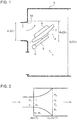
- FIG. 2 is a diagram of a model of flow-path expansion.
- FIG. 3 is a chart showing a relationship between an area ratio and coefficient a of an experimental expression, and
- FIG. 4 is a chart showing a relationship between an area ratio and coefficient ⁇ of an experimental expression.
- a waste-gate valve device 1 diverts a part of exhaust gas, in an engine supercharged by a turbocharger, to adjust a flow rate of exhaust gas entering a turbine.
- the waste-gate valve device 1 includes a turbine housing 3 with a waste-gate channel 2 through which exhaust gas bypasses a turbine (not illustrated), and a waste-gate valve 4 for opening and closing the waste-gate channel 2.
- the waste-gate valve 4 is fixed to a drive shaft 6 via a lever 5 and pivots about an axis passing through the center of the drive shaft 6, whereby the waste-gate channel 2 is opened and closed.
- the waste-gate valve 4 includes a valve body 7 which opens and closes an outlet of the waste-gate channel 2, and a protrusion 8 which is to be housed in the waste-gate channel 2 when the valve body 7 closes the outlet of the waste-gate channel 2.
- Exhaust gas having flowed through the waste-gate channel 2 merges with exhaust gas having flowed through the turbine, at a downstream side of the waste-gate channel 2.
- a flow-path cross-sectional area of exhaust gas flowing through the waste-gate channel 2 expands rapidly. It is known that rapid expansion in a flow-path cross-sectional area of exhaust gas may cause pressure loss, and related findings are disclosed in " Research Report of the R&D Sectional Committee on High-speed Flow of Gas in a Tube" (The Japan Society of Mechanical Engineers, 1978 ).
- an expansion surface pressure P f is proposed as a parameter to represent pressure loss upon flow-path rapid expansion, as illustrated in FIG. 2 .
- the expansion surface pressure P f is expressed by the following experimental expression (expression 3). (Expression 3).
- P r / P 1 1 ⁇ ⁇ M 1 ⁇ M 1 : Mach number
- the expansion surface pressure P f is affected by coefficients a, ⁇ .
- a threshold value of A 1 with respect to A2 can be defined by the following expression 4. (Expression 4).
- a 1 0.2 ⁇ A 2
- FIG. 5 is a schematic diagram of a waste-gate valve device according to the first embodiment.
- FIG. 6 is a diagram of a relationship between an opening degree of a waste-gate valve and a mass flow rate of exhaust gas flowing through a waste-gate channel, in the waste-gate valve device illustrated in FIG. 5 .
- FIG. 7 is a diagram of a relationship between an opening degree of a waste-gate valve and a load applied to a shaft supporting the waste-gate valve, in the waste-gate valve device illustrated in FIG. 5 .
- the waste-gate valve device 11 includes a turbine housing 13 with a waste-gate channel 12 through which exhaust gas bypasses a turbine (not illustrated), and a waste-gate valve 14 for opening and closing the waste-gate channel 12.
- the waste-gate valve 14 is fixed to a drive shaft 16 via a lever 15 and pivots about an axis passing through the center of the drive shaft 16, whereby the waste-gate channel 12 is opened and closed. Accordingly, when the waste-gate valve 14 is open, the flow path is narrower at the side close to the drive shaft 16, and wider at the side remote from the drive shaft 16.
- the diameter D 1 of the waste-gate channel 12 satisfies the above expression 7 while ensuring the maximum flow rate of exhaust gas at the time when the waste-gate valve 14 is fully open. For instance, if the diameter D 2 is 100mm at the merging portion where exhaust gas having flowed through the waste-gate channel 12 and exhaust gas having flowed through the turbine merge (see FIG. 1 ), the diameter D 1 of the waste-gate channel 12 is set to not more than 44.6mm, for instance, to 40mm. Accordingly, the diameter D 1 of the waste-gate channel 12 according to the first embodiment is smaller than that of a conventional case, but the drive shaft 16 for driving the waste-gate valve 14 is disposed on the same position as that in a conventional case. As a result, the waste-gate channel 12 is positioned closer to the drive shaft 16.
- a widened portion 12A is disposed on the outlet of the waste-gate channel 12.
- the widened portion 12A is to increase a flow-path cross-sectional area of the waste-gate channel 12, and the outlet diameter D 3 of the widened portion 12A satisfies the above expression 6.
- the widened portion 12A is gradually widened as illustrated in FIG. 5 .
- the widened portion 12A is gradually widened so as to form a curve (R) in cross section.
- configuration of the widened portion 12A is not limited to this, and may be gradually widened so as to form an oblique line in cross section.
- the waste-gate valve 14 includes a valve body 17 which opens and closes an outlet of the waste-gate channel 12, and a protrusion 18 which is to be housed in the waste-gate channel 12 when the valve body 17 closes the waste-gate channel 12.
- the valve body 17 is formed into a disc shape having a size sufficient to close an outlet of the waste-gate channel 12, which is an outlet of the widened portion 12A.
- the protrusion 18 is formed into a truncated conical shape, and as described above, housed in the waste-gate channel 12 when the valve body 17 closes the outlet of the waste-gate channel 12.
- the protrusion 18 remains in a flow of exhaust gas having flowed the waste-gate channel 12, which improves flow-rate controllability of exhaust gas at the time of slight open.
- the size of the protrusion 18 is set in accordance with the diameter D 1 of the waste-gate channel 12. The larger the protrusion 18 is within a range that the protrusion 18 can be housed in the waste-gate channel 12, the more the flow-rate controllability at the time of slight open of the waste-gate valve 14 improves.
- the lever 15 is formed to be shorter than that in a conventional case in accordance with a decrease in the distance between the waste-gate channel 12 and the drive shaft 16.
- the diameter D 1 of the waste-gate channel 12 satisfies the above described expression 7
- the outlet diameter D 3 of the waste-gate channel 12 satisfies the above described expression 6, which makes it possible to reduce pressure loss. Accordingly, it is possible to reduce the diameter D 1 of the waste-gate channel 12 in accordance with a flow rate increased by reduction of pressure loss. In this way, as illustrated in FIG. 6 , flow-rate controllability of the waste-gate valve device 11 at the time of slight open is improved in accordance with a reduced amount of the diameter D 1 of the waste-gate channel 12.
- the protrusion 18 is housed in the waste-gate channel 12 when the valve body 17 closes the outlet of the waste-gate channel 12, and remains in a flow of exhaust gas when the valve body 17 opens the waste-gate channel 12, which synergistically improves flow-rate controllability at the time of slight open.
- a load applied to the lever 15 is smaller than that in a conventional case, as illustrated in FIG. 7 , which also contributes to improvement of flow-rate controllability.
- FIG. 8 is a schematic diagram of a waste-gate valve device according to the second embodiment of the present invention.
- FIG. 9 is a schematic diagram of the waste-gate valve illustrated in FIG. 8 .
- a waste-gate valve device according to the second embodiment of the present invention is not different from the waste-gate valve device 11 according to the above described first embodiment, except for protrusions 28A, 28B of a waste-gate valve 24.
- the same feature as that in the waste-gate valve device 11 according to the first embodiment is indicated by the same reference numeral and not described in detail.
- the waste-gate valve device 21 includes a pressure-receiving portion (the first protrusion 28A) and a reducing portion (the second protrusion 28B) disposed on the waste-gate valve 24.
- the pressure-receiving portion is to receive more pressure at a drive-shaft side of the waste-gate valve 24 when the waste-gate valve 24 opens.
- the pressure-receiving portion according to the second embodiment includes the first protrusion 28A disposed in a region closer to the drive shaft 16 of a surface facing the waste-gate channel 12, in the waste-gate valve 24.
- the first protrusion 28A is disposed so as to form a recess portion between the first protrusion 28A and the reducing portion (the second protrusion 28B), and has an arc shape as seen from the side of the waste-gate channel, as illustrated in FIG. 9 .
- the pressure-receiving portion (the first protrusion 28A) resists exhaust gas having flowed through the waste-gate channel 12, whereby a pressure is applied to the drive-shaft side of the waste-gate valve 24.
- the reducing portion is to reduce a flow-rate change amount at the time of slight open of the waste-gate valve 24.
- the reducing portion according to the second embodiment includes the second protrusion 18B disposed on a side remote from the drive shaft 16 of a surface facing the waste-gate channel 12, in the waste-gate valve 24.
- the second protrusion 28B has a substantially-halved truncated conical shape, as seen from the side of the waste-gate channel, as illustrated in FIG. 9 .
- the second protrusion 28B has a height not greater than half the diameter D 1 of the waste-gate channel.
- the second protrusion 28B remains in a flow of exhaust gas having flowed the waste-gate channel 12 when the waste-gate valve 24 opens the waste-gate channel 12, which improves flow-rate controllability at the time of slight open of the waste-gate valve 24.
- the waste-gate valve device 21 according to the second embodiment of the present invention is capable of applying more pressure to the drive-shaft side of the waste-gate valve 24 when the waste-gate valve 24 opens, and of reducing a flow-rate change amount at the time of slight open of the waste-gate valve 24. Accordingly, it is possible to improve flow-rate controllability of exhaust gas.
- FIG. 10 is a schematic diagram of a waste-gate valve device according to the third embodiment of the present invention.
- FIG. 11 is a schematic diagram of the waste-gate valve illustrated in FIG. 10 .
- a waste-gate valve device 31 according to the third embodiment of the present invention is not different from the waste-gate valve device 11 according to the above described first embodiment, except for a protrusion 38 of a waste-gate valve 34.
- the same feature as that in the waste-gate valve device 11 according to the first embodiment is indicated by the same reference numeral and not described in detail.
- the waste-gate valve device 31 includes the protrusion 38 integrally including a pressure-receiving portion and a reducing portion disposed on the waste-gate valve 34.
- the pressure-receiving portion is to receive more pressure at the drive shaft of the waste-gate valve 34 when the waste-gate valve 34 opens.
- a side of the protrusion 38, according to the third embodiment of the present invention, closer to the drive shaft 16 forms a pressure-receiving portion.
- the pressure-receiving portion has a halved-cylindrical shape, as seen from the side of the waste-gate channel, as illustrated in FIG. 11 .
- the reducing portion is to reduce a flow-rate change amount at the time of slight open of the waste-gate valve 34.
- a side of the protrusion 38, according to the fourth embodiment, remote from the drive shaft 16 forms a reducing portion.
- the reducing portion has a halved truncated conical shape, as seen from the side of the waste-gate channel, as illustrated in FIG. 11 .
- the protrusion 38 has a height not greater than half the diameter D 1 of the waste-gate channel. This is because, if the height of the protrusion 38 is greater than half the diameter D 1 of the waste-gate channel, an excessive load could be applied to the lever 15 when the waste-gate vale 34 opens. As illustrated in FIG. 10 , the protrusion 38 remains in a flow of exhaust gas having flowed through the waste-gate channel 12 when the waste-gate valve 34 opens the outlet of the waste-gate channel 12, which improves flow-rate controllability at the time of slight open.
- the waste-gate valve device 31 according to the third embodiment of the present invention is capable of applying more pressure to the drive-shaft side of the waste-gate valve 34 when the waste-gate valve 34 opens, and of improving flow-rate controllability at the time of slight open of the waste-gate valve 34.
- FIG. 12 is a schematic diagram of a waste-gate valve device according to the fourth embodiment of the present invention.
- FIG. 13 is a schematic diagram of the waste-gate valve illustrated in FIG. 12 .
- a waste-gate valve device 41 according to the fourth embodiment of the present invention is not different from the waste-gate valve device 11 according to the above described first embodiment, except for protrusions 48A, 48B of a waste-gate valve 44.
- protrusions 48A, 48B of a waste-gate valve 44 the same feature as that in the waste-gate valve device 11 according to the first embodiment is indicated by the same reference numerals and not described in detail.
- the waste-gate valve device 41 includes a pressure-receiving portion (the first protrusion 48A) and a reducing portion (the second protrusion 48B) disposed on the waste-gate valve 44.
- the pressure-receiving portion is to receive more pressure at a drive-shaft side of the waste-gate valve 44 when the waste-gate valve 44 opens.
- the pressure-receiving portion according to the third embodiment of the present invention includes the first protrusion 48A disposed in a region closer to a surface facing the waste-gate channel 12, in the waste-gate valve 44.
- the first protrusion 48A is disposed so as to form a recess portion between the first protrusion 48A and the reducing portion (the second protrusion 48B), and has an arc shape as seen from the side of the waste-gate channel, as illustrated in FIG. 13 .
- the pressure-receiving portion (the first protrusion 48A) resists exhaust gas having flowed through the waste-gate channel 12, whereby a pressure is applied to the drive-shaft side of the waste-gate 24.
- the reducing portion is to reduce a flow-rate change amount at the time of slight open of the waste-gate valve 44.
- the reducing portion according to the fourth embodiment includes the second protrusion 48B disposed on a side remote from the drive shaft 16 of a surface facing the waste-gate channel 12, in the waste-gate valve 44.
- the second protrusion 48B is formed symmetric to the first protrusion 48A with respect to a horizontal line passing through the center of the waste-gate valve 44.
- the second protrusion 48B has an arc shape, as seen from the side of the waste-gate channel, as illustrated in FIG. 13 .
- the second protrusion 48B has a height not greater than half the diameter D 1 of the waste-gate channel.
- the second protrusion 48B remains in a flow of exhaust gas having flowed through the waste-gate channel 12 when the waste-gate valve 44 opens the waste-gate channel 12, which improves flow-rate controllability at the time of slight open.
- the waste-gate valve device 41 according to the fourth embodiment of the present invention is capable of applying more pressure to the drive-shaft side of the waste-gate valve 44 when the waste-gate valve 44 opens, and of improving flow-rate controllability at the time of slight open of the waste-gate valve 44. Further, since the second protrusion 48B is formed symmetric to the first protrusion 48A with respect to a horizontal line passing through the center of the waste-gate valve 44, it is possible to mount the waste-gate valve 44 to the lever 15 regardless of the vertical direction of the waste-gate valve 44.
- FIG. 14 is a schematic diagram of a waste-gate valve device according to the fifth embodiment of the present invention.
- a waste-gate valve device 51 according to the fifth embodiment of the present invention is not different from the waste-gate valve device 11 according to the above described first embodiment, except for a valve body 57 of a waste-gate valve 54.
- the same feature as that in the waste-gate valve device 11 according to the first embodiment is indicated by the same reference numeral and not described in detail.
- the waste-gate valve device 51 is to reduce a load applied to the waste-gate valve 54, and has a rim portion 57a formed to have a shape of a curved surface, the rim portion 57a being disposed on a seating side of the valve body 57. Accordingly, exhaust gas having flowed through the waste-gate channel 12 flows along the rim portion 57a at the seating side of the valve body 57, which reduces a load applied to the waste-gate valve 54.
- the waste-gate valve device 51 according to the fifth embodiment of the present invention is capable of reducing a load applied to the waste-gate valve 54. Accordingly, the waste-gate valve device 51 according to the fifth embodiment of the present invention is capable of improving flow-rate controllability at the time of slight open of the waste-gate valve 54.
- FIG. 15 is a schematic diagram of a waste-gate valve device according to the sixth embodiment of the present invention.
- FIG. 16 is a schematic diagram of the waste-gate valve illustrated in FIG. 15 .
- a waste-gate valve device 61 according to the sixth embodiment of the present invention is not different from the waste-gate valve device 11 according to the above described first embodiment, except for a protrusion 68 of a waste-gate valve 64.
- the same feature as that in the waste-gate valve device 11 according to the first embodiment is indicated by the same reference numeral and not described in detail.
- the waste-gate valve device 61 includes a protrusion 68 disposed on a surface facing the waste-gate valve channel 12, similarly to the waste-gate valve 11 according to the first embodiment.
- the protrusion 68 according to the sixth embodiment of the present invention further includes a recess portion 68a formed on the protrusion 68 of the present embodiment of the present invention.
- the waste-gate valve 64 of the waste-gate valve device 61 according to the sixth embodiment of the present invention can have less weight than the waste-gate valve 14 of the waste-gate valve device 11 according to the above described first embodiment. Further, a drift is caused by the recess portion 68a, which makes it possible to improve flow-rate controllability at the time of slight open of the waste-gate valve 64.
- FIG. 17 is a schematic diagram of a waste-gate valve device according to the seventh embodiment of the present invention.
- a waste-gate valve device 71 according to the seventh embodiment of the present invention is not different from the waste-gate valve device 11 according to the above described first embodiment, except for a protrusion 78 of a waste-gate valve 74.
- the same feature as that of the waste-gate valve according to the first embodiment is indicated by the same reference numeral and not described in detail.
- the waste-gate valve device 71 according to the seventh embodiment of the present invention includes the protrusion 78 disposed on a surface facing the waste-gate valve channel 12, similarly to the waste-gate valve 11 according to the first embodiment.
- the protrusion 78 according to the seventh embodiment of the present invention includes an expanded portion 78a such that a base portion of the protrusion 18 according to the above described first embodiment expands along an inner periphery of the expanded portion 78.
- the waste-gate valve device 71 according to the seventh embodiment of the present invention is capable of avoiding stress concentration on a boundary between the valve body 17 and the protrusion 78.
- FIG. 18 is a schematic diagram of a waste-gate valve device according to the eighth embodiment of the present invention.
- a waste-gate valve device 81 according to the eighth embodiment of the present invention is different from the waste-gate valve 11 according to the above described first embodiment in that a waste-gate valve 84 (valve body 87) is rigidly fixed to a lever 85.
- waste-gate valve device 81 With the waste-gate valve device 81 according to the eighth embodiment of the present invention, it is possible to prevent chattering (extremely high-speed mechanical vibration) of the waste-gate valve 84 while there is a little leakage of exhaust gas.
- FIG. 19 is a schematic diagram of a waste-gate valve device according to the ninth embodiment of the present invention.
- the waste-gate valve device 91 according to the ninth embodiment of the present invention is aimed at improvement of a sealing property (sealability) of the waste-gate valve 94, and the valve body 97 includes an elastic deformation part disposed between an end portion 97A for opening and closing the waste-gate channel 12 and a base portion 97B mounted to a lever 95.
- the elastic deformation part according to the ninth embodiment includes a slit 97C. In this way, the rigidity of the end portion 97A of the valve body 97 is reduced, and the end portion 97A of the valve body 17 warps when the waste-gate valve 94 closes the waste-gate channel 12 (elastic deformation).
- the end portion 97A of the valve body 17 warps when the waste-gate valve 94 closes the waste-gate channel 12, and sealability of the waste-gate valve 94 is ensured.
- FIG. 20 is a schematic diagram of a waste-gate valve device according to the tenth embodiment of the present invention.
- FIG. 21 is a schematic diagram illustrating a drive shaft and a bush supporting the drive shaft.
- a waste-gate valve device 101 includes a turbine housing (not illustrated) with a waste-gate channel through which exhaust gas bypasses a turbine, and a waste-gate valve 104 for opening and closing the waste-gate channel.
- the waste-gate valve 104 is fixed to an end of a drive shaft 106 via a lever 105 and pivots about an axis passing through the center of the drive shaft 106, whereby the waste-gate channel is opened and closed.
- a lever pin 161 is disposed on the other end of the drive shaft 106, and a rod 191 disposed on an actuator 109 is coupled to the lever pin 161. Accordingly, when the actuator 109 is driven, the drive shaft 106 revolves via the rod 191 and the lever pin 161, and the waste-gate valve 104 opens and closes the waste-gate channel.
- the waste-gate valve device 101 may include a tapered surface 163 to prevent uneven contact of the drive shaft 106 with a bush 162 supporting the drive shaft 106.
- the tapered surface 163 is formed to have an inner periphery narrowed at the center in the vertical direction and widened at an upper part and a lower part in the vertical direction so that the drive shaft 106 contacts the tapered surface 163 if tilted.
- the drive shaft 106 is thinned at a stepped portion 164 at the center in the vertical direction, which prevents the drive shaft 106 from being chipped by the narrowed inner periphery.
- the waste-gate valve device 101 may be capable of preventing uneven contact of the drive shaft 106 with the bush 162 supporting the drive shaft 106 and thus preventing generation of an edge surface pressure.
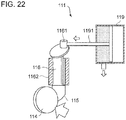
- FIG. 22 is a schematic diagram of a waste-gate valve device according to the eleventh embodiment of the present invention.
- a waste-gate valve device 111 includes a turbine housing (not illustrated) with a waste-gate valve channel through which exhaust gas bypasses a turbine, and a waste-gate valve 114 for opening and closing the waste-gate channel.
- the waste-gate valve 114 is fixed to an end of a drive shaft 116 via a lever 115 and the drive shaft 116 is supported by a bush 1162 disposed on the turbine housing. In this way, the waste-gate valve 114 pivots about an axis passing through the center of the drive shaft 116, and opens and closes the waste-gate channel 12.
- a lever pin 1161 is disposed on the other end of the drive shaft 116, and a rod 1191 disposed on an actuator 119 is coupled to the lever pin 1161.
- the lever pin 1161 and the actuator 119 are disposed so that a pressure direction of exhaust gas applied to the waste-gate valve 114 coincides with an operational direction of the actuator 119.
- the lever pin 1161 and the actuator 119 are disposed so that the waste-gate valve 114 closes the waste-gate channel after the actuator 119 pushes out the rod 1191.
- the waste-gate valve 114 is capable of preventing the drive shaft 116 from inclining in a bush because a pressure direction of exhaust gas applied to the waste-gate valve 114 coincides with an operational direction of the actuator 119. As a result, leakage of exhaust gas outside the turbine housing through clearance between the drive shaft 116 and the bush 1162 is prevented. Further, as a result, the drive shaft 116 and the bush 1162 contact each other via a larger contact area, which makes it possible to achieve an effect to reduce abrasion of the drive shaft 116.
- the waste-gate valve device according to the present invention is capable of improving flow-rate controllability at the time of slight open, and can be suitably applied to a waste-gate valve device which diverts a part of exhaust gas, in a supercharged engine equipped with a turbocharger, to adjust a flow rate of exhaust gas entering the turbine.
Description
- The present invention relates to a waste-gate valve device which diverts a part of exhaust gas, in an engine supercharged by a turbocharger, to adjust a flow rate of exhaust gas entering a turbine.
-
Patent Document 1 discloses a waste-gate valve device with a waste-gate channel bypassing a turbine formed into a tapered shape widened from an inlet toward an outlet, with a valve body (waste-gate valve) for closing the outlet of the waste-gate channel including a protrusion of such a height that the protrusion is flush with an inlet-side wall surface of the waste-gate channel when the waste-gate channel is closed. With the above waste-gate valve device, when the valve body closes the waste-gate channel, the upper surface of the protrusion is flush with the inlet-side wall surface of the waste-gate channel, which makes it possible to reduce turbulence in an exhaust-gas flow at an inlet side of the turbine. Further, with the waste-gate channel having a tapered shape widened from the inlet toward the outlet, a larger gap may be formed between a side surface of the protrusion and an inner peripheral surface of the waste-gate channel even when the valve body is slightly open. Thus, it is possible to achieve a larger opening area for the waste-gate channel. -
Patent Document 2 discloses a waste-gate valve device including a tapered portion at an outlet side of a waste-gate channel bypassing a turbine, so that a flow-path cross-sectional area gradually increases. With the above waste-gate valve device, a pressure-reduction region is formed between the tapered portion and a valve body (waste-gate valve), and the speed of an exhaust-gas flow bypassing the turbine increases in the pressure-reduction region, which makes it possible to reduce a force, especially a moment, applied to the valve body. -
Patent Document 3 discloses a waste-gate valve device with a valve body (waste-gate valve) for closing an outlet of a waste-gate channel, the valve body including a protrusion on a surface adjacent to the waste-gate channel (a seating surface) formed to have a cross section of a "+" shape. With the above waste-gate valve device, it is possible to considerably reduce a negative pressure generated in clearance between the valve body and a valve seat due to turbulence of an exhaust flow flowing through a slight gap (clearance) between the valve body and the valve seat (outlet) at the outlet of the waste-gate channel. Patent Document 4 discloses a waste-gate valve device including a widened portion at an outlet side of a waste-gate channel bypassing a turbine and a protrusion formed on a valve body, so that exhaust gas flow is improved when the valve is opened. -
Patent Document 5 discloses a waste-gate valve device including an arc-shaped protrusion formed on a valve body in order to reduce flow noise. - Last,
Patent Document 6 further discloses a waste-gate valve device including a widened portion at an outlet side of a waste-gate channel. -
- Patent Document 1:
JPH4-95626U - Patent Document 2:
JP2009-203835A - Patent Document 3:
JPS60-78941U - Patent Document 4:
DE 10 2011 108205 A1 - Patent Document 5:
US 2013/305711 A1 - Patent Document 6:
JP S56 171631 U - However, with the above waste-gate valve devices described in
Patent Documents 1 to 3, a flow rate cannot be sufficiently reduced when the valve body is slightly open (hereinafter, referred to as "at the time of slight open"). Furthermore, a great load is applied when the valve body opens, which deteriorates flow-rate controllability. - The present invention was made in view of the above, and an object of the present invention is to provide a waste-gate valve device with high flow-rate controllability at the time of slight open.
- A waste-gate valve device according to the present invention comprises: a turbine housing comprising a waste-gate channel through which exhaust gas bypasses a turbine; and a waste-gate valve configured to open and close an outlet of the waste-gate channel, the waste-gate valve comprising a valve body configured to open and close the outlet of the waste-gate channel, and a protrusion configured to be housed in the waste-gate channel when the valve body closes the outlet of the waste-gate channel. The waste-gate channel ensures a maximum flow rate of exhaust gas at a time when the waste-gate valve is fully open. A flow-path cross-sectional area ratio of the waste-gate channel to a merging portion is not more than 0.2, the merging portion being a portion at which exhaust gas having passed through the turbine merges. A widened portion at which the flow-path cross-sectional area increases is disposed on the outlet of the waste-gate channel.
- According to the present invention, a flow rate of exhaust gas flowing through the waste-gate channel increases, and thus it is possible to reduce a flow-path cross-sectional area of the waste-gate channel in accordance with an amount of the increase. As a result, flow-rate controllability of a flow rate of exhaust gas at the time of slight open of the waste-gate valve improves.
- In an aspect of the present invention, a flow-path diameter D1 of the waste-gate channel satisfies a following
expression 1, with respect to a relationship to a flow-path diameter D2 of the merging portion.
- In this way, it is possible to ensure machining accuracy and to achieve a suitable ratio of a flow-path cross-sectional area of the waste-gate channel to that of the merging portion.
- Further, in an aspect of the present invention, an outlet diameter D3 of the widened portion satisfies a following
expression 2, with respect to a relationship to the flow-path diameter D1 of the waste-gate channel.
- In this way, it is possible to achieve a suitable ratio of a flow-path cross-sectional area of the outlet of the widened portion to that of the waste-gate channel.
- Further, in an aspect of the present invention, the protrusion includes a pressure-receiving portion configured to, when the waste-gate valve is opened, receive a pressure of exhaust gas flowing through the waste-gate channel, in a region close to a shaft supporting the waste-gate valve, and a reducing portion configured to reduce the flow of exhaust gas flowing through the waste-gate channel, in a region remote from the shaft.
- In this way, the pressure-receiving portion can receive a pressure of exhaust gas in a region close to the shaft supporting the waste-gate valve when the waste-gate valve opens, and the reducing portion can reduce a flow of exhaust gas in a region remote from the shaft.
- Further, in an aspect of the present invention, the pressure-receiving portion may be formed in the region close to the shaft, and the reducing portion may be formed in the region remote from the shaft.
- In this way, the pressure-receiving portion can receive a pressure of exhaust gas in a region close to the shaft, and the reducing portion can reduce a flow of exhaust gas in a region remote from the shaft.
- Further, in an aspect of the present invention, the pressure-receiving portion is formed in an arc shape which forms a recess portion between the pressure-receiving portion and the reducing portion.
- In this way, the recess portion can receive a pressure of exhaust gas effectively.
- Further, in an aspect of the present invention, the protrusion includes a recess section which receives exhaust gas flowing through the waste-gate channel. In this way, the recess portion can receive a pressure of exhaust gas effectively.
- In an aspect of the present invention, a base portion of the protrusion may include an expanded portion which expands along an inner periphery of the widened portion.
- In this way, it is possible to avoid stress concentration between the protrusion and the valve body.
- In an aspect of the present invention, the valve body may have a rim portion disposed on a seating side of the valve body and formed into a shape of a curved surface.
- In this way, exhaust gas having flowed through the waste-gate channel flows by the rim portion of the valve body smoothly, which makes it possible to reduce a load applied to the waste-gate valve.
- In an aspect of the present invention, the valve body may comprise an end portion for opening and closing the waste-gate channel, a base portion, and an elastic-deformation portion disposed between the end portion and the base portion and configured to warp the end portion.
- In this way, the end portion of the valve body warps if the waste-gate valve closes an outlet of the waste-gate channel, which makes it possible to ensure sealability of the waste-gate valve.
- In an aspect of the present invention, the waste-gate valve device may further comprise: a drive shaft to which the waste-gate valve is fixed; and a bush supporting the drive shaft, and a tapered surface may be formed on an inner peripheral surface of the bush.
- In this way, it is possible to prevent uneven contact of the drive shaft with the bush, and to prevent generation of an edge surface pressure.
- In an aspect of the present invention, the waste-gate valve device may further comprise: a drive shaft comprising an end to which the waste-gate valve is fixed; a bush supporting the drive shaft; a lever pin disposed on another end of the drive shaft; and an actuator comprising a rod coupled to the lever pin. The lever pin and the actuator are disposed so that a pressure direction applied to the waste-gate valve coincides with an operational direction of the actuator.
- Accordingly, a pressure direction of exhaust gas applied to the waste-gate valve coincides with an operational direction of the actuator. In this way, it is possible to prevent inclination of the drive shaft in the bush. As a result, it is possible to reduce leakage of exhaust gas outside the turbine housing through clearance disposed between the drive shaft and the bush.
- As described above, according to the present invention, pressure loss of exhaust gas flowing through the waste-gate channel is reduced, and a flow rate of exhaust gas increases in accordance with an amount of the reduction. Thus, it is possible to reduce a flow-path cross-sectional area of the waste-gate channel in accordance with an amount of the increase in the flow rate of exhaust gas. As a result, it is possible to achieve good flow-rate controllability at the time of slight open of the waste-gate valve.
-
-
FIG. 1 is a conceptual diagram for describing a waste-gate valve device according to an embodiment of the present invention. -
FIG. 2 is a diagram of an analysis model of flow-path expansion. -
FIG. 3 is a chart showing a relationship between an area ratio and coefficient a of an experimental expression. -
FIG. 4 is a chart showing a relationship between an area ratio and coefficient β of an experimental expression. -
FIG. 5 is a schematic diagram of a waste-gate valve device according to a first embodiment (not claimed). -
FIG. 6 is a diagram of a relationship between an opening degree of a waste-gate valve of the waste-gate valve device illustrated inFIG. 5 and a mass flow rate of exhaust gas flowing through a waste-gate channel. -
FIG. 7 is a diagram of a relationship between an opening degree of a waste-gate valve of the waste-gate valve device illustrated inFIG. 5 and a load applied to a shaft supporting the waste-gate valve. -
FIG. 8 is a schematic diagram of a waste-gate valve device according to a second embodiment according to the present invention. -
FIG. 9 is a schematic diagram of the waste-gate valve illustrated inFIG. 8 . -
FIG. 10 is a schematic diagram of a waste-gate valve device according to a third embodiment according to the present invention. -
FIG. 11 is a schematic diagram of the waste-gate valve illustrated inFIG. 10 . -
FIG. 12 is a schematic diagram of a waste-gate valve device according to a fourth embodiment according to the present invention. -
FIG. 13 is a schematic diagram of the waste-gate valve illustrated inFIG. 12 . -
FIG. 14 is a schematic diagram of a waste-gate valve device according to a fifth embodiment according to the present invention. -
FIG. 15 is a schematic diagram of a waste-gate valve device according to a sixth embodiment according to the present invention. -
FIG. 16 is a schematic diagram of the waste-gate valve illustrated inFIG. 15 . -
FIG. 17 is a schematic diagram of a waste-gate valve device according to a seventh embodiment according to the present invention. -
FIG. 18 is a schematic diagram of a waste-gate valve device according to an eighth embodiment according to the present invention. -
FIG. 19 is a schematic diagram of a waste-gate valve device according to a ninth embodiment according to the present invention. -
FIG. 20 is a schematic diagram of a waste-gate valve device according to a tenth embodiment according to the present invention. -
FIG. 21 is a schematic diagram illustrating a drive shaft and a bush supporting the drive shaft. -
FIG. 22 is a schematic diagram of a waste-gate valve device according to an eleventh embodiment according to the present invention. - With reference to the accompanying drawings, embodiments of a waste-gate valve device according to the present invention will now be specifically described. The present invention should not limited by the following embodiments.
-
FIG. 1 is a conceptual diagram for describing a waste-gate valve according to an embodiment of the present invention.FIG. 2 is a diagram of a model of flow-path expansion.FIG. 3 is a chart showing a relationship between an area ratio and coefficient a of an experimental expression, andFIG. 4 is a chart showing a relationship between an area ratio and coefficient β of an experimental expression. - A
waste-gate valve device 1 diverts a part of exhaust gas, in an engine supercharged by a turbocharger, to adjust a flow rate of exhaust gas entering a turbine. As illustrated inFIG. 1 , thewaste-gate valve device 1 includes aturbine housing 3 with awaste-gate channel 2 through which exhaust gas bypasses a turbine (not illustrated), and a waste-gate valve 4 for opening and closing thewaste-gate channel 2. The waste-gate valve 4 is fixed to adrive shaft 6 via alever 5 and pivots about an axis passing through the center of thedrive shaft 6, whereby thewaste-gate channel 2 is opened and closed. Accordingly, while the waste-gate valve 4 is open, the flow path is narrowed at the side close to thedrive shaft 6, and widened at the side remote from thedrive shaft 6. Further, the waste-gate valve 4 according to the present embodiment includes avalve body 7 which opens and closes an outlet of thewaste-gate channel 2, and aprotrusion 8 which is to be housed in thewaste-gate channel 2 when thevalve body 7 closes the outlet of thewaste-gate channel 2. - Exhaust gas having flowed through the
waste-gate channel 2 merges with exhaust gas having flowed through the turbine, at a downstream side of thewaste-gate channel 2. Thus, a flow-path cross-sectional area of exhaust gas flowing through thewaste-gate channel 2 expands rapidly. It is known that rapid expansion in a flow-path cross-sectional area of exhaust gas may cause pressure loss, and related findings are disclosed in "Research Report of the R&D Sectional Committee on High-speed Flow of Gas in a Tube" (The Japan Society of Mechanical Engineers, 1978). - According to the document, an expansion surface pressure Pf is proposed as a parameter to represent pressure loss upon flow-path rapid expansion, as illustrated in
FIG. 2 . The more rapidly a flow path expands, the smaller the expansion surface pressure Pf is. With a decrease in the value (of expansion surface pressure Pf), greater turbulence occurs in an exhaust-gas flow, and the pressure loss increases. The expansion surface pressure Pf is expressed by the following experimental expression (expression 3).
(Expression 3).
- Meanwhile, as shown in the
expression 1, the expansion surface pressure Pf is affected by coefficients a, β. As shown inFIGs. 3 and 4 , coefficient a and coefficient β of the experimental expression change in accordance with an area ratio ψ, and rapidly changes at an area ratio ψ (A1/A2) = 0.22 and below. Accordingly, the expansion surface pressure Pf changes considerably at an area ratio ψ = 0.22 and below. - Even if a widened
portion 2A is provided at the outlet of thewaste-gate channel 2 having an area ratio ψ (A1/A2) of 0.22 to expand the flow path, the area ratio ψ (A3/A2) would be 0.22 or higher. Thus, as illustrated inFIG. 1 , an effect to expand the flow path (to reduce pressure loss) is reduced. - Further, if the minimum expansion is set to be 0.5mm in diameter and a difference in area ratio of at least 0.02 (A1/A2 - A3/A2) is ensured, taking account of machining accuracy, a threshold value of A1 with respect to A2 can be defined by the following expression 4.
(Expression 4).
- Herein, the number in the expression 4 is 0.2 and not 0.22 because the position of an inflexion point is 0.22 as illustrated in
FIGs. 3 and 4 , and a difference in area ratio at a rapid-change region, which is approximately one-tenth (0.22 × 0.1 = 0.02), is subtracted. - With the expression 4 converted into a flow-path diameter, the diameter D1 can be obtained from the following
expression 5.
(Expression 5)
- Here, given that A1 = (Di/2) ^2 × π, A2 = (D2/2) ^2 × π, and A3 = (D3/2) ^2 ×π, the following expressions are satisfied:


- Accordingly, a relationship (expansion width) of the outlet diameter D3 of the widened
portion 2A to D1 can be expressed by the followingexpression 6.
(Expression 6)
- Further as illustrated in
FIGs. 3 and 4 , since the area ratio ψ (A1/A2) at the inflexion point is 0.22, if converted into a flow-path diameter, an expression of D1/D2 = 0.469 would be satisfied, which can be also expressed as an expression of D1 = 0.469D2. Further, since the minimum expansion width is set to 0.5mm taking account of machining accuracy as described above, the diameter D1 of thewaste-gate channel 2 is further reduced by 0.5mm. Accordingly, the diameter D1 of thewaste-gate channel 2 is required to satisfy thefollowing expression 7.
(Expression 7)
- Summarizing the above, for the
waste-gate valve device 1 satisfying an expression of D1 < D2, where D1 is the diameter of thewaste-gate channel 2 and D2 is the diameter of the merging portion, rapid expansion of a flow path is suppressed and pressure loss is reduced if D1, the diameter of thewaste-gate channel 2, satisfies an expression of D1 ≤ 0.47D2 - 0.5mm, and D3, the outlet diameter of the widenedportion 2A, satisfies an expression of D3 ≥ 1.049D1. Accordingly, it is possible to reduce the diameter D1 of thewaste-gate channel 2 in accordance with a flow rate increased by reduction of pressure loss. In this way, flow-rate controllability of thewaste-gate valve device 1 is improved in accordance with a reduced amount of the diameter D1 of thewaste-gate channel 2. - (First embodiment, not claimed)
FIG. 5 is a schematic diagram of a waste-gate valve device according to the first embodiment.FIG. 6 is a diagram of a relationship between an opening degree of a waste-gate valve and a mass flow rate of exhaust gas flowing through a waste-gate channel, in the waste-gate valve device illustrated inFIG. 5 .FIG. 7 is a diagram of a relationship between an opening degree of a waste-gate valve and a load applied to a shaft supporting the waste-gate valve, in the waste-gate valve device illustrated inFIG. 5 . - As illustrated in
FIG. 5 , thewaste-gate valve device 11 according to the first embodiment includes aturbine housing 13 with awaste-gate channel 12 through which exhaust gas bypasses a turbine (not illustrated), and awaste-gate valve 14 for opening and closing thewaste-gate channel 12. Thewaste-gate valve 14 is fixed to adrive shaft 16 via alever 15 and pivots about an axis passing through the center of thedrive shaft 16, whereby thewaste-gate channel 12 is opened and closed. Accordingly, when thewaste-gate valve 14 is open, the flow path is narrower at the side close to thedrive shaft 16, and wider at the side remote from thedrive shaft 16. - The diameter D1 of the
waste-gate channel 12 satisfies theabove expression 7 while ensuring the maximum flow rate of exhaust gas at the time when thewaste-gate valve 14 is fully open. For instance, if the diameter D2 is 100mm at the merging portion where exhaust gas having flowed through thewaste-gate channel 12 and exhaust gas having flowed through the turbine merge (seeFIG. 1 ), the diameter D1 of thewaste-gate channel 12 is set to not more than 44.6mm, for instance, to 40mm. Accordingly, the diameter D1 of thewaste-gate channel 12 according to the first embodiment is smaller than that of a conventional case, but thedrive shaft 16 for driving thewaste-gate valve 14 is disposed on the same position as that in a conventional case. As a result, thewaste-gate channel 12 is positioned closer to thedrive shaft 16. - A widened
portion 12A is disposed on the outlet of thewaste-gate channel 12. The widenedportion 12A is to increase a flow-path cross-sectional area of thewaste-gate channel 12, and the outlet diameter D3 of the widenedportion 12A satisfies theabove expression 6. For instance, if the diameter D1 of thewaste-gate channel 12 is 40mm, the outlet diameter D3 of the widenedportion 12A is set to at least 41.96mm, for instance, to 42mm. Accordingly, the widenedportion 12A is gradually widened as illustrated inFIG. 5 . In the example illustrated inFIG. 5 , the widenedportion 12A is gradually widened so as to form a curve (R) in cross section. However, configuration of the widenedportion 12A is not limited to this, and may be gradually widened so as to form an oblique line in cross section. - Further, the
waste-gate valve 14 according to the first embodiment includes avalve body 17 which opens and closes an outlet of thewaste-gate channel 12, and aprotrusion 18 which is to be housed in thewaste-gate channel 12 when thevalve body 17 closes thewaste-gate channel 12. Thevalve body 17 is formed into a disc shape having a size sufficient to close an outlet of thewaste-gate channel 12, which is an outlet of the widenedportion 12A. Theprotrusion 18 is formed into a truncated conical shape, and as described above, housed in thewaste-gate channel 12 when thevalve body 17 closes the outlet of thewaste-gate channel 12. Also, when thevalve body 17 opens thewaste-gate channel 12, theprotrusion 18 remains in a flow of exhaust gas having flowed thewaste-gate channel 12, which improves flow-rate controllability of exhaust gas at the time of slight open. Thus, the size of theprotrusion 18 is set in accordance with the diameter D1 of thewaste-gate channel 12. The larger theprotrusion 18 is within a range that theprotrusion 18 can be housed in thewaste-gate channel 12, the more the flow-rate controllability at the time of slight open of thewaste-gate valve 14 improves. - Further, whereas the
waste-gate valve 14 is connected to thedrive shaft 16 for driving thewaste-gate valve 14 via alever 15, similarly to a conventional case, thelever 15 is formed to be shorter than that in a conventional case in accordance with a decrease in the distance between thewaste-gate channel 12 and thedrive shaft 16. - In the
waste-gate valve device 11 according to the present embodiment of the present invention, the diameter D1 of thewaste-gate channel 12 satisfies the above describedexpression 7, and the outlet diameter D3 of thewaste-gate channel 12 satisfies the above describedexpression 6, which makes it possible to reduce pressure loss. Accordingly, it is possible to reduce the diameter D1 of thewaste-gate channel 12 in accordance with a flow rate increased by reduction of pressure loss. In this way, as illustrated inFIG. 6 , flow-rate controllability of thewaste-gate valve device 11 at the time of slight open is improved in accordance with a reduced amount of the diameter D1 of thewaste-gate channel 12. Further, theprotrusion 18 is housed in thewaste-gate channel 12 when thevalve body 17 closes the outlet of thewaste-gate channel 12, and remains in a flow of exhaust gas when thevalve body 17 opens thewaste-gate channel 12, which synergistically improves flow-rate controllability at the time of slight open. Further, since thelever 15 is shorter than that in a conventional case, a load applied to thelever 15 is smaller than that in a conventional case, as illustrated inFIG. 7 , which also contributes to improvement of flow-rate controllability. -
FIG. 8 is a schematic diagram of a waste-gate valve device according to the second embodiment of the present invention.FIG. 9 is a schematic diagram of the waste-gate valve illustrated inFIG. 8 . A waste-gate valve device according to the second embodiment of the present invention is not different from thewaste-gate valve device 11 according to the above described first embodiment, except forprotrusions waste-gate valve 24. Thus, the same feature as that in thewaste-gate valve device 11 according to the first embodiment is indicated by the same reference numeral and not described in detail. - As illustrated in
FIGs. 8 and 9 , thewaste-gate valve device 21 according to the second embodiment of the present invention includes a pressure-receiving portion (thefirst protrusion 28A) and a reducing portion (thesecond protrusion 28B) disposed on thewaste-gate valve 24. - The pressure-receiving portion is to receive more pressure at a drive-shaft side of the
waste-gate valve 24 when thewaste-gate valve 24 opens. As illustrated inFIG. 8 , the pressure-receiving portion according to the second embodiment includes thefirst protrusion 28A disposed in a region closer to thedrive shaft 16 of a surface facing thewaste-gate channel 12, in thewaste-gate valve 24. Thefirst protrusion 28A is disposed so as to form a recess portion between thefirst protrusion 28A and the reducing portion (thesecond protrusion 28B), and has an arc shape as seen from the side of the waste-gate channel, as illustrated inFIG. 9 . The pressure-receiving portion (thefirst protrusion 28A) resists exhaust gas having flowed through thewaste-gate channel 12, whereby a pressure is applied to the drive-shaft side of thewaste-gate valve 24. - The reducing portion is to reduce a flow-rate change amount at the time of slight open of the
waste-gate valve 24. As illustrated inFIG. 8 , the reducing portion according to the second embodiment includes the second protrusion 18B disposed on a side remote from thedrive shaft 16 of a surface facing thewaste-gate channel 12, in thewaste-gate valve 24. Thesecond protrusion 28B has a substantially-halved truncated conical shape, as seen from the side of the waste-gate channel, as illustrated inFIG. 9 . Thesecond protrusion 28B has a height not greater than half the diameter D1 of the waste-gate channel. This is because, if the height of thesecond protrusion 28B is greater than half the diameter D1 of the waste-gate channel, an excessive load could be applied to thelever 15 when thewaste-gate valve 24 opens. As illustrated inFIG. 8 , thesecond protrusion 28B remains in a flow of exhaust gas having flowed thewaste-gate channel 12 when thewaste-gate valve 24 opens thewaste-gate channel 12, which improves flow-rate controllability at the time of slight open of thewaste-gate valve 24. - The
waste-gate valve device 21 according to the second embodiment of the present invention is capable of applying more pressure to the drive-shaft side of thewaste-gate valve 24 when thewaste-gate valve 24 opens, and of reducing a flow-rate change amount at the time of slight open of thewaste-gate valve 24. Accordingly, it is possible to improve flow-rate controllability of exhaust gas. -
FIG. 10 is a schematic diagram of a waste-gate valve device according to the third embodiment of the present invention.FIG. 11 is a schematic diagram of the waste-gate valve illustrated inFIG. 10 . Awaste-gate valve device 31 according to the third embodiment of the present invention is not different from thewaste-gate valve device 11 according to the above described first embodiment, except for aprotrusion 38 of awaste-gate valve 34. Thus, the same feature as that in thewaste-gate valve device 11 according to the first embodiment is indicated by the same reference numeral and not described in detail. - As illustrated in
FIGs. 10 and 11 , thewaste-gate valve device 31 according to the present embodiment of the present invention includes theprotrusion 38 integrally including a pressure-receiving portion and a reducing portion disposed on thewaste-gate valve 34. - The pressure-receiving portion is to receive more pressure at the drive shaft of the
waste-gate valve 34 when thewaste-gate valve 34 opens. A side of theprotrusion 38, according to the third embodiment of the present invention, closer to thedrive shaft 16 forms a pressure-receiving portion. The pressure-receiving portion has a halved-cylindrical shape, as seen from the side of the waste-gate channel, as illustrated inFIG. 11 . - The reducing portion is to reduce a flow-rate change amount at the time of slight open of the
waste-gate valve 34. A side of theprotrusion 38, according to the fourth embodiment, remote from thedrive shaft 16 forms a reducing portion. The reducing portion has a halved truncated conical shape, as seen from the side of the waste-gate channel, as illustrated inFIG. 11 . - The
protrusion 38 has a height not greater than half the diameter D1 of the waste-gate channel. This is because, if the height of theprotrusion 38 is greater than half the diameter D1 of the waste-gate channel, an excessive load could be applied to thelever 15 when thewaste-gate vale 34 opens. As illustrated inFIG. 10 , theprotrusion 38 remains in a flow of exhaust gas having flowed through thewaste-gate channel 12 when thewaste-gate valve 34 opens the outlet of thewaste-gate channel 12, which improves flow-rate controllability at the time of slight open. - The
waste-gate valve device 31 according to the third embodiment of the present invention is capable of applying more pressure to the drive-shaft side of thewaste-gate valve 34 when thewaste-gate valve 34 opens, and of improving flow-rate controllability at the time of slight open of thewaste-gate valve 34. -
FIG. 12 is a schematic diagram of a waste-gate valve device according to the fourth embodiment of the present invention.FIG. 13 is a schematic diagram of the waste-gate valve illustrated inFIG. 12 . Awaste-gate valve device 41 according to the fourth embodiment of the present invention is not different from thewaste-gate valve device 11 according to the above described first embodiment, except forprotrusions waste-gate valve 44. Thus, the same feature as that in thewaste-gate valve device 11 according to the first embodiment is indicated by the same reference numerals and not described in detail. - As illustrated in
FIGs. 12 and 13 , thewaste-gate valve device 41 according to the fourth embodiment of the present invention includes a pressure-receiving portion (thefirst protrusion 48A) and a reducing portion (thesecond protrusion 48B) disposed on thewaste-gate valve 44. - The pressure-receiving portion is to receive more pressure at a drive-shaft side of the
waste-gate valve 44 when thewaste-gate valve 44 opens. As illustrated inFIG. 12 , the pressure-receiving portion according to the third embodiment of the present invention includes thefirst protrusion 48A disposed in a region closer to a surface facing thewaste-gate channel 12, in thewaste-gate valve 44. Thefirst protrusion 48A is disposed so as to form a recess portion between thefirst protrusion 48A and the reducing portion (thesecond protrusion 48B), and has an arc shape as seen from the side of the waste-gate channel, as illustrated inFIG. 13 . The pressure-receiving portion (thefirst protrusion 48A) resists exhaust gas having flowed through thewaste-gate channel 12, whereby a pressure is applied to the drive-shaft side of thewaste-gate 24. - The reducing portion is to reduce a flow-rate change amount at the time of slight open of the
waste-gate valve 44. As illustrated inFIG. 12 , the reducing portion according to the fourth embodiment includes thesecond protrusion 48B disposed on a side remote from thedrive shaft 16 of a surface facing thewaste-gate channel 12, in thewaste-gate valve 44. Thesecond protrusion 48B is formed symmetric to thefirst protrusion 48A with respect to a horizontal line passing through the center of thewaste-gate valve 44. Thus, thesecond protrusion 48B has an arc shape, as seen from the side of the waste-gate channel, as illustrated inFIG. 13 . Thesecond protrusion 48B has a height not greater than half the diameter D1 of the waste-gate channel. This is because, if the height of thesecond protrusion 48B is greater than half the diameter D1 of the waste-gate channel, an excessive load could be applied to thelever 15 when thewaste-gate valve 44 opens. As illustrated inFIG. 13 , thesecond protrusion 48B remains in a flow of exhaust gas having flowed through thewaste-gate channel 12 when thewaste-gate valve 44 opens thewaste-gate channel 12, which improves flow-rate controllability at the time of slight open. - The
waste-gate valve device 41 according to the fourth embodiment of the present invention is capable of applying more pressure to the drive-shaft side of thewaste-gate valve 44 when thewaste-gate valve 44 opens, and of improving flow-rate controllability at the time of slight open of thewaste-gate valve 44. Further, since thesecond protrusion 48B is formed symmetric to thefirst protrusion 48A with respect to a horizontal line passing through the center of thewaste-gate valve 44, it is possible to mount thewaste-gate valve 44 to thelever 15 regardless of the vertical direction of thewaste-gate valve 44. -
FIG. 14 is a schematic diagram of a waste-gate valve device according to the fifth embodiment of the present invention. Awaste-gate valve device 51 according to the fifth embodiment of the present invention is not different from thewaste-gate valve device 11 according to the above described first embodiment, except for avalve body 57 of awaste-gate valve 54. Thus, the same feature as that in thewaste-gate valve device 11 according to the first embodiment is indicated by the same reference numeral and not described in detail. - As illustrated in
FIG. 14 , thewaste-gate valve device 51 according to the fifth embodiment of the present invention is to reduce a load applied to thewaste-gate valve 54, and has arim portion 57a formed to have a shape of a curved surface, therim portion 57a being disposed on a seating side of thevalve body 57. Accordingly, exhaust gas having flowed through thewaste-gate channel 12 flows along therim portion 57a at the seating side of thevalve body 57, which reduces a load applied to thewaste-gate valve 54. - The
waste-gate valve device 51 according to the fifth embodiment of the present invention is capable of reducing a load applied to thewaste-gate valve 54. Accordingly, thewaste-gate valve device 51 according to the fifth embodiment of the present invention is capable of improving flow-rate controllability at the time of slight open of thewaste-gate valve 54. -
FIG. 15 is a schematic diagram of a waste-gate valve device according to the sixth embodiment of the present invention.FIG. 16 is a schematic diagram of the waste-gate valve illustrated inFIG. 15 . Awaste-gate valve device 61 according to the sixth embodiment of the present invention is not different from thewaste-gate valve device 11 according to the above described first embodiment, except for aprotrusion 68 of awaste-gate valve 64. Thus, the same feature as that in thewaste-gate valve device 11 according to the first embodiment is indicated by the same reference numeral and not described in detail. - As illustrated in
FIGs. 15 and16 , thewaste-gate valve device 61 according to the sixth embodiment of the present invention includes aprotrusion 68 disposed on a surface facing thewaste-gate valve channel 12, similarly to thewaste-gate valve 11 according to the first embodiment. Theprotrusion 68 according to the sixth embodiment of the present invention further includes arecess portion 68a formed on theprotrusion 68 of the present embodiment of the present invention. - The
waste-gate valve 64 of thewaste-gate valve device 61 according to the sixth embodiment of the present invention can have less weight than thewaste-gate valve 14 of thewaste-gate valve device 11 according to the above described first embodiment. Further, a drift is caused by therecess portion 68a, which makes it possible to improve flow-rate controllability at the time of slight open of thewaste-gate valve 64. -
FIG. 17 is a schematic diagram of a waste-gate valve device according to the seventh embodiment of the present invention. Awaste-gate valve device 71 according to the seventh embodiment of the present invention is not different from thewaste-gate valve device 11 according to the above described first embodiment, except for aprotrusion 78 of awaste-gate valve 74. Thus, the same feature as that of the waste-gate valve according to the first embodiment is indicated by the same reference numeral and not described in detail. - As illustrated in
FIG. 17 , thewaste-gate valve device 71 according to the seventh embodiment of the present invention includes theprotrusion 78 disposed on a surface facing thewaste-gate valve channel 12, similarly to thewaste-gate valve 11 according to the first embodiment. Theprotrusion 78 according to the seventh embodiment of the present invention includes an expandedportion 78a such that a base portion of theprotrusion 18 according to the above described first embodiment expands along an inner periphery of the expandedportion 78. - The
waste-gate valve device 71 according to the seventh embodiment of the present invention is capable of avoiding stress concentration on a boundary between thevalve body 17 and theprotrusion 78. -
FIG. 18 is a schematic diagram of a waste-gate valve device according to the eighth embodiment of the present invention. As illustrated inFIG. 18 , awaste-gate valve device 81 according to the eighth embodiment of the present invention is different from thewaste-gate valve 11 according to the above described first embodiment in that a waste-gate valve 84 (valve body 87) is rigidly fixed to alever 85. - With the
waste-gate valve device 81 according to the eighth embodiment of the present invention, it is possible to prevent chattering (extremely high-speed mechanical vibration) of thewaste-gate valve 84 while there is a little leakage of exhaust gas. -
FIG. 19 is a schematic diagram of a waste-gate valve device according to the ninth embodiment of the present invention. As illustrated inFIG. 19 , thewaste-gate valve device 91 according to the ninth embodiment of the present invention is aimed at improvement of a sealing property (sealability) of thewaste-gate valve 94, and thevalve body 97 includes an elastic deformation part disposed between anend portion 97A for opening and closing thewaste-gate channel 12 and abase portion 97B mounted to alever 95. The elastic deformation part according to the ninth embodiment includes aslit 97C. In this way, the rigidity of theend portion 97A of thevalve body 97 is reduced, and theend portion 97A of thevalve body 17 warps when thewaste-gate valve 94 closes the waste-gate channel 12 (elastic deformation). - With the
waste-gate valve 91 according to the ninth embodiment of the present invention, theend portion 97A of thevalve body 17 warps when thewaste-gate valve 94 closes thewaste-gate channel 12, and sealability of thewaste-gate valve 94 is ensured. -
FIG. 20 is a schematic diagram of a waste-gate valve device according to the tenth embodiment of the present invention.FIG. 21 is a schematic diagram illustrating a drive shaft and a bush supporting the drive shaft. As illustrated inFIG. 20 , awaste-gate valve device 101 includes a turbine housing (not illustrated) with a waste-gate channel through which exhaust gas bypasses a turbine, and awaste-gate valve 104 for opening and closing the waste-gate channel. Thewaste-gate valve 104 is fixed to an end of adrive shaft 106 via alever 105 and pivots about an axis passing through the center of thedrive shaft 106, whereby the waste-gate channel is opened and closed. Alever pin 161 is disposed on the other end of thedrive shaft 106, and arod 191 disposed on anactuator 109 is coupled to thelever pin 161. Accordingly, when theactuator 109 is driven, thedrive shaft 106 revolves via therod 191 and thelever pin 161, and thewaste-gate valve 104 opens and closes the waste-gate channel. - Meanwhile, the
waste-gate valve device 101 according to the tenth embodiment of the present invention may include atapered surface 163 to prevent uneven contact of thedrive shaft 106 with abush 162 supporting thedrive shaft 106. Specifically, as illustrated inFIG. 21 , thetapered surface 163 is formed to have an inner periphery narrowed at the center in the vertical direction and widened at an upper part and a lower part in the vertical direction so that thedrive shaft 106 contacts the taperedsurface 163 if tilted. Further, thedrive shaft 106 is thinned at a steppedportion 164 at the center in the vertical direction, which prevents thedrive shaft 106 from being chipped by the narrowed inner periphery. - The
waste-gate valve device 101 according to the tenth embodiment of the present invention may be capable of preventing uneven contact of thedrive shaft 106 with thebush 162 supporting thedrive shaft 106 and thus preventing generation of an edge surface pressure. -
FIG. 22 is a schematic diagram of a waste-gate valve device according to the eleventh embodiment of the present invention. As illustrated inFIG. 22 , awaste-gate valve device 111 includes a turbine housing (not illustrated) with a waste-gate valve channel through which exhaust gas bypasses a turbine, and awaste-gate valve 114 for opening and closing the waste-gate channel. Thewaste-gate valve 114 is fixed to an end of adrive shaft 116 via alever 115 and thedrive shaft 116 is supported by abush 1162 disposed on the turbine housing. In this way, thewaste-gate valve 114 pivots about an axis passing through the center of thedrive shaft 116, and opens and closes thewaste-gate channel 12. Alever pin 1161 is disposed on the other end of thedrive shaft 116, and arod 1191 disposed on anactuator 119 is coupled to thelever pin 1161. Thelever pin 1161 and theactuator 119 are disposed so that a pressure direction of exhaust gas applied to thewaste-gate valve 114 coincides with an operational direction of theactuator 119. Specifically, as illustrated inFIG. 22 , thelever pin 1161 and theactuator 119 are disposed so that thewaste-gate valve 114 closes the waste-gate channel after theactuator 119 pushes out therod 1191. - As described above, with the
lever pin 1161 and theactuator 1191 being disposed so that thewaste-gate valve 114 closes the waste-gate channel when theactuator 119 pushes out therod 1191, a pressure direction of exhaust gas applied to thewaste-gate valve 114 coincides with an operational direction of theactuator 119. In this way, it is possible to prevent inclination of thedrive shaft 1161 in a bush. As a result, it is possible to reduce leakage of exhaust gas outside the turbine housing through clearance between thedrive shaft 116 and thebush 1162. - As described above, the
waste-gate valve 114 according to an embodiment of the present invention is capable of preventing thedrive shaft 116 from inclining in a bush because a pressure direction of exhaust gas applied to thewaste-gate valve 114 coincides with an operational direction of theactuator 119. As a result, leakage of exhaust gas outside the turbine housing through clearance between thedrive shaft 116 and thebush 1162 is prevented. Further, as a result, thedrive shaft 116 and thebush 1162 contact each other via a larger contact area, which makes it possible to achieve an effect to reduce abrasion of thedrive shaft 116. - As described above, the waste-gate valve device according to the present invention is capable of improving flow-rate controllability at the time of slight open, and can be suitably applied to a waste-gate valve device which diverts a part of exhaust gas, in a supercharged engine equipped with a turbocharger, to adjust a flow rate of exhaust gas entering the turbine.
-
- 1
- Waste-gate valve device
- 2
- Waste-gate channel
- 2A
- Widened portion
- 3
- Turbine housing
- 4
- Waste-gate valve
- 5
- Lever
- 6
- Drive shaft
- 7
- Valve body
- 8
- Protrusion
- D1
- Diameter of waste-gate channel
- D2
- Flow path diameter of merging portion
- D3
- Outlet diameter of waste-gate channel
- Pf
- Expansion surface pressure
- 11
- Waste-gate valve device
- 12
- Waste-gate channel
- 12A
- Widened portion
- 13
- Turbine housing
- 14
- Waste-gate valve
- 15
- Lever
- 16
- Drive shaft
- 17
- Valve body
- 18
- Protrusion
- 21
- Waste-gate valve device
- 24
- Waste-gate valve
- 28A
- First protrusion
- 28B
- Second protrusion
- 31
- Waste-gate valve device
- 34
- Waste-gate valve
- 38
- Protrusion
- 41
- Waste-gate valve device
- 44
- Waste-gate valve
- 48A
- First protrusion (pressure-receiving portion)
- 48B
- Second protrusion (reducing portion)
- 51
- Waste-gate valve device
- 54
- Waste-gate valve
- 57
- Valve body
- 57a
- Rim portion
- 61
- Waste-gate valve device
- 64
- Waste-gate valve
- 68
- Protrusion
- 68a
- Recess portion
- 71
- Waste-gate valve device
- 74
- Waste-gate valve
- 78
- Protrusion
- 78a
- Expanded portion
- 81
- Waste-gate valve device
- 84
- Waste-gate valve
- 85
- Lever
- 87
- Valve body
- 91
- Waste-gate valve device
- 94
- Waste-gate valve
- 95
- Lever
- 97
- Valve body
- 97A
- End portion
- 97B
- Base portion
- 97C
- Slit
- 101
- Waste-gate valve device
- 104
- Waste-gate valve
- 105
- Lever
- 106
- Drive shaft
- 161
- Lever pin
- 162
- Bush
- 163
- Tapered surface
- 164
- Stepped portion
- 109
- Actuator
- 191
- Rod
- 111
- Waste-gate valve device
- 114
- Waste-gate valve
- 115
- Lever
- 116
- Drive shaft
- 1161
- Lever pin
- 1162
- Bush
- 119
- Actuator
- 1191
- Rod
Claims (8)
- A waste-gate valve device (1), comprising:a turbine housing (3) comprising a waste-gate channel through which exhaust gas bypasses a turbine; anda waste-gate valve (4) configured to open and close an outlet of the waste-gate channel, the waste-gate valve comprisinga valve body (7) configured to open and close the outlet of the waste-gate channel, anda protrusion (8) configured to be housed in the waste-gate channel when the valve body closes the outlet of the waste-gate channel,wherein the waste-gate channel ensures a maximum flow rate of exhaust gas at a time when the waste-gate valve is fully open,wherein a flow-path cross-sectional area ratio of the waste-gate channel to a merging portion is not more than 0.2, the merging portion being a portion at which exhaust gas having passed through the turbine merges,wherein a widened portion (12A) is disposed on the outlet of the waste-gate channel the widened portion being gradually widened so as to form a curve in cross section and having a flow-path cross sectional area which gradually increases,wherein the protrusion includesa pressure-receiving portion (28A, 48A) configured to, when the waste-gate valve is opened, receive a pressure of exhaust gas flowing through the waste-gate channel, in a region close to a shaft supporting the waste-gate valve, anda reducing portion (28B, 48B) configured to reduce the flow of exhaust gas flowing through the waste-gate channel, in a region remote from the shaft, whereina flow-path diameter D1 of the waste-gate channel satisfies a following expression 1, with respect to a relationship to a flow-path diameter D2 of the merging portion,


wherein the pressure-receiving portion (28A, 48A) is formed in an arc shape which forms a recess portion between the pressure-receiving portion (28A, 48A) and the reducing portion (28B, 48B), as seen from the side of the waste-gate channel. - The waste-gate valve device according to claim 1,
wherein the reducing portion (28B) has a substantially-halved truncated conical shape. - The waste-gate valve device according to claim 1 or 2,
wherein the reducing portion (48B) has an arc shape, as seen from the side of the waste-gate channel. - The waste-gate valve device according to any one of claims 1 to 3,
wherein a base portion of the protrusion includes an expanded portion which expands along an inner periphery of the widened portion. - The waste-gate valve device according to any one of claims 1 to 4,
wherein the valve body has a rim portion disposed on a seating side of the valve body and formed into a shape of a curved surface. - The waste-gate valve device according to any one of claims 1 to 5,
wherein the valve body comprises
an end portion for opening and closing the waste-gate channel,
a base portion, and
an elastic-deformation portion (97C) disposed between the end portion and the base portion and configured to warp the end portion. - The waste-gate valve device according to any one of claims 1 to 6, further comprising:a drive shaft (106) to which the waste-gate valve is fixed; anda bush (162) supporting the drive shaft,wherein a tapered surface (153) is formed on an inner peripheral surface of the bush.
- The waste-gate valve device according to any one of claims 1 to 7, further comprising:a drive shaft (116) comprising an end to which the waste-gate valve is fixed;a bush (1162) supporting the drive shaft;a lever pin (1161) disposed on another end of the drive shaft; andan actuator (119) comprising a rod coupled to the lever pin,wherein the lever pin and the actuator are disposed so that a pressure direction applied to the waste-gate valve coincides with an operational direction of the actuator.
Applications Claiming Priority (1)
| Application Number | Priority Date | Filing Date | Title |
|---|---|---|---|
| PCT/JP2013/084672 WO2015097786A1 (en) | 2013-12-25 | 2013-12-25 | Waste gate valve device |
Publications (3)
| Publication Number | Publication Date |
|---|---|
| EP3088697A1 EP3088697A1 (en) | 2016-11-02 |
| EP3088697A4 EP3088697A4 (en) | 2016-12-21 |
| EP3088697B1 true EP3088697B1 (en) | 2018-08-22 |
Family
ID=53477726
Family Applications (1)
| Application Number | Title | Priority Date | Filing Date |
|---|---|---|---|
| EP13900040.0A Active EP3088697B1 (en) | 2013-12-25 | 2013-12-25 | Waste gate valve device |
Country Status (5)
| Country | Link |
|---|---|
| US (1) | US10072564B2 (en) |
| EP (1) | EP3088697B1 (en) |
| JP (1) | JP6167186B2 (en) |
| CN (1) | CN105723066B (en) |
| WO (1) | WO2015097786A1 (en) |
Families Citing this family (9)
| Publication number | Priority date | Publication date | Assignee | Title |
|---|---|---|---|---|
| DE102015212381B4 (en) * | 2015-07-02 | 2017-10-12 | Continental Automotive Gmbh | Exhaust gas turbocharger with a wastegate device |
| DE102016214843B4 (en) * | 2016-08-10 | 2020-06-18 | Continental Automotive Gmbh | Bypass valve with flap apron for an exhaust gas turbocharger and exhaust gas turbocharger with such a bypass valve |
| JP6834882B2 (en) * | 2017-09-22 | 2021-02-24 | トヨタ自動車株式会社 | Turbocharger |
| CN108591494B (en) * | 2018-04-10 | 2020-04-10 | 中国北方发动机研究所(天津) | Method for designing valve core of multi-section mixed regulating valve |
| DE102018220965A1 (en) | 2018-12-04 | 2020-06-04 | Borgwarner Inc. | Flap arrangement for a turbine of an exhaust gas turbocharger |
| US10533491B1 (en) | 2019-03-25 | 2020-01-14 | Borgwarner Inc. | Connecting assembly and turbocharger including the connecting assembly |
| CN113123857B (en) * | 2019-12-30 | 2022-08-09 | 上海汽车集团股份有限公司 | Turbine box exhaust gas bypass device |
| JP7396254B2 (en) * | 2020-11-18 | 2023-12-12 | トヨタ自動車株式会社 | turbo charger |
| JPWO2023037453A1 (en) | 2021-09-08 | 2023-03-16 |
Citations (2)
| Publication number | Priority date | Publication date | Assignee | Title |
|---|---|---|---|---|
| GB2066365A (en) * | 1979-12-27 | 1981-07-08 | Nissan Motor | Turbocharger for internal combustion engine |
| JPS56171631U (en) * | 1980-05-23 | 1981-12-18 |
Family Cites Families (18)
| Publication number | Priority date | Publication date | Assignee | Title |
|---|---|---|---|---|
| JPS582334U (en) | 1981-06-30 | 1983-01-08 | いすゞ自動車株式会社 | Exhaust bypass valve device for supercharged internal combustion engine |
| JPS6078941U (en) | 1983-11-04 | 1985-06-01 | 日産自動車株式会社 | Turbocharger exhaust bypass valve |
| JPS62156139U (en) | 1986-03-25 | 1987-10-03 | ||
| JPS63177319U (en) | 1987-04-22 | 1988-11-17 | ||
| JPH02131032U (en) * | 1989-04-05 | 1990-10-30 | ||
| JPH0495626U (en) | 1991-01-14 | 1992-08-19 | ||
| JPH0643227U (en) | 1992-06-01 | 1994-06-07 | 愛三工業株式会社 | Wastegate valve for turbocharger |
| US7788922B2 (en) * | 2007-10-04 | 2010-09-07 | Delphi Technologies, Inc. | System and method for model based boost control of turbo-charged engines |
| JP4885105B2 (en) | 2007-10-11 | 2012-02-29 | 三菱重工業株式会社 | Fluid switching valve device, exhaust gas control valve and wastegate valve provided with the same |
| JP5260082B2 (en) | 2008-02-26 | 2013-08-14 | 三菱重工業株式会社 | Turbocharger exhaust bypass valve |
| DE112009002230B4 (en) | 2008-10-01 | 2023-12-07 | Borgwarner Inc. | WASTEGATE FOR A TURBOCHARGED COMBUSTION ENGINE SYSTEM AND WASTEGATE EMISSION CONTROL SYSTEM |
| JP5256977B2 (en) | 2008-10-03 | 2013-08-07 | 株式会社Ihi | Turbocharger |
| JP2011179401A (en) * | 2010-03-01 | 2011-09-15 | Mitsubishi Heavy Ind Ltd | Waste gate valve device |
| DE102011011003A1 (en) * | 2011-02-11 | 2012-08-16 | Ihi Charging Systems International Gmbh | Valve device for a blow-off valve of an exhaust gas turbocharger |
| DE102011076587A1 (en) | 2011-05-27 | 2012-11-29 | Continental Automotive Gmbh | Exhaust gas turbocharger with a ball valve wastegate valve with tension-relieved crank arm |
| DE102011108205A1 (en) * | 2011-07-20 | 2013-01-24 | Daimler Ag | Valve element for variably adjusting flow cross-section of bypass channel in turbocharger for charging internal combustion engine of passenger car, has valve body projection projecting into bypass channel in open position of valve element |
| US9464565B2 (en) | 2011-12-27 | 2016-10-11 | Mitsubishi Heavy Industries, Ltd. | Wastegate valve and exhaust gas turbocharger equipped with wastegate valve |
| JP5848159B2 (en) | 2012-02-28 | 2016-01-27 | 三菱重工業株式会社 | valve |
-
2013
- 2013-12-25 WO PCT/JP2013/084672 patent/WO2015097786A1/en active Application Filing
- 2013-12-25 CN CN201380080866.1A patent/CN105723066B/en active Active
- 2013-12-25 EP EP13900040.0A patent/EP3088697B1/en active Active
- 2013-12-25 US US15/039,968 patent/US10072564B2/en active Active
- 2013-12-25 JP JP2015554363A patent/JP6167186B2/en active Active
Patent Citations (2)
| Publication number | Priority date | Publication date | Assignee | Title |
|---|---|---|---|---|
| GB2066365A (en) * | 1979-12-27 | 1981-07-08 | Nissan Motor | Turbocharger for internal combustion engine |
| JPS56171631U (en) * | 1980-05-23 | 1981-12-18 |
Also Published As
| Publication number | Publication date |
|---|---|
| US10072564B2 (en) | 2018-09-11 |
| CN105723066A (en) | 2016-06-29 |
| JP6167186B2 (en) | 2017-07-19 |
| EP3088697A4 (en) | 2016-12-21 |
| WO2015097786A1 (en) | 2015-07-02 |
| JPWO2015097786A1 (en) | 2017-03-23 |
| CN105723066B (en) | 2018-07-31 |
| EP3088697A1 (en) | 2016-11-02 |
| US20170030261A1 (en) | 2017-02-02 |
Similar Documents
| Publication | Publication Date | Title |
|---|---|---|
| EP3088697B1 (en) | Waste gate valve device | |
| US8136547B2 (en) | Poppet valve with diverging-converging flow passage and method to reduce total pressure loss | |
| US9376988B2 (en) | Exhaust gas recirculation valve | |
| EP1988265A1 (en) | Structure of exhaust turbo charger with waste gate valve | |
| JP2009517578A (en) | Turbocharger | |
| FR2977924A1 (en) | CIRCONFERENTIALLY ORIENTED FLOW VALVE SYSTEM | |
| TW200613672A (en) | Shutting valve | |
| US10578224B2 (en) | Check valves | |
| JP2004003665A (en) | Check valve | |
| KR102178798B1 (en) | Diaphragm valve | |
| CN201723796U (en) | Anechoic check valve | |
| GB2557491B (en) | Exhaust gas turbocharger for an internal combustion engine | |
| US20150013789A1 (en) | Fluid circulation valve | |
| EP3279443A1 (en) | Exhaust-flow-rate control valve, and two-stage supercharging system provided with same | |
| CN109854768A (en) | A kind of anti-incrustation soft seal flat gate valve | |
| JP5847312B2 (en) | Relief valve for turbocharged engine | |
| US20110297867A1 (en) | Flow guided valve seat for steam turbine valves | |
| KR101666079B1 (en) | Waste gate valve | |
| US20190292999A1 (en) | Throttle valve housing for a throttle valve arrangement for an internal combustion engine | |
| CN210770459U (en) | Through-flow check valve with double guide shafts | |
| JP6260430B2 (en) | Valve device | |
| EP3219973B1 (en) | Intake noise reduction device | |
| EP2299155A1 (en) | Poppet valve with diverging-converging flow passage and method to reduce total pressure loss | |
| CN216789240U (en) | Angle type multi-stage regulating valve | |
| CN114776825B (en) | Sand-resistant gate valve |
Legal Events
| Date | Code | Title | Description |
|---|---|---|---|
| PUAI | Public reference made under article 153(3) epc to a published international application that has entered the european phase |
Free format text: ORIGINAL CODE: 0009012 |
|
| 17P | Request for examination filed |
Effective date: 20160524 |
|
| AK | Designated contracting states |
Kind code of ref document: A1 Designated state(s): AL AT BE BG CH CY CZ DE DK EE ES FI FR GB GR HR HU IE IS IT LI LT LU LV MC MK MT NL NO PL PT RO RS SE SI SK SM TR |
|
| AX | Request for extension of the european patent |
Extension state: BA ME |
|
| A4 | Supplementary search report drawn up and despatched |
Effective date: 20161123 |
|
| RIC1 | Information provided on ipc code assigned before grant |
Ipc: F02B 37/18 20060101AFI20161117BHEP |
|
| DAX | Request for extension of the european patent (deleted) | ||
| 17Q | First examination report despatched |
Effective date: 20171016 |
|
| GRAP | Despatch of communication of intention to grant a patent |
Free format text: ORIGINAL CODE: EPIDOSNIGR1 |
|
| INTG | Intention to grant announced |
Effective date: 20180420 |
|
| GRAS | Grant fee paid |
Free format text: ORIGINAL CODE: EPIDOSNIGR3 |
|
| GRAA | (expected) grant |
Free format text: ORIGINAL CODE: 0009210 |
|
| AK | Designated contracting states |
Kind code of ref document: B1 Designated state(s): AL AT BE BG CH CY CZ DE DK EE ES FI FR GB GR HR HU IE IS IT LI LT LU LV MC MK MT NL NO PL PT RO RS SE SI SK SM TR |
|
| REG | Reference to a national code |
Ref country code: GB Ref legal event code: FG4D |
|
| REG | Reference to a national code |
Ref country code: CH Ref legal event code: EP |
|
| REG | Reference to a national code |
Ref country code: FR Ref legal event code: PLFP Year of fee payment: 6 |
|
| REG | Reference to a national code |
Ref country code: AT Ref legal event code: REF Ref document number: 1032796 Country of ref document: AT Kind code of ref document: T Effective date: 20180915 |
|
| REG | Reference to a national code |
Ref country code: IE Ref legal event code: FG4D |
|
| REG | Reference to a national code |
Ref country code: DE Ref legal event code: R096 Ref document number: 602013042607 Country of ref document: DE |
|
| RAP2 | Party data changed (patent owner data changed or rights of a patent transferred) |
Owner name: MITSUBISHI HEAVY INDUSTRIES ENGINE & TURBOCHARGER, |
|
| REG | Reference to a national code |
Ref country code: DE Ref legal event code: R082 Ref document number: 602013042607 Country of ref document: DE Representative=s name: BARDEHLE PAGENBERG PARTNERSCHAFT MBB PATENTANW, DE Ref country code: DE Ref legal event code: R081 Ref document number: 602013042607 Country of ref document: DE Owner name: MITSUBISHI HEAVY INDUSTRIES ENGINE & TURBOCHAR, JP Free format text: FORMER OWNER: MITSUBISHI HEAVY INDUSTRIES, LTD., TOKYO, JP |
|
| REG | Reference to a national code |
Ref country code: GB Ref legal event code: 732E Free format text: REGISTERED BETWEEN 20181011 AND 20181017 |
|
| REG | Reference to a national code |
Ref country code: NL Ref legal event code: FP |
|
| REG | Reference to a national code |
Ref country code: NL Ref legal event code: PD Owner name: MITSUBISHI HEAVY INDUSTRIES ENGINE & TURBOCHARGER Free format text: DETAILS ASSIGNMENT: CHANGE OF OWNER(S), ASSIGNMENT; FORMER OWNER NAME: MITSUBISHI HEAVY INDUSTRIES, LTD. Effective date: 20181019 |
|
| REG | Reference to a national code |
Ref country code: LT Ref legal event code: MG4D |
|
| PG25 | Lapsed in a contracting state [announced via postgrant information from national office to epo] |
Ref country code: SE Free format text: LAPSE BECAUSE OF FAILURE TO SUBMIT A TRANSLATION OF THE DESCRIPTION OR TO PAY THE FEE WITHIN THE PRESCRIBED TIME-LIMIT Effective date: 20180822 Ref country code: GR Free format text: LAPSE BECAUSE OF FAILURE TO SUBMIT A TRANSLATION OF THE DESCRIPTION OR TO PAY THE FEE WITHIN THE PRESCRIBED TIME-LIMIT Effective date: 20181123 Ref country code: NO Free format text: LAPSE BECAUSE OF FAILURE TO SUBMIT A TRANSLATION OF THE DESCRIPTION OR TO PAY THE FEE WITHIN THE PRESCRIBED TIME-LIMIT Effective date: 20181122 Ref country code: IS Free format text: LAPSE BECAUSE OF FAILURE TO SUBMIT A TRANSLATION OF THE DESCRIPTION OR TO PAY THE FEE WITHIN THE PRESCRIBED TIME-LIMIT Effective date: 20181222 Ref country code: LT Free format text: LAPSE BECAUSE OF FAILURE TO SUBMIT A TRANSLATION OF THE DESCRIPTION OR TO PAY THE FEE WITHIN THE PRESCRIBED TIME-LIMIT Effective date: 20180822 Ref country code: BG Free format text: LAPSE BECAUSE OF FAILURE TO SUBMIT A TRANSLATION OF THE DESCRIPTION OR TO PAY THE FEE WITHIN THE PRESCRIBED TIME-LIMIT Effective date: 20181122 Ref country code: RS Free format text: LAPSE BECAUSE OF FAILURE TO SUBMIT A TRANSLATION OF THE DESCRIPTION OR TO PAY THE FEE WITHIN THE PRESCRIBED TIME-LIMIT Effective date: 20180822 Ref country code: FI Free format text: LAPSE BECAUSE OF FAILURE TO SUBMIT A TRANSLATION OF THE DESCRIPTION OR TO PAY THE FEE WITHIN THE PRESCRIBED TIME-LIMIT Effective date: 20180822 |
|
| REG | Reference to a national code |
Ref country code: AT Ref legal event code: MK05 Ref document number: 1032796 Country of ref document: AT Kind code of ref document: T Effective date: 20180822 |
|
| PG25 | Lapsed in a contracting state [announced via postgrant information from national office to epo] |
Ref country code: LV Free format text: LAPSE BECAUSE OF FAILURE TO SUBMIT A TRANSLATION OF THE DESCRIPTION OR TO PAY THE FEE WITHIN THE PRESCRIBED TIME-LIMIT Effective date: 20180822 Ref country code: AL Free format text: LAPSE BECAUSE OF FAILURE TO SUBMIT A TRANSLATION OF THE DESCRIPTION OR TO PAY THE FEE WITHIN THE PRESCRIBED TIME-LIMIT Effective date: 20180822 Ref country code: HR Free format text: LAPSE BECAUSE OF FAILURE TO SUBMIT A TRANSLATION OF THE DESCRIPTION OR TO PAY THE FEE WITHIN THE PRESCRIBED TIME-LIMIT Effective date: 20180822 |
|
| PG25 | Lapsed in a contracting state [announced via postgrant information from national office to epo] |
Ref country code: EE Free format text: LAPSE BECAUSE OF FAILURE TO SUBMIT A TRANSLATION OF THE DESCRIPTION OR TO PAY THE FEE WITHIN THE PRESCRIBED TIME-LIMIT Effective date: 20180822 Ref country code: IT Free format text: LAPSE BECAUSE OF FAILURE TO SUBMIT A TRANSLATION OF THE DESCRIPTION OR TO PAY THE FEE WITHIN THE PRESCRIBED TIME-LIMIT Effective date: 20180822 Ref country code: PL Free format text: LAPSE BECAUSE OF FAILURE TO SUBMIT A TRANSLATION OF THE DESCRIPTION OR TO PAY THE FEE WITHIN THE PRESCRIBED TIME-LIMIT Effective date: 20180822 Ref country code: ES Free format text: LAPSE BECAUSE OF FAILURE TO SUBMIT A TRANSLATION OF THE DESCRIPTION OR TO PAY THE FEE WITHIN THE PRESCRIBED TIME-LIMIT Effective date: 20180822 Ref country code: AT Free format text: LAPSE BECAUSE OF FAILURE TO SUBMIT A TRANSLATION OF THE DESCRIPTION OR TO PAY THE FEE WITHIN THE PRESCRIBED TIME-LIMIT Effective date: 20180822 Ref country code: CZ Free format text: LAPSE BECAUSE OF FAILURE TO SUBMIT A TRANSLATION OF THE DESCRIPTION OR TO PAY THE FEE WITHIN THE PRESCRIBED TIME-LIMIT Effective date: 20180822 Ref country code: RO Free format text: LAPSE BECAUSE OF FAILURE TO SUBMIT A TRANSLATION OF THE DESCRIPTION OR TO PAY THE FEE WITHIN THE PRESCRIBED TIME-LIMIT Effective date: 20180822 |
|
| REG | Reference to a national code |
Ref country code: DE Ref legal event code: R097 Ref document number: 602013042607 Country of ref document: DE |
|
| PG25 | Lapsed in a contracting state [announced via postgrant information from national office to epo] |
Ref country code: DK Free format text: LAPSE BECAUSE OF FAILURE TO SUBMIT A TRANSLATION OF THE DESCRIPTION OR TO PAY THE FEE WITHIN THE PRESCRIBED TIME-LIMIT Effective date: 20180822 Ref country code: SM Free format text: LAPSE BECAUSE OF FAILURE TO SUBMIT A TRANSLATION OF THE DESCRIPTION OR TO PAY THE FEE WITHIN THE PRESCRIBED TIME-LIMIT Effective date: 20180822 Ref country code: SK Free format text: LAPSE BECAUSE OF FAILURE TO SUBMIT A TRANSLATION OF THE DESCRIPTION OR TO PAY THE FEE WITHIN THE PRESCRIBED TIME-LIMIT Effective date: 20180822 |
|
| PLBE | No opposition filed within time limit |
Free format text: ORIGINAL CODE: 0009261 |
|
| STAA | Information on the status of an ep patent application or granted ep patent |
Free format text: STATUS: NO OPPOSITION FILED WITHIN TIME LIMIT |
|
| 26N | No opposition filed |
Effective date: 20190523 |
|
| REG | Reference to a national code |
Ref country code: CH Ref legal event code: PL |
|
| PG25 | Lapsed in a contracting state [announced via postgrant information from national office to epo] |
Ref country code: MC Free format text: LAPSE BECAUSE OF FAILURE TO SUBMIT A TRANSLATION OF THE DESCRIPTION OR TO PAY THE FEE WITHIN THE PRESCRIBED TIME-LIMIT Effective date: 20180822 Ref country code: LU Free format text: LAPSE BECAUSE OF NON-PAYMENT OF DUE FEES Effective date: 20181225 Ref country code: SI Free format text: LAPSE BECAUSE OF FAILURE TO SUBMIT A TRANSLATION OF THE DESCRIPTION OR TO PAY THE FEE WITHIN THE PRESCRIBED TIME-LIMIT Effective date: 20180822 |
|
| REG | Reference to a national code |
Ref country code: IE Ref legal event code: MM4A |
|
| REG | Reference to a national code |
Ref country code: BE Ref legal event code: MM Effective date: 20181231 |
|
| PG25 | Lapsed in a contracting state [announced via postgrant information from national office to epo] |
Ref country code: IE Free format text: LAPSE BECAUSE OF NON-PAYMENT OF DUE FEES Effective date: 20181225 |
|
| PG25 | Lapsed in a contracting state [announced via postgrant information from national office to epo] |
Ref country code: BE Free format text: LAPSE BECAUSE OF NON-PAYMENT OF DUE FEES Effective date: 20181231 |
|
| PG25 | Lapsed in a contracting state [announced via postgrant information from national office to epo] |
Ref country code: CH Free format text: LAPSE BECAUSE OF NON-PAYMENT OF DUE FEES Effective date: 20181231 Ref country code: LI Free format text: LAPSE BECAUSE OF NON-PAYMENT OF DUE FEES Effective date: 20181231 |
|
| PG25 | Lapsed in a contracting state [announced via postgrant information from national office to epo] |
Ref country code: MT Free format text: LAPSE BECAUSE OF NON-PAYMENT OF DUE FEES Effective date: 20181225 |
|
| PG25 | Lapsed in a contracting state [announced via postgrant information from national office to epo] |
Ref country code: TR Free format text: LAPSE BECAUSE OF FAILURE TO SUBMIT A TRANSLATION OF THE DESCRIPTION OR TO PAY THE FEE WITHIN THE PRESCRIBED TIME-LIMIT Effective date: 20180822 |
|
| PG25 | Lapsed in a contracting state [announced via postgrant information from national office to epo] |
Ref country code: PT Free format text: LAPSE BECAUSE OF FAILURE TO SUBMIT A TRANSLATION OF THE DESCRIPTION OR TO PAY THE FEE WITHIN THE PRESCRIBED TIME-LIMIT Effective date: 20180822 |
|
| PG25 | Lapsed in a contracting state [announced via postgrant information from national office to epo] |
Ref country code: CY Free format text: LAPSE BECAUSE OF FAILURE TO SUBMIT A TRANSLATION OF THE DESCRIPTION OR TO PAY THE FEE WITHIN THE PRESCRIBED TIME-LIMIT Effective date: 20180822 Ref country code: MK Free format text: LAPSE BECAUSE OF NON-PAYMENT OF DUE FEES Effective date: 20180822 Ref country code: HU Free format text: LAPSE BECAUSE OF FAILURE TO SUBMIT A TRANSLATION OF THE DESCRIPTION OR TO PAY THE FEE WITHIN THE PRESCRIBED TIME-LIMIT; INVALID AB INITIO Effective date: 20131225 |
|
| PGFP | Annual fee paid to national office [announced via postgrant information from national office to epo] |
Ref country code: NL Payment date: 20201113 Year of fee payment: 8 |
|
| PGFP | Annual fee paid to national office [announced via postgrant information from national office to epo] |
Ref country code: FR Payment date: 20201112 Year of fee payment: 8 Ref country code: GB Payment date: 20201216 Year of fee payment: 8 |
|
| REG | Reference to a national code |
Ref country code: NL Ref legal event code: MM Effective date: 20220101 |
|
| GBPC | Gb: european patent ceased through non-payment of renewal fee |
Effective date: 20211225 |
|
| PG25 | Lapsed in a contracting state [announced via postgrant information from national office to epo] |
Ref country code: NL Free format text: LAPSE BECAUSE OF NON-PAYMENT OF DUE FEES Effective date: 20220101 |
|
| PG25 | Lapsed in a contracting state [announced via postgrant information from national office to epo] |
Ref country code: GB Free format text: LAPSE BECAUSE OF NON-PAYMENT OF DUE FEES Effective date: 20211225 |
|
| PG25 | Lapsed in a contracting state [announced via postgrant information from national office to epo] |
Ref country code: FR Free format text: LAPSE BECAUSE OF NON-PAYMENT OF DUE FEES Effective date: 20211231 |
|
| PGFP | Annual fee paid to national office [announced via postgrant information from national office to epo] |
Ref country code: DE Payment date: 20231031 Year of fee payment: 11 |