EP3088687A1 - A system and method for regulating pressure for a turbomachine - Google Patents
A system and method for regulating pressure for a turbomachine Download PDFInfo
- Publication number
- EP3088687A1 EP3088687A1 EP15290115.3A EP15290115A EP3088687A1 EP 3088687 A1 EP3088687 A1 EP 3088687A1 EP 15290115 A EP15290115 A EP 15290115A EP 3088687 A1 EP3088687 A1 EP 3088687A1
- Authority
- EP
- European Patent Office
- Prior art keywords
- moving member
- fluid
- manifold
- pressure
- regulating system
- Prior art date
- Legal status (The legal status is an assumption and is not a legal conclusion. Google has not performed a legal analysis and makes no representation as to the accuracy of the status listed.)
- Granted
Links
Images
Classifications
-
- F—MECHANICAL ENGINEERING; LIGHTING; HEATING; WEAPONS; BLASTING
- F01—MACHINES OR ENGINES IN GENERAL; ENGINE PLANTS IN GENERAL; STEAM ENGINES
- F01D—NON-POSITIVE DISPLACEMENT MACHINES OR ENGINES, e.g. STEAM TURBINES
- F01D25/00—Component parts, details, or accessories, not provided for in, or of interest apart from, other groups
- F01D25/18—Lubricating arrangements
- F01D25/20—Lubricating arrangements using lubrication pumps
-
- F—MECHANICAL ENGINEERING; LIGHTING; HEATING; WEAPONS; BLASTING
- F01—MACHINES OR ENGINES IN GENERAL; ENGINE PLANTS IN GENERAL; STEAM ENGINES
- F01D—NON-POSITIVE DISPLACEMENT MACHINES OR ENGINES, e.g. STEAM TURBINES
- F01D25/00—Component parts, details, or accessories, not provided for in, or of interest apart from, other groups
- F01D25/18—Lubricating arrangements
-
- F—MECHANICAL ENGINEERING; LIGHTING; HEATING; WEAPONS; BLASTING
- F01—MACHINES OR ENGINES IN GENERAL; ENGINE PLANTS IN GENERAL; STEAM ENGINES
- F01M—LUBRICATING OF MACHINES OR ENGINES IN GENERAL; LUBRICATING INTERNAL COMBUSTION ENGINES; CRANKCASE VENTILATING
- F01M1/00—Pressure lubrication
- F01M1/16—Controlling lubricant pressure or quantity
Definitions
- Nuclear steam turbines mostly use centrifugal pumps to supply fluids especially lubricants oil. Apart from the centrifugal pumps, oil lubricant system of the nuclear steam turbines is fed in a normal operation by a pump which delivers a constant flow. During the operation of the nuclear steam turbine as per requirement several pumps are started or stopped or any other anomaly in pressure leading to sudden variation at lubricant oil manifold. These sudden lubricant oil pressure variation leads to the nuclear steam turbines trip. Also the current lubricant systems of the nuclear steam turbines are static and not respond to sudden requirement of the nuclear steam turbines. The tripping of the nuclear steam turbines is not good for the overall plant.
- the present disclosure describes a system and method for regulating the pressure in a turbo machine particularly nuclear steam turbine. This will be presented in the following simplified summary to provide a basic understanding of one or more aspects of the disclosure including all advantages. The sole purpose of this summary is to present some concepts of the disclosure, its aspects and advantages in a simplified form as a prelude to the more detailed description that is presented hereinafter.
- An object of the present disclosure is to propose a system and method for regulating the pressure in a turbo machine particularly nuclear steam turbine which can be used in existing and in new unit installations to significantly reduce the emission of these pollutants.
- a pressure regulating system for a turbo machine comprising a body member having a moving member, an opening and a sealing member. Further a first biasing member for keeping the moving member at a closed position is provided.
- An actuating line extended from a main supply line to the pressure regulating system, for actuating on the moving member to counter the bias member by filing pressurized fluid to a preset value into a manifold.
- An impulse line extended from the pressure regulating system to the main supply line for supplying the pressurized fluid in at least one chamber of the moving member to lift the moving member to an open position, leads to opening of the sealing member to drain the manifold through the opening.
- the moving member moves from the open position towards the closed position in a normal time period when the pressure in the impulse line is equal to a lubrication pressure in the turbo machine.
- a bypass is installed between the moving member and the manifold for a fast evacuation of the fluid in a time period less than the normal time period.
- bypass leads to an early closing of the moving member, increase closing tendency of the moving member.
- the bypass comprises an inlet opening to receive the fluid form the chamber of the moving member, an outlet opening to drain the fluid from the bypass to the manifold.
- a closing member is actuated by the flow of the fluid and a second biasing member to counter movement of the closing member.
- the moving member responds to the pressure requirements, adapting its position as efficiently as possible, to allow the flow of lubricant if the pressure is high in the turbo machine, or close if the pressure is low in the turbo machine.
- the present disclosure also refers to a method for regulating pressure in a turbo machine comprising keeping a moving member through a first biasing member at a closed position, actuating on the moving member through an actuating line, the actuating line extended from a main supply line to the pressure regulating system countering the bias member by filing pressurized fluid into a manifold, permitting the pressure of the pressurized fluid to increase to a preset value in the manifold , supplying the pressurized fluid through an impulse line at least one chamber of the moving member , the impulse line extended from the pressure regulating system to the main supply line, lifting the moving member to an open position which leads to opening of the sealing member to drain the manifold through the opening.
- moving the moving member from the open position towards the closed position in a normal time period when the pressure in the impulse line is equal to a lubrication pressure in the turbo machine.
- a bypass is installed between the moving member and the manifold and evacuating the fluid in a time period less than the normal time period.
- receiving the fluid form the chamber of the moving member through an inlet opening in the bypass actuating at least one closing member in the bypass by the flow of the fluid, countering movement of the closing member in the bypass through at least a second biasing member, draining the fluid from the bypass to the manifold through an outlet opening.
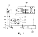
- Fig 1 shows schematically a Pressure regulating system 10 which is in arrangement with a turbo machine for example a nuclear steam turbine 180.
- a main lubricant oil pump 190 supply fluid for example lubricant oil to the nuclear steam turbine 180 passes through a cooler 200 and via filter 210 through a main supply line 310.
- the pressure regulating system 10 is connected to the main supply line 310 through an actuating line 60. Based on requirement of the fluid for example lubricant oil in the nuclear steam turbine 180, excessive fluid can be diverted through the actuating line 60 to the pressure regulating system 10 and from there to oil tank 220 . Further in oil tank 220 an auxiliary lubricant oil pump 230 is provided to supplement the supply of the lubricant oil to the nuclear steam turbine 180.
- An emergency lubricant oil pump 240 has also been provided to supply the lubricant oil to the nuclear steam turbine 180 in case when regular supply is not working
- a preset value of force is fixed in the Pressure regulating system 10.
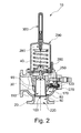
- the first biasing member 40 keeps the moving member 30 at the closed position 100 by applying a first force which is applied through plate 260 onto the head 250 of the moving member 30.
- the actuating line 60 is actuating on the moving member 30 to counter the first bias member 40 by filing a pressurized fluid for example lubricant oil to a preset value into a manifold 170.
- the moving member 30 is lifted to the open position 110 by supplying the pressurized fluid in chambers 90, 270 of the moving member 30 through an impulse line 70.
- the pressurized fluid when filed in the chambers 90, 270 of the moving member 30 creates a second force in the impulse line 70.When the second force in the impulse line 70 is higher than the preset value of the force, keeps the moving member 30 in the open position 110.
- the pressurized fluid when exceeds the preset value of the fluid in the manifold 170 leads to opening of a sealing member 80 to drain the manifold 170 through the opening 50 to the oil tank 220 when the moving member 30 is at the open position 110. Higher is the pressure in the actuating line 60, more flow will be evacuated by the pressure regulating system 10.
- the first biasing member 40 will come down to push the plate 260 onto the head 250 of the moving member 30 to push it towards the closed position 100.
- the moving member 30 start moving from the open position 110 towards the closed position 100 in a normal time period when the pressure in the impulse line 70 is equal to a required lubrication pressure in the nuclear steam turbine.. While closing, the fluid is evacuated.
- the impulse line 70 extends from the Pressure regulating system 10 to the main supply line 310.
- the movement of the Pressure regulating system 10 is slow due to the hydraulic restrictions of the impulse line 70.
- the lubricant oil pumps are large and produce large pressure variations when switched on or switched off.
- a bypass 120 is installed between the moving member 30 and the manifold 170 for a fast evacuation of the fluid in a time period less than the normal time period.
- the bypass 120 allows faster evacuation of the volume of fluid to the manifold 170 if the difference of pressure between the impulse line 70 and the manifold 170 is higher than a pre-set value.
- the bypass120 leads to an early closing of the moving member 30, increase closing tendency of the moving member 30.
- the opening motion of the moving member 30 is unchanged. No fluid is evacuated through impulse line 70.
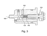
- FIG 3 is a cross section view of the bypass 120 having an inlet opening 160 to receive the fluid form the chamber 90 of the moving member 30.
- a closing member 130 for example a ball is actuated by the flow of the fluid through the inlet opening 160.
- a second biasing member 140 for example a spring counters movement of the closing member 130. The higher pressure of the fluid displace the closing member 130 which in turn moves the second biasing member 140 so that the fluid is drained out from the bypass 120 to the manifold 170 through an outlet opening 150. In absence of fluid supply from the inlet opening 160, the closing member 130 moves back to its original position where it has been kept by the second biasing member 140.
- the bypass 120 does not allow the reverse flow.
- a method for regulating pressure in a turbo machine for example a nuclear steam turbine 180 keeping a moving member 30 for example a piston through a first biasing member 40 at a closed position.
- the moving member 30 is actuated on through an actuating line 60 countering the bias member 40 by filing pressurized fluid into a manifold 170.
- the pressure of the pressurized fluid is permitting to increase to a preset value in the manifold 170, lifting the moving member 30 to an open position110 which leads to opening of the sealing member 80 to drain the manifold 170 through the opening 50.
- An impulse line 70 is supplying the pressurized fluid through in chambers 90, 270 of the moving member 30.
- the moving member 30 is moving from the open position 110 towards the closed position100 in a normal time period when the pressure in the impulse line 70 is more than the manifold 170.
- a bypass 120 is installed between the moving member 30 and the manifold 170 which evacuate the fluid in a time period less than the normal time period. Particularly closing tendency of the moving member 30 is increased through the bypass 120 and the moving member 30 is closed earlier than the normal time period.
- the bypass 120 is receiving the fluid form the chambers 90, 270 of the moving member 30 through an inlet opening 160.
- a closing member 130 in is actuating by the flow of the fluid.
- the movement of the closing member 130 is countered through a second biasing member 140. Further the fluid from the bypass 120 to the manifold 170 is drained through an outlet opening 150.
Landscapes
- Engineering & Computer Science (AREA)
- Mechanical Engineering (AREA)
- General Engineering & Computer Science (AREA)
- Control Of Turbines (AREA)
- Turbine Rotor Nozzle Sealing (AREA)
- Structures Of Non-Positive Displacement Pumps (AREA)
Abstract
Description
- The present disclosure relates to a pressure regulating system for lubricating a turbo machine to and more particularly a system and method for regulating the pressure in a nuclear steam turbine.
- Nuclear steam turbines mostly use centrifugal pumps to supply fluids especially lubricants oil. Apart from the centrifugal pumps, oil lubricant system of the nuclear steam turbines is fed in a normal operation by a pump which delivers a constant flow. During the operation of the nuclear steam turbine as per requirement several pumps are started or stopped or any other anomaly in pressure leading to sudden variation at lubricant oil manifold. These sudden lubricant oil pressure variation leads to the nuclear steam turbines trip. Also the current lubricant systems of the nuclear steam turbines are static and not respond to sudden requirement of the nuclear steam turbines. The tripping of the nuclear steam turbines is not good for the overall plant.
- Consequently, there is need to provide a pressure regulating system which is simple in operation ,easy in installation , less expensive in capital cost and more effective in tackling the sudden variations of the nuclear steam turbines and avoid the tripping of the nuclear steam turbines.
- The present disclosure describes a system and method for regulating the pressure in a turbo machine particularly nuclear steam turbine. This will be presented in the following simplified summary to provide a basic understanding of one or more aspects of the disclosure including all advantages. The sole purpose of this summary is to present some concepts of the disclosure, its aspects and advantages in a simplified form as a prelude to the more detailed description that is presented hereinafter.
- An object of the present disclosure is to propose a system and method for regulating the pressure in a turbo machine particularly nuclear steam turbine which can be used in existing and in new unit installations to significantly reduce the emission of these pollutants.
- The present invention offers a technical solution of controlling variation accurately of pressure at manifold of a pressure regulating system. The solution is to modify pressure regulating system by a dedicated arrangement of bypass which control variations of pressure at the manifold dynamically by responding adequately due to sudden variations of nuclear steam turbines by closing the pressure regulating system in less time than a regular time which leads to restoration of full supply of lubricant oil to the nuclear steam turbine in response of the sudden variations which can be tackled by supplying the adequate amount of the lubricant oil which is required for the working as well as avoiding the tripping of the nuclear steam turbine.
- Various other objects and features of the present disclosure will be apparent from the following detailed description and claims.
- According to one aspect disclosed herein, there is provided a pressure regulating system for a turbo machine comprising a body member having a moving member, an opening and a sealing member. Further a first biasing member for keeping the moving member at a closed position is provided. An actuating line, extended from a main supply line to the pressure regulating system, for actuating on the moving member to counter the bias member by filing pressurized fluid to a preset value into a manifold. An impulse line, extended from the pressure regulating system to the main supply line for supplying the pressurized fluid in at least one chamber of the moving member to lift the moving member to an open position, leads to opening of the sealing member to drain the manifold through the opening.
- In another aspect the moving member moves from the open position towards the closed position in a normal time period when the pressure in the impulse line is equal to a lubrication pressure in the turbo machine.
- In yet another aspect a bypass is installed between the moving member and the manifold for a fast evacuation of the fluid in a time period less than the normal time period.
- In yet another aspect the bypass leads to an early closing of the moving member, increase closing tendency of the moving member.
- In yet another aspect, the bypass comprises an inlet opening to receive the fluid form the chamber of the moving member, an outlet opening to drain the fluid from the bypass to the manifold. A closing member is actuated by the flow of the fluid and a second biasing member to counter movement of the closing member.
- In the pressure regulating system the moving member responds to the pressure requirements, adapting its position as efficiently as possible, to allow the flow of lubricant if the pressure is high in the turbo machine, or close if the pressure is low in the turbo machine.
- The present disclosure also refers to a method for regulating pressure in a turbo machine comprising keeping a moving member through a first biasing member at a closed position, actuating on the moving member through an actuating line, the actuating line extended from a main supply line to the pressure regulating system countering the bias member by filing pressurized fluid into a manifold, permitting the pressure of the pressurized fluid to increase to a preset value in the manifold , supplying the pressurized fluid through an impulse line at least one chamber of the moving member , the impulse line extended from the pressure regulating system to the main supply line, lifting the moving member to an open position which leads to opening of the sealing member to drain the manifold through the opening.
- In another aspect, moving the moving member from the open position towards the closed position in a normal time period when the pressure in the impulse line is equal to a lubrication pressure in the turbo machine.
- In yet another aspect, a bypass is installed between the moving member and the manifold and evacuating the fluid in a time period less than the normal time period.
- In yet another aspect, increasing closing tendency of the moving member and closing the moving member earlier than the normal time period.
- In yet another aspect, receiving the fluid form the chamber of the moving member through an inlet opening in the bypass, actuating at least one closing member in the bypass by the flow of the fluid, countering movement of the closing member in the bypass through at least a second biasing member, draining the fluid from the bypass to the manifold through an outlet opening.
- These together with the other aspects of the present disclosure, along with the various features of novelty that characterize the present disclosure, are pointed out with particularity in the present disclosure. For a better understanding of the present disclosure, its operating advantages, and its uses, reference should be made to the accompanying drawings and descriptive matter in which there are illustrated exemplary embodiments of the present disclosure.
- The advantages and features of the present disclosure will be better understood with reference to the following detailed description and claims taken in conjunction with the accompanying drawings, wherein like elements are identified with like symbols, and in which:
-
FIG.1 is a schematic representation of the an arrangement of pressure regulating system with an nuclear steam turbine in accordance with an exemplary embodiment of the present disclosure; -
FIG.2 is a cross section view of a pressure regulating system in accordance with the present disclosure; -
FIG 3 is a cross section view of a bypass in accordance with the present disclosure; -
Fig 1 . shows schematically a Pressure regulatingsystem 10 which is in arrangement with a turbo machine for example anuclear steam turbine 180. A mainlubricant oil pump 190 supply fluid for example lubricant oil to thenuclear steam turbine 180 passes through acooler 200 and viafilter 210 through amain supply line 310. Thepressure regulating system 10 is connected to themain supply line 310 through an actuatingline 60. Based on requirement of the fluid for example lubricant oil in thenuclear steam turbine 180, excessive fluid can be diverted through the actuatingline 60 to thepressure regulating system 10 and from there tooil tank 220 . Further inoil tank 220 an auxiliarylubricant oil pump 230 is provided to supplement the supply of the lubricant oil to thenuclear steam turbine 180. An emergencylubricant oil pump 240 has also been provided to supply the lubricant oil to thenuclear steam turbine 180 in case when regular supply is not working - As shown in
Fig.2 , thepressure regulating system 10 is having abody member 20 for example a casing. Thebody member 20 having a movingmember 30 for example a piston which operates between a closedposition 100 and anopen position 110. At the closedposition 100 the movingmember 30 rest on an opening 50 which is attached to anoil tank 220. The opening 50 divert the fluid to theoil tank 220 when the movingmember 30 does not rest on the opening 50. The movingmember 30 having itshead 250 pressing againstplate 260 at theopen position 110. Theplate 260 supports afirst biasing member 40 for example a spring. The first biasing member is having a spring compression adjustable by the adjustingscrew 280 andspring top 290. Anut 300 has been provided to avoid leakage along the adjustingscrew 280. A preset value of force is fixed in thePressure regulating system 10. Thefirst biasing member 40 keeps the movingmember 30 at the closedposition 100 by applying a first force which is applied throughplate 260 onto thehead 250 of the movingmember 30. The actuatingline 60 is actuating on the movingmember 30 to counter thefirst bias member 40 by filing a pressurized fluid for example lubricant oil to a preset value into amanifold 170. The movingmember 30 is lifted to theopen position 110 by supplying the pressurized fluid inchambers member 30 through animpulse line 70. The pressurized fluid when filed in thechambers member 30 creates a second force in the impulse line 70.When the second force in theimpulse line 70 is higher than the preset value of the force, keeps the movingmember 30 in theopen position 110. The pressurized fluid when exceeds the preset value of the fluid in themanifold 170 leads to opening of a sealingmember 80 to drain themanifold 170 through the opening 50 to theoil tank 220 when the movingmember 30 is at theopen position 110. Higher is the pressure in the actuatingline 60, more flow will be evacuated by thepressure regulating system 10. - In case when the second force in the
impulse line 70 is less than the preset value of the force which is fixed in thePressure regulating system 10 , thefirst biasing member 40 will come down to push theplate 260 onto thehead 250 of the movingmember 30 to push it towards the closedposition 100. The movingmember 30 start moving from theopen position 110 towards the closedposition 100 in a normal time period when the pressure in theimpulse line 70 is equal to a required lubrication pressure in the nuclear steam turbine.. While closing, the fluid is evacuated. Theimpulse line 70 extends from thePressure regulating system 10 to themain supply line 310. - The movement of the
Pressure regulating system 10 is slow due to the hydraulic restrictions of theimpulse line 70. For nuclear power plant, the lubricant oil pumps are large and produce large pressure variations when switched on or switched off. - In order to increase the closing tendency of the
Pressure regulating system 10, abypass 120 is installed between the movingmember 30 and the manifold 170 for a fast evacuation of the fluid in a time period less than the normal time period. Thebypass 120 allows faster evacuation of the volume of fluid to the manifold 170 if the difference of pressure between theimpulse line 70 and the manifold 170 is higher than a pre-set value. The bypass120 leads to an early closing of the movingmember 30, increase closing tendency of the movingmember 30. On the other hand the opening motion of the movingmember 30 is unchanged. No fluid is evacuated throughimpulse line 70. -
FIG 3 is a cross section view of thebypass 120 having aninlet opening 160 to receive the fluid form thechamber 90 of the movingmember 30. A closingmember 130 for example a ball is actuated by the flow of the fluid through theinlet opening 160. Asecond biasing member 140 for example a spring counters movement of the closingmember 130. The higher pressure of the fluid displace the closingmember 130 which in turn moves thesecond biasing member 140 so that the fluid is drained out from thebypass 120 to the manifold 170 through anoutlet opening 150. In absence of fluid supply from theinlet opening 160, the closingmember 130 moves back to its original position where it has been kept by thesecond biasing member 140. Thebypass 120 does not allow the reverse flow. - In a method for regulating pressure in a turbo machine for example a
nuclear steam turbine 180 keeping a movingmember 30 for example a piston through a first biasingmember 40 at a closed position. The movingmember 30 is actuated on through anactuating line 60 countering thebias member 40 by filing pressurized fluid into amanifold 170. The pressure of the pressurized fluid is permitting to increase to a preset value in the manifold 170, lifting the movingmember 30 to an open position110 which leads to opening of the sealingmember 80 to drain the manifold 170 through theopening 50. Animpulse line 70 is supplying the pressurized fluid through inchambers member 30. The movingmember 30 is moving from theopen position 110 towards the closed position100 in a normal time period when the pressure in theimpulse line 70 is more than the manifold 170. In order to increase the closing tendency of thePressure regulating system 10, abypass 120 is installed between the movingmember 30 and the manifold 170 which evacuate the fluid in a time period less than the normal time period. Particularly closing tendency of the movingmember 30 is increased through thebypass 120 and the movingmember 30 is closed earlier than the normal time period. Thebypass 120 is receiving the fluid form thechambers member 30 through aninlet opening 160. A closingmember 130 in is actuating by the flow of the fluid. The movement of the closingmember 130 is countered through asecond biasing member 140. Further the fluid from thebypass 120 to the manifold 170 is drained through anoutlet opening 150. - The foregoing descriptions of specific embodiments of the present disclosure have been presented for purposes of illustration and description. They are not intended to be exhaustive or to limit the present disclosure to the precise forms disclosed. Many modifications and variations are possible in light of the above examples. The embodiments were chosen and described in order to best explain the principles of the present disclosure and its practical application, to thereby enable others skilled in the art to best utilize the present disclosure and various embodiments with various modifications as are suited to the particular use contemplated. It is understood that various omissions and substitutions of equivalents are contemplated as circumstance may suggest, or render expedient, but such are intended to cover the application or implementation without departing from the spirit or scope of the claims of the present disclosure.
-
- 10
- Pressure regulating system
- 20
- Body member
- 30
- Moving member
- 40
- First bias member
- 50
- Opening
- 60
- Actuating line
- 70
- Impulse line
- 80
- Sealing member
- 90
- First chamber
- 100
- Closed position
- 110
- Open position
- 120
- Bypass
- 130
- Closing member
- 140
- Second biasing member
- 150
- Outlet opening
- 160
- Inlet opening
- 170
- Manifold
- 180
- Nuclear steam turbine
- 190
- Main lubricant oil pump
- 200
- Cooler
- 210
- Filter
- 220
- Oil tank
- 230
- Auxiliary lubricant oil pump
- 240
- Emergency lubricant oil pump
- 250
- Head
- 260
- Plate
- 270
- Chamber
- 280
- Spring adjusting screw
- 290
- Spring top
- 300
- Nut
- 310
- Main supply line
Claims (10)
- A pressure regulating system (10) for a turbo machine comprising
a body member (20) having a moving member (30), an opening (50) and a sealing member (80),
a first biasing member (40) to keep the moving member (30) at a closed position (100),
an actuating line (60), extended from a main supply line (310) to the pressure regulating system (10), for actuating on the moving member (30) to counter the bias member (40) by filing pressurized fluid into a manifold (170) permitting the pressure of the pressurized fluid to increase to a preset value in the manifold (170),
an impulse line (70), extended from the pressure regulating system (10) to the main supply line (360) for supplying the pressurized fluid in at least one chamber (90) of the moving member (30) to lift the moving member (30) to an open position(110), leads to opening of the sealing member(80) to drain the manifold(170) through the opening (50). - The pressure regulating system (10) of claim 1, wherein the moving member (30) moves from the open position (110) towards the closed position (100) in a normal time period when the pressure in the impulse line (70) is equal to a lubrication pressure in the turbo machine.
- The pressure regulating system (10) of claim 1, wherein a bypass(120) is installed between the moving member (30) and the manifold (170) for a fast evacuation of the fluid in a time period less than the normal time period.
- The pressure regulating system (10) of claim 3, wherein the bypass(120) leads to an early closing of the moving member (30), increase closing tendency of the moving member (30).
- The pressure regulating system (10) of claim 3, wherein the bypass (120) comprises
an inlet opening (160) to receive the fluid form the chamber (90) of the moving member (30),
at least one closing member (130) actuated by the flow of the fluid,
at least a second biasing member (140) to counter movement of the closing member (130) and
an outlet opening (150) to drain the fluid from the bypass (120) to the manifold (170) - A method for regulating pressure in a turbo machine comprising
keeping a moving member (30) through a first biasing member (40) at a closed position,
actuating on the moving member (30) through an actuating line (60), the actuating line (60) extended from a main supply line(310) to the pressure regulating system (10),
countering the bias member (40) by filing pressurized fluid into a manifold (170), permitting the pressure of the pressurized fluid to increase to a preset value in the manifold (170),
supplying the pressurized fluid through an impulse line (70) in at least one chamber (90) of the moving member (30), the impulse line extended from the pressure regulating system (10) to the main supply line(310),
lifting the moving member (30) to an open position(110) which leads to opening of the sealing member(80) to drain the manifold(170) through the opening (50). - The method of claim 6, wherein, moving the moving member (30) from the open position (110) towards the closed position(100) in a normal time period when the pressure in the impulse line (70) is equal to a lubrication pressure in the turbo machine.
- The method of claim 6, wherein, installing a bypass (120) between the moving member (30) and the manifold (170), evacuating the fluid in a time period less than the normal time period.
- The method of claim 8, wherein the bypass (120),
increasing closing tendency of the moving member (30) through the bypass (120), closing the moving member (30) earlier than the normal time period. - The method of claim 8, wherein the bypass (120),
receiving the fluid form the chamber (90) of the moving member (30) through an inlet opening (160),
actuating at least one closing member (130) by the flow of the fluid, countering movement of the closing member (130) through at least a second biasing member (140).
draining the fluid from the bypass (120) to the manifold (170) through an outlet opening (150).
Priority Applications (4)
| Application Number | Priority Date | Filing Date | Title |
|---|---|---|---|
| EP15290115.3A EP3088687B1 (en) | 2015-04-29 | 2015-04-29 | A system and method for regulating pressure for a turbomachine |
| US15/138,553 US9976445B2 (en) | 2015-04-29 | 2016-04-26 | System and method for regulating pressure for a turbomachine |
| RU2016116276A RU2684695C2 (en) | 2015-04-29 | 2016-04-26 | System and method for regulating pressure for a turbomachine |
| CN201610276123.7A CN106089333B (en) | 2015-04-29 | 2016-04-29 | System and method for regulating pressure of a turbomachine |
Applications Claiming Priority (1)
| Application Number | Priority Date | Filing Date | Title |
|---|---|---|---|
| EP15290115.3A EP3088687B1 (en) | 2015-04-29 | 2015-04-29 | A system and method for regulating pressure for a turbomachine |
Publications (2)
| Publication Number | Publication Date |
|---|---|
| EP3088687A1 true EP3088687A1 (en) | 2016-11-02 |
| EP3088687B1 EP3088687B1 (en) | 2021-01-27 |
Family
ID=53180670
Family Applications (1)
| Application Number | Title | Priority Date | Filing Date |
|---|---|---|---|
| EP15290115.3A Active EP3088687B1 (en) | 2015-04-29 | 2015-04-29 | A system and method for regulating pressure for a turbomachine |
Country Status (4)
| Country | Link |
|---|---|
| US (1) | US9976445B2 (en) |
| EP (1) | EP3088687B1 (en) |
| CN (1) | CN106089333B (en) |
| RU (1) | RU2684695C2 (en) |
Families Citing this family (1)
| Publication number | Priority date | Publication date | Assignee | Title |
|---|---|---|---|---|
| CN110566286A (en) * | 2019-10-24 | 2019-12-13 | 陕西正本环境工程有限公司 | Novel flue gas turbine power generation device |
Citations (3)
| Publication number | Priority date | Publication date | Assignee | Title |
|---|---|---|---|---|
| US2298646A (en) * | 1940-10-08 | 1942-10-13 | Wright Aeronautical Corp | Lubrication system |
| FR2292858A1 (en) * | 1974-11-29 | 1976-06-25 | Kloeckner Humboldt Deutz Ag | IC engine oil press control/relief valves - design combining both and permitting smaller coolers and filters |
| DE102004049029A1 (en) * | 2004-10-08 | 2006-04-20 | Audi Ag | Device for regulating lubricating oil pressure includes control valve mechanism where different active faces of one or more work pistons are impinged dependent on pressure level to be set |
Family Cites Families (4)
| Publication number | Priority date | Publication date | Assignee | Title |
|---|---|---|---|---|
| DE59203461D1 (en) * | 1991-11-04 | 1995-10-05 | Asea Brown Boveri | Supply circuit for a two-pipe hydraulic system. |
| ATA175997A (en) * | 1997-10-16 | 2002-02-15 | Tcg Unitech Ag | PRESSURE CONTROL VALVE |
| DE102010019044B4 (en) * | 2010-05-03 | 2014-09-04 | Geräte- und Pumpenbau GmbH Dr. Eugen Schmidt | Lubricant valve for oil pumps of internal combustion engines |
| CN202402087U (en) * | 2011-11-09 | 2012-08-29 | 中国神华能源股份有限公司 | Jacking system of steam turbine rotor |
-
2015
- 2015-04-29 EP EP15290115.3A patent/EP3088687B1/en active Active
-
2016
- 2016-04-26 US US15/138,553 patent/US9976445B2/en active Active
- 2016-04-26 RU RU2016116276A patent/RU2684695C2/en active
- 2016-04-29 CN CN201610276123.7A patent/CN106089333B/en active Active
Patent Citations (3)
| Publication number | Priority date | Publication date | Assignee | Title |
|---|---|---|---|---|
| US2298646A (en) * | 1940-10-08 | 1942-10-13 | Wright Aeronautical Corp | Lubrication system |
| FR2292858A1 (en) * | 1974-11-29 | 1976-06-25 | Kloeckner Humboldt Deutz Ag | IC engine oil press control/relief valves - design combining both and permitting smaller coolers and filters |
| DE102004049029A1 (en) * | 2004-10-08 | 2006-04-20 | Audi Ag | Device for regulating lubricating oil pressure includes control valve mechanism where different active faces of one or more work pistons are impinged dependent on pressure level to be set |
Also Published As
| Publication number | Publication date |
|---|---|
| CN106089333A (en) | 2016-11-09 |
| RU2684695C2 (en) | 2019-04-11 |
| EP3088687B1 (en) | 2021-01-27 |
| RU2016116276A3 (en) | 2019-02-01 |
| RU2016116276A (en) | 2017-11-01 |
| US20160319700A1 (en) | 2016-11-03 |
| CN106089333B (en) | 2020-08-11 |
| US9976445B2 (en) | 2018-05-22 |
Similar Documents
| Publication | Publication Date | Title |
|---|---|---|
| EP1979616B1 (en) | Variable displacement variable pressure vane pump system | |
| KR100644295B1 (en) | A drive unit with a retarder | |
| US10378672B2 (en) | Method of controlling a valve and valve | |
| CN206320089U (en) | Hydraulic control system based on electro-hydraulic servo type hydraulic press | |
| EP2050970A3 (en) | Hydraulic circuit for heavy equipment | |
| CN201865889U (en) | Clearance stepless adjustment actuator of reciprocating compressor | |
| CN107109961B (en) | Actuating drive for a control valve, in particular a steam turbine control valve, and method for operating the actuating drive | |
| US20220333617A1 (en) | Electro-hydrostatic actuation system | |
| US9976445B2 (en) | System and method for regulating pressure for a turbomachine | |
| CN104197080A (en) | Hydraulic control system for quick opening and closing of valve | |
| CN117703708A (en) | Hydraulic drive for a hydraulic load which is pressurized alternately in opposite directions during operation | |
| EP3875781B1 (en) | Hydraulic unit with combined pneumatic/servomotor action and related use | |
| US9920778B2 (en) | Valve for the temperature-dependent control of at least one hydraulic load | |
| KR20180029078A (en) | Solenoid operated pressure relief valve | |
| EP3009619B1 (en) | Gas exchange valve actuator for axial displacement of a gas exchange valve of a combustion engine | |
| CN204900413U (en) | Hydraulic cylinder durability test system | |
| CN107002716A (en) | Actuating drive for a control valve, in particular a steam turbine control valve, and method for operating the same | |
| CN101016901A (en) | Screw bolt compressor suitable for parallel system and having low loading start up function | |
| CN204459724U (en) | Pressure controlled omnidistance displacement-variable oil pump | |
| SE536251C2 (en) | Procedure and device for valve control | |
| US2955743A (en) | Method and apparatus for preventing surging in fans, blowers, and turbocompressors | |
| JP2021032223A (en) | Control device and abnormality detection method | |
| CN214367021U (en) | Hydraulic energy station with compressor load stepping control function | |
| KR102525617B1 (en) | Thrust control apparatus for balance piston of nuclear power plant | |
| AU2018256615A1 (en) | Lubricating-grease pump and method for recovery of leakage grease of a lubricating-grease pump |
Legal Events
| Date | Code | Title | Description |
|---|---|---|---|
| PUAI | Public reference made under article 153(3) epc to a published international application that has entered the european phase |
Free format text: ORIGINAL CODE: 0009012 |
|
| AK | Designated contracting states |
Kind code of ref document: A1 Designated state(s): AL AT BE BG CH CY CZ DE DK EE ES FI FR GB GR HR HU IE IS IT LI LT LU LV MC MK MT NL NO PL PT RO RS SE SI SK SM TR |
|
| AX | Request for extension of the european patent |
Extension state: BA ME |
|
| 17P | Request for examination filed |
Effective date: 20170502 |
|
| RBV | Designated contracting states (corrected) |
Designated state(s): AL AT BE BG CH CY CZ DE DK EE ES FI FR GB GR HR HU IE IS IT LI LT LU LV MC MK MT NL NO PL PT RO RS SE SI SK SM TR |
|
| STAA | Information on the status of an ep patent application or granted ep patent |
Free format text: STATUS: REQUEST FOR EXAMINATION WAS MADE |
|
| REG | Reference to a national code |
Ref country code: DE Ref legal event code: R079 Ref document number: 602015065186 Country of ref document: DE Free format text: PREVIOUS MAIN CLASS: F01D0025200000 Ipc: F01M0001160000 |
|
| STAA | Information on the status of an ep patent application or granted ep patent |
Free format text: STATUS: EXAMINATION IS IN PROGRESS |
|
| RIC1 | Information provided on ipc code assigned before grant |
Ipc: F01D 25/20 20060101ALI20190412BHEP Ipc: F01M 1/16 20060101AFI20190412BHEP Ipc: F01D 25/18 20060101ALI20190412BHEP |
|
| 17Q | First examination report despatched |
Effective date: 20190517 |
|
| GRAP | Despatch of communication of intention to grant a patent |
Free format text: ORIGINAL CODE: EPIDOSNIGR1 |
|
| STAA | Information on the status of an ep patent application or granted ep patent |
Free format text: STATUS: GRANT OF PATENT IS INTENDED |
|
| INTG | Intention to grant announced |
Effective date: 20200914 |
|
| GRAS | Grant fee paid |
Free format text: ORIGINAL CODE: EPIDOSNIGR3 |
|
| GRAA | (expected) grant |
Free format text: ORIGINAL CODE: 0009210 |
|
| STAA | Information on the status of an ep patent application or granted ep patent |
Free format text: STATUS: THE PATENT HAS BEEN GRANTED |
|
| AK | Designated contracting states |
Kind code of ref document: B1 Designated state(s): AL AT BE BG CH CY CZ DE DK EE ES FI FR GB GR HR HU IE IS IT LI LT LU LV MC MK MT NL NO PL PT RO RS SE SI SK SM TR |
|
| REG | Reference to a national code |
Ref country code: GB Ref legal event code: FG4D |
|
| REG | Reference to a national code |
Ref country code: CH Ref legal event code: EP |
|
| REG | Reference to a national code |
Ref country code: AT Ref legal event code: REF Ref document number: 1358537 Country of ref document: AT Kind code of ref document: T Effective date: 20210215 |
|
| REG | Reference to a national code |
Ref country code: IE Ref legal event code: FG4D |
|
| REG | Reference to a national code |
Ref country code: DE Ref legal event code: R096 Ref document number: 602015065186 Country of ref document: DE |
|
| RAP4 | Party data changed (patent owner data changed or rights of a patent transferred) |
Owner name: GENERAL ELECTRIC TECHNOLOGY GMBH |
|
| REG | Reference to a national code |
Ref country code: NL Ref legal event code: MP Effective date: 20210127 |
|
| REG | Reference to a national code |
Ref country code: LT Ref legal event code: MG9D |
|
| REG | Reference to a national code |
Ref country code: AT Ref legal event code: MK05 Ref document number: 1358537 Country of ref document: AT Kind code of ref document: T Effective date: 20210127 |
|
| PG25 | Lapsed in a contracting state [announced via postgrant information from national office to epo] |
Ref country code: LT Free format text: LAPSE BECAUSE OF FAILURE TO SUBMIT A TRANSLATION OF THE DESCRIPTION OR TO PAY THE FEE WITHIN THE PRESCRIBED TIME-LIMIT Effective date: 20210127 Ref country code: PT Free format text: LAPSE BECAUSE OF FAILURE TO SUBMIT A TRANSLATION OF THE DESCRIPTION OR TO PAY THE FEE WITHIN THE PRESCRIBED TIME-LIMIT Effective date: 20210527 Ref country code: NO Free format text: LAPSE BECAUSE OF FAILURE TO SUBMIT A TRANSLATION OF THE DESCRIPTION OR TO PAY THE FEE WITHIN THE PRESCRIBED TIME-LIMIT Effective date: 20210427 Ref country code: NL Free format text: LAPSE BECAUSE OF FAILURE TO SUBMIT A TRANSLATION OF THE DESCRIPTION OR TO PAY THE FEE WITHIN THE PRESCRIBED TIME-LIMIT Effective date: 20210127 Ref country code: BG Free format text: LAPSE BECAUSE OF FAILURE TO SUBMIT A TRANSLATION OF THE DESCRIPTION OR TO PAY THE FEE WITHIN THE PRESCRIBED TIME-LIMIT Effective date: 20210427 Ref country code: FI Free format text: LAPSE BECAUSE OF FAILURE TO SUBMIT A TRANSLATION OF THE DESCRIPTION OR TO PAY THE FEE WITHIN THE PRESCRIBED TIME-LIMIT Effective date: 20210127 Ref country code: GR Free format text: LAPSE BECAUSE OF FAILURE TO SUBMIT A TRANSLATION OF THE DESCRIPTION OR TO PAY THE FEE WITHIN THE PRESCRIBED TIME-LIMIT Effective date: 20210428 Ref country code: HR Free format text: LAPSE BECAUSE OF FAILURE TO SUBMIT A TRANSLATION OF THE DESCRIPTION OR TO PAY THE FEE WITHIN THE PRESCRIBED TIME-LIMIT Effective date: 20210127 |
|
| PG25 | Lapsed in a contracting state [announced via postgrant information from national office to epo] |
Ref country code: PL Free format text: LAPSE BECAUSE OF FAILURE TO SUBMIT A TRANSLATION OF THE DESCRIPTION OR TO PAY THE FEE WITHIN THE PRESCRIBED TIME-LIMIT Effective date: 20210127 Ref country code: LV Free format text: LAPSE BECAUSE OF FAILURE TO SUBMIT A TRANSLATION OF THE DESCRIPTION OR TO PAY THE FEE WITHIN THE PRESCRIBED TIME-LIMIT Effective date: 20210127 Ref country code: RS Free format text: LAPSE BECAUSE OF FAILURE TO SUBMIT A TRANSLATION OF THE DESCRIPTION OR TO PAY THE FEE WITHIN THE PRESCRIBED TIME-LIMIT Effective date: 20210127 Ref country code: AT Free format text: LAPSE BECAUSE OF FAILURE TO SUBMIT A TRANSLATION OF THE DESCRIPTION OR TO PAY THE FEE WITHIN THE PRESCRIBED TIME-LIMIT Effective date: 20210127 Ref country code: SE Free format text: LAPSE BECAUSE OF FAILURE TO SUBMIT A TRANSLATION OF THE DESCRIPTION OR TO PAY THE FEE WITHIN THE PRESCRIBED TIME-LIMIT Effective date: 20210127 |
|
| PG25 | Lapsed in a contracting state [announced via postgrant information from national office to epo] |
Ref country code: IS Free format text: LAPSE BECAUSE OF FAILURE TO SUBMIT A TRANSLATION OF THE DESCRIPTION OR TO PAY THE FEE WITHIN THE PRESCRIBED TIME-LIMIT Effective date: 20210527 |
|
| REG | Reference to a national code |
Ref country code: DE Ref legal event code: R097 Ref document number: 602015065186 Country of ref document: DE |
|
| PG25 | Lapsed in a contracting state [announced via postgrant information from national office to epo] |
Ref country code: EE Free format text: LAPSE BECAUSE OF FAILURE TO SUBMIT A TRANSLATION OF THE DESCRIPTION OR TO PAY THE FEE WITHIN THE PRESCRIBED TIME-LIMIT Effective date: 20210127 Ref country code: CZ Free format text: LAPSE BECAUSE OF FAILURE TO SUBMIT A TRANSLATION OF THE DESCRIPTION OR TO PAY THE FEE WITHIN THE PRESCRIBED TIME-LIMIT Effective date: 20210127 Ref country code: SM Free format text: LAPSE BECAUSE OF FAILURE TO SUBMIT A TRANSLATION OF THE DESCRIPTION OR TO PAY THE FEE WITHIN THE PRESCRIBED TIME-LIMIT Effective date: 20210127 |
|
| PG25 | Lapsed in a contracting state [announced via postgrant information from national office to epo] |
Ref country code: MC Free format text: LAPSE BECAUSE OF FAILURE TO SUBMIT A TRANSLATION OF THE DESCRIPTION OR TO PAY THE FEE WITHIN THE PRESCRIBED TIME-LIMIT Effective date: 20210127 Ref country code: DK Free format text: LAPSE BECAUSE OF FAILURE TO SUBMIT A TRANSLATION OF THE DESCRIPTION OR TO PAY THE FEE WITHIN THE PRESCRIBED TIME-LIMIT Effective date: 20210127 Ref country code: ES Free format text: LAPSE BECAUSE OF FAILURE TO SUBMIT A TRANSLATION OF THE DESCRIPTION OR TO PAY THE FEE WITHIN THE PRESCRIBED TIME-LIMIT Effective date: 20210127 Ref country code: SK Free format text: LAPSE BECAUSE OF FAILURE TO SUBMIT A TRANSLATION OF THE DESCRIPTION OR TO PAY THE FEE WITHIN THE PRESCRIBED TIME-LIMIT Effective date: 20210127 Ref country code: RO Free format text: LAPSE BECAUSE OF FAILURE TO SUBMIT A TRANSLATION OF THE DESCRIPTION OR TO PAY THE FEE WITHIN THE PRESCRIBED TIME-LIMIT Effective date: 20210127 |
|
| PLBE | No opposition filed within time limit |
Free format text: ORIGINAL CODE: 0009261 |
|
| STAA | Information on the status of an ep patent application or granted ep patent |
Free format text: STATUS: NO OPPOSITION FILED WITHIN TIME LIMIT |
|
| GBPC | Gb: european patent ceased through non-payment of renewal fee |
Effective date: 20210429 |
|
| PG25 | Lapsed in a contracting state [announced via postgrant information from national office to epo] |
Ref country code: LU Free format text: LAPSE BECAUSE OF NON-PAYMENT OF DUE FEES Effective date: 20210429 |
|
| 26N | No opposition filed |
Effective date: 20211028 |
|
| REG | Reference to a national code |
Ref country code: BE Ref legal event code: MM Effective date: 20210430 |
|
| PG25 | Lapsed in a contracting state [announced via postgrant information from national office to epo] |
Ref country code: GB Free format text: LAPSE BECAUSE OF NON-PAYMENT OF DUE FEES Effective date: 20210429 Ref country code: LI Free format text: LAPSE BECAUSE OF NON-PAYMENT OF DUE FEES Effective date: 20210430 Ref country code: CH Free format text: LAPSE BECAUSE OF NON-PAYMENT OF DUE FEES Effective date: 20210430 Ref country code: AL Free format text: LAPSE BECAUSE OF FAILURE TO SUBMIT A TRANSLATION OF THE DESCRIPTION OR TO PAY THE FEE WITHIN THE PRESCRIBED TIME-LIMIT Effective date: 20210127 |
|
| PG25 | Lapsed in a contracting state [announced via postgrant information from national office to epo] |
Ref country code: SI Free format text: LAPSE BECAUSE OF FAILURE TO SUBMIT A TRANSLATION OF THE DESCRIPTION OR TO PAY THE FEE WITHIN THE PRESCRIBED TIME-LIMIT Effective date: 20210127 |
|
| PG25 | Lapsed in a contracting state [announced via postgrant information from national office to epo] |
Ref country code: IT Free format text: LAPSE BECAUSE OF FAILURE TO SUBMIT A TRANSLATION OF THE DESCRIPTION OR TO PAY THE FEE WITHIN THE PRESCRIBED TIME-LIMIT Effective date: 20210127 Ref country code: IE Free format text: LAPSE BECAUSE OF NON-PAYMENT OF DUE FEES Effective date: 20210429 |
|
| PG25 | Lapsed in a contracting state [announced via postgrant information from national office to epo] |
Ref country code: IS Free format text: LAPSE BECAUSE OF FAILURE TO SUBMIT A TRANSLATION OF THE DESCRIPTION OR TO PAY THE FEE WITHIN THE PRESCRIBED TIME-LIMIT Effective date: 20210527 |
|
| PG25 | Lapsed in a contracting state [announced via postgrant information from national office to epo] |
Ref country code: BE Free format text: LAPSE BECAUSE OF NON-PAYMENT OF DUE FEES Effective date: 20210430 |
|
| PG25 | Lapsed in a contracting state [announced via postgrant information from national office to epo] |
Ref country code: HU Free format text: LAPSE BECAUSE OF FAILURE TO SUBMIT A TRANSLATION OF THE DESCRIPTION OR TO PAY THE FEE WITHIN THE PRESCRIBED TIME-LIMIT; INVALID AB INITIO Effective date: 20150429 |
|
| P01 | Opt-out of the competence of the unified patent court (upc) registered |
Effective date: 20230523 |
|
| PG25 | Lapsed in a contracting state [announced via postgrant information from national office to epo] |
Ref country code: CY Free format text: LAPSE BECAUSE OF FAILURE TO SUBMIT A TRANSLATION OF THE DESCRIPTION OR TO PAY THE FEE WITHIN THE PRESCRIBED TIME-LIMIT Effective date: 20210127 |
|
| PG25 | Lapsed in a contracting state [announced via postgrant information from national office to epo] |
Ref country code: MK Free format text: LAPSE BECAUSE OF FAILURE TO SUBMIT A TRANSLATION OF THE DESCRIPTION OR TO PAY THE FEE WITHIN THE PRESCRIBED TIME-LIMIT Effective date: 20210127 |
|
| PG25 | Lapsed in a contracting state [announced via postgrant information from national office to epo] |
Ref country code: MT Free format text: LAPSE BECAUSE OF FAILURE TO SUBMIT A TRANSLATION OF THE DESCRIPTION OR TO PAY THE FEE WITHIN THE PRESCRIBED TIME-LIMIT Effective date: 20210127 |
|
| REG | Reference to a national code |
Ref country code: DE Ref legal event code: R081 Ref document number: 602015065186 Country of ref document: DE Owner name: ARABELLE SOLUTIONS FRANCE, FR Free format text: FORMER OWNER: GENERAL ELECTRIC TECHNOLOGY GMBH, BADEN, CH Ref country code: DE Ref legal event code: R081 Ref document number: 602015065186 Country of ref document: DE Owner name: ARABELLE TECHNOLOGIES, FR Free format text: FORMER OWNER: GENERAL ELECTRIC TECHNOLOGY GMBH, BADEN, CH |
|
| REG | Reference to a national code |
Ref country code: DE Ref legal event code: R081 Ref document number: 602015065186 Country of ref document: DE Owner name: ARABELLE SOLUTIONS FRANCE, FR Free format text: FORMER OWNER: ARABELLE TECHNOLOGIES, BOULOGNE-BILLANCOURT, FR |
|
| PGFP | Annual fee paid to national office [announced via postgrant information from national office to epo] |
Ref country code: DE Payment date: 20250319 Year of fee payment: 11 |
|
| PG25 | Lapsed in a contracting state [announced via postgrant information from national office to epo] |
Ref country code: TR Free format text: LAPSE BECAUSE OF FAILURE TO SUBMIT A TRANSLATION OF THE DESCRIPTION OR TO PAY THE FEE WITHIN THE PRESCRIBED TIME-LIMIT Effective date: 20210127 |
|
| PGFP | Annual fee paid to national office [announced via postgrant information from national office to epo] |
Ref country code: FR Payment date: 20260319 Year of fee payment: 12 |