EP3088634A1 - Pregrouted pc steel and method for hardening pregrouted layer - Google Patents
Pregrouted pc steel and method for hardening pregrouted layer Download PDFInfo
- Publication number
- EP3088634A1 EP3088634A1 EP14875354.4A EP14875354A EP3088634A1 EP 3088634 A1 EP3088634 A1 EP 3088634A1 EP 14875354 A EP14875354 A EP 14875354A EP 3088634 A1 EP3088634 A1 EP 3088634A1
- Authority
- EP
- European Patent Office
- Prior art keywords
- pregrouted
- layer
- strand
- resin
- filling resin
- Prior art date
- Legal status (The legal status is an assumption and is not a legal conclusion. Google has not performed a legal analysis and makes no representation as to the accuracy of the status listed.)
- Granted
Links
Images

Classifications
-
- E—FIXED CONSTRUCTIONS
- E04—BUILDING
- E04C—STRUCTURAL ELEMENTS; BUILDING MATERIALS
- E04C5/00—Reinforcing elements, e.g. for concrete; Auxiliary elements therefor
- E04C5/08—Members specially adapted to be used in prestressed constructions
-
- E—FIXED CONSTRUCTIONS
- E04—BUILDING
- E04C—STRUCTURAL ELEMENTS; BUILDING MATERIALS
- E04C5/00—Reinforcing elements, e.g. for concrete; Auxiliary elements therefor
- E04C5/08—Members specially adapted to be used in prestressed constructions
- E04C5/085—Tensile members made of fiber reinforced plastics
-
- E—FIXED CONSTRUCTIONS
- E04—BUILDING
- E04C—STRUCTURAL ELEMENTS; BUILDING MATERIALS
- E04C5/00—Reinforcing elements, e.g. for concrete; Auxiliary elements therefor
- E04C5/01—Reinforcing elements of metal, e.g. with non-structural coatings
-
- E—FIXED CONSTRUCTIONS
- E04—BUILDING
- E04C—STRUCTURAL ELEMENTS; BUILDING MATERIALS
- E04C5/00—Reinforcing elements, e.g. for concrete; Auxiliary elements therefor
- E04C5/08—Members specially adapted to be used in prestressed constructions
- E04C5/10—Ducts
-
- E—FIXED CONSTRUCTIONS
- E04—BUILDING
- E04G—SCAFFOLDING; FORMS; SHUTTERING; BUILDING IMPLEMENTS OR AIDS, OR THEIR USE; HANDLING BUILDING MATERIALS ON THE SITE; REPAIRING, BREAKING-UP OR OTHER WORK ON EXISTING BUILDINGS
- E04G21/00—Preparing, conveying, or working-up building materials or building elements in situ; Other devices or measures for constructional work
- E04G21/12—Mounting of reinforcing inserts; Prestressing
Definitions
- the present invention relates to a pregrouted PC (prestressed concrete) steel material for use in a PC construction method such as a PC post tensioning method, and a curing method for a pregrouted layer in the pregrouted PC steel material.
- a PC construction method such as a PC post tensioning method
- a curing method for a pregrouted layer in the pregrouted PC steel material.
- a typical post tensioning method tensions and fixes a PC steel material by inserting the PC steel material in a cylindrical sheath buried in concrete beforehand, and applies compressive stress to the concrete by the reaction force of tensioning force.
- This method covers the disadvantage such that the tensile strength of the concrete is low.
- a grout material such as cement milk, is injected and mixed between the sheath and the PC steel material to prevent adhesion between the PC steel material and the concrete and corrosion of the PC steel material.
- This pregrouted PC steel material includes a PC strand formed by twisting a plurality of steel wires (element wires) together, a pregrouted layer disposed on an outer periphery of the PC strand to contain the PC strand, and a sheath that covers an outer periphery of the pregrouted layer (see paragraph 0005 and Fig. 2 of PTL 1).
- the pregrouted material (pregrouted layer) is required to have a long tensionable period in which the PC grout material does not cure until the PC strand is tensioned, and needs to cure at ordinary temperature after the PC strand is fixed by the application of tensioning force (after concrete is compressed).
- the curing agent is mixed beforehand, or compounding or the like of the grout material is devised.
- the curing degree changes according to the environment such as temperature, and the construction period often deviates from the planned period.
- the construction period is extended, curing of the grout material proceeds, and this may hinder the operation of tensioning the PC steel material.
- heating elements are provided in a sheath (PTL 4).
- PTL 4 a sheath
- capsules containing a curing agent are mixed in a pregrouted layer (PTL 5, Abstract).
- PTL 5, Abstract a pregrouted layer
- the capsules are broken via the pregrouted layer by tensioning force of a PC steel material so that the curing agent flows into the pregrouted layer.
- the capsules may not be broken smoothly. That is, the curing time of the pregrouted layer is unstable.
- paragraph 0022 of PTL 1 also describes the idea of mixing, in a pregrouted layer, microcapsules in each of which a curing agent is wrapped with a coating film, these capsules are broken by dissolution of the coating film due to water or the like in the pregrouted layer or heat application so that the curing agent therein flows into the pregrouted layer.
- an object of the present invention is to allow a pregrouted layer to be cured by means other than the above-described heating means from an initial period where promotion of curing is demanded.
- a pregrouted PC steel material includes a PC strand formed by twisting a plurality of steel wires, a pregrouted layer disposed on an outer periphery of the PC strand to contain the PC strand, and a sheath configured to cover an outer periphery of the pregrouted layer.
- a filling resin configured to promote curing of the pregrouted layer is filled between the steel wires in the PC strand. The filling resin does not exude to the pregrouted layer before tensioning of the PC strand, and exudes to the pregrouted layer owing to a tensioning force during the tensioning.
- the filling resin starts flowing out to the pregrouted layer and curing proceeds from an initial period in which promotion of curing of the pregrouted layer is demanded and in which compressive stress is applied to concrete by tensioning the PC strand.
- the construction period can be shortened without hindering the operation of tensioning the PC strand.
- a pregrouted PC steel material includes a PC strand formed by twisting a plurality of steel wires, a pregrouted layer disposed on an outer periphery of the PC strand to contain the PC strand, and a sheath that covers an outer periphery of the pregrouted layer.
- the pregrouted PC steel material adopts a structure in which a filling resin for promoting curing of the pregrouted layer (hereinafter referred to as a filling resin) is filled between the steel wires in the PC strand and the filling resin does not exude to the pregrouted layer before tensioning of the PC strand and exudes to the pregrouted layer owing to tensioning force during the tensioning.
- an initial period in which promotion of curing of the pregrouted layer is demanded is the time when, after concrete is cast, it is subjected to prestressing, that is, a PC steel material is tensioned and fixed and compressive stress is applied to the concrete by reaction force of the tensioning force. For this reason, first, curing of the pregrouted layer is promoted when the compressive stress is applied to the concrete by the tensioning force.
- a filling resin for promoting curing of the pregrouted layer is filled between the steel wires in the PC strand during prestressing in order to promote curing of the pregrouted layer.
- the filling resin between the steel wires in the PC strand does not exude until the PC strand is tensioned (before tensioning and fixing start), and the filling resin exudes to cure the pregrouted layer only after the gap between the steel wires is reduced during tensioning.
- the filling resin does not flow out to the pregrouted layer until the PC strand is tensioned, and this does not hinder the operation of tensioning the PC strand by curing of the pregrouted layer.
- the gap between the steel wires is certainly reduced.
- the filling resin flows out (exudes) to the pregrouted layer and cures the pregrouted layer only after the reduction. That is, the initial period when curing of the pregrouted layer promoted is the time of prestressing when the PC strand is tensioned to apply compressive stress to the concrete after the concrete is cast.
- epoxy resin As the pregrouted layer, well-known resins conventionally used, for example, epoxy resin or a resin mainly composed of epoxy resin can be adopted.
- the filling resin exudes from between the steel wires in the PC strand into the grout resin layer (pregrouted layer) owing to reduction of the gap between the steel wires during the tensioning operation, and thereby promotes curing of the grout resin layer.
- the pregrouted layer is formed of epoxy resin or a resin mainly composed of epoxy resin, for example, a curing agent for epoxy resin is conceivable as the filling resin.
- the filling resin may be powder or beads obtained by granulating the powder, it may be microcapsules wrapped with coating films that are dissolved by moisture absorption or broken by tensioning force of the PC strand (filled with filling resin).
- a binder resin can be appropriately mixed therein. While the kind of binder resin is not particularly limited, epoxy resin that can finally cure together with the grout resin is preferably used.
- an amine-based compound, an anhydride-based compound, an amide-based compound, a phenol-based compound, and a carboxylic compound are given as examples. These curing agents may be used alone, or two or more of these may be used. While the kind of curing agent is not particularly limited, a ketimine is suitable from the viewpoint of the tensionable period of the steel material.
- epoxy resin used in the binder resin a novolac epoxy resin, a bisphenol A epoxy resin, a biphenyl epoxy resin, a triphenylmethane epoxy resin, and a phenolic aralkyl epoxy resin are given as examples. These epoxy resins may be used alone, or two or more of these may be used. While the kind of epoxy resin is not particularly limited, a bisphenol A epoxy resin is suitable because of its viscosity and ease of treatment.
- the optimal compounding amount of epoxy resin curing agent differs according to the combination thereof.
- the compounding amount of ketimine is 2.5 to 30 phr, preferably 3.5 to 20 phr, and more preferably 4.5 to 15 phr.
- the curing speed may be insufficient when the compounding amount of ketimine is too small, and the tensionable period of the steel material may be insufficient when the compounding amount of ketimine is too large.
- An organic filler can be added to the filling resin as necessary. This addition of the filler can improve a thickening property, a thixotropic property, and a drip preventive property of the filling resin.
- the organic filler powders of crystalline silica, fused silica, alumina, zircon, calcium silicate, calcium carbonate, calcium oxide, silicon carbide, silicon nitride, boron nitride, zirconia, forsterite, steatite, spinel, titania, and talc or beads formed by spheroidizing these powders are given as examples, but the organic filler is not limited thereto. These fillers may be used alone, or two or more of these may be used.
- the content of the organic filler is such as to occupy 0 to 95 wt% of the curable resin composite of the present invention.
- a silane coupling agent such as stearin acid, palmitic acid, zinc stearate, and calcium stearate
- various compounding agents such as pigment, and various thermoplastic resins can be added.
- prestressing of concrete by this pregrouted PC steel material is performed by burying the pregrouted steel material in the concrete beforehand, casting the concrete, and then tensioning a PC strand.
- the gap between the steel wires in the PC strand is reduced by the tensioning force.
- the filling resin filled in the gap is caused to exude into the pregrouted layer and cure the pregrouted layer.
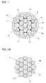
- a pregrouted PC steel material 10 of this embodiment includes a multilayer PC strand 1 formed by twisting a plurality of steel wires 1a, 1b, 1c, and 1d, such as piano wires, together, a pregrouted layer 2 disposed on an outer periphery of the PC strand 1 to contain the PC strand 1 and formed of epoxy resin (grout material), and a sheath 3 formed of polyethylene to cover an outer periphery of the pregrouted layer 2.
- a filling resin 4 is filled (in gaps) between side wires (steel wires) 1b, 1c, and 1d.
- the diameters of the steel wires 1a, 1b, and 1c are 6.0 to 7.0 mm
- the diameter of the steel wires 1d is about 5 mm
- the number of steel wires is 19
- the diameter of the PC strand 1 is 28.6 mm
- the sheath thickness is about 1.5 mm.
- the filling resin 4 a mixture of a bisphenol A epoxy resin and a ketimine is used, and the compounding amount of ketimine in the epoxy resin is 10 phr.
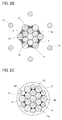
- a strand 1 is subjected to blueing to stabilize a twisted state.
- the side wires 1d in a part of the outer layer of the strand 1 are partly and sequentially detwisted and opened, and a strand composed of the remaining element wires 1a, 1b, and 1c is passed through a kneading tank of a filling resin 4.
- a strand composed of the remaining element wires 1a, 1b, and 1c is passed through a kneading tank of a filling resin 4.
- the strand of 1b and 1c except for the side wires 1d is covered with the filling resin 4.
- the side wires 1d are twisted again.
- the strand 1 to which the filling resin 4 is applied and which is twisted again is passed through a die 5 having an inner peripheral surface shape corresponding to the outer peripheral surface shape of the strand 1, and the filling resin 4 in a part of the outer peripheral surface of the strand 1 (filling resin 4 on the outer peripheral surfaces of the side wires 1c and 1d) is removed. Also, the filling resin 4 is filled between the side wires 1b, 1c, and 1d.
- This means for covering the core wire 1a and the side wires 1b and 1c with resin while partly and sequentially detwisting and opening the inner and outer layers of the strand 1 (detwisting means) is well known, as described in paragraphs 0012 to 0034 and Figs. 1 to 10 of PTL 6.
- a sheath 3 is formed by extrusion with a pregrouted layer 2 being disposed therebetween, similarly to the related art, whereby a pregrouted PC steel material 10 illustrated in Fig. 1 is obtained.
- the filling resin 4 is removed from the outer peripheral surface of the strand 1 by passage through the die 5, and the filling resin 4 between the inner and outer layer steel wires 1b, 1c, and 1d does not exude to the outer periphery of the outer layer, because the steel wires 1b, 1c, and 1d are brought into pressure contact by twisting. For this reason, since the filling resin 4 rarely touches the pregrouted layer 2, the above-described tensionable period can be obtained sufficiently.
- This pregrouted PC steel material 10 is used in the post tensioning method, similarly to the related art. After concrete is cast and hardened, the PC strand 1 is tensioned, and compressive stress is applied to the concrete by the reaction force of the tensioning force.
- the filling resin 4 flew out (exuded) to the pregrouted layer 2.
- the pregrouted layer 2 could be completely cured in a period corresponding to about a half of the period in the related art in which the resin did not flow out.
- the pregrouted PC steel material 10 was wound around a drum, the pregrouted PC steel material 10 was subjected to a bending test (curvature radius: 1.0 m, held for 30 seconds). Exudation of the filling resin 4 was not found.
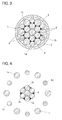
- the filling resin 4 can be filled (in the gaps) between the adjacent side wires 1b and 1b in the inner layer and the side wires 1c.
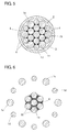
- the filling resin 4 can also be filled (in the gaps) between the core wire 1a and the side wires 1b in the inner layer.
- the side wires 1c and 1d are partly and sequentially detwisted and opened, the side wires 1b are slightly detwisted, and a detwisted strand composed of the steel wires 1a and 1b is passed through the kneading tank of the filling resin 4.
- the strand 1 illustrated in Fig. 2A is used, and is passed through the die 5 illustrated in Fig. 2C .
- Test Examples 1 to 6 of filling resin 4 having compositions shown in the following Table 1 were prepared. After a tensioning load of 726. 3 kN was applied to Test Examples 1 to 6, Test Examples 1 to 6 were stored at 70°C, and the days until the durometer hardness of a type D indenter of a pregrouted layer 2 reached 20 were evaluated. Test Examples 1 to 5 correspond to examples of the present invention, and Test Example 6 corresponds to the related art.
- Test Example 1 Test Example 2 Test Example 3 Test Example 4 Test Example 5 Test Example 6 Filling resin Curing agent component (1) (phr) Ketimine 10 Ketimine 100 Imidazole 100 Polyamine 100 Polyamine 90 None Curing agent component (2) (phr) - - - - Imidazole 10 Filler (1) (phr) Calcium oxide 15 Talc 50 Talc 50 Talc 50 Filler (2) (phr) Silica 5 - - - - Binder component (phr) Epoxy resin 100 - - - - Hours until durometer hardness D reaches 20 (70°C, accelerated) 240 225 129 42 45 276
- the present invention can, of course, also be adopted in a seven-wire-twisted pregrouted PC steel material 10' in which six side wires 1b are twisted together around a core wire 1a, as illustrated in Fig. 7 .
- the side wires 1b in a strand 1' are partly and sequentially detwisted and opened, and the remaining steel wire (core wire 1a) is passed through a kneading tank of a filling resin 4.
- the strand 1' is passed through a die having an inner peripheral surface shape corresponding to an outer peripheral surface shape of the strand 1' to remove the filling resin 4 in a part of the outer peripheral surface of the strand 1'.
- the filling resin 4 is filled (in the gaps) between the side wires 1a and 1b.
- the gap between the layers can be widened by interposing a spacer or the like among the core wire 1a, the inner layer steel wires 1b, and the outer layer steel wires 1c and 1d. While various types of spacers or the like are conceivable, for example, as illustrated in Fig. 8 , when a stringlike spacer 6 is wound on the outer periphery of the inner layer steel wires 1b, it widens the gap surrounded in portions surrounded by the inner layer steel wires 1b and the outer layer steel wires 1c and 1d.
- the filling resin 4 can enter portions within the space in the string of the spacer 6 and surrounded by the side wires 1b and 1c (see Figs. 1 and 8 ).
- a porous sheet or grains, such as capsules can be interposed between the core wire 1a, the inner layer steel wires 1b, and the outer layer steel wires 1c and 1d.
- a tapelike spacer 6 can be wound with a gap.
- the cupules can contain a filling resin.
- the present invention is not limited only to the case in which the conventional curing agent is not compounded in the pregrouted layer 2 at all.
- the pregrouted layer 2 is required to have a certain viscosity at the time of tensioning of the PC strand 1 or 1', it is necessary to obtain a curing action by appropriately compounding a curing agent.
- the required amount of curing agent is, of course, compounded beforehand. That is, as described above, the present invention aims to promote curing of the pregrouted layer 2 by exudation of the filling resin 4 at the time of tensioning of the PC strand 1 or 1'.
Landscapes
- Engineering & Computer Science (AREA)
- Architecture (AREA)
- Civil Engineering (AREA)
- Structural Engineering (AREA)
- Mechanical Engineering (AREA)
- Reinforcement Elements For Buildings (AREA)
- Bridges Or Land Bridges (AREA)
Abstract
Description
- The present invention relates to a pregrouted PC (prestressed concrete) steel material for use in a PC construction method such as a PC post tensioning method, and a curing method for a pregrouted layer in the pregrouted PC steel material.
- A typical post tensioning method tensions and fixes a PC steel material by inserting the PC steel material in a cylindrical sheath buried in concrete beforehand, and applies compressive stress to the concrete by the reaction force of tensioning force. This method covers the disadvantage such that the tensile strength of the concrete is low.
- In this post tensioning method, a grout material, such as cement milk, is injected and mixed between the sheath and the PC steel material to prevent adhesion between the PC steel material and the concrete and corrosion of the PC steel material.
- Since the operation of injecting the grout material is performed at the construction site, it is troublesome and increases the cost. For this reason, a pregrouted PC steel material in which the sheath, the PC steel material, and the grout material described above are provided beforehand has been used. This pregrouted PC steel material includes a PC strand formed by twisting a plurality of steel wires (element wires) together, a pregrouted layer disposed on an outer periphery of the PC strand to contain the PC strand, and a sheath that covers an outer periphery of the pregrouted layer (see paragraph 0005 and
Fig. 2 of PTL 1). - In the post tensioning method using this pregrouted PC steel material, the pregrouted material (pregrouted layer) is required to have a long tensionable period in which the PC grout material does not cure until the PC strand is tensioned, and needs to cure at ordinary temperature after the PC strand is fixed by the application of tensioning force (after concrete is compressed).
- For this reason, to support the action, there have been proposed various kinds of grout materials, that is, a grout material whose composition, viscosity, and so on are determined according to the curing time to cure the grout material in a required time (
PTL 1, claim 1), a grout material in which a curing agent is mixed at a mixture ratio in accordance with the curing time (PTL 2, claim 1), and a grout material whose compounding is devised (PTL 3, claim 1). -
- PTL 1:
Japanese Unexamined Patent Application Publication No. 2003-172001 - PTL 2:
Japanese Unexamined Patent Application Publication No. 2000-281967 - PTL 3:
Japanese Unexamined Patent Application Publication No. 2009-108497 - PTL 4:
Japanese Unexamined Patent Application Publication No. 2007-211486 - PTL 5:
Japanese Unexamined Patent Application Publication No. 2012-154097 - PTL 6:
Japanese Unexamined Patent Application Publication No. 05-200825 - In any of the above-described pregrouted PC steel materials of the related art, the curing agent is mixed beforehand, or compounding or the like of the grout material is devised. However, the curing degree changes according to the environment such as temperature, and the construction period often deviates from the planned period. When the construction period is extended, curing of the grout material proceeds, and this may hinder the operation of tensioning the PC steel material.
- Owing to these circumstances, as a long tensionable period as possible is often required. For this reason, compounding of resin in presently applied pregrouted layer is designed to extend the tensionable period. However, since the tensionable period and the curing time are in a trade-off relationship, several years are generally needed until the pregrouted layer cures completely.
- In contrast, as the means for curing a pregrouted layer at an arbitrary time, heating elements are provided in a sheath (PTL 4). However, it is necessary to energize the heating elements after a PC strand is tensioned, and this makes the operation troublesome.
- Further, capsules containing a curing agent are mixed in a pregrouted layer (
PTL 5, Abstract). However, in this technique, the capsules are broken via the pregrouted layer by tensioning force of a PC steel material so that the curing agent flows into the pregrouted layer. Hence, the capsules may not be broken smoothly. That is, the curing time of the pregrouted layer is unstable. - While paragraph 0022 of
PTL 1 also describes the idea of mixing, in a pregrouted layer, microcapsules in each of which a curing agent is wrapped with a coating film, these capsules are broken by dissolution of the coating film due to water or the like in the pregrouted layer or heat application so that the curing agent therein flows into the pregrouted layer. - In view of the above circumstances, an object of the present invention is to allow a pregrouted layer to be cured by means other than the above-described heating means from an initial period where promotion of curing is demanded.
- To achieve the above object, a pregrouted PC steel material according to the present invention includes a PC strand formed by twisting a plurality of steel wires, a pregrouted layer disposed on an outer periphery of the PC strand to contain the PC strand, and a sheath configured to cover an outer periphery of the pregrouted layer. A filling resin configured to promote curing of the pregrouted layer is filled between the steel wires in the PC strand. The filling resin does not exude to the pregrouted layer before tensioning of the PC strand, and exudes to the pregrouted layer owing to a tensioning force during the tensioning. Advantageous Effects of Invention
- Since the present invention has the above-described features, the filling resin starts flowing out to the pregrouted layer and curing proceeds from an initial period in which promotion of curing of the pregrouted layer is demanded and in which compressive stress is applied to concrete by tensioning the PC strand. Hence, the construction period can be shortened without hindering the operation of tensioning the PC strand.
-
- [
Fig. 1] Figure 1 is a cross-sectional view of a pregrouted PC steel material according to an embodiment of the present invention. - [
Fig. 2A] Figure 2A is an explanatory view illustrating production of the embodiment. - [
Fig. 2B] Figure 2B is an explanatory view illustrating production of the embodiment. - [
Fig. 2C] Figure 2C is an explanatory view illustrating production of the embodiment. - [
Fig. 3] Figure 3 is a cross-sectional view of another embodiment. - [
Fig. 4] Figure 4 is an explanatory view illustrating production of the embodiment. - [
Fig. 5] Figure 5 is a cross-sectional view of a further embodiment. - [
Fig. 6] Figure 6 is an explanatory view illustrating production of the embodiment. - [
Fig. 7] Figure 7 is a cross-sectional view of a still further embodiment. - [
Fig. 8] Figure 8 is a cross-sectional view of an even still further embodiment. Description of Embodiments - A pregrouted PC steel material according to an embodiment of the present invention includes a PC strand formed by twisting a plurality of steel wires, a pregrouted layer disposed on an outer periphery of the PC strand to contain the PC strand, and a sheath that covers an outer periphery of the pregrouted layer. The pregrouted PC steel material adopts a structure in which a filling resin for promoting curing of the pregrouted layer (hereinafter referred to as a filling resin) is filled between the steel wires in the PC strand and the filling resin does not exude to the pregrouted layer before tensioning of the PC strand and exudes to the pregrouted layer owing to tensioning force during the tensioning.
- That is, an initial period in which promotion of curing of the pregrouted layer is demanded is the time when, after concrete is cast, it is subjected to prestressing, that is, a PC steel material is tensioned and fixed and compressive stress is applied to the concrete by reaction force of the tensioning force. For this reason, first, curing of the pregrouted layer is promoted when the compressive stress is applied to the concrete by the tensioning force.
- Next, a filling resin for promoting curing of the pregrouted layer is filled between the steel wires in the PC strand during prestressing in order to promote curing of the pregrouted layer. According to this structure, the filling resin between the steel wires in the PC strand does not exude until the PC strand is tensioned (before tensioning and fixing start), and the filling resin exudes to cure the pregrouted layer only after the gap between the steel wires is reduced during tensioning.
- According to the above, in this structure, the filling resin does not flow out to the pregrouted layer until the PC strand is tensioned, and this does not hinder the operation of tensioning the PC strand by curing of the pregrouted layer. In contrast, when the PC strand is tensioned, the gap between the steel wires is certainly reduced. Hence, the filling resin flows out (exudes) to the pregrouted layer and cures the pregrouted layer only after the reduction. That is, the initial period when curing of the pregrouted layer promoted is the time of prestressing when the PC strand is tensioned to apply compressive stress to the concrete after the concrete is cast.
- In this structure, when a spacer or the like is interposed between layers of the steel wires to widen the gap between the layers to be filled with the filling resin, the amount of filling resin filled in the gap can be increased. Hence, the degree of curing of the pregrouted layer is adjusted easily.
- As the pregrouted layer, well-known resins conventionally used, for example, epoxy resin or a resin mainly composed of epoxy resin can be adopted.
- The filling resin exudes from between the steel wires in the PC strand into the grout resin layer (pregrouted layer) owing to reduction of the gap between the steel wires during the tensioning operation, and thereby promotes curing of the grout resin layer. When the pregrouted layer is formed of epoxy resin or a resin mainly composed of epoxy resin, for example, a curing agent for epoxy resin is conceivable as the filling resin. While the filling resin may be powder or beads obtained by granulating the powder, it may be microcapsules wrapped with coating films that are dissolved by moisture absorption or broken by tensioning force of the PC strand (filled with filling resin).
- While only the curing agent may be used (alone) as the epoxy resin curing agent used in the filling resin, a binder resin can be appropriately mixed therein. While the kind of binder resin is not particularly limited, epoxy resin that can finally cure together with the grout resin is preferably used.
- As the curing agent for epoxy resin, an amine-based compound, an anhydride-based compound, an amide-based compound, a phenol-based compound, and a carboxylic compound are given as examples. These curing agents may be used alone, or two or more of these may be used. While the kind of curing agent is not particularly limited, a ketimine is suitable from the viewpoint of the tensionable period of the steel material.
- As epoxy resin used in the binder resin, a novolac epoxy resin, a bisphenol A epoxy resin, a biphenyl epoxy resin, a triphenylmethane epoxy resin, and a phenolic aralkyl epoxy resin are given as examples. These epoxy resins may be used alone, or two or more of these may be used. While the kind of epoxy resin is not particularly limited, a bisphenol A epoxy resin is suitable because of its viscosity and ease of treatment.
- When the filling resin is a mixture of epoxy resin and an epoxy resin curing agent, the optimal compounding amount of epoxy resin curing agent differs according to the combination thereof. For example, when a bisphenol A epoxy resin and a ketimine are combined, the compounding amount of ketimine is 2.5 to 30 phr, preferably 3.5 to 20 phr, and more preferably 4.5 to 15 phr.
- The curing speed may be insufficient when the compounding amount of ketimine is too small, and the tensionable period of the steel material may be insufficient when the compounding amount of ketimine is too large.
- An organic filler can be added to the filling resin as necessary. This addition of the filler can improve a thickening property, a thixotropic property, and a drip preventive property of the filling resin. As the organic filler, powders of crystalline silica, fused silica, alumina, zircon, calcium silicate, calcium carbonate, calcium oxide, silicon carbide, silicon nitride, boron nitride, zirconia, forsterite, steatite, spinel, titania, and talc or beads formed by spheroidizing these powders are given as examples, but the organic filler is not limited thereto. These fillers may be used alone, or two or more of these may be used. The content of the organic filler is such as to occupy 0 to 95 wt% of the curable resin composite of the present invention. Further, to the filling resin of the present invention, a silane coupling agent, a parting agent, such as stearin acid, palmitic acid, zinc stearate, and calcium stearate, various compounding agents such as pigment, and various thermoplastic resins can be added.
- Similarly to the related art, prestressing of concrete by this pregrouted PC steel material is performed by burying the pregrouted steel material in the concrete beforehand, casting the concrete, and then tensioning a PC strand.
- At this time, the gap between the steel wires in the PC strand is reduced by the tensioning force. The filling resin filled in the gap is caused to exude into the pregrouted layer and cure the pregrouted layer.
-
Figure 1 illustrates an embodiment. Similarly to the related art, a pregroutedPC steel material 10 of this embodiment includes amultilayer PC strand 1 formed by twisting a plurality ofsteel wires pregrouted layer 2 disposed on an outer periphery of thePC strand 1 to contain thePC strand 1 and formed of epoxy resin (grout material), and asheath 3 formed of polyethylene to cover an outer periphery of thepregrouted layer 2. A fillingresin 4 is filled (in gaps) between side wires (steel wires) 1b, 1c, and 1d. - In this embodiment, the diameters of the
steel wires steel wires 1d is about 5 mm, the number of steel wires is 19, the diameter of thePC strand 1 is 28.6 mm, and the sheath thickness is about 1.5 mm. As the fillingresin 4, a mixture of a bisphenol A epoxy resin and a ketimine is used, and the compounding amount of ketimine in the epoxy resin is 10 phr. - To produce the pregrouted
PC steel material 10, first, as illustrated inFig. 2A , six side wires (inner layer steel wires) 1b serving as an inner layer are twisted together around a core wire (steel wire) 1a, and twelve side wires (outer layer steel wires) 1c and 1d serving as an outer layer are twisted together around the inner layer. After stretching or simultaneously with stretching, astrand 1 is subjected to blueing to stabilize a twisted state. - Next, as illustrated in
Fig. 2B , theside wires 1d in a part of the outer layer of thestrand 1 are partly and sequentially detwisted and opened, and a strand composed of the remainingelement wires resin 4. By this passage through the kneading tank, the strand of 1b and 1c except for theside wires 1d is covered with the fillingresin 4. After that, theside wires 1d are twisted again. As illustrated inFig. 2C , thestrand 1 to which the fillingresin 4 is applied and which is twisted again is passed through adie 5 having an inner peripheral surface shape corresponding to the outer peripheral surface shape of thestrand 1, and the fillingresin 4 in a part of the outer peripheral surface of the strand 1 (fillingresin 4 on the outer peripheral surfaces of theside wires resin 4 is filled between theside wires core wire 1a and theside wires Figs. 1 to 10 ofPTL 6. - On the outer periphery of the strand (PC strand) 1 in which the filling
resin 4 is thus filled between theside wires sheath 3 is formed by extrusion with apregrouted layer 2 being disposed therebetween, similarly to the related art, whereby a pregroutedPC steel material 10 illustrated inFig. 1 is obtained. When thePC strand 1 is contained in thepregrouted layer 2, the fillingresin 4 is removed from the outer peripheral surface of thestrand 1 by passage through thedie 5, and the fillingresin 4 between the inner and outerlayer steel wires steel wires resin 4 rarely touches thepregrouted layer 2, the above-described tensionable period can be obtained sufficiently. - This pregrouted
PC steel material 10 is used in the post tensioning method, similarly to the related art. After concrete is cast and hardened, thePC strand 1 is tensioned, and compressive stress is applied to the concrete by the reaction force of the tensioning force. - At this time, when the tensioning force of the
PC strand 1 was 500 to 700 kN, the fillingresin 4 flew out (exuded) to thepregrouted layer 2. By the flow of the fillingresin 4, thepregrouted layer 2 could be completely cured in a period corresponding to about a half of the period in the related art in which the resin did not flow out. - Assuming that the pregrouted
PC steel material 10 was wound around a drum, the pregroutedPC steel material 10 was subjected to a bending test (curvature radius: 1.0 m, held for 30 seconds). Exudation of the fillingresin 4 was not found. - In this embodiment, as illustrated in
Fig. 3 , the fillingresin 4 can be filled (in the gaps) between theadjacent side wires side wires 1c. At this time, as illustrated inFig. 4 , while theside wires steel wires resin 4. Further, as illustrated inFig. 5 , the fillingresin 4 can also be filled (in the gaps) between thecore wire 1a and theside wires 1b in the inner layer. At this time, as illustrated inFig. 6 , theside wires side wires 1b are slightly detwisted, and a detwisted strand composed of thesteel wires resin 4. In any of the cases, thestrand 1 illustrated inFig. 2A is used, and is passed through thedie 5 illustrated inFig. 2C . - To confirm that the pregrouted
PC steel material 10 according to the present invention is excellent, in the pregroutedPC steel material 10 having the structure of the above embodiment illustrated inFig. 1 , Test Examples 1 to 6 of fillingresin 4 having compositions shown in the following Table 1 were prepared. After a tensioning load of 726. 3 kN was applied to Test Examples 1 to 6, Test Examples 1 to 6 were stored at 70°C, and the days until the durometer hardness of a type D indenter of apregrouted layer 2 reached 20 were evaluated. Test Examples 1 to 5 correspond to examples of the present invention, and Test Example 6 corresponds to the related art.[Table] Test Example 1 Test Example 2 Test Example 3 Test Example 4 Test Example 5 Test Example 6 Filling resin Curing agent component (1) (phr) Ketimine 10Ketimine 100 Imidazole 100 Polyamine 100 Polyamine 90 None Curing agent component (2) (phr) - - - - Imidazole 10Filler (1) (phr) Calcium oxide 15 Talc 50 Talc 50 Talc 50 Talc 50 Filler (2) (phr) Silica 5 - - - - Binder component (phr) Epoxy resin 100 - - - - Hours until durometer hardness D reaches 20 (70°C, accelerated) 240 225 129 42 45 276 - From the comparison between Test Examples 1 to 5 and Test Example 6, it can be confirmed that the number of days until the
pregrouted layer 2 cures after tensioning is decreased by filling the fillingresin 4. Further, from the comparison of Test Examples 1 to 5, it can be confirmed that the number of days until thepregrouted layer 2 cures after tensioning decreases as the content of the curing agent component in the fillingresin 4 increases. Still further, it can be confirmed that polyamine is excellent as the curing agent. - The present invention can, of course, also be adopted in a seven-wire-twisted pregrouted PC steel material 10' in which six
side wires 1b are twisted together around acore wire 1a, as illustrated inFig. 7 . Similarly to the above, in this pregrouted PC steel material 10', theside wires 1b in a strand 1' are partly and sequentially detwisted and opened, and the remaining steel wire (core wire 1a) is passed through a kneading tank of a fillingresin 4. After that, the strand 1' is passed through a die having an inner peripheral surface shape corresponding to an outer peripheral surface shape of the strand 1' to remove the fillingresin 4 in a part of the outer peripheral surface of the strand 1'. Also, the fillingresin 4 is filled (in the gaps) between theside wires - To increase the amount of filling
resin 4 to be exuded by the tensioning load, the gap between the layers can be widened by interposing a spacer or the like among thecore wire 1a, the innerlayer steel wires 1b, and the outerlayer steel wires Fig. 8 , when astringlike spacer 6 is wound on the outer periphery of the innerlayer steel wires 1b, it widens the gap surrounded in portions surrounded by the innerlayer steel wires 1b and the outerlayer steel wires resin 4 can enter portions within the space in the string of thespacer 6 and surrounded by theside wires Figs. 1 and8 ). Instead of thestringlike spacer 6, for example, a porous sheet or grains, such as capsules, can be interposed between thecore wire 1a, the innerlayer steel wires 1b, and the outerlayer steel wires tapelike spacer 6 can be wound with a gap. The cupules can contain a filling resin. - Incidentally, the present invention is not limited only to the case in which the conventional curing agent is not compounded in the
pregrouted layer 2 at all. For example, when thepregrouted layer 2 is required to have a certain viscosity at the time of tensioning of thePC strand 1 or 1', it is necessary to obtain a curing action by appropriately compounding a curing agent. In such a case, the required amount of curing agent is, of course, compounded beforehand. That is, as described above, the present invention aims to promote curing of thepregrouted layer 2 by exudation of the fillingresin 4 at the time of tensioning of thePC strand 1 or 1'. - Well-known grout materials other than epoxy resin can be appropriately adopted, and, of course, a filling
resin 4 is adopted according to the grout materials. - In this way, it should be considered that the embodiments disclosed herein are merely examples in all respects, but are not restrictive. The scope of the present invention is defined by the claims, and it is intended to include all modifications within the scope of the claims and the equivalents thereof.
-
- 1, 1'
- PC strand
- 1a
- core wire (steel wire)
- 1b
- inner layer side wire (steel wire)
- 1c
- outer layer side wire (steel wire)
- 1d
- outer layer side wire (steel wire)
- 2
- pregrouted layer
- 3
- sheath
- 4
- filling resin
- 5
- die
- 6
- spacer
- 10, 10'
- PC steel material
Claims (6)
- A pregrouted PC steel material comprising: a PC strand formed by twisting a plurality of steel wires; a pregrouted layer disposed on an outer periphery of the PC strand to contain the PC strand; and a sheath configured to cover an outer periphery of the pregrouted layer,
wherein a filling resin configured to promote curing of the pregrouted layer is filled between the steel wires in the PC strand, and the filling resin does not exude to the pregrouted layer before tensioning of the PC strand, and exudes to the pregrouted layer owing to a tensioning force during the tensioning. - The pregrouted PC steel material according to Claim 1, wherein a gap filled with the filling resin between layers of the steel wires is widened by interposing a spacer between the layers.
- The pregrouted PC steel material according to Claim 1 or 2, wherein the pregrouted layer is formed of epoxy resin or a resin mainly composed of epoxy resin, and the filling resin is a curing agent for the epoxy resin.
- The pregrouted PC steel material according to Claim 1 or 2, wherein the pregrouted layer is formed of epoxy resin or a resin mainly composed of epoxy resin, and the filling resin is a mixture of epoxy resin and a curing agent for the epoxy resin.
- The pregrouted PC steel material according to any one of Claims 1 to 4, wherein a filler is added to the filling resin to achieve thickening, to improve a thixotropic property, or to prevent dripping.
- A curing method for the pregrouted layer in the pregrouted PC steel material according to any one of Claims 1 to 5, wherein the pregrouted PC steel material is buried in concrete, and the filling resin is caused to flow into the pregrouted layer to cure the pregrouted layer by the tensioning force when the PC strand is tensioned to apply compressive force to the concrete.
Applications Claiming Priority (3)
| Application Number | Priority Date | Filing Date | Title |
|---|---|---|---|
| JP2013266343 | 2013-12-25 | ||
| JP2014245912A JP6480719B2 (en) | 2013-12-25 | 2014-12-04 | PREGROUT PC STEEL AND METHOD OF CURING THE PREGROUT LAYER |
| PCT/JP2014/083527 WO2015098683A1 (en) | 2013-12-25 | 2014-12-18 | Pregrouted pc steel and method for hardening pregrouted layer |
Publications (3)
| Publication Number | Publication Date |
|---|---|
| EP3088634A1 true EP3088634A1 (en) | 2016-11-02 |
| EP3088634A4 EP3088634A4 (en) | 2016-12-21 |
| EP3088634B1 EP3088634B1 (en) | 2020-09-23 |
Family
ID=53478544
Family Applications (1)
| Application Number | Title | Priority Date | Filing Date |
|---|---|---|---|
| EP14875354.4A Active EP3088634B1 (en) | 2013-12-25 | 2014-12-18 | Pregrouted pc steel and method for hardening pregrouted layer |
Country Status (11)
| Country | Link |
|---|---|
| US (1) | US10323415B2 (en) |
| EP (1) | EP3088634B1 (en) |
| JP (1) | JP6480719B2 (en) |
| KR (1) | KR102238476B1 (en) |
| CN (1) | CN105247149B (en) |
| BR (1) | BR112015032880A2 (en) |
| CA (1) | CA2911644C (en) |
| ES (1) | ES2829702T3 (en) |
| RU (1) | RU2659915C2 (en) |
| WO (1) | WO2015098683A1 (en) |
| ZA (1) | ZA201507751B (en) |
Families Citing this family (3)
| Publication number | Priority date | Publication date | Assignee | Title |
|---|---|---|---|---|
| TW202038754A (en) * | 2019-03-11 | 2020-11-01 | 英商尼可創業貿易有限公司 | Aerosol provision device |
| CN113288381B (en) * | 2021-05-31 | 2022-08-26 | 河北省胸科医院 | Combined external fixing frame for fracture and using method thereof |
| CN116633059B (en) * | 2023-05-15 | 2024-05-14 | 浙江大学 | A motor forming winding structure and processing method thereof |
Family Cites Families (20)
| Publication number | Priority date | Publication date | Assignee | Title |
|---|---|---|---|---|
| US3747361A (en) * | 1971-10-05 | 1973-07-24 | Westinghouse Electric Corp | Control arrangement for refrigerator-freezer having fast chill feature |
| GB8314417D0 (en) * | 1983-05-25 | 1983-06-29 | Psc Freyssinet Ltd | Tendons for concrete structures |
| AU587442B2 (en) | 1985-04-08 | 1989-08-17 | Sumitomo Electric Industries, Ltd. | Prestressing steel material |
| JPH0538818B2 (en) * | 1985-04-08 | 1993-06-11 | Sumitomo Electric Industries | Pc steel material |
| US5208077A (en) | 1990-11-09 | 1993-05-04 | Florida Wire And Cable Company | Method for a composite material comprising coated and filled metal strand for use in prestressed concrete, stay cables for cable-stayed bridges and other uses |
| JP2552604B2 (en) | 1992-01-30 | 1996-11-13 | 黒沢建設株式会社 | Method for forming synthetic resin coating on PC steel strand and PC strand formed with synthetic resin coating |
| JP2676594B2 (en) | 1995-02-21 | 1997-11-17 | 株式会社英布 | Method for producing anticorrosion coated steel strand |
| JPH10226973A (en) * | 1997-02-13 | 1998-08-25 | Hien Denko Kk | Anti-corrosion coated low relaxation PC strand and its manufacturing method |
| JP4397995B2 (en) | 1999-03-31 | 2010-01-13 | 住友電工スチールワイヤー株式会社 | Curable composition and tendon for sheath-coated prestressed concrete tendon |
| JP3786599B2 (en) * | 2001-12-05 | 2006-06-14 | 住友電工スチールワイヤー株式会社 | PRC structure bridge |
| JP2005171581A (en) | 2003-12-10 | 2005-06-30 | East Japan Railway Co | Method for manufacturing prestressed concrete member |
| JP4388524B2 (en) | 2006-02-09 | 2009-12-24 | 住友電工スチールワイヤー株式会社 | Pre-grout PC steel and method for producing the same |
| JP2008255183A (en) * | 2007-04-03 | 2008-10-23 | Sumitomo Electric Ind Ltd | Curable resin composition for pre-grout steel and prestressed concrete tendon |
| JP5038818B2 (en) * | 2007-08-22 | 2012-10-03 | 株式会社オートネットワーク技術研究所 | Board connector |
| JP4944732B2 (en) * | 2007-10-26 | 2012-06-06 | 住友電気工業株式会社 | Pre-grout PC steel and PC construction method |
| CN201128973Y (en) * | 2007-11-13 | 2008-10-08 | 天津市鑫坤泰银桥预应力商贸有限公司 | Retard-bonded prestressed wire |
| RU2009113489A (en) * | 2009-04-13 | 2010-10-20 | Сергей Львович Ситников (RU) | METHOD FOR PRODUCING PRELIMINARY STRESSED REINFORCED CONCRETE STRUCTURES WITH REINFORCED BEAMS |
| JP2012117243A (en) | 2010-11-30 | 2012-06-21 | Sumitomo Electric Ind Ltd | Pregrouted pc steel material and method of hardening pregrout layer of the same |
| JP5727242B2 (en) * | 2011-01-26 | 2015-06-03 | 住友電気工業株式会社 | PREGROUT PC STEEL AND METHOD OF CURING THE PREGROUT LAYER |
| US10081943B2 (en) | 2012-07-31 | 2018-09-25 | Sumitomo (Sei) Steel Wire Corp. | Pregrouted PC steel material and method for hardening pregrout layer thereof |
-
2014
- 2014-12-04 JP JP2014245912A patent/JP6480719B2/en active Active
- 2014-12-18 KR KR1020157033207A patent/KR102238476B1/en active Active
- 2014-12-18 BR BR112015032880A patent/BR112015032880A2/en active Search and Examination
- 2014-12-18 EP EP14875354.4A patent/EP3088634B1/en active Active
- 2014-12-18 CN CN201480030208.6A patent/CN105247149B/en active Active
- 2014-12-18 RU RU2015150345A patent/RU2659915C2/en active
- 2014-12-18 CA CA2911644A patent/CA2911644C/en active Active
- 2014-12-18 WO PCT/JP2014/083527 patent/WO2015098683A1/en not_active Ceased
- 2014-12-18 US US14/891,638 patent/US10323415B2/en active Active
- 2014-12-18 ES ES14875354T patent/ES2829702T3/en active Active
-
2015
- 2015-10-16 ZA ZA2015/07751A patent/ZA201507751B/en unknown
Also Published As
| Publication number | Publication date |
|---|---|
| RU2015150345A (en) | 2018-01-30 |
| KR102238476B1 (en) | 2021-04-08 |
| KR20160101853A (en) | 2016-08-26 |
| JP2015143464A (en) | 2015-08-06 |
| ZA201507751B (en) | 2017-04-26 |
| RU2659915C2 (en) | 2018-07-04 |
| RU2015150345A3 (en) | 2018-04-25 |
| WO2015098683A1 (en) | 2015-07-02 |
| ES2829702T3 (en) | 2021-06-01 |
| US20160076250A1 (en) | 2016-03-17 |
| EP3088634A4 (en) | 2016-12-21 |
| BR112015032880A2 (en) | 2020-02-11 |
| JP6480719B2 (en) | 2019-03-13 |
| EP3088634B1 (en) | 2020-09-23 |
| US10323415B2 (en) | 2019-06-18 |
| CN105247149B (en) | 2018-07-31 |
| CN105247149A (en) | 2016-01-13 |
| CA2911644C (en) | 2021-12-07 |
| CA2911644A1 (en) | 2015-07-02 |
Similar Documents
| Publication | Publication Date | Title |
|---|---|---|
| US6655104B2 (en) | PC steel stranded wire connection structure and construction method thereof | |
| KR102100349B1 (en) | Pregrouted pc steel material and method for hardening pregrout layer thereof | |
| KR101150352B1 (en) | Saddle system and cable for tension | |
| EP3088634B1 (en) | Pregrouted pc steel and method for hardening pregrouted layer | |
| JP7226455B2 (en) | Insulated wires and wire harnesses | |
| JP5727242B2 (en) | PREGROUT PC STEEL AND METHOD OF CURING THE PREGROUT LAYER | |
| CN212836267U (en) | Stretch-draw bonding pre-grouting prestressed tendon | |
| JP2012117243A (en) | Pregrouted pc steel material and method of hardening pregrout layer of the same | |
| JPWO2009020176A1 (en) | Pre-grout PC steel and PC post tension method | |
| JP4944732B2 (en) | Pre-grout PC steel and PC construction method | |
| JP4634317B2 (en) | Method for producing resin-coated PC steel stranded wire, and apparatus for producing resin-coated PC steel stranded wire | |
| EP0219894A1 (en) | Tendons with deferred bonding and method for stressing concrete, as well as prestressed concrete elements | |
| JP2007211486A (en) | Pre-grout PC steel and method for producing the same | |
| JPH062333B2 (en) | Method for manufacturing multi-type fixing device for prestressed concrete | |
| JP2023155566A (en) | Tensile anchorage structure and method for manufacturing prestressed concrete structures |
Legal Events
| Date | Code | Title | Description |
|---|---|---|---|
| PUAI | Public reference made under article 153(3) epc to a published international application that has entered the european phase |
Free format text: ORIGINAL CODE: 0009012 |
|
| 17P | Request for examination filed |
Effective date: 20151124 |
|
| AK | Designated contracting states |
Kind code of ref document: A1 Designated state(s): AL AT BE BG CH CY CZ DE DK EE ES FI FR GB GR HR HU IE IS IT LI LT LU LV MC MK MT NL NO PL PT RO RS SE SI SK SM TR |
|
| AX | Request for extension of the european patent |
Extension state: BA ME |
|
| A4 | Supplementary search report drawn up and despatched |
Effective date: 20161121 |
|
| RIC1 | Information provided on ipc code assigned before grant |
Ipc: E04C 5/08 20060101ALI20161115BHEP Ipc: E04G 21/12 20060101AFI20161115BHEP Ipc: B28B 23/04 20060101ALI20161115BHEP Ipc: E04C 5/10 20060101ALN20161115BHEP |
|
| DAX | Request for extension of the european patent (deleted) | ||
| RAP1 | Party data changed (applicant data changed or rights of an application transferred) |
Owner name: SUMITOMO ELECTRIC INDUSTRIES, LTD. |
|
| STAA | Information on the status of an ep patent application or granted ep patent |
Free format text: STATUS: EXAMINATION IS IN PROGRESS |
|
| 17Q | First examination report despatched |
Effective date: 20200123 |
|
| GRAP | Despatch of communication of intention to grant a patent |
Free format text: ORIGINAL CODE: EPIDOSNIGR1 |
|
| STAA | Information on the status of an ep patent application or granted ep patent |
Free format text: STATUS: GRANT OF PATENT IS INTENDED |
|
| INTG | Intention to grant announced |
Effective date: 20200423 |
|
| GRAS | Grant fee paid |
Free format text: ORIGINAL CODE: EPIDOSNIGR3 |
|
| GRAA | (expected) grant |
Free format text: ORIGINAL CODE: 0009210 |
|
| STAA | Information on the status of an ep patent application or granted ep patent |
Free format text: STATUS: THE PATENT HAS BEEN GRANTED |
|
| AK | Designated contracting states |
Kind code of ref document: B1 Designated state(s): AL AT BE BG CH CY CZ DE DK EE ES FI FR GB GR HR HU IE IS IT LI LT LU LV MC MK MT NL NO PL PT RO RS SE SI SK SM TR |
|
| REG | Reference to a national code |
Ref country code: GB Ref legal event code: FG4D |
|
| REG | Reference to a national code |
Ref country code: CH Ref legal event code: EP |
|
| REG | Reference to a national code |
Ref country code: DE Ref legal event code: R096 Ref document number: 602014070601 Country of ref document: DE |
|
| REG | Reference to a national code |
Ref country code: IE Ref legal event code: FG4D |
|
| REG | Reference to a national code |
Ref country code: AT Ref legal event code: REF Ref document number: 1316519 Country of ref document: AT Kind code of ref document: T Effective date: 20201015 |
|
| REG | Reference to a national code |
Ref country code: CH Ref legal event code: NV Representative=s name: KIRKER AND CIE S.A., CH |
|
| REG | Reference to a national code |
Ref country code: NL Ref legal event code: FP |
|
| PG25 | Lapsed in a contracting state [announced via postgrant information from national office to epo] |
Ref country code: FI Free format text: LAPSE BECAUSE OF FAILURE TO SUBMIT A TRANSLATION OF THE DESCRIPTION OR TO PAY THE FEE WITHIN THE PRESCRIBED TIME-LIMIT Effective date: 20200923 Ref country code: NO Free format text: LAPSE BECAUSE OF FAILURE TO SUBMIT A TRANSLATION OF THE DESCRIPTION OR TO PAY THE FEE WITHIN THE PRESCRIBED TIME-LIMIT Effective date: 20201223 Ref country code: GR Free format text: LAPSE BECAUSE OF FAILURE TO SUBMIT A TRANSLATION OF THE DESCRIPTION OR TO PAY THE FEE WITHIN THE PRESCRIBED TIME-LIMIT Effective date: 20201224 Ref country code: HR Free format text: LAPSE BECAUSE OF FAILURE TO SUBMIT A TRANSLATION OF THE DESCRIPTION OR TO PAY THE FEE WITHIN THE PRESCRIBED TIME-LIMIT Effective date: 20200923 Ref country code: BG Free format text: LAPSE BECAUSE OF FAILURE TO SUBMIT A TRANSLATION OF THE DESCRIPTION OR TO PAY THE FEE WITHIN THE PRESCRIBED TIME-LIMIT Effective date: 20201223 Ref country code: SE Free format text: LAPSE BECAUSE OF FAILURE TO SUBMIT A TRANSLATION OF THE DESCRIPTION OR TO PAY THE FEE WITHIN THE PRESCRIBED TIME-LIMIT Effective date: 20200923 |
|
| PG25 | Lapsed in a contracting state [announced via postgrant information from national office to epo] |
Ref country code: LV Free format text: LAPSE BECAUSE OF FAILURE TO SUBMIT A TRANSLATION OF THE DESCRIPTION OR TO PAY THE FEE WITHIN THE PRESCRIBED TIME-LIMIT Effective date: 20200923 Ref country code: RS Free format text: LAPSE BECAUSE OF FAILURE TO SUBMIT A TRANSLATION OF THE DESCRIPTION OR TO PAY THE FEE WITHIN THE PRESCRIBED TIME-LIMIT Effective date: 20200923 |
|
| REG | Reference to a national code |
Ref country code: LT Ref legal event code: MG4D |
|
| PG25 | Lapsed in a contracting state [announced via postgrant information from national office to epo] |
Ref country code: CZ Free format text: LAPSE BECAUSE OF FAILURE TO SUBMIT A TRANSLATION OF THE DESCRIPTION OR TO PAY THE FEE WITHIN THE PRESCRIBED TIME-LIMIT Effective date: 20200923 Ref country code: EE Free format text: LAPSE BECAUSE OF FAILURE TO SUBMIT A TRANSLATION OF THE DESCRIPTION OR TO PAY THE FEE WITHIN THE PRESCRIBED TIME-LIMIT Effective date: 20200923 Ref country code: RO Free format text: LAPSE BECAUSE OF FAILURE TO SUBMIT A TRANSLATION OF THE DESCRIPTION OR TO PAY THE FEE WITHIN THE PRESCRIBED TIME-LIMIT Effective date: 20200923 Ref country code: SM Free format text: LAPSE BECAUSE OF FAILURE TO SUBMIT A TRANSLATION OF THE DESCRIPTION OR TO PAY THE FEE WITHIN THE PRESCRIBED TIME-LIMIT Effective date: 20200923 Ref country code: LT Free format text: LAPSE BECAUSE OF FAILURE TO SUBMIT A TRANSLATION OF THE DESCRIPTION OR TO PAY THE FEE WITHIN THE PRESCRIBED TIME-LIMIT Effective date: 20200923 Ref country code: PT Free format text: LAPSE BECAUSE OF FAILURE TO SUBMIT A TRANSLATION OF THE DESCRIPTION OR TO PAY THE FEE WITHIN THE PRESCRIBED TIME-LIMIT Effective date: 20210125 |
|
| PG25 | Lapsed in a contracting state [announced via postgrant information from national office to epo] |
Ref country code: IS Free format text: LAPSE BECAUSE OF FAILURE TO SUBMIT A TRANSLATION OF THE DESCRIPTION OR TO PAY THE FEE WITHIN THE PRESCRIBED TIME-LIMIT Effective date: 20210123 Ref country code: PL Free format text: LAPSE BECAUSE OF FAILURE TO SUBMIT A TRANSLATION OF THE DESCRIPTION OR TO PAY THE FEE WITHIN THE PRESCRIBED TIME-LIMIT Effective date: 20200923 Ref country code: AL Free format text: LAPSE BECAUSE OF FAILURE TO SUBMIT A TRANSLATION OF THE DESCRIPTION OR TO PAY THE FEE WITHIN THE PRESCRIBED TIME-LIMIT Effective date: 20200923 |
|
| REG | Reference to a national code |
Ref country code: ES Ref legal event code: FG2A Ref document number: 2829702 Country of ref document: ES Kind code of ref document: T3 Effective date: 20210601 |
|
| REG | Reference to a national code |
Ref country code: AT Ref legal event code: UEP Ref document number: 1316519 Country of ref document: AT Kind code of ref document: T Effective date: 20200923 |
|
| REG | Reference to a national code |
Ref country code: DE Ref legal event code: R097 Ref document number: 602014070601 Country of ref document: DE |
|
| PG25 | Lapsed in a contracting state [announced via postgrant information from national office to epo] |
Ref country code: SK Free format text: LAPSE BECAUSE OF FAILURE TO SUBMIT A TRANSLATION OF THE DESCRIPTION OR TO PAY THE FEE WITHIN THE PRESCRIBED TIME-LIMIT Effective date: 20200923 |
|
| PLBE | No opposition filed within time limit |
Free format text: ORIGINAL CODE: 0009261 |
|
| STAA | Information on the status of an ep patent application or granted ep patent |
Free format text: STATUS: NO OPPOSITION FILED WITHIN TIME LIMIT |
|
| PG25 | Lapsed in a contracting state [announced via postgrant information from national office to epo] |
Ref country code: SI Free format text: LAPSE BECAUSE OF FAILURE TO SUBMIT A TRANSLATION OF THE DESCRIPTION OR TO PAY THE FEE WITHIN THE PRESCRIBED TIME-LIMIT Effective date: 20200923 Ref country code: DK Free format text: LAPSE BECAUSE OF FAILURE TO SUBMIT A TRANSLATION OF THE DESCRIPTION OR TO PAY THE FEE WITHIN THE PRESCRIBED TIME-LIMIT Effective date: 20200923 Ref country code: MC Free format text: LAPSE BECAUSE OF FAILURE TO SUBMIT A TRANSLATION OF THE DESCRIPTION OR TO PAY THE FEE WITHIN THE PRESCRIBED TIME-LIMIT Effective date: 20200923 |
|
| 26N | No opposition filed |
Effective date: 20210624 |
|
| PG25 | Lapsed in a contracting state [announced via postgrant information from national office to epo] |
Ref country code: IE Free format text: LAPSE BECAUSE OF NON-PAYMENT OF DUE FEES Effective date: 20201218 Ref country code: LU Free format text: LAPSE BECAUSE OF NON-PAYMENT OF DUE FEES Effective date: 20201218 |
|
| PG25 | Lapsed in a contracting state [announced via postgrant information from national office to epo] |
Ref country code: TR Free format text: LAPSE BECAUSE OF FAILURE TO SUBMIT A TRANSLATION OF THE DESCRIPTION OR TO PAY THE FEE WITHIN THE PRESCRIBED TIME-LIMIT Effective date: 20200923 Ref country code: MT Free format text: LAPSE BECAUSE OF FAILURE TO SUBMIT A TRANSLATION OF THE DESCRIPTION OR TO PAY THE FEE WITHIN THE PRESCRIBED TIME-LIMIT Effective date: 20200923 Ref country code: CY Free format text: LAPSE BECAUSE OF FAILURE TO SUBMIT A TRANSLATION OF THE DESCRIPTION OR TO PAY THE FEE WITHIN THE PRESCRIBED TIME-LIMIT Effective date: 20200923 |
|
| PG25 | Lapsed in a contracting state [announced via postgrant information from national office to epo] |
Ref country code: MK Free format text: LAPSE BECAUSE OF FAILURE TO SUBMIT A TRANSLATION OF THE DESCRIPTION OR TO PAY THE FEE WITHIN THE PRESCRIBED TIME-LIMIT Effective date: 20200923 |
|
| P01 | Opt-out of the competence of the unified patent court (upc) registered |
Effective date: 20230515 |
|
| PGFP | Annual fee paid to national office [announced via postgrant information from national office to epo] |
Ref country code: NL Payment date: 20251112 Year of fee payment: 12 |
|
| REG | Reference to a national code |
Ref country code: CH Ref legal event code: U11 Free format text: ST27 STATUS EVENT CODE: U-0-0-U10-U11 (AS PROVIDED BY THE NATIONAL OFFICE) Effective date: 20260101 |
|
| PGFP | Annual fee paid to national office [announced via postgrant information from national office to epo] |
Ref country code: DE Payment date: 20251028 Year of fee payment: 12 |
|
| PGFP | Annual fee paid to national office [announced via postgrant information from national office to epo] |
Ref country code: GB Payment date: 20251030 Year of fee payment: 12 |
|
| PGFP | Annual fee paid to national office [announced via postgrant information from national office to epo] |
Ref country code: AT Payment date: 20251126 Year of fee payment: 12 |
|
| PGFP | Annual fee paid to national office [announced via postgrant information from national office to epo] |
Ref country code: IT Payment date: 20251121 Year of fee payment: 12 |
|
| PGFP | Annual fee paid to national office [announced via postgrant information from national office to epo] |
Ref country code: FR Payment date: 20251110 Year of fee payment: 12 |
|
| PGFP | Annual fee paid to national office [announced via postgrant information from national office to epo] |
Ref country code: BE Payment date: 20251117 Year of fee payment: 12 |
|
| PGFP | Annual fee paid to national office [announced via postgrant information from national office to epo] |
Ref country code: ES Payment date: 20260108 Year of fee payment: 12 |
|
| PGFP | Annual fee paid to national office [announced via postgrant information from national office to epo] |
Ref country code: CH Payment date: 20260101 Year of fee payment: 12 |